


InFocus IN116XV, IN116xa, IN114XV, IN114xa, IN112XV User Manual
...Table of Contents
Table of Contents............................. |
1 |
Usage Notice.................................... |
2 |
Safety Information............................... |
2 |
Precautions......................................... |
3 |
Product Features................................. |
5 |
Introduction...................................... |
6 |
Package Overview.............................. |
6 |
Product Overview................................ |
7 |
Main Unit.............................................. |
7 |
Control Panel........................................ |
8 |
Input/Output Connections..................... |
9 |
Remote Control.................................. |
11 |
Installation...................................... |
12 |
Connecting the Projector................... |
12 |
Connect to Computer/Notebook......... |
12 |
Connect to Video Sources.................. |
14 |
Powering the Projector On / Off........ |
16 |
Powering On the Projector................. |
16 |
Powering off the projector.................. |
17 |
Warning Indicator............................... |
17 |
Adjusting the Projected Image.......... |
18 |
Adjusting the Projector’s Height ........ |
18 |
Adjusting the Projector’s Zoom / |
|
Focus.................................................. |
19 |
Adjusting Projection Image Size......... |
19 |
User Controls................................. |
21 |
Control Panel & Remote Control....... |
21 |
Control Panel...................................... |
21 |
Remote Control Battery Installation.... |
22 |
Remote Control.................................. |
23 |
On-screen Display Menus................. |
27 |
How to operate................................... |
27 |
Menu Tree.......................................... |
28 |
IMAGE................................................ |
30 |
IMAGE | Advanced............................. |
32 |
IMAGE | Advanced | Signal (RGB) .... |
34 |
DISPLAY............................................. |
35 |
DISPLAY | 3D .................................... |
38 |
SETUP................................................ |
39 |
SETUP | Audio Settings...................... |
41 |
SETUP | Advanced............................. |
42 |
OPTIONS........................................... |
43 |
OPTIONS | Advanced........................ |
45 |
OPTIONS | Lamp Settings................. |
46 |
OPTIONS | Optional Filter Settings.... |
47 |
Appendices.................................... |
48 |
Troubleshooting................................. |
48 |
Replacing the Lamp.......................... |
54 |
Installing and Cleaning the Dust |
|
Filter.................................................. |
56 |
Compatibility Modes.......................... |
57 |
Computer/Video/HDMI/Mac |
|
Compatibility....................................... |
57 |
3D Input Video Compatibility.............. |
58 |
RS232 Commands and Protocol |
|
Function List...................................... |
59 |
RS232 Pin Assignments..................... |
59 |
RS232 Protocol Function List............. |
60 |
Ceiling Mount Installation.................. |
64 |
Regulation & Safety Notices.............. |
65 |
1 English
Usage Notice
Safety Information
The lightning flash with arrow head within an equilateral triangle is intended to alert the user to the presence of uninsulated “dangerous voltage” within the product’s enclosure that may be of sufficient magnitude to constitute a risk of electric shock to persons.
The exclamation point within an equilateral triangle is intended to alert the user to the presence of important operating and maintenance (servicing) instructions in the literature accompanying the appliance.
WARNING: TO REDUCE THE RISK OF FIRE OR ELECTRIC SHOCK, DO NOT EXPOSE THIS APPLIANCE TO RAIN OR MOISTURE. DANGEROUS HIGH VOLTAGES ARE PRESENT INSIDE THE ENCLOSURE. DO NOT OPEN THE CABINET. REFER SERVICING TO QUALIFIED PERSONNEL ONLY.
Class B emissions limits
This Class B digital apparatus meets all requirements of the Canadian Interference-Causing Equipment Regulations.
Important Safety Instruction
1.Do not block any ventilation openings. To ensure reliable operation of the projector and to protect from over heating, it is recommended to install the projector in a location that does not block ventilation. As an example, do not place the projector on a crowded coffee table, sofa, bed, etc. Do not put the projector in an enclosure such as a book case or a cabinet that restricts air flow.
2.Do not use the projector near water or moisture. To reduce the risk of fire and/or electric shock, do not expose the projector to rain or moisture.
3.Do not install near heat sources such as radiators, heaters, stoves or any other apparatus such as amplifiers that emits heat.
4.Clean only with dry cloth.
5.Only use attachments/accessories specified by the manufacturer.
6.Do not use the unit if it has been physically damaged or abused.
Physical damage/abuse would be (but not limited to):
Unit has been dropped.
Power supply cord or plug has been damaged.
Liquid has been spilled on to the projector.
Projector has been exposed to rain or moisture.
Something has fallen in the projector or something is loose inside.
Do not attempt to service the unit yourself. Opening or removing covers may expose you to dangerous voltages or other hazards. Please call
InFocus before you send the unit for repair.
7.Do not let objects or liquids enter the projector. They may touch dangerous voltage points and short out parts that could result in fire or electric shock.
8.See projector enclosure for safety related markings.
9.The unit should only be repaired by appropriate service personnel.
English 2

Usage Notice
When the lamp reaches the end of its life, the projector will not turn back on until the lamp module has been replaced.
To replace the lamp, follow the procedures listed under “Replacing the Lamp” section on pages 54-55.
Precautions
Please follow all warnings, precautions and maintenance as recommended in this user’s guide.
▀■ WarningDo not look into the projector’s lens when the lamp is on. The bright light may hurt and damage your eyes.
▀■ WarningTo reduce the risk of fire or electric shock, do not expose this projector to rain or moisture.
▀■ WarningPlease do not open or disassemble the projector as this may cause electric shock.
▀■ WarningWhen replacing the lamp, please allow the unit to cool down. Follow instructions as described on pages 54-
55.
▀■ WarningThis projector will detect the life of the lamp itself. Please be sure to change the lamp when it shows warning messages.
▀■ WarningReset the “Lamp Reset” function from the on-screen display “OPTIONS | Lamp Settings” menu after replacing the lamp module (refer to page 46).
▀■ WarningWhen switching the projector off, please ensure the cooling cycle has been completed before disconnecting power. Allow 90 seconds for the projector to cool down.
▀■ WarningDo not use lens cap when projector is in operation.
▀■ WarningWhen the lamp is approaching the end of its lifetime, the message “Lamp Warning: Lamp life exceeded.” will show on the screen. Please contact your local reseller or service center to change the lamp as soon as possible.
3 English

Usage Notice
Do:
Turn off and unplug the power plug from the AC outlet before cleaning the product.
Use a soft dry cloth with mild detergent to clean the display housing.
Disconnect the power plug from AC outlet if the product is not being used for a long period of time.
Do not:
Block the slots and openings on the unit provided for ventilation.
Use abrasive cleaners, waxes or solvents to clean the unit.
Use under the following conditions:
-In extremely hot, cold or humid environments.
Ensure that the ambient room temperature is within 5 - 40°C.
Relative Humidity is 5 - 40°C, 80% (Max.), non-condensing.
-In areas susceptible to excessive dust and dirt.
-Near any appliance generating a strong magnetic field.
-In direct sunlight.
English 4

Usage Notice
Product Features
(*) For models with
HDMI Input.
Product features may vary depending on model.
▀■ SVGA (800x600) / XGA (1024x768) / WXGA (1280X800) Native resolution
▀■ HD compatible – 720p and 1080p supported
▀■ BrilliantColorTM Technology
▀■ Kensington Lock
▀■ RS232 control
▀■ Rapid shutdown
▀■ Full 3D(*) (See page 58)
▀■ The Product Features shall be configured by the manufacturer as per practical conditions.
5 English

Introduction
Package Overview
Unpack and inspect the box contents to ensure all parts listed below are in the box. If something is missing, please contact your nearest customer service center.
Projector |
Power Cord |
Due to different applications in each Country, some regions may have different accessories.
(*) The accessory depends on model’s specifications.
(*) Soft bag is an optional service part.
VGA
Enter
Menu  Zoom
Zoom
VGA Cable(*) |
IR Remote Control |
Carrying case(*) |
Documentation :
User’s Manual
Quick Start Card
English 6

Introduction
Product Overview
Main Unit
The interface is subject to model’s specifications.
Do not block projector in/out air vents.
10 |
1 |
2 |
14 |
3
5 6
9
8
7
1.Focus Ring
2.Zoom Lever
3.IR Receiver
4.Control Panel
5.Input / Output Connections
6.KensingtonTM Lock Port
7.Ventilation (inlet)
8.Speaker
9.Tilt-Adjustment Feet
10.Ventilation (outlet)
7 English

Introduction
Control Panel
1 2 3 4
11 |
5 |
6
10 |
9 |
8 |
7 |
1.Source
2.Keystone Correction
3.Enter
4.Re-Sync
5.Help
6.Four Directional Select Keys
7.Temp LED
8.Power
9.On/Standby LED
10.Lamp LED
11.Menu
English 8

Introduction
Input/Output Connections
P110, IN112xa, IN114xa, IN116xa
1 |
2 |
3 |
4 |
5 |
6 |
7 |
8 |
9 |
10 |
11 |
12 |
13 |
The interface is subject to model’s specifications.
1.Composite Video Input Connector
2.S-Video Input Connector
3.VGA-Out Connector (Monitor Loop-through Output)
4.VGA-IN/YPbPr Connector
(PC Analog Signal/Component Video Input/HDTV/YPbPr)
5.HDMI2 Connector
6.USB Connector (Connect to PC for Remote Mouse function/USB Service for firmware upgrade)
7.Security Lock Slot
8.Audio2 Input Connector (3.5mm mini jack)
9.Audio Output Connector ( 3.5mm mini jack)
10.Audio1 Input Connector (3.5mm mini jack)
11.RS-232 Connector (9-pin)
12.HDMI1 Connector
13.Power Socket
9 English
Introduction
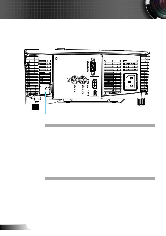
P109, IN112xv, IN114xv, IN116xv
1 2
3 |
4 |
5 |
6 |
7 |
1.VGA-IN/YPbPr Connector (PC Analog Signal/Component
Video Input/HDTV/YPbPr)
2.HDMI1 Connector
3.Security Lock Slot
4.Composite Video Input Connector
5.S-Video Input Connector
6.USB Connector (Connect to PC for Remote Mouse function/USB Service for firmware upgrade)
7.Power Socket
English 10
Introduction
Remote Control
The interface is subject to model’s
specifications.
1
2
3
4
5
6
7
8
9
10
VG |
111. Source
2.Re-Sync
3.Video and S-Video
124. HDMI
135. 3D
6.Volume +/-
147. Four Directional Select
15Keys
68. Menu
9. AV Mute
1610. Mute
1711. IR LED
1412. Power On/Off
13. VGA
1814. Keystone +/- and Remote Mouse function
15.Aspect
16.Enter and Enable
Remote Mouse function
17.Zoom
18.Brightness Mode
11 English
Installation
Connecting the Projector
Connect to Computer/Notebook
P110, IN112xa, IN114xa, IN116xa
Monitor Output
Audio Output |
|
|
2 |
3 |
4 |
1 |
|
5 |
Due to the |
|
|
difference in |
|
molex |
applications for |
|
|
each country, |
|
|
some regions may |
|
|
have different |
|
|
accessories. |
|
6 |
|
|
(*) Not included
The interface is subject to model’s specifications .
|
7 |
|
8 |
1...................................................................................... |
*Audio Output Cable |
2............................................................................................. |
*VGA Out Cable |
3..................................................................................................... |
VGA Cable |
4.................................................................................................. |
*HDMI Cable |
5.................................................................................................... |
Power Cord |
6.................................................................................................... |
*USB Cable |
7................................................................................................ |
*RS232 Cable |
8......................................................................................... |
*Audio Input Cable |
English 12

Installation
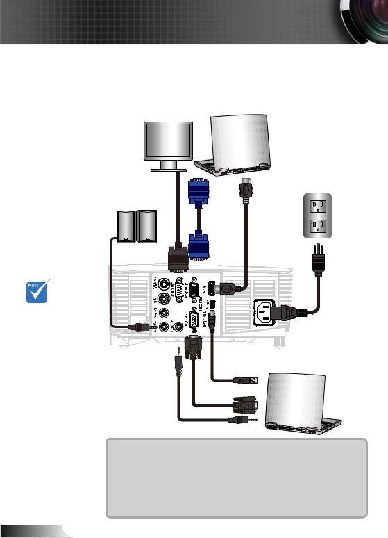
P109, IN112xv, IN114xv IN116xv
Monitor Output
1 |
2 |
3
Due to the |
|
difference in |
|
applications |
|
for each |
|
country, some |
molex |
regions may |
|
have different |
4 |
accessories. |
|
(*) Not included
The interface
is subject to model’s specifications .
1..................................................................................................... |
VGA Cable |
2.................................................................................................. |
*HDMI Cable |
3.................................................................................................... |
Power Cord |
4.................................................................................................... |
*USB Cable |
13 English

Installation
Connect to Video Sources
P110, IN112xa, IN114xa, IN116xa
Composite Video Output
|
|
|
|
|
|
|
|
|
|
|
|
|
|
|
|
|
DVD Player, Set-top Box, |
||||||||||||
|
|
|
|
|
|
|
|
|
|
S-Video Output |
|
||||||||||||||||||
|
|
|
|
|
|
|
|
|
|
|
|
HDTV receiver |
|||||||||||||||||
|
|
|
|
|
|
|
|
|
|
|
|
|
|
|
|
|
|
||||||||||||
|
|
|
|
|
|
|
|
|
|
|
|
|
|
|
|
|
|
|
|
|
|
|
|
|
|
|
|
|
|
|
|
|
|
|
|
|
|
|
|
|
|
|
|
|
|
|
|
|
|
|
|
|
|
|
|
|
|
|
|
|
|
|
|
|
|
|
|
|
|
|
|
|
|
|
|
|
|
|
|
|
|
|
|
|
|
|
|
|
|
|
|
|
|
|
|
|
|
|
|
|
|
|
|
|
|
|
|
|
|
|
|
|
|
|
|
|
|
|
|
|
|
|
|
|
|
|
|
|
|
|
|
|
|
|
|
|
|
|
|
|
|
|
|
|
|
|
|
|
|
|
|
|
|
|
|
|
|
|
|
|
|
|
|
|
|
|
|
|
|
|
|
|
|
|
|
|
|
|
|
1 |
2 |
|
3 |
|
4 |
|
8 |
Due to the |
|
|
|
|
|
difference in |
|
|
|
|
|
applications for |
|
|
|
|
|
each country, |
5 |
6 |
7 |
9 |
|
some regions may |
|||||
|
|
|
|
||
have different |
|
|
|
|
|
accessories. |
|
|
|
|
|
(*) Not included |
|
|
|
|
|
The interface is |
|
|
|
DVD Player, Set-top Box, |
|
subject to model’s |
|
Audio Output |
|
HDTV receiver |
|
specifications . |
|
|
|
||
|
|
|
|
||
|
1................................................................................ |
|
|
*Composite Video Cable |
|
|
2.............................................................................................. |
|
|
*S-Video Cable |
|
|
3.................................................................................................. |
|
|
*HDMI Cable |
|
|
4.................................................................................................... |
|
|
Power Cord |
|
|
5...................................................................................... |
|
|
*Audio Output Cable |
|
|
6......................................................................................... |
|
|
*Audio Input Cable |
|
|
7........................................................................................... |
|
|
*VGA/RCA Cable |
|
|
8................................................ |
|
*15-Pin to 3 RCA Component/HDTV Adaptor |
||
|
9............................................................................. |
|
|
*3 RCA Component Cable |
|
English 14

Installation
P109, IN112xv, IN114xv IN116xv
Composite Video Output
|
|
|
|
|
|
|
|
|
|
S-Video Output |
DVD Player, Set-top Box, |
|||||||||||||||||||
|
|
|
|
|
|
|
|
|
|
|||||||||||||||||||||
|
|
|
|
|
|
|
|
|
|
|
|
|
|
|
HDTV receiver |
|||||||||||||||
|
|
|
|
|
|
|
|
|
|
|
|
|
|
|
|
|
|
|
|
|
|
|||||||||
|
|
|
|
|
|
|
|
|
|
|
|
|
|
|
|
|
|
|
|
|
|
|
|
|
|
|
|
|
|
|
|
|
|
|
|
|
|
|
|
|
|
|
|
|
|
|
|
|
|
|
|
|
|
|
|
|
|
|
|
|
|
|
|
|
|
|
|
|
|
|
|
|
|
|
|
|
|
|
|
|
|
|
|
|
|
|
|
|
|
|
|
|
|
|
|
|
|
|
|
|
|
|
|
|
|
|
|
|
|
|
|
|
|
|
|
|
|
|
|
|
|
|
|
|
|
|
|
|
|
|
|
|
|
|
|
|
|
|
|
|
|
|
|
|
|
|
|
|
|
|
|
|
|
|
|
|
|
|
|
|
|
|
|
|
|
|
|
|
|
|
|
|
|
|
|
|
|
|
|
|
|
|
|
|
|
1
2 |
3 |
4 |
6 |
Due to the |
|
|
|
difference in |
|
|
|
applications for |
|
|
|
each country, |
5 |
7 |
|
some regions may |
|||
|
|
||
have different |
|
|
|
accessories. |
|
|
|
(*) Not included |
|
|
|
The interface is |
|
DVD Player, Set-top Box, |
|
subject to model’s |
|
HDTV receiver |
|
specifications . |
|
|
|
|
1................................................................................ |
*Composite Video Cable |
|
|
2.............................................................................................. |
*S-Video Cable |
|
|
3.................................................................................................. |
*HDMI Cable |
|
|
4.................................................................................................... |
Power Cord |
|
|
5........................................................................................... |
*VGA/RCA Cable |
|
|
6................................................ |
*15-Pin to 3 RCA Component/HDTV Adaptor |
|
|
7............................................................................. |
*3 RCA Component Cable |
15 English

English

Installation
Powering off the projector
1.Press the “ ” button on the remote control or on the control panel to turn off the projector.
The following message will be displayed on the screen.
Press the “ ” button again to confirm otherwise the message will disappear after 15 seconds. When you press for the second time, the projector will shut down.
2.The cooling fans continue to operate for about 10 seconds for the cooling cycle and the ON/STANDBY LED will Flash Green. When the ON/STANDBY LED lights solid Amber, the projector has entered standby mode.
If you wish to turn the projector back on, you must wait until the projector has completed the cooling cycle and has entered standby mode. Once in standby mode, simply press “
”button to restart the projector.
3.Disconnect the power cord from the electrical outlet and the projector.
4.Do not turn on the projector immediately following a power off procedure.
Contact the nearest service center if the projector displays these symptoms.
Warning Indicator
When the warning indicators (see below) come on, the projector will automatically shutdown:
“LAMP” LED indicator is lit red and if “On/Standby” indicator flashes amber.
“TEMP” LED indicator is lit red and if “On/Standby” indicator flashes amber. This indicates the projector has overheated. Under normal conditions, the projector can be switched back on.
“TEMP” LED indicator flashes red and if “On/Standby” indicator flashes amber.
Unplug the power cord from the projector, wait for 30 seconds and try again. If the warning indicator light up again, please contact your nearest service center for assistance.
17 English

Installation
Adjusting the Projected Image
Adjusting the Projector’s Height
The projector is equipped with elevator feet for adjusting the image height.
1.Locate the adjustable foot you wish to modify on the underside of the projector.
2.Rotate the adjustable ring clockwise to raise the projector or counter clockwise to lower it. Repeat with the remaining feet as needed.
Tilt-Adjustment Feet

 Tilt-Adjustment Ring
English 18

Installation
Adjusting the Projector’s Zoom / Focus
You may turn the zoom ring to zoom in or out. To focus the image, rotate the focus ring until the image is clear.
SVGA/XGA series: The projector will focus at distances from 3.94 to 39.36 feet (1.2 to 12.0 meters).
WXGA series: The projector will focus at distances from 3.28 to 32.8 feet (1 to 10 meters).
Zoom Lever
Focus Ring
Adjusting Projection Image Size
SVGA/XGA series: Projection Image Size from 27.5” to 302.8” (0.7 to 7.69 meters).
WXGA series: Projection Image Size from 27.3” to 299.5” (0.69 to 7.61 meters).
Top View
Projection Distance (D)
Side View
Screen
Screen (W)
Height
|
|
|
|
|
|
|
Screen |
|
|
|
Screen (H) |
||
|
|
|
|
|
|
|
|
|
|
|
|
|
|
Offset (Hd)
Diagonal
Width
Projection Distance (D)
19 English

Installation
16:10 |
|
|
|
|
Distance |
|
Distance |
Distance |
|
|
diagonal |
Height |
width |
Height |
Width |
Distance |
Offset |
Offset |
|||
screen |
inches |
inches |
meters |
meters |
Wide |
Tele feet |
Wide |
Tele |
meters |
inches |
feet |
meters |
meters |
||||||||
inches |
|
|
|
|
|
|
|
|
|
|
30 |
15.90 |
25.44 |
0.40 |
0.65 |
3.26 |
3.63 |
1.00 |
1.10 |
0.05 |
1.99 |
40 |
21.20 |
33.92 |
0.54 |
0.86 |
4.35 |
4.83 |
1.34 |
1.46 |
0.07 |
2.65 |
60 |
31.80 |
50.88 |
0.81 |
1.29 |
6.53 |
7.25 |
2.00 |
2.20 |
0.10 |
3.97 |
|
|
|
|
|
|
|
|
|
|
|
70 |
37.10 |
59.36 |
0.94 |
1.51 |
7.62 |
8.46 |
2.34 |
2.56 |
0.12 |
4.64 |
|
|
|
|
|
|
|
|
|
|
|
80 |
42.40 |
67.84 |
1.08 |
1.72 |
8.71 |
9.67 |
2.67 |
2.93 |
0.13 |
5.30 |
|
|
|
|
|
|
|
|
|
|
|
90 |
47.70 |
76.32 |
1.21 |
1.94 |
9.79 |
10.88 |
3.00 |
3.30 |
0.15 |
5.96 |
100 |
53.00 |
84.80 |
1.35 |
2.15 |
10.88 |
12.08 |
3.34 |
3.66 |
0.17 |
6.62 |
120 |
63.60 |
101.76 |
1.62 |
2.58 |
13.06 |
14.50 |
4.01 |
4.39 |
0.20 |
7.95 |
|
|
|
|
|
|
|
|
|
|
|
150 |
79.50 |
127.20 |
2.02 |
3.23 |
16.32 |
18.13 |
5.01 |
5.49 |
0.25 |
9.94 |
|
|
|
|
|
|
|
|
|
|
|
180 |
95.40 |
152.64 |
2.42 |
3.88 |
19.59 |
21.75 |
6.01 |
6.59 |
0.30 |
11.92 |
|
|
|
|
|
|
|
|
|
|
|
250 |
132.50 |
212.00 |
3.37 |
5.38 |
27.21 |
30.21 |
8.35 |
9.15 |
0.42 |
16.56 |
|
|
|
|
|
|
|
|
|
|
|
300 |
159.00 |
254.40 |
4.04 |
6.46 |
32.65 |
36.25 |
10.02 |
10.98 |
0.50 |
19.87 |
|
|
|
|
|
|
|
|
|
|
|
4:3 |
|
|
|
|
Distance |
|
Distance |
Distance |
|
|
diagonal |
Height |
width |
Height |
Width |
Distance |
Offset |
Offset |
|||
screen |
inches |
inches |
meters |
meters |
Wide |
Tele feet |
Wide |
Tele |
meters |
inches |
feet |
meters |
meters |
||||||||
inches |
|
|
|
|
|
|
|
|
|
|
30 |
18.03 |
24.04 |
0.46 |
0.61 |
3.91 |
4.31 |
1.19 |
1.31 |
0.07 |
2.70 |
|
|
|
|
|
|
|
|
|
|
|
40 |
24.04 |
32.05 |
0.61 |
0.81 |
5.21 |
5.74 |
1.59 |
1.75 |
0.09 |
3.61 |
|
|
|
|
|
|
|
|
|
|
|
60 |
36.06 |
48.08 |
0.92 |
1.22 |
7.81 |
8.61 |
2.38 |
2.63 |
0.14 |
5.41 |
|
|
|
|
|
|
|
|
|
|
|
70 |
42.07 |
56.09 |
1.07 |
1.42 |
9.11 |
10.05 |
2.78 |
3.06 |
0.16 |
6.31 |
80 |
48.08 |
64.10 |
1.22 |
1.63 |
10.42 |
11.49 |
3.18 |
3.50 |
0.18 |
7.21 |
90 |
54.09 |
72.12 |
1.37 |
1.83 |
11.72 |
12.92 |
3.57 |
3.94 |
0.21 |
8.11 |
|
|
|
|
|
|
|
|
|
|
|
100 |
60.10 |
80.13 |
1.53 |
2.04 |
13.02 |
14.36 |
3.97 |
4.38 |
0.23 |
9.01 |
|
|
|
|
|
|
|
|
|
|
|
120 |
72.12 |
96.15 |
1.83 |
2.44 |
15.62 |
17.23 |
4.76 |
5.25 |
0.27 |
10.82 |
|
|
|
|
|
|
|
|
|
|
|
150 |
90.14 |
120.19 |
2.29 |
3.05 |
19.53 |
21.53 |
5.95 |
6.56 |
0.34 |
13.52 |
180 |
108.17 |
144.23 |
2.75 |
3.66 |
23.44 |
25.84 |
7.14 |
7.88 |
0.41 |
16.23 |
250 |
150.24 |
200.32 |
3.82 |
5.09 |
32.55 |
35.89 |
9.92 |
10.94 |
0.57 |
22.54 |
|
|
|
|
|
|
|
|
|
|
|
300 |
180.29 |
240.38 |
4.58 |
6.11 |
39.06 |
43.07 |
11.91 |
13.13 |
0.69 |
27.04 |
|
|
|
|
|
|
|
|
|
|
|
This table is for user’s reference only.
English 20
 Loading...