

Page 1

TOTAL SPEAKER SOLUTIONS
TSS 3-IN-1
TSS 3-IN-1
Owner’s Guide
Page 2
INTRODUCTION
Couch
L
eft
S
urround Channel
(not included)
R
ight
S
urround Channel
(not included)
TSS 3-in-1
(
above or below TV)
I
nfinity
S
ubwoofer
(
not included)
PLANNING YOUR SYSTEM
Infinity Total Solutions
™
The Infinity Total Solutions TSS 3-in-1 loudspeaker is actually
three discrete loudspeakers built into a single enclosure.The
TSS 3-in-1 incorporates the front left,center and right channels
f a home theater system. Simply add a Total Solutions powered
o
subwoofer and satellites for the surround channels to complete
a high-performance home entertainment speaker system.The
TSS 3-in-1 uses identical drivers to provide exceptional dialogue
reproduction and a seamless transition between the front
hannels.The horizontal design allows for maximum placement
c
flexibility.
About This Guide
Please read this guide completely before connecting and
ating the TSS 3-in-1 center channel speaker.Maximum
oper
performance is dependent upon following these instructions,as
well as those in the owner’s manuals of associated components
in your home theater system. Save these instructions for future
reference.
Unpacking the Speaker
Finish unpacking the speaker and check the contents.If you
suspect damage from transit,report it immediately to your
dealer. Keep the shipping carton and packing materials for
future use.
Before deciding where to best place your speakers, survey your
oom and study Figures 1 and 2.The TSS 3-in-1 should be placed
r
directly above or below the TV.
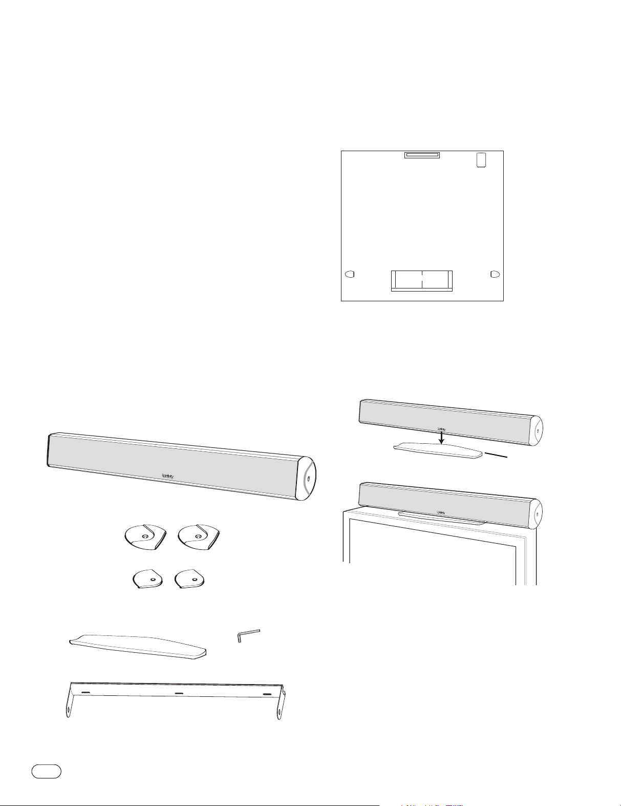
Figure 1.In this overhead view of a typical installation, the
TSS 3-in-1 is used to reproduce the front channels, and satellite
speakers are used to reproduce sound for the surround channels.
The powered subwoofer provides bass for movie effects and for
music.
Placement
Contents
Please verify that the package contains the following items:
(1) TSS 3-in-1 speaker
A
t
ar
P
t B
ar
P
all-mount end caps
W
(2)
(attached to TSS 3-in-1)
(1) Speaker base
(1) Allen
wrench
Speaker base
Figure 2.This example shows the TSS 3-in-1 being placed on
top of a television.The speaker can also be placed below the
ision and tilted up (see F
telev
TE: If placing the
NO
ision has a f
the top of the tele
v
accommodate the speaker base.
igure 3).
TSS 3-in-1 on top of a tele
ace lar
lat surf
Do not set the speaker on top
be sure
ision,
v
ge enough to
of any surface without using the included base.
(1) Wall bracket with wall bracket cover
2
TSS 3-IN-1
Page 3
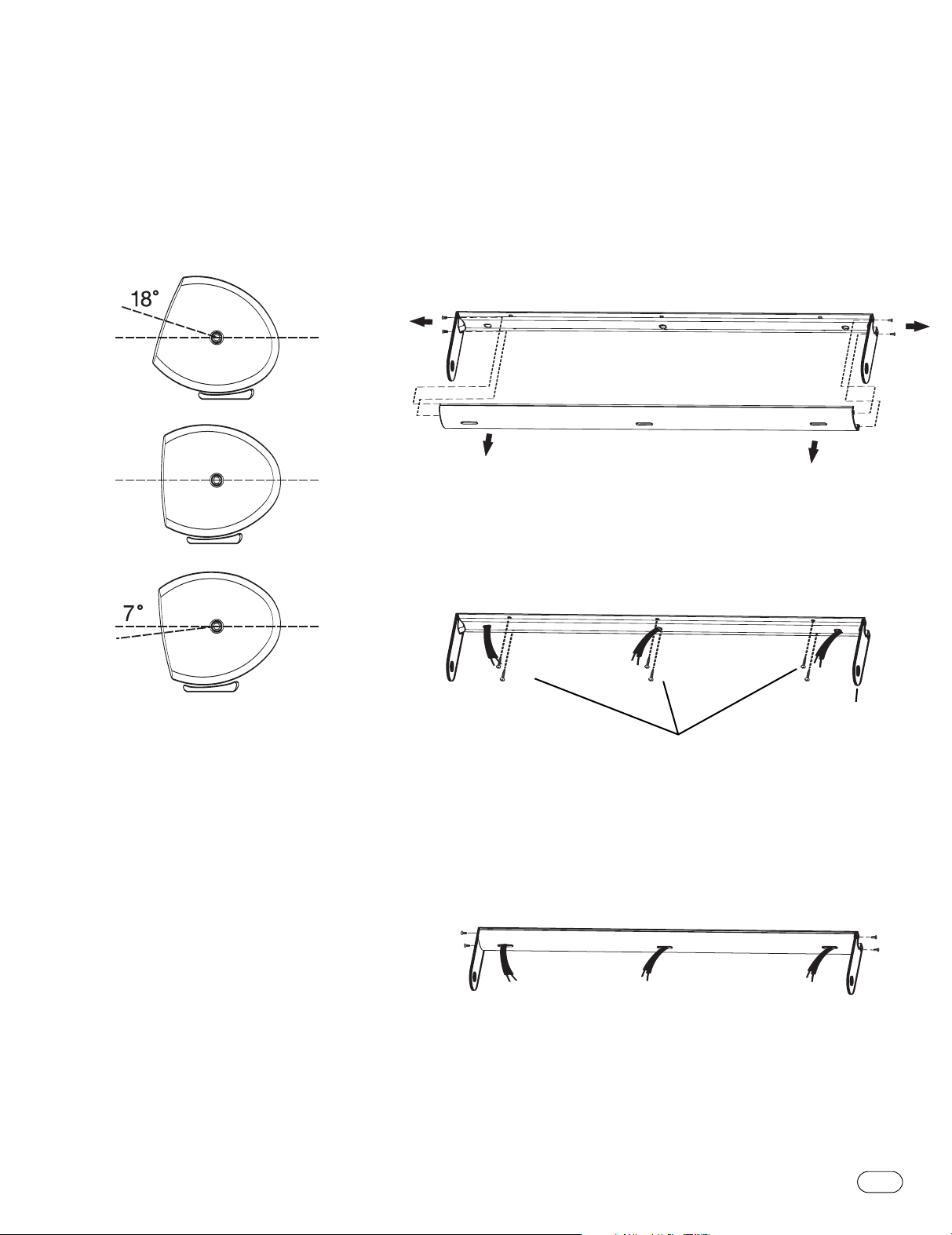
Tilting the Speaker
f needed, the enclosed stand allows you to tilt the speaker
I
across a wide range (i.e.,upward to a maximum of 18˚ or
ownward to a maximum of 7˚), as shown in Figure 3.
d
Important!
o not exceed the tilt range. Doing so may cause the speaker to
D
fall out of its stand.
Wall-Mounting the TSS 3-IN-1 Using the Included
Wall Bracket
The customer is responsible for proper selection and use of
ounting hardware,and for correctly and safely wall-mounting
m
the speakers.
Step One
Remove the wall bracket cover by removing the four wall-bracket
screws on the ends,as shown.
Step Two
Run the speaker wire for the left,center and right channels behind
the wall bracket and out the holes in the bracket.After deciding
where to place the speaker, attach the wall bracket (in a horizontal
position) to the wall using the appropriate screws and anchors.
Figure 3.
Mounting screws and
anchors not included
Step Three
Run the speaker wires out through the holes in the wall
bracket co
w
v
all bracket scr
Resecure in place
.
er
ws.
e
, as shown, with the four
W
all br
acket
TSS 3-IN-1
3
Page 4

Step Four
Using the included Allen wrench, remove the top and bottom
nd caps of the speaker by unscrewing the single center screw
e
on bottom.
nd cap
E
End cap
Step Six
he wall-bracket design allows for rotation of the speakers
T
at angles of up to 30 degrees of center. Position the speakers
o they face toward the primary listening position,before
s
fully tightening.
1/4-20 x 3/4"
Screw
Step Five
Connect the wires (see page 5).Replace the end caps while
capturing the wall bracket between parts A and B of the
securing it in place.
,
end cap
all-mount
W
end cap A
all-mount
W
end cap B
4
TSS 3-IN-1
Page 5

WIRING THE SPEAKER
– +
After placing the speaker, you are ready to connect it to your
system. First,turn off all audio system power.Use high-quality
speaker wire to make the connections.Consult the owner’s
anuals included with your amplifier or receiver for connection
m
and operation procedures.
2
1
Surround Modes
hen using the TSS 3-in-1 in a Dolby
W
theater system, make sure the receiver’s/processor’s front left,
front right and center channel speaker modes are set to “Small.”
®
igital or DTS
D
®
ome
h
Wiring and Polarity
The TSS 3-in-1 speaker has gold-plated terminals that can
accept bare wire.To ensure proper polarity,connect each
+ terminal on the back of the amplifier or receiver to the
respective + (red) terminal on each speaker,as shown in
Figure 4.Connect the – (black) terminals in a similar way.
See the owner’s manuals that were included with your
ier or receiver to confirm connection procedures.
amplif
Be sure to connect the left-channel wires to the left-most
terminals, the center channel wires to the middle terminals, and
the right-channel wires to the right-most terminals.
Important!
Do not reverse polarities (i.e., + to – or – to +) when making
connections. Doing so will degrade the imaging and bass
response of the home theater system.
After correctly placing and wiring the TSS 3-in-1 and the rest of
your speaker system, adjust the levels for all of the channels as
recommended by the manufacturer of your receiver/processor.
One channel shown.
igure 4.This example shows how to connect bare wires to the
F
terminals. Banana plugs may also be inserted directly into the
rear of the connector.
1 Loosen the terminals.
2 Insert bare ends; tighten terminals.
CARE OF YOUR SPEAKER SYSTEM
When needed, use a soft cloth to remove any fingerprints or
to wipe off dust. Do not use any cleaning products or polish.
Clean the grille by gentle vacuuming.
If your TSS 3-in-1 should ever need service,please contact your
local dealer or distributor, or visit www.infinitysystems.com for
the location of a service center.
TSS 3-IN-1
5
Page 6

SPECIFICATIONS
TSS 3-IN-1 Each Channel
Frequency Response 120 – 20kHz (±3dB)
Nominal Impedance 8 Ohms
Sensitivity 89dB
(2.83V @ 1m)
Recommended Amplifier 10 – 125 Watts
Power Range
Crossover Frequency
w-Frequency Drivers
Lo
3,500Hz; 24dB/octave
(2) 3-1/2" (89mm) MMD®,
magnetically shielded
High-Frequency Driver 3/4" (19mm) MMD,
elliptical waveguide,
magnetically shielded
Dimensions (H x W x D) 4-1/8" x 40-1/8" x 4-3/8"
(105mm x 1019mm x 111mm)
Weight 15.25 lb (6.9kg)
Infinity continually strives to update and improve existing products,as
well as create new ones.The specifications and construction details in
this and related Infinity publications are therefore subject to change
without notice.
Declaration of Conformity
6
TSS 3-IN-1
We, Harman Consumer Group International
2, route de Tours
72500 Château du Loir
France
declare in own responsibility that the product described in this
owner’s manual is in compliance with technical standards:
EN 61000-6-3:2001
EN 61000-6-1:2001
Laurent Rault
Harman Consumer Group International
Château du Loir, France 5/06
Page 7

NOTES
Page 8

inity Systems
Inf
Har
,
inity
Inf
Dolby is a r
ML-TS40LCR 5/06
.
t No
ar
P
© 2006 Har
man Inter
egister
man Inter
ademar
ed tr
national Industr
k of Dolby Labor
ies
DTS is a registered trademark of DTS,Inc.
.
ies
ator
ated.All rights reserved.
por
Incor
,
ark Drive,Woodbury, NY 11797 USA (516) 674-4463 (USAonly) www.infinitysystems.com
ys P
a
ossw
250 Cr
,
national and MMD are registered trademarks, and Total Solutions is a trademark, of Harman International Industries, Incorporated.
 Loading...