

Beta™ SW Series
SW-12 Subwoofer
PRELIMINARY SERVICE MANUAL
Infinity Systems, Inc.
250 Crossways Park Dr.
Woodbury, New York 11797

1
- CONTENTS -
BASIC SPECIFICATIONS …………………………………….…….……………..1
DETAILED SPECIFICATIONS ……………..……………………………….…..2
CONTROLS AND CONNECTIONS…………………………………….…..………..4
OPERATION….……………………………………………………………………..….6
BASS OPTIMIZATION SYSTEM…………………………………….……...………..7
EXTERNAL/MECHANICAL PARTS LIST …………….………………....……8
BLOCK DIAGRAM…………………………..…………………………………..…..…9
ELECTRICAL PARTS LIST (120v) ………………………………………………….10
ELECTRICAL PARTS LIST (230v) ………………………………………………….15
PCB DRAWINGS……………….…………..……………….…………………..….…20
SEMICONDUCTOR PINOUTS…………………………………….………….……..29
SCHEMATICS (120v)……………………………………………...………………...30
SCHEMATICS (230v)……………………………………………...………………...34
Basic S pecificat i ons
SW-12 Powered Subwoofer
Frequency Range: 28Hz – 150Hz (±3dB)
Max Amplifier Output: 500 watts RMS
Low-Frequency Driver: 12" (305mm) C.M.M.D.
Crossover Frequency: 50 -150 Hz (24dB/octave, continuously variable)
Dimensions (H x W x D): 16-3/4" x 14-7/8" x 19-7/8"
(425mm x 378mm x 505mm)
Weight: 45 lb (20.5 kg)
Infinity continually strives to update and i mprove exi sting products, as well as create new ones. The specifications
and construction details in this and relat ed Infi nity publications are t her efore subject to change without notice.

e
SW-12
2
SW-12 300W Powered Sub/ Plate Amp
LINE VOLTAGE Yes/No Hi/Lo Line Nom. Unit Notes
Parameter Specification Unit
Amp Section
Type (Class AB, D, other) D n/a
Load Impedance (speaker) 6 Ohms
Rated Output Power 250 Watts
THD @ Rated Power 0.1 %
THD @ 1 Watt 0.1 %
Dynamic Power 400 Watts
DC Offset 10 mV-DC
Damping factor >50 DF
Input Sensitivity
Input Frequency 30 Hz
L&R 14.7 mVrms
LP Off Mode selected 14.7 mVrms
US 120vac/60Hz Yes 108-132 120 Vrms Normal Operation
EU 230vac/50-60Hz Yes 207-264 230 Vrms Normal operation, MOMS required
QA Test
Limits Conditions Notes
Bridge type amplifier, None of the speaker
n/a
n/a
Nominal
225
1 input driven
1
22K filter
0.2
22K filter
Power is the average measurement
of the first consecutive cycles of the
380
burst signal
60
@ Speaker Outputs
23
Measured at amplifier board
30
Nominal Freq.
±2dB
To 1 Watt
±2dB
To 1 Watt
terminals must be connected to system GND at
any time.
Limiter prevents continuous power to exceed
240 Watts, amplifier delivering power in excess
of 300 Watts at 4 Ohms of load impedance.
3/20 Cycles @ 50 Hz, burst test into 4 Ohms,
input driven 6dB above its maximum sensitivity,
volume level at Maximum, RABOS Section OFF
Measured at the speaker cable. 200 Watts,
measured at speaker output terminals located at
the amp board.
Single input driven, Ap Zo=600 Ohms, LP ON,
RABOS OFF, Volume ctrl & crossover at max
Single input driven , Ap Zo=600 Ohms, LP OFF,
RABOS OFF, Volume ctrl & crossover at max
Speaker/Hi Level Input 0.206 Vrms
Signal to Noise
SNR-A-Weighted 100 dBA
SNR-unweighted 90 dBr
SNR rel. 1W-unweighted 60 dBr
Residual Noise Floor 0.5 mVrms
Residual Noise Floor 0.5 mVrms(max)
Input Impedance
Line Input (L, R,LFE) 10K ohms
Speaker/Hi Level Input 10K ohms
Filters
LP 4th order variable 50-150 Hz
Subsonic filter (HPF) 2nd Ord
Low pass filter OFF Fixed Hz
BOS
Frequency Control --
Range 20-80 Hz
Level Control -- -Range -14.1 to 0 dB
Width(Q) Control -- -Range 4.5% to 49.5% octave
Limiter
THD at Max. Output Power
Features --
Auto - On -Off YES -Phase switch 0-180 deg
Volume pot Taper (lin/log) LOG -Variable crossover 50-150 Hz YES
HP Speaker out YES
LP On- Off Select switch YES --
Fixed Hz
YES n/a functional
Single input driven, Ap Zo=25 Ohms, LP ON,
±2dB
To 1 Watt
90
Relative to rated power A-Weighting filter
85
Relative to rated power 22K filter
55
Relative to 1W Output 22K filter
Volume @max, using RMS reading
1
DMM/VOM (or A/P)
Volume @max, w/ A/P Swept
Bandpass Measurement (Line
1
freq.+ harmonics)
n/a
Nominal
n/a
Nominal
± 10
± 10
± 10 L or R input driven, LP Filter OFF
functional
functional
functional
functional
functional
functional
functional
functional Pass through from the speaker input section
functional Disables LP filter, intended for LFE
21 detent pot (0.1 oct. steps)
21 detent pot (0.5dB steps)
21 detent pot (5steps/0.1 octave)
RABOS OFF, Volume ctrl & crossover at max
No switch to select the ATO mode is provided,
Refer to ATO section
A Taper
4th Order LP Variable crossover
Input Configuration

SW-12
3
Parameter Specification Unit
Line In (L,R) & LFE YES --
Spkr/Hi Level In YES --
Signal Sensing (ATO)
Auto-Turn-On (yes/no) YES
ATO Input test frequency 50 Hz
ATO Level LFE Input 2 mV
ATO Level Speaker in 50 mV
ATO Turn-on time 2 seconds
Auto Mute/ Turn-OFF Time 15 minutes
Power on Delay time 3 sec.
Transients/Pops
ATO Transient 5 mV-peak
Turn-on Transient 50 mV-peak
Turn-off Transient 50 mV-peak
Efficiency
Efficiency 70 %
Stand-by Input Power 10
Stand-by Input Power 12 Watts
Power Cons. @ rated power 325 Watts
Protection
Short Circuit Protection YES
Thermal Protection YES
DC Offset Protection YES
Line Fuse Rating
USA-Domestic 4 Amps Type-T or Slo Blo-250 V
EU 2 Amps Type-T or Slo Blo-250 V Internal fuse with UL/SEMKO rated holder
QA Test
Limits Conditions Notes
functional Dual RCA jack, Lor R is used in LFE mode
functional
functional
functional
functional
functional
functional
17
4
n/a
1V-pk-pk
1V-pk-pk
65
10
15
338
functional
functional
-
Auto - on selection switch in Auto
"
"
"
Amp connected and AC on, then
input signal applied
(T) Time before muting, after input
signal is removed
AC Power Applied
@ Speaker Outputs
@ Speaker Outputs AC Line cycled from OFF to ON
@ Speaker Outputs AC Line cycled from ON to OFF
Rated power Nominal Line voltage 120 VAC
@ nominal line voltage, Amp in
OFF state, RED LED activated
@ nom. line voltage, Amp in On
state, Green LED activated
@ nom. line voltage 220 Watts @ 6.0 Ohms nominal line voltage
Direct short at output
@1/8 max unclipped Power
DC present at Speaker Out leads Relay opens duisng a DC output condition
Binding post connector L&R
Auto turn of time (T) must be 10 > T < 17 Minut
Maximum allowable input power LED in RED,
Class D inactive
Maximum allowable input power under nominal
Input voltage and frequency, in stand-by mode
(HOT or COLD operation, LED GREEN). Class
D active but no signal applied.
Amplifier should resume operation after short
circuit condition removal
Temperature rise in accessible metal parts
should not exceed 35K rise for domestic version
or 30K rise for European versions (refer to
requirements sheet). Unit is protected for overtemperature conditions
POWER
AC
120V ~ 60HZ
500W
OFF
ON
®
BASS OPTIMIZATION SYSTEM
FREQUENCY LEVEL
OFF
GREEN: ON
RED: STANDBY
PHASE
LINE LEVEL IN
HIGH
LEVEL
IN
HIGH
LEVEL
OUT
Infinity Systems
Northridge, CA USA
R L
+
_
R
L
R
L
180
0
50 150
CROSSOVER
MIN MAX
LEVEL
POWER
ON
WIDTH
CAUTION
RISK OF ELECTRIC SHOCK
DO NOT OPEN
WARNING:
TO REDUCE THE RISK OF FIRE OR ELECTRIC SHOCK,
DO NOT EXPOSE THIS APPLIANCE TO RAIN OR MOISTURE.
AVERTISSEMENT:
POUR PRÉVENIR LES RISQUES D'INCENDIE OU
DE CHOC ÉLECTRIQUE, ÉVITER D'EXPOSER CET APPAREIL A LA
PLUIE OU A L'HUMIDITÉ.
P/N:352153-001
SW-12
Normal
LFE
‹
‚
⁄
¤
ª
•
¶
§
∞
¢
£
™
¡
SW-12
4
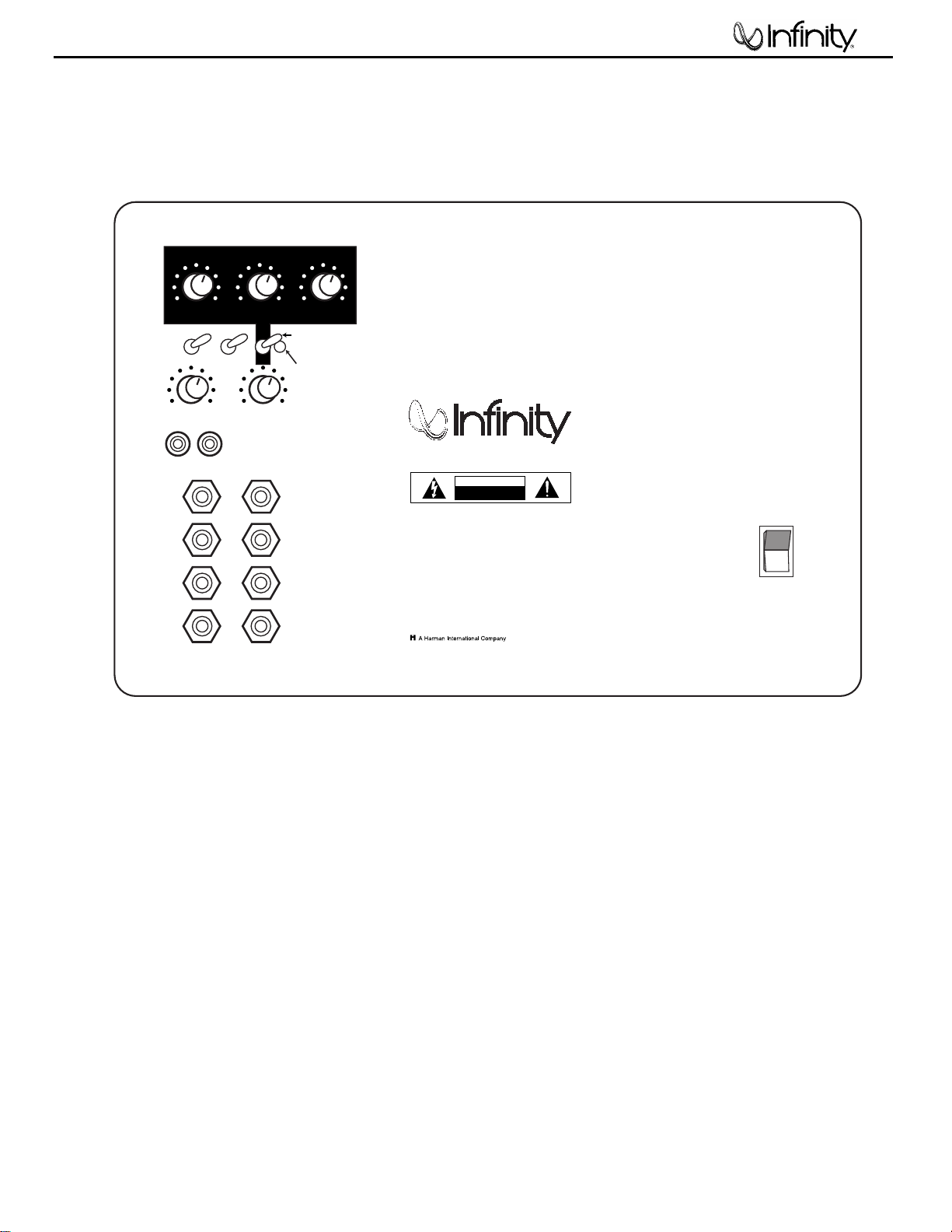
CONTROLS AND CONNECTIONS
Rear Panel
Bass Optimization Controls (see page 5)
¡
Bass Optimization System Selector
™
Center-Frequency Adjustment
£
Bass Optimization System Level Adjustment
¢
Bass Optimization System Bandwidth Adjustment
∞
Phase Switch
§
Normal/LFE Selector
¶
Power Indicator
•
Crossover Adjustment
ª
Subwoofer Level (Volume) Control
‚
Line-Level Inputs
⁄
High-Level (Speaker) Inputs
¤
High-Level (Speaker) Outputs
‹
Power Switch
SW-12
RECEIVER/AMPLIFIER
Front Speaker Output
BASS OPTIMIZATION SYSTEM
FREQUENCY
R L
1800Normal
0
LFE
POWER
AC
120V ~ 60HZ
500W
OFF
ON
®
LEVEL
OFF
GREEN: ON
RED: STANDBY
PHASE
LINE LEVEL IN
HIGH
LEVEL
IN
HIGH
LEVEL
OUT
Infinity Systems
Northridge, CA USA
+
_
R
L
R
L
50 150
CROSSOVER
MIN MAX
LEVEL
POWER
ON
WIDTH
CAUTION
RISK OF ELECTRIC SHOCK
DO NOT OPEN
WARNING:
TO REDUCE THE RISK OF FIRE OR ELECTRIC SHOCK,
DO NOT EXPOSE THIS APPLIANCE TO RAIN OR MOISTURE.
AVERTISSEMENT:
POUR PRÉVENIR LES RISQUES D'INCENDIE OU
DE CHOC ÉLECTRIQUE, ÉVITER D'EXPOSER CET APPAREIL A LA
PLUIE OU A L'HUMIDITÉ.
P/N:352153-001
SW-12
BASS OPTIMIZATION SYSTEM
FREQUENCY
R L
1800Normal
LFE
RECEIVER/PROCESSOR
POWER
AC
120V ~ 60HZ
500W
OFF
ON
®
LEVEL
OFF
GREEN: ON
RED: STANDBY
PHASE
LINE LEVEL IN
HIGH
LEVEL
IN
HIGH
LEVEL
OUT
Infinity Systems
Northridge, CA USA
+
_
R
L
R
L
50 150
CROSSOVER
MIN MAX
LEVEL
POWER
ON
WIDTH
CAUTION
RISK OF ELECTRIC SHOCK
DO NOT OPEN
WARNING:
TO REDUCE THE RISK OF FIRE OR ELECTRIC SHOCK,
DO NOT EXPOSE THIS APPLIANCE TO RAIN OR MOISTURE.
AVERTISSEMENT:
POUR PRÉVENIR LES RISQUES D'INCENDIE OU
DE CHOC ÉLECTRIQUE, ÉVITER D'EXPOSER CET APPAREIL A LA
PLUIE OU A L'HUMIDITÉ.
P/N:351153-001
SW-12
SUBWOOFER OR
LFE OUTPUT
POWER
AC
120V ~ 60HZ
500W
OFF
ON
®
BASS OPTIMIZATION SYSTEM
FREQUENCY LEVEL
OFF
GREEN: ON
RED: STANDBY
PHASE
LINE LEVEL IN
HIGH
LEVEL
IN
HIGH
LEVEL
OUT
Infinity Systems
Northridge, CA USA
R L
+
_
R
L
R
L
1800Normal
LFE
50 150
CROSSOVER
MIN MAX
LEVEL
POWER
ON
WIDTH
CAUTION
RISK OF ELECTRIC SHOCK
DO NOT OPEN
WARNING:
TO REDUCE THE RISK OF FIRE OR ELECTRIC SHOCK,
DO NOT EXPOSE THIS APPLIANCE TO RAIN OR MOISTURE.
AVERTISSEMENT:
POUR PRÉVENIR LES RISQUES D'INCENDIE OU
DE CHOC ÉLECTRIQUE, ÉVITER D'EXPOSER CET APPAREIL A LA
PLUIE OU A L'HUMIDITÉ.
P/N:352153-001
SW-12
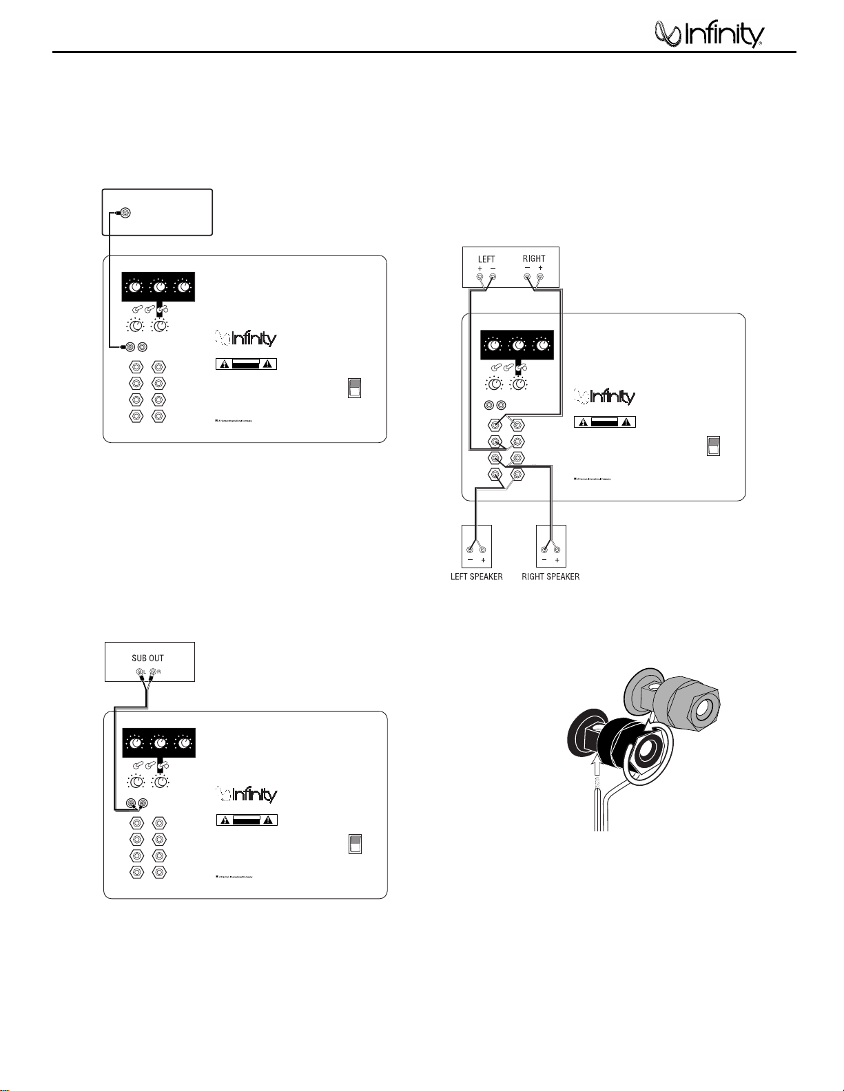
LOOSEN TERMINALS
INSERT BARE END;
TIGHTEN TERMINALS
1.
2.
BLACK =
–
STRIPE = –NO STRIPE =
+
RED =
+
SW-12
5
CONNECTIONS
If you have a Dolby* Digital or DTS®receiver/processor
with a low-frequency-effects (LFE) output:
• Set Normal/LFE Switch to LFE.
NOTE: In this case, you do not need to use a Y connector. Simply
connect the LFE output on your receiver/processor to either the left
or right input on the subwoofer.
If your receiver/amplifier does not have subwoofer
outputs for the left and right channels or an LFE
output:
If your receiver/processor has subwoofer
outputs for the left and right channels:
• Set Normal/LFE Switch to Normal.
NOTE: Some receivers have a single subwoofer output (do not confuse
this with a single LFE output as described below). In that case, it is
recommended that you use a Y connector (not included) to maximize
performance.
• Set Normal/LFE Switch to Normal.
SW-12

SW-12
6
OPERATION
Power On
Plug your subwoofer’s AC cord into a wall outlet. Do not use the
outlets on the back of the receiver.
Initially set the Subwoofer Level (Volume) Control ªto the
“min” position.
Turn on your sub by pressing the Power Switch ‹on the
rear panel.
Crossover Adjustments
NOTE: This control will have no effect if the Normal/LFE Selector
Switch § is set to “LFE.”If you have a Dolby Digital or DTS
processor/receiver, the Crossover Frequency is set by the
processor/receiver. Consult your owner’s manual to learn how
to view or change this setting.
Auto On/Standby
With the Power Switch ‹in the ON position, the Power
Indicator LED ¶will remain backlit in red or green to
indicate the On/Standby mode of the subwoofer.
RED = STANDBY (No signal detected,Amp Off)
GREEN = ON (Signal detected, Amp On)
The subwoofer will automatically enter the Standby mode after
approximately 10 minutes when no signal is detected from your
system.The subwoofer will then power ON instantly when a
signal is detected. During periods of normal use, the Power
Switch ‹can be left on.You may turn off the Power Switch
for extended periods of nonoperation, e.g., when you are away
on vacation.
‹
Adjust Gain
Turn on your entire audio system and start a CD or movie
soundtrack at a moderate level.Turn up the Subwoofer Level
(Volume) Control ªabout half way. If no sound emanates from
the subwoofer, check the AC-line cord and input cables. Are the
connectors on the cables making proper contact? Is the AC
plug connected to a “live”receptacle? Has the Power Switch
been pressed to the “On” position? Once you have confirmed that
the subwoofer is active, proceed by playing a CD, record or
cassette. Use a selection that has ample bass information.
Set the overall volume control of the preamplifier or stereo to a
comfortable level. Adjust the Subwoofer Level (Volume) Control
until you obtain a pleasing blend of bass. Bass response should
not overpower the room but rather be adjusted so there is a
harmonious blend across the entire musical range. Many users
have a tendency to set the subwoofer volume too loud,
adhering to the belief that a subwoofer is there to produce lots
of bass.This is not entirely true. A subwoofer is there to enhance
bass, extending the response of the entire system so the bass
can be felt as well as heard. However, overall balance must
be maintained or the music will not sound natural. An
experienced listener will set the volume of the subwoofer so
its impact on bass response is always there but never obtrusive.
‹
ª
The Crossover Adjustment Control • determines the highest
frequency at which the subwoofer reproduces sounds. If your main
speakers can comfortably reproduce some low-frequency sounds,
set this control to a lower frequency setting, between 50Hz
and 100Hz.This will concentrate the subwoofer’s efforts on the
ultradeep bass sounds required by today’s films and music. If you
are using smaller bookshelf speakers that do not extend to the
lower bass frequencies, set the Crossover Adjustment Control to
a higher setting, between 120Hz and 150Hz.
Phase Control
The Phase Switch ∞ determines whether the subwoofer
speaker’s piston-like action moves in and out with the main
speakers, 0,˚ or opposite the main speakers, 180˚.Proper phase
adjustment depends on several variables such as room size,
subwoofer placement and listener position.Adjust the phase
switch to maximize bass output at the listening position.
SW-12

To solve a problem, it helps to first identify whether you have
one and, if so, what it is. First, play a variety of music and
films with energetic bass sounds, like bass guitar, kick drum,
keyboards, etc. A kick drum should produce a tight “thump”, not a
flabby“boom.”Bass melody or harmony lines should have notes
that are about equally loud. If some notes disappear, or stand out
because they are consistently too loud, there is a problem.
Disappearing notes have to be handled by moving the listening
position, or the loudspeakers, to slightly different locations.
Often, but sadly not always,this will be enough. Excesses in
bass tend to be most annoying, and energetic resonances that
cause “boomy” or “lumpy” bass can be truly aggravating over a
period of time. Infinity’s Bass Optimization System can fix this.
So, the first step is to exercise your music collection, and listen
for low-frequency problems that crop up in several different
recordings.Something that only happens in one recording is
likely to be a problem in the recording – it happens! If you
identify something that is consistently wrong, select a record
that shows it very clearly, and put your CD/DVD player into a
repeat mode (A-B repeat is especially helpful, because you can
isolate a short musical passage).
Set the Bass Optimization System Bandwidth Adjustment Control
¢
to a middle position (10 clicks from a fully clockwise
position) and set the Level Adjustment £ for a –6dB (8 clicks
from a fully clockwise position).Then, while the music is playing,
sit in your favorite chair and have somebody else slowly adjust
the Center-Frequency control ™ from fully clockwise to fully
counterclockwise.At a certain frequency, you should hear the
problem lessen and the overall bass performance improve.When
you are satisfied that you have found the best frequency, have
your assistant vary the Level £ slowly up and down until you
have maximized the improvement. If you have really keen ears,
you can also have the Bandwidth Adjustment control ¢adjusted
for maximum benefit.
While the Bass Optimization System allows the listener to finetune the bass response to sound best in a particular room, some
listeners don’t have the skill or desire to adjust their system by
ear. In order to facilitate quicker and more accurate results,
Infinity has developed an optional test and measurement kit that
allows the user to perform a series of measurements and aids
him/her in properly setting the Bass Optimization System
controls.With the addition of this kit, the Bass Optimization
System becomes truly room-adaptive.The kit consists of the
following: a test CD,a sound-level meter that is specifically
calibrated for low frequencies, and something we call a “Q-Finder,
”
a device to help find the width of the measured curve and,
finally, a measurement template. It works as follows.The listener
plays the tones from the test CD and records the relative output
level of each test tone,using the sound-level meter, on the
provided measurement template.After all the tones are complete,
the template contains a response curve for the frequencies
below 100Hz.The user simply notes the frequency of the largest
bass peak, calculates the correct amount of attenuation, and
uses the
“Q-Finder
”to determine the width of the curve.These
three values are dialed into the Bass Optimization System
controls located on the speaker. The entire process takes less
than twenty minutes.
If your dealer does not stock the Bass Optimization System test
and measurement kit, you may purchase it directly from Infinity.
U.S. residents can visit our Web site at www.infinitysystems.com
or call 1.516.674.4INF.
MAINTENANCE AND SERVICE
SW-12
7
BASS OPTIMIZATION SYSTEM
Infinity’s Bass Optimization System is a simple-to-use, yet
sophisticated, low-frequency calibration system.The subwoofer
contains a parametric equalizer that you can adjust following the
directions below. By following these instructions, you can improve
the sound of your system.
™
The Bass Optimization System Goal
It is a fact of audio that what we hear at low frequencies is
determined as much or more by the listening room than by the
loudspeaker itself. Placement of the loudspeakers and listeners
and the acoustical characteristics of the room surfaces are all
important determinants of bass quantity and quality. In most
practical situations, there is little that can be done about this,
except for patient trial-and-error repositioning of the loudspeakers and listeners. Usually, the practical constraints of
a living space and the impracticality of massive acoustical
treatment mean that equalization is the only practical solution.
Professional sound engineers routinely employ sophisticated
measurement systems and equalizers to optimize speakers to the
installation.This was never practical for the home audiophile.
This is why the Bass Optimization System was created. It
enables you to identify the dominant low-frequency response
characteristic of your room. Once you know the problem, the Bass
Optimization System provides the tools needed to optimize the
low-frequency characteristics of the speakers to the room they
are in, exactly as the professional sound engineers do it.
Preparations
Before beginning the bass tests, please check the following:
• Make sure all three Bass Optimization System controls on the
subwoofer are turned fully clockwise.
• Make sure the loudness contour (if any) on your receiver/
processor/preamp is turned off.
• Set the receiver’s/processor’s tone controls (Bass and Treble)
to their center or flat positions.
• Bypass all surround and effects features of your receiver/
processor/preamp or set to Stereo Bypass.
• If you are using a multichannel surround processor or
receiver, make sure all bass-management features are properly
set.The Audio channels should all be set to “Small”or “HighPass” and the subwoofer set to “On.”
• Set the Bass Optimization System Selector ¡ to “On.”
For best results, it is recommended that all major furnishings
are in place and that all doors and windows in the listening area
are in their normal positions.That is, if you normally listen to
music with all doors closed, then this is how they should be
during this procedure.
SW-12

SW-12
8
SW-12 EXTERNAL/MECHANICAL PARTS LIST
Part Number Description Qty
Not For Sale SW-12 AMPLIFIER 1 EA
Not For Sale SW-12 CABINET 1 EA
351942-001 TRIM RING, 12" - SW-12 (BLACK) 1 EA
351942-001 TRIM RING, 12" - SW-12 (BEECH) (CHERRY)
333249-001 CUP, G RILLE (BLACK ) 4 EA
333249-003 CUP, GRILLE (BEECH) (CHERRY)
351617-001 LOGO - SW- 12 1 EA
338037-002 FOOT ASS’Y, RUBBER, BLK W/ THREADED INSERT 4 EA
72216 SCR, 8 X ¾, PAN,PH,PB,BLK ZINC,LCS WFR (BLACK) 6 EA
903802-016 SCR, 8 X ¾, PAN,PH,PB,BLK ZINC,LCS WFR (BEECH) (CHERRY)
882-41110-12 SCR, 6 X ¾,PAN,P H,PB,B LK ZI NC,LCS AMPLIFIE R 10 EA
351511-001 W OOFER,12",SUB DCR = 3.4 ohms ±10% 1 EA
352050-003 ASY,GRILLE, BLK, FRNT, SW-12 (BLACK) 1 EA
352050-004 ASY,GRILLE, BLK, FRNT, SW-12 (BEECH) (CHERRY)
352179-001 PORT TUBE SW-12 1 EA
Package
Part Number Description Qty
352050-003 ASY,GRILLE, BLK, FRNT, SW-12 (BLACK) 1 EA
352050-004 ASY,GRILLE, BLK, FRNT, SW-12 (BEECH) (CHERRY)
352614-001 MANUAL, OW NE RS – SW-12 1 EA
352151-001 CARTO N, OUTE R – SW-12 (BLACK) 1 EA
352151-002 CARTON, OUTER – SW-12 (BEECH)
352151-003 CARTO N, OUTE R – SW-12 (CHERRY)
352152-001 PAD,E ND,T OP & BOT- SW - 12 2 EA
352004-001 W ARRANTY, CA RD, 3/ 5Y R,I NFI NIT Y 1 EA
338076-001 SPIK E FOOT SET 1 set

SW-12
9
SW-12
10
SW-12 120V Electrical parts list
Part number Description Reference Designator
Resistors
021-100398-100 Metal Film Resistor 100R 1/8W F R339
021-100401-020 MOF Resistor 1K 1W J FK TYPE R173
021-100498-100 Metal Film Resistor 1K 1/8W F R363,381
021-100598-100 Metal Film Resistor 10K 1/8W F R338,342,343,346,348,353,
021-100698-100 Metal Film Resistor 100K 1/8W F R383
021-100798-100 Metal Film Resistor 1M 1/8W F R356
021-100898-100 Metal Film Resistor 10M 1/8W F R362
021-110698-100 Metal Film Resistor 110K 1/8W F R347
021-121598-100 Metal Film Resistor 12K1 1/8W F R354,369
021-140598-100 Metal Film Resistor 14K 1/8W F R380
021-150198-100 Metal Film Resistor 1K5 1/8W F R341
021-162398-100 Metal Film Resistor 162R 1/8W F R384
021-220598-100 Metal Film Resistor 22K 1/8W F R382
021-267498-100 Metal Film Resistor 2K67 1/8W F R336
021-340398-100 Metal Film Resistor 340R 1/8W F R357,371
021-357498-100 Metal Film Resistor 3K57 1/8W F R335
021-430498-100 Metal Film Resistor 4K3 1/8W F R204
021-470305-021 MOF Resistor 470R 5W J R78
021-549398-100 Metal Film Resistor 549R 1/8W F R344
021-560305-020 MOF Resistor 560R 5WS J 8x25 R76
021-619498-100 Metal Film Resistor 6K19 1/8W F R359,374
021-620598-100 Metal Film Resistor 62K 1/8W F R214
021-680398-100 Metal Film Resistor 680R 1/8W F R360
021-787398-100 Metal Film Resistor 787R 1/8W F R350,364
021-909398-100 Metal Film Resistor 909R 1/8W F R385
021-931498-100 Metal Film Resistor 9K31 1/8W F R351
022-005105-020 Resistor PN:SQM 0R05 5W J 25x13 R2
024-000097-120 SMD Resistor 0R 1/4W J 1206 R301-303,309,296,297
024-000098-120 SMD Resistor 0R 1/8W J 0805 R8,193
024-000098-120 SMD Resistor 0R 1/8W J 0805 R313,314,318,320
024-100298-120 SMD Resistor 10R 1/8W J 0805 R89,90,140,150
024-100398-121 SMD Resistor 100R 1/4W J 1206 R249
024-100498-120 SMD Resistor 1K 1/8W J 0805 R110
024-100498-120 SMD Resistor 1K 1/8W J 0805 R81,85,96,97,131,137,142,
024-100498-121 SMD Resistor 1K 1/4W J 1206 R238,264
024-100598-101 SMD Resistor 10K 1/4W F 1206 R200B,201B,218B,219B,298
024-100598-120 SMD Resistor 10K 1/8W J 0805 R5,7,16,118,121,122,125,1,
024-100598-120 SMD Resistor 10K 1/8W J 0805 R75,82,83,92,98,132,133,
024-100598-121 SMD Resistor 10K 1/4W J 1206 R202,205-207,212,217,222,
024-100698-101 SMD Resistor 100K 1/8W F 1206 R200,201,218,219
024-100698-120 SMD Resistor 100K 1/8W J 0805 R15,120
024-100798-120 SMD Resistor 1M 1/8W J 0805 R32,33
024-110598-120 SMD Resistor 11K 1/8W J 0805 R187,188,190,191
024-110598-120 SMD Resistor 11K 1/8W J 0805 R74,99
024-120498-120 SMD Resistor 1K2 1/8W J 0805 R189,192
024-130498-100 SMD Resistor 1K3 1/8W F 0805 R119

SW-12
11
Part number Description Reference Designator
024-150498-121 SMD Resistor 1K5 1/4W J 1206 R251
024-150598-120 SMD Resistor 15K 1/8W J 0805 R20,21
024-150598-121 SMD Resistor 15K 1/4W J 1206 R223
024-160598-100 SMD Resistor 16K 1/8W F 0805 R13,13B
024-200598-120 SMD Resistor 20K 1/8W J 0805 R95,141
024-200598-121 SMD Resistor 20K 1/4W J 1206 R256
024-220298-120 SMD Resistor 22R 1/8W J 0805 R28,29
024-220398-120 SMD Resistor 220R 1/8W J 0805 R136,167
024-220498-121 SMD Resistor 2K2 1/8W J 0805 R17,31
024-220498-121 SMD Resistor 2K2 1/8W J 0805 R134
024-220598-120 SMD Resistor 22K 1/8W J 0805 R127
024-220598-120 SMD Resistor 22K 1/8W J 0805 R37
024-220798-120 SMD Resistor 2M2 1/8W J 0805 R87,93
024-226598-100 SMD Resistor 22K6 1/4W F 1206 R208,209,231,232
024-237597-100 SMD Resistor 23K7 1/4W F 1206 R281
024-270498-120 SMD Resistor 2K7 1/8W J 0805 R80,84,157
024-270498-121 SMD Resistor 2K7 1/4W J 1206 R237
024-300398-121 SMD Resistor 300R 1/4W J 1206 R258
024-300598-121 SMD Resistor 30K 1/4W J 1206 R260
024-330498-101 SMD Resistor 3K3 1/4W F 1206 R203,215
024-330498-120 SMD Resistor 3K3 1/8W J 0805 R77,79,22,169
024-330498-121 SMD Resistor 3K3 1/4W J 1206 R240
024-330598-120 SMD Resistor 33K 1/8W J 0805 R4,6,60,60B
024-390498-120 SMD Resistor 3K9 1/8W J 0805 R130,161
024-390598-120 SMD Resistor 39K 1/8W J 0805 R86,94
024-412498-100 SMD Resistor 4K12 1/8W F 0805 R63
024-430598-120 SMD Resistor 43K 1/8W J 0805 R14
024-470298-120 SMD Resistor 47R 1/8W J 0805 R24-27
024-470398-120 SMD Resistor 470R 1/8W J 0805 R145,155,177,186
024-470398-120 SMD Resistor 470R 1/8W J 0805 R91
024-470498-120 SMD Resistor 4K7 1/8W J 0805 R151-153,183,34,36
024-470498-121 SMD Resistor 4K7 1/4W J 1206 R210
024-470598-120 SMD Resistor 47K 1/8W J 0805 R3,171
024-470598-120 SMD Resistor 47K 1/8W J 0805 R35
024-470598-120 SMD Resistor 47K 1/8W J 0805 R280,283
024-470698-121 SMD Resistor 470K 1/4W J 1206 R259
024-470798-121 SMD Resistor 4M7 1/4W J 1206 R243 ,244
024-510398-121 SMD Resistor 510R 1/4W J 1206 R261
024-510498-120 SMD Resistor 5K1 1/8W J 0805 R48A,48B,48C,48D,48E
024-560498-120 SMD Resistor 5K6 1/8W J 0805 R30
024-560598-120 SMD Resistor 56K 1/8W J 0805 R38
024-560598-121 SMD Resistor 56K 1/4W J 1206 R224
024-620398-121 SMD Resistor 620R 1/4W J 1206 R221,226
024-680498-120 SMD Resistor 6K8 1/8W J 0805 R23
024-680498-120 SMD Resistor 6K8 1/8W J 0805 R135,166
024-680498-121 SMD Resistor 6K8 1/4W J 1206 R247
024-680598-121 SMD Resistor 68K 1/4W J 1206 R250
024-820598-121 SMD Resistor 82K 1/4W J 1206 R263
025-010300-000 Thermister TSE-103 K L:50mm TH1
026-100595-001 VR 10KAx2 XV012311YGPJ25F15A10K-21PC/1 VR302,303
026-100595-002 VR 10KCx2 XV012311YGPJ25F15C10K-21PC/1 VR301

SW-12
12
Part number Description Reference Designator
026-500595-254 VR 50KA P/N:RK163111R405-EJ R216
026-500595-267 VR 50KBx4 PN:RD1631411001D-50KBx4 (EJ) R233
Capacitors
031-100184-100 SMD Capacitor 0u01/250V K 0805 X7R C104,119
031-100244-100 SMD Ceramic Capacitor 0u01/50V K 0805 X7R C27,28
031-100244-100 SMD Ceramic Capacitor 0u01/50V K 0805 X7R C108,118,131,140
031-100244-101 SMD Capacitor 0u01/50V K 1206 X7R C12,13,224,280
031-100343-100 SMD Capacitor 100pF/50V J 0805 NPO C81,84
031-100344-100 SMD Capacitor 0u1/50V K 0805 X7R C10,69,112,115,135,138
031-100344-100 SMD Capacitor 0u1/50V K 0805 X7R C75-78,82,85
031-100344-102L SMD Capacitor 0u1/50V K 1206 X7R C227,229,230,232-235
031-100344-104 SMD Capacitor 100pF/50V K NPO 1206 C204,222
031-100345-300 SMD Capacitor 0u1/50V M 1206 X7R C305,306
031-100384-100R SMD Capacitor 0u1/250V K 1206 X7R C5,6
031-180344-100 SMD Capacitor 0u18/50V K 0805 X7R C80,83
031-220344-103 SMD Capacitor 220pF/50V K NPO 1206 C200,210,215,216
031-220344-300 SMD Capacitor 220pF/50V K 0805 NPO C40
031-330445-100 SMD Capacitor 3300pF/50V M 1206 X7R C281
031-470144-101 SMD Capacitor 0u0047/50V K 0805 X7R C1G1
031-470244-102 SMD Capacitor 0u047/50V K 0805 X7R C93,94,101,124
031-470444-101 SMD Capacitor 4700pF/50V K X7R 1206 C2G1
031-560243-100 SMD Capacitor 56pF/50V J 0805 NPO C92,102,105,125
031-560343-102 SMD Capacitor 560pF/50V J 0805 NPO C79
031-680444-100 SMD Capacitor 6800pF/50V K X7R 1206 C212
032-100484-200 END Mylar Capacitor 1uF/250V K P:15 C37,39,30
033-330444-270 NPE Capacitor 3u3/50V K10 (R)8x13 SBE C114,137
033-680464-270 NPE Capacitor 6u8/100V K10 (R)1020 GNE C113,136
034-100515-300G Electrolytic Capacitor 10uF/16V M (R)0511 P:2 C220
034-100614-300 Electrolytic Capacitor 100uF/16V M (R)0611 P:2.5 C8
034-100615-301 Electrolytic Capacitor 100uF/16V M (R)0611 P:5 C221
034-100625-300 Electrolytic Capacitor 100uF/25V M (R)6.3x11 P:5 C62
034-100625-303 Electrolytic Capacitor 100uF/25V M (R) P:2.5 C117
034-100695-300 Electrolytic Capacitor 100uF/63V M (R)1012 P:5 C142
034-100715-202 Electrolytic Capacitor 1000uF/16V M (R)1017 P:5 C109,132
034-100895-204 Electrolytic Capacitor 10000uF/63V M (R)30x51 C1,4
034-220516-301 Electrolytic Capacitor 22uF/16V M (R)0511 P:2 C223,225
034-220525-300 Electrolytic Capacitor 22uF/25V M (R)5x11 P:2.5 C25,26
034-220525-300 Electrolytic Capacitor 22uF/25V M (R)5x11 P:2.5 C303,304,14,15
034-330615-301 Electrolytic Capacitor 330uF/16V M (R)0812 P:3.5 C32
034-330625-300 Electrolytic Capacitor 330uF/25V M (R)1013 P:5 C11,100
034-470415-300 Electrolytic Capacitor 4u7/50V M (R)0511 P:2.0 C7
035-100363-300 PE Capacitor 0u1/100V J P:5m/m C322,323,328
035-220243-100 PE Capacitor 0u022/63V J P:5m/m C202
035-330293-300 PE Capacitor 0u033/63V J P:5 C209,218
035-330393-300 ESK Mylar Capacitor 0u33/63V J P:5 C207,208
035-680253-300 PE Capacitor 0u068/63V J P:5m/m C201,213,380,381
039-220180-100 Safety Capacitor 18x16.5x8.5mm PN:XG275M224VHS2 CXAC1
SW-12
13
Part number Description Reference Designator
Semiconductors
050-505200-001 LED PN:LT-2402-21 LED1
051-000600-100 NPN Transistor PN:MPSW06RLRA TO-92 (ON) Q6
051-000600-100 NPN Transistor PN:MPSW06RLRA TO-92 (ON) Q31
051-005600-100 PNP Transistor PN:MPSW56RLRA TO-92 (ON) Q8
051-222200-100 NPN Transistor PN:MPS2222ARLRA TO-92 Q20,22
051-290700-100 PNP Transistor PN:MPS2907A RLRA TO-92 Q12,14,16,18
051-540101-000 PNP Transistor PN:2N5401 TO-92 Q3
051-555100-000 NPN Transistor PN:2N5551 TO-92 Q21,23
051-640001-000 Mosfet N-Channel PN:IRF640N TO-220 (IR) Q11,13,15,17
052-400080-000 Bridge Regulator PN:RS804 400V,8A BR1
053-211100-000 IC;DIP,Driver PN:IR2111 8PIN (IR) U7,8
053-257400-100 IC;DIP,Regulator PN:LM2574 HVN-15V 8PIN (NS) U6
054-000100-100 SMD Diode PN:ES1D 200V 1A D1,23,37,40,44,47
054-000100-100 SMD Diode PN:ES1D 200V 1A D35,43
054-001002-100 SMD Zener Diode PN:BZX84C10 10V SOT-23 D32
054-001002-100 SMD Zener Diode PN:BZX84C10 10V SOT-23 D42,49
054-001501-100 SMD Zener Diode PN:BZX84C15 15V SOT-23 D2,3
054-005501-100 SMD Zener Diode PN:BZV55C3V6 (PHILIPS) D60
054-007200-100L SMD IC; PN:M072M-TE1 DMP8 (JRC) U9,10
054-007200-100L SMD IC; PN:M072M-TE1 DMP8 (JRC) U200-205,301
054-007400-100 SMD IC;(OP) PN:TL074CDR (TI) U300
054-011400-100 SMD Transistor PN:DTC114TKA SMT3 (ROHM Q202
054-033904-100 SMD Transistor PN:MMBT3904LT1 SOT23 (ON Q25,28,29,37,50,51
054-033904-100 SMD Transistor PN:MMBT3904LT1 SOT23 (ON Q203,204
054-033906-100 SMD Transistor PN:MMBT3906LT1 SOT23 (ON Q26,27,30,36,52
054-033906-100 SMD Transistor PN:MMBT3906LT1 SOT23 (ON Q34,35
054-050601-100 SMD Zener Diode PN:BZX84C5V6 5.6V SOT-23 TAPIN D30
054-050601-100 SMD Zener Diode PN:BZX84C5V6 5.6V SOT-23 TAPIN Z7,8
054-414803-100 SMD Diode PN:LL4148 (Wishay) D4-5,13,14,21,22,31,33,38,
054-414803-100 SMD Diode PN:LL4148 (Wishay) D36,39,46,52,61
054-414803-100 SMD Diode PN:LL4148 (Wishay) D200-205,207,209,212,216,
054-540100-100 SMD Transistor PN:MMBT5401 LT1 SOT-23 Q1
054-540100-100 SMD Transistor PN:MMBT5401 LT1 SOT-23 Q33,40
054-555100-100 SMD Transistor PN:MMBT5551 LT1 (ON) Q2
054-555100-100 SMD Transistor PN:MMBT5551 LT1 (ON) Q32
Miscellaneous
061-001021-000 Knob PN49001-WD7 φ16x14 VR301-303
061-001052-000 Knob PN:49001-W D=15.1 H=14.5 R233,216
061-100016-000 Partition Post PN:BCMS-8 L=8mm Nylon 66(UL)
061-314002-000 Strain Relief P/N SB4F-2 PANEL,COVER
061-700044-000 Mycar 13x18mm TO-220 Q13,17
061-700090-900 Washer 16x21mm t=2mm Q11,15
063-010010-000 Bracket for Power Transistor P/N:TRK-2 Q11,13,15,17,TH1
063-332101-000 Bucket 12.83"x8.33"x3.93" ABS 94V0
063-332108-900 Panel 12.83x8.33" t=.984" SPCC
071-060280-500 Washer 8#-32 8.5 t=3m/m
071-100606-060 Washer PN:WS3-2 OD=6 ID=3.t=2mm Q11,13

SW-12
14
Part number Description Reference Designator
072-010058-000 RCA Jack PN:0502000W1G (Red,White) J201
072-040007-000 Connector JS-1001-07 P3,4
072-040008-110 Connector JS-1001-08 P1
072-040008-110 Connector JS-1001-08 P2
072-040039-000 Terminal PC205 (t=0.8m/m) T205MA T1
072-040064-000 Terminal PC250(t=0.8),T250MA T2,TER6
072-040064-000 Terminal PC250(t=0.8),T250MA TER2
072-040096-000 Terminal (t=0.8mm) PC187(0.8) TER5,TER7
072-040096-000 Terminal (t=0.8mm) PC187(0.8) TER1,3,4
072-040229-000 Header Right Angle PN:211-107-000-400 7PIN PIN2
072-040230-000 Header Right Angle PN:211-111-000-400 11PIN PIN1
072-040253-000 Header Right Angle PN:211-103-000-400 3PIN M3
072-040337-000 Header Right Angle PN:211-110-000-400 10PIN M4
072-040338-000 Header Right Angle PN:211-105-000-400 5PIN M3
072-060219-000 Binding Post PN:A807A-RB 8PIN J200
073-010021-000 Screw PN:PCB-2(M3) 4PIN T1,2,3
073-014044-000 Bracket 6.64"x3.50"x3.20" SPCC
073-050001-000 FUSE CLIP P/N:CFFH1206 F1,B1
073-111003-000 Shorting Strap 54.9x13.6x1mm J7
073-111004-000 Shorting Strap 29.5x12.4x0.8m/m J4,9
074-020018-000 Rocker SW PN:RF1003-BB4-0
074-030002-000 Toggle SW PN:L101-T2B4QE SW200-202
074-300018-000 Relay PN:943-1C-48D RLY1
082-022611-000 Wire Set #26 UL1007 L=110mm blk+wht x6 XH7Px2 P3
082-082620-000 Wire Set #26 UL1007 L=200mm XH8Px2 blk/wht P2
086-021836-000 Power Cable SPT-2 #18 +T187
091-000128-000 Fuse T4A/250V φ5x20m/m
181-911800-338 Wire Set #18AWG UL1007 blk L=110mm C211
181-921422-002 Wire Set #14AWG UL1015 Red 625mm SPE+
181-921600-000 BLK Wire #16 UL1015 T187 L:140mm
181-921699-000 WHT Wire #16 UL1015 T187 L:160mm
008-060302-000 Gasket(UL) C4305 25x22x1m/m BLK
008-060302-072 Gasket(UL) PN:MO-48C 25x18 t=5mm
008-061215-000 Gasket C4305 12x15 t=5mm CR
008-062001-000 Gasket CR C4305 196x10mm t=1mm
008-063001-000 Gasket CR C4305 320x10mm t=1mm
042-014107-001 Transformer EI-125 YT-9313-2
043-300101-000 Inductor PN:YT-10033 30uH L9,10
043-324300-000 Inductor 324uH YT-10778 L13
043-560200-000 Inductor 56uH YT-10779 L12
043-700100-000 Inductor 70uHx2 YT-10024 L8
043-820300-000 Inductor 820uH YT-10034 L1
044-100100-000 SMD Ferrite Bead PN:321611 600R/100MHz 1206 FB1,FB2

SW-12
15
SW-12 230V Electrical parts list
Part number Description Reference Designator
Resistors
216-0300201-000 MOF Resistor 1K 1W J FK TYPE R173
216-0300201-000 MOF Resistor 470R 5W J (NORMAL SIZE) R78
216-0300201-000 MOF Resistor 560R 5WS J 8x25 KINK R76
216-0300201-000 Resistor PN:SQM 0R05 5W J 25x13 R2
216-0300201-000 SMD Resistor 0R 1/8W J 0805 R8,193
216-0300201-000 SMD Resistor 1K 1/8W J 0805 R110
216-0300201-000 SMD Resistor 10K 1/8W J 0805 R5,7,16,118,121,122,125,1,
216-0300201-000 SMD Resistor 100K 1/8W J 0805 R15,120
216-0300201-000 SMD Resistor 11K 1/8W J 0805 R187,188,190,191
216-0300201-000 SMD Resistor 1K2 1/8W J 0805 R189,192
216-0300201-000 SMD Resistor 1K3 1/8W F 0805 R119
216-0300201-000 SMD Resistor 15K 1/8W J 0805 R20,21
216-0300201-000 SMD Resistor 16K 1/8W F 0805 R13,13B
216-0300201-000 SMD Resistor 22R 1/8W J 0805 R28,29
216-0300201-000 SMD Resistor 2K2 1/8W J 0805 R17,31
216-0300201-000 SMD Resistor 22K 1/8W J 0805 R127
216-0300201-000 SMD Resistor 3K3 1/8W J 0805 R77,79,22,169
216-0300201-000 SMD Resistor 33K 1/8W J 0805 R4,6,14,60,60B
216-0300201-000 SMD Resistor 4K12 1/8W F 0805 R63
216-0300201-000 SMD Resistor 47R 1/8W J 0805 R24-27
216-0300201-000 SMD Resistor 470R 1/8W J 0805 R145,155,177,186
216-0300201-000 SMD Resistor 47K 1/8W J 0805 R3,171
216-0300201-000 SMD Resistor 5K1 1/8W J 0805 R48A,48B,48C,48D,48E
216-0300201-000 SMD Resistor 5K6 1/8W J 0805 R30
216-0300201-000 SMD Resistor 6K8 1/8W J 0805 R23
216-0300202-000 SMD Resistor 0R 1/8W J 0805 R313,314,318,320
216-0300202-000 SMD Resistor 10R 1/8W J 0805 R89,90,140,150
216-0300202-000 SMD Resistor 1K 1/8W J 0805 R81,85,96,97,131,137,142,
216-0300202-000 SMD Resistor 10K 1/8W J 0805 R75,82,83,92,98,132,133,
216-0300202-000 SMD Resistor 1M 1/8W J 0805 R32,33
216-0300202-000 SMD Resistor 11K 1/8W J 0805 R74,99
216-0300202-000 SMD Resistor 20K 1/8W J 0805 R95,141
216-0300202-000 SMD Resistor 220R 1/8W J 0805 R136,167
216-0300202-000 SMD Resistor 2K2 1/8W J 0805 R134
216-0300202-000 SMD Resistor 22K 1/8W J 0805 R37
216-0300202-000 SMD Resistor 2M2 1/8W J 0805 R87,93
216-0300202-000 SMD Resistor 2K7 1/8W J 0805 R80,84,157
216-0300202-000 SMD Resistor 3K9 1/8W J 0805 R130,161
216-0300202-000 SMD Resistor 39K 1/8W J 0805 R86,94
216-0300202-000 SMD Resistor 470R 1/8W J 0805 R91
216-0300202-000 SMD Resistor 4K7 1/8W J 0805 R151-153,183,34,36
216-0300202-000 SMD Resistor 47K 1/8W J 0805 R35
216-0300202-000 SMD Resistor 56K 1/8W J 0805 R38
216-0300202-000 SMD Resistor 6K8 1/8W J 0805 R135,166
216-0300203-001 Metal Film Resistor 100R 1/8W F R339
216-0300203-001 Metal Film Resistor 1K 1/8W F R363,381
216-0300203-001 Metal Film Resistor 10K 1/8W F R338,342,343,346,348,353,
216-0300203-001 Metal Film Resistor 100K 1/8W F R383
216-0300203-001 Metal Film Resistor 1M 1/8W F R356
216-0300203-001 Metal Film Resistor 10M 1/8W F R362
216-0300203-001 Metal Film Resistor 110K 1/8W F R347

SW-12
16
Part number Description Reference Designator
216-0300203-001 Metal Film Resistor 12K1 1/8W F R354,369
216-0300203-001 Metal Film Resistor 14K 1/8W F R380
216-0300203-001 Metal Film Resistor 1K5 1/8W F R341
216-0300203-001 Metal Film Resistor 162R 1/8W F R384
216-0300203-001 Metal Film Resistor 22K 1/8W F R382
216-0300203-001 Metal Film Resistor 2K67 1/8W F R336
216-0300203-001 Metal Film Resistor 340R 1/8W F R357,371
216-0300203-001 Metal Film Resistor 3K57 1/8W F R335
216-0300203-001 Metal Film Resistor 4K3 1/8W F R204
216-0300203-001 Metal Film Resistor 549R 1/8W F R344
216-0300203-001 Metal Film Resistor 6K19 1/8W F R359,374
216-0300203-001 Metal Film Resistor 62K 1/8W F R214
216-0300203-001 Metal Film Resistor 680R 1/8W F R360
216-0300203-001 Metal Film Resistor 787R 1/8W F R350,364
216-0300203-001 Metal Film Resistor 909R 1/8W F R385
216-0300203-001 Metal Film Resistor 9K31 1/8W F R351
216-0300203-001 SMD Resistor 0R 1/4W J 1206 R301-303,309,296,297
216-0300203-001 SMD Resistor 100R 1/4W J 1206 R249
216-0300203-001 SMD Resistor 1K 1/4W J 1206 R238,264
216-0300203-001 SMD Resistor 10K 1/4W F 1206 R200B,201B,218B,219B,298
216-0300203-001 SMD Resistor 10K 1/4W J 1206 R202,205-207,212,217,222,
216-0300203-001 SMD Resistor 100K 1/8W F 1206 R200,201,218,219
216-0300203-001 SMD Resistor 1K5 1/4W J 1206 R251
216-0300203-001 SMD Resistor 15K 1/4W J 1206 R223
216-0300203-001 SMD Resistor 20K 1/4W J 1206 R256
216-0300203-001 SMD Resistor 22K6 1/4W F 1206 R208,209,231,232
216-0300203-001 SMD Resistor 23K7 1/4W F 1206 R281
216-0300203-001 SMD Resistor 2K7 1/4W J 1206 R237
216-0300203-001 SMD Resistor 300R 1/4W J 1206 R258
216-0300203-001 SMD Resistor 30K 1/4W J 1206 R260
216-0300203-001 SMD Resistor 3K3 1/4W F 1206 R203,215
216-0300203-001 SMD Resistor 3K3 1/4W J 1206 R240
216-0300203-001 SMD Resistor 4K7 1/4W J 1206 R210
216-0300203-001 SMD Resistor 47K 1/8W J 0805 R280,283
216-0300203-001 SMD Resistor 470K 1/4W J 1206 R259
216-0300203-001 SMD Resistor 4M7 1/4W J 1206 R243,244
216-0300203-001 SMD Resistor 510R 1/4W J 1206 R261
216-0300203-001 SMD Resistor 56K 1/4W J 1206 R224
216-0300203-001 SMD Resistor 620R 1/4W J 1206 R221,226
216-0300203-001 SMD Resistor 6K8 1/4W J 1206 R247
216-0300203-001 SMD Resistor 68K 1/4W J 1206 R250
216-0300203-001 SMD Resistor 82K 1/4W J 1206 R263
216-0300203-001 VR 10KAx2 (NOBLE) XV012311YGPJ25F15A10K-21PC/1 VR302,303
216-0300203-001 VR 10KCx2 (NOBLE) XV012311YGPJ25F15C10K-21PC/1 VR301
216-0300203-001 VR 50KA P/N:RK163111R405-EJ R216
216-0300203-001 VR 50KBx4 PN:RD1631411001D-50KBx4 (EJ) R233
216-0300201-000 Thermister TSE-103 K L:50mm TH1
Capacitors
216-0300201-000 SMD Capacitor 0u01/250V K 0805 X7R C104,119
216-0300201-000 SMD Ceramic Capacitor 0u01/50V K 0805 X7R C27,28
216-0300201-000 SMD Capacitor 0u1/50V K 0805 X7R C10,69,112,115,135,138
216-0300201-000 SMD Capacitor 0u1/250V K 1206 X7R C5,6

SW-12
17
Part number Description Reference Designator
216-0300201-000 SMD Capacitor 220pF/50V K 0805 NPO C40
216-0300201-000 SMD Capacitor 0u0047/50V K 0805 X7R C1G1
216-0300201-000 END Mylar Capacitor 1uF/250V K P:15 C37,39,30
216-0300201-000 NPE Capacitor 3u3/50V K10 (R)8x13 SBE C114,137
216-0300201-000 NPE Capacitor 6u8/100V K10 (R)1020 GNE C113,136
216-0300201-000 Electrolytic Capacitor 100uF/16V M (R)0611 P:2.5 C8
216-0300201-000 Electrolytic Capacitor 100uF/25V M (R)6.3x11 P:5 C62
216-0300201-000 Electrolytic Capacitor 100uF/63V M (R)1012 P:5 C142
216-0300201-000 Electrolytic Capacitor 10000uF/63V M (R)35x52 C1,4
216-0300201-000 Electrolytic Capacitor 22uF/25V M (R)5x11 P:2.5 TAPIN C25,26
216-0300201-000 Electrolytic Capacitor 330uF/25V M (R)1013 P:5 C11,100
216-0300201-000 Electrolytic Capacitor 4u7/50V M (R)0511 P:2.0 C7
216-0300202-000 SMD Ceramic Capacitor 0u01/50V K 0805 X7R C108,118,131,140
216-0300202-000 SMD Capacitor 100pF/50V J 0805 NPO C81,84
216-0300202-000 SMD Capacitor 0u1/50V K 0805 X7R C75-78,82,85
216-0300202-000 SMD Capacitor 0u18/50V K 0805 X7R C80,83
216-0300202-000 SMD Capacitor 0u047/50V K 0805 X7R C93,94,101,124
216-0300202-000 SMD Capacitor 56pF/50V J 0805 NPO C92,102,105,125
216-0300202-000 SMD Capacitor 560pF/50V J 0805 NPO C79
216-0300202-000 Electrolytic Capacitor 100uF/25V M (R) P:2.5 C117
216-0300202-000 Electrolytic Capacitor 1000uF/16V M (R)1017 P:5 C109,132
216-0300202-000 Electrolytic Capacitor 330uF/16V M (R)0812 P:3.5 C32
216-0300203-001 SMD Capacitor 0u01/50V K 1206 X7R C12,13,224,280
216-0300203-001 SMD Capacitor 0u1/50V K 1206 X7R C227,229,230,232-235
216-0300203-001 SMD Capacitor 100pF/50V K NPO 1206 C204,222
216-0300203-001 SMD Capacitor 0u1/50V M 1206 X7R C305,306
216-0300203-001 SMD Capacitor 220pF/50V K NPO 1206 C200,210,215,216
216-0300203-001 SMD Capacitor 3300pF/50V M 1206 X7R C281
216-0300203-001 SMD Capacitor 4700pF/50V K X7R 1206 C2G1
216-0300203-001 SMD Capacitor 6800pF/50V K X7R 1206 C212
216-0300203-001 Electrolytic Capacitor 10uF/16V M (R)0511 P:2 C220
216-0300203-001 Electrolytic Capacitor 100uF/16V M (R)0611 P:5 C221
216-0300203-001 Electrolytic Capacitor 22uF/16V M (R)0511 P:2 C223,225
216-0300203-001 Electrolytic Capacitor 22uF/25V M (R)5x11 P:2.5 TAPIN C14,15,303,304
216-0300203-001 PE Capacitor 0u1/100V J P:5m/m C322,323,328
216-0300203-001 PE Capacitor 0u022/63V J P:5m/m C202
216-0300203-001 PE Capacitor 0u033/63V J P:5 C209,218
216-0300203-001 ESK Mylar Capacitor 0u33/63V J P:5 C207,208
216-0300203-001 PE Capacitor 0u068/63V J P:5m/m C201,213,380,381
216-0300204-000 Capacitor 0u22/250V 18x16.5x8.5mm PN:XG275M224VHS2 CXAC1
Semiconductors
216-0300201-000 NPN Transistor PN:MPSW06RLRA TO-92 (ON) Q6
216-0300201-000 PNP Transistor PN:MPSW56RLRA TO-92 (ON) Q8
216-0300201-000 PNP Transistor PN:MPS2907A RLRA TO-92 Q12,14,16,18
216-0300201-000 PNP Transistor PN:2N5401 TO-92 Q3
216-0300201-000 MOSFET N-Channel PN:IRF640N TO-220 (IR) Q11,13,15,17
216-0300201-000 Bridge Regulator PN:RS804 400V,8A BR1
216-0300201-000 IC;DIP,Regulator PN:LM2574 HVN-15V 8PIN (NS) U6
216-0300201-000 SMD DIODE PN:ES1D 200V 1A D1,23,37,40,44,47
216-0300201-000 SMD ZENER DIODE PN:BZX84C10 10V SOT-23 D32
216-0300201-000 SMD ZENER DIODE PN:BZX84C15 15V SOT-23 D2,3
216-0300201-000 SMD NPN Transistor PN:MMBT3904LT1 SOT23 (ON Q25,28,29,37,50,51

SW-12
18
Part number Description Reference Designator
216-0300201-000 SMD PNP Transistor PN:MMBT3906LT1 SOT23 (ON Q26,27,30,36,52
216-0300201-000 SMD ZENER DIODE PN:BZX84C5V6 5.6V SOT-23 TAPIN D30
216-0300201-000 SMD DIODE PN:LL4148 (Wishay) D4-5,13,14,21,22,31,33,38,
216-0300201-000 SMD PNP Transistor PN:MMBT5401 LT1 SOT-23 Q1
216-0300201-000 SMD NPN Transistor PN:MMBT5551 LT1 (ON) Q2
216-0300202-000 NPN Transistor PN:MPSW06RLRA TO-92 (ON) Q31
216-0300202-000 NPN Transistor PN:MPS2222ARLRA TO-92 Q20,22
216-0300202-000 NPN Transistor PN:2N5551 TO-92 Q21,23
216-0300202-000 IC;DIP,DRIVER PN:IR2111 8PIN (IR) U7,8
216-0300202-000 SMD DIODE PN:ES1D 200V 1A D35,43
216-0300202-000 SMD ZENER DIODE PN:BZX84C10 10V SOT-23 D42,49
216-0300202-000 SMD ZENER DIODE PN:BZV55C3V6 (PHILIPS) D60
216-0300202-000 SMD IC; Dual Op-Amp PN:M072M-TE1 DMP8 (JRC) U9,10
216-0300202-000 SMD PNP Transistor PN:MMBT3906LT1 SOT23 (ON Q34,35
216-0300202-000 SMD ZENER DIODE PN:BZX84C5V6 5.6V SOT-23 TAPIN Z7,8
216-0300202-000 SMD DIODE PN:LL4148 (Wishay) D36,39,46,52,61
216-0300202-000 SMD PNP Transistor PN:MMBT5401 LT1 SOT-23 Q33,40
216-0300202-000 SMD NPN Transistor PN:MMBT5551 LT1 (ON) Q32
216-0300203-001 LED PN:LT-2402-21 LED1
216-0300203-001 SMD IC; Dual Op-Amp PN:M072M-TE1 DMP8 (JRC) U200-205,301
216-0300203-001 SMD IC;(Quad Op-Amp) PN:TL074CDR (TI) U300
216-0300203-001 SMD NPN Transistor PN:DTC114TKA SMT3 (ROHM Q202
216-0300203-001 SMD NPN Transistor PN:MMBT3904LT1 SOT23 (ON Q203,204
216-0300203-001 SMD DIODE PN:LL4148 (Wishay) D200-205,207,209,212,216-
Miscellaneous
216-0300201-000 8P Connector JS-1001-08 P1
216-0300201-000 Terminal PC205 (t=0.8m/m) T205MA T1
216-0300201-000 Terminal PC250(t=0.8),T250MA T2,TER6
216-0300201-000 T187MA(PCB TYPE) (t=0.8mm) PC187(0.8) TER5,TER7
216-0300201-000 Shorting Strap 54.9x13.6x1mm J7
216-0300201-000 Shorting Strap 29.5x12.4x0.8m/m J4,9
216-0300201-000 RELAY PN:943-1C-48D RLY1
216-0300202-000 ;FR-4 3 109x42x1.6mm(KAPPA/SW12 DRIVE)
216-0300201-000 INDUCTOR PN:YT-10033 30uH L9,10
216-0300201-000 INDUCTOR 56uH YT-10779 L12
216-0300201-000 INDUCTOR 70uHx2 YT-10024 L8
216-0300201-000 INDUCTOR 820uH YT-10034 L1
216-0300201-000 SMD FERRITE BEAD PN:321611 600R/100MHz 1206 FB1,FB2
216-0300202-000 HEADER Right Angle PN:211-107-000-400 7PIN PIN2
216-0300202-000 HEADER Right Angle PN:211-111-000-400 11PIN PIN1
316-0300201-001 SW-12 PRE PCB ASS'Y 230V ASS'Y
216-0300203-001 ;FR-4 168.5x114x1.6mm;(KAPPA/SW12)
216-0300203-001 RCA JACK 2P PN:0502000W1G (Red,White) J201
216-0300203-001 7P SWA101 JS-1001-07 P3,4
216-0300203-001 8P JS-1001-08 P2
216-0300203-001 HEADER Right Angle PN:211-103-000-400 3PIN M3
216-0300203-001 HEADER Right Angle PN:211-110-000-400 10PIN M4
216-0300203-001 HEADER Right Angle PN:211-105-000-400 5PIN M3
216-0300203-001 BINDING POST () PN:A807A-RB 8PIN K() J200
216-0300203-001 PN:PCB-2(M3) 4PIN T1,2,3
216-0300203-001 TOGGLE SW PN:L101-T2B4QE () SW200-202
316-0300201-001 SW-12 FUSE SET PCB PCB 230V ASS'Y

SW-12
19
Part number Description Reference Designator
216-0300204-000 ;FR-4 6 63.5x31x1.6mm;(KAPPA/SW12 FUSE
216-0300204-000 INDUCTOR 324uH YT-10778 L13
216-0300204-000 (PCB TYPE) PC250(t=0.8),T250MA TER2
216-0300204-000 T187MA(PCB TYPE) (t=0.8mm) PC187(0.8) TER1,3,4
216-0300204-000 FUSE CLIP P/N:CFFH1206 F1,B1
216-0300204-000 FUSE P/N:S506 T2A/250V 5x20mm
416-0300201-001 () 54.5x38.5x41cm
416-0300201-001 PE 4"x10"x0.08m/m
416-0300201-001 PE 16"x24"x0.08mm
416-0300201-001 13x34cm t=2cm
416-0300201-001 21x34cm t=2cm
416-0300201-001 53x37x20cm
416-0300201-001 () (53x34xP22cm)x4(37x34xP14cm)x4
416-0300201-001 () 53x37cm
416-0300201-001 800x450mm t=1.0mm
316-0300201-001 MODEL 88 GASKET(UL) C4305 25x22x1m/m BLK R233(VR)
316-0300201-001 GASKET (UL) PORON PN:MO-48C 25x18 t=5mm X'FORMER
316-0300201-001 GASKET C4305 12x15 t=5mm CR
316-0300201-001 GASKET CR C4305 196x10mm t=1mm COVER()x2,COVER()x2
316-0300201-001 GASKET CR C4305 320x10mm t=1mm COVER()x2,COVER()x2
316-0300201-001 Transformer 230V/50Hz EI-125 YT-10145 PT1
316-0300201-001 Knob PN49001-WD7(46077 φ16x14 for VR301-303
316-0300201-001 Knob PN:49001-W (18 )D=15.1 H=14.5 for R233,216
316-0300201-001 PN:BCMS-8 L=8mm NYLON 66(UL) PCB
316-0300201-001 Strain Relief P/N SB4F-2 PANEL,COVER
316-0300201-001 Mylar 13x18mm TO-220 for Q13,17
316-0300201-001 Washer 16x21mm t=2mm for Q11,15
316-0300201-001 (KAPPA1000) 12.83x8.33x3.93"ABS 94V0
316-0300201-001 Bracket for Power Transistor P/N:TRK-2 for Q11,13,15,17,TH1
316-0300201-001 PANEL (SW-12 230V) 12.83x8.33" t=.984" SPCC
316-0300201-001 UL PVC300V 105 φ1mm (500)
316-0300201-001 PMS-H;M3x10mm TRx5
316-0300201-001 M3x8mm PRE PCB
316-0300201-001 #6-32x1/4" MAIN PCB+
316-0300201-001 #6-32x5/16" +PANEL
316-0300201-001 8#-32x1/2"
316-0300201-001 PTS-4;3.5x12mm BPx2
316-0300201-001 3x8 PCB
316-0300201-001 PTS-4;3x12 RCAx1
316-0300201-001 4x12mm COVERx4
316-0300201-001 (42-08K) 8#-32 8.5 t=3m/m
316-0300201-001 Washer PN:WS3-2 OD=6 ID=3.t=2mm Q11,13
316-0300201-001 (S12P) 6.64"x3.50"x3.20" SPCC
316-0300201-001 ROCKER SW (POWER) PN:RF1003-BB4-0
316-0300201-001 Wire Set #26 UL1007 L=110mm +x6 XH7Px2 P3
316-0300201-001 Wire Set #26 UL1007 L=200mm XH8Px2 /+CORE P2
316-0300201-001 VDE LF2-75 6 2PIN T187Fx2
316-0300201-001 UL PVC φ1x5mm 105 Q17,15,13,11x2
316-0300201-001 #18AWG UL1007 L=110mm +7mm C211
316-0300201-001 #14AWG UL1015 625mm T205/T205(t=0.8)+ SPE-
316-0300201-001 #14AWG UL1015 625mm T250/T250+ SPE+
316-0300201-001 BLK #16 UL1015 T187 L:140mm
316-0300201-001 WHT #16 UL1015 T187 L:160mm
216-0300201-000 ;FR-4 168.5x84x1.6mm(KAPPA/SW12 MB)

SW-12
20

SW-12
21

SW-12
22

SW-12
23

SW-12
24

SW-12
25

SW-12
26

SW-12
27

SW-12
28

SW-12
29

SW-12
30
85℃
85℃
01 New DESIGN

SW-12
31
01 New DESIGN

SW-12
32
01 New DESIGN

SW-12
33
01 New DESIGN

SW-12
34
105℃
105℃
01
02
New DESIGN
CHANGE:R14,F1,C1,C4

SW-12
35
01
02
New DESIGN
CHANGE:R14,F1,C1,C4

SW-12
36
01
02
New DESIGN
CHANGE:R14,F1,C1,C4

SW-12
37
01
02
New DESIGN
CHANGE:R14,F1,C1,C4
 Loading...