

Page 1

TSS-1100
6 – Piece Home Theater System
SERVICE MANUAL
Infinity Systems Incorporated
250 Crossways Park Dr.
Woodbury, New York 11797 Rev
2 1/2006
Page 2

TSS-1100
1
CONTENTS
BASIC SPECIFICATIONS . . . . . . . . . ………………………………………….1
DETAILED SPECIFICATIONS . . . . . . . . . . . ………………………………….2
CONTROLS. ………………….. .. . …………………………………... . . . . . . .4
CONNECTIONS . . . . . . . . . . . ……….………………………………..…. . . . 5
OPERATION……. . . . . .. . . . . . . . .. .. . . . .. .. . . . . ….……… . . ... . . . . . . .6
EXPLODED VIEW-MECHANICAL PARTS LIST….… . … . .. .. . . .. . … . ….7
TSS-1100 SATELLITES/CENTER & PACKING….… . … . .. .. . . .. . … . …8
TSS-1100 TEST SET-UP & PROCEDURE….… . … . .. .. . . …………….. .9
BLOCK DIAGRAM. . . . ………………... ………………………….... . . .. . … . 10
ELECTRICAL PARTS LIST …………………… ………………..………………11
PCB DRAWINGS. .. . . . . . . . . . . . . . .. . . . . ……………………………….. …14
IC – TRANSISTOR PINOUTS . … . . .. . . . . . ………………………….... . . . 18
SCHEMATIC DIAGRAMS (120v). . ………………………………………..…. . .19
SCHEMATIC DIAGRAMS (230v) . . ……………………………………….…. . .21
PACKAGING. ………………….. .. . ……… ………………………... . . . . . . 23
SPECIFICATIONS
Frequency Range: 120Hz – 20,000Hz (±3dB)
Recommended Amplifier Power Range: 10 – 125 watts
Sensitivity: (2.83V @ 1 meter) 89dB
Nominal Impedance: 8 ohms
Crossover Frequency: 3500Hz, 24dB/Octave
Midrange Driver(s): Dual 3-1/2" MMD, magnetically shielded
High-Frequency Driver: 3/4" MMD, magnetically shielded
Dimensions (H x W x D): 6" x 4-1/8" x 4-3/8" (152mm x 105mm x 111mm)
Weight: Satellite Center Channel
2.8 lb (1.3kg) 4.5 lb (2.0kg)
Satellites & Center Channel
TSS-1100 Subwoofer
Frequency Range: 29Hz – 150Hz (±3dB)
Amplifier Output: 250 watts RMS
Low-Frequency Driver: 12" (305mm)
Crossover Frequency: 50Hz – 150Hz, 24dB/Octave, continuously variable
Dimensions (H x W x D): 17-3/4" x 12" x 16-1/8"
(451mm x 305mm x 410mm)
Weight: 44 lb (20kg)
Infinity continually strives to update and improve existing products, as well as create new ones. The specifications and
construction details in this and related Infinity publications are therefore subject to change without notice.
Page 3

C
C
TSS-1100
2
TSS-1100 150W Powered Sub/ Plate Amp
LINE VOLTAGE Yes/No Hi/Lo Line Nom. Unit Notes
Parameter Specification Unit
Amp Section
Type (Class AB, D, other) D
Load Impedance (speaker) 5.6 Ohms
Rated Output Power (120VA
Rated Output Power (230VA
AVG RMS Dynamic Power 250 Watts
THD @ Rated Power 0.5 %
THD @ 1 Watt 0.1 %
DC Offset 10 mV-DC
Damping factor >50 DF
Input Sensitivity
Input Frequency 35 Hz
L&R 188 mVrms
L or R input 188 mVrms
Speaker/Hi Level Input 1.68 Vrms
Signal to Noise
SNR-A-Weighted 90 dBA
SNR-unweighted 85 dBr
SNR rel. 1W-unweighted 65 dBr
Residual Noise Floor 1 mVrms(max)
US 120vac/60Hz Yes 108-132 120 Vrms
EU 230vac/50-60Hz Yes 207-264 230 Vrms
QA Test
Limits Conditions Notes
n/a
Nominal
150 Watts
150 Watts
110 Domestic version only 120 VAC-60 Hz
110 EU Version only 230 VAC-50 Hz
225
1
22K filter
0.5
22K filter
30
Amplifier output
20
Measured at amplifier board
35
Nominal Freq.
±2dB
To 110 Watts, Ap Zo=600 Ohms
±2dB
To 110 Watts , Ap Zo=600 Ohms
±2dB
To 120 Watts
85
relative to rated power
80
relative to rated power
60
relative to 1W Output
Volume @max, w/ A/P Swept
Bandpass Measurement (Line
1.5
freq.+ harmonics) (BW=20 Khz)
Normal Operation
Normal operation, MOMS required
Average RMS power, 3/20 Cycles 50 Hz, Driven
6dB above its input sensitivity sensitivity
145 Watts
Measured at the amplifier board. 120 Watts @
50 Hz, THD must be less tan 0.1%
Single input driven
Single input driven, LFE switch ON
Single input driven, LP switch to Normal, This
applies to 230VAC model only
A-Weighting filter
22K filter
22K filter
Line level inputs must be terminated using
1KOHM
Input Impedance
Line Input (L, R,LFE) 10K ohms
Speaker/Hi Level Input > 4.7K ohms
Filters
LP filter 4th order fixed 50-150 Hz
HP Filter 2nd order Fixed
LFE Low pass 2nd order 200>LP<1K Hz
Notch filter (Friend circuit)
HP speaker out connector 1st order fix
Left & Right 200 Hz
Left & Right 100 Hz
Limiter
THD at Max. Output Power
Features -Volume pot Taper (lin/log) LOG -Speaker input connectors YES
HP Speaker out YES
Phase switch 0-180 deg
LP Filter defeat switch YES
Input Configuration
Line In (L,R) & LFE
Spkr/Hi Level In YES --
Signal Sensing (ATO)
Auto-Turn-On (yes/no) YES
ATO Input test frequency 50 Hz
ATO Level LFE Input 2 mV
ATO Level Speaker in 40 mV
ATO Turn-on time 5 ms
Auto Mute/ Turn-OFF Time 15 minutes
n/a n/a functional
YES --
n/a
Nominal
n/a
Nominal
± 10
2nd Order variable and 2nd order fix
LFE input driven only
F=61 Hz, Q=3.607, Av=-8.62dB
± 10 Speaker input - Spkr out 4 Ohms (Applies to 230VAC model only)
± 10 Speaker input - Spkr out 8 Ohms (Appies to 230VAC model only)
Maximum Output Power
functional A Taper
functional L&R Speaker input binding post connectors
functional
functional
functional Disables LP filter, intended for LFE
functional Dual RCA jack
functional
functional
functional
functional Maximum acceptable level.
functional
functional
Amp connected and AC on, then
input signal applied
T before muting, after line or
18
speaker level signal is removed
2nd order variable + 2nd order fix-24 db/Octave
Maximum THD as a result of limiting.
L&R Speaker out with HP applies only to
230VAC models
Binding post connector L&R (Applies to
230VAC model only)
Maximum acceptable level. (Applies to 230VAC
model only)
Auto turn of time (T) must be 5 > T < 18
Minutes
Power on Delay time 3 sec.
4
AC Power Applied
Page 4

TSS-1100
3
Parameter Specification Unit
QA Test
Limits Conditions Notes
Transients/Pops
ATO Transient 5 mV-peak
Turn-on Transient 50 mV-peak
Turn-off Transient 50 mV-peak
Efficiency
Efficiency 65 %
Stand-by Input Power 18 Watts
Power Cons. @ rated power 170 Watts
Protections
Short Circuit Protection YES
Thermal Protection YES
DC Offset Protection YES
Line Fuse Rating
USA-Domestic 2 Amps
EU 1.25 Amps
n/a
2V-pk-pk
2V-pk-pk
functional
functional
@ Speaker Outputs
@ Speaker Outputs
@ Speaker Outputs
65 Nominal Line voltage 120 VAC
20
@ nom. line voltage
180
@ nom. line voltage
Direct short at output
@1/8 max unclipped Power at 1.06
times the input voltage
-
DC present at Speaker Out leads
2
Type-T or Slo Blo-250 V
Type-T or Slo Blo-250 V, Low
1.25
Breaking capacity Internal fuse with UL/SEMKO rated holder
AC Line cycled from OFF to ON
AC Line cycled from ON to OFF
Maximum allowable input power under nominal
Input voltage and frequency, HOT or COLD
operation.
120 Watts into 5.6 Ohms @ nominal line voltage
Amplifier should resume operation after short
circuit condition removal
Temperature rise in accessible metal parts
should not exceed 35K rise for domestic version
or 30K rise for European versions (refer to
requirements sheet).
Design must insure no Offset at the speaker
output under any operating condition including
abnormal operation
Internal fuse with UL/SEMKO rated holder
Page 5

CROSSOVER
FREQUENCY
LEVEL
LINE LEVEL IN
PHASE
Min
Max
L R
For LFE use L or R
LFE NORMAL
POWER
50Hz
0˚ 180˚
150Hz
CAUTION
RISK OF ELECTRIC SHOCK
DO NOT OPEN
ON OFF
NRTL/C
CSA22.2
UL1492
®
®
WARNING: TO REDUCE THE RISK OF FIRE OR ELECTRIC SHOCK,
DO NOT EXPOSE THIS APPLIANCE TO RAIN OR MOISTURE.
AVERTISSEMENT: POUR PRÉVENIR LES RISQUES D’INCENDIE OU
DE CHOC ÉLECTRIQUE, ÉVITER D’EXPOSER CET APPAREIL A LA
PLUIE OU A L’HUMIDITÉ.
¡
™
£
¢
∞
§
TSS-1100
4
S
UBWOOFERCONTROLS
Rear Panel
Subwoofer-Level Control
LFE/Normal Switch
Phase Switch
Crossover-Frequency Adjustment
Line-Level (LFE) Inputs
Power Switch
A Few Suggestions
We recommend that you do not operate your speakers or
subwoofer with the bass,treble and loudness controls set to
full boost. This will place undue strain on your electronics and
speakers and could damage them.
The volume control setting on your processor/preamp or receiver
is not a specific indication of the overall loudness level of the
speakers.The only important consideration is the loudness level at
which the system can be played,regardless of where the volume
control is set.
Always turn down the volume control setting on your processor/
preamp or receiver when changing a cassette or CD,or switching
inputs to AM or FM operation.Excessively loud transients (clicks or
popping sounds) can damage the satellite speakers and possibly
the subwoofer.
Important!
Whenever changing cables,pulling plugs,etc.,ALWAYS TURN OFF
ALL EQUIPMENT,including the subwoofer.
Page 6
CROSSOVER
FREQUENCY
LEVEL
LINE LEVEL IN
PHASE
Min
Max
L R
For LFE use L or R
LFE NORMAL
50Hz
0º 180º
150Hz
SUBWOOFER OR
LFE OUTPUT
80Hz
CROSSOVER
FREQUENCY
LEVEL
LINE LEVEL IN
PHASE
Min
Max
L R
For LFE use L or R
LFE NORMAL
50Hz
0º 180º
150Hz
RECEIVER/PROCESSOR
80Hz
TSS-1100
5
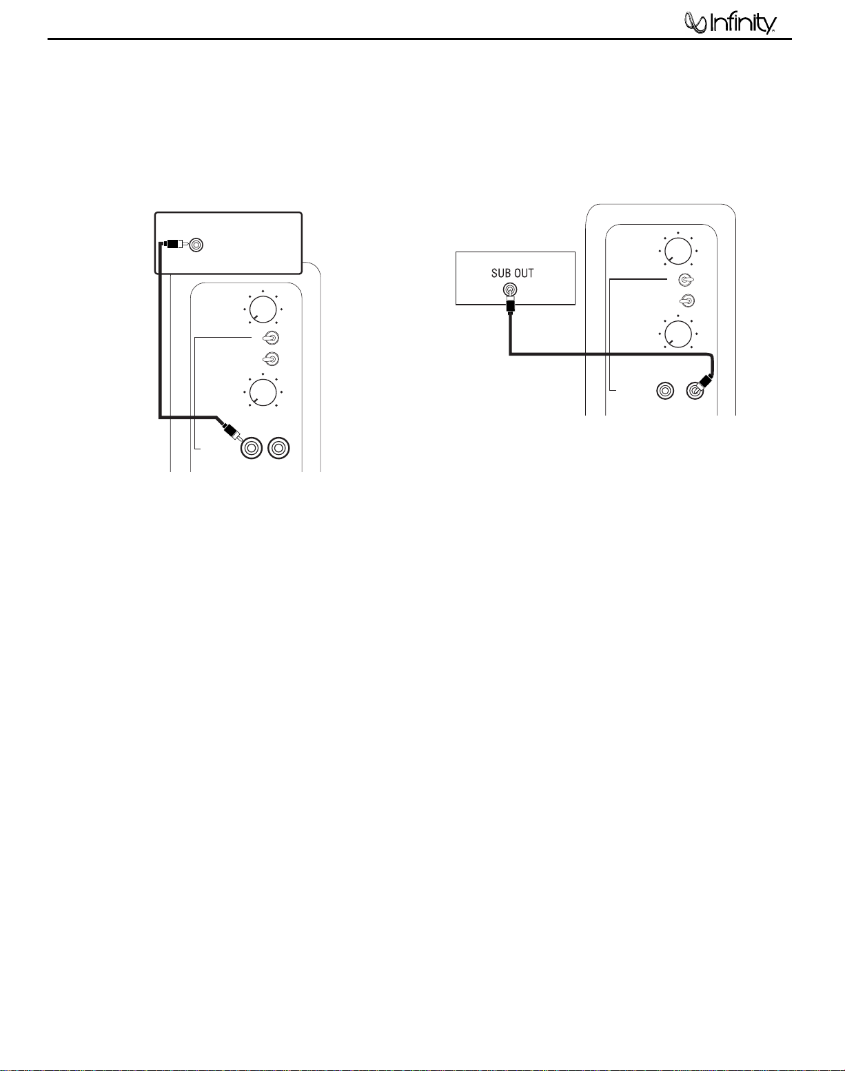
SUBWOOFER CONNECTIONS
If you have a Dolby* Digital or DTS®receiver/
processor with a low-frequency-effects (LFE)
or subwoofer output:
15'
subwoofer
cable
included
Set line-level/LFE switch to “LFE.”
If your receiver/processor does not contain
a Dolby Digital or DTS processor but has a
subwoofer output:
15' subwoofer
cable included
Set line-level/LFE switch to “Normal.”
NOTE:If your receiver/processor has only one sub out,
you may use either the L or R input.
TSS-1100
Page 7

TSS-1100
6
O
PERATION
Surround Modes
When using the system in a Dolby Digital or DTS home theater
system,make sure all speakers are set to “Small”.When using the
TSS-1100 in a Dolby Pro Logic* home theater system,make sure
the receiver’s center channel mode is set to “Normal.”
Some Dolby Digital-equipped receivers/processors offer different
setup options for each source or surround mode,e.g.,CD-stereo,
videotape,Dolby,Pro Logic.In each case,follow your equipment’s
instructions to ensure that the subwoofer output is turned on and
that the speakers are set to “Small”in each mode.
Power On
Plug your subwoofer’sAC cord into a wall outlet.Do not use the
outlets on the back of the receiver.
Initially set the Subwoofer Level Control
Turn on the subwoofer by pressing the Power Switch on the
rear panel.
Turn on your entire audio system and start a CD or movie sound-
track at a moderate level.
Auto On/Stand-By
With the Power Switch in the ON position,the LED on the front
panel will remain lit in red or green to indicate the On/Stand-By
mode of the subwoofer.
RED = STAND-BY (No signal detected,Amp Off)
GREEN = ON (Signal detected,Amp On)
The subwoofer will automatically enter the Stand-By mode after
approximately 10 minutes when no signal is detected from your
system. The subwoofer will then power ON instantly when a signal
is detected.During periods of normal use,the Power Switch
can be left on.You may turn off the Power Switch for extended
periods of nonoperation,e.g., when you are away on vacation.
Adjust Level
Turn the Subwoofer Level Control up about half way.If no
sound emanates from the subwoofer,check the AC-line cord and
input cables.Are the connectors on the cables making proper
contact? Is the AC plug connected to a “live”receptacle? Has the
Power Switch
have confirmed that the subwoofer is active,proceed by playing a
CD or DVD.Use a selection that has ample bass information.
Set the overall volume control of the receiver/processor to a
comfortable level.Adjust the Subwoofer Level Control
you obtain a pleasing blend of bass.Bass response should
not overpower the room but rather be adjusted so there is
a harmonious blend across the entire musical range.Many
users have a tendency to set the subwoofer volume too loud,
adhering to the belief that a subwoofer is there to produce lots of
bass.This is not entirely true.A subwoofer is there to enhance
bass,extending the response of the entire system so the bass
can be felt as well as heard.However,overall balance must
be maintained or the music will not sound natural.An experienced
listener will set the volume of the subwoofer so its impact on
bass response is always there but never obtrusive.
been pressed to the “On”position? Once you
to the“MIN”position.
until
Crossover Adjustment
The Crossover Frequency Control determines the highest
frequency at which the subwoofer reproduces sounds.For the
TSS-1100,it is recommended that this control be set at 120Hz
(approximately the 3 o’clock position).
NOTE:This control will have no effect if the LFE/Normal Switch
is set to LFE.If you have a Dolby Digital or DTS receiver/
processor,the Low-Pass Frequency is set by the receiver/
processor.Set the LFE/Normal Switch
LFE.Consult your owner’s manual to learn how to view or change
this setting.A setting of 120Hz – 150Hz is recommended.
on the subwoofer to
Phase Control
The Phase Switch determines whether the subwoofer
speaker’s piston-like action moves in and out with the main
speakers,0˚,or opposite the main speakers,180˚. Proper phase
adjustment depends on several variables such as room size,
subwoofer placement and listener position.Adjust the phase
switch to maximize bass output at the listening position.
Final Positioning
After correctly connecting the TSS-1100 system and verifying
that both the subwoofer and all satellite speakers are playing,it
is time to optimize the system for your particular listening room.
Earlier,you placed the subwoofer in its general location.Finding
the exact location for optimum performance sometimes only
involves moving the speakers up to a few inches in any
direction.We urge you,therefore,to experiment with placement,
if possible,until your speakers deliver their full potential.
M
AINTENANCE ANDSERVICE
The satellite and subwoofer enclosures may be cleaned using a
soft cloth to remove fingerprints or to wipe off dust.
All wiring connections should be inspected and cleaned or
remade periodically. The frequency of maintenance depends on
the metals involved in the connections,atmospheric conditions,
and other factors,but once per year is the minimum.
If a problem occurs,make sure that all connections are properly
made and clean.If a problem exists in one loudspeaker,reverse
the connection wires to the left and right system.If the problem
remains in the same speaker,then the fault is with the loudspeaker.If the problem appears in the opposite speaker, the
cause is in another component or cable.In the event that your
TSS-1100 ever needs service,contact your local Infinity dealer
or Infinity directly at 516.674.4INF (USA only) or
www.infinitysystems.com for a service center near you.
Page 8

TSS-1100
SERVICE NOTE
Access to woofer:
1) Carefully pry metal grille out of its recess with a sharp pointed
instrument such as an awl or dental pick – USE CAUTION and
protect the surface of the subwoofer from scratches or dents from
the work tool. Work evenly around the perimeter until the grill w/
gasket can be removed.
2) Remove the (6) Phillips screws holding the trim ring to the cabinet.
3) Remove the (6) Phillips screws holding the woofer to the cabinet.
REPLACEMENT: Assure when the woofer is replaced, it is exactly centered
in the counterbore.
7
Page 9

TSS-1100
TSS-1100 Satellites/Center & Packing
PART # DESCRIPTION
TSS-1100 system
1100-SATBPLT Complete TSS-1000 Satellite (Platinum)
1100-SATBCHR Complete TSS-1000 Satellite (Charcoal)
1100-CENBPLT Complete TSS-1000 Center channel (Platinum)
1100-CENBCHR Complete TSS-1000 Center channel (Charcoal)
1100-GSPLT Grill cover w / logo for satellite TSS-1100 platinum
1100-GCPLT Grill cover w / logo for center TSS-1100 platinum
1100-GSCHR Grill cover w / logo for satellite TSS-1100 charcoal
1100-GCCHR Grill cover w / logo for center TSS-1100 charcoal
1100-CRPLT Cradle for center TSS-1100 platinum
1100-CRCHR Cradle for center TSS-1100 charcoal
1100CTN-PLT Carton for TSS-1100 platinum 120V
1100CN-PLT230 Carton for TSS-1100 platinum 230V
1100CTN-CHR Carton for TSS-1100 charcoal 120V
1100CN-CHR230 Carton for TSS-1100 charcoal 230V
1100SOM-120 120V Owner manual for TSS-1100
1100SOM-230 230V Owner manual for TSS-1100
1100WS-120 TSS-1100 warranty sheet 120V
1100-SCTF1 Top styrofoam sat/center pack
1100-SCBF2 Bottom styrofoam sat/center pack
1100-WFT1 Top styrofoam subwoofer
1100-WFB2 Bottom styrofoam subwoofer
1100-BRTPLT TSS-1100 wall mount bracket Platinum
TSS-1100 Sa telli t e single pack
TSS-SAT1100PLT Complete packed TSS-1000 Satellite (Platinum) w/ accessories
TSS-SAT1100CHR Complete packed TSS-1000 Satellite (Charcoal) w/ accessories
1100-BRTPLT TSS-1100 wall mount bracket Platinum
1100-BRTCHR TSS-1100 wall mount bracket Charcoal
1100CTNSP-PLT TSS-1100 Sat single pack beauty carton -PLT
1100CTNSP-CHR TSS-1100 Sat single pack master carton-CHR
1100SATOM TSS-1100 Sat OM
8
Page 10

TSS-1100
9
TSS1100 su b Te st S et Up an d Pr o ce dur e
SYSTEM AURAL SWEEP TEST
Equipment needed:
• Function/signal generator/sweep generator
• Multimeter
• RCA cables
General Unit Function (UUT = Unit Under Test)
Switches/knobs on the amplifier faceplate:
Crossover Frequency Adjust full CW (150Hz)
Phase switch – either position
Normal/LFE switch - Normal
1. From the signal generator, Connect both right and left line level inputs (RCA jacks) – to signal generator and
UUT. Use Y-cable if necessary from mono source.
2. On the amplifier, turn the LEVEL control full Counterclockwise (Min).
3. Turn on generator, adjust to 150mV, 50 Hz.
4. Plug in UUT; turn the power switch ON. Turn LEVEL control full Clockwise (Max).
5. LED (on front panel) should now be Green; immediate bass response should be heard and felt from rear port
tube opening.
Sweep Function
1. Follow steps 1-5 above, using a sweep generator as a signal source.
2. Sweep generator from 20Hz to 1kHz. Listen to the cabinet and drivers for any rattles, clicks, buzzes or
any other noises. If any unusual noises are heard, remove woofer and test.
Driver Function (Woofer)
1. Remove woofer from cabinet (follow steps on exploded view page); detach + and - wire clips.
2. Check DC resistance of woofer; it should be 3.3 ohms±10%.
3. Connect a pair of speaker cables to driver terminals. Cables should be connected to an integrated
amplifier fed by a signal generator. Turn on generator and adjust so that speaker level output is 5.0V.
4. Sweep generator from 20Hz to 1kHz. Listen to driver for any rubbing, buzzing, or other unusual noises.
Page 11

TSS-1100
10
Page 12

y
TSS-1100
11
TSS-1100 120V ELECTRICAL PARTS LIST
Part Number Qt
MAIN PCB
Resistors
020-000098-400 4 Carbon film resistor 0R 1/8W C22-C24,31
020-220497-120 1 Carbon film resistor 2K2 1/4W J R11
021-100401-120 1 MOF Resistor 1K 1W J Kink R103
021-220202-120 1 MOF Resistor 22R 2W(S) J MB R10
021-240405-020 4 MOF Resistor 2K4/5WS J 17x6 R6,9,R7A,R9A
022-500003-020 1 Resistor KNP 0R05 3WS J FK TYPE R104
024-100298-120 2 SMD Resistor 10R 1/8W J 0805 R81,82
024-100398-120 1 SMD Resistor 100R 1/8W J 0805 R62
024-100498-100 1 SMD Resistor 1K 1/8W F 0805 R110
024-100498-120 7 SMD Resistor 1K 1/8W J 0805 R79,83,92,95,96,105,65
024-100598-120 26 SMD Resistor 10K 1/8W J 0805
024-100598-120 3 SMD Resistor 10K 1/8W J 0805 R2-4
024-100698-120 2 SMD Resistor 100K 1/8W J 0805 R3,112
024-100898-120 1 SMD Resistor 10M 1/8W J 0805 R121
024-110498-120 1 SMD Resistor 1K1 1/8W J 0805 R2A
024-110598-100 1 SMD Resistor 11K 1/8W F 0805 R98
024-110698-100 1 SMD Resistor 110K 1/8W F 0805 R4A
024-133598-100 1 SMD Resistor 13K3 1/8W F 0805 R35A
024-137698-100 1 SMD Resistor 137K 1/8W F 0805 R32
024-160398-120 1 SMD Resistor 160R 1/8W J 0805 R6A
024-162598-100 1 SMD Resistor 16K2 1/8W F 0805 R39
024-178498-100 1 SMD Resistor 1K78 1/8W F 0805 R38
024-180598-100 1 SMD Resistor 18K 1/8W F 0805 R29
024-187698-100 1 SMD Resistor 187K 1/8W F 0805 R45
024-200498-120 1 SMD Resistor 2K 1/8W J 0805 R108
024-200598-120 1 SMD Resistor 20K 1/8W J 0805 R94
024-220398-120 1 SMD Resistor 220R 1/8W J 0805 R90
024-220498-121 4 SMD Resistor 2K2 1/8W J 0805 R1,87,61,68
024-220598-120 1 SMD Resistor 22K 1/8W J 0805 R118
024-220798-120 1 SMD Resistor 2M2 1/8W J 0805 R80
024-237598-120 1 SMD Resistor 23K7 1/8W F 0805 R48
024-270498-120 2 SMD Resistor 2K7 1/8W J 0805 R73,64
024-280498-100 2 SMD Resistor 2K8 1/8W F 0805 R51,53
024-300398-120 1 SMD Resistor 300R 1/8W J 0805 R55
024-300598-120 1 SMD Resistor 30K 1/8W J 0805 R56
024-330498-120 8 SMD Resistor 3K3 1/8W J 0805 R7,8,12-15,59,67
024-330598-120 2 SMD Resistor 33K 1/8W J 0805 R4,5
024-332498-100 2 SMD Resistor 3K32 1/8W F 0805 R26,27
024-390498-120 1 SMD Resistor 3K9 1/8W J 0805 R93
024-390598-120 1 SMD Resistor 39K 1/8W J 0805 R77
024-430498-120 1 SMD Resistor 4K3 1/8W J 0805 R78
024-453498-100 1 SMD Resistor 4K53 1/8W F 0805 R36
024-453598-100 1 SMD Resistor 45K3 1/8W F 0805 R30
024-470298-120 2 SMD Resistor 47R 1/8W J 0805 R101,102
024-470398-120 3 SMD Resistor 470R 1/8W J 0805 R76,99,100
024-470498-120 2 SMD Resistor 4K7 1/8W J 0805 R85,86
024-470598-120 4 SMD Resistor 47K 1/8W J 0805 R44,47,49,107
024-470698-120 1 SMD Resistor 470K 1/8W J 0805 R70
024-470798-120 1 SMD Resistor 4M7 1/8W J 0805 R60
024-510398-120 1 SMD Resistor 510R 1/8W J 0805 R57
024-560498-120 1 SMD Resistor 5K6 1/8W J 0805 R1
024-560598-120 1 SMD Resistor 56K 1/8W J 0805 R122
024-620398-100 2 SMD Resistor 620R 1/8W F 0805 R16,18
024-680398-120 1 SMD Resistor 680R 1/8W J 0805 R5A
024-680498-120 6 SMD Resistor 6K8 1/8W J 0805 R46,91,40-43
024-680598-120 6 SMD Resistor 68K 1/8W J 0805 R33,34A,31,50,52,66
024-820598-120 1 SMD Resistor 82K 1/8W J 0805 R69
025-010300-000 1 Thermister TSE-103 K L:50mm TH1
Description Reference Designator
R2,17,19,37,54,58,63,71,72,74,75,84,88,89,97,106,113117,111,123,124, 119,120
Page 13

Y
s
TSS-1100
12
MAIN PCB
026-200595-269 1 VR PN:RD163121R03D-20KBx2(EJ) FREQUENC
026-500495-252 1 VR 5KA PN:RK163111R52B-5KA (EJ) LEVEL VR1
Capacitors
031-100144-103A 1 SMD Capacitor 0u001/50V K 0805 X7R TAP C79
031-100184-100A 2 SMD Capacitor 0u01/250V K 0805 X7R TAP C3,7
031-100244-100A 7 SMD Ceramic capacitor 0u01/50V K 0805 X7R 66,67,5,10,33,45,51,
031-100343-100A 2 SMD Capacitor 100pF/50V J 0805 NPO TAP C36,58)
031-100344-100 4 SMD Capacitor 0u1/50V K 0805 X7R TAPIN C1-4
031-100344-100A 16 SMD Capacitor 0u1/50V K 0805 X7R TAPIN C11,42-44,46-49,52,54,55,60,63,71,74,77
031-220243-103 1 SMD Capacitor (PHYCOMP) 0u022/50V J 080 C40
031-220344-300A 3 SMD Capacitor 220pF/50V K 0805 NPO TAP C20,21,19
031-330444-300 1 SMD Capacitor 3300pF/50V K 0805 X7R TA C34
031-470244-102A 2 SMD Capacitor 0u047/50V K 0805 X7R TAP C62,59
031-470344-100A 1 SMD Capacitor 470pF/50V K 0805 X7R TAP C80
031-560243-100A 2 SMD Capacitor 56pF/50V J 0805 NPO TAPI C57,61
031-820343-101A 1 SMD Capacitor 820pF/50V J 0805 NPO TAP C56
032-100484-200 2 END Mylar capacitor 1uF/250V K P:15 C70,C70B
032-270393-300 1 Mylar capacitor (ESK) 0u27/63V J (R) P:5 C29
032-820244-200 1 Mylar capacitor 0u082/100V K (R) C30
033-470464-270 1 NPE Capacitor 1K 4u7/100V K1 C73
033-680464-270 1 NPE Capacitor 6u8/100V K10 C72
034-100525-300 1 Electrolytic capacitor 10uF/25V M (R)0511 P:5 C35
034-100625-300 1 Electrolytic capacitor 100uF/25V M (R)6 C64
034-220525-301 5 Electrolytic capacitor 22uF/25V M (R)5x11 P:5 C4,9,41,50,53
034-330515-000 1 Electrolytic capacitor 33uF/16V M (R)0511 P:5 C39
034-330525-300 1 Electrolytic capacitor 33uF/25V M (R)05 C1
034-330615-300 2 Electrolytic capacitor 330uF/16V M (R)0812 P:5 C12,78
034-330780-300 2 Electrolytic capacitor 85 SNAPIN 3300uF/80V C6,8
034-470415-301 1 Electrolytic capacitor 4u7/50V M (R)0511 P:5 T C2
034-470515-200 1 Electrolytic capacitor 47uF/16V M (R)0511 P:2. C37
034-470615-301 1 Electrolytic capacitor 470uF/16V M (R)0812 P:5 C65
035-100393-301 2 Mylar capacitor (ESK TYPE) 0u1/63 C28,2A
035-100443-300 2 Mylar capacitor (ESK TYPE) 1uF/63 C25,26
035-220393-300 1 PE Capacitor 0u22/63V J P:5 C27
035-470293-300 1 PE Capacitor 0u047/63V J P:5 C1A
038-100363-300 2 MPE capacitor P:5 0u1/100V J C68,69
039-100384-100 1 Safety capacitor (0u1/250V) PN:HQX0.1K27 CXAC1
VR2
Semiconductor
051-000600-100 2 Transistor NPN PN:MPSW06RLRA TO-92 T Q2,Q16
051-003100-000 1 Transistor NPN PN:TIP 31C TO-220 (MO Q4
051-005600-100 1 Transistor PNP PN:MPSW56RLRA TO-92 T Q3
051-222200-100 1 Transistor NPN (ON SEM) PN:MPS2222AR Q21
051-290700-100 2 Transistor PNP (ON) PN:MPS2907A RLRA Q19,23
051-540101-000 1 Transistor PNP(FAIRCHILD PN:2N5401 T Q1
051-555100-000 1 Transistor NPN PN:2N5551 TO-92 TAPIN Q17
051-640001-000 2 MOSFET N-Channel PN:IRF640N TO-2 Q18,22
052-400080-000 1 Bridge Rectifier PN:RS804 400V,8A BR1
053-211100-000 1 IC, IR2111 HALF-BRIDGE DRIVER U7
054-000100-100 5 SMD DIODE PN:ES1D 200V 1A D5,26,29,33,38
054-001002-100 1 SMD ZENER DIODE PN:BZX84C10 10V D35
054-001501-100 3 SMD ZENER DIODE PN:BZX84C15 15V D6,7,9
054-007200-100 2 SMD IC PN:TL072CDR SO-8 DUAL OP-AMP U1,5,6
054-007400-100 2 SMD IC PN:TL074CDR QUAD OP-AMP U2,3
054-008403-100 1 SMD ZENER DIODE BZX84C3V0 SOT-23 D25
054-011400-100 1 SMD Transistor PN:DTC114TKA SMT3 TAP Q7
054-033904-100 7 SMD Transistor PN:MMBT3904LT1 SOT23 Q11,14,13,5,8,25,9
054-033906-100 4 SMD Transistor PN:MMBT3906LT1 SOT23 Q6,10,12,15
054-045580-100 1 SMD IC NJM4558M-TE3 DUAL OP-AMP U4
054-050601-100 2 SMD ZENER DIODE PN:BZX84C5V6 5.6 D36,37
054-390402-100 1 SMD Transistor (SC00044) PN:MMBT3904TR Q1
054-414803-100 21 SMD DIODE PN:LL4148
054-414803-100 2 SMD DIODE PN:LL4148 D1,2
D1-4,8,27,30,31,34,39, 11,14,16,17, 20-22,18,19,28,32
Page 14

y
K
N
TSS-1100
13
MAIN PCB
054-540100-100 3 SMD Transistor (PNP) PN:MMBT5401 LT1 Q20,24,26
THERMAL SENSE PCB
024-100598-120 3 SMD Resistor 10K 1/8W J 0805 R138-R141
024-560498-120 1 SMD Resistor 5K6 1/8W J 0805 R140
031-100344-100 4 0U1/50V K 0805 X7R C81-82, C13,C38
054-007200-100 1 SMD IC TL072CDR SO-8 U8
054-390402-100 1 SMD Transistor MMBT3904TR Fairchild Q27
054-414803-100 2 SMD Diode LL4148 Vishay D44-45
Miscellaneous
1100-LED 1 LED ass'
042-010147-000 1 Transformer PN:YT-15250 (TSS1100/120V
043-300101-000 1 INDUCTOR PN:YT-10033 30uH L2
043-324300-000 1 INDUCTOR 324uH YT-10778 L4
043-560200-000 1 INDUCTOR 56uH YT-10779 L1
043-840100-000 1 Inductor PN:YT-14389 84uH TSS1100/23 L3
044-100100-000 2 SMD FERRITE BEAD PN:321611 600R/ FB1,FB2
061-020000-000 2 Knob ABS HTS-10/20 φ20x15m/m UL 94V-0 BLK
061-314002-000 2 Strain Relief P/N SB4F-2
061-400014-000 4 RUBBER FOOT ID:6.2 OD:11.5 t=2mm 55degree BLK
061-700044-000 3 Mica 13x18mm TO-220 holeless Q4,18,22
063-010012-000 4 Bracket for power transistor P/N:TRK-1 for ICx4
063-321102-000 1 PANEL (ARMANDO) 322x105.7x15mm A BS-94VO BL
063-531808-000 1 Bucket (PB-10/12) ABS 322x105.7x14 6.5mm BLK (94VO)
066-120300-900 5 CABLE TIE CV-120S
072-010007-000 1 RCA base SCJ-1020 2P(G) WHT,RED CONN1
073-011001-400 2 BRACKET 16x34mm t=0.8mm brass plated for PANEL
073-032315-601 1 Heatsink, black anodized 70x58x20mm, thread
073-050001-000 2 FUSE CLIP P/N:CFFH1206
074-020018-000 1 ROCKER SW (POWER) PN:RF1003-BB4-0
074-030002-000 2 TOGGLE SW PN:L101-T2B4QE SW5,SW6
074-300018-000 1 RELAY PN:943-1C-48D K1
083-041802-009 1 UL Power Cord SPT-2 BLK 6 feet
093-105202-300 1 FUSE:UL GSL(2AG) FUSE:2A,250V,5* F1
008-061215-000 1 GASKET C4305 12x15 t=5mm CR PSA for Thermister
008-062002-002 1 GASKET (PB10/12) PN:L-32 200x20m
008-062002-012 1 GASKET (PB10/12) 200x20mm t=2mm CR4305 PSA for Cover
008-062004-012 1 GASKET 200x35x3mm PSA for spkr cable
008-063208-000 6 GASKET C4305 321x8 t=1mm CR PSA for Cover
008-069304-000 6 GASKET C4305 93x4 t=1mm CR {SA for Cover
041-115001-000 1 BEAD COIL YT-10911 L5
230V VARIATIO
086-021818-030 1 VDE Power Cord LF2-75
093-205201-320 1 Fuse 1.25A/250V VBS UTE F1
042-010148-000 1 Power Transformer PT1
072-060170-000 4 Binding Post
072-060213-000 4 Binding Post Plug (Black)
072-060214-000 4 Binding Post Plug (Red)
Page 15

14
TSS-1100
Page 16

15
TSS-1100
Page 17

16
TSS-1100
Page 18

17
TSS-1100
THERMAL SENSE PCB
Page 19

TSS-1100
18
Page 20

TSS-1100
19
Page 21

TSS-1100
20
Page 22

TSS-1100
21
Circled area =THERMAL SENSE PCB
N/U = Not Used
Page 23

TSS-1100
22
Page 24

TSS-1100
23
 Loading...