

Page 1

INFINITY
Residential Elevator
Roped Hydraulic Residential Elevator
Planning Guide
ASME A17.1 - 2000 Part 5 Section 5.3
CAN/CSA B44 - 2000 Part 5 Section 5.3
Effective April 1, 2004
®
ELEVATORS and LIFTS
®
Page 2

INFINITY
Residential Elevator
Introduction
This planning guide is designed to assist architects, contractors, home owners and elevator professionals in
planning for an INFINITY Residential Elevator to meet the requirements of ASME A17.1 Part 5, Section 5.3
and CAN/CSA B44 Part 5, Section 5.3.
We strongly recommend that you contact the code authority having jurisdiction in the area(s) where the
elevator will be installed to become familiar with all the legal requirements governing the installation and use
of elevators in private residences. It is extremely important for you to know and adhere to all regulations
pertaining to the installation and use of elevators.
IMPORTANT NOTICE
This Planning Guide provides nominal dimensions and specifications useful for the initial planning of an
elevator project. Before beginning actual construction be sure to receive application drawings customized
with specifications and dimensions for your specific project.
Elevator configurations and dimensions are in accordance with our interpretation of the standards set forth by
ASME A17.1 Part 5, Section 5.3 and CAN/CSA B44 Part 5, Section 5.3. Please consult Concord Elevator Inc.
or the authorized Concord dealer in your area for more specific information pertaining to your project,
including any discrepancy between referenced standards and those of any local codes or laws.
The dimensions and specifications in this Planning Guide are subject to change (without notice) due to
product enhancements and continually evolving codes and product applications.
Planning for an INFINITY Residential Elevator
1. Determine customer’s intention for use.
2. Determine code requirements of site.
3. Determine installation parameters of site.
4. Use Page 4 and 5 to determine the car type and hoistway size requirements.
5. Use pages 5 to 8 to plan for machine room and electrical requirements.
Contents
Equipment for residential elevator Page 3
Hoistway requirements Page 4 - 5
Overhead clearance requirements Page 5
Hydraulic drive machine room layout Page 5
Specifications Page 6 - 8
Rail reactions Page 8
Recommended hoistway construction Page 9 - 12
CPG-INFVER01 © 2004, Concord Elevator Inc.
Page 2 of 12
Page 3

Equipment for Residential Elevator
This elevator meets the requirements of
ASME A17.1 Part 5, Section 5.3 and CAN/CSA B44 Part 5, Section 5.3
for a Residential Elevator
INFINITY
Residential Elevator
General
Rated Load: 750 lbs. (340kg) or 1000 lbs. (454kg)
Nominal Speed: 36 fpm (.18 ms)
2 Stop up to 10' travel (Up to 50' optional)
Data Plates, capacity tags and rope tags
Minimum pit depth: 8" (203mm)
Minimum overhead clearance: 92" (2337 mm)
Presentation drawings
Mechanical Equipment
208/230V, 60 Hz, 30 Amp single phase power supply
8 lb. T-Rail system
Two 3/8" diameter wire rope cables
Sling assembly
Forged rope sockets
Roped Hydraulic Drive
1:2 roped hydraulic single stage cylinder
3 hp submersed motor with two speed valve
assembly
Standard Cab and Appointments
Cab Size: 35" (914 mm)W x 48" (1219 mm)L
x 80" (2032 mm)H (inside clear measurements)
Cab Walls: ½" (13 mm) Melamine or M.D.F. panels
with black anodized aluminum trim
Cab Ceiling: Architectural white steel ceiling with four
(4) recessed incandescent down lights
Solid oak handrail painted black
Stainless steel flush mounted cab operating panel
Digital floor and directional indicator
Illuminated cab operating buttons
Recessed plywood flooring
Telephone jack
(optional on SRE)
Controls
Solid state (Plug n' Play) controller
Fully automatic operation
Constant pressure operation available
Stainless steel rectangular hall call stations
Automatic cab lighting with battery back-up operation
Emergency alarm and stop button
Floor specific battery lowering
Magnetic tape reader for floor selection and levelling
Automatic home landing to pre-selected floor
Safety Devices
Easy access emergency manual lowering
Upper and lower terminal limits
Manual reset slack rope safety switch
Automatic bi-directional leveling
Anti creep device
Pit switch
Pump run timer
Car top stop switch
Emergency battery back-up for lighting, alarm and
lowering
Cab gate safety switch
Other Options - All Models
Automatic cab gate operator
Automatic operators for hoistway doors
Various styles of interlocks for hoistway doors
90 degree entry/exit cab
2 Exit openings at one landing
35" x 54" or 35" x 60" cab sizes
96" (2743 mm) high cab
3 or 4 stops with up to 50 ft. (15.24 m) of travel
Finished oak hardwood flooring
Two piece hydraulic jack for lifting heights exceeding
32 ft. (9.75 m)
Other Options – Infinity Luxury Model
Recessed telephone cabinet in stainless steel or
brass
Various panel-fold cab gates or black scissor gate
Custom cab sizes up to 15 sq.ft. (1.39 sq. m)
Solid cherry, maple or oak raised panel walls and
ceiling
Thermofoil red apple, honey apple, pine or white ash
raised panel walls and ceiling
Unfinished oak veneer walls and ceiling
Brass or Designer cab operating panel
Brass rectangular or oval hall/call stations
Stainless steel oval hall/call stations
Unfinished or finished oak handrail
Cylindrical brass or stainless steel handrails
Recessed brass down lights
Clear or brass anodized cab trim
5 stops – requires PLC Controller Package
CPG-INFVER01 © 2004, Concord Elevator Inc.
Page 3 of 12
Page 4
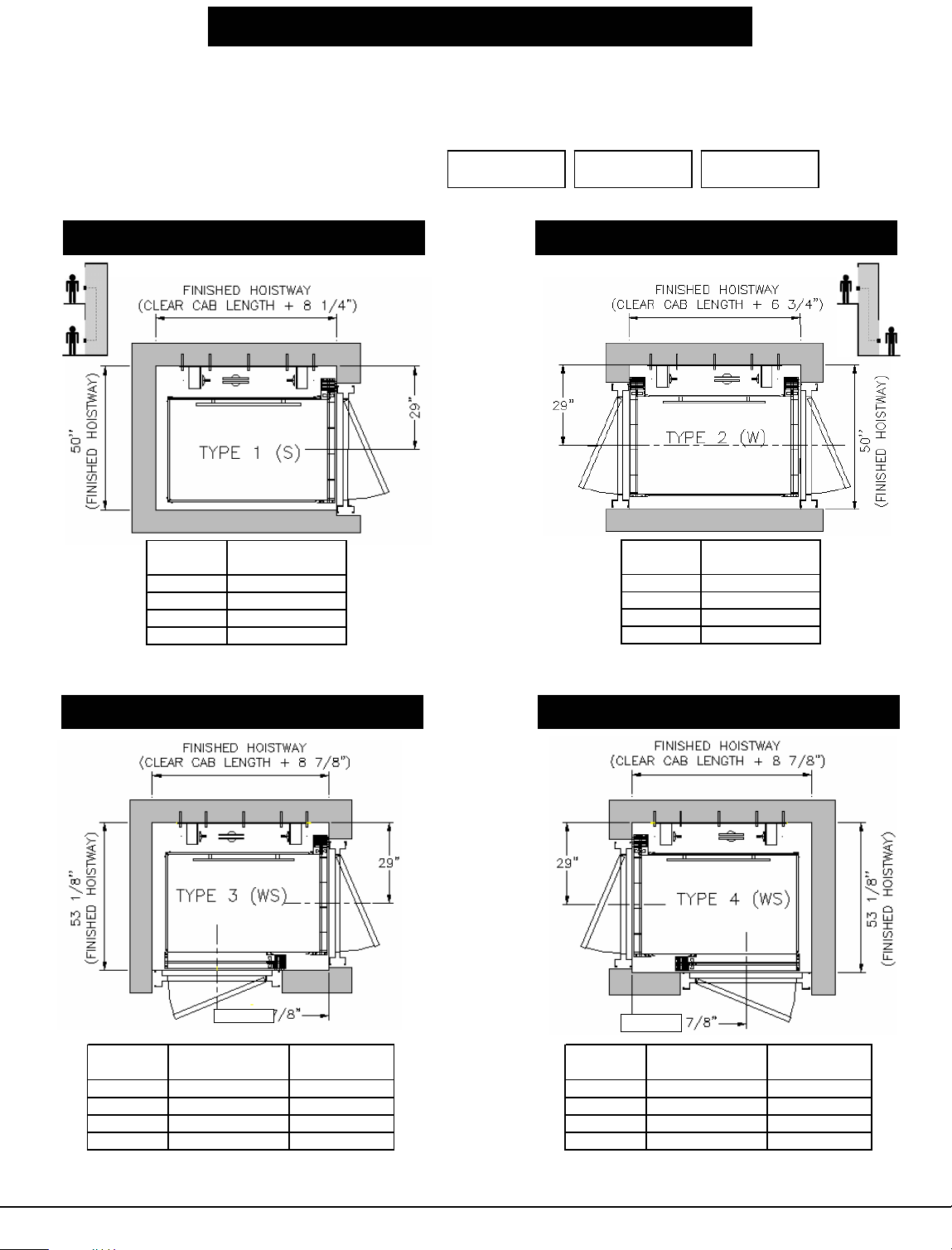
Hoistway and Cab Configurations
g
g
g
g
INFINITY
Residential Elevator
Choice of Five Variations
Important Note: Finished hoistway dimensions must include the drywall. Determine the fire
rating of the hoistway, the type and layers of sheet rock and build only off shop drawings
specific to your project.
Available Cab Dimensions (Clear Inside):
35" x 48" 35" x 54" 35" x 60"
Type 1 (S) - Enter/Exit Same Side
LENGTH
WIDTH
Clear Cab
th
Len
48" 56 1/4"
54" 62 1/4"
60" 68 1/4"
X X + 8 1/4"
Finished
Hoistway Length
Type 3 (WS) - 90oEnter/Exit
Type 2 (W) - Enter/Exit Opposite Side
LENGTH
Clear Cab
Len
th
48" 54 3/4"
54" 60 3/4"
60" 66 3/4"
X X + 6 3/4"
Finished
Hoistway Length
Type 4 (WS) - 90oEnter/Exit
WIDTH
LENGTH
WIDTH
see chart
Clear Cab
Len
th
48" 56 7/8" 33 7/8"
54" 62 7/8" 39 7/8"
60" 68 7/8" 45 7/8"
X X + 8 7/8" X + 14 1/8"
Finished
Hoistway Length
Side Entrance
Center Lines
Clear Cab
see chart
Len
th
48" 56 7/8" 33 7/8"
54" 62 7/8" 39 7/8"
60" 68 7/8" 45 7/8"
X X + 8 7/8" X + 14 1/8"
LENGTH
Finished
Hoistway Length
CPG-INFVER01 © 2004, Concord Elevator Inc.
WIDTH
Side Entrance
Center Lines
Page 4 of 12
Page 5

Hoistway and Cab Configurations
g
INFINITY
Residential Elevator
Type 5 (S) - Enter/Exit Same Side
(Opposite Sling)
LENGTH
see chart
Clear Cab
th
Len
48" 54 1/4" 27 1/8"
54" 60 1/4" 30 1/8"
60" 66 1/4" 33 1/8"
X X + 6 1/2" (X + 6 1/4") / 2
Finished
Hoistway Length
Side Entrance
Center Lines
WIDTH
Diagram of Elevator Shaft
Overhead
Elevator
Guide
Rails
Hydraulic
Lifting
Cylinder
3/8" Wire
Rope
Cable
Elevator
Cab
Cab
Operating
Panel
Cab Gate
Pit
Hoistway Overhead Clearance
Infinity Cab Height Overhead Clearance Requirements
80" Cab Height 92" Minimum Clear Overhead
96" Cab Height 108" Minimum Clear Overhead
Typical Hydraulic Drive Machine Room Layout
Machine Room Plan at Lower Level
Machine room must be built in accordance with
local, state/provincial and national codes.
Machine room lighting shall be a minimum of 19
foot candles at working surfaces. The switch for
the light must be within 18" of the strike side of the
machine room door. The switch, light and wiring
are provided and installed by others. A
convenience outlet, 115 VAC 15 AMP single
phase with G.F.I. shall be located next to the light
switch in the machine room. provided and installed
by others. NEC requires a 30" wide x 36" deep
work space in front of the disconnects and the
elevator controller.
A telephone line circuit is to be provided and
installed by others. This circuit must be connected
to an outside line.
Controller/Pump Unit Dimensions = 30"W x 16"D x 55"H
CPG-INFVER01 © 2004, Concord Elevator Inc.
Page 5 of 12
Page 6

Specifications for Part 5.3 Compliance
INFINITY
Residential Elevator
PART 1 - GENERAL
SCOPE
To furnish all labor, materials and equipment necessary or required to
fully complete the installation of the elevator as indicated on the
Drawings and Specifications. This suggested specification is intended to
cover the complete installation of the Concord INFINITY Residential
Elevator design.
SYSTEM DESCRIPTION
The elevator assembly shall consist of a power unit, car, guide system,
1:2 cable hydraulic lifting device, control system, signals and alarms,
electrical wiring, and parts and accessories necessary to provide
required performance, operation, code and safety requirements.
QUALITY ASSURANCE
1.3.1
The elevator shall meet or exceed the applicable regulations of all
governing agencies and be in conformance with the applicable sections
of the most current edition of the following codes and standards:
a) ASME A17.1 "Safety Code for Elevators and Escalators;
"Private Residence Elevators". CAN/CSA B44 P art 5 S ectio n 5. 3
b) ICC/ANSI A117.1-1998 "Accessible and Usable Buildings and
Facilities".
c) NFPA 70-1999 "The National Electric Code" (NEC).
d) ADAAG "Americans With Disabilities Act Accessibility
Guidelines" (where applicable).
e) CSA B44.1/ASME A17.5 "Elevator and Escalator Electrical
Equipment"
f) Local codes and regulations, as applicable.
PART 2- PREPARATORY WORK BY OTHERS
2.1
The following preparatory work to accommodate/receive the elevator is to
be done by others.
2.1.1
Provide power unit machine room to meet applicable Codes and
Standards.
2.1.2
Permanent power (220 Volt, Single Phase, 30 Amp or 208 Volt, 3 Phase,
30 Amp.) to operate the elevator to b e pr ovide d t o a L ockable
Fused/Cartridge Type Disconnect Switch with auxiliary contact/switch for
emergency battery lowering. Refer to architectural drawings for
permanent power specifications and location of disconnects.
2.1.3
Provide 110-volt lighting supply and disconnect. Refer to architectural
drawings for permanent power specifications and location of disconnects.
2.1.4
Provide an enclosed, plumb and square hoistway with smooth interior
surfaces. Include for fascias or furring of hoistway interior where
applicable.
2.1.5
Provide doors, frames, and door hardware.
Provide rough openings as per elevator contractor’s drawings.
2.1.6
Provide substantial, level pit floor slab to support loads indicated on
elevator contractor’s shop drawings.
1.3.2 REQUIREMENTS OF THE REGULATORY AGENCIES
a) Fabricate and install work in compliance with all applicable
jurisdictional authorities.
b) File shop drawings and submissions to local authorities as the
information is made available. Company pre-inspection and
jurisdictional authority inspections and permits are to be made
on a timely basis as required. Work will include all inspections
and re-inspections that are required to ensure licenses are
issued.
1.3.3 SUBCONTRACTOR QUALIFICATIONS
a) Execute work of this specification only by a contractor/company
who has adequate product and public liability insurance in
excess of one million dollars.
b) Skilled tradesmen must be employees of the contractor and
perform the work on a timely basis. Employees must be trained
by the manufacturer and be supervised by the elevator
contractor.
1.3.4 SUBSTITUTIONS
No substitutions will be considered unless written request for approval
has been submitted by the bidder and received by the architect at least
10 days before the receipt of bids. Each such request shall include a
complete description of the proposed substitute including drawings, test
data, photographs, and any other information needed for consideration.
2.1.7
Provide adequate support for guide rail fastenings.
2.1.8
Provide pit water proofing to maintain a dry pit. S u mp p ump wh ere
required by authority having jurisdiction. (see elevator contractor for
location).
2.1.9
Provide 8" (203 mm) minimum pit.
2.1.10
Provide 92" (2337 mm) minimum overhead (distance from floor at upper
level to underside of roof).
PART 3 – SUBMITTALS
3.1 SHOP DRAWINGS (presentation)
The shop drawings shall show a complete layout of the elevator
equipment detailing dimensions, clearances and location of machinery.
Including the following:
a) Drawings show the dimensions including plans,
elevations, and sections to show equipment locations.
b) Load and reaction drawings shall be provided by the elevator
manufacturer and detailed on drawings.
CPG-INFVER01 © 2004, Concord Elevator Inc.
Page 6 of 12
Page 7

Continued
Specifications for Part 5.3 Compliance
INFINITY
Residential Elevator
PART 4 – PRODUCT DATA
4.1 MANUFACTURER/PRODUCT
The elevator shall be the CONCORD INFINITY Residential Elevator
manufactured by Concord Elevator Inc. Toll Free (800) 661-5112 and
(905) 791-5555, Fax (905) 791-2222
Dealer Name ___________________________________
Number _______________________________________
Rated Load: 750 lbs. (340 kg.)
Nominal Speed: 36-fpm (0.18 m/s)
Car Dimensions: 36" W x 48" D (914 mm W x 1220 mm D)
Operation: Automatic
Gate Type: Horizontally collapsible, accordion style with 3 vision panels
Power Supply: 220 Volt, Single Phase, 30 Amps or 208 Volt, 3 Phase,
30 Amps
Travel Distance: 50 ft. (15.2 m) max __________________
Levels Served: (up to 5, max. 4 - SRE) ________________________
Number of Openings: Two (2) Maximum
Lighting Supply: 110 Volt, 1 Phase, 60 Cycle, 15 Amps
Jack Type: 1:2 Cable Hydraulic
Pump Type: Submersible with Variable Speed Valve Levelling
Device Type: Magnetic
4.2 CAR ENCLOSURE
4.2.1 WALLS
1/2" (13 mm) Melamine panels and black anodized aluminum trim.
4.2.2 CEILINGS
Architectural white with four (4) recessed incandescent down lights.
4.2.10 AUTOMATIC LIGHTS
Overhead lights in the car compartment shall turn ON automatically when
the elevator door is opened and will stay on while the elevator is in use.
The elevator lights will shut off by a timer when the elevator is not in use.
4.3 DOOR LOCKS
Locks shall be electrically operated and electrically released at floor level
and will remain unlocked until hall or car call is placed. When released,
the locks’ lag member will drop down and close the electrical circuitry to
ensure the elevator cannot move unless the door is closed and locked (a
true interlock).
4.4 HALL CALL STATIONS
Provide a keyless hall call station with an illuminated call button and
stainless steel cover plate for each landing.
4.5 PLATFORM TOE GUARD
A platform toe guard shall be provided at each car entrance opening to
extend below the car entrance opening for safety.
4.6 LEVELING DEVICE
a) The elevator shall be provided with a 2-way leveling device, which
will maintain the car within 1/2" (13mm) of the landing.
b) Levelling device sensors shall be located in a position to
be inaccessible to unauthorized persons.
4.7 CAR GATE REQUIRED OPT I ON
Horizontally collapsible accordion style woodfold car gate with rattan
panels and three (3) clear acrylic vision panels car gate shall enclose
each car entrance.
4.2.3 FLOOR
Plywood sub-flooring.
4.2.4 HANDRAIL
Black painted oak handrail located on control panel.
4.2.5 EMERGENCY OPERATION
The elevator car shall be equipped with a battery-powered emergency
lowering device and alarm that can be actuated on the failure of normal
building power supply. Battery will be rechargeable type with an
automatic recharging system.
4.2.6 EMERGENCY LIGHT
The car shall be equipped with an integral emergency light that will
illuminate automatically in the event of a main power failure.
4.2.7 CAR OPERATING PANEL
Car operating panel shall consist of metal push buttons with halo
lighting for each landing, an emergency stop button, an alarm button
and a key switch. The key is removable in both the on and off position.
All mounted on a #4 finished stainless steel panel. Car station panel is
hinged.
4.2.8 DIGITAL FLOOR INDICATOR
Digital floor indicator located in the control panel will display the
location and direction of travel (floor number) of the elevator in the
shaft. (optional on SRE model)
4.2.9 CAR LIGHTING
The car lighting shall consist of four (4) low voltage recessed
incandescent down lights. The failure of one lamp shall not cause the
remaining lamp to extinguish.
4.8 HYDRAULIC POWER UNIT
a) The pump and motor shall be the submersible type installed
inside the oil tank.
b) The controller shall be integrally mounted on the power unit
frame and pre-wired and tested before shipment.
c) Control circuitry to be located at the top of the oil tank.
d) The power unit control valve shall be a variable speed
proportional valve type that includes all hydraulic control valving
inherently.
This valve shall incorporate the following features:
(i) Up and down acceleration and deceleration speed adjustment for
smooth starts and stops.
(ii) Smooth stops at each landing shall be an inherent feature of the
valve.
(iii) Adjustable pressure relief valve.
(iv) Manually operating 'DOWN' valve to lower elevator in an
emergency.
(v) Pressure gauge indicating in P.S.I. and Bars.
(vi) Gate valve to isolate cylinder from pump unit.
(vii) Negative pressure switch.
4.9 CYLINDER AND PLUNGER
4.9.1
The cylinder shall be constructed of steel pipe of a sufficient thickness
and suitable safety margin. The top of the cylinder shall be equipped with
a cylinder head with an internal guide ring and self-adjusting packing.
4.9.2
The plunger shall be constructed of a steel shaft of a proper diameter
machined true and smooth. The plunger shall be provided with a stop
electrically welded to the bottom to prevent the plunger from leaving the
cylinder.
CPG-INFVER01 © 2004, Concord Elevator Inc.
Page 7 of 12
Page 8

Continued
Specifications for Part 5.3 Compliance
INFINITY
Residential Elevator
4.10 CABLE
Minimum of two 3/8" (10 mm) IWRC Galvanized Aircraft Cables.
Minimum breaking strength of 14,400 lbs. each.
4.11 SAFETY DEVICE
A "slack/broken cable" safety device shall be supplied which will stop
and sustain the elevator and its rated load, if either of the hoisting cables
become slack or breaks. The safety device shall be resettable by the
operation of the elevator in the up ward directio n . A switch shall be
mounted in such a position as to sense the operation of the safety
device, and will open the safety circuit to the controller to prevent
operation of the elevator in either directio n.
4.12 GUIDE YOKE
The 1:2 guide yoke/sheave arrangement shall be supplied with a
sheave, guide shoes, roller bearings and adjustable cable guards. The
sheave shall be finished with rounded grooves to fit the cables.
4.14 FINAL LIMIT SWITCH
The elevator shall be equipped with a final limit switch to cut off all power
to the elevator if the upper normal terminal stopping devices fail.
4.15 GUIDE RAILS AND BRACKETS
4.15.1
Steel 8lb/ft "T" guide rails and brackets shall be securely fastened to the
building structure.
4.15.2
Brackets shall securely hold the guides in a plumb and true position
regardless of car loading.
4.15.3
Guides shall be bolted through the hoistway enclosure with back-up
plates, washers and nuts. Subject to architects’ alterations and approval.
4.16 CAR SLING
4.16.1
Car sling shall be fabricated from steel members with adequate bracing to
support the platform and cab.
4.16.2
The buffer-striking member on the underside of the car must stop the
elevator before the jack plunger reaches its down limit of travel.
4.16.3
Guide shoes to be solid slipper type with polyurethane inserts.
4.17 WIRING
All wiring and electrical connections shall comply with applicable codes,
insulated wiring shall have flame retardant and moisture proof outer
covering and shall be run in conduit or electrical wireways. Traveling
cables shall be flexible and suitably suspended to relieve strain.
Part 5 - EXECUTION
5.1 EXAMINATION
All site dimensions shall be taken to ensure that tolerances and
clearances have been maintained and meet local regulations.
5.2 PREPARATION
Pre-inspect the construction and service requirements for "Work by
Others". These requirements will be included in drawings, diagrams,
engineering data sheets and special instructions before the work
commences.
Rail Orientation to Support Wall
Typical Lower Rail Bracket Configuration
Rail Reactions
R1 = 304 LBF
R2 = 194 LBF
Rail reactions do not include safety factors.
Applicable safety factors must be considered
in hoistway design.
CPG-INFVER01 © 2004, Concord Elevator Inc.
Page 8 of 12
Page 9

Wood Hoistway Construction
Suggested Support Wall
Wood Construction
Note:
The drawings on this page
are for reference only.
Building structural engineer
to ensure that the building
and hoistway will support
all loads imposed by the lift
equipment.
Fire rating of hoistway is
subject to local building
codes.
INFINITY
Residential Elevator
CPG-INFVER01 © 2004, Concord Elevator Inc.
Page 9 of 12
Page 10

Wood Construction Sectional View
INFINITY
Residential Elevator
Wood Construction Plan View Rail Bracket
CPG-INFVER01 © 2004, Concord Elevator Inc.
Page 10 of 12
Page 11

Masonry Construction Elevation View
BLOCK WALL
(8" MINIMUM)
INFINITY
Residential Elevator
(See Note 1)
Masonry Construction Plan View Rail Bracket
Note: For 8" Block
Use Thru Bolts
CPG-INFVER01 © 2004, Concord Elevator Inc.
Page 11 of 12
Page 12

Elevator Rail Support Wall
Drawing Notes
1 See Elevator Drawing for rail bracket spacing and pit depth.
2 Wall lateral support spacing:
- for 2" x 4" studs, use 6' -10" (2090 mm) max.
- for 2" x 6" studs, use 13' -6" (4120 mm) max.
3 Sheathing installation: install sheets vertically full width of shaft or min.
centred on rail brackets.
4 Connectors to resist horizontal load but allow vertical movement.
For Wood, use 2" x ¼" cap screw lag bolts.
General Specifications
G1 The design and construction of all work is to conform to the local applicable building code.
G2 Read these drawings in conjunction with all related architectural, mechanical, electrical, and
elevator drawings as well as any other contract documents.
G3 The wall drawings have been prepared using engineering principles and the design loads that are
applied by the elevator rails to the wall. However, the details and member sizes and the
attachments to the structure should not be construed as a complete design of the wall system.
The contractor and/or the project engineer is responsible to evaluate the other loads that are
applied to the wall from the floor or roof system and modify member sizes or connections as
required by their analysis.
G4 Do not scale the drawings.
G5 See elevator shop drawings for service loads (including dynamic effects)
which are: - horizontal load parallel to the wall = 194 lb.
- horizontal load perpendicular to the wall = 304 lb.
G6 Wood SPF NO 1/2 Mix
Concrete 3000 psi (20 Mpa) @ 28 days. If exposed use 5% to 7% air content.
A. Bolts ASTM A307
Mortar Type “S”
Masonry
Grout 2100 psi (14 Mpa) High Slump
Block 2100 psi (14 Mpa) on net area
G7 Wall to be installed plumb and square within 1/8" (3mm) of top and bottom of shaft.
G8 Wall lateral support spacing (H) selected for maximum horizontal deflection of H/360 from rail
loads.
INFINITY
Residential Elevator
Wood Construction
W1 Separate wood from concrete with waterproof barrier or use pressure treated wood.
W2 Bridging Maximum Spacing: Load Bearing or Shear walls – 4' c/c
W3 Nail or screw sheathing at 6" c/c at edges and 12" c/c to other members.
Use 2.5" Standard Ardox nails or 2" #12 Screws.
Masonry Construction
M1 All masonry construction to conform to applicable local standards
M2 Reinforce lintel blocks with 2-15m bottom bars unless noted.
M3 Provide continuous ladder type joint reinforcement at 16" (400) c/c.
www.concordelevator.com
1-800-661-5112
ELEVATORS and LIFTS
CPG-INFVER01 © 2004, Concord Elevator Inc.
Page 12 of 12
®
 Loading...