

Page 1

Foreword
Your INFINITI represents a new way of
thinking about vehicle design. It integrates advanced engineering and superior craftsmanship with a simple, refined
aesthetic sensitivity associated with traditional Japanese culture.
The result is a different notion of luxury
and beauty. The car itself is important,
but also is the sense of harmony that the
vehicle evokes in its driver, and the
sense of satisfaction you feel with the
INFINITI — from the way it looks and
drives to the high level of dealer service.
To ensure that you enjoy your INFINITI to
the fullest, we encourage you to read this
Owner’s Manual immediately. It explains
all of the features, controls and performance characteristics of your INFINITI; it
also provides important instructions and
safety information.
A separate Warranty Information Booklet
is included in your Owner’s literature
portfolio. Always carry it with you when
you take your vehicle to an INFINITI
dealer. The Warranty Information
Booklet contents provide complete information about all warranties covering this
vehicle, the requirements to keep the
warranties in effect as well as the
INFINITI Roadside Assistance program.
Additionally, a separate Customer Care
and Lemon Law Information Booklet will
explain how to resolve any concerns you
may have with your vehicle, as well as
clarify your rights under your state’s
lemon law.
INFINITI is dedicated to providing a satisfying ownership experience for as long
as you own your car. Should you have
any questions regarding your INFINITI or
your INFINITI dealer, please contact our
Consumer Affairs department at:
In U.S. 1-800-662-6200.
In Canada 1-800-361-4792.
READ FIRST — THEN DRIVE SAFELY
Before driving your vehicle, read your
Owner’s Manual carefully. This will ensure familiarity with controls and maintenance requirements, assisting you in the
safe operation of your vehicle.
WARNING
IMPORTANT SAFETY INFORMATION
REMINDERS FOR SAFETY!
Follow these important driving rules to help
ensure a safe and comfortable trip for you
and your passengers!
O NEVER drive under the influence of alco-
hol or drugs.
O ALWAYS observe posted speed limits
and never drive too fast for conditions.
O ALWAYS use your seat belts and appro-
priate child restraint systems. Pre-teen
children should be seated in the rear
seat.
O ALWAYS provide information about the
proper use of vehicle safety features to
all occupants of the vehicle.
O ALWAYS review this Owner’s Manual for
important safety information.
MODIFICATION OF YOUR VEHICLE
This vehicle should not be modified.
Modification could affect its performance, safety or durability, and may
even violate governmental regulations.
In addition, damage or performance
problems resulting from modification will
not be covered under the INFINITI warranties.
WHEN READING THE MANUAL
This manual includes information for all
options available on this model. Therefore, you may find some information that
Page 2
does not apply to your vehicle.
All information, specifications and illustrations in this manual are those in effect at
the time of printing. INFINITI reserves the
right to change specifications or design at
any time without notice.
IMPORTANT INFORMATION ABOUT
THIS MANUAL
You will see various symbols in this
manual. They are used in the following
ways:
WARNING
This is used to indicate the presence of a
hazard thatcould cause deathor serious personal injury. To avoid or reduce the risk, the
procedures must be followed precisely.
CAUTION
This is used to indicate the presence of a
hazard that could cause minor or moderate
personal injury or damage to your vehicle. To
avoid or reduce the risk,the proceduresmust
be followed carefully.
SIC0697
If you seethis symbol, it means“Do not do
this” or “Do not let this happen”.
If you see a symbol similar to these in an
illustration, it means the arrow points to
the front of the vehicle.
Arrows in an illustration that are similar to
these indicate movement or action.
Arrows in an illustration that are similar to
these call attention to an item in the illustration.
CALIFORNIA PROPOSITION 65
WARNING
WARNING
Engine Exhaust, some of its constituents,
and certain vehicle components contain or
emit chemicals known to the State of California to cause cancer and birth defects or other
reproductive harm.In addition, certainfluids
contained in vehicles and certain productsof
component wear contain or emit chemicals
known to theState of California to causecancer and birth defects or other reproductive
harm.
© 2005 NISSAN MOTOR CO., LTD.
All rights reserved. No part of this Owner’s
Manual may be reproduced or stored in a retrieval system, or transmitted in any form, or by
any means, electronic, mechanical, photocopying, recording or otherwise, without the
prior written permission of Nissan Motor Co.,
Ltd.
TOKYO, JAPAN
Page 3

Table of
Illustrated table of contents
0
Contents
Safety — Seats, seat belts and supplemental restraint system
Instruments and controls
Pre-driving checks and adjustments
Monitor, climate, audio and voice-activated control systems
Starting and driving
In case of emergency
Appearance and care
Maintenance and do-it-yourself
Technical and consumer information
Index
1
2
3
4
5
6
7
8
9
10
Page 4

Page 5

0 Illustrated table of contents
Exterior front .................................................... 0-2
Exterior rear ..................................................... 0-3
Instrument panel ............................................. 0-4
Meters and gauges........................................... 0-5
Engine compartment check locations................ 0-6
Page 6
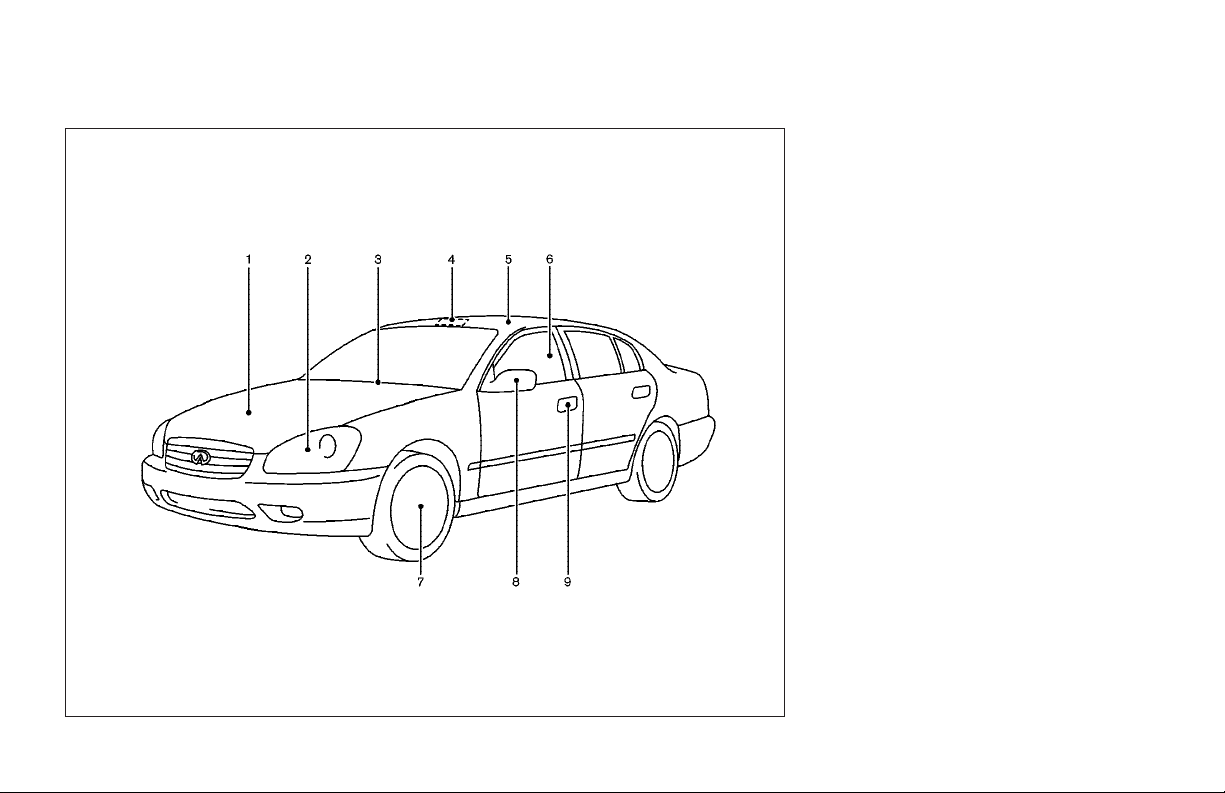
EXTERIOR FRONT
1. Hood (Page 3-9)
2. Headlight and turn signal switch
(P.2-22)/Bulb replacement (P.8-27)
3. Windshield wiper and washer switch
(P.2-20)/Wiper replacement (P.8-20)
4. Interior light (P.2-43)
5. Sunroof (P.2-40)
6. Power windows (P.2-38)
7. Tires
— Wheel and tires (P.8-31, P.9-9)
— Flat tire (P.6-2)
8. Mirrors (P.3-18)
9. Doors
— Keys (P.3-2)
— Door locks (P.3-4)
— Electronic key (P.3-6)
0-2 Illustrated table of contents
SSI0054
Page 7
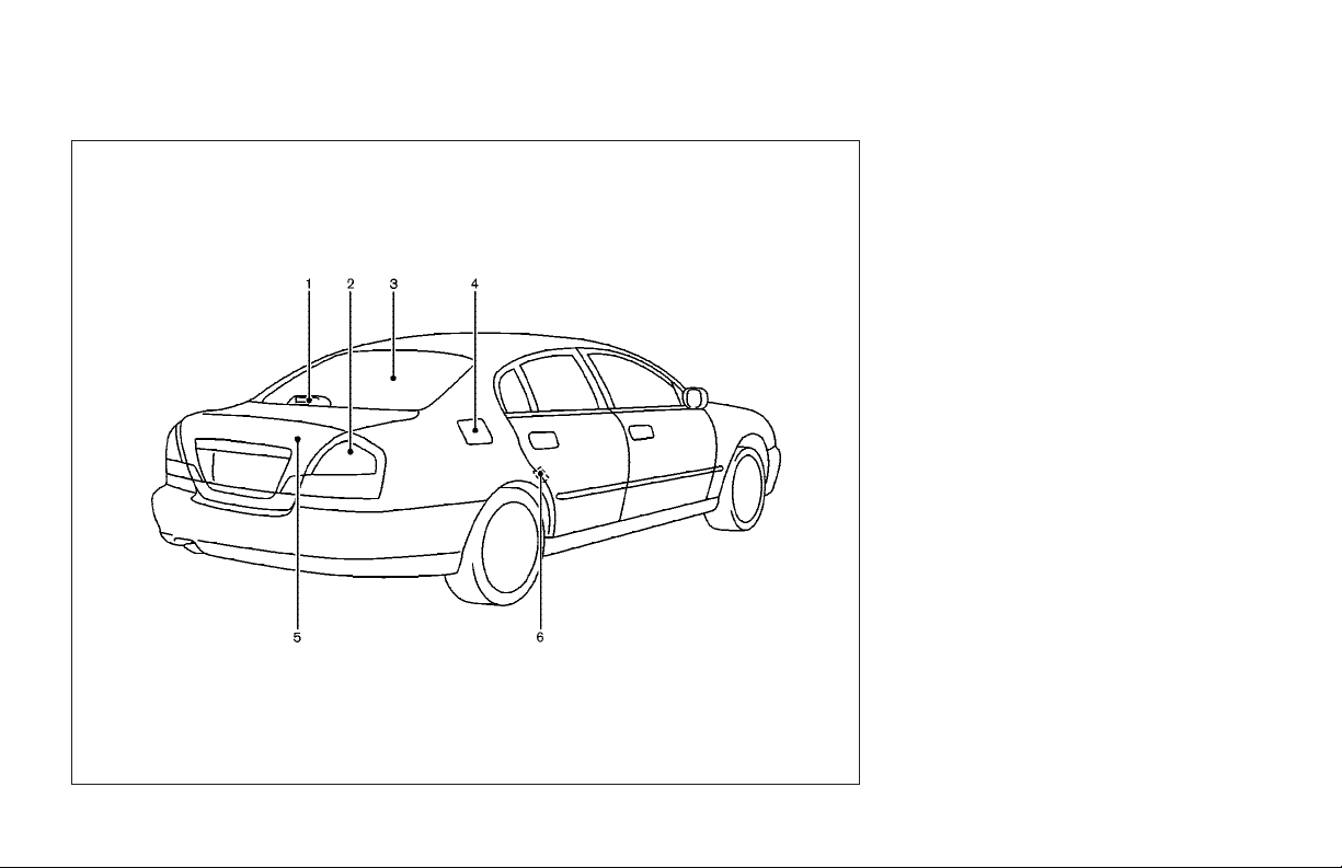
EXTERIOR REAR
1. High-mounted stop light (P.8-28)
2. Side marker, Stop/Tail, Turn signal
light (Bulb replacement) (P.8-28)
3. Rear window defroster switch (P.2-22)
4. Fuel filler lid (P.3-15)/Fuel recommendation (P.9-3)
5. Trunk lid (P.3-10)
6. Child safety locks (P.3-6)
SSI0055
Illustrated table of contents 0-3
Page 8
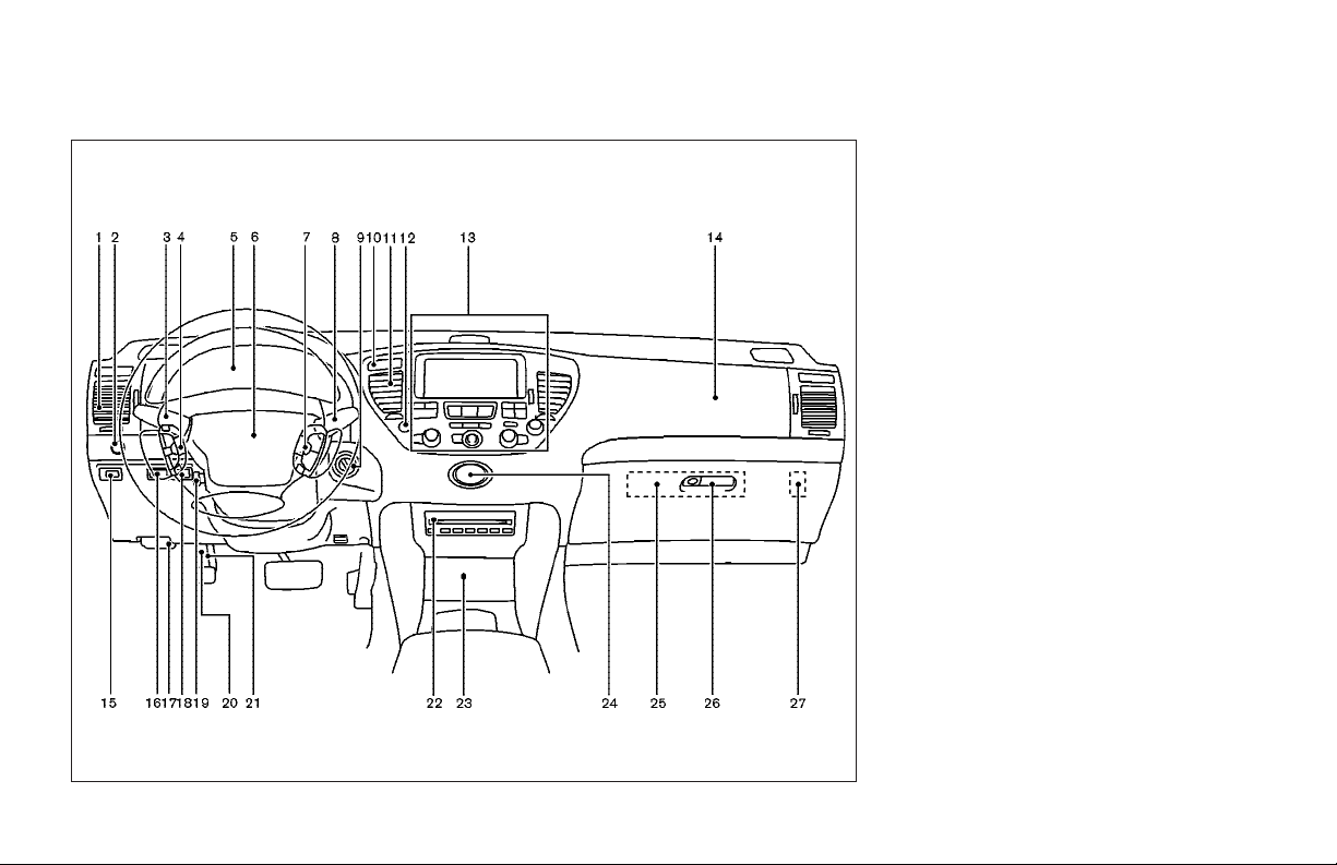
INSTRUMENT PANEL
0-4 Illustrated table of contents
SIC2403
1. Side ventilator (P.4-12)
2. Outside mirror remote control (P.3-19)
3. Headlight/fog light/turn signal switch
(P.2-22)
4. Steering wheel switch for audio con-
trol (P.4-33)
5. Meters and gauges (P.2-3)
6. Driver supplemental air bag (P.1-33)
7. Cruise control main/set switch
(P.5-14)
Intelligent cruise control switch
(P.5-16)
8. Windshield wiper/washer switch
(P.2-20)
9. Ignition switch (P.5-6)
10.Security indicator light (P.2-17)
11.Center ventilator (P.4-12)
12.Hazard warning flasher switch
(P.2-27)
13.Display, Climate and Audio control
switches/buttons (P.4-2)/Navigation
system*
14.Front passenger supplemental air bag
(P.1-33)
15.Instrument brightness control (P.2-26)
16.Vehicle dynamic control OFF switch
(P.2-32)
17.Hood release handle (P.3-9)
Page 9
18.Active damper suspension mode
selector (P.2-31)
19.Tilting/telescopic steering wheel
switch (P.3-16)
20.Fuse box cover (P.8-23)
21.Parking brake pedal/parking brake
release pedal (P.5-14)
22.CD changer (P.4-31)
23.Cigarette lighter and ashtray (P.2-33)
24.Clock (P.2-32)
25.Cassette deck (P.4-29)
26.Glove box (P.2-36)
27.Canceling the power to the trunk
switch (P.3-11)
*: Refer to the separate Navigation
System Owner’s Manual.
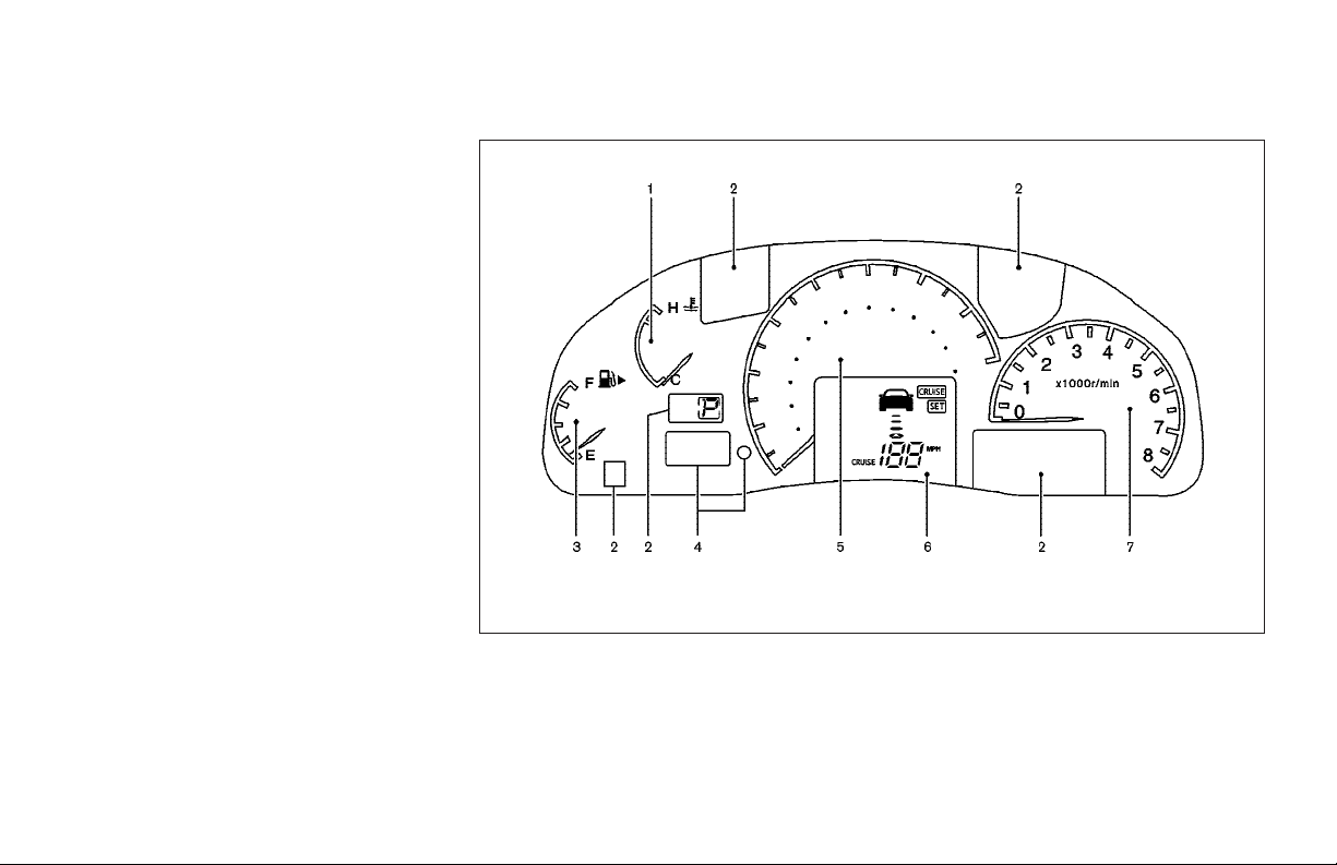
METERS AND GAUGES
SIC2404
1. Engine coolant temperature gauge
(P.2-5)
2. Warming/indicator lights (P.2-10)
3. Fuel gauge (P.2-6)
4. Odometer/twin trip odometer (P.2-4)
5. Speedometer (P.2-4)
6. Cruise control system/Intelligent
cruise control system display (P.2-14)
7. Tachometer (P.2-5)
Illustrated table of contents 0-5
Page 10
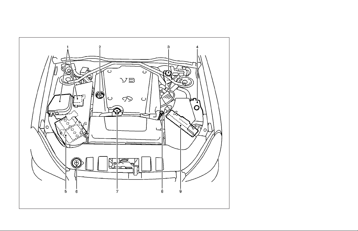
ENGINE COMPARTMENT CHECK
LOCATIONS
1. Fuse/fusible link holder (P.8-23)
2. Engine oil filler cap (P.8-11)
3. Brake fluid reservoir (P.8-14)
4. Coolant reservoir (P.8-9)
5. Battery (P.8-16)
6. Windshield washer fluid reservoir
(P.8-15)
7. Radiator filler cap (P.8-10)
8. Engine oil dipstick (P.8-11)
9. Air cleaner (P.8-19)
0-6 Illustrated table of contents
SDI1642
Page 11

1
Safety — Seats, seat belts and supplemental
restraint system
Seats................................................................ 1-2
Front power seat adjustment....................... 1-2
Rear power seat adjustment (if so
equipped) ................................................... 1-4
Head restraint ............................................. 1-5
Active head restraint (front seats)............... 1-6
Seat belts......................................................... 1-6
Precautions on seat belt usage................... 1-6
Child safety................................................. 1-9
Pregnant women ....................................... 1-10
Injured persons ........................................ 1-10
Pre-crash seat belts (front seats) .............. 1-10
Three-point type seat belt ......................... 1-11
Seat belt extenders................................... 1-14
Seat belt maintenance .............................. 1-14
Child restraints............................................... 1-15
Precautions on child restraints.................. 1-15
Child restraint installation on rear seat center
or outboard positions ............................... 1-17
LATCH (Lower Anchors and Tethers for CHildren)
SYSTEM..................................................... 1-22
Top tether strap child restraint ................. 1-24
Child restraint installation on front passenger
seat .......................................................... 1-25
Booster seats ................................................. 1-28
Precautions on booster seats .................... 1-28
Booster seat installation on rear seat center or
outboard positions.................................... 1-31
Booster seat installation on front passenger
seat .......................................................... 1-32
Supplemental restraint system ....................... 1-33
Precautions on supplemental restraint
system ...................................................... 1-33
Supplemental air bag warning labels........ 1-44
Supplemental air bag warning light .......... 1-44
Page 12
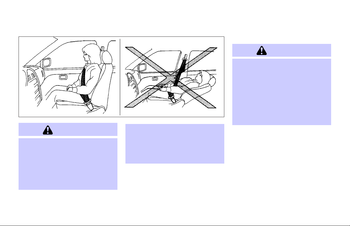
SEATS
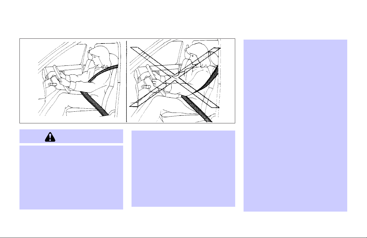
WARNING
O Do not ride in a moving vehicle when
the seatback is reclined. This can be
dangerous. The shoulder belt will not
be against your body. In an accident,
you could be thrown into it and receive
neck or other serious injuries. You
could also slide under the lap belt and
receive serious internal injuries.
SSS0133B
O For the most effective protection when
the vehicle is in motion, the seat
should be upright. Always sit well back
in the seat and adjust the seat belt
properly. See “Precautions on seat belt
usage” later in this section.
FRONT POWER SEAT ADJUSTMENT
WARNING
O Do not adjust the driver’s seat while
driving so full attention may be given
to vehicle operation. The seat may
move suddenly and could cause loss of
control of the vehicle.
O Do not leave children unattended inside
the vehicle. They could unknowingly activate switches or controls. Unattended
children could become involved in serious accidents.
Operating tips
O The seat motor has an auto-reset over-
load protection circuit. If the motor
stops during operation, wait 30 seconds, then reactivate the switch.
O Do not operate the power seat for a
long period of time when the engine is
off. This will discharge the battery.
1-2 Safety — Seats, seat belts and supplemental restraint system
Page 13
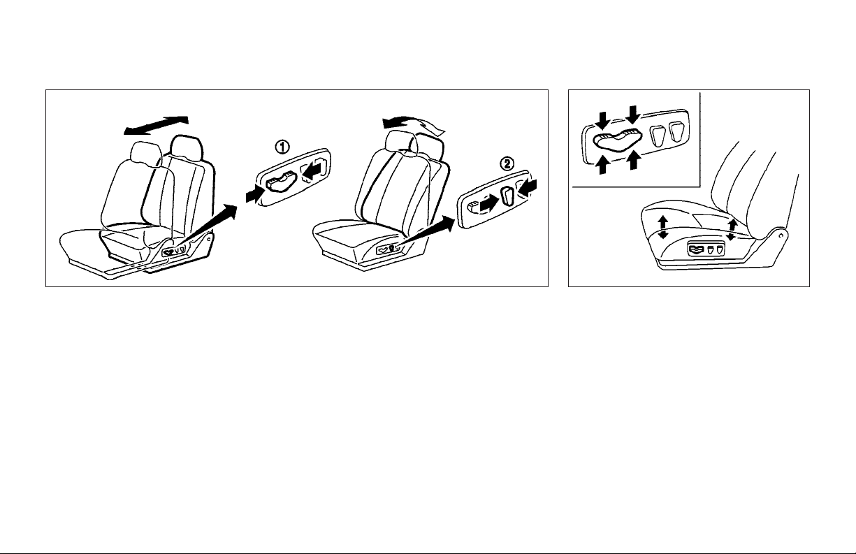
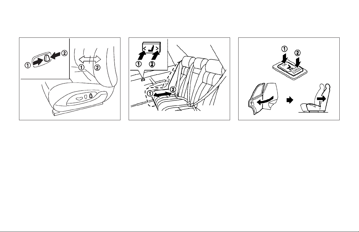
SPA1273C SPA1275A
Forward and backward
Moving the switch
will slide the seat forward or backward to
the desired position.
1
forward or backward
j
Reclining
Move the recline switch
the desired angle is obtained. To bring the
seatback forward again, move the switch
forward.
The reclining feature allows adjustment of
the seatback for occupants of different
sizes for added comfort and to help obtain
proper seat belt fit. (See “Precautions on
2
backward until
j
seat belt usage” later in this section.) The
seatback may also be reclined to allow occupants to rest when the vehicle is parked.
Safety — Seats, seat belts and supplemental restraint system 1-3
Seat lifter
Push the front or rear end of the switch up
or down to adjust the angle and height of
the seat.
Page 14
SPA1276 SSS0324 SPA1586C
Lumbar support (driver’s seat)
The lumbar support feature provides
lower back support to the driver. Move
the lower part of the switch forward or
backward to adjust the seat lumbar area.
REAR POWER SEAT ADJUSTMENT
(if so equipped)
Forward and backward
Push the switch to move the seat forward
1
or backward
j
tinuously while the switch is being
pushed.
1-4 Safety — Seats, seat belts and supplemental restraint system
2
. The seats move con-
j
Entry/exit assist (automatic
return) (if so equipped)
Pushing the ON side
cated on the rear armrest, the automatic
return function will activate.
When a rear door is opened, the rear seat
of the corresponding side automatically
slides all the way back, facilitating ease
of entry and exit.
Pushing the CANCEL side
will deactivate the automatic return function.
1
of the switch lo-
j
2
of the switch
j
Page 15
Automatic reverse operation (for
automatic drive positioner system)
When the driver’s seat is moved backward
by the automatic drive positioner system,
the rear left side seat will automatically
move backward when it is reclined, even
if the rear seat automatic return switch is
in the CANCEL position.
This operation maintains rear passenger
foot and knee space.
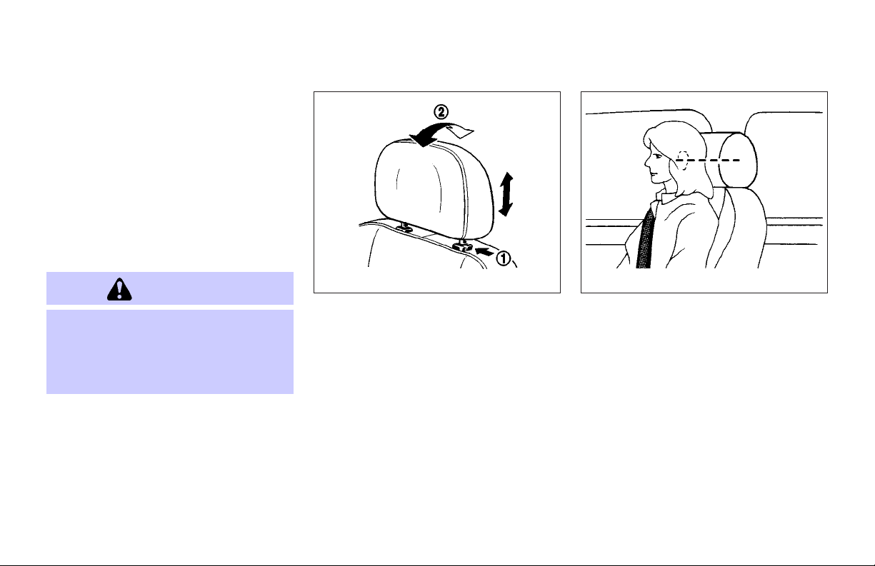
HEAD RESTRAINT
WARNING
Head restraints should be adjusted properly as they may provide significant protection against injury in an accident. Do not
remove them. Check the adjustment after
someone else uses the seat.
SSS0228A SSS0287
To raise the head restraint, pull it up.
To lower, push the lock knob
the head restraint down.
To adjust the head restraint angle
push it in the direction required (except
rear center seat head restraint).
1
and push
j
j
Safety — Seats, seat belts and supplemental restraint system 1-5
Adjust the head restraints as illustrated
so the center is level with the center of
your ears.
2
,
Page 16

SEAT BELTS
SPA1278
ACTIVE HEAD RESTRAINT (front
seats)
WARNING
O Always adjust the head restraints prop-
erly as specified in the previous section. Failure to do so can reduce the effectiveness of the active head restraint.
O Active head restraints are designed to
supplement other safety systems. Always wear seat belts. No system can
prevent all injuries in any accident.
O Do not attach anything to the head re-
straint stalks. Doing so could impair active head restraint function.
The active head restraint moves forward
utilizing the force that the seatback receives from the occupant in a rear-end
collision. The movement of the head restraint helps support the occupant’s head
by reducing its backward movement and
helping absorb some of the forces that
may lead to whiplash type injuries.
Active head restraints are effective for collisions at low to medium speeds in which
it is said that whiplash injury occurs
most.
Active head restraints operate only in certain rear-end collisions. After the collision, the head restraints return to their
original positions.
Properly adjust the active head restraints
as described in the previous section.
PRECAUTIONS ON SEAT BELT
USAGE
If you are wearing your seat belt properly
adjusted, and you are sitting upright and
well back in your seat, your chances of
being injured or killed in an accident
and/or the severity of injury may be
greatly reduced. INFINITI strongly encourages you and all of your passengers
to buckle up every time you drive, even if
your seating position includes a supplemental air bag.
Most U.S. states and Canadian provinces
or territories specify that seat belts be
worn at all times when a vehicle is being
driven.
1-6 Safety — Seats, seat belts and supplemental restraint system
Page 17
WARNING
O Every person who drives or rides in this
vehicle should use a seat belt at all
times. Children should be properly restrained in the rear seat and, if appropriate, in a child restraint.
O The seat belt should be properly ad-
justed to a snug fit. Failure to do so
may reduce the effectiveness of the entire restraint system and increase
SSS0136A
the chance or severity of injury in an
accident. Serious injury or death can
occur if the seat belt is not worn properly.
O Always route the shoulder belt over
your shoulder and across your chest.
Never run the belt behind your back,
under your arm or across your neck.
The belt should be away from your face
and neck, but not falling off your
shoulder.
O Position the lap belt as low and snug
as possible AROUND THE HIPS, NOT
THE WAIST. A lap belt worn too high
could increase the risk of internal injuries in an accident.
O Be sure the seat belt tongue is securely
fastened to the proper buckle.
O Do not wear the seat belt inside out or
twisted. Doing so may reduce its effectiveness.
O Do not allow more than one person to
use the same seat belt.
O Never carry more people in the vehicle
than there are seat belts.
O If the seat belt warning light glows
continuously while the ignition is
turned ON with all doors closed and all
seat belts fastened, it may indicate a
malfunction in the system. Have the
system checked by an INFINITI dealer.
O Once the pre-tensioner seat belt has
activated, it cannot be reused and must
be replaced together with the retractor.
See your INFINITI dealer.
Safety — Seats, seat belts and supplemental restraint system 1-7
Page 18
SSS0134A SSS0016
O Removal and installation of the pre-
tensioner seat belt system components
should be done by an INFINITI dealer.
O All seat belt assemblies, including re-
tractors and attaching hardware,
should be inspected after any collision
by an INFINITI dealer. INFINITI recommends that all seat belt assemblies
in use during a collision be replaced
unless the collision was minor and the
belts show no damage and continue to
Seat belt assemblies not in use during
a collision should also be inspected
and replaced if either damage or improper operation is noted.
O All child restraints and attaching hard-
ware should be inspected after any collision. Always follow the restraint
manufacturer’s inspection instructions
and replacement recommendations. The
child restraints should be replaced if
they are damaged.
operate properly.
1-8 Safety — Seats, seat belts and supplemental restraint system
SSS0014
Page 19

CHILD SAFETY
Children need adults to help protect them.
They need to be properly restrained.
In addition to the general information in
this manual, child safety information is
available from many other sources, including doctors, teachers, government
traffic safety offices, and community organizations. Every child is different, so be
sure to learn the best way to transport your
child.
There are three basic types of child restraint systems:
O Rear facing child restraint
O Front facing child restraint
O Booster seat
The proper restraint depends on the child’s
size. Generally, infants (up to about 1 year
and less than 20 lb (9 kg)) should be
placed in rear facing child restraints. Front
facing child restraints areavailable for children who outgrow rear facing child restraints and are at least 1 year old. Booster
seats are used to help position a vehicle
lap/shoulder belt on a child who can no
longer use a front facing child restraint.
WARNING
Infants and children need specialprotection.
The vehicle’s seat belts may not fit them
properly. The shoulder belt may come too
close to the face or neck. The lap belt may
not fit over their small hip bones. In an accident, an improperly fitting seat belt could
cause serious or fatal injury. Always use appropriate child restraints.
All U.S. states and Canadian provinces or
territories require the use of approved
child restraints for infants and small children. (See “Child restraints” later in this
section.)
Also, there are other types of child restraints available for larger children for additional protection.
INFINITI recommends that all pre-teens
and children be restrained in the rear seat.
According to accident statistics, children
are safer when properly restrained in the
rear seat than in the front seat. This is especially important because your vehicle
has a supplemental restraint system (air
bag system) for the front passenger. See
Safety — Seats, seat belts and supplemental restraint system 1-9
“Supplemental restraint system” earlier in
this section.
Infants
Infants up to at least one year old should
be placed in a rear facing child restraint.
INFINITI recommends that infants be
placed in child restraints that comply with
Federal Motor Vehicle Safety Standards or
Canadian Motor Vehicle Safety Standards.
You should choose a child restraint which
fits your vehicle and always follow the
manufacturer’s instructions for installation
and use.
Small children
Children that are over one year old and
weight between 20 lbs (9 kg) and 40 lbs
(18 kg) can be placed in a forward facing
child restraint. Refer to the manufacturer’s
instructions for minimum and maximum
weight and height recommendations. INFINITI recommends that small children be
placed in child restraints that comply with
Federal Motor Vehicle Safety Standards or
Canadian Motor Vehicle Safety Standards.
You should choosea child restraint thatfits
your vehicle and always follow the manufacturer’s instructions for installation and
use.
Page 20

Larger children
Children who are too large for child restraints should be seated and restrained
by the seat belts which are provided. The
seat belt may not fit properly if the child
is less than 4 feet 9 inches (142.5 cm) tall
and weighs between 40 lbs (18 kg) and
80 lbs (36 kg). A booster seat should be
used to obtain proper seat belt fit.
INFINITI recommends that a child be
placed in a commercially available
booster seat if the shoulder belt in the
child’s seating position fits close to the
face or neck or if the lap portion of the
seat belt goes across the abdomen. The
booster seat should raise the child so
that the shoulder belt is properly positioned across the top, middle portion of
the shoulder and the lap belt is low on
the hips. A booster seat can only be used
in seating positions that have a threepoint type seat belt. The booster seat
should fit the vehicle seat and have a
label certifying that it complies with Federal Motor Vehicle Safety Standards or
Canadian Motor Vehicle Safety Standards.
Once the child has grown so the shoulder
belt is no longer on or near the face and
neck, use the shoulder belt without the
booster seat.
Never let a child stand or kneel on any seat
and do not allow a child in the cargo areas
while the vehicle is moving. The child could
be seriously injured or killed in an accident
or sudden stop.
PREGNANT WOMEN
INFINITI recommends that pregnant
women use seat belts. The seat belt
should be worn snug, and always position
the lap belt as low as possible around the
hips, not the waist, and place the
shoulder belt over your shoulder and
across your chest. Never run the
lap/shoulder belt over your abdominal
area. Contact your doctor for specific recommendations.
INJURED PERSONS
INFINITI recommends that injured persons use seat belts, depending on the injury. Check with your doctor for specific
recommendations.
WARNING
1-10 Safety — Seats, seat belts and supplemental restraint system
PRE-CRASH SEAT BELTS (front
seats)
The pre-crash seat belt tightens the seat
belt to help restrain front seat occupants
under emergency braking. This can help
reduce the risk of injury when a collision
occurs.
Pre-crash seat belts will not activate
when:
O the brake pedal is not depressed
O the seat belt is not fastened
O the shift lever is in the reverse posi-
tion
O the vehicle speed is under 10 mph (15
km/h)
Always wear your seat belt correctly and
sit upright and well back.
If the seat belt warning light blinks even
if the seat belt is fastened, it may indicate
the pre-crash seat belt system has a malfunction. Have your INFINITI dealer check
and repair the system.
Page 21
THREE-POINT TYPE SEAT BELT
WARNING
O Every person who drives or rides in this
vehicle should use a seat belt at all
times.
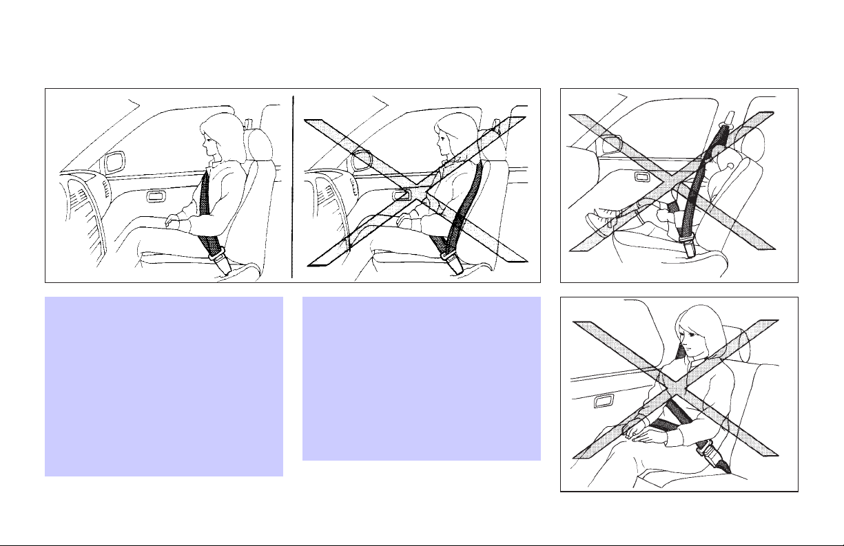
O Do not ride in a moving vehicle when the
seatback is reclined. This can be dangerous. The shoulder belt will not be
against your body. In an accident, you
could be thrown into it and receive neck
or other serious injuries. You could also
slide under the lap belt and receive serious internal injuries.
O For the most effective protection when
the vehicle is in motion, the seat should
be upright. Always sit well back in the
seat and adjust the seat belt properly.
Front seat
SSS0292
Fastening the seat belts
1. Adjust the seat. See “Seats” earlier in
this section.
2. Slowly pull the seat belt out of the retractor and insert the tongue into the
buckle until it clicks.
O The retractor is designed to lock during
a sudden stop or on impact. A slow
pulling motion will permit the belt to
move, and allow you some freedom of
movement in the seat.
Rear seat
SSS0293
O If the seat belt cannot be pulled from
its fully retracted position, firmly pull
the belt and release it. Then smoothly
pull the belt out of the retractor.
Safety — Seats, seat belts and supplemental restraint system 1-11
Page 22
WARNING
When fastening the seat belts, be certain
that seatbacks are completely secured in the
latched position. If they are not completely
secured, passengers may be injured in an accident or sudden stop.
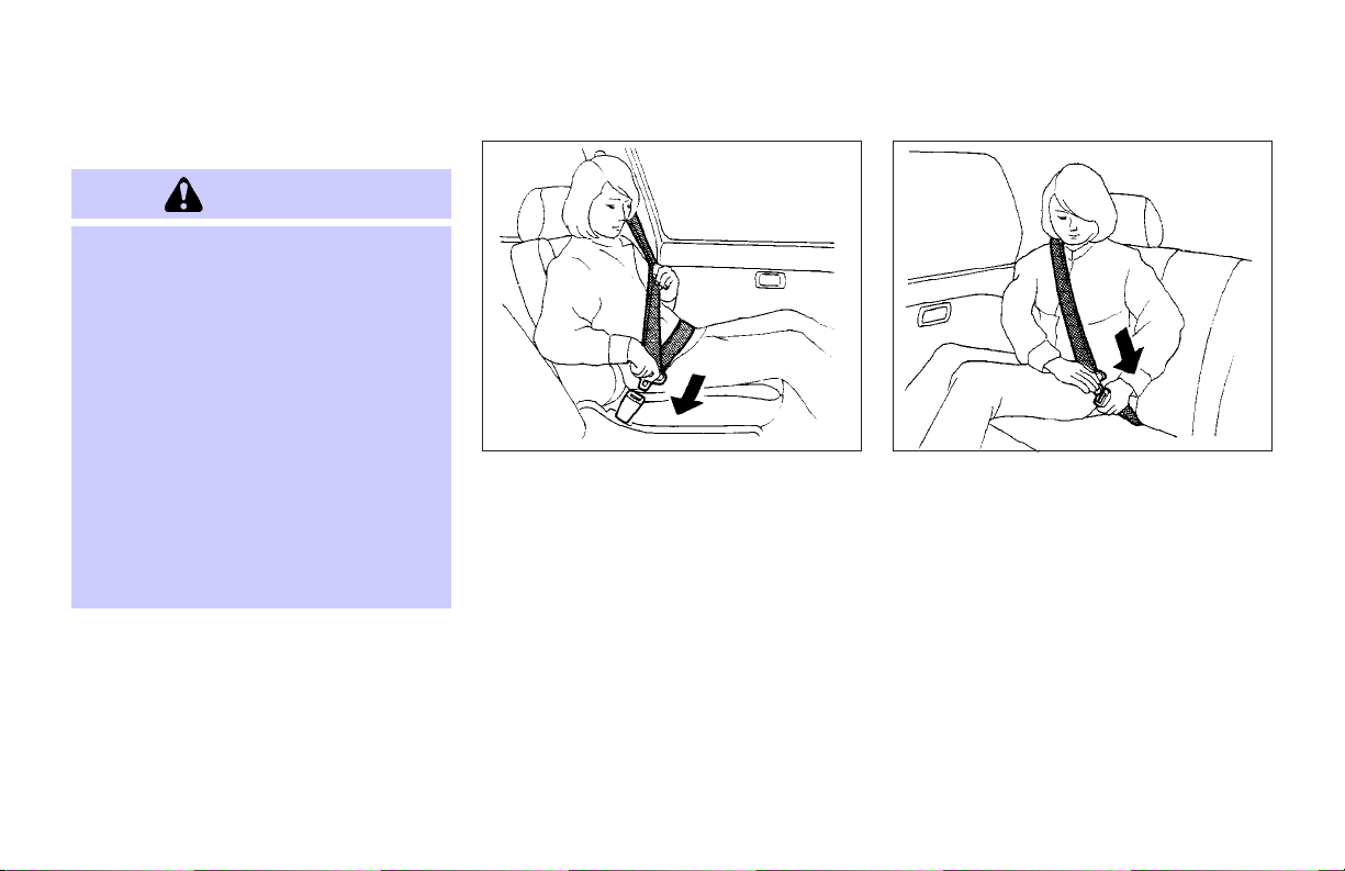
3. Position the lap belt portion low and
Front seat
snug on the hips as shown.
4. Pull the shoulder belt portion toward
the retractor to take up extra slack.
Make sure the shoulder belt is routed
over your shoulder and across your
chest.
The front passenger and rear seat belts
have a locking mechanism for child restraint installation. It is referred to as the
automatic locking mode or child restraint
mode.
SSS0290
When the automatic locking mechanism is
activated the seat belt cannot be extended
again until the seatbelt tongue is detached
from the buckle and fully retracted. Once
retracted, the seat belt is in the emergency
locking mode. For additional information,
see “Child restraints” later in this section.
The automatic locking mode should be
used only for child restraint installation.
During normal seat belt use by an occupant, the locking mode should not be activated. If it is activated it may cause uncomfortable seat belt tension.
1-12 Safety — Seats, seat belts and supplemental restraint system
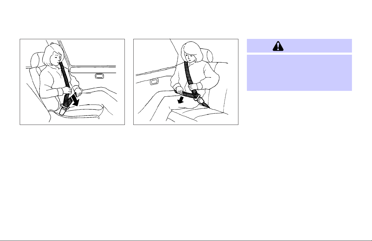
Rear seat
SSS0291A
Page 23
To increase your confidence in the seat
belts, check the operation as follows:
O grasp the shoulder belt and pull for-
ward quickly. The retractor should lock
and restrict further belt movement.
If the retractor does not lock during this
check or if you have any question about
belt operation, see your INFINITI dealer.
SSS0326 SPA1836
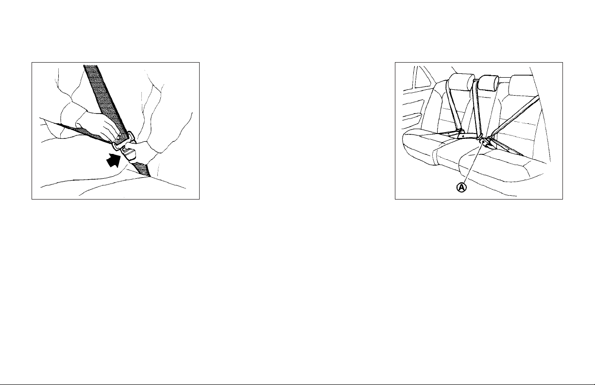
Unfastening the seat belts
To unfasten the belt, push the button on
the buckle. The seat belt will automatically retract.
Checking seat belt operation
Your seat belt retractors are designed to
lock belt movement by two separate
methods:
O when the belt is pulled quickly from
the retractor.
O when the vehicle slows down rapidly.
Center of rear seat
Selecting correct set of seat belts:
The center seat belt buckle is identified
by the CENTER mark
belt tongue can be fastened only into the
center seat belt buckle.
Safety — Seats, seat belts and supplemental restraint system 1-13
A
j
. The center seat
Page 24
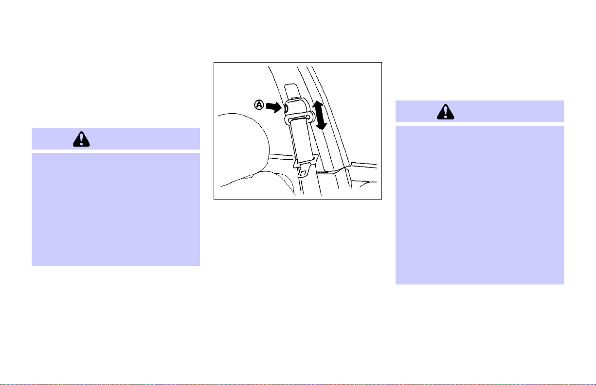
Shoulder belt height adjustment
(front seats)
The shoulder belt anchor height should
be adjusted to the position best for you.
See earlier in “Seat belts” for precautions
on seat belt usage.
WARNING
O After adjustment, release the adjust-
ment button and try to move the shoulder belt anchor up and down to make
sure it is securely fixed in position.
O The shoulder belt anchor height should
be adjusted to the position best for
you. Failure to do so may reduce the effectiveness of the entire restraint
system and increase the chance or severity of injury in an accident.
1-14 Safety — Seats, seat belts and supplemental restraint system
To adjust, push the button
move the shoulder belt anchor to the desired position, so that the belt passes
over the center of the shoulder. The belt
should be away from your face and neck,
but not falling off of your shoulder. Release the button to lock the shoulder belt
anchor into position.
SEAT BELT EXTENDERS
If, because of body size or driving position, it is not possible to properly fit the
lap-shoulder belt and fasten it, an extender is available. The extender adds approximately 8 in (200 mm) of length and
SSS0299A
A
j
, and then
may be used for either the driver or front
passenger seating position. See your
INFINITI dealer for assistance if the extender is required.
WARNING
O Only INFINITI belt extenders, made by
the same company which made the
original equipment seat belts, should
be used with the INFINITI seat belts.
O Adults and children who can use the
standard seat belt should not use an
extender. Such unnecessary use could
result in serious personal injury in the
event of an accident.
O Never use seat belt extenders to install
child restraints. If the child restraint is
not secured properly, the child could be
seriously injured in a collision or a sudden stop.
SEAT BELT MAINTENANCE
O
To clean the seat belt webbings, apply
a mild soap solution or any non-caustic
solution recommended for gently
cleaning cloth upholstery or carpets.
Page 25

CHILD RESTRAINTS
Then brush it, wipe with a cloth and allow it to dry in the shade. Do not allow
the seat belts to retract until they are
completely dry.
O If dirt builds up in the shoulder belt
guide of the seat belt anchors, the
seat belts may retract slowly. Wipe the
shoulder belt guide with a clean, dry
cloth.
O Periodically check to see that the seat
belt and the metal components such
as buckles, tongues, retractors, flexible wires and anchors work properly.
If loose parts, deterioration, cuts or
other damage on the webbing are
found, the entire belt assembly should
be replaced.
PRECAUTIONS ON CHILD
RESTRAINTS
WARNING
O Infants and small children should al-
ways be placed in an appropriate child
restraint while riding in the vehicle.
Failure to use a child restraint can result in serious injury or death.
O Infants and small children should never
be carried on your lap. It is not possible for even the strongest adult to resist the forces of a severe accident. The
child could be crushed between the
adult and parts of the vehicle. Also, do
not put the same seat belt around both
your child and yourself.
O Never install a rear-facing child re-
straint in the front seat. An inflating
supplemental front air bag could seriously injure or kill your child. A rearfacing child restraint must only be used
in the rear seat.
O INFINITI recommends that the child re-
straint be installed in the rear seat.
Safety — Seats, seat belts and supplemental restraint system 1-15
According to accident statistics, children are safer when properly restrained
in the rear seat than in the front seat.
O An improperly installed child restraint
could lead to serious injury or death in
an accident.
In general, child restraints are designed
to be installed with the lap portion of a
lap/shoulder seat belt. In addition, this
vehicle is equipped with a universal child
restraint lower anchor system, referred to
as the LATCH (Lower Anchors and Tethers
for CHildren) system. Some child restraints include two rigid or webbingmounted attachments that can be connected to these lower anchors. For details, see “LATCH (Lower Anchors and
Tether for CHildren) SYSTEM” later in this
section.
Child restraints for infants and children of
various sizes are offered by several manufacturers. When selecting any child restraint system, keep the following points in
mind:
O Choose only a restraint with a label
certifying that it complies with Federal
Motor Vehicle Safety Standard 213 or
Page 26

Canadian Motor Vehicle Safety Standard 213.
O Check the child restraint in your vehicle
to be sureit is compatible withthe vehicle’s seat and seat belt system.
O If the child restraint is compatible with
your vehicle, place your child in the
child restraint and check the various
adjustments to be sure the child restraint is compatible with your child.
Choose a child restraint that is designed for your child’s height and
weight. Always follow all recommended
procedures.
All U.S. states and Canadian provinces or
territories require that infants and small
children be restrained in approved child
restraints at all times while the vehicle is
being operated.
WARNING
O Improper use of a child restraint can in-
crease the risk or severity of injury for
both the childand other occupantsof the
vehicle.
O Follow all of the child restraint manufac-
turer’s instructions for installation and
use. When purchasing a child restraint,
be sure to select one which will fit your
child and vehicle. It may not be possible
to properly install some types of child restraints in your vehicle.
O If the child restraint is not anchored
properly, the risk of a child being injured
in a collision or a sudden stop greatly increases.
O Adjustable seatbacks should be posi-
tioned to fit thechild restraint, butas upright as possible.
O After attaching the child restraint, test it
before you place the child in it. Push it
from side to side. Try to tug it forward
and check to see if the belt holds the restraint in place. The child restraint
should not move more than 1 inch (25
mm). If the restraint is not secure,
tighten the belt as necessary, or put the
restraint in another seat and test it
again. You may need to try a different
child restraint. Not all child restraints
fit in all types of vehicles.
O If you must install a front facing child re-
straint in the front seat, see “Child restraint installation on front passenger
seat” later in this section for details.
O When your child restraint is not in use,
keep it secured with a seat belt to prevent it from being thrown around in case
of a sudden stop or accident.
CAUTION
Remember that a child restraint left in a
closed vehicle can become very hot. Check
the seating surface and buckles before
placing your child in the child restraint.
1-16 Safety — Seats, seat belts and supplemental restraint system
Page 27
CHILD RESTRAINT INSTALLATION
ON REAR SEAT CENTER OR
OUTBOARD POSITIONS
Front facing
WARNING
O The three-point belt in your vehicle is
equipped with an automatic locking
mode retractor which must beused when
installing a child restraint.
O Failure to use the retractor’s locking
mode will result in the child restraint not
being properly secured. The restraint
could tip over or otherwise be unsecured
and cause injury to the child in a sudden
stop or collision.
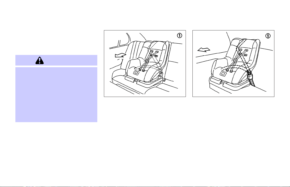
When you install a front facing child restraint in a rear outboard or center seat,
follow these steps:
Rear outboard seat
SSS0278
1. Position the child restraint on the seat.
Always follow the restraint manufacturer’s instructions.
Rear center seat
SSS0252A
2. The back of the child restraint should
be secured against the vehicle seatback. If necessary, adjust or remove
the head restraint to obtain the correct
child restraint fit. See “Head restraint
adjustment” earlier in this section. If
the head restraint is removed, store it
in a secure place. Be sure to install the
head restraint when the child restraint
is removed. If theseating position does
not have an adjustable head restraint
and it is interfering with the proper
child restraint fit, try another seating
position or a different child restraint.
Safety — Seats, seat belts and supplemental restraint system 1-17
Page 28
SSS0253D SSS0254D SSS0332
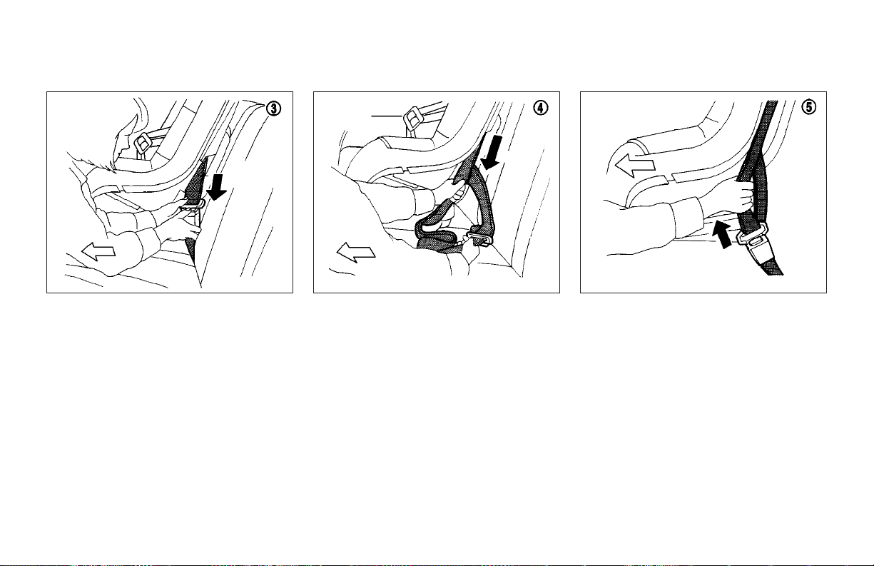
3. Route the seat belt tongue through the
child restraint and insert it into the
buckle until you hear and feel the latch
engage. Be sure to follow the child restraint manufacturer’s instructions for
belt routing.
4. Pull on the shoulder belt until all of the
belt is fully extended. At this time, the
belt retractor isin the automaticlocking
mode (child restraint mode). It reverts
back to emergency locking mode when
the belt is fully retracted.
1-18 Safety — Seats, seat belts and supplemental restraint system
5. Allow the seat belt to retract. Pull up on
the shoulder belt toremove any slack in
the belt.
Page 29
SSS0333
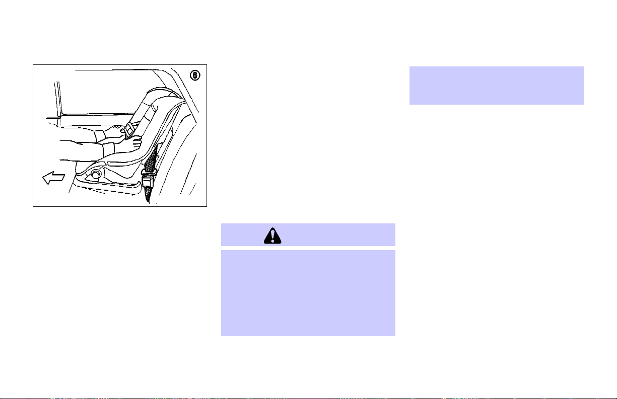
6. Before placing the child in the child restraint, use force to push the child restraint from side to side, and tug it forward to make sure that it is securely
held in place. It should not move more
than 1 inch (25 mm). If it does move
more than 1 inch(25 mm), pull againon
the shoulder belt to further tighten the
child restraint. If unable to properly secure the restraint, move the restraint to
another rear seating position and try
again, or try a different child restraint.
Not all child restraints fit in all types of
vehicles.
7. Check that the retractor is in the auto-
matic locking mode by trying to pull
more seat belt out of the retractor. If
you cannot pull any moreseat belt webbing out of the retractor, the retractor is
in the automatic locking mode.
8. Check to make sure that the child restraint is properly secured prior to each
use. If the seat belt is not locked, repeat steps 3 through 7.
After the child restraint is removed and the
seat belt is fully retracted, the automatic
locking mode (child restraint mode) is canceled.
Rear facing
WARNING
O The three-point belt in your vehicle is
equipped with an automatic locking
mode retractor which must beused when
installing a child restraint.
O Failure to use the retractor’s locking
mode will result in the child restraint not
being properly secured. The re-
Safety — Seats, seat belts and supplemental restraint system 1-19
straint could tip over or otherwise be unsecured and cause injury to the child in a
sudden stop or collision.
When you install a rear facing child restraint in the rear seat, follow these steps:
Page 30
Rear outboard seat
SSS0334
Rear center seat
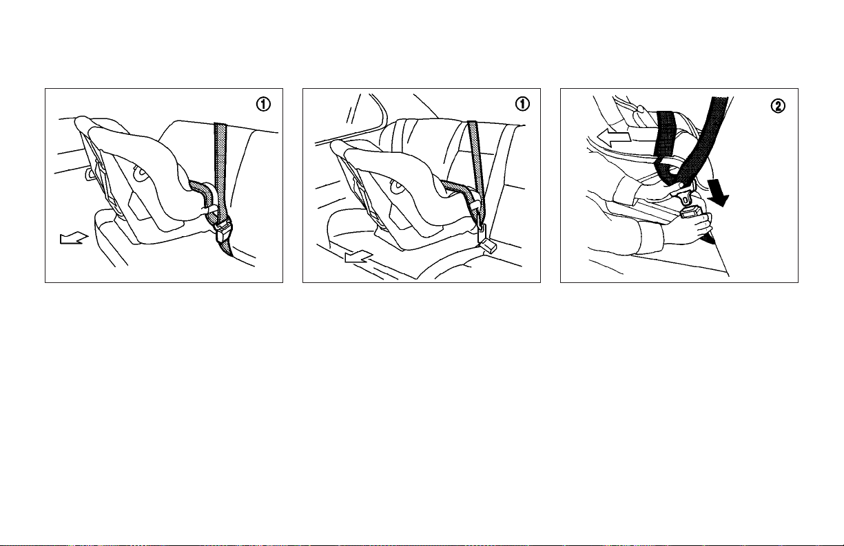
1. Position the child restraint on the seat.
Always follow the restraint manufacturer’s instructions.
1-20 Safety — Seats, seat belts and supplemental restraint system
SSS0279A
SSS0335
2. Route the seat belt tongue through the
child restraint and insert it into the
buckle until you hear and feel the latch
engage. Be sure to follow the child restraint manufacturer’s instructions for
belt routing.
Page 31

SSS0258A SSS0259A SSS0260A
3. Pull on the shoulder belt until all of the
belt is fully extended. At this time, the
seat belt retractor is in the automatic
locking mode (child restraint mode). It
reverts back to emergency locking
mode when the belt is fully retracted.
4. Allow the seat belt to retract. Pull up on
the shoulder belt toremove any slack in
the belt.
Safety — Seats, seat belts and supplemental restraint system 1-21
5. Before placing the child in the child restraint, use force to push the child restraint from side to side, and tug it forward to make sure that it is securely
held in place. It should not move more
than 1 inch (25 mm). If it does move
more than 1 inch(25 mm), pull againon
the shoulder belt to further tighten the
child restraint. If unable to properly secure the restraint, move the restraint to
another rear seating position and try
again, or try a different child restraint.
Not all child restraints fit in all types of
vehicles.
Page 32

6. Check that the retractor is in the automatic locking mode by trying to pull
more belt out of the retractor. If you
cannot pull any more belt webbing out
of the retractor, the retractor is in the
automatic locking mode.
7. Check to make sure that the child restraint is properly secured prior to each
use. If the seat belt is not locked, repeat steps 3 through 6.
After the child restraint is removed and the
seat belt is fully retracted, the automatic
locking mode (child restraint mode) is canceled.
SSS0327
LATCH (Lower Anchors and Tethers
for CHildren) SYSTEM
1. LATCH Lower anchor points (right)
2. LATCH Lower anchor points (left)
3. LATCH Label
(1 and 2 are located in the space between
the seatback and seat cushion)
WARNING
O Attach LATCH system compatible child
restraints only at the locations shown. If
a child restraint is not secured properly,
your child could be seriously injured or
killed in an accident.
O Do not secure achild restraint in the cen-
ter rear seating position using the LATCH
system anchors. The child restraint will
not be secured properly.
O The LATCH system anchors are designed
to withstand only those loads imposed
by correctly fitted child restraints. Under
no circumstance are they to be used for
adult seat belts or harnesses.
Some child restraints include two rigid or
webbing-mounted attachments that can be
connected to two anchors located at certain seating positions in your vehicle. This
system is known as the LATCH (Lower Anchors and Tethers for CHildren) system.
This system may also be referred to as the
ISOFIX or ISOFIX compatible system.
1-22 Safety — Seats, seat belts and supplemental restraint system
Page 33

With this system, you do not have to use a
vehicle seat belt to secure the child restraint. Your vehicle is equipped with special anchor points that areused with LATCH
system compatible child restraints. Check
your child restraint fora label stating thatit
is compatible with the LATCH system. This
information may also be in the child restraint owner’s manual. If you have such a
child restraint, refer to the illustration for
the seating positions equipped with LATCH
system anchors which can be used to secure the child restraint.
The LATCH system anchors are located at
the rear of the seat cushion near the seatback. A label is attached to the seatback to
help you locate the LATCH system anchors.
Some child restraints may also require the
use of a top tether strap. See “Top tether
strap child restraint” later in this section
for installation instructions.
When installing a child restraint, carefully
read and follow the instructions in this
manual and those supplied with the child
restraint.
When you install a LATCH system compatible child restraint to the lower anchor attachments, follow these steps.
WARNING
Inspect the lower anchors by inserting your
fingers into the lower anchor area and
feeling to make sure there are no obstructions over the LATCH system anchors, such
as seat belt webbing or seat cushion material. The child restraint will not be secured
properly if the LATCH system anchors are obstructed.
1. To install the LATCH system compatible
child restraint, insert the child restraint
LATCH system anchor attachments into
the anchor points on the rear seat. If
the child restraint is equipped with a
top tether, see “Top tether strap child
restraint” later in this section for installation instructions.
2. After attaching the child restraint and
before placing the child in it, use force
to push the child restraint from side to
side and tug it forward to make sure
that the child restraint is securely held
in place. It should not move more than
1 inch (25 mm).
3. Check to make sure that the child re-
Safety — Seats, seat belts and supplemental restraint system 1-23
straint is properly secured prior to each
use.
Page 34

SSS0328
TOP TETHER STRAP CHILD
RESTRAINT
WARNING
O Child restraint anchor points are de-
signed to withstand only those loads
imposed by correctly fitted child restraints. Under no circumstances are
they to be used for adult seat belts or
harnesses.
O After removing a rear seat head re-
straint for top tether installation, store
it securely to prevent it from causing
injury to passengers or damage to the
vehicle in case of sudden braking or an
accident. Always replace it and adjust
properly when top tether is no longer in
use.
If your child restraint has a top tether
strap, it must be secured to the anchor
point provided behind its position.
First, adjust the seatback so that it is upright. Then secure the child restraint with
the rear seat belt or the LATCH system
(outboard positions), as applicable.
Remove the head restraint from the seatback. Store it in a secure place. Position
the top tether strap over the top of the
seatback and secure it to the tether anchor bracket that provides the straightest
installation. Tighten the tether strap according to the manufacturer’s instruction
to remove any slack.
For best child restraint fit, see the child
restraint installation instructions in this
section and the child restraint manufacturer’s instructions.
Anchor point locations
Anchor points
rear parcel shelf finisher.
1
Anchor point for rear driver’s side
j
seat
2
Anchor point for rear center seat
j
3
Anchor point for rear right side seat
j
4
Anchor point lid. To open, pull up the
j
anchor point lid.
5
Anchor point
j
If you have any questions when installing a top strap child restraint on the
rear seat, consult your INFINITI dealer
for details.
5
are located under the
j
1-24 Safety — Seats, seat belts and supplemental restraint system
Page 35

SSS0300A
mode retractor which must beused when
installing a child restraint.
O Failure to use the retractor’s locking
mode will result in the child restraint not
being properly secured. The child restraint could tip over or otherwise be unsecured and cause injury to the child in a
sudden stop or collision.
If you must install a child restraint in the
front seat, follow these steps:
CHILD RESTRAINT INSTALLATION
ON FRONT PASSENGER SEAT
WARNING
O Never install a rear-facing child restraint
in the front passenger seat. Supplemental front air bags inflate with great
force. A rear-facing child restraint could
be struck by the supplemental front air
bag in a crash and could seriously injure
or kill your child.
O INFINITI recommends that child re-
straints be installed in the rear seat.
However, if you must install a forwardfacing child restraint in the front passenger seat, move the passenger seat to the
rearmost position.
O A child restraint with a top tether strap
should not be used in the front passenger seat.
O The three-point belt in your vehicle is
equipped with an automatic locking
Safety — Seats, seat belts and supplemental restraint system 1-25
Page 36

adjustment” earlier in this section. If
the head restraint is removed, store it
in a secure place. Be sure to install the
head restraint when the child restraint
is removed. If theseating position does
not have an adjustable head restraint
and it is interfering with the proper
child restraint fit, try another seating
position or a different child restraint.
SSS0301B SSS0253D
1. Position the child restraint on the front
passenger seat. It should be placed in
a front facing direction only. Move the
seat to the rear most position. Adjust
the head restraint to its highest position. Always follow the child restraint
manufacturer’s instructions. Child re-
straints for infants must be used in the
rear facing direction and therefore
must not be used in the front seat.
2. The back of the child restraint should
be secured against the vehicle seatback. If necessary, adjust or remove
the head restraint to obtain the correct
child restraint fit. See “Head restraint
1-26 Safety — Seats, seat belts and supplemental restraint system
3. Route the seat belt tongue through the
child restraint and insert it into the
buckle until you hear and feel the latch
engage.
Be sure to follow the child restraint
manufacturer’s instructions for belt
routing.
Page 37

SSS0254D SSS0331 SSS0302B
4. Pull on the shoulder belt until all of the
belt is fully extended. At this time, the
belt retractor isin the automaticlocking
mode (child restraint mode). It reverts
back to emergency locking mode when
the belt is fully retracted.
5. Allow the seat belt to retract. Pull up
on the shoulder belt to remove any
slack in the belt.
Safety — Seats, seat belts and supplemental restraint system 1-27
A
6. Before placing the child in the child re-
j
straint, use force to push the child restraint from side to side, and tug it forward to make sure that it is securely
held in place. It should not move more
than 1 inch (25 mm). If it does move
more than 1 inch(25 mm), pull againon
the shoulder belt to further tighten the
child restraint. If unable to properly secure the restraint, move the restraint to
another rear seating position and try
again, or try a different child restraint.
Not all child restraints fit in all types of
vehicles.
Page 38

BOOSTER SEATS
7. Check that the retractor is in the automatic locking mode by trying to pull
more belt out of the retractor. If you
cannot pull any more belt webbing out
of the retractor, the retractor is in the
automatic locking mode.
8. Check to make sure that the child restraint is properly secured prior to each
use. If the seat belt is not locked, repeat steps 3 through 7.
After the child restraint is removed and the
seat belt is fully retracted, the automatic
locking mode (child restraint mode) is canceled.
PRECAUTIONS ON BOOSTER SEATS
WARNING
O Infants andsmall children shouldalways
be placed in an appropriate child restraint while riding in the vehicle. Failure
to use a child restraint or booster seat
can result in serious injury or death.
O Infants and small children should never
be carried on your lap. It is not possible
for even the strongest adult to resist the
forces of a severe accident. The child
could be crushed between the adult and
parts of the vehicle. Also, do not put the
same seat belt around both your child
and yourself.
O INFINITI recommends that the booster
seat be installed in the rear seat. According to accident statistics, children are
safer when properly restrained in the
rear seat than in the frontseat.
O A booster seat must only be installed in a
seating position that has a lap/shoulder
belt. Failure to use a three-point type
seat belt witha booster seat canresult in
a serious injury in sudden stop or collision.
O An improperly installed booster seat
could lead to serious injury or death in
an accident.
1-28 Safety — Seats, seat belts and supplemental restraint system
Page 39

LRS0455 LRS0453
WARNING
Do not use towels, books, pillows or other
items in place of a booster seat. Items
such as these may move during normal
driving or a collision and result in serious
injury or death. Booster seats are designed
to be used with a lap/shoulder belt.
Booster seats are designed to properly
route the lap and shoulder portions of the
seat belt over the strongest portions of a
child’s body to provide the maximum protection during a collision.
Booster seats of various sizes are offered
by several manufacturers. When selecting
any booster seat, keep the following
points in mind:
O Choose only a booster seat with a
label certifying that it complies with
Federal Motor Vehicle Safety Standard
213 or Canadian Motor Vehicle Safety
Standard 213.
O Check the booster seat in your vehicle
to be sure it is compatible with the vehicle’s seat and seat belt system.
Safety — Seats, seat belts and supplemental restraint system 1-29
Page 40

seat is compatible with your child. Always follow all recommended procedures.
All U.S. states and provinces of Canada
require that infants and small children be
restrained in an approved child restraint
at all times while the vehicle is being operated.
WARNING
O Improper use of a booster seat can in-
LRS0464
O Make sure the child’s head will be
properly supported by the booster
seat or vehicle seat. The seatback
must be at or above the center of the
child’s ears. For example, if a low back
booster seat
seatback must be at or above the center of the child’s ears. If the seatback
is lower than the center of the child’s
ears, a high back booster seat
should be used.
O If the booster seat is compatible with
your vehicle, place your child in the
booster seat and check the various
adjustments to be sure the booster
1
is chosen, the vehicle
j
j
2
1-30 Safety — Seats, seat belts and supplemental restraint system
crease the risk or severity of injury for
both the child and other occupants of
the vehicle.
O Follow all of the booster seat manufac-
turer’s instructions for installation and
use. When purchasing a booster seat,
be sure to select one which will fit your
child and vehicle. It may not be possible to properly install some types of
booster seats in your vehicle.
O If the booster seat and seat belt are
not used properly, the risk of a child
being injured in a collision or a sudden
stop greatly increases.
O Adjustable seatbacks should be posi-
tioned to fit the booster seat, but as
upright as possible.
O After placing the child in the booster
seat and fastening the seat belt, make
sure the shoulder portion of the belt is
away from the child’s face and neck
and the lap portion of the belt does not
cross the abdomen.
O Do not put the shoulder belt behind the
child or under the child’s arm. If you
must install a booster seat in the front
seat, see “Booster seat installation on
front passenger seat” later in this section.
O When your booster seat is not in use,
keep it secured with a seat belt to prevent it from being thrown around in
case of a sudden stop or accident.
CAUTION
Remember that a booster seat left in a
closed vehicle can become very hot. Check
Page 41

the seating surface and buckles before
placing your child in the booster seat.
Center position
Safety — Seats, seat belts and supplemental restraint system 1-31
LRS0451
Outboard position
LRS0452
BOOSTER SEAT INSTALLATION ON
REAR SEAT CENTER OR OUTBOARD
POSITIONS
CAUTION
Do not use the lap/shoulder belt automatic
locking mode whenusing a boosterseat with
the seat belts. When you install a booster
seat in the rear seat, follow these steps:
1. Position the booster seat on the seat.
Page 42

Only place it in a front facing direction. Always follow the booster seat
manufacturer’s instructions.
2. The booster seat should be positioned
on the vehicle seat so that it is stable.
If necessary, adjust or remove the
head restraint to obtain the correct
booster seat fit. See “Head restraint
adjustment” earlier in this section. If
the head restraint is removed, store it
in a secure place. Be sure to install
the head restraint when the booster
seat is removed. If the seating position does not have an adjustable head
restraint and it is interfering with the
proper booster seat fit, try another
seating position or a different booster
seat.
3. Position the lap portion of the seat
belt low and snug on the child’s hips.
Be sure to follow the booster seat
manufacturer’s instructions for adjusting the belt routing.
4. Pull the shoulder belt portion of the
seat belt toward the retractor to take
up extra slack. Be sure the shoulder
belt is positioned across the top,
middle portion of the child’s shoulder.
Be sure to follow the booster seat
manufacturer’s instructions for adjusting the belt routing.
5. Follow the warnings, cautions and instructions for properly fastening a seat
belt shown in the “Three-point seat
belt with retractor” earlier in this section.
1-32 Safety — Seats, seat belts and supplemental restraint system
LRS0454
BOOSTER SEAT INSTALLATION ON
FRONT PASSENGER SEAT
WARNING
INFINITI recommends that child restraints
be installed in the rear seat. However, if
you must install a booster seat in the front
passenger seat, move the passenger seat
to the rearmost position.
If you must install a booster seat in the
front seat, follow these steps:
Page 43

SUPPLEMENTAL RESTRAINT SYSTEM
1. Move the seat to the rearmost position.
2. Position the booster seat on the seat.
Only place it in a front facing direction. Always follow the booster seat
manufacturer’s instructions.
3. The booster seat should be positioned
on the vehicle seat so that it is stable.
If necessary, adjust or remove the
head restraint to obtain the correct
booster seat fit. See “Head restraint
adjustment” earlier in this section. If
the head restraint is removed, store it
in a secure place. Be sure to install
the head restraint when the booster
seat is removed. If the seating position does not have an adjustable head
restraint and it is interfering with the
proper booster seat fit, try another
seating position or a different booster
seat.
4. Position the lap portion of the seat
belt low and snug on the child’s hips.
Be sure to follow the booster seat
manufacturer’s instructions for adjusting the belt routing.
5. Pull the shoulder belt portion of the
seat belt toward the retractor to take
up extra slack. Be sure the shoulder
belt is positioned across the top,
middle portion of the child’s shoulder.
Be sure to follow the booster seat
manufacturer’s instructions for adjusting the belt routing.
6. Follow the warnings, cautions and instructions for properly fastening a seat
belt shown in the “Three-point seat
belt with retractor” earlier in this section.
Safety — Seats, seat belts and supplemental restraint system 1-33
PRECAUTIONS ON SUPPLEMENTAL
RESTRAINT SYSTEM
This Supplemental Restraint System (SRS)
section contains important information
concerning the driver and passenger front
impact supplemental air bags, front seat
side-impact supplemental air bags, curtain side-impact air bags and front seat
pre-tensioner seat belts.
Supplemental front impact air bag
system: This system can help cushion the
impact force to the face and chest of the
driver and front passenger in certain frontal collisions.
Supplemental side-impact air bag
system: This system can help cushion the
impact force to the chest area of the
driver and front passenger in certain side
impact collisions. The front seat sideimpact supplemental air bags are designed to inflate on the side where the vehicle is impacted.
Supplemental side-impact curtain air bag
system: This system can help cushion the
impact force to the head of occupants in
front and rear outboard seating positions
in certain side impact collisions. The curtain side-impact air bags are designed to
inflate on the side where the vehicle is
impacted.
Page 44

These supplemental restraint systems are
designed to supplement the crash protection provided by the driver and passenger
seat belts and are not a substitute for
them. Seat belts should always be correctly worn and the occupant seated a
suitable distance away from the steering
wheel, instrument panel and door finishers. (See “Seat belts” earlier in this
section for instructions and precautions
on seat belt usage.)
After turning the ignition key to the ON
position, the supplemental air bag
warning light illuminates. The supplemental air bag warning light will turn off
after about 7 seconds if the systems are
operational.
WARNING
O The supplemental front air bags ordi-
narily will not inflate in the event of a
side impact, rear impact, rollover, or
lower severity frontal collision. Always
wear your seat belts to help reduce the
risk or severity of injury in various
kinds of accidents.
O The seat belts and the supplemental
front air bags are most effective when
SSS0131B
you are sitting well back and upright in
the seat. The front air bags inflate with
great force. If you are unrestrained,
leaning forward, sitting sideways or out
of position in any way, you are at
greater risk of injury or death in a
crash. You may also receive serious or
fatal injuries from the supplemental
front air bag if you are up against it
when it inflates. Always sit back
against the seatback and as far away
as practical from the steering wheel or
1-34 Safety — Seats, seat belts and supplemental restraint system
Page 45

instrument panel. Always use the seat
belts.
O The driver and front passenger seat
belt buckles are equipped with sensors
that detect if the seat belts are fastened. The air bag system monitors the
severity of a collision and then inflates
the air bags based on belt usage.
Failure to properly wear seat belts can
increase the risk or severity of injury in
an accident.
O Keep hands on the outside of the steer-
ing wheel. Placing them in side the
steering wheel rim could increase the
risk that they are injured when the
supplemental front air bag inflates.
SSS0132B
Safety — Seats, seat belts and supplemental restraint system 1-35
Page 46

SSS0007
SSS0008
SSS0099
SSS0006
1-36 Safety — Seats, seat belts and supplemental restraint system
SSS0009
SSS0100
Page 47

WARNING
O Never let children ride unrestrained or
extend their hands or face out of the
window. Do not attempt to hold them in
your lap or arms. Some examples of
dangerous riding positions are shown
in the illustrations.
O Children may be severely injured or
killed when the supplemental front air
bags, side air bags or curtain sideimpact air bags inflate if they are not
properly restrained. Pre-teens and children should be properly restrained in
the rear seat, if possible.
O Also, never install a rear facing child re-
straint in the front seat. An inflating
supplemental front air bag could seriously injure or kill your child. See
“Child restraints” earlier in this section
for details.
SSS0059A SSS0188A
Safety — Seats, seat belts and supplemental restraint system 1-37
Page 48

SSS0140 SSS0159
WARNING
Supplemental side air bag and curtain sideimpact air bag:
O The supplemental side air bag and cur-
tain side-impact air bag ordinarily will
not inflate in the event of a frontal impact, rear impact, rollover or lower severity side collision. Always wear your
seat belts to help reduce the risk or severity of injury in various kinds of
accidents.
O The seat belts, the supplemental side
air bags and curtain side-impact air
bags are most effective when you are
sitting well back and upright in the
seat. The side air bag and curtain sideimpact air bag inflate with great force.
Do not allow anyone to place their
hand, leg or face near the side air bag
on the side of the seatback of the front
seat or near the side roof rails. Do not
allow anyone sitting in the front seats
or rear outboard seats to extend their
hand out of the window or lean against
the door. Some examples of dangerous
riding positions are shown in the previous illustrations.
O When sitting in therear seat, do not hold
onto the seatbackof the frontseat. If the
supplemental side air bag inflates, you
may be seriously injured. Be especially
careful with children, who shouldalways
be properly restrained. Some examples
of dangerous riding positions are shown
in the illustrations.
SSS0162
1-38 Safety — Seats, seat belts and supplemental restraint system
Page 49

O Do not use seat covers on the front
seatbacks. They may interfere with
supplemental side air bag inflation.
SSS0325
1. Crash zone sensor
2. Supplemental curtain side-impact air
bags
3. Supplemental side air bag modules
4. Pre-crash seat belt sensor
5. Supplemental front air bag modules
Safety — Seats, seat belts and supplemental restraint system 1-39
6. Diagnosis sensor unit
7. Seat belt pre-tensioner retractor
8. Satellite sensors
9. Supplemental curtain side-impact air
bag modules
Page 50

Supplemental front air bag
system
The driver supplemental air bag is located
in the center of the steering wheel; the
front passenger supplemental air bag is
mounted in the instrument panel above
the glove box. These systems are designed to meet optional certification requirements under U.S. regulations. They
are also permitted in Canada. The optional certification allows front air bags to
be designed to inflate somewhat less
forcefully than previously. However, all of
the information, cautions and warnings in
this manual still apply and must be followed. The front air bags are designed to
inflate in higher severity frontal collisions,
although they may inflate if the forces in
another type of collision are similar to
those of a higher severity frontal impact.
They may not inflate in certain frontal collisions. Vehicle damage (or lack of it) is
not always an indication of proper supplemental air bag operation.
The supplemental air bag system has dual
stage inflators for both the driver and passenger air bags. The system monitors information from the crash zone sensor, the
diagnosis sensor unit and seat belt buckle
sensors that detect if the seat belts are
fastened, inflator operation is based on
the severity of a collision and whether the
seat belts are being used. Only one front
air bag may inflate in a crash, depending
on the crash severity and whether the front
occupants are belted or unbelted. This
does not indicate improper performance of
the system. If you have any questions
about the performance of your air bag system, please contact your INFINITI dealer.
When the supplemental front air bag inflates, a fairly loud noise may be heard,
followed by release of smoke. This smoke
is not harmful and does not indicate a fire.
Care should be taken not to inhale it, as it
may cause irritation and choking. Those
with a history of a breathing condition
should get fresh air promptly.
Supplemental front air bags, along with
the use of seat belts, help to cushion the
impact force on the face and chest of the
front occupants. They can help save lives
and reduce serious injuries. However, an
inflating front air bag may cause facial
abrasions or other injuries. Front air bags
do not provide restraint to the lower
body.
The seat belts should be correctly worn and
the driver and passenger seated upright as
1-40 Safety — Seats, seat belts and supplemental restraint system
far as practical away from the steering
wheel or instrument panel. The supplemental front air bags inflate quickly in order
to help protect the front occupants. Because
of this, the force of the front air bag inflating can increase the risk of injury if the
occupant is too close to or is against the air
bag module during inflation. The air bag will
deflate quickly after the collision is over.
WARNING
O Do not place any objects on the
steering wheel pad or on the instrument panel. Also, do not place any objects between any occupant and the
steering wheel or instrument panel.
Such objects may become dangerous
projectiles and cause injury if the
supplemental front air bag inflates.
O Immediately after inflation, several
front air bag system components will
be hot. Do not touch them; you may severely burn yourself.
O No unauthorized changes should be
made to any components or wiring of
the supplemental front air bag system.
Page 51

This is to prevent accidental inflation of
the supplemental air bag or damage to
the supplemental air bag system.
O Do not make unauthorized changes to
your vehicle’s electrical system, suspension system or front end structure. This
could affect proper operation of the
supplemental front air bag system.
O Tampering with the supplemental front
air bag system may result in serious personal injury. Tampering includes
changes to the steering wheel and the
instrument panel assembly by placing
material over the steering wheelpad and
above the instrument panel, or by installing additional trim material around
the air bag system.
O Work around and on the supplemental
front air bag system should be done by
an INFINITI dealer. Installation of electrical equipment should also be done by
an INFINITI dealer. The Supplemental
RestraintSystem (SRS)wiring should not
be modified or disconnected. Unauthorized electrical test equipment and prob-
ing devices should not be usedon the air
bag system.
O A cracked windshield should be replaced
immediately by a qualified repair facility.
A cracked windshield could affect the
function of the supplemental air bag
system.
When selling your vehicle, we request that
you inform the buyer about the supplemental front airbag system andguide the buyer
to the appropriate sections in this Owner’s
Manual.
Safety — Seats, seat belts and supplemental restraint system 1-41
SSS0190
Supplemental side air bag and
curtain side-impact air bag system
The supplemental side air bags are located
in the outside of the seatback of the front
seats. The supplemental curtain sideimpact air bags are located in the side roof
rails. These systems are designed to meet
voluntary guidelines to helpreduce the risk
of injury toout-of-position occupants. How-
ever, all of the information, cautions and
warnings in this manual still apply and
must be followed. The supplemental side
air bags and curtain side-impact air bags
are de-
Page 52

signed to inflate in higher severity side
collisions, although they may inflate if the
forces in another type of collision are
similar to those of a higher severity side
impact. They are designed to inflate on
the side where the vehicle is impacted.
They may not inflate in certain side collisions on the side where the vehicle is impacted. Vehicle damage (or lack of it) is
not always an indication of proper supplemental side air bag and curtain sideimpact air bag operation.
When the supplemental side air bag and
curtain side-impact air bag inflate, a fairly
loud noise may be heard, followed by release of smoke. This smoke is not harmful
and does not indicate a fire. Care should
be taken not to inhale it, as it may cause
irritation and choking. Those with a history of a breathing condition should get
fresh air promptly.
Supplemental side air bags, along with
the use of seat belts, help to cushion the
impact force on the chest of the front occupants. Curtain side-impact air bags
help to cushion the impact force to the
head of occupants in the front and rear
outboard seating positions. They can help
save lives and reduce serious injuries.
However, an inflating side air bag and
curtain side-impact air bag may cause
abrasions or other injuries. Supplemental
side air bags and curtain side-impact air
bags do not provide restraint to the lower
body.
The seat belts should be correctly worn
and the driver and passenger seated upright as far as practical away from the
side air bag. Rear seat passengers should
be seated as far away as practical from
the door finishers and side roof rails. The
side air bags and curtain side-impact air
bag inflate quickly in order to help protect
the out-of-position occupants. Because of
this, the force of the side air bag and curtain side-impact air bag inflating can increase the risk of injury if the occupant is
too close to, or is against, these air bag
modules during inflation. The side air bag
and curtain side-impact air bag will deflate quickly after the collision is over.
WARNING
O Do not place any objects near the seat-
back of the front seats. Also, do not
place any objects (an umbrella, bag,
etc.) between the front door finisher
and the front seat. Such objects may
1-42 Safety — Seats, seat belts and supplemental restraint system
become dangerous projectiles and
cause injury if the supplemental side
air bag inflates.
O Right after inflation, several side air
bag and curtain side-impact air bag
system components will be hot. Do not
touch them; you may severely burn
yourself.
O No unauthorized changes should be
made to any components or wiring of
this side air bag and curtain air bag
system. This is to prevent accidental inflation of the side air bag and curtain
air bag or damage to the side air bag
and curtain air bag system.
O Do not make unauthorized changes to
your vehicle’s electrical system, suspension system or side panel. This
could affect proper operation of the
supplemental side air bag and curtain
side-impact air bag system.
O Tampering with the supplemental side
air bag system may result in serious
personal injury. For example, do not
change the front seat by placing mate-
Page 53

rial near the seatback or by installing
additional trim material, such as seat
covers, around the side air bag.
O Work around and on the side air bag
and curtain side-impact air bag system
should be done by an INFINITI dealer.
Installation of electrical equipment
should also be done by an INFINITI
dealer. The SRS wiring harnesses*
should not be modified or disconnected. Unauthorized electrical test
equipment and probing devices should
not be used on the side air bag system.
* The SRS wiring harnesses connectors
are yellow and orange for easy identification.
When selling your vehicle, we request
that you inform the buyer about the side
air bag and curtain side-impact air bag
system and guide the buyer to the appropriate sections in this Owner’s Manual.
Pre-tensioner seat belt system
(front seats)
WARNING
O The pre-tensioner seat belt cannot be
reused after activation. It must be replaced together with the retractor and
buckle as a unit.
O If the vehicle becomes involved in a
frontal collision but the pre-tensioner is
not activated, be sure to have the pretensioner system checked and, if necessary, replaced by your INFINITI
dealer.
O No unauthorized changes should be
made to any components or wiring of
the pre-tensioner seat belt system. This
is to prevent accidental activation of
the pre-tensioner seat belt or damage
to the pre-tensioner seat belt operation. Tampering with the pre-tensioner
seat belt system may result in serious
personal injury.
O Work around and on the pre-tensioner
system should be done by an INFINITI
dealer. Installation of electrical equipment should also be done by an
INFINITI dealer. Unauthorized electrical test equipment and probing devices should not be used on the pretensioner seat belt system.
O If you need to dispose of the pre-
tensioner or scrap the vehicle, contact
an INFINITI dealer. Correct pretensioner disposal procedures are set forth
in the appropriate INFINITI Service
Manual. Incorrect disposal procedures
could cause personal injury.
The front seat pre-tensioner seat belt system activates in conjunction with the
supplemental air bag systems. Working
with the seat belt retractor, it helps
tighten the seat belt when the vehicle becomes involved in certain types of collisions, helping to restrain front seat occupants.
The pre-tensioner is encased with the
seat belt’s retractor. These seat belts are
used the same as conventional seat belts.
Safety — Seats, seat belts and supplemental restraint system 1-43
Page 54

When the pre-tensioner seat belt activates, smoke is released and a loud noise
may be heard. The smoke is not harmful,
but care should be taken not to inhale it
as it may cause irritation and choking.
Those with a history of a breathing condition should get fresh air promptly.
If any abnormality occurs in the pretensioner system, the supplemental air
bag warning light
will flash intermittently or will turn on for
7 seconds and remain on after the ignition key has been turned to the ON or
START position. In this case, the pretensioner seat belt may not function properly. They must be checked and repaired.
Take your vehicle to the nearest INFINITI
dealer.
When selling your vehicle, we request
that you inform the buyer about the pretensioner seat belt system and guide the
buyer to the appropriate sections in this
Owner’s Manual.
will not come on,
SUPPLEMENTAL AIR BAG
WARNING LABELS
Warning labels about the supplemental
front air bag and supplemental sideimpact air bag systems are placed in the
vehicle as shown in the illustration.
1
j
SRS air bag
The warning labels are located on the surface of the sun visors.
2
j
SRS side-impact air bag
The warning label is located on the side
of the passenger’s side center pillar.
1-44 Safety — Seats, seat belts and supplemental restraint system
SSS0330 SPA1097
SUPPLEMENTAL AIR BAG
WARNING LIGHT
The supplemental air bag warning light,
displaying
monitors the circuits of the supplemental
front air bag, supplemental side air bag
and curtain side-impact air bag systems,
and pre-tensioner seat belt. The circuits
monitored by the air bag warning light are
the diagnosis sensor unit, satellite sensors, front air bag modules, side air bag
modules, curtain side-impact air bag
modules, and all related wiring, and pretensioner seat belt.
in the instrument panel,
Page 55

After turning the ignition key to the ON
position, the supplemental air bag
warning light illuminates. The supplemental air bag warning light will turn off after
about 7 seconds if the system is operational.
If any of the following conditions occur,
the supplemental front air bag, supplemental side air bag and curtain sideimpact air bag systems, and pre-tensioner
seat belt need servicing:
O The supplemental air bag warning
light remains on after approximately 7
seconds after turning the ignition key
to the ON position.
O The supplemental air bag warning
light flashes intermittently.
O The supplemental air bag warning
light does not come on at all.
Under these conditions, the supplemental
front air bags, supplemental side air
bags, curtain side-impact air bags and/or
pre-tensioner seat belt may not operate
properly. They must be checked and repaired. Take your vehicle to the nearest
INFINITI dealer.
WARNING
If the supplemental air bag warning light is
on, it could mean that the supplemental
front air bag, supplemental side air bag,
curtain side-impact air bag systems and/or
pre-tensioner seat belt will not operate in
an accident. To help avoid injury to yourself
or others, have your vehicle checked by a
dealer as soon as possible.
Repair and replacement procedure
The supplemental front air bags, supplemental side air bags, curtain side-impact
air bags and pre-tensioner seat belt are
designed to activate on a one-time-only
basis. As a reminder, unless it is damaged, the supplemental air bag warning
light will remain illuminated after inflation
has occurred. Repair and replacement of
these systems should be done only by an
INFINITI dealer.
When maintenance work is required on
the vehicle, the supplemental front air
bags, side air bags, curtain side-impact
air bags, related parts and pre-tensioner
seat belt should be pointed out to the
Safety — Seats, seat belts and supplemental restraint system 1-45
person conducting the maintenance. The
ignition key should always be in the LOCK
position when working under the hood or
inside the vehicle.
WARNING
O Once the supplemental front air bag,
side air bag or curtain side-impact air
bag has inflated, the air bag module
will not function again and must be replaced. Additionally, if any of the
supplemental front air bags inflate, the
activated pre-tensioner seat belt must
also be replaced. The air bag module
and pre-tensioner seat belt system
should be replaced by an INFINITI
dealer. The air bag modules and pretensioner seat belt system cannot be
repaired.
O The supplemental front air bag, side air
bag and curtain air bag systems and
pre-tensioner seat belt system should
be inspected by an INFINITI dealer if
there is any damage to the front end or
side portion of the vehicle.
O If you need to dispose of the supple-
Page 56

mental air bag, pre-tensioner seat belt
system or scrap the vehicle, contact an
INFINITI dealer.
Correct supplemental air bag and pretensioner seat belt system disposal
procedures are set forth in the appropriate INFINITI Service Manual. Incorrect disposal procedures could cause
personal injury.
1-46 Safety — Seats, seat belts and supplemental restraint system
Page 57

MEMO
Safety — Seats, seat belts and supplemental restraint system 1-47
Page 58

2 Instruments and controls
Instrument panel.............................................. 2-2
Meters and gauges ........................................... 2-3
Speedometer and odometer......................... 2-4
Tachometer ................................................. 2-5
Engine coolant temperature gauge............... 2-5
Fuel gauge .................................................. 2-6
Compass .......................................................... 2-6
Warning/indicator lights and audible
reminders....................................................... 2-10
Checking bulbs.......................................... 2-10
Warning lights........................................... 2-10
Indicator lights ......................................... 2-14
Audible reminders ..................................... 2-16
Security systems ............................................ 2-17
Vehicle security system ............................. 2-17
INFINITI Vehicle Immobilizer System ........ 2-18
Windshield wiper and washer switch ............... 2-20
Wiper switch ............................................. 2-20
Rain-sensing auto wipers system ............... 2-21
Rear window and outside mirror defroster
switch ............................................................ 2-22
Headlight and turn signal switch ..................... 2-22
Xenon headlights ...................................... 2-22
Headlight switch ....................................... 2-23
Turn signal switch ..................................... 2-26
Fog light switch ......................................... 2-27
Hazard warning flasher switch......................... 2-27
Horn............................................................... 2-28
Heated seats .................................................. 2-28
Front heated seat (if so equipped) .............. 2-29
Rear heated seat (if so equipped) ............... 2-29
Climate controlled seat (if so equipped)........... 2-30
Active damper suspension mode select switch. 2-31
Sport mode ............................................... 2-31
Auto mode................................................. 2-31
Vehicle Dynamic Control OFF switch................. 2-32
Clock.............................................................. 2-32
Adjusting the time ..................................... 2-32
Power outlet ................................................... 2-33
Cigarette lighters and ashtrays........................ 2-33
Front ......................................................... 2-33
Rear.......................................................... 2-34
Storage .......................................................... 2-34
Cup holders............................................... 2-34
Sunglasses holder .................................... 2-35
Glove box.................................................. 2-36
Console box .............................................. 2-37
Page 59

Cargo net (if so equipped) ........................ 2-37
Windows ........................................................ 2-38
Power windows ......................................... 2-38
Sunroof .......................................................... 2-40
Sliding the sunroof ................................... 2-40
Auto reverse function (when closing the
sunroof) .................................................... 2-41
Tilting the sunroof..................................... 2-41
Sun shade ................................................ 2-41
If the sunroof does not close.................... 2-41
Rear control cancel switch (if so
equipped) ................................................. 2-41
Rear sun shade (if so equipped)..................... 2-42
Rear door window sun shades (if so
equipped) ................................................. 2-43
Interior lights ................................................ 2-43
Room light ................................................ 2-43
Personal lights ............................................... 2-44
Front ......................................................... 2-44
Rear.......................................................... 2-44
Vanity mirror lights ........................................ 2-45
Trunk light...................................................... 2-46
HomeLink
Programming HomeLink
Programming HomeLink
universal transceiver .................... 2-46
.......................... 2-47
for Canadian
customers ................................................. 2-48
Operating the HomeLink
universal
transceiver ................................................ 2-48
Programming trouble diagnosis ................ 2-48
Clearing the programmed information ....... 2-49
Reprogramming a single HomeLink
button....................................................... 2-49
If your vehicle is stolen ............................ 2-49
Page 60

INSTRUMENT PANEL
2-2 Instruments and controls
SIC2403
1. Side ventilator (P.4-12)
2. Outside mirror remote control (P.3-19)
3. Headlights/fog lights/turn signal
switch (P.2-22)
4. Steering wheel switch for audio
control (P.4-33)
5. Meters and gauges (P.2-3)
6. Driver supplemental air bag (P.1-33)
7. Cruise control main/set switch
(P.5-14)
Intelligent cruise control switch
(P.5-16)
8. Windshield wiper/washer switch
(P.2-20)
9. Ignition switch (P.5-6)
10.Security indicator light (P.2-17)
11.Center ventilator (P.4-12)
12.Hazard warning flasher switch (P.2-27)
13.Display, Climate and Audio control
switches/buttons (P.4-2)/Navigation
system*
14.Front passenger supplemental air bag
(P.1-33)
15.Instrument brightness control (P.2-26)
16.Vehicle dynamic control OFF switch
(P.2-32)
17.Hood release handle (P.3-9)
Page 61

18.Active damper suspension mode
selector (P.2-31)
19.Tilting/telescopic steering wheel
switch (P.3-16)
20.Fuse box cover (P.8-23)
21.Parking brake pedal/parking brake
release pedal (P.5-14)
22.CD changer (P.4-31)
23.Cigarette lighter and ashtray (P.2-33)
24.Clock (P.2-32)
25.Cassette deck (P.4-29)
26.Glove box (P.2-36)
27.Canceling the power to the trunk
switch (P.3-11)
See the page indicated in parentheses for
operating details.
*: Refer to the separate Navigation System
Owner’s Manual. (if so equipped)
METERS AND GAUGES
SIC2404
1. Engine coolant temperature gauge
2. Warming/indicator lights
3. Fuel gauge
4. Odometer/twin trip odometer
5. Speedometer
6. Cruise controlsystem/Intelligent cruise
control system display
7. Tachometer
Instruments and controls 2-3
Page 62

SIC2462 SIC2405
display as follows:
TRIP A → TRIP B → TRIP A
Resetting the trip odometer:
Pushing the reset knob for more than 1
second to reset the trip odometer to zero.
Elapsed time, driving distance and average speed information is also available,
refer to “trip computer information” in the
“monitor, climate, audio and voiceactivated control systems” section later in
this manual.
SPEEDOMETER AND ODOMETER
Speedometer
The speedometer indicates vehicle speed.
2-4 Instruments and controls
Odometer
The odometer
are displayed when the ignition key is in
the ON position.
The odometer records the total distance
the vehicle has been driven.
1
/twin trip odometer
j
j
Twin trip odometer
The twin trip odometer records the distance of individual trips.
Changing the display:
Pushing the reset knob
3
changes the
j
2
Page 63

SIC2334A SIC2463
CAUTION
If the gauge indicates engine coolant temperature near the hot (H) end of the normal
range, reducevehicle speed to decreasetemperature. If the gauge is over the normal
A
range
j
, stop the vehicle as soon as safely
possible. If theengine is overheated, continued operation of the vehicle may seriously
damage the engine. See “If your vehicle
overheats” in the “6. In case of emergency”
section for immediate action required.
TACHOMETER
The tachometer indicates engine speed in
revolutions per minute (rpm).
Do not rev the engine into the red zone
j
A
CAUTION
When engine speed approaches the red
zone, shift to a higher gear. Operating the
engine in the red zone may cause serious engine damage.
ENGINE COOLANT TEMPERATURE
GAUGE
The gauge indicates the engine coolant
temperature.
.
The engine coolant temperature is within
the normal range
needle points within the zone shown in the
illustration.
The engine coolant temperature will vary
with the outside air temperature and
driving conditions.
A
j
when the gauge
Instruments and controls 2-5
Page 64

SIC2464 SIC2406
FUEL GAUGE
The gauge indicates the approximate fuel
level in the tank.
The gauge may move slightly during braking, turning, acceleration, or going up or
down hill.
The gauge needle returns to E (Empty) after the ignition key is turned to OFF.
Refill the fuel tank before the gauge registers Empty.
The indicator light comes on when the
fuel tank is getting low. Refuel as soon as
2-6 Instruments and controls
it is convenient, preferably before the
gauge reaches “E”. There will be a small
reserve of fuel in the tank when the fuel
gauge needle reaches “E”.
The
located on the passenger’s side of the vehicle.
indicates that the fuel filler lid is
CAUTION
O If the vehicle runs out of fuel, the
malfunction indicator lamp (MIL)
may come on. Refuel as soon as possible. After a few driving trips, the
lamp should turn off. If the lamp
remains on after a few driving trips,
have the vehicle inspected by an
INFINITI dealer.
O For additional information, see “Mal-
function indicator lamp (MIL)” later in
this section.
COMPASS
When the COMP switch
compass display
rection of the vehicle’s heading.
N: North
E: East
S: South
W: West
If the display reads “C”, calibrate the
compass by driving the vehicle in 3 complete circles at less than 5 mph (8 km/h).
You can also calibrate the compass by
driving your vehicle on your everyday
A
j
j
B
is pushed, the
will indicate the di-
Page 65

route. The compass will be calibrated
once it has tracked 3 complete circles.
To turn off the compass, push
j
A
again.
Instruments and controls 2-7
Page 66

2-8 Instruments and controls
SIC0611A
Zone variation change procedure
The difference between magnetic north
and geographical north is known as variance. In some areas, this difference can
sometimes be great enough to cause
false compass readings. Follow these instructions to set the variance for your particular location if this happens:
1. Push the COMP switch for more than 3
seconds. The current zone number will
appear in the display.
2. Find your current location and variance number on the zone map
3. Push the COMP switch until the new
zone number appears in the display.
After you select new zone number, the
display will show a compass direction
within a few seconds.
Inaccurate compass direction:
1. With the display turned on, push the
COMP switch for 3 seconds, until the
zone selection comes up (a number
will be displayed in the mirror compass window).
2. Toggle until correct zone is found and
release switch.
3. It returns to the normal compass
j
A
.
Page 67

mode within 10 seconds of no switch
activity.
4. If the vehicle changes zone, repeat
steps 1 thru 3. See map.
O If the compass deviates from the cor-
rect indication soon after repeated adjustment, have the compass checked
at an INFINITI dealer.
O The compass may not indicate the cor-
rect compass point in tunnels or while
driving up or down a steep hill.
(The compass returns to the correct
compass point when the vehicle
moves to an area where the geomagnetism is stabilized.)
CAUTION
O Do not install a ski rack, antenna, etc.,
which are attached to the vehicle by
means of a magnet. They affect the operation of the compass.
O When cleaning the mirror, use a paper
towel or similar material dampened
with glass cleaner. Do not spray glass
cleaner directly on the mirror as it may
cause the liquid cleaner to enter the
mirror housing.
Instruments and controls 2-9
Page 68

WARNING/INDICATOR LIGHTS AND
AUDIBLE REMINDERS
or
Automatic transmission check warning light Seat belt warning light High beam indicator light (Blue)
or Brake warning light Supplemental air bag warning light Malfunction indicator lamp (MIL)
Charge warning light
Door open warning light Cruise main switch indicator light (Green) Sport mode indicator light
Engine oil pressure warning light Cruise control set indicator light Turn signal/hazard indicator lights
Low fuel warning light
Low tire pressure warning light
Anti-lock brake system (ABS)
warning light
CHECKING BULBS
Apply the parking brake and turn the ignition key to ON without starting the engine. The following lights will come on:
, or , , , ,
,
The following lights come on briefly and
then go off:
, or , , , ,
2-10 Instruments and controls
Preview Function warning light (Orange: if so
equipped)
Automatic transmission position indicator
light
Intelligent cruise control (ICC) system MAIN
switch indicator light (White; if so equipped)
Intelligent cruise control system warning light
(Orange; if so equipped)
If any light fails to come on, it may indicate a burned-out bulb or an open circuit
in the electrical system. Have the system
checked by your INFINITI dealer.
WARNING LIGHTS
or Anti-lock brake
system (ABS)
warning light
If the light comes on while the engine is
running, it may indicate the anti-lock
Intelligent cruise control system set indicator
light
Slip indicator light
Vehicle dynamic control (VDC) off indicator
light
brake system is not functioning properly.
Have the system checked by your
INFINITI dealer.
If an abnormality occurs in the system,
the anti-lock function will cease but the
ordinary brakes will continue to operate
normally.
If the light comes on while you are
driving, contact your INFINITI dealer for
repair.
Page 69

Automatic transmission
check warning light
When the ignition switch is turned ON,
the light comes on for 2 seconds. If the
light blinks for approximately 8 seconds,
it may indicate the transmission is not
functioning properly. Have your INFINITI
dealer check and repair the transmission.
or Brake warning
light
This light functions for both the parking
brake and the foot brake systems.
Parking brake indicator:
When the ignition key is in the ON position, the light comes on when the parking
brake is applied.
Low brake fluid warning light:
When the ignition key is in the ON position, the light warns of a low brake fluid
level. If the light comes on while the engine is running with the parking brake not
applied, stop the vehicle and perform the
following:
1. Check the brake fluid level. Add brake
fluid as necessary. See “Brake fluid” in
the “8. Maintenanceand do-it-yourself”
section.
2. If the brake fluid level is correct:
Have the warning system checked by
an INFINITI dealer.
WARNING
O Your brake system may not be working
properly if the warning light is on. Driving could be dangerous. If you judge it
to be safe, drive carefully to the nearest
service station for repairs. Otherwise,
have your vehicle towed because
driving it could be dangerous.
O Pressing the brake pedal with the en-
gine stopped and/or low brake fluid
level may increase your stopping distance and braking will require greater
pedal effort as well as pedal travel.
O If the brake fluid level is below the
MINIMUM or MIN mark on the brake
fluid reservoir, do not drive until the
brake system has been checked at an
INFINITI dealer.
Charge warning light
If the light comes on while the engine is
running, it may indicate the charging system is not functioning properly. Turn the
engine off and check the generator belt.
If the belt is loose, broken, missing or if
the light remains on, see your INFINITI
dealer immediately.
CAUTION
Do not continue driving if the generator
belt is loose, broken or missing.
Door open warning light
This light comes on when any of the
doors are not closed securely while the
ignition key is ON.
Engine oil pressure warning
light
This light warns of low engine oil pressure. If the light flickers or comes on during normal driving, pull off the road in a
safe area, stop the engine immediately
and call an INFINITI dealer or other authorized repair shop.
Instruments and controls 2-11
Page 70

The oil pressure warning light is not designed to indicate a low oil level. Use the
dipstick to check the oil level. See “En-
gine oil” in the “8. Maintenance and doit-yourself” section.
CAUTION
Running the engine with the engine oil
pressure warning light on could cause serious damage to the engine almost immediately. Such damage is not covered by warranty. Turn off the engine as soon as it is
safe to do so.
Low fuel warning light
This light comes on when the fuel in the
tank is getting low. Refuel as soon as it is
convenient, preferably before the fuel
gauge reaches E.
There will be a small reserve of fuel remaining in the tank when the fuel gauge
needle reaches E.
2-12 Instruments and controls
Low tire pressure warning
light
After the ignition switch is turned ON, this
light comes on for about 1 second and
turns off.
This light warns of low tire pressure.
INFINITI’s low tire pressure warning
system is a tire pressure monitoring
system. It monitors tire pressure of all
tires except the spare. When the tire pressure monitoring system warning light is
lit, one or more of your tires is significantly under-inflated. You should stop
and check your tires as soon as possible,
and inflate them to the proper pressure
as indicated on the Tire and Loading Information label. Driving on a significantly
under-inflated tire causes the tire to overheat and can lead to tire failure.
Under-inflation also reduces fuel efficiency and tire tread life, and may affect
the vehicle’s handling and stopping
ability. Each tire, including the spare,
should be checked monthly when cold
and set to the recommended inflation
pressure as specified in the vehicle
placard and owner’s manual.
The recommended inflation pressure may
also be found on the Tire and Loading Information label.
Low tire pressure warning:
If the vehicle is being driven with low tire
pressure (lower than 27 psi, 190 kPa), the
light will illuminate and the chime will
sound for about 10 seconds. If you select
the tire pressure information in the display, the FLAT TIRE warning message will
be displayed.
For additional information, see “Low tire
pressure warning system” in the “5.
Starting and driving” section and “Flat
tire” in the “6. In case of emergency”
section. Also, you can check the pressure
of all 4 tires on the monitor display. See
“Vehicle information” in the “4. Monitor,
climate, audio and voice-activated control
systems” section.
WARNING
O If the light does not come on with the
key switch turned ON, have the vehicle
checked by an INFINITI dealer as soon
as possible.
O If the light comes on while driving,
Page 71

avoid sudden steering maneuvers or
abrupt braking, reduce vehicle speed,
pull off the road to a safe location and
stop the vehicle as soon as possible.
Serious vehicle damage could occur
and may lead to an accident and could
result in serious personal injury. Check
the tire pressure for all four tires. Adjust the tire pressure to the recommended COLD tire pressure shown on
the Tire and Loading Information label
to turn the low tire pressure warning
light OFF. If the light still comes on
while driving after adjusting the tire
pressure, a tire may be flat. If you have
a flat tire, replace it with a spare tire as
soon as possible.
O If your vehicle is equipped with run-flat
tires, you can continue driving after you
have a flat tire. However, remember
that vehicle handling stability is reduced, which could lead to an accident
and personal injury. See “Wheels and
tires” in the “8. Maintenance and do-ityourself” section for more details and
make sure to observe the cautions
about run-flat tires. Failure to do so
may result in a serious accident.
O When a spare tire is mounted or a
wheel is replaced, tire pressure will not
be indicated and the low tire pressure
warning system will not function. Contact your INFINITI dealer as soon as
possible for tire replacement and/or
system resetting.
CAUTION
O The low tire pressure warning system is
not a substitute for the regular tire
pressure check. Be sure to check the
tire pressure regularly.
O If the vehicle is being driven at speeds
of less than 20 MPH (32 km/h), the low
tire pressure warning system may not
operate correctly.
O Be sure to install the specified size of
tires to the 4 wheels correctly.
Preview Function warning
light (Orange: if so
equipped)
This light comes on if there is a malfunction in the Preview Function of the brake
system. (ICC system equipped model)
Seat belt warning light and
chime
The light and chime remind you to fasten
seat belts. The light blinks for 7 seconds
whenever the ignition key is turned to ON,
and will remain illuminated until the driver’s seat belt is fastened. At the same
time, the chime will sound for about 6
seconds unless the driver’s seat belt is
securely fastened.
If the light blinks or illuminates even if
the seat belt is fastened, it may indicate
that the pre-crash seat belt system has a
malfunction. Have your INFINITI dealer
check and repair the system.
See “Seat belts” in the “1. Safety —
Seats, seat belts and supplemental restraint system” section for precautions on
seat belt usage.
Instruments and controls 2-13
Page 72

Supplemental air bag
warning light
After turning the ignition key to the ON
position, the supplemental air bag
warning light will illuminate. The supplemental air bag warning light will turn off
after about 7 seconds if the supplemental
front air bag and supplemental side air
bag, curtain side-impact air bag systems
and/or pre-tensioner seat belt are operational.
If any of the following conditions occur,
the supplemental front air bag, supplemental side air bag, supplemental curtain
side-impact air bag and pre-tensioner
seat belt needs servicing and your
INFINITI must be taken to your nearest
INFINITI dealer.
O The supplemental air bag warning
light remains on after approximately 7
seconds.
O The supplemental air bag warning
light flashes intermittently.
O The supplemental air bag warning
light does not come on at all.
Unless checked and repaired, the Supplemental Restraint Systems and/or the pre-
2-14 Instruments and controls
tensioner seat belt may not function properly.
For additional information, see “Supplemental restraint system” in the “1. Safety
— Seats, seat belts and supplemental restraint system” section.
WARNING
If the supplemental air bag warning light is
on, it could mean that the supplemental
front air bag, supplemental side air bag,
curtain side-impact air bag systems and/or
pre-tensioner seat belt will not operate in
an accident. To help avoid injury to yourself
or others, have your vehicle checked by a
dealer as soon as possible.
INDICATOR LIGHTS
Automatic transmission
position indicator light
When the ignition key is turned to the ON
position, the indicator shows the automatic selector shift position. See “Driving
with automatic transmission”, in the “5.
Starting and driving” section.
Cruise main switch
indicator light
The light comes on when the cruise control main switch is pushed. The light goes
out when the main switch is pushed
again. While the cruise main switch indicator light comes on, the cruise control
system is operational.
Cruise control set indicator
light
The light comes on while the vehicle
speed is controlled by the cruise control
system. If the light blinks while the engine is running, it may indicate the cruise
control system is not functioning properly. Have the system checked by your
INFINITI dealer.
Intelligent cruise control
system MAIN switch
indicator light (White; if so
equipped)
The light comes on when the Intelligent
Cruise Control MAIN switch is pushed.
The light goes out when the MAIN switch
is pushed again. While the MAIN switch
indicator light comes on, the system is
operational.
Page 73

Intelligent cruise control
system warning light
(Orange; if so equipped)
The light comes on if there is a malfunction in the Intelligent Cruise Control
system.
Intelligent cruise control
system set indicator light
(White; if so equipped)
The light comes on while the vehicle
speed is controlled by the intelligent
cruise control system. If the light blinks
while the engine is running, it may indicate the Intelligent cruise control system
is not functioning properly. Have the
system checked by your INFINITI dealer.
High beam indicator light
(Blue)
This light comes on when the headlight
high beam is on and goes out when the
low beam is selected.
Malfunction indicator lamp
(MIL)
If the malfunction indicator lamp comes
on steady or blinks while the engine is
running, it may indicate a potential emission control malfunction.
The malfunction indicator lamp may also
come on steady if the fuel filler cap is
loose or missing, or if the vehicle runs out
of fuel. Check to make sure the fuel filler
cap is installed and closed tightly, and
that the vehicle has at least 3 US gallons
(14 liters) of fuel in the fuel tank.
After a few driving trips, the
should turn off if no other potential emission control system malfunction exists.
If this indicator lamp comes on steady for
20 seconds and then blinks for 10 seconds when the engine is not running, it
indicates that the vehicle is not ready for
an emission control system inspection/
maintenance test. See “Readiness for
inspection/maintenance (I/M) test” in the
“9. Technical and consumer information”
section of this manual.
Operation
The malfunction indicator lamp will come
on in one of two ways:
O Malfunction indicator lamp on steady
— An emission control system malfunction has been detected. Check the
fuel filler cap. If the fuel filler cap is
lamp
loose or missing, tighten or install the
cap and continue to drive the vehicle.
The
few driving trips. If the
does not turn off after a few driving
trips, have the vehicle inspected by an
INFINITI dealer. You do not need to
have your vehicle towed to the dealer.
O Malfunction indicator lamp blinking —
An engine misfire has been detected
which may damage the emission control system.
To reduce or avoid emission control
system damage:
a) Do not drive at speeds above 45
b) Avoid hard acceleration or decel-
c) Avoid steep uphill grades.
d) If possible, reduce the amount of
The malfunction indicator lamp may
stop blinking and come on steady.
Have the vehicle inspected by an
INFINITI dealer. You do not need to
have your vehicle towed to the dealer.
lamp should turn off after a
lamp
MPH (72 km/h).
eration.
cargo being hauled or towed.
Instruments and controls 2-15
Page 74

CAUTION
Continued vehicle operation without having
the emission control system checked and
repaired as necessary could lead to poor
driveability, reduced fuel economy, and
possible damage to the emission control
system.
Slip indicator light
This indicator will blink when the VDC
system or the traction control system is
operating, thus alerting the driver to the
fact that the road surface is slippery and
the vehicle is nearing its traction limits.
Sport mode indicator light
This light comes on when the active
damper suspension mode select switch is
set to the SPORT position.
Turn signal/hazard indicator
lights
The light flashes when the turn signal
switch lever or hazard switch is turned
on.
2-16 Instruments and controls
Vehicle dynamic control off
indicator light
The light comes on when the vehicle dynamic control off switch is pushed to OFF.
This indicates the vehicle dynamic control
system and traction control system are
not operating. When the vehicle dynamic
control off indicator light and slip indicator light come on with the vehicle dynamic control system turned on, this light
alerts the driver to the fact that the vehicle dynamic control system’s fail-safe
mode is operating, for example the vehicle dynamic control system may not be
functioning properly. Have the system
checked by your INFINITI dealer. If an
abnormality occurs in the system, the vehicle dynamic control system function will
be canceled but the vehicle is still driveable. For additional information, see “Vehicle dynamic control system (VDC)” in
the “5. Starting and driving” section of
this manual.
AUDIBLE REMINDERS
Key reminder chime
A chime will sound if the driver side door
is opened while the key is left in the ignition switch (ignition switch is turned to
the ACC, OFF or LOCK position). Remove
the key and take it with you when leaving
the vehicle.
Light reminder chime
A chime will sound when the driver side
door is opened with the light switch in
the
is turned to the ACC, OFF or LOCK position).
Turn the light switch off when you leave
the vehicle.
or
position (ignition switch
Brake pad wear warning
The disc brake pads have audible wear
warnings. When a brake pad requires replacement, it will make a high pitched
scraping sound when the vehicle is in motion whether or not the brake pedal is depressed. Have the brakes checked as soon
as possible if the warning sound is heard.
Page 75

SECURITY SYSTEMS
SIC2132
Your vehicle has two types of security systems, as follows:
O Vehicle security
O INFINITI Vehicle Immobilizer System
The security condition will be shown by the
security indicator light.
VEHICLE SECURITY SYSTEM
The vehicle security system provides visual
and audio alarm signals if someone opens
the doors, hood, or trunk lid when the
system is armed. It is not, however, a motion detection type system that activates
when a vehicle is moved or when a vibration occurs.
The system helps deter vehicle theft but
cannot prevent it, nor can it prevent the
theft of interior or exterior vehicle components in all situations. Always secure your
vehicle even if parking for a brief period.
Never leave your keys in the vehicle, and
always lock it when unattended. Be aware
of your surroundings, and park in secure,
well-lit areas whenever possible.
Many devices offering additional protection, such as component locks, identification markers, and tracking systems, are
available at auto supply stores and specialty shops. Your NISSAN dealer may also
offer such equipment. Check with your insurance company to see if you may be eligible for discounts for various theft protection features.
How to activate the vehicle security
system
1. Close all windows.
The system can be activated even if the
windows are open.
2. Remove the key from the ignition
switch.
3. Close all doors, hood and trunk. Lock
all doors. The doors can be locked with
the electronic ignition key, power door
lock switch or with the key.
4. Confirm that the security indicator light
comes on. The security indicator light
glows for about 30 seconds and then
blinks. The system is now activated. If,
during this 30 second time period, the
door or trunk lid is unlocked with the
electronic ignition key or the key, or the
ignition key is turned to ACC or ON, the
system will notactivate. However, when
the trunk lid is closed after being
unlocked with the electronic ignition
key or thekey, the system returns tothe
armed phase.
Even when the driver and/or passengers
are in the vehicle, the system will activate
with all doors, hood, and trunk lid locked
and ignition key off.When turning the ignition to ACC, the system will be released.
Vehicle security system operation
The vehicle security system will give the
following alarm:
O the headlights blink and the horn
sounds intermittently.
O The alarm automatically turns off after
Instruments and controls 2-17
Page 76

approximately 1 minute. However, the
alarm reactivates if the vehicle is tampered with again.The alarm can beshut
off by unlocking a door with the elec-
tronic ignition key or the key.
The alarm is activated by:
O Unlocking the door oropening the trunk
lid without using the button on theelec-
tronic ignition key or the key. (Even if
the door is opened by releasing the
door inside lock knob,the alarm will ac-
tivate.)
O Opening the hood.
How to stop alarm
The alarm will stop by unlocking a door by
pushing theunlock button onthe electronic
ignition key or with the key. The alarm will
not stop if the ignition switch is turned to
ACC or ON.
If the system does not operate as described above, have it checked by your INFINITI dealer.
INFINITI VEHICLE IMMOBILIZER
SYSTEM
The INFINITI Vehicle Immobilizer System
will not allow the engine to start without
2-18 Instruments and controls
the use of the registered INFINITI electronic ignition key.
The engine may not start with the registered electronic ignition key under the following conditions:
SIC1611A
1
If metal contacts the electronic ignition
j
key.
2
If a device equipped with atransponder
j
contacts the electronic ignition key.
If the engine fails to start using the registered electronic ignition key (for example,
when interference is caused by another
electronic ignition key, an automated toll
road device or automated payment device
on the key ring), restart the engine using
the following procedures:
1. Leave the ignition switch in the ON position for approximately 5 seconds.
Page 77

2. Turn the ignition switch to the OFF or
LOCK position, and wait approximately
5 seconds.
3. Repeat step 1 and 2.
4. Restart the engine while holding thedevice (which may have caused the interference) separate from the registered
electronic ignition key.
If the no start condition re-occurs,
INFINITI recommends placing the registered electronic ignition key on a separate
key ring to avoid interference from other
devices.
Statement related to section 15 of FCC
rules for INFINITI Vehicle Immobilizer
System
(CONT ASSY - IMMOBILIZER, ANT ASSY IMMOBILIZER)
This device complies with part 15 of the
FCC Rules and RSS-210 of Industry
Canada. Operation is subject to the following two conditions;
(1) This device may not cause harmful interference, and (2) this device must accept
any interference received, including interference that may cause undesired operation of the device.
CHANGES OR MODIFICATIONS NOT EXPRESSLY APPROVED BY THE MANUFACTURE FOR COMPLIANCE COULD VOID THE
USER’S AUTHORITY TO OPERATE THE
EQUIPMENT.
SIC1610A
Security indicator light
This light
passed since the ignition switch was
turned to OFF and the ignition key was removed. This function indicates the security
systems equipped on the vehicle are operational.
If a non-registered key is in the ignition
switch, the indicator light comes on.
If the INFINITI Vehicle immobilizer System
is malfunctioning, this light will remain on
while the ignition switch is in the ON position.
A
j
blinks after 5 seconds have
Instruments and controls 2-19
Page 78

If the light still remains on and/or the engine will not start, see your INFINITI
dealer for INFINITI Vehicle Immobilizer
System service as soon as possible.
Please bring all electronic ignition keys
that you have when visiting your INFINITI
dealer for service.
WINDSHIELD WIPER AND WASHER
SWITCH
WARNING
In freezing temperatures the washer solution may freeze on the windshield and obscure your vision which may lead to an accident. Warmwindshield with thedefroster before you wash the windshield.
CAUTION
2-20 Instruments and controls
The following could damage the washer
system:
O Do not operate the washer continuously
for more than 30 seconds.
O Do not operate the washer if the reser-
voir tank is empty.
SIC2408
WIPER SWITCH
The windshield wiper and washer operates
when the ignition key is in the ON position.
Push the lever downto operate the wiper at
the following speed:
1
Low — continuous low speed operation
j
2
High — continuous high speed opera-
j
tion
Push the leverup
eration of the wiper.
Pull the lever toward you
washer. The wiper will also operate several
times.
3
to have onesweep op-
j
4
to operate the
j
Page 79

SIC2409
RAIN-SENSING AUTO WIPERS
SYSTEM
The rain-sensing auto wipers system allows the wipers to be set so they turn on
and off automatically.
To set the rain-sensing auto wipers
system:
1. Push the lever down to the INT posi-
2. The wiper will sweep once while the
To turn the rain-sensing auto wipers
1
tion
ignition switch is in the ON position.
j
.
system off, push up the lever to the OFF
position, or pull down the lever to the LO
or HI position.
The rain-sensing auto wipers system can
automatically turn on the wiper and adjust the wiper speed depending on the
rainfall and the vehicle speed by using
the rain sensor located on the upper part
of the windshield and the vehicle speed
sensor. The rain-sensing auto wipers will
be turned off when the rain sensor does
not detect rain.
The rain sensor sensitivity level can be
adjusted by turning the switch toward the
A
front
j
(Low).
(High) or toward the rear
O High — High sensitive operation
O Low — Low sensitive operation
If the rain-sensing auto wipers system
malfunctions, the rain-sensing auto
wipers system will not operate, but the
speed sensitive wiper system will operate.
The rain-sensing auto wipers system can
be cancelled. For more information, see
“Vehicle information” in the “4. Monitor,
climate, audio and voice-activated control
systems” section.
j
CAUTION
O Do not touch the rain sensor as it might
operate unexpectedly and injure you.
O The rain-sensing auto wipers may not
operate if rain does not hit the rain
sensor even if it is raining.
O The rain-sensing auto wipers may not
operate when the windshield surface
temperature becomes over 158°F
(70°C).
B
O The rain-sensing auto wipers may oper-
ate unexpectedly or may not operate
when dirt, fingerprints, oil film or stickers are stuck on or around the sensor.
Instruments and controls 2-21
Page 80

REAR WINDOW AND OUTSIDE MIRROR
DEFROSTER SWITCH
SIC2410
To defog/defrost the rear window glass
and outside mirrors:
Start the engineand push theswitch
The indicator light
the switch again to turn the defroster off.
B
j
will come on. Push
j
A
on.
2-22 Instruments and controls
CAUTION
When cleaning the inner side of the rear window, be careful not to scratch or damage the
rear window defroster.
HEADLIGHT AND TURN SIGNAL SWITCH
XENON HEADLIGHTS
WARNING
HIGH VOLTAGE
O When xenon headlights are on, they pro-
duce a high voltage. To prevent an electric shock, never attempt to modify or
disassemble. Always have your xenon
headlights replaced at an INFINITI
dealer.
O Xenon headlights provide considerably
more light than conventional headlights.
If they are not correctly aimed, they
might temporarily blind an oncoming
driver or the driver ahead of you and
cause a serious accident. If headlights
are not aimed correctly, immediately
take your vehicle to an INFINITI dealer
and have the headlights adjusted correctly.
When the xenon headlight is initially
turned on, its brightness or color varies
slightly. However, the color and brightness
will soon stabilize.
Page 81

O The life of xenon headlights will be
shortened by frequent on-off operation. It is generally desirable not to
turn off the headlights for short intervals, (for example, when the vehicle
stops at a traffic signal). Even when the
daytime running lights are active
(Canada only), the xenon headlights do
not turn on. This way the life of the
xenon headlights is not reduced.
O If the xenon headlight bulb is close to
burning out, the brightness will drastically decrease, the light will start
blinking, or the color of the light will
become reddish. If one or more of the
above signs appear, contact an
INFINITI dealer.
HEADLIGHT SWITCH
Lighting
1
Turn the switch to the position:
j
The front park, side marker, tail, license
plate and instrument lights will come
on.
2
Turn the switch to the position:
j
Headlights will come on and all the
other lights remain on.
CAUTION
Use the headlights with the engine running
to avoid discharging the vehicle battery.
SIC2411
Instruments and controls 2-23
Page 82

The autolight system can turn on the headlights automatically whenit is dark, turnoff
the headlights when it is light, and keep
the headlights on for up to 180 seconds after you turn the key to OFF and open any
door then close all the doors.
Automatic headlights off delay
For automatic headlights off delay setting,
see “Automatic headlights off delay” in the
“4. Monitor, climate, audio and voiceactivated control systems” section.
SIC2412 SAA0642A
Autolight system
The autolight system allows the headlights
to be set so they turn on and off automatically.
To set the autolight system:
1. Make sure theheadlight switch is in the
AUTO position
2. Turn the ignition key to ON.
3. The autolight system automatically
turns the headlights on and off.
To turn the autolight system off, turn the
switch to the OFF,
1
.
j
,or position.
2-24 Instruments and controls
Be sure not to put anything on top of the
photo sensor
hand side of the instrument panel. The
photo sensor controls the autolight; if it is
covered, the photo sensor reacts as if it is
dark and the headlights will illuminate.
A
j
located on the top right-
Page 83

Headlight beam select
1
To select the low beam, put the lever in
j
the neutral position as shown.
2
To select the high beam, push the lever
j
forward while the switch is in the
position. Pull it back to select the
low beam.
3
Pulling the lever toward you will flash
j
the headlight high beam even when the
headlight switch is in the OFF position.
SIC2413
Battery saver system
O When the headlight switch is in the
O When the headlight switch remains in
or position while the ignition
key is in the ON position, the lights will
automatically turn off 45 seconds after
the ignition switch has been turned to
the OFF position. However, the lights
will turn off if the driver’s or front passenger’s door is opened in this condition.
the
lights automatically turn off, the lights
will turn on when the ignition switch is
turned to the ON position from the OFF
position.
or position after the
CAUTION
O Eventhough the batterysaver feature au-
tomaticallyturns offthe headlightsafter a
period of time, you should turnthe headlight switch to the OFFposition when the
engineisnotrunningtoavoiddischarging
the vehicle battery.
O Never leave the light switch on when the
engine is not running for extended periods of time even if the headlights turn
off automatically.
Daytime running light system
(Canada only)
The daytime runninglights automatically illuminate at a reduced intensity when the
engine is started with the parking brake released. The daytime running lights operate
with the headlight switch in the OFF position or in the
light switch tothe
mination when driving at night.
If the parking brake is applied before the
engine is started, the daytime running
lights do not illuminate. The daytime running lights illuminate once the parking
brake is released. The daytime running
lights will remain on until the ignition
switch is turned off.
position. Turn the head-
position for fullillu-
Instruments and controls 2-25
Page 84

WARNING
When the daytime running light system is
active, tail lights on your vehicle are not on.
It is necessary at dusk to turn on your headlights. Failure to do so could cause an accident injuring yourself and others.
SIC2417 SIC2418
2-26 Instruments and controls
Instrument brightness control
The instrument brightness control operates
when the light switch is in the AUTO (when
lighting),
nition switch in the ON position.
Turn the control to
B
j
direction (brighten) to adjust the bright-
ness of instrument panel lights.
When the control is turned in the maximum
brightening direction, the light intensity
will be at maximum. When the control is
turned in the maximum darkening direction, the light will be turned off.
or position with the ig-
A
j
direction (darken) or
TURN SIGNAL SWITCH
1
j
Turn signal
Move the lever up or down to signal the
turning direction. When the turn is completed, the turn signals cancel automatically.
2
j
Lane change signal
To indicate a lane change, move the lever
up or down to the point where lights begin
flashing.
Page 85

HAZARD WARNING FLASHER SWITCH
SIC2465 SIC1616A
drive so slowly that your vehicle might
become a hazard to other traffic.
O Turn signals do not work when the haz-
ard warning flasher lights are on.
The flasher can be actuated with the ignition switch either off or on.
Some state laws may prohibit the use of
the hazard warning flasher switch while
driving.
FOG LIGHT SWITCH
To turn the fog lights on, turn the headlight switch to the
turn the switch to the
turn them off, turn the switch to the OFF
position.
The headlights must be on for the fog
lights to operate (except for the daytime
running light).
position, then
position. To
Push the switch on to warn other drivers
when you must stop or park under emergency conditions. All turn signal lights will
flash.
WARNING
O If stopping for an emergency, be sure
to move the vehicle well off the road.
O Do not use the hazard warning flashers
while moving on the highway unless
unusual circumstances force you to
Instruments and controls 2-27
Page 86

HORN HEATED SEATS
SIC2419
To sound the horn, push the center pad
A
area
j
of the steering wheel.
WARNING
Do not disassemble the horn. Doing so
could affect proper operation of the supplemental front air bag system. Tampering
with the supplemental front air bag system
may result in serious personal injury.
CAUTION
O The battery could run down if the seat
heater is operated while the engine is
not running.
O Do not use the seat heater for extended
periods or when no one is using the
seat.
O Do not put anything on the seat which
insulates heat, such as a blanket,
cushion, seat cover, etc. Otherwise, the
seat may become overheated.
O Do not place anything hard or heavy on
the seat or pierce it with a pin or similar object. This may result in damage to
the heater.
O Any liquid spilled on the heated seat
should be removed immediately with a
dry cloth.
O When cleaning the seat, never use
gasoline, thinner, or any similar
materials.
O If any abnormalities are found or the
heated seat does not operate, turn the
switch off and have the system checked
by your INFINITI dealer.
2-28 Instruments and controls
Page 87

side of the switch.
3
For no heat, the switch has a center
j
OFF position between low and high.
The indicator light in the switch
illuminate when low or high is selected.
The heater is controlled by a thermostat, automatically turning the heater
on and off. The indicator light will remain on as long as the switch is on.
3. When the vehicle’s interior is warmed,
or before you leave the vehicle, be sure
to turn the switch to the off position
SIC2420 SIC2421
(center)
j
3
.
j
C
will
FRONT HEATED SEAT (if so
equipped)
The front seats are warmed by built-in
heaters. The switches locatedon the center
console can be operated independently
(driver side seat
side seat
1. Start the engine.
2. Select heat range.
B
j
1
For high heat, push the (High)
j
side of the switch.
2
For low heat, push the (Low)
j
A
j
) of each other.
and front passenger
REAR HEATED SEAT (if so equipped)
The rear outboard seats are warmed by
built-in heaters. The switches, located on
the inside of the rear door, can be operated
independently of each other.
1. Start the engine.
2. Select heat range.
1
For low heat, push the LO (Low)
j
switch.
2
For high heat, push the HI (High)
j
switch.
Instruments and controls 2-29
Page 88

The indicator light in the switch
will illuminate when low or high is selected.
To turn off the heater, push the illuminated switch once again.
The heater is controlled by a thermostat, automatically turning the heater
on and off. The indicator light will remain on as long as the switch is on.
3. When the vehicle’s interior is warmed,
or before you leave the vehicle, be
sure to turn off the switch.
CLIMATE CONTROLLED SEAT (if so
equipped)
A
j
The climate controlled seat warms and
cools down the front seats by blowing
warm or cool air from the surface of the
seat. The switches located on the seats
can be operated independently of each
other.
1. Start the engine.
2. Select HEAT
either side of the switch.
The climate controlled seat controls
the amount of the air and its temperature according to the number on the
dial; higher is more.
j
A
or COOL
B
j
by pushing
SIC2422
3. Adjust the desired amount of the air
using the control dial
HEAT position: 1 (Low) ; 4 (High)
COOL position: 1 (Low) ; 4 (High)
When cool position 1 is selected, cooling does not operate, air at room temperature will be provided.
The climate controlled seat blower remains on low speed for approximately
60 seconds after turning the switch on
or selecting the desired temperature.
4. When the vehicle’s interior is warmed
or cooled, and/or before you leave the
vehicle, be sure to turn the switch to
the OFF position (center)
To check the air filter for the climate
controlled seat, contact your INFINITI
dealer.
j
C
.
D
j
.
CAUTION
O The battery could run down if the cli-
mate controlled seat is operated while
the engine is not running.
O Do not use the climate controlled seat
for extended periods or when no one is
using the seat.
2-30 Instruments and controls
Page 89

O Do not put anything on the seat which
insulates heat, such as a blanket,
cushion, seat cover, etc. Otherwise, the
seat may become overheated.
O Do not place anything hard or heavy on
the seat or pierce it with a pin or similar object. This may result in damage to
the climate controlled seat.
O Any liquid spilled on the seat should be
removed immediately with a dry cloth.
O The climate controlled seat has an air
filter. Do not operate climate controlled
seat without an air filter. This may result in damage to the system.
O When cleaning the seat, never use
gasoline, thinner, or any similar materials.
O If any abnormalities are found or the
climate controlled seat does not operate, turn the switch off and have the
system checked by your INFINITI
dealer.
ACTIVE DAMPER SUSPENSION MODE
SELECT SWITCH
SIC1503A
The active damper suspension controls
damping force and helps minimize the
movement of the vehicle body. It helps
stable driving when the vehicle moves up
and down on large rolling roads or when
the vehicle body leans during cornering
with a high centrifugal force.
The damping force of the shock absorbers
can be adjusted to the level you desire.
Set the switch to the position you desire
while the ignition switch is ON.
SPORT MODE
Set the switch to the SPORT position
A
j
when you desire a firm feeling all the
time.
AUTO MODE
Set the switch to the AUTO position for
normal driving. The damping force will automatically adjust according to the road
surface and driving conditions.
B
j
Instruments and controls 2-31
Page 90

VEHICLE DYNAMIC CONTROL OFF
SWITCH
CLOCK
Push the VDC OFF switch again or restart
the engine to turn ON the system. See
“Vehicle dynamic control system (VDC)” in
the “5. Starting and driving” section.
SIC1619 SIC2423
The vehicle should be driven with the Vehicle Dynamic Control (VDC) System ON
for most driving conditions.
If the vehicle is stuck in mud or snow, the
VDC system reduces the engine output to
reduce wheel spin. The engine speed will
be reduced even if the accelerator is depressed to the floor. If maximum engine
power is needed to free a stuck vehicle,
turn the VDC system off.
To cancel the Vehicle Dynamic Control
System (VDC), push the VDC OFF switch to
turn off the system. The
will come on.
indicator
2-32 Instruments and controls
If the power supply is disconnected, the
clock will not indicate the correct time.
Readjust the time.
ADJUSTING THE TIME
To adjust the time, turn and hold the adjusting knob
j
A
.
Page 91

POWER OUTLET CIGARETTE LIGHTERS AND ASHTRAYS
more than one electrical accessory.
O Use power outlet with the engine run-
ning to avoid discharging the vehicle
battery.
O Avoid using power outlet when the air
conditioner, headlights or rear window
defroster is on.
O This power outlet is not designed for use
with a cigarette lighter unit.
O Push the plug in as far as it will go. If
SIC1932
Power outlet is located on the back of the
center console.
To open, pull up the power outlet lid as illustrated.
CAUTION
O The outlet and plug may be hot during or
immediately after use.
O Do not use with accessories that exceed
a 12 volt, 120W (10A) power draw. Do
not use double adapters or
good contact is not made, the plug may
overheat orthe internal temperature fuse
may open.
O Before inserting or disconnecting a plug,
be sure the electrical accessory being
used is turned OFF.
O When not in use, be sure to close the
cap. Do not allow water to contact the
outlet.
SIC2424
FRONT
To open the ashtray lid, push the upper
side of the lid
The cigarette lighter operates when the
A
j
as illustrated.
Instruments and controls 2-33
Page 92

STORAGE
ignition switch is in the ACC or ON position.
Push the lighter in all the way
lease it. When the lighter is heated, it will
spring out. Return the lighter to its
original position after use.
To empty the ashtray, pull up on the horizontal bar and remove the tray
B
j
, then re-
C
j
.
WARNING
The cigarette lighter should not be used
while driving so full attention may be given
to vehicle operation.
CAUTION
O The cigarette lighter socket is a power
source for the cigarette lighter element
only. The use of the cigarette lighter
socket as a power source for any other
accessory is not recommended.
O Do not use any other power outlet for
an accessory lighter.
2-34 Instruments and controls
SIC2425
REAR
To open the ashtray lid, pull up the lid
as illustrated.
To empty the ashtray, pull up on the horizontal bar and remove the tray
j
j
B
.
CUP HOLDERS
WARNING
The cup holder should not be used while
driving so full attention may be given to vehicle operation.
CAUTION
O Avoid abrupt starting and braking when
the cup holder is being used to prevent
spilling the drink. If the liquid is hot, it
can scald you or your passenger.
O Use only soft cups in the cup holder.
Hard objects can injure you in an accident.
A
Page 93

SIC2426 SIC2427 SIC2466
Front:
Push the button
holder lid.
Use the cup holder properly and ac-
cording to the size of the cups.
The front cup holder inner case can be re-
moved as illustrated
bottles.
A
j
to open the cup
B
j
to hold bigger
Rear:
Push the button
holder.
A
j
to open the cup
SUNGLASSES HOLDER
The sunglasses holder can be opened by
pushing the button
j
A
.
WARNING
O The sunglasses holder should not be
used while driving so full attention may
be given to vehicle operation.
O Keep the sunglasses holder closed
while driving to prevent an accident.
Instruments and controls 2-35
Page 94

CAUTION
O Do not use for anything other than
glasses.
O Do not leave glasses in the sunglasses
holder while parking in direct sunlight.
The heat may damage the glasses.
SIC2428
GLOVE BOX
To open the glove box, pull the handle
1
.
j
To close, push the lid in until the lock
latches.
To lock
the emergency key or wallet key.
j
2
/unlock
3
the glove box, use
j
WARNING
Keep glove box lid closed while driving to
help prevent injury in an accident or a sudden stop.
2-36 Instruments and controls
Page 95

SIC2388 SIC2429
CONSOLE BOX
Upper part:
O Push the button on the side of the lid
A
j
to open the upper part.
O The lid can be opened either from the
driver or front passenger side.
O The front part
used as a coin case.
To open the lid, the right or the left side
must be closed securely.
B
j
is designed to be
Bottom case:
Push the button on the front of the lid
to open the lids.
To close the lid, manually push the lid
down.
j
WARNING
The center console box should not be used
while driving so full attention may be given
to vehicle operation.
CARGO NET (if so equipped)
C
The cargo net helps keep packages in the
cargo area from moving around while your
vehicle is driven.
To install the cargo net, attach the hooks
to the retainers
j
A
.
CAUTION
Avoid keeping heavy objects in the net.
Instruments and controls 2-37
Page 96

WINDOWS
POWER WINDOWS
WARNING
O Make sure that all passengers have
their hands, etc. inside the vehicle
while it is in motion and before closing
the windows. Use the window lock
switch to prevent unexpected use of
the power windows.
O Do not leave children unattended inside
the vehicle. They could unknowingly activate switches or controls and become
trapped in the window. Unattended
children could become involved in serious accidents.
The power windows operate when the ignition key is in the ON position, and for
about 45 seconds after the ignition key is
turned to the ACC or OFF position. If the
driver’s or front passenger’s door is
opened during this period of about 45
seconds, power to the windows is cancelled.
SIC2430
Main power window switch
(driver’s side)
1. Rear left passenger side window
2. Driver side window
3. Rear right passenger side window
4. Front passenger side window
5. Window lock button
To open or close the window, push down
A
j
or pull up
The main switch (driver side switches) will
open or close all the windows.
B
j
the switch and hold it.
Locking passenger’s windows
When the lock button
only the driver side window can be
opened or closed. Push it in again to cancel.
C
j
is pushed in,
2-38 Instruments and controls
Page 97

SIC2448 SIC2431
Passenger side power window
switch
The passenger side switch will open or
close only the corresponding window. To
open or close the window, push down
or pull up
B
j
and hold it.
j
Automatic operation (For all door
windows)
To fully open or close the window, completely push down or pull up the switch
A
and release it; it need not be held. The
window will automatically open or close
all the way. To stop the window, just push
or lift the switch in the opposite direction.
A light push or pull on the switch will
cause the window to open or close until
the switch is released.
Auto reverse function
If the control unit detects something
caught in the window as it is closing, the
window will be immediately lowered.
The auto reverse function can be activated when the window is closed by automatic operation when the ignition key is
in the ON position or for 45 seconds after
the ignition key is turned to the OFF position. If the driver’s or front passenger’s
door is opened during this period of
about 45 seconds, power to the windows
is cancelled.
Depending on the environment or driving
conditions, the auto reverse function may
be activated if an impact or load similar
to something being caught in the window
occurs.
WARNING
There are some small distances immediately before the closed position which cannot be detected. Make sure that all passengers have their hands, etc., inside the vehicle before closing the window.
Instruments and controls 2-39
Page 98

SUNROOF
WARNING
O In an accident you could be thrown
from the vehicle through an open sunroof. Always use seat belts and child
restraints.
O Do not allow anyone to stand up or ex-
tend any portion of their body out of
the sunroof opening while the vehicle
is in motion or while the sunroof is
closing.
sunroof is canceled.
SIC2432
CAUTION
O Remove water drops, snow, ice or sand
from the sunroof before opening.
O Do not place any heavy object on the
sunroof or surrounding area.
The sunroof operates when the ignition
key is in the ON position, or for about 45
seconds after the ignition key is turned to
the ACC or OFF position. If the driver’s, or
passenger’s door is opened during this
period of about 45 seconds, power to the
2-40 Instruments and controls
SLIDING THE SUNROOF
To open the roof, push and hold the
switch to the open side
To close the roof, push and hold the
switch to the closed side
j
A
.
B
j
.
Automatic operation
To fully open or close the sunroof, completely push the switch to the open side
C
j
or close side
The sunroof will automatically open or
close all the way. To stop the sunroof,
just push the switch toward the close or
open side, or push the up
D
j
; it need not be held.
E
j
or down
j
F
Page 99

side of the tilt switch.
AUTO REVERSE FUNCTION (WHEN
CLOSING THE SUNROOF)
If the control unit detects something
caught in the sunroof as it is closing, the
sunroof will immediately open backward.
The auto reverse function can be activated
when the sunroof is closed by automatic
operation when the ignition key is in the
ON position or for 45 seconds after the ignition key is turned to the ACC or OFF position.
Depending on the environment or driving
conditions, the auto reverse function may
be activated if an impact or load similar to
something being caught in the sunroof occurs.
TILTING THE SUNROOF
To tilt up, first close the sunroof, then push
and hold the up side of the tilt switch
To tilt down the sunroof, push and hold the
down side
j
F
.
j
E
SUN SHADE
Open/close the sun shade by sliding it
backward/forward.
The shade will open automatically when
the sunroof isopening. However, it mustbe
closed manually.
IF THE SUNROOF DOES NOT CLOSE
Have your INFINITIdealer check and repair
the sunroof.
.
SIC2076
REAR CONTROL CANCEL SWITCH (if
so equipped)
The rear control cancel switch is located on
the overhead console.
Pushing the rear control cancel switch to
the cancel side will inactivate the following
switches in the rear center armrest.
O Air conditioner
O Audio
Instruments and controls 2-41
Page 100

REAR SUN SHADE (if so equipped)
CAUTION
O To avoid personal injury, keep your
hands, fingers and head away from the
sun shade arm, arm rail and screen
inlet port.
O Do not allow children near the rear sun
shade system. They could be injured.
O Do not place objects on or near the rear
sun shade. This could cause improper
operation or damage it.
O Do not pull or push the rear sun shade.
This could cause improper operation or
damage it.
SIC2433
The rear sun shade operates when the ignition key is in the ACC or ON position.
The rear sun shade switches are located
on the front overhead console and the
rear armrest.
To raise the screen, push the upper side
of the switch
To lower the screen, push the lower side
of the switch
The switch need not be held.
j
j
1
.
2
.
CAUTION
O Do not place objects (such as newspa-
pers, handkerchiefs, etc.) on the screen
inlet port. Doing so may entangle these
objects in the screen when it is extending or retracting, causing improper operation or damage to the screen.
O Do not push the sun shade arm with
your hands, etc., as this may deform it.
Improper operation or damage to the
screen may result.
O Do not put any object into the screen
inlet port as this may result in improper
operation or damage the screen.
O Do not hang any object on the arm rail
as this may result in improper operation or damage the screen.
O Do not forcefully pull the screen. Doing
so may elongate the screen. Improper
operation or damage to the screen may
result.
2-42 Instruments and controls
 Loading...