

Page 1
OPERATION and SERVICE MANUAL
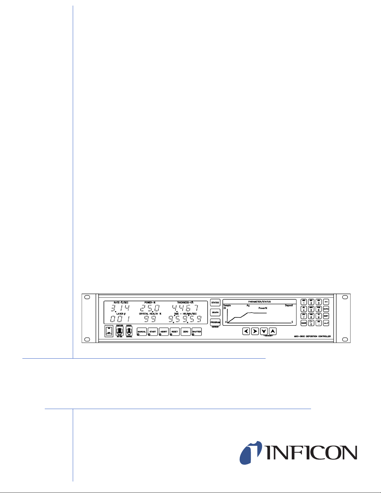
MDC-360C
Film Deposition Controller
IPN 624800 Rev. F
Page 2

Page 3

OPERATION and SERVICE MANUAL
MDC-360C
Film Deposition Controller
IPN 624800 Rev. F
®
www.inficon.com reachus@inficon.com
Due to our continuing program of product improvements, specifications are subject to change without notice.
©2007 INFICON
Page 4

Trademarks
The trademarks of the products mentioned in this manual are held by the companies that
produce them.
INFICON® is a trademark of INFICON Inc.
All other brand and product names are trademarks or registered trademarks of their respective companies.
Disclaimer
The information contained in this manual is believed to be accurate and reliable. However, INFICON assumes
no responsibility for its use and shall not be liable for any special, incidental, or consequential damages related
to the use of this product.
Disclosure
The disclosure of this information is to assist owners of INFICON equipment to properly operate and maintain
their equipment, and does not constitute the release of rights thereof. Reproduction of this information and
equipment described herein is prohibited without prior written consent from INFICON, Two Technology Place,
East Syracuse, NY 13057-9714. Phone 315.434.1100. See www.inficon.com.
Copyright
©2004 All rights reserved.
Reproduction or adaptation of any part of this document without permission is unlawful.
January 2004, Revision A.
August 2004, Revision B.
June 2005, Revision C.
October 2005, Revision D.
October 2006, Revision E.
November 2007, Revision F
General Safety Warning
WARNING
All standard safety procedures associated with the safe
handling of electrical equipment must be observed. Always
disconnect power when working inside the controller. Only
properly trained personnel should attempt to service the
instrument.
Page 5

DECLARATION
OF
CONFORMITY
This is to certify that this equipment, designed and manufactured by:
INFICON Inc.
Two Technology Place
East Syracuse, NY 13057
USA
meets the essential safety requirements of the European Union and is placed on the market accordingly. It
has been constructed in accordance with good engineering practice in safety matters in force in the
Community and does not endanger the safety of persons, domestic animals or property when properly
installed and maintained and used in applications for which it was made.
Equipment Description: MDC-360C Thin Film Deposition Controllers, including the SO-100
Oscillator Package.
Applicable Directives: 73/23/EEC as amended by 93/68/EEC (LVD)
89/336/EEC as amended by 93/68/EEC (EMC)
2002/95/EC (RoHS)
Applicable Standards: EN 61010-1:2001 (Safety)
EN 61326-1:1997/A1:1998/A2:2001, Class A: Emissions per Table 3
Immunity per Table A.1
Due to the classification of this product it is currently exempt from the RoHS
directive.
CE Implementation Date: November 1, 2007
Authorized Representative: Duane H. Wright
Quality Assurance Manager, ISS
INFICON Inc.
ANY QUESTIONS RELATIVE TO THIS DECLARATION OR TO THE SAFETY OF INFICON'S PRODUCTS SHOULD BE DIRECTED,
IN WRITING, TO THE QUALITY ASSURANCE DEPARTMENT AT THE ABOVE ADDRESS.
10/01/07
Page 6

Page 7

Warranty
INFICON warrants the product to be free of functional defects in material and
workmanship and that it will perform in accordance with its published specification
for a period of (twenty-four) 24 months.
The foregoing warranty is subject to the condition that the product be properly
operated in accordance with instructions provided by INFICON or has not been
subjected to improper installation or abuse, misuse, negligence, accident,
corrosion, or damage during shipment.
Purchaser's sole and exclusive remedy under the above warranty is limited to, at
INFICON's option, repair or replacement of defective equipment or return to
purchaser of the original purchase price. Transportation charges must be prepaid
and upon examination by INFICON the equipment must be found not to comply
with the above warranty. In the event that INFICON elects to refund the purchase
price, the equipment shall be the property of INFICON.
This warranty is in lieu of all other warranties, expressed or implied and
constitutes fulfillment of all of INFICON's liabilities to the purchaser. INFICON
does not warrant that the product can be used for any particular purpose other
than that covered by the applicable specifications. INFICON assumes no liability in
any event, for consequential damages, for anticipated or lost profits, incidental
damage of loss of time or other losses incurred by the purchaser or third party in
connection with products covered by this warranty or otherwise.
www.inficon.com reachus@inficon.com
Page 8

Page 9
SAFETY PRECAUTION AND PREPARATION FOR USE
Input Power Requirements
The MDC-360C Deposition Controller can be set to operate one of the following
line voltages: 100, 120, 200, or 240 VAC at line frequency of 50 or 60 Hz.
Maximum power consumption is 25 watts. See Section 8.3.2 for instruction on
selecting line voltage.
Power Entry Module
The AC (alternating current) power entry module, located in the rear panel of the
MDC-360C, provides connection to the power source and a protective ground. It
also holds the fuses and the voltage selection wheel.
Power Cord
WARNING: To avoid electrical shock, always connect the power cord to an
AC outlet which has a proper protective ground.
The MDC-360C comes with a detachable, three-wire power cord for connection
to a power source with protective ground.
The MDC-360C chassis is connected to the power ground to protect against
electrical shock. Always connect to an AC outlet which has a properly connected
protective ground. If necessary, or when in doubt, consult a certified electrician.
Grounding
A grounding lug is located on the rear panel, near the power entry module. Use
heavy ground wire, wire braid, or copper strap of #12 AWG or larger to connect
this grounding lug directly to a facility protective earth ground to provide
additional protection against electrical shock. Refer to Section 8.2 and Figure
8-11 for details.
Line Fuses
There are two 5 x 20 mm fuses mounted inside the power entry module. They are
accessible via the snap-in cover. Replace with the correct fuse rating: IEC T Type
(Slow), 4/10 A, 250 VAC. Refer to Section 8.3.2 for instruction to replace the
fuse.
Power Switch
WARNING: Do NOT use the power switch as a disconnecting device;
disconnect the power cord from the power entry module to fully remove
hazardous voltage from inside the MDC-360C.
The power switch is located on the front lower left of the MDC-360C. Toggle the
switch to
when the LCD and all of the LEDs are off. However, turning the power switch
off does not fully remove the AC power from inside the unit. Always disconnect
the power cord from the power entry module to fully remove AC power from
inside the unit.
I to turn the controller on, or to O to turn it off. The MDC-360C is off
iv
Page 10
SAFETY TERMS AND SYMBOLS
Terms Used in This Manual
WARNING. Warning statements identify conditions or practices that could
result in personnel injuries or loss of life.
CAUTION. Caution statements identify conditions or practices that could
result in damage to the MDC-360C or other property.
NOTE. Note statements identify a sensitive or irreversible procedure. Proceed
with caution.
Terms Used on the MDC-360C
DANGER indicates and injury hazard immediately accessible as you read the
marking.
WARNING indicates an injury hazard not immediately accessible as you read the
marking.
CAUTION indicates a hazard to the MDC-360C or other property.
Symbols Used on the Product and in the Manual
DANGER
Hazardous Voltage
FUSE
Refer to Manual for
Instruction
ATTENTION
Refer to Manual
Protective Ground
AC
Alternating Current
v
Page 11

Table of Contents
SAFETY PRECAUTION AND PREPARATION FOR USE...................................................IV
SAFETY TERMS AND SYMBOLS.............................................................................................V
1. GENERAL DESCRIPTION.............................................................................................1-1
1.1 PURPOSE....................................................................................................................... 1-1
1.2 FEATURES ....................................................................................................................1-1
1.2.1 MULTI-CRYSTAL AVERAGING ............................................................................... 1-1
1.2.2 EXTENSIVE PROGRAM STORAGE .........................................................................1-1
1.2.3 DYNAMIC MEASUREMENT UPDATE RATE..........................................................1-1
1.2.4 SUPERIOR COLOR GRAPHICS DISPLAY .............................................................. 1-1
1.2.5 PROGRAM SECURITY.............................................................................................. 1-1
1.2.6 DESIGNED FOR UNATTENDED OPERATION ...................................................... 1-1
1.2.7 FAIL SAFE ABORTS.................................................................................................. 1-2
1.2.8 ABOR T STATUS RETENTION .................................................................................. 1-2
1.2.9 RUN COMPLETION ON CRYSTAL FAILURE......................................................... 1-2
1.2.10 POWERFU L SYSTEM INTERFACE..................................................................... 1-2
1.2.11 POWER SUPPLY NOISE TOLERANCE............................................................... 1-2
1.2.12 INTERNATIONAL STANDARD POWER CONNECTOR ..................................... 1-2
1.2.13 FIELD UP GRADABLE ......................................................................................... 1-2
1.3 SPECIFICATIONS......................................................................................................... 1-3
1.3.1 MEASUREMENT ....................................................................................................... 1-3
1.3.2 DISPLAY .................................................................................................................... 1-3
1.3.3 COMMUNICATION................................................................................................... 1-3
1.3.4 PROGRAM STORAGE CAPACITY ...........................................................................1-3
1.3.5 PROCESS PARAMETERS ......................................................................................... 1-3
1.3.6 MATER IAL P ARAMETERS ....................................................................................... 1-4
1.3.7 INPUT/OUTPUT CAPABILITY.................................................................................1-5
1.3.8 SENSOR PARAMETERS............................................................................................ 1-5
1.3.9 SOURCE PARAMETERS........................................................................................... 1-6
1.3.10 RECORDER P ARAMETERS................................................................................. 1-6
1.3.11 UTILITY SETUP PARAMETER ............................................................................ 1-6
1.3.12 OTHER..................................................................................................................1-6
1.4 ACCESSORIES.............................................................................................................. 1-7
vi
2. FRONT PANEL DISPLAYS AND CONTROLS...........................................................2-1
2.1 OPERATING DISPLAYS.............................................................................................. 2-1
2.1.1 RATE.......................................................................................................................... 2-1
2.1.2 POWER...................................................................................................................... 2-1
2.1.3 THICKNESS............................................................................................................... 2-1
2.1.4 LAYER NUMBER....................................................................................................... 2-1
2.1.5 CRYST AL HEALTH % ............................................................................................... 2-1
2.1.6 TIME DISPLAY.......................................................................................................... 2-2
2.2 PARAMETER/STATUS DISPLAYS ............................................................................ 2-2
2.3 OPERATING CONTROLS............................................................................................ 2-2
2.3.1 MANUAL KEY ........................................................................................................... 2-2
2.3.2 START KEY................................................................................................................ 2-3
2.3.3 ABORT KEY...............................................................................................................2-3
2.3.4 RESET KEY................................................................................................................ 2-3
2.3.5 ZERO KEY.................................................................................................................2-3
2.3.6 SHUTTER KEY ..........................................................................................................2-3
2.3.7 STATUS KEY.............................................................................................................. 2-3
2.3.8 GRAPH KEY ..............................................................................................................2-3
2.3.9 ARROW KEYS............................................................................................................ 2-4
Page 12

PROGRAM KEY.................................................................................................... 2-4
2.3.10
2.3.11 ALPHANUMERIC KEYBOARD ........................................................................... 2-5
3. BENCH CHECKOUT & INSPECTION......................................................................... 3-1
3.1 INSPECTION................................................................................................................. 3-1
3.2 INITIAL POWER UP..................................................................................................... 3-1
3.3 SAMPLE PROGRAM.................................................................................................... 3-1
3.3.1 MATERIAL #1 PARAMETERS .................................................................................. 3-2
3.3.2 MATERIAL #2 PARAMETERS .................................................................................. 3-3
3.3.3 PROCESS PARAMETERS......................................................................................... 3-4
3.4 SIMULATE OPERATION............................................................................................. 3-4
3.5 MANUAL OPERATION ............................................................................................... 3-4
3.6 INSTALLING OPTION BOARDS................................................................................ 3-4
3.6.1 SOURCE-SENSOR BOARD ...................................................................................... 3-5
3.6.2 DISCRETE I/O BOARD............................................................................................. 3-5
3.6.3 IEEE -488 OPTION BOARD...................................................................................... 3-5
3.7 DIGITAL TO ANALOG CONVERTER (DAC) CHECKOUT...................................... 3-5
4. PROGRAMMING AND CONTROLLER SETUP........................................................ 4-1
4.1 GENERAL...................................................................................................................... 4-1
4.1.1 NAVIGATING THE MENU STRUCTURE ................................................................ 4-1
4.1.2 ENTERING ALPHA CHARACTERS.......................................................................... 4-1
4.1.3 ENTERING TIME PARAMETERS............................................................................. 4-2
4.1.4 COPYING AND DELETING ..................................................................................... 4-2
4.1.5 PASSWORD PROTECTION...................................................................................... 4-2
4.1.5.1 VIEW/RUN PROCESS PASSWORD ...........................................................................4-3
4.1.5.2 EDIT PROCESS PASSWORD ...................................................................................... 4-3
4.1.5.3 EDIT MATERIAL PASSWORD................................................................................... 4-3
4.1.6 ADJUSTING PARAMETER/STATUS DISPLAY CONTRAST ................................... 4-3
4.2 GETTING STARTED.................................................................................................... 4-3
4.2.1 UTIL I TY SET UP........................................................................................................ 4-4
4.2.2 DAC SET UP.............................................................................................................. 4-4
4.2.3 SOURCE SETUP ....................................................................................................... 4-4
4.2.4 SENSOR SETUP........................................................................................................ 4-7
4.2.4.1 EXAMPLE USING INFICON’S RSH-600 SIX CRYSTAL SENSOR HEAD ............ 4-9
4.2.5 INPUT , OU TPUT AND ACTION SETUP.................................................................. 4-9
4.2.6 DISPLAY SETUP......................................................................................................4-10
4.2.7 MATER IAL SETUP...................................................................................................4-11
4.2.7.1 POWER RAMPS..........................................................................................................4-11
4.2.7.2 AUTOMATIC CRYSTAL SWITCHING.................................................................... 4-12
4.2.7.3 RATE ESTABLISH..................................................................................................... 4-12
4.2.7.4 RATE RAMPS............................................................................................................. 4-12
4.2.7.5 RATE SAMPLE MODE.............................................................................................. 4-13
4.2.7.6 RATE DEVIATION ALARM......................................................................................4-13
4.2.8 PROCESS SETUP.....................................................................................................4-13
4.2.9 STARTING A NEW PROCESS..................................................................................4-13
4.2.10 RESUMING A PROCESS FROM ABORT OR HALT..........................................4-14
4.3 DETAILED PROGRAMMING ....................................................................................4-14
4.3.1 VIEW/EDIT PROCESS.............................................................................................4-14
4.3.1.1 DEFINE A PROCESS..................................................................................................4-14
4.3.2 VIEW/EDIT MATERIAL ...........................................................................................4-16
4.3.2.1 DEFINE A MATERIAL...............................................................................................4-17
4.3.3 SYSTEM SETUP .......................................................................................................4-25
4.3.3.1 EDIT DISPLAY SETUP .............................................................................................. 4-25
4.3.3.2 PROGRAM INPUTS...................................................................................................4-27
4.3.3.3 PROGRAM OUTPUTS................................................................................................4-28
4.3.3.4 PROGRAM ACTIONS................................................................................................4-34
4.3.3.5 EDIT SENSOR SETUP................................................................................................4-36
4.3.3.6 EDIT SOURCE SETUP............................................................................................... 4-39
4.3.3.7 EDIT DAC SETUP......................................................................................................4-42
vii
Page 13

4.3.3.8 EDIT UTILITY SETUP............................................................................................... 4-42
5. OPERATING THE MDC-360C....................................................................................... 5-1
5.1 SIGN-ON SCREEN........................................................................................................5-1
5.2 STARTING A NEW PROCESS..................................................................................... 5-1
5.3 STARTING A NEW LAYER......................................................................................... 5-2
5.4 RESUMING AN ABORTED OR HALTED PROCESS.................................................5-2
5.5 GRAPH DISPLAYS........................................................................................................5-3
5.6 STATUS DISPLAYS......................................................................................................5-4
5.7 VIEWING RESULTS..................................................................................................... 5-5
5.8 MODES ..........................................................................................................................5-7
5.8.1 PROCESS READY...................................................................................................... 5-7
5.8.2 ABORT .......................................................................................................................5-7
5.8.3 HALT (SOFT ABORT) ............................................................................................... 5-8
5.8.4 IN PROCESS.............................................................................................................. 5-8
5.8.5 NOT SAMP LI NG........................................................................................................5-8
5.8.6 PROCESS COMPLETE .............................................................................................5-8
5.8.7 MANUAL....................................................................................................................5-8
5.8.8 SIMULATE................................................................................................................. 5-8
5.9 STATES..........................................................................................................................5-8
5.10 TROUBLE, ERROR AND WARNING MESSAGES.................................................... 5-8
5.10.1 DESCRIPTION......................................................................................................5-9
5.10.1.1 MIN RATE&MAX POWER........................................................................................ 5-10
5.10.1.2 MAX RATE&MIN POWER........................................................................................ 5-10
5.10.1.3 SYSTEM SETUP MEMORY CORRUPTED.............................................................. 5-10
5.10.1.4 PROCESS MEMORY CORRUPTED ......................................................................... 5-10
5.10.1.5 MATERIAL MEMORY CORRUPTED...................................................................... 5-10
5.10.1.6 RATE EST. ERROR.................................................................................................... 5-10
5.10.1.7 CRYSTAL FAILURE.................................................................................................. 5-10
5.10.1.8 SOURCE FAULT ........................................................................................................ 5-10
5.10.1.9 SENSOR FAULT......................................................................................................... 5-11
5.10.1.10 NO SENSORS ENABLED .......................................................................................... 5-11
5.10.1.11 TIME POWER............................................................................................................. 5-11
5.10.1.12 RATE DEV. ALARM.................................................................................................. 5-11
5.10.1.13 ALARM ACTION....................................................................................................... 5-11
5.10.1.14 CRYSTAL MARGINAL............................................................................................. 5-11
5.10.1.15 RATE DEV. ALERT................................................................................................... 5-11
5.10.1.16 MAX POWER ALERT................................................................................................ 5-11
5.10.1.17 MIN POWER ALERT................................................................................................. 5-11
5.10.1.18 ALERT ACTION......................................................................................................... 5-11
5.10.1.19 XTAL FAIL SWITCH................................................................................................. 5-12
5.10.1.20 XTAL MRGN SWITCH.............................................................................................. 5-12
5.10.1.21 RATE DEV. ATTEN................................................................................................... 5-12
5.10.1.22 MAXIMUM POWER.................................................................................................. 5-12
5.10.1.23 MINIMUM POWER.................................................................................................... 5-12
5.10.1.24 CHANGE POCKET..................................................................................................... 5-12
5.10.1.25 CHANGE CRYSTAL.................................................................................................. 5-12
5.10.1.26 ATTENTION ACTION............................................................................................... 5-12
5.10.1.27 CALIBRATION DONE............................................................................................... 5-12
viii
6. TUNING THE MDC-360C CONTROL LOOP.............................................................. 6-1
6.1 CONTROL LOOP BASICS................................................................................................... 6-1
6.2 CONTROL LOOPS APPLIED TO VACUUM DEPOSITION....................................................... 6-2
6.3 ESTABLISHING MDC-360C CONTROL LOOP PARAMETERS ............................................. 6-3
7. INPUT/OUTPUT CHARACTERISTICS........................................................................7-1
7.1 SOURCE CONTROL VOLTAGE OUTPUT.................................................................7-1
7.2 SENSOR INPUT............................................................................................................. 7-1
7.3 DISCRETE OUTPUTS................................................................................................... 7-1
Page 14

7.4
DISCRETE INPUTS ...................................................................................................... 7-1
7.5 DIGITAL-TO-ANALOG CONVERTER OUTPUTS.................................................... 7-2
7.6 DIGITAL-TO-ANALOG CONVERTER CONTROL INPUTS .................................... 7-2
8. CONTROLLER INSTALLATION................................................................................. 8-1
8.1 MOUNTING .................................................................................................................. 8-1
8.2 PROPER GROUNDING................................................................................................ 8-1
8.3 EXTERNAL CONNECTIONS ...................................................................................... 8-1
8.3.1 POWER...................................................................................................................... 8-1
8.3.2 LINE VOLTAGE SELECTION AND FUSE REPLACEMENT .................................. 8-2
8.3.3 GROUND LUG.......................................................................................................... 8-2
8.3.4 REMOTE POWER HANDSET................................................................................... 8-3
8.3.5 SOURCE-SENSOR .................................................................................................... 8-3
8.3.6 RS-232 COMMUNICATION...................................................................................... 8-3
8.3.7 DISCRETE INPUT/OUTPUT.................................................................................... 8-3
8.3.8 DIGITAL-TO-ANALOG CONVERTER (DAC).......................................................... 8-4
8.4 POWER SWITCH ............................................................................................................... 8-4
8.5 CONTROLLER COVER REMOVAL........................................................................... 8-4
9. SYSTEM INSTALLATION............................................................................................. 9-1
9.1 SENSOR HEAD DESCRIPTION .................................................................................. 9-1
9.2 SENSOR HEAD INSTALLATION............................................................................... 9-1
9.3 SENSOR OSCILLATOR ............................................................................................... 9-2
9.3.1 INSTALLATION......................................................................................................... 9-2
9.4 INSTRUMENTATION FEEDTHROUGH.................................................................... 9-2
9.5 SENSOR CRYSTAL REPLACEMENT........................................................................ 9-2
9.5.1 CRYSTAL CARE AND HANDLING........................................................................... 9-3
9.5.2 CRYSTAL REPLACEMENT PROCEDURE .............................................................. 9-3
9.6 TYPICAL SYSTEM INSTALLATION......................................................................... 9-5
10. THEORY OF OPERATION......................................................................................10-1
10.1 BASIC MEASUREMENT ............................................................................................10-1
10.2 FILM THICKNESS CALCULATION..........................................................................10-1
10.3 CRYSTAL HEALTH CALCULATION.......................................................................10-3
10.4 RATE CALCULATION................................................................................................10-3
10.5 MULTI-SENSOR AVERAGING ...........................................................................................10-4
10.6 EMPIRICAL CALIBRATION......................................................................................10-5
10.6.1 FILM DENSITY....................................................................................................10-5
10.6.2 TOOLING FACTOR.............................................................................................10-5
10.6.3 ACOUSTIC IMPEDANCE...................................................................................10-6
11. COMPUTER INTERFACE........................................................................................11-1
11.1 GENERAL.....................................................................................................................11-1
11.2 RS-232 SERIAL INTERFACE......................................................................................11-1
11.3 RS-485 SERIAL INTERFACE......................................................................................11-1
11.4 IEEE-488 PARALLEL INTERFACE............................................................................11-2
11.5 PROTOCOL..................................................................................................................11-2
11.6 DATA TYPES...............................................................................................................11-3
11.7 MESSAGE RECEIVED STATUS ................................................................................11-3
11.8 INSTRUCTION SUMMARY .......................................................................................11-4
11.9 INSTRUCTION DESCRIPTIONS................................................................................11-5
12. REPAIR AND MAINTENANCE...............................................................................12-1
12.1 HANDLING PRECAUTIONS......................................................................................12-1
12.2 MAINTENANCE PHILOSOPHY.................................................................................12-1
12.3 TROUBLE SHOOTING AIDS......................................................................................12-2
12.4 RETURNING THE MDC-360C TO THE FACTORY..................................................12-3
ix
Page 15

13.
APPENDIX A – MATING CABLE COLOR CODES ............................................13-1
14. APPENDIX B – PARAMETER TEMPLATES....................................................... 14-1
14.1 MATERIAL.................................................................................................................. 14-2
14.2 PROCESS..................................................................................................................... 14-4
14.3 DISPLAY SETUP......................................................................................................... 14-5
14.4 INPUTS ........................................................................................................................ 14-6
14.5 OUTPUTS.....................................................................................................................14-7
14.6 ACTIONS..................................................................................................................... 14-8
14.7 SENSOR SETUP.......................................................................................................... 14-9
14.8 SOURCE SETUP..........................................................................................................14-9
14.9 DAC SETUP............................................................................................................... 14-10
14.10 UTILITY SETUP........................................................................................................ 14-10
15. INDEX..............................................................................................................................11
16. MENU MAPS.............................................................................................................. 16-1
x
Page 16

Table of Figures
FIGURE 2-1 OPERATING DISPLAY........................ERROR! BOOKMARK NOT DEFINED.
FIGURE 2-2 PARAMETER/STATUS DISPLAY...................................................................... 2-2
FIGURE 2-3 PROGRAMMING SECTION................................................................................. 2-4
FIGURE 2-4 ARROW KEYS....................................................................................................... 2-4
FIGURE 2-5 ALPHANUMERIC KEYBOARD.......................................................................... 2-5
FIGURE 3-1 REMOTE POWER HANDSET............................................................................. 3-7
FIGURE 4-1 THE MAIN MENU................................................................................................ 4-1
FIGURE 4-2 SELECT PROCESS SCREEN..............................................................................4-14
FIGURE 4-3 DEFINE PROCESS SCREEN..............................................................................4-14
FIGURE 4-4 SELECT LAYER MATERIAL SCREEN.............................................................4-16
FIGURE 4-5 SELECT MATERIAL SCREEN............................................................................4-16
FIGURE 4-6 DEFINE MATERIAL SCREEN............................................................................4-17
FIGURE 4-7 SYSTEM SETUP MENU SCREEN.....................................................................4-25
FIGURE 4-8 DISPLAY SETUP SCREEN.................................................................................4-25
FIGURE 4-9 PROGRAM INPUT SCREEN...............................................................................4-28
FIGURE 4-10 SELECT OUTPUT SCREEN .............................................................................4-29
FIGURE 4-11 PROGRAM OUTPUT SCREEN ........................................................................4-29
FIGURE 4-12 OUTPUT CONDITIONS SELECTION SCREEN..............................................4-30
FIGURE 4-13 OUTPUT CONDITIONS SELECTION - SUB MENU.......................................4-31
FIGURE 4-14 ACTION SELECTION SCREEN........................................................................4-34
FIGURE 4-15 PROGRAM ACTION SCREEN..........................................................................4-34
FIGURE 4-16 SELECT DEFINED ACTION SCREEN.............................................................4-35
FIGURE 4-17 SENSOR SETUP SCREEN................................................................................4-36
FIGURE 4-18 SOURCE SETUP SCREEN................................................................................4-39
FIGURE 4-19 DAC SETUP SCREEN.......................................................................................4-42
FIGURE 4-20 UTILITY SETUP SCREEN................................................................................4-43
FIGURE 5-1 SIGN-ON SCREEN............................................................................................... 5-1
FIGURE 5-2 RUN PROCESS SELECTION SCREEN .............................................................. 5-2
FIGURE 5-3 RATE VS. TIME GRAPH..................................................................................... 5-3
FIGURE 5-4 RATE DEVIATION VS. TIME GRAPH .............................................................. 5-3
FIGURE 5-5 THICKNESS VS. TIME GRAPH.......................................................................... 5-3
FIGURE 5-6 POWER VS. TIME GRAPH.................................................................................. 5-4
FIGURE 5-7 SOURCE/SENSOR STATUS SCREEN................................................................ 5-4
FIGURE 5-8 I/O STATUS SCREEN.......................................................................................... 5-5
FIGURE 5-9 VIEW RESULTS SCREEN................................................................................... 5-6
FIGURE 5-10 RATE VS. TIME PROCESS LOG GRAPH........................................................ 5-7
FIGURE 5-11 TYPICAL PROCESS PROFILE.........................................................................5-13
FIGURE 7-1 PASSIVE INPUT BUFFER CIRCUIT.................................................................. 7-3
FIGURE 7-2 ACTIVE INPUT BUFFER CIRCUIT..................................................................... 7-4
FIGURE 7-3 DAC OUTPUT CIRCUIT...................................................................................... 7-5
FIGURE 7-4 SENSOR INPUT BUFFER CIRCUIT.................................................................. 7-6
FIGURE 7-5 SOURCE OUTPUT DRIVER CIRCUIT............................................................... 7-7
FIGURE 8-1 POWER ENTRY MODULE................................................................................... 8-2
FIGURE 8-2 MDC-360C FRONT PANEL................................................................................. 8-6
FIGURE 8-3 MDC-360C REAR PANEL ................................................................................... 8-7
FIGURE 8-4 DAC SOCKET CONNECTOR PIN OUT ............................................................. 8-8
FIGURE 8-5 SOURCE SOCKET CONNECTOR PIN OUT...................................................... 8-8
FIGURE 8-6 D9S DTE REAR-PANEL RS-232 SOCKET CONNECTOR................................ 8-9
FIGURE 8-7 D37P DISCRETE I/O PLUG CONNECTOR........................................................8-10
FIGURE 8-8 RJ11 FRONT PANEL RS-232 CONNECTOR ....................................................8-11
FIGURE 8-9 FRONT PANEL MANUAL POWER CONNECTOR.........................................8-11
FIGURE 8-10 MDC-360C TOP VIEW (COVER REMOVED)................................................8-12
FIGURE 8-11 RECOMMENDED GROUNDING METHOD....................................................8-13
FIGURE 9-1 REMOVING THE CRYSTAL RETAINER........................................................... 9-4
FIGURE 9-2 INSTALLING THE SENSOR CRYSTAL............................................................. 9-4
xi
Page 17

FIGURE 9-3 SENSOR OSCILLATOR SCHEMATIC............................................................... 9-6
FIGURE 9-4 SENSOR OSCILLATOR OUTLINE.....................................................................9-7
FIGURE 9-5 IF-111 INSTRUMENTATION FEEDTHROUGH OUTLINE.............................. 9-8
FIGURE 9-6 SH-102 SENSOR HEAD OUTLINE .....................................................................9-9
FIGURE 9-7 TYPICAL SYSTEM INSTALLATION............................................................... 9-10
FIGURE 13-1 PLUG PIN OUT - SOURCE CABLE CONNECTOR........................................ 13-1
FIGURE 13-2 PLUG PIN OUT - DAC CABLE CONNECTOR...............................................13-2
FIGURE 16-1 MAP OF STATUS AND GRAPH SCREENS....................................................16-1
FIGURE 16-2 MAP OF PROGRAMMING MENU SCREENS................................................ 16-2
xii
Page 18

List of Tables
TABLE 4-1TABLE OF INPUT STATES FOR BCD FEEDBACK TYPE.................................4-38
TABLE 4-2 TABLE OF INPUT STATES FOR BCD FEEDBACK TYPE................................4-41
TABLE 5-1 TROUBLE CONDITIONS AND WARNINGS...................................................... 5-9
TABLE 6-1 DEFAULT AND RANGE FOR PID PARAMETERS............................................. 6-3
TABLE 6-2 SUGGESTED PID STARTING VALUES FOR DIFFERENT SOURCES............. 6-3
TABLE 8-1 DAC SYSTEM INTERFACE CONNECTOR PIN ASSIGNMENTS.................... 8-8
TABLE 8-2 SOURCE CONTROL SYSTEM INTERFACE CONNECTOR PIN
ASSIGNMENTS................................................................................................................. 8-8
TABLE 8-3 D9 REAR PANEL RS-232/RS-485 CONNECTOR PIN ASSIGNMENTS ........... 8-9
TABLE 8-4 DISCRETE I/O SYSTEM INTERFACE CONNECTOR PIN ASSIGNMENTS..8-10
TABLE 8-5 RJ11 FRONT PANEL RS-232 CONNECTOR PIN ASSIGNMENTS..................8-11
TABLE 8-6 FRONT PANEL MANUAL POWER CONNECTOR PIN ASSIGNMENTS.......8-11
TABLE 10-1 MATERIAL DENSITY AND ACOUSTIC IMPEDANCE VALUE....................10-7
TABLE 13-1 SOURCE CONTROL CABLE COLOR CODE - (4 PIN MINI DIN) ...............13-1
TABLE 13-2 DAC CABLE COLOR CODE - (7 PIN MINI DIN).........................................13-2
xiii
Page 19

MDC-360C DEPOSITION CONTROLLER
1. GENERAL DESCRIPTION
1.1 PURPOSE
The MDC-360C is a full-featured deposition controller which can provide
automatic control of single or multi-layer film deposition in either a production or
development environment. The MDC-360C will improved predictability and
repeatability of deposited film characteristics through dependable digital control
and multi-sensor averaging.
The MDC-360C makes programming and operation easy with large LED displays
for important run-time values, a graphic LCD display for graphs of rate, rate
deviation, thickness and deposit power, an easy to use menu-driven user interface
providing unparalleled access to plain English programming of processes,
materials, inputs and outputs.
1.2 FEATURES
The MDC-360C incorporates numerous features which are economically
justifiable as a result of rapid advances in semiconductor technology and the
advent of low cost microprocessors.
1.2.1 MULTI-CRYSTAL AVERAGING
The MDC-360C provides greater accuracy in thin film deposition by averaging up
to six sensors distributed throughout the chamber to account for changes in vapor
distribution during deposition.
1.2.2 EXTENSIVE PROGRAM STORAGE
The MDC-360C is capable of storing up to 99 processes, 999 layer definitions and
32 complete material definitions. Once a program is entered it will be maintained
in memory for a minimum of 5 years without external power.
1.2.3 DYNAMIC MEASUREMENT UPDATE RATE
Measurement is dynamically adjusted from 0.5 to 10 Hz for optimum resolution
and control.
1.2.4 SUPERIOR COLOR GRAPHICS DISPLAY
The MDC-360C features a 240x64 pixel color LCD graphics display allowing
real time graphing of important process information such as rate, rate deviation,
thickness and power.
1.2.5 PROGRAM SECURITY
To assure the integrity of stored programs, the MDC-360C incorporates edit
passwords to guard against unauthorized program changes.
1.2.6 DESIGNED FOR UNATTENDED OPERATION
The MDC-360C has been designed for truly automatic operation and toward this
end incorporates extensive internal monitoring and overriding abort circuitry to
GENERAL DESCRIPTION 1-1
Page 20

MDC-360C DEPOSITION CONTROLLER
minimize the possibility of damage in the event of a failure or other problem in
the total deposition system. In addition there are attention, alert and alarm signals
with adjustable volume for trouble and routine operator call.
1.2.7 FAIL SAFE ABORTS
In the event of an MDC-360C failure, as evidenced by unsatisfactory internal
checks, the MDC-360C will abort the process and shut off all outputs. In addition
to the internal checks, the MDC-360C also provides user enabled aborts on
excessive rate control error or crystal failure.
1.2.8 ABORT STATUS RETENTION
In the event that the MDC-360C does abort during the deposition process,
pertinent information is stored at the time of abort. More importantly, the process
can be easily resumed once the problem is corrected without re-programming.
1.2.9 RUN COMPLETION ON CRYSTAL FAILURE
The extensive monitoring and abort functions are designed to protect the system
and/or process from serious and hopefully infrequent malfunctions of the
deposition system. A condition which need not cause an abort is the condition of
crystal failure. The MDC-360C can be set to abort upon crystal failure or run to
completion using a backup crystal or time/power method.
1.2.10 POWERFUL SYSTEM INTERFACE
Fully programmable discrete inputs and outputs permit the MDC-360C to be
easily interfaced into deposition systems controlling the most complex processes.
Also, source control outputs are fully isolated avoiding ground loop problems.
The MDC-360C also supports input from an optical monitor for optical
termination of film thickness.
1.2.11 POWER SUPPLY NOISE TOLERANCE
Integral RFI filter and large energy storage capacitors will tolerate high levels of
power supply noise and power interruptions of 700 ms or less without effect.
1.2.12 INTERNATIONAL STANDARD POWER CONNECTOR
The power connector is internationally approved and meets IEC (International
Electrotechnical Commission) standards. It allows selection of input power
voltages ranging from 100 to 240 volts at a frequency of 50 or 60 Hz and includes
an integral RFI filter.
1.2.13 FIELD UPGRADABLE
Plug-in interface boards and option boards allow the basic unit to be upgraded in
the field to the maximum system level.
GENERAL DESCRIPTION 1-2
Page 21
MDC-360C DEPOSITION CONTROLLER
1.3 SPECIFICATIONS
1.3.1 MEASUREMENT
Frequency Resolution 0.03 Hz @ 6.0 MHz
Mass Resolution 0.375 ng/cm2
Thickness Accuracy 0.5% + 1 count
Measurement Update Rate Dynamically adjusted, 0.5 to 10 Hz
Display Update Rate 10 Hz
Sensor Crystal Frequency 2.5, 3, 5, 6, 9, 10 MHz
1.3.2 DISPLAY
Thickness Display Autoranging: 0.000 to 999.9 KÅ
Rate Display Autoranging: 0.0 to 999 Å/sec
Power Display 0.0 to 99.9%
Time Display 0 to 9:59:59 H:MM:SS
Crystal Health % 0 to 99%
Layer Number 1 to 999
Graphics Display 240X64 LCD with CCFL
backlighting
1.3.3 COMMUNICATION
RS-232 serial port standard
RS-485 serial port optional
IEEE-488 bus interface optional
1.3.4 PROGRAM STORAGE CAPACITY
Process 99, user definable
Layer 999, user definable
Material 32, user definable
1.3.5 PROCESS PARAMETERS
Process Name 12 character string
Edit password 4 character string
Run/View password 4 character string
Layer# 1 to 999 Material name, Thickness
GENERAL DESCRIPTION 1-3
Page 22

MDC-360C DEPOSITION CONTROLLER
1.3.6 MATERIAL PARAMETERS
Material Name 10 character string
Source # 1 to 6
Pocket # 1 to 16
Material Density 0.80 to 99.9 gm/cm3
Acoustic Impedance 0.50 to 59.9 gm/cm2 sec
Tooling Factor 10.0 to 499.9%
Proportional Gain 0.00 to 9999
Integral Time Constant 0 to 99.9 sec
Derivative Time Constant 0 to 99.9 sec
Rise to Soak Time 0 to 9:59:59 H:MM:SS
Soak Power 0 to 99%
Soak Time 0 to 9:59:59
Rise to Predeposit Time 0 to 9:59:59
Predeposit Power 0 to 99.9%
Predeposit Time 0 to 9:59:59
Rate Establish Time 0 to 60 sec
Rate Establish Error 0 to 99.9%
Deposition Rate (1 to 5) 00.0 to 999.9 Å/sec
Rate Start Thickness (1 to 4) 0 to 100%
Rate Stop Thickness (1 to 4) 0 to 100%
Time Setpoint 0 to 9:59:59
Ramp to Feed Time 0 to 9:59:59
Feed Power 0 to 99.9%
Feed Time 0 to 9:59:59
Ramp to Idle Time 0 to 9:59:59
Idle Power 0 to 99.9%
Maximum Power 0 to 99.9%
Power Alarm Delay 0 to 99 sec
Minimum Power 0 to 99.9%
Rate Deviation Attention 0 to 99.9%
Rate Deviation Alarm 0 to 99.9%
Rate Deviation Abort 0 to 99.9%
Sample Dwell % 0 to 100.0%
Sample Period 0:01:00 to 9:59:59
Sensor (1 to 6) Fail NotUsed, Disable, HaltLast, Halt,
TimePower, Switch
Sensor (1 to 6) Tooling 10.0 to 499.9%
Sensor (1 to 6) Weight 10.0 to 499.9%
Sensor (1 to 6) Crystal # 1 to 8
Sensor (1 to 6) Backup Sensor # 1 to 6
Sensor (1 to 6) Backup Crystal # 1 to 8
Material Password 4 character string
GENERAL DESCRIPTION 1-4
Page 23

MDC-360C DEPOSITION CONTROLLER
The MDC-360C also has a built in material library that contains many common
material names along with their density and acoustic impedance values.
1.3.7 INPUT/OUTPUT CAPABILITY
Sensor Inputs 2 Standard, up to 6 optional, BNC
inputs
Source Outputs 2 Standard, up to 6 optional, fully
isolated, 2.5, 5, 10 volts @ 20 ma.
0.002% resolution
Discrete Inputs 8 Standard, up to 16 optional fully
programmable inputs.
The Passive I/O card (PN#179216)
has TTL level inputs activated by a
short across the input pins.
The Active I/O card (PN#179239) has
inputs activated by 12 to 120 volt
AC/DC across the input pins.
Discrete Outputs 8 standard, up to 16 optional fully
programmable, SPST relay, 120VA,
2A max.
Abort Output 1 standard and 1 optional SPST
Relay, 120VA, 2A max.
Remote Power Handset Front panel, RJH jack
RS-232 Communication Rear panel, 9 pin, Full duplex, DTE
Front panel, RJ11 jack, Full duplex
DAC Recorder Outputs Two 0 to 5 volts, 0.02% resolution
1.3.8 SENSOR PARAMETERS
Number of Crystals 1 to 8
Shutter Relay Type Normally open, normally closed, dual,
or none.
Position Control Manual, direct, BCD, or individual.
Position Drive Up, down, Fast, inline, single step, or
double step.
Feedback Type Individual, BCD, single home, in
position, or no feedback.
Rotator Delay 0 to 99 sec
GENERAL DESCRIPTION 1-5
Page 24
MDC-360C DEPOSITION CONTROLLER
1.3.9 SOURCE PARAMETERS
Number of Pockets 1 to 16
Shutter Relay Type Normally open, normally closed, or
none.
Shutter Delay 0.0 to 9.9 sec
Position Control Manual, direct, BCD, or individual.
Position Drive Up, down, Fast, inline, single step, or
double step.
Feedback Type Individual, BCD, single home, in
position, or no feedback.
Rotator Delay 0 to 99 sec
Source Voltage Range 2.5, 5, 10 volts
1.3.10 RECORDER PARAMETERS
Recorder #1/#2 Output Rate, rate dev., power or thickness
Recorder #1/#2 Scale Full scale %, 2/3 digit
1.3.11 UTILITY SETUP PARAMETER
Crystal Frequency 2.5, 3, 5, 6, 9, 10 MHz
Simulate Mode On/Off
Interface Address 1 to 32
Attention Volume 0 to 10
Alert Volume 0 to 10
Alarm Volume 0 to 10
Data Points/Minute 30,60,120,300,600 PPM
Time 0 to 23:59
Date MM/DD/YY
1.3.12 OTHER
Input Power Requirements 100, 120, 200, 240 VAC; 50/60 Hz;
25 watts
Operating Temperature Range
0 to 50C
Physical Weight 10 LB
Physical Size 19” rackmount case
3 1/2” high x 9 3/8” deep
GENERAL DESCRIPTION 1-6
Page 25

MDC-360C DEPOSITION CONTROLLER
1.4 ACCESSORIES
The table below lists the most popular options and accessories. Refer to INFICON
Price List for more accessories and other products.
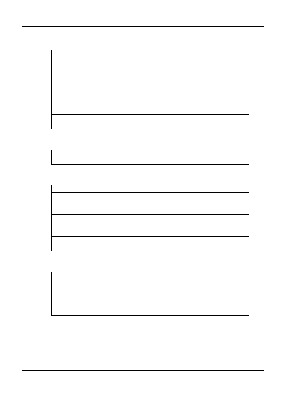
Part Number Description
179215 Dual Source/Sensor Board
179216 Passive I/O Board
179217 IEEE-488 Communication Board
179218 Internal Storage Data/Time Clock
179219 RS-232 to RS-485 conversion
179220 Remote Power Handset
179239 Active I/O Board
123200-5 SH-102 Sensor Head, cables, and
carousel of 10 each 6MHz Gold SC101 sensor crystals
124201-4 SO-100 Oscillator with 6" and 10'
BNC Cables.
130200-2 IF-111 Instrument Feedthrough, 1" O-
Ring with 1 electrical connector and
dual 3/16" water tubes.
130204-2 IF-276 Instrumentation Feedthrough,
2 3/4" Conflat® Flange seal with 1
electrical connector and dual 3/16"
water tubes.
150902 SF-120 Combination Sensor Head,
Feedthrough, Cables, Crystals and
Oscillator.
123204-1 Internal Coax Cable 30".
123204-2 Internal Coax Cable 60".
124202-1 BNC Cable Assembly 10'.
124202-2 BNC Cable Assembly 20'
124204 BNC Cable Assembly 6".
103220 SC-101 Carousel of 10 each 6MHz
gold sensor crystals.
103221 SC-102 Carousel of 10 each 6MHz
silver sensor crystals.
GENERAL DESCRIPTION 1-7
Page 26

Page 27
MDC-360C DEPOSITION CONTROLLER
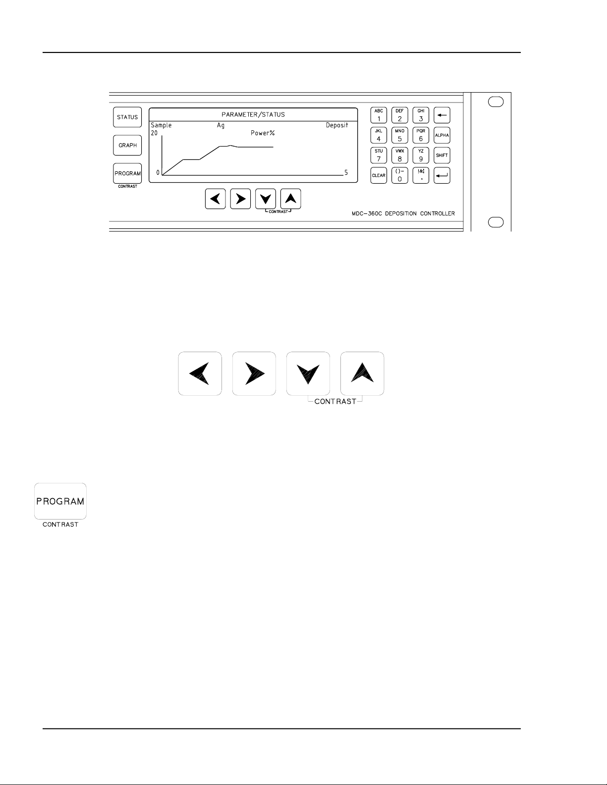
2. FRONT PANEL DISPLAYS AND CONTROLS
The front panel is divided into two sections, the operating section and the
programming section. The left half of the panel is devoted to the operating
displays and controls. The right half is used for programming, viewing stored
processes, and displaying the status of the selected process.
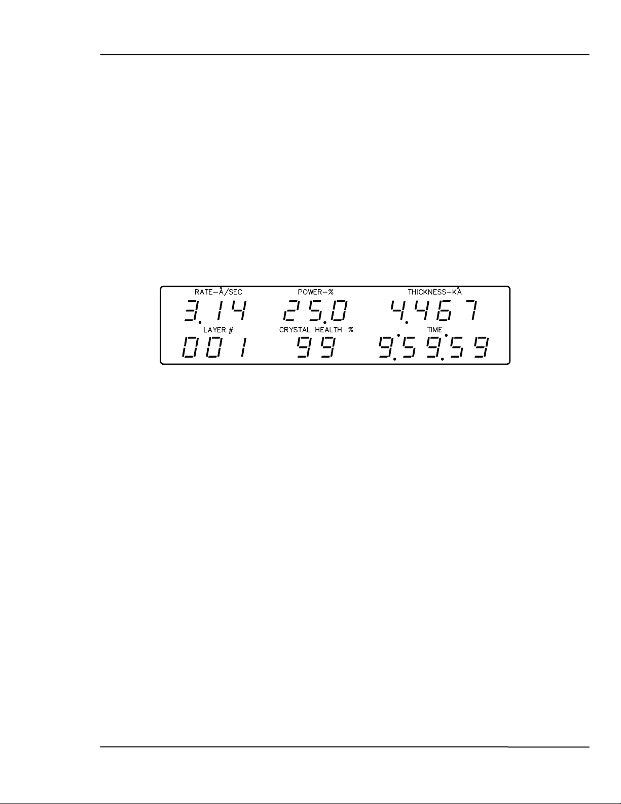
2.1 OPERATING DISPLAYS
All of the operating displays are updated ten times per second unless the
controller is in the Abort mode. When in the Abort mode, the values of the
operating displays are held constant so the operator will know the values at the
time of the Abort. The controller will also flash the operating displays while in
Abort to alert the operator.
Figure 2-1 Operating Display
2.1.1 RATE
A three digit display with a floating decimal point is used to display deposition
rate in angstroms per second at a resolution of 0.1 Å/sec from 0 to 99.9 Å/sec, and
a resolution of 1.0 Å/sec for rates from 100 to 999 Å/sec.
2.1.2 POWER
A three digit display with a fixed decimal point displays percent of maximum
power with a resolution of 0.1% from 0 to 99.9%. This corresponds to the control
voltage range of 0 to 9.99 volts.
2.1.3 THICKNESS
Four digits with an autoranging decimal point display measured thickness in KÅ
with a resolution of 1 Å from 0 to 9.999 KÅ, a resolution of 10 Å from 10.00 KÅ
to 99.99 KÅ and a resolution of 100 Å from 100.0 KÅ to 999.9 KÅ.
2.1.4 LAYER NUMBER
Three digits display the layer number of the current process.
2.1.5 CRYSTAL HEALTH %
A two-digit display is used to show the health percentage of the active
sensor/crystal. If multiple sensors/crystals are active then the crystal with the
lowest health will be displayed. A fresh crystal starts out with a health of 99%.
FRONT PANEL DISPLAYS AND CONTROLS
2-1
Page 28
MDC-360C DEPOSITION CONTROLLER
2.1.6 TIME DISPLAY
Time is displayed in hours, minutes and seconds. This display can be configured
to show the estimated time to go for the state or layer or the elapsed process, layer
or state times.
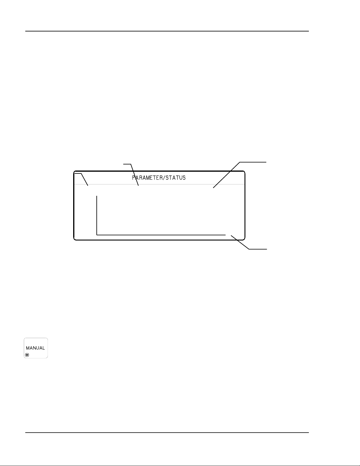
2.2 PARAMETER/STATUS DISPLAYS
A graphics display labeled Parameter/Status is used for process programming and
controller setup as well as displaying run-time status and data graphing. The
operator can switch between programming screens and status screens by pressing
the Program and Status keys on the front panel. Upon power up, the
Parameter/Status display automatically reverts to the last viewed status screen.
Detail descriptions of the different programming and status screens can be found
in Section 4 and 5.
Displays the current
process name.
Figure 2-2 Parameter/Status Display
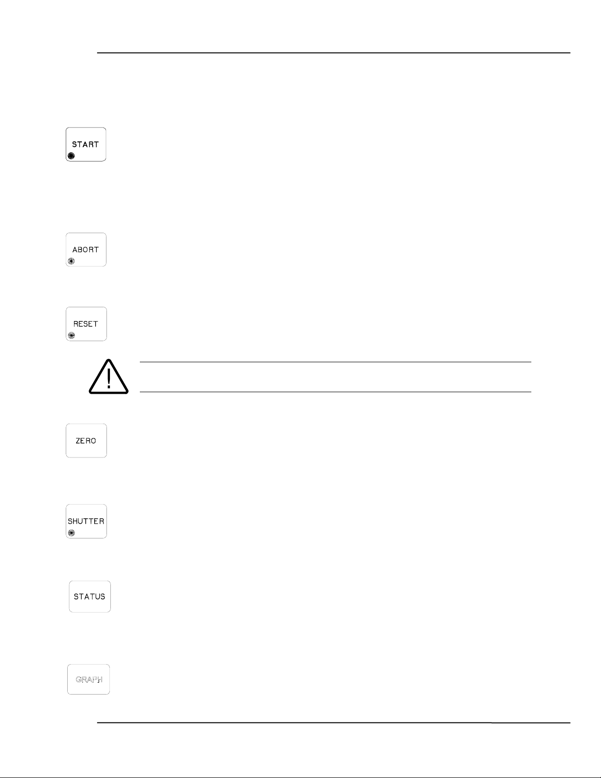
2.3 OPERATING CONTROLS
Normal operation of the MDC-360C is controlled by eight operating keys,
Manual, Start, Abort, Reset, Zero, Shutter, Status, and Graph. Except for the
Zero, Status, and Graph keys, each of the other keys is equipped with an LED to
indicate the controller’s status.
2.3.1 MANUAL KEY
This key is used to toggle the MDC-360C Manual mode on and off. A red light
behind this key indicates the controller is in manual power control mode. This
mode may be selected at any time providing that the controller is not in Abort
mode. The Manual mode indicates that the source control voltage output for the
active source is being controlled through the Remote Power Handset. (The active
source is set by the active material's Source parameter).
Displays the current
material name.
Sample Cr Process Ready
10 Rate
0 1
Displays the
controller modes,
states or troubles.
Displays the time
axis scale factor
In the Manual mode the control voltage remains constant unless incremented up
or down by means of the Remote Power Handset. At entry into the Manual mode,
the power is left at the last value prior to entry and is thereafter modified only
through the Remote Power Handset. Exit from the manual mode is accomplished
by means of the Manual or Reset key.
FRONT PANEL DISPLAYS AND CONTROLS 2-2
Page 29
MDC-360C DEPOSITION CONTROLLER
The MDC-360C can also be aborted through the Remote Power Handset. This
abort feature is active whether or not MDC-360C is in the manual mode.
2.3.2 START KEY
The Start key starts a process, starts a layer, or resumes an aborted process. A
green light behind this key indicates the controller is in process. When this key is
pressed the first time a list of stored processes is displayed in the Parameter/Status
window. You simply scroll the cursor on to the desired process and press Start
again to start the process.
2.3.3 ABORT KEY
The Abort key drives the MDC-360C into the Abort mode. All source powers are
set to zero and discrete outputs are set to inactive state. A red light behind this
key indicates the controller is in the abort mode.
2.3.4 RESET KEY
The Reset key is used to clear the controller from Abort mode and put it into the
Ready mode. A yellow light behind this key indicates a Ready mode. The Reset
key is inactive during the In Process mode so that a premature exit from the In
Process mode requires an abort.
CAUTION: Once a process is reset, it cannot be resumed. Consequently, don't
reset an aborted process if you want to resume it once the problem is cleared.
2.3.5 ZERO KEY
Pressing the Zero key causes the thickness display to go to zero. This key is
active at all times and if pressed during the deposit state will result in a film
thicker than that desired by an amount equal to the thickness displayed at the time
the display was zeroed.
2.3.6 SHUTTER KEY
This key is used to manually open and close all source shutters. The red light is
illuminated when the active source shutter relay is closed. This key is only active
when the controller is in the Process Ready mode.
2.3.7 STATUS KEY
Pressing the Status key will bring up one of the two run-time status screens.
Repeatedly pressing the key will cycle through the different status screens. Refer
to Section 5 for a detailed description of these status screens.
2.3.8 GRAPH KEY
Pressing the Graph key will bring up one of the four run-time graph screens.
Repeatedly pressing the key will cycle through the different graph screens. Refer
to Section 5 for a detailed description of these status screens.
FRONT PANEL DISPLAYS AND CONTROLS
2-3
Page 30
MDC-360C DEPOSITION CONTROLLER
Figure 2-3 Programming Section
2.3.9 ARROW KEYS
The arrow keys are used to navigate through the programming and setup menu
structure. These keys will auto-repeat if they are held down for more than half a
second.
Figure 2-4 Arrow Keys
2.3.10 PROGRAM KEY
Pressing the programming key will bring up the last viewed programming screen.
If a programming screen is already shown, nothing will happen. This key is also
used in conjunction with the Up and Down Arrow keys to adjust the contrast of
the
Parameter/Status display. If the screen background is white then press and
hold the Program and the down arrow keys until the text is easy to read. If the
screen background is blue and the text cannot be seen then press and hold the
Program and the up arrow keys.
FRONT PANEL DISPLAYS AND CONTROLS 2-4
Page 31
MDC-360C DEPOSITION CONTROLLER
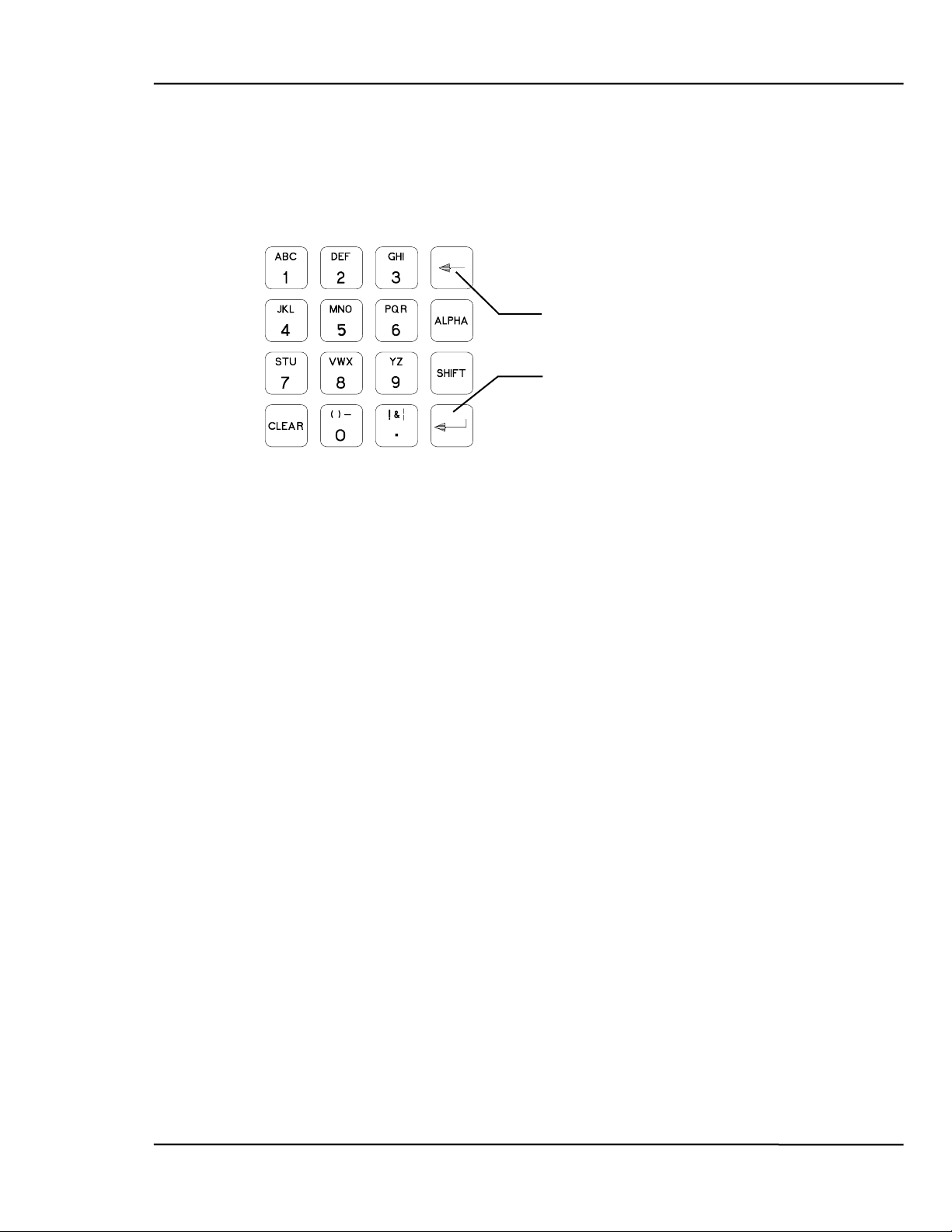
2.3.11 ALPHANUMERIC KEYBOARD
Figure 2-5 Alphanumeric Keyboard
The alphanumeric keyboard is used to
edit controller parameters. Refer to
Section 4 for details on enter new
parameter values.
‘Backspace’
‘Enter’
FRONT PANEL DISPLAYS AND CONTROLS
2-5
Page 32

Page 33

MDC-360C DEPOSITION CONTROLLER
3. BENCH CHECKOUT & INSPECTION
3.1 INSPECTION
Your MDC-360C was released to the carrier in good condition and properly
packed. It is essential to all concerned that the contents of the shipment be
carefully examined when unpacked to assure that no damage occurred in transit.
Check the material received against the packing list to be certain that all elements
are accounted for. Items included with your controller are:
1 MDC-360C Deposition Controller
1 Operation and Service Manual
1 Power cord
1 Source cable (4 pin mini DIN connector)
1 Discrete I/O connector kit (37P D shell)
In addition, you may have ordered one or more of the accessories listed in Section
1.4. If there is evidence of loss or damage:
a) Notify the carrier or the carrier agent to request inspection of the loss
or damage claimed.
b) Keep the shipping containers until it is determined whether or not they
are needed to return the equipment to INFICON.
3.2 INITIAL POWER UP
Upon initial power up the unit will start with all LED’s lighted. The
Parameter/Status display will show the controller Sign-on screen with its
configuration information. See Figure 5-1. The unit will stay in this state until a
key is pressed.
When any key on the front panel is pressed, the operating display and the
Parameter/Status display will return to the last viewed screen prior to loss of
power.
3.3 SAMPLE PROGRAM
The sample program listed below is included in the MDC-360C memory at the
time of shipment. It can be used to check out the controller by running it in
Simulate mode. Follow instructions in Section 4 to navigate through the menu
structure. Check the controller parameter values against the sample program for
discrepancy and change if necessary. Note also, if the source or sensor
configuration has been changed during familiarization with the controller
programming, appropriate source and sensor parameter values also need to be
retained for the sample program to run correctly.
Once the sample program has been checked, use the programming Main Menu,
Edit System Setup, Edit Utility Setup, to select Simulate mode ON, then use Start
to select and run the sample program in Simulate mode.
BENCH CHECKOUT & INSPECTION
3-1
Page 34

MDC-360C DEPOSITION CONTROLLER
3.3.1 MATERIAL #1 PARAMETERS
Material Name Cr
Source # 1
Pocket # 1
Material Density 07.20 gm/cm3
Acoustic Impedance 28.95 gm/cm2 sec
Tooling Factor 100 %
Proportional gain 2400
Integral Time constant 99.9
Derivative Time constant 0.00
Rise to Soak Time 0:00:10 H:MM:SS
Soak Power 5 %
Soak Time 0:00:10
Rise to Predeposit Time 0:00:10
Predeposit Power 9.5 %
Predeposit Time 0:00:05
Rate Establish Time 0 sec
Rate Establish Error 0 %
Deposition Rate #1 10.0 Å/sec
Rate Start Thickness (1 to 4) 100%
Rate Stop Thickness (1 to 4) 100%
Time Setpoint 0
Ramp to Feed Time 0:00:05
Feed Power 7 %
Feed Time 0:00:10
Ramp to Idle Time 0
Idle Power 0
Maximum Power 20 %
Power Alarm Delay 5 sec
Minimum Power 0 %
Rate Deviation Attention 0 %
Rate Deviation Alarm 0 %
Rate Deviation Abort 0 %
Sample Dwell % 100.0 %
Sample Period 0:01:00
Sensor #1 TimePower
Sensor #1 Tooling 70 %
Sensor #1 Weight 100 %
Sensor #1 Crystal # 1
Sensor #1 Backup Sensor # 1
Sensor #1 Backup Crystal # 1
Material Password 0000
BENCH CHECKOUT & INSPECTION 3-2
Page 35

MDC-360C DEPOSITION CONTROLLER
3.3.2 MATERIAL #2 PARAMETERS
Material Name Au
Source # 1
Pocket # 2
Material Density 19.30 gm/cm3
Acoustic Impedance 23.18 gm/cm2 sec
Tooling Factor 100 %
Proportional gain 5000
Integral Time constant 99.9
Derivative Time constant 0.00
Rise to Soak Time 0:00:05 H:MM:SS
Soak Power 25 %
Soak Time 0:00:05
Rise to Predeposit Time 0:00:05
Predeposit Power 37.5 %
Predeposit Time 0:00:10
Rate Establish Time 0 sec
Rate Establish Error 0 %
Deposition Rate #1 20.0 Å/sec
Rate Start Thickness (1 to 4) 100%
Rate Stop Thickness (1 to 4) 100%
Time Setpoint 0
Ramp to Feed Time 0:00:05
Feed Power 10 %
Feed Time 0:00:10
Ramp to Idle Time 0
Idle Power 0
Maximum Power 50 %
Power Alarm Delay 5 sec
Minimum Power 0 %
Rate Deviation Attention 0 %
Rate Deviation Alert 0 %
Rate Deviation Alarm 0 %
Sample Dwell % 100 %
Sample Period 0:01:00
Sensor #1 TimePower
Sensor #1 Tooling 70 %
Sensor #1 Weight 100 %
Sensor #1 Crystal # 1
Sensor #1 Backup Sensor # 1
Sensor #1 Backup Crystal # 1
Material Password 0000
BENCH CHECKOUT & INSPECTION
3-3
Page 36

MDC-360C DEPOSITION CONTROLLER
3.3.3 PROCESS PARAMETERS
Process Name Layer No. Thickness Material
Sample 1 0.400 KÅ Cr
2 1.050 KÅ Au
3.4 SIMULATE OPERATION
Testing the MDC-360C is best accomplished by checking its operation in the
Simulate mode. This mode can be selected by using the programming Main
Menu, Edit System Setup, Edit Utility Setup, to select Simulate mode ON, then
use Start to select and run a process in Simulate mode.
The Simulate mode is identical to the Normal mode except that the sensor inputs
are simulated. For this reason, entry to the Simulate mode will extinguish the
Crystal Failure message if it is flashing. No other difference between the
Simulate mode and the Normal mode occurs until entry to the Deposit State.
3.5 MANUAL OPERATION
Manual Mode is selected by depressing the Manual key. The LED behind the key
will light up indicating the controller is in Manual mode.
The Manual Mode is identical to the normal mode in all respects except that
source power for the active source is controlled only through the Remote Power
Handset.
The Remote Power Handset has three push buttons, see Figure 3-1. Without any
of the buttons depressed, the output power is maintained at its last value.
Depressing the “PWR UP” button will increase the power, depressing the “PWR
DN” button will decrease the power and depressing the “ABORT” button will put
the controller into the Abort mode.
The Abort Mode is active whether or not the MDC-360C is in Manual Mode and
therefore can be used as a remote “panic button”.
The minimum increment by which the power is increased or decreased is 0.1%.
3.6 INSTALLING OPTION BOARDS
Option boards are most easily installed while the MDC-360C is on the bench.
Figure 8-10 shows the location of the various option boards. Also, they are
clearly marked on the rear panel.
All Dual Source-Sensor boards are identical, as are all Discrete I/O boards. The
input-output configuration of these boards is defined by the position into which
they are installed. One exception for the Discrete I/O boards is that the jumper J2
on the board installed in the Discrete I/O-2 position has to be connected. This is
required so the controller will acknowledge the second Discrete I/O board.
A Source-Sensor board plugged into the second position will provide sensor
inputs numbers 3 & 4 and source outputs numbers 3 & 4. A Source-Sensor board
BENCH CHECKOUT & INSPECTION 3-4
Page 37

MDC-360C DEPOSITION CONTROLLER
plugged into the third position will provide sensor inputs numbers 5 & 6, and
source outputs numbers 5 & 6.
3.6.1 SOURCE-SENSOR BOARD
1. Remove the chassis top cover.
2. Remove the three plastic hole-plugs from the rear panel.
3. Carefully slide the two BNC connectors on the Source-Sensor board into
the two top holes on the rear panel. Then with even pressure, push the
card edge connector down into the Main board at J12, J13 or J14.
4. Fasten the two BNC connectors using the nuts and washers supplied with
the kit. Make sure the board is properly aligned.
5. Tighten the board down with the tie wrap.
6. Replace the chassis top cover and apply power to the controller.
7. The Sign On screen should acknowledge a new Source-Sensor card
installed.
3.6.2 DISCRETE I/O BOARD
1. Remove the chassis top cover.
2. Locate Discrete I/O-2 slot and remove the slot cover.
3. Carefully slide the D37 connector of the DIO board into the slot and fasten
it using the hex fasteners and washers supplied with the kit.
4. Fasten the other end of the board to the standoffs using the two # 4-40
screws provided.
5. Plug the 26-pin ribbon connector into the DIO edge connector J1.
6. Replace the chassis top cover and apply power to the controller.
7. The Sign On screen should acknowledge Discrete I/O-2 installed.
3.6.3 IEEE-488 OPTION BOARD
1. Remove the chassis top cover.
2. Locate the IEEE-488 option slot and remove the slot cover.
3. Carefully slide the connector of the IEEE-488 board into the slot and fasten
it using the fasteners and washers supplied with the kit.
4. Plug the 20-pin ribbon connector into J7 connector on the Main board.
5. Replace the chassis top cover and apply power to the controller.
6. The Sign On screen should acknowledge IEEE-488 option installed.
3.7 DIGITAL TO ANALOG CONVERTER (DAC) CHECKOUT
The built-in DAC function on the Main board contains two converters, allowing
simultaneous recording of any two of the following four parameters: Rate, Rate
deviation, Power and Thickness. The full-scale output of each converter is 5
volts, is single ended and is referenced to ground. Parameter selection for each of
the channels is accomplished independently by making the appropriate choices in
the DAC setup menu.
In addition to the individual channel output pins there are two control pins which
are common to both channels and are intended to simplify the process of setting
up analog recorders. Connecting the Zero control line to ground will drive both
channel outputs to zero, allowing the recorder zero reference to be easily set.
BENCH CHECKOUT & INSPECTION
3-5
Page 38

MDC-360C DEPOSITION CONTROLLER
Releasing the Zero line and connecting the Full Scale line to ground will drive
both channel outputs to full scale for establishing the recorder full scale
calibration.
Each channel can be set independently to convert either the two or the three least
significant digits of the chosen parameter to a proportional analog signal,
corresponding to the DAC setup option chosen. With the three-digit setting, a
thickness of 0.500 KÅ would result in an analog output of 2.50 volts, or a scale
factor of 5 mV/Å. If more resolution is desired, either channel can be configured
to convert only the last two digits of the parameter, thus the analog output would
achieve full scale at 99Å. The output scale factor in this configuration is 50
mV/Å.
The above scale factors are based on the assumption that the thickness display is
in the 0 - 9.999 KÅ range. Because the thickness and rate displays are autoranging, the analog output of these variables will also autorange so that in the
above example, if the thickness is in the range of 10 KÅ to 99.9 KÅ, the analog
scale factor would be 50 millivolts per 10 Å, also ten times larger.
The Rate deviation parameter must be handled differently than the other
parameters because it can be negative. Maximum positive error is converted to 5
volts, maximum negative error is converted to 0 volts and zero error is converted
to a mid scale, 2.5 volt, output. Maximum corresponds to 99 or 999, plus 1.
The DAC can be checked by putting the MDC-360C into the Simulate mode and
checking for correspondence between the analog output and the selected front
panel displays.
BENCH CHECKOUT & INSPECTION 3-6
Page 39

MDC-360C DEPOSITION CONTROLLER
Figure 3-1 Remote Power Handset
BENCH CHECKOUT & INSPECTION
3-7
Page 40

Page 41

MDC-360C DEPOSITION CONTROLLER
4. PROGRAMMING AND CONTROLLER SETUP
4.1 GENERAL
4.1.1 NAVIGATING THE MENU STRUCTURE
Before attempting to navigate the menu structure of the MDC-360C controller,
please refer to Section 2 which provides a brief summary of the front-panel
displays and key functions. A graphical menu structure is shown in Figure 16-2.
Note that first key press following power-on will bring up the display function
used when power was switched off, i.e. either a status display screen or a
programming screen.
This may be confusing until the full scope of the controller’s capabilities are
understood. However, as their names suggest, the Status, Graph and Program
keys select the display of status screens, graph screens and programming screens,
respectively. Also note that the last viewed screen for each type is remembered
and will be displayed the next time that display type is selected.
Main Menu
View/Edit Process..
View/Edit Material
View Results
Edit System Setup
Figure 4-1 The Main Menu
Press the Program key to enter the programming mode. The programming
screens can be visualized as a two-dimensional menu format. The Main Menu is
visualized at the far left, with an increasing level of detail in the menus to the
right. The Left and Right-arrow keys are used to move between menus. The Up
and Down-arrow keys are used to scroll through a list of parameters or options in
each menu. To select a menu option, highlight it, then press either the Enter key
or the Right-arrow key. This will present the next screen associated with the
selected option. Please note that holding the Left arrow key will always bring
you back to the Main Menu screen no matter where you are in the menu
structure.
Each of the programming screens is described in detail later in this section.
4.1.2 ENTERING ALPHA CHARACTERS
To enter a name, press the key that contains the letter or character you wish to
enter. Next, press the Alpha key to change the number to the first letter of that
PROGRAMMING AND CONTROLLER SETUP 4-1
Page 42

MDC-360C DEPOSITION CONTROLLER
key. Keep pressing the Alpha key to get the desired letter. Its upper/lower case
can be toggled by pressing the Shift key. Once the desired letter is achieved,
repeat the above procedure and enter the remainder of the name. Note, the
number 9 key contains characters Y, Z, and ‘space’. Use this key to enter a space.
4.1.3 ENTERING TIME PARAMETERS
The MDC-360C expresses time in 24-hour h:mm:ss format. In programming a
time parameter, the Decimal ‘.’ key is used to separate hour, minute and second.
Hence, 1:45:23 would be entered as “1.45.23” and 0:00:35 entered as “..35”,
followed by the Enter key.
4.1.4 COPYING AND DELETING
A ‘process’ is defined by one or more ‘layers’, and a layer requires a ‘material’
and a thickness definition. The MDC-360C has the capability of copying and
deleting processes, layers, and materials. Except when copying a layer,
procedures for copying and deleting a process, a layer and a material are the same.
The difference when copying a layer is that layers are pushed-down to make
space for the new layer, and move up when a layer is deleted.
To copy a process, position the cursor at the process to be copied, then press the
number 1 key. Next, move the cursor to the location where the process is to be
copied and press Enter. The process will be copied to the new location with the
same name. If there is already a process name at the new location, it will be
overwritten. The copied process should be given a new name to avoid
confusion. The same procedure applies when copying a material.
When copying a layer, the copied data will be positioned at the selected layer
number. The data of the selected layer, and all following layers, will be pushed
down one layer. Example, if a layer is copied onto Layer #4 location, the existing
data in Layer #4 will be pushed to Layer #5, Layer #5 to Layer #6, etc., while the
copied data is placed in Layer #4.
CAUTION: Use below instruction carefully as deleted items are not
recoverable.
To delete a process or a material, move the cursor to the item and press the 0 key.
A message will pop up asking for verification of the deletion, press 1 to confirm
or 0 to cancel the deletion.
4.1.5 PASSWORD PROTECTION
NOTE: The password protection is only meant to deter unsophisticated users.
Be sure to record passwords, because if you forget a password it will not be
possible to gain access to the protected item!
Each Process has a View/Run password and an Edit password. Each Material has
an Edit password. The three passwords protect against unauthorized operations.
The passwords default to 0000, or no password protection, at the time of
shipment. Refer to the descriptions below to set each password.
PROGRAMMING AND CONTROLLER SETUP 4-2
Page 43

MDC-360C DEPOSITION CONTROLLER
4.1.5.1 VIEW/RUN PROCESS PASSWORD
The View/Run password is required to view or run a process. To set this
password, select View/Edit Process from the Main Menu, select the process from
the Select Process screen. Move the cursor onto the View/Run password, type in
your password (4-digit string), and then press the Enter key. A message will pop
up asking for verification to change the password. Press 1 to confirm and 0 to
cancel the change. Each time you want to view or run this process, you will now
be asked to enter the correct password. Note that the Edit Process password takes
precedence over the View/Run password. If you know the Edit password, you
can also view the process. Once a password other than 0000 has been installed, it
will not be displayed unless re-entered.
4.1.5.2 EDIT PROCESS PASSWORD
The Edit process password is required to edit a process. To set this password,
select View/Edit Process from the Main Menu, select the process from the Select
Process screen. Move the cursor onto the Edit password, type in your password
(4-digit string), then press the Enter key. A message will pop up asking for
verification to change the password. Press 1 to confirm and 0 to cancel the
change. Each time you want to edit this process, you will be asked to enter the
correct password. Once a password other than 0000 has been installed, it will not
be displayed unless re-entered.
4.1.5.3 EDIT MATERIAL PASSWORD
The Edit material password is required to edit a material. To set this password,
select View/Edit Material from the Main Menu, select the material from the
Select Material screen. Move the cursor down to the Material Password
parameter, the last item in the list, type in your password (4 digit string), then
press the Enter key. A message will pop up asking for verification to change the
password. Press 1 to confirm and 0 to cancel the change. Each time you want to
edit this material, you will be asked to enter the correct password. Once a
password other than 0000 has been installed, it will not be displayed unless reentered.
4.1.6 ADJUSTING PARAMETER/STATUS DISPLAY CONTRAST
The Parameter/Status display contrast can be adjusted by using the Program key
in conjunction with the Up-arrow and Down-arrow keys. Hold down the Program
key and press the Up-arrow key to increase the contrast. Likewise, hold down the
Program key and press the Down-arrow key to decrease the contrast. It may take
several seconds for the change in contrast to become apparent.
4.2 GETTING STARTED
This section is intended to help new users quickly program the MDC-360C for
basic applications. The section gives the best programming sequence and lists
programming examples. See DETAILED PROGRAMMING in section 4.3 for a
complete programming description.
PROGRAMMING AND CONTROLLER SETUP 4-3
Page 44

MDC-360C DEPOSITION CONTROLLER
4.2.1 UTILITY SETUP
The only critical parameter in the Utility Setup is the Crystal Frequency
parameter. This parameter must be set for the specific frequency crystals that you
plan to use (2.5, 3.0, 5.0, 6.0, 9.0, 10.0 MHz).
There is one other parameter in the Utility Setup menu that may be useful in the
initial setup and testing phase of the MDC-360C and that is the Simulate Mode
parameter. The Simulate mode of the MDC-360C provides a means of simulating
deposition on the crystal. This mode is useful for testing the setup of the MDC360C without having to deposit any material.
4.2.2 DAC SETUP
If the DAC (digital to analog) outputs are to be used then these parameters can be
set at this time but it is not necessary for the operation of the controller.
4.2.3 SOURCE SETUP
The first item to note is that in defining sources, and sensors for that matter, is that
the MDC-360C will automatically create the inputs and outputs necessary to
complete the interface based on the parameter settings. Therefore, once the setup
is complete, the user should review the inputs and outputs noting the pin
assignments so that the proper connections can be made. Also note that the I/O
pin assignments can be changed if necessary in the program input and output
screens.
The user must also be aware of the type of I/O card installed in the MDC-360C.
There are two types of I/O cards available. Both cards have the same 9 relay
outputs (8 programmable and 1 abort) and the same number of inputs (8
programmable). The difference is the standard card has TTL ground true inputs
while the Active I/O card has 115VAC high true inputs. The Active I/O card is
designated by “Active I/O Card” written on the rear panel of the MDC-360C.
The following two items in the Source Setup are common to almost all types of
sources and typically require definition:
Source Shutter - If the source has a shutter to be activated by the MDC-360C
then the Shutter Relay Type parameter must be set to either N.O.
(normally open) or N.C. (normally closed). The typical setting is N.O.
which means that the relay will close to open the shutter.
Once defined, the MDC-360C will create a relay output called “SourceN
Shutter” that should be connected to the shutter actuator. The shutter can
be tested by pressing the Shutter key with the controller in the Process
Ready state. When the red LED in the Shutter key is illuminated then all
source shutters should be opened. When the shutter LED is off then all
source shutters should be closed.
If the shutter actuator has a significant delay in opening and closing then set
the Shutter Delay parameter equal to the delay.
PROGRAMMING AND CONTROLLER SETUP 4-4
Page 45

MDC-360C DEPOSITION CONTROLLER
Source Voltage - This parameter must be set to correspond to the input
voltage range of the source power supply (0 to 2.5, 5.0 or 10.0 volts).
The settings of the rest of the source parameters are dependent on whether the
source has one or more pockets (crucibles) and whether pocket selection is
manual or automatic.
Single Pocket Source - If the source has only one pocket (single pocket E-
beam gun, filament boat or sputtering source) then the remaining
parameters can be left at their default values.
Multiple Pocket Source with Manual Position Control - For manual
position control of a multiple pocket source, you need only set the Number
of Pockets parameter to the correct number of pockets. Once set, a
message will appear at the start of each layer instructing the operator to
change source N to the required material.
Multiple Pocket Source with Automatic Position Control - There are two
parameters requiring definition which are common to all the various types
of position control. The first is the Number of Pockets parameter and the
second is the Rotator Delay parameter. The Number of Pockets parameter
is simply the number of pockets in the source. The Rotator Delay
parameter defines the maximum amount of time allowed for the correct
pocket to rotate into position. This should be set to the time it takes for
the rotator to go from pocket #1 all the way around to pocket #1 again.
The settings of the three remaining parameters required for automatic
pocket position control depends on the required type of position control
and position feedback.
Position Control - The MDC-360C can be setup to either control the
pocket position directly by interfacing to the rotator’s actuator or
indirectly by interfacing to a rotator controller.
Direct Control of Pocket Position - Direct control means that the MDC-
360C will control the actuator (rotator motor, pneumatic valve, etc.)
directly to get the desired pocket into position. For direct control first
set the Control Parameter to Direct then select one of the following
drive types and follow the instructions:
a. Unidirectional Motor Drive - The rotator drive motor can only turn in
one direction. Select Up for the Drive parameter. A relay output
will be created called “SourceN Drive Up” that should be connected
between the rotator motor and power supply.
b. Bi-directional Motor Drive - The rotator motor can turn in either
direction. Select Fast for the Drive parameter. Two relay outputs
will be created. One called “SourceN Drive Up” and one called
“SourceN Drive Dn”. With this drive type, the MDC-360C will
activate either the drive up or drive down outputs to rotate to the
required pocket in the least amount of time.
PROGRAMMING AND CONTROLLER SETUP 4-5
Page 46

MDC-360C DEPOSITION CONTROLLER
c. Motor Driven Inline Source - Select Inline for the Drive type
parameter. Two relay outputs will be created. One called
“SourceN Drive Up” and one called “SourceN Drive Dn”. In this
case the up output will be activated when going from the greatest
pocket to pocket #1.
d. Unidirectional Pneumatic Drive - Select Sngl Step or Dbl Step for the
Drive parameter. A relay output will be created called “SourceN
Drive Up” that should be connected between the rotator’s
pneumatic valve and power supply. With Sngl Step, the output will
pulse once for one second to increment the rotator one position.
With Dbl Step, the output will pulse twice for one second each to
increment the rotator one position.
Indirect Control of Pocket Position - Indirect control means that the MDC-
360C will indicate the desired pocket position to a pocket rotator
controller through position select outputs. The Drive parameter selects
between the two following indirect position output formats:
a. Individual - With individual format, one output will be created
for each pocket. So, if pocket 2 is the desired pocket, then the
output “SourceN Pocket 2” will be true while all the other position
outputs will be false.
b. BCD - With BCD format , the MDC-360C will create from one
to three outputs based on the number of pockets. For example, an
eight pocket source would use three outputs. If pocket one is the
desired pocket, all outputs will be false. If pocket four is the
desired pocket, outputs one and two will be true and output three
will be false.
Position Feedback - The last step in defining automatic control of a multi-pocket
source is to select the pocket position feedback type. The MDC-360C has the
following five types of position feedback available:
No Feedback - As the name implies, no position feedback is created for this
type.
Individual - For this feedback type, one input is created for each pocket
position in the source. The inputs are labeled “SourceN Pocket X”. All
inputs are normally false (open circuit) unless the respective pocket is in
position then that input should be true (closed to ground). For example, a
six pocket source would use six inputs. If pocket two was in position then
all the inputs should be false except the input connected to “SourceN
Pocket 2”.
Individual position feedback is the most typical feedback type and is
recommended if more than one type is available.
BCD - Binary Coded Decimal position feedback. This feedback type uses
binary coding to indicate the pocket position. Inputs are numbered most
significant bit first. For example, an eight pocket source would use three
PROGRAMMING AND CONTROLLER SETUP 4-6
Page 47

MDC-360C DEPOSITION CONTROLLER
inputs. With pocket one in position, all inputs will be false. With poctket
four in position, inputs one and two will be true and input three will be
false.
SNGL HOME - Single home position feedback. This feedback type uses one
input. The input is normally false (open circuit) and should go true
(closed to ground) when pocket one is in position.
IN POSITION - In position feedback. This feedback type uses one input.
The input is normally false (open circuit) and should go true (closed to
ground) when the desired pocket is in position.
4.2.4 SENSOR SETUP
The following examples demonstrate how the MDC-360C is setup to control the
four basic types of crystal sensor heads available:
Single Crystal Sensor Head - No sensor parameters need to be changed for a
single crystal sensor head.
Single Crystal Sensor Head with Shutter - For a single shuttered sensor
head, set the Shutter Relay Type parameter to either N.O. (normally open)
or N.C. (normally closed). The typical setting is normally open which
means that the relay will close to open the shutter. A relay output called
“SensorN Shutter” will be created that should be connected between the
sensor shutter actuator and power supply.
Dual Crystal Sensor Head with Shutter - For a dual crystal shuttered sensor
head, set the Shutter Relay Type parameter to Dual. A relay output called
“DualSnsr1&2 Shtr” will be created that should be connected between the
sensor shutter actuator and power supply.
Automatic crystal switching upon failure is enabled in the material menu
by setting the Crystal Fail parameter to Switch and the Backup Sensor
number to 2. Note that with the dual sensor head you define the sensor
number that you would like to use, (or switch too) not the crystal number.
The crystal number need only be defined when you are using a multiple
crystal sensor head (sensor head with one BNC output and more than one
crystal).
Multiple Crystal Sensor Head - The MDC-360C can be setup for either
automatic or manual control of multiple crystal sensor heads.
a. Manual Crystal Position Control - For manual crystal position
control of a multiple crystal sensor head, set the Number of Crystals
parameter to the correct number of crystals. Once set, a message will
appear at the start of each layer instructing the operator to change
sensor N to the required crystal number.
b. Automatic Crystal Position Control - There are two parameters
requiring definition which are common to all the various types of
multiple sensor heads. The first is the Number of Crystals parameter
and the second is the Rotator Delay parameter. The Number of
PROGRAMMING AND CONTROLLER SETUP 4-7
Page 48

MDC-360C DEPOSITION CONTROLLER
Crystals parameter defines the number of crystals in the sensor head.
The Rotator Delay parameter defines the maximum amount of time
allowed for the correct crystal to rotate into position. This should be
set to the time it takes for the rotator to go from crystal #1 all the way
around to crystal #1 again.
The settings of the three remaining parameters required for automatic
crystal position control depend on the type of position control and
position feedback.
Position Control - The MDC-360C can be setup to either control the
crystal position directly by interfacing to the rotator’s actuator or
indirectly by interfacing to a rotator controller.
Direct Control of Pocket Position - Direct control means that the
MDC-360C will control the actuator (rotator motor, pneumatic
valve, etc.) directly to get the desired crystal into position. For
direct control, set the Control Parameter to Direct then select
one of the following drive types and follow the instructions:
a. Unidirectional Motor Drive - Select Up for the Drive
parameter. A relay output will be created called “SensorN
Drive Up” that should be connected between the rotator
motor and power supply.
b. Bi-directional Motor Drive - Select Fast for the Drive
parameter. Two relay outputs will be created. One called
“SensorN Drive Up” and one called “SensorN Drive Dn”.
With this drive type, the MDC-360C will activate either the
drive up or drive down outputs to get to the required crystal
in the least amount of time.
d. Unidirectional Pneumatic Drive - Select Sngl Step or Dbl
Step for the Drive parameter. A relay output will be created
called “SensorN Drive Up” that should be connected
between the rotator’s pneumatic valve and power supply.
With Sngl Step, the output will pulse once for one second to
increment the rotator one position. With Dbl Step, the
output will pulse twice for one second each to increment the
rotator one position.
Indirect Control of Crystal Position - Indirect control means that the MDC-
360C will indicate the desired crystal position to a crystal rotator
controller through position select outputs. . The Drive parameter selects
between the two following indirect position output formats:
a. Individual - With individual format, one output will be created
for each crystal. So, if crystal 2 is the desired crystal, then the
output “SensorN Crystal2” will be true while all the other position
outputs will be false.
PROGRAMMING AND CONTROLLER SETUP 4-8
Page 49

MDC-360C DEPOSITION CONTROLLER
b. BCD - With BCD format , the MDC-360C will create from one
to three outputs based on the number of crystals. For example, an
eight crystal sensor head will use three outputs. If crystal one is
the desired crystal, all outputs will be false. If crystal four is the
desired crystal, outputs one and two will be true and output three
will be false.
4.2.4.1 EXAMPLE USING INFICON’S RSH-600 SIX CRYSTAL SENSOR HEAD
The following is a list of the sensor parameter settings required to control
INFICON’s RSH-600 six crystal sensor head.
Number of Crystals - 6
Shutter Relay Type - None
Control - Direct
Drive - Sngl Step
Feedback Type - Indiv
Rotator Delay - 30
With the above parameter settings, the MDC-360C will create six position
feedback inputs called “SensorN CrystalX” where X ranges from 1 to 6
and one control output called SensorN Drive Up.
The inputs should be connected to the six position feedback pins on the
RSH-600 sensor head. Pin #1 of connector J1 on the sensor head should
be connected to the “SensorN Crystal1” input on the MDC-360C. Pin #2
on the sensor head should be connected to “SensorN Crystal2” on the
MDC-360C and so on. Pin #7 on the sensor head should be connected to
pin #12 or any of the return pins when using the standard MDC-360C I/O
board. When using the MDC-360C Active I/O board then pin #7 of the
sensor head should be connected to one side of a 115VAC source. The
other side of the 115VAC source should be connected to the other side of
the six position feedback inputs on the MDC-360C.
One pin from the SensorN Drive Up output should be connected to the
115 VAC voltage source and the other to J1. The remaining pin on J1
should connect to the other side of the 115 VAC power supply. In this
configuration, combined with the “single step” drive type, whenever the
MDC-360 needs to change crystals it will close the SensorN Drive Up
output for one second. This completes the circuit applying the 115 VAC
to the RSH-600.
4.2.5 INPUT, OUTPUT AND ACTION SETUP
The MDC-360C’s inputs, outputs and actions can be used to provide control for,
or an interface to all sorts of vacuum system peripherals such as PLC system
controllers, substrate heaters, planetary rotators, etc. If your system doesn’t
require any special interfacing or control then you can skip to the next section.
PROGRAMMING AND CONTROLLER SETUP 4-9
Page 50

MDC-360C DEPOSITION CONTROLLER
The following are a few examples of some typical uses for the MDC-360C’s
programmable I/O’s and actions.
Optical Monitor Termination - To setup the MDC-360C to terminate the
deposit on a signal from an optical monitor, the first step is to program an
input that will be connected to an output in the optical monitor. Go to the
Program Inputs screen and select a blank input. Name the input “Optical
Monitor” for future identification. Note the I/O card and the pin numbers
of the input so you can later connect the input to the optical monitor.
Next, go to the Program Actions screen and select any action labeled “No
Action”. Press the right arrow key with the cursor on the action Name
parameter and select the TerminateDeposit action. Move the cursor to the
Conditions field and press the 0 key to add a condition. Move the cursor
down to the Input condition type, press the right arrow key, move the
cursor onto the “Optical Monitor” input and press enter. Press enter again
to complete the condition string.
Now, the MDC-360C will terminate the deposit whenever the “Optical
Monitor” input is set true by the optical monitor.
Substrate Heat Control - To create an output in the MDC-360C to switch on
and off a substrate heat controller, first go to the Program Outputs screen
and select a blank output. Name the output “Substrate Heat” for future
identification. Note the I/O card number and the pin numbers of the
output so you can later connect the output to the substrate heater
controller.
Next, move the cursor onto the Conditions field and press the 0 key to add
a condition. With the cursor on the State condition type, press the right
arrow key and select the state in which you would like the heater to first
turn on. If you would like the heater on during more than the one state,
then press the 5 key to add an or “|” symbol then press 0 to add the next
desired state. Repeat this process until all of the states requiring substrate
heat have been added to the condition. For example, if you would like
substrate heat to start in the Predeposit Hold state and continue through the
Deposit 1 state then your condition string would look like this “Predeposit
Hold|Deposit 1”.
With the condition string completed, the MDC-360C will set this output
true whenever it is in one of the selected states.
4.2.6 DISPLAY SETUP
The only parameter in the Display Setup menu that affects the controller’s
function is the Pause On Layer Complete parameter. This parameter determines
whether or not the controller will pause at the completion of each layer. When set
to Yes, the controller will stop at the end of each layer and wait for a Start key
press before continuing. When set to No, the controller will immediately go to
the next layer.
PROGRAMMING AND CONTROLLER SETUP 4-10
Page 51

MDC-360C DEPOSITION CONTROLLER
4.2.7 MATERIAL SETUP
The next step in the initial setup of the controller is to define the materials that
you wish to deposit. Because of its many features, the MDC-360C has a long list
of material parameters which at first can be overwhelming. Fortunately, the
default settings of most parameters are such that the feature they define is
disabled when left at the default. This section will list the material parameters
typically set for all materials and the parameters which must be set to utilize the
different features of the MDC-360C. For a detailed description of any material
parameter, go to Section 4.3.2.1.
The following is a list of the material parameters that are typically set wh en
defining a new material:
Process Name - If you select a material from the default material library (press the
right arrow key from the material name parameter and press enter on the
desired material) then the density and acoustic impedance for that material
will be entered automatically. If your material is not in the library then you
must enter the name, density and acoustic impedance.
Source output and pocket number - Defines the source and pocket number of the
source that the material will be deposited from.
Control loop parameters (Proportional Gain, Integral Time, Derivative Time).
The default settings for these parameters are a good starting point.
Deposit Rate #1 - Defines the target deposit rate for the material.
Maximum Power - Defines the maximum deposit power for the material.
Configure Sensors -
Sensor Weight - Should be left at 100% assuming only one sensor is used for
measurement.
Sensor Tooling - Used to correlate each sensor's rate and thickness readings
with those on the substrates. This parameter should be determined empirically
using the Calibrate Sensors feature described in section 10.6.2.
The above parameters are typically all that are needed to deposit the most basic
materials. If no other features are required then the remaining parameters can be
neglected. The following is a list of the more specialized features defined by the
material parameters. All of the features are disabled by default.
4.2.7.1 POWER RAMPS
Power ramps are used for source material conditioning prior to and after the
deposit states. A power ramp is defined by a ramp time, a ramp too power level
and a hold time before the next state. There are two power ramps available prior
to and one after the deposit states. The first ramp prior to deposit is the soak and
the second is the predeposit. If only one ramp is needed prior to deposit then you
should use the predeposit ramp. The power ramp after the deposit states is called
the Feed.
The parameters used to define the three power ramps are as follows:
PROGRAMMING AND CONTROLLER SETUP 4-11
Page 52

MDC-360C DEPOSITION CONTROLLER
Soak Power Ramp - Rise to Soak Time, Soak Power and Soak Time
Predeposit Power Ramp - Rise to Predeposit Time, Predeposit Power and Ramp
to Feed Time
Feed Power Ramp - Ramp to Feed Time, Feed Power and Feed Time
4.2.7.2 AUTOMATIC CRYSTAL SWITCHING
To enable automatic Crystal switching upon failure, set the Fail parameter in the
Configure Sensors screen to Switch then set the Backup Sensor and Backup
Crystal parameters to define what to switch to.
4.2.7.3 RATE ESTABLISH
The rate establish feature is used in critical processes where it is important to
establish the correct deposition rate prior to opening the source shutter and
depositing on the substrates. To use this feature, the sensor head must be
mounted in such a way that it is in the material vapor stream with the source
shutter either opened or closed.
NOTE: To use this feature, the sensor head must be mounted in such a way
that it is in the material vapor stream with the source shutter either opened or
closed.
To enable this feature you must set the Rate Estab. Time and Rate Estab. Error
parameters. The Rate Establish Time parameter sets the maximum time that the
controller will attempt to keep the rate error within the Rate Estab. Error limit for
a period of five seconds. If the rate error condition is meet within the allotted
time then the controller will enter the deposit state. If not, then the process will be
halted and a Rate Establish Error will be displayed.
4.2.7.4 RATE RAMPS
Rate ramping is typically used at the beginning of the deposition to ease the rate
up slowly to prevent material spitting. Rate ramping is also used towards the end
of the deposition to achieve a more accurate endpoint thickness. By slowing
down the rate, the thickness overshoot caused by the delay of the shutter closing
is diminished
The MDC-360C has four rate ramps available. A rate ramp is defined by its
Ramp Start and Ramp Stop Thickness % and the next rate. For example, to setup
the MDC-360C to deposit at 20Å/sec for 90% of the layer, then ramp down to 5
Å/sec over the last 10%, you would enter the following material parameters:
Deposit Rate #1 = 20Å/sec
Ramp Start Thk #1 = 90%
Ramp StopThk #1 = 100%
Deposit Rate #2 = 5Å/sec
PROGRAMMING AND CONTROLLER SETUP 4-12
Page 53

MDC-360C DEPOSITION CONTROLLER
The rate ramps are disabled by default with the Ramp Start and Ramp Stop
Thicknesses set to 100% since 100% represents the end of deposition for the
layer.
4.2.7.5 RATE SAMPLE MODE
Rate sample feature is designed for large deposition thicknesses where crystal life
is a problem. By sampling the rate periodically to maintain rate control, then
closing the sensor shutter with the rate and power level constant, a large
deposition thickness can be achieved with one crystal.
To enable the rate sample feature, set the Sample Dwell% parameter to the
percentage of time you wish the controller to sample the rate. Then set the
Sample Period parameter to the time period of the sample and not sampling
period.
4.2.7.6 RATE DEVIATION ALARM
The MDC-360C provides three rate deviation levels to trigger an attention sound,
an alarm sound, or a process abort. The attention and alarm sounds are
momentarily triggered meaning they will sound when the error is exceeded and
clear when within the limit. The process will abort when the abort level is
exceeded and the power is at the maximum or minimum power.
4.2.8 PROCESS SETUP
The final step in the initial setup of the controller is to define the processes that
you wish to run. To define a process you should complete the following steps:
1. Select a blank process from the Select Process Screen. Please note that you
can also copy and modify a similar process to save time.
2. Enter a process name in the Define Process Screen.
3. Move the cursor onto the layer thickness parameter and enter the desired
thickness for the layer.
4. Select a material for the layer by moving the cursor onto the material column,
pressing the right arrow key, moving the cursor onto the desired material for
the layer and pressing the Enter key.
Repeat steps 3&4 until the process layers are complete.
4.2.9 STARTING A NEW PROCESS
To start a new process, the controller must be in the Process Ready State. If not,
press abort then reset. From the ready state, press the Start key, move the cursor
onto the desired process and press start again to start the process. To start a
process from a layer other layer #1, press the left arrow key to move the cursor
onto the Starting Layer parameter, enter the desired layer number, move back to
the desired process and press Start again. Please note that you can also change the
process Run Number from the Start Process screen.
PROGRAMMING AND CONTROLLER SETUP 4-13
Page 54

MDC-360C DEPOSITION CONTROLLER
y
4.2.10 RESUMING A PROCESS FROM ABORT OR HALT
To resume an aborted process, first press the start key. A message will appear
asking you to press the start key again to resume the process. The process will
resume from the layer where the process was aborted starting in either the Rise to
Soak or Rise to Predeposit power states. Once in deposit, the thickness will
continue from the last value prior to the abort.
4.3 DETAILED PROGRAMMING
This section covers all of the MDC-360C programming in detail.
4.3.1 VIEW/EDIT PROCESS
Selecting View/Edit Process from the Main Menu will present the Select Process
screen to delete, copy, view or edit any one of up to 99 processes.
To select a process for viewing and editing, move the cursor onto the desired
process using the Up-arrow and Down-arrow keys, then press the Enter key.
Select Process: 01 Cr----------
02 Au
03
04
05
1 - Copy 06
0 - Delete 07
- View/Edit 08
Figure 4-2 Select Process screen
4.3.1.1 DEFINE A PROCESS
View or Run Password
Process Name Layer# Thickness Material
Sample------ 001 0.500 Cr
View/Run 0000 002 1.350 Au
Edit 0000 003 0.000 End Layer
004 0.000 End Layer
005 0.000 End Layer
006 0.000 End Layer
007 0.000 End La
er
Edit Password
Figure 4-3 Define Process screen
Selecting a process will bring up the Define Process screen as shown in Figure
4-3. In this screen you enter all of the parameters that define a process. A
PROGRAMMING AND CONTROLLER SETUP 4-14
Page 55

MDC-360C DEPOSITION CONTROLLER
process consists of a twelve-character name, two levels of passwords and finally a
sequence of layers that makeup the process. Each layer consists of a material and
the desired thickness for the layer. A process can have from 1 to 999 layers as
long as the total number of layers in all the processes is not greater than 999. The
following list describes all of the process parameters:
Process Name (twelve character alphanumeric field)
Each process is referenced by a twelve-character alphanumeric process name.
You enter a process name using the alphanumeric keypad as described in Section
4.1.2. Please note that the active process name is displayed in the upper left-hand
corner of all the status screens.
Edit Password (four character alphanumeric field)
The Edit process password allows you to lock out other users from editing a
process unless the correct password is known. To set this password, highlight the
Edit password field, type in your password then press the Enter key. A message
will pop up asking for verification to change the password. Press 1 to confirm
and 0 to cancel the change. Each time you want to edit this process, you will be
asked to enter the correct password. Once a password has been entered, this
parameter will not be displayed until the password has been entered again.
The default for this parameter is '0000'.
NOTE: Please note that once the password has been changed, the process
cannot be modified unless the correct password is entered so you must
remember your passwords!
View/Run Password (four character alphanumeric field)
The View/Run process password allows you to lock out other users from viewing
and/or running a process unless the correct password is known. To set this
password, highlight the Edit password field, type in your password then press the
Enter key. A message will pop up asking for verification to change the password.
Press 1 to confirm and 0 to cancel the change. Each time you want to view or run
this process, you will be asked to enter this password. Please note that the view
function of this password is ignored if the Edit Password is not set. Once a
password has been entered, this parameter will not be displayed until the
password has been entered again.
The default for this parameter is '0000'.
NOTE: Please note that once the password has been changed, the process
cannot be modified unless the correct password is entered so you must
remember your passwords!
Layer (000 to 999)
This column shows the layer number in the process. Please note that with the
cursors on a layer number you can copy or delete this layer.
Thickness (000.0 to 999.9)
PROGRAMMING AND CONTROLLER SETUP 4-15
Page 56

MDC-360C DEPOSITION CONTROLLER
This parameter defines the desired thickness for the layer. The default for this
parameter is 0.000 Kang.
Material
This parameter defines the material for this layer. The layer material is s elected
from the list of materials defined in View/Edit material. Therefore, you should
define all of the necessary materials for the process before defining the process.
See EDIT MATERIAL PASSWORD section 4.3.2.
To select a material, move the cursors to the material parameter for that layer and
press the Right-arrow key. The Select Layer Material screen will be displayed as
shown below. Scroll to the desired material and press Enter.
The layer material defaults to 'End Layer' meaning this layer marks the end of the
process.
Select Layer Material 01 Cr--------- 02 Au
03
04
05
06
07
to select material 08
Figure 4-4 Select Layer Material screen
4.3.2 VIEW/EDIT MATERIAL
From the Main Menu, selecting View/Edit Material will present the Select
Material screen shown below.
Select Material 01 Cr--------- 02 Au
03
04
05
1 - Copy 06
0 - Delete 07
- View/Edit 08
Figure 4-5 Select Material screen
PROGRAMMING AND CONTROLLER SETUP 4-16
Page 57

MDC-360C DEPOSITION CONTROLLER
4.3.2.1 DEFINE A MATERIAL
Selecting a material for viewing and/or editing will present the screen which
permits the material to be defined, shows the first page of this screen. In this
screen, you define all of the material parameters for the selected material. The
material parameters are described in detail below.
Material Name: Cr---------- Press >
Source 1
Pocket 1
Density 07.20 gm/cm^3
Acoustic Impedance 28.95 gm/cm^2/sec
Tooling Factor 070.0 %
Proportional Gain 1000
Integral Time 99.9 seconds
Figure 4-6 Define Material screen
1. Material Name (A ten character material name)
The material name parameter allows you to either use the keypad to type in a
name, or pick a name from the materials already stored in the material library.
To pick a material from the material library, highlight the material parameter and
press the Right-arrow key. This will display a complete list of materials that are
stored in the MDC-360C. To pick a material, highlight that material and press
Enter key. Once a material is chosen, the stored values for the density and
acoustic impedance for that material are automatically entered into their
respective parameters.
2. Source# (1 to 6)
This parameter defines the source output number that will be used for this
material, and cannot be greater than the number of source outputs fitted to the
controller. The default setting is 1.
3. Pocket# (1 to 16)
This parameter defines the pocket number that contains this material. This
parameter cannot be greater than the Number Of Pockets parameter in the Source
Setup screen. The default setting is 1.
4. Density (0.80 to 99.99 gm/cm
3
)
This parameter provides the material density so that the controller can calculate
and display the physical film thickness. If the film density is known it should be
used. A list of the more commonly used film densities is presented in Table 10-1.
As a first approximation, bulk material density can be used in programming.
Empirical calibration of this parameter is described in Section 10.6.1.
5. Acoustic Impedance (0.50 to 59.99 gm/cm2/sec)
PROGRAMMING AND CONTROLLER SETUP 4-17
Page 58

MDC-360C DEPOSITION CONTROLLER
U
This parameter is the acoustic impedance of the material. The acoustic
impedance of the deposited film is required by the MDC-360C in order to
accurately establish the sensor scale factor when the sensor crystal is heavily
loaded. If the acoustic impedance of the film material is known, it can be entered
directly in units of 105 gm/cm2 sec. In most cases the acoustic impedance of the
bulk material can be used and can be obtained from The Handbook of Physics or
other source of acoustic data. The shear wave impedance should be used. The
shear wave acoustic impedance can be calculated from the shear modulus or the
shear wave velocity and the density by using the following equation:
AI C G º º
Where:
AI= Acoustic Impedance
= Density (gm/cm3)
C= Transverse (shear) wave velocity (cm/sec)
G= Shear Modulus (dynes/cm2).
A list of the acoustic impedance and density of the more commonly deposited
materials is presented in Table 10-1 and a technique for empirically determining
this parameter is presented in Section 10.6.3.
In many cases and particularly if the sensor crystal is not heavily loaded,
sufficient accuracy can be achieved by using the acoustic impedance of quartz
which is 8.83 X 10⁵ gm/cm2 sec.
6. Tooling Factor (10.0 to 499.9%)
This parameter is the tooling factor for the average rate and thickness
measurements. Typically this parameter is left at the default setting of 100%
because each sensor has a tooling factor that is used to compensate for geometric
factors in the deposition system which result in a difference between the
deposition rate on the substrates and the rate on the sensing crystal. However, this
parameter might be used to compensate for any changes in the system that affects
all sensor heads equally.
UU
Empirical calibration of the tooling factor is described in Section 10.6.2.
7. Proportional Gain (0 to 9999)
This parameter is the proportional gain factor for the source power control loop.
Control loop tuning is covered in Section 6-1.
8. Integral Time constant (0 to 99.9 sec)
This parameter is the system time constant. Control loop tuning is covered in
Section 6-1.
9. Derivative Time constant (0 to 99.9 sec)
PROGRAMMING AND CONTROLLER SETUP 4-18
Page 59

MDC-360C DEPOSITION CONTROLLER
This parameter is the system dead time. Control loop tuning is covered in Section
6-1.
10. Rise To Soak Time (0 to 9:59:59)
This parameter sets the time interval for the source power to ramp up from zero to
the power level set in Soak Power parameter. It should be long enough for the
material to have time to reach equilibrium temperature without spitting, or in the
case of evaporation sources, protected from unnecessary thermal shock.
11. Soak Power (0.0-99.9%)
This parameter defines the source power level during the Soak state. The Soak
Power should be established at a level which will assure that the source material is
properly outgassed and prepared for subsequent deposition.
12. Soak Time (0 to 9:59:59)
The Soak Time parameter defines the time duration of the Soak state. It is used in
conjunction with the Soak Power to allow the material to fully outgas.
13. Rise To Predeposit (0 to 9:59:59)
This parameter sets the time interval for the source power to ramp from Soak
Power level to the Predeposit Power.
14. Predeposit Power (0.0 to 99.9%)
This parameter defines the source power level during the Predeposit state. This
should be set as close as possible to the power level required to reach the desired
deposition rate. The Manual mode can be used to conveniently determine the
Soak and Predeposit power levels of a particular material.
15. Predeposit Time (0 to 9:59:59)
This parameter defines the time duration of the Predeposit state. The Predeposit
Time should be established at a value which allows the source material to be
brought to the deposit temperature level and stabilized in an orderly manner.
Since evaporation will normally occur at the Predeposit power level, too long a
Predeposit Time will result in unnecessary buildup of material on the shutter and
unnecessary material loss.
16. Rate Establish Time (0 to 99 seconds)
This parameter defines the time limit of the rate establish state. The Rate
Establish state occurs before the deposit state and is used to establish the correct
source power before the source shutter is opened. In the rate establish state the
crystal shutter is opened, the source shutter is closed, and the controller is
controlling source power to achieve the programmed rate within the Rate
Establish Error% for a period of 5 seconds. Once the rate has been held within
limit for 5 seconds, the controller will go into the deposit state. If the rate error
cannot be held within the allowed percentage error for 5 seconds, then the
controller will display a Rate Establish Error and the process will be halted.
PROGRAMMING AND CONTROLLER SETUP 4-19
Page 60

MDC-360C DEPOSITION CONTROLLER
For the Rate Establish function to work, the sensor must be located somewhere in
the vapor stream of the source while the source shutter is closed. The default
setting for this parameter is 0, which disables this function.
17. Rate Establish Err% (0 to 99%)
This parameter sets a maximum limit for the rate establish error, which must not
be exceeded for a five-second period during the rate establish state, in order for
the controller to enter the deposit state.
18. Deposit Rate #1 (0.0 to 999.9 Å/sec)
This parameter defines the first deposition rate.
19. Ramp Start Thk #1-4 (0 to 100%)
This parameter sets the layer thickness percentage that will trigger the start of a
rate ramp. The MDC-360C supports four rate ramp. The following Ramp Stop
Thk parameter sets the layer thickness percentage for the end of the rate ramp.
Finally, the next Deposit Rate parameter sets the deposition rate until either the
end of the layer or the beginning of the next rate ramp.
A setting of 100% disables the rate ramp function. Please note that all the Ramp
Start Thk parameters can also be used as thickness setpoints for triggering I/O
events without using the ramping feature. For example, if you wanted to trigger
an event after 10% of the layer, your would set the Ramp Start Thk = 10%, Ramp
Stop Thk = 10% and the next Deposit Rate equal to the first deposit rate. Then
you would use the Deposit #2 State condition in the output's or action's condition
string that you wanted to trigger.
20. Ramp Stop Thk #1-4 (0 to 100%)
This parameter defines the layer thickness percentage that will trigger the end of a
rate ramp. This parameter will not be displayed if this feature is disabled based
on the settings of the prior parameter.
21. Deposit Rate #2-5 (0.0 to 999.9 Å/sec)
This parameter defines the target rate that will follow the prior rate ramp. This
rate will continue until either the end of the layer or the beginning of the next rate
ramp. This parameter will not be displayed if this feature is disabled based on the
settings of the prior parameters.
22. Time Setpoint (0 to 9:59:59)
This parameter defines the time from the start of the layer until the time setpoint
event is triggered.
23. Ramp To Feed Time (0 to 9:59:59)
This parameter defines the time allowed for the source power to go from the last
deposition power to the Feed Power. The default for this parameter is zero.
24. Feed Power (00.0 to 99.9%)
The Feed Power parameter defines the source power level during the feed state.
PROGRAMMING AND CONTROLLER SETUP 4-20
Page 61

MDC-360C DEPOSITION CONTROLLER
25. Feed Time (0 to 9:59:59)
The Feed Time parameter sets the feed time. This parameter can also be used as a
delay between the Deposit State and the idle state. The default for this parameter
is zero which disables the feed function.
26. Ramp To Idle Time (0 to 9:59:59)
This parameter defines the time allowed for the source power to go from the last
deposition power or feed power to the Idle Power. The default for this parameter
is zero.
27. Idle Power (00.0 to 99.9%)
This parameter defines the source power after the feed or deposit states until the
next Soak or abort state. If the idle power is greater than zero then the next layer
using this source and pocket will start from the Predeposit state. If any
subsequent layer uses the same source but a different pocket, the idle power will
be automatically set to zero.
28. Maximum Power (00.0 to 99.9%)
The maximum power parameter sets the maximum allowable source power for
this material. The deposition power will not be allowed to exceed this value.
29. Power Alarm Delay (0 to 99)
This parameter sets the time required for the deposit power to be at Maximum or
Minimum power before the alarm will be triggered.
30. Minimum Power (00.0 to 99.9%)
This parameter sets the minimum power level for the minimum power warnings.
If the power is at or below this level during a deposit a Minimum Power attention
warning will be given. If this condition remains true for longer than the time set
by the Power Alarm Delay parameter then a Minimum Power Alert warning will
be given.
31. Rate Dev. Attention (00.0 to 99.9%)
The rate deviation attention parameter sets the allowable percent deviation from
the deposition rate. If the deposition rate deviates by more than this percentage
during the deposition, than a rate deviation attention message will be displayed in
the Parameter/Status display. The default setting of 00.0% disables this function.
32. Rate Dev. Alarm (00.0 to 99.9%)
This parameter sets the percent deviation from the deposition rate required to
trigger a rate deviation alarm. The default setting of 00.0% disables this function.
33. Rate Dev. Abort (00.0 to 99.9%)
The rate deviation abort parameter sets the allowable percent deviation from the
deposition rate. If the deposition rate deviates by more than this percentage and
the deposit power is at the maximum or minimum power alert level then the
process will be aborted. The default setting of 00.0% disables this function.
PROGRAMMING AND CONTROLLER SETUP 4-21
Page 62

MDC-360C DEPOSITION CONTROLLER
34. Sample Dwell% (000.0 to 100.0)
The Sample Dwell% parameter establishes the percentage of the Sample Time for
which the crystal is being sampled. Rate sampling is used for high deposition
thickness where crystal life is a problem. By sampling the rate periodically and
setting the power level to establish rate control, then closing the crystal shutter
and maintaining the power level, a large deposition thickness can be achieved
with one crystal. The primary sensor must have an individual shutter for the rate
sample feature. The default for this parameter is 100% which enables sampling at
all times.
35. Sample Period (0 to 9:59:59)
The Sample Period parameter defines the sample period. For example, a sample
time of 5 minutes and a dwell of 40% will result in the crystal being sampled for 2
minutes, then the crystal shutter is automatically closed for the remaining 3
minutes while the deposition power is kept constant. Please note, once the crystal
shutter has opened, there is a 5-second delay for crystal stabilization before
measuring. This parameter will not be displayed if this feature is disabled based
on the settings of the prior parameter.
36. Configure Sensors
Pressing the right arrow key from this point will bring you to the Configure
Sensors screen. In this screen you define which sensors are measured, the tooling
factors, etc. The following is a list the Configure Sensors parameters:
a. Tooling (10.0 to 499.9%)
This parameter sets the tooling factor for a particular sensor which is used to
compensate for geometric factors in the deposition system which result in a
difference between the deposition rate on the substrates and the rate on the
sensing crystal. This parameter is entered in percent units and 100% corresponds
to equal rates at the substrate and at the sensing crystal. To a first approximation
the tooling factor can be calculated using the following equation:
2
⎛
⎞
dc
⎜
⎟
ds
º
100
⎠
Tooling
where:
dc= Distance from source to crystal.
ds= Distance from source to substrate.
%
⎝
The equation above assumes that the angle from normal between the source and
sensor and the source and substrate is zero. To account for the angle of the crystal
and the substrate, use the following equation:
PROGRAMMING AND CONTROLLER SETUP 4-22
Page 63

MDC-360C DEPOSITION CONTROLLER
2
⎛
⎞
dc
⎜
Tooling
where:
dc= Distance from source to crystal.
ds = Distance from source to substrate.
φ
c = The angle of the crystal off of normal from the source.
φ
s = The angle of the substrate off of normal from the source.
This equation assumes the crystal face is perpendicular to the source.
Empirical calibration of the tooling factor is described in Section 10.6.2.
b. Weight (10.0 to 499.9)
This parameter sets the weight factor for a particular sensor. The Weight factor is
used to adjust the effect a sensor has on the average rate. Each sensor's affect on
the average rate is ratio of the sensor's weight divided by the total weight for all
enabled sensors. This parameter is irrelevant when only one sensor is enabled for
measurement. The default for this parameter is 100.0
⎟
⎜
⎟
ds
⎝
⎠
⎛
cos
⎜
ºº
100%
⎜
cos
⎝
⎞
s
I
⎟
⎟
c
I
⎠
c. Crystal Fail (NotUsed, Disable, HltLast, Halt, TimePwr, Switch)
This parameter defines how this sensor will be used and what the MDC-360C will
do if this sensor/crystal should fail during a deposit. The available options are as
follows:
1. Not Used - The sensor is not used for this material but may be used as a
backup sensor. If used as a backup and it fails, then it will be put into the
sensor auto complete mode until the end of the layer. In sensor auto
complete mode, the last measure rate for the sensor is used in the average
rate and thickness calculation until the layer is complete. The MDC-360C
will enter the Time Power mode if this sensor if the last to fail.
2. Disable - The sensor is enabled for measurement. The sensor will be
removed from the average measurement if it fails. The MDC-360C will
halt the process if this is the last sensor to fail.
3. HaltLast - The sensor is enabled for measurement. The sensor will be put
into sensor auto complete if it fails and the process will be halted if it is
the last sensor to fail.
4. Halt - The sensor is enabled for measurement but the process will be
halted if this sensor fails.
5. TimePwr - The sensor is enabled for measurement. The sensor will be put
into sensor auto complete if it fails and the MDC-360C will enter the Time
Power Mode if it is the last sensor to fail.
PROGRAMMING AND CONTROLLER SETUP 4-23
Page 64

MDC-360C DEPOSITION CONTROLLER
6. Switch - The sensor is enabled for measurement. The MDC-360C will
switch to a backup crystal/sensor if it fails. The Bkup Snsr and Bkup Xtal
parameters set the backup sensor/crystal that the MDC-360C will switch
to.
Use the Enter key to cycle between these available options.
d. Xtal (0 to 8)
This parameter sets the primary crystal number for this sensor. This parameter is
used with multiple crystal sensor heads. This parameter cannot be greater than
the Number of Crystals setting for this sensor in the Sensor Setup screen. . The
default setting is 1.
e. Backup Sensor (1 to 6)
This parameter sets the backup sensor input number for this sensor. For a dual
sensor head, this parameter is set to 2 assuming sensor #1 is the primary sensor.
However, for six crystal sensor head, this parameter should be the same as the
sensor # and the Backup Xtal # parameter below would be set to two. This is
because the six crystal sensor head uses only one sensor input to measure any of
its six crystals while the dual sensor head uses two sensor inputs to measure either
crystal.
f. Backup Xtal (1 to 8)
This parameter sets the backup crystal number for the backup sensor.
37. Calibrate Sensors
Pressing the right arrow key from this point will bring you to the Calibrate
Sensors screen. In this screen you initiate a sensor tooling factor calibration run
as described in section 10.6.2
38. Material Password (4 digit string)
This parameter defines the edit password for the material. If the password is set
to anything other than 0000 it will not be displayed, and when you attempt to edit
the material you will first be asked to enter the correct password.
PROGRAMMING AND CONTROLLER SETUP 4-24
Page 65

MDC-360C DEPOSITION CONTROLLER
p
4.3.3 SYSTEM SETUP
Choosing the Edit System Setup option from the Main Menu screen will present
the System Setup Menu options as shown in Figure 4-7. These options allow for
setting up the controller to interface with the vacuum system and are described
below.
System Setup Edit Display Setup Program Inputs Program Outputs Program Actions Edit Sensor Setup Edit Source Setup Edit DAC Setup Edit Utility Setup
Figure 4-7 System Setup Menu screen
4.3.3.1 EDIT DISPLAY SETUP
Selecting Edit Display Setup will present the Display Setup screen.
Display Setup
Pause On Layer Complete Yes
Display Negatives Enabled
Thickness Graph Scale 3-digit
Sensor Status Thickness
Time Display Estimated Layer
Rate Graph Disabled
Power Gra
h Enabled
Figure 4-8 Display Setup Screen
1. Pause On Layer Complete (Yes or No)
This parameter determines whether the controller will pause between layers. If
this parameter is set to Yes then the controller will stop on layer complete and
wait for a Start key press from the operator. If this parameter is set to No then the
controller will automatically increment to the next layer.
2. Display Negatives (Enabled, Disabled)
This parameter defines whether the MDC-360C will display negative rates and
thickness or not. If set to disable, the MDC-360C will hold negative values at
zero. The default for this parameter is Disabled.
3. Thickness Graph Scale (2-digit, 3-digit)
PROGRAMMING AND CONTROLLER SETUP 4-25
Page 66

MDC-360C DEPOSITION CONTROLLER
This parameter defines whether the rightmost 2 or 3 digits of thickness will be
graphed effectively setting the graph range at either 100 or 1000Å.
4. Sensor Status (Thickness, Frequency)
This parameter determines the value displayed in the Sensor Status screen. The
available options are sensor Thickness or Frequency.
5. Time Display (Estimated State, Layer time or Elapsed Process, Layer or State
time)
This parameter sets the displayed value in the Time display on the front panel.
The choices are estimated state or layer time, or the elapsed process, layer or state
time.
6. Rate Graph (Enabled, Disabled)
This parameter defines whether the rate verses time graph is enabled as one of the
status screens.
7. Power Graph (Enabled, Disabled)
This parameter defines whether the power verses time graph is enabled as one of
the status screens.
8. Thickness Graph (Enabled, Disabled)
This parameter defines whether the thickness verses time graph is enabled as one
of the status screens.
9. Rate Dev. Graph (Enabled, Disabled)
This parameter defines whether the rate deviation verses time graph is enabled as
one of the status screens.
10. Source/Sensor Status (Enabled, Disabled)
This parameter defines whether the source/sensor status screen is enabled as one
of the status screens.
11. I/O Status (Enabled, Disabled)
This parameter defines whether the I/O status screen is enabled as one of the
status screens.
Note, if all six status screens are disabled, the Rate Vs. Time Graph will be
displayed when the Status key is pressed.
PROGRAMMING AND CONTROLLER SETUP 4-26
Page 67

MDC-360C DEPOSITION CONTROLLER
4.3.3.2 PROGRAM INPUTS
The controller has ‘logical’ discrete inputs which are used when running a
process, and ‘physical’ discrete inputs at the rear-panel connector pins which can
be associated arbitrarily by the user with the logical inputs using the Edit Program
Inputs function. By itself a user defined input has no effect, it can only be useful
when its logical state is used as a condition for an internal action, or an external
action represented by the state of a discrete output.
The controller provides for a maximum of 16 logical inputs. The 16 logical
inputs can be associated with up to 8 physical inputs with the single I/O card
provided with the basic controller, and with up to 16 physical inputs if the second
optional I/O card is installed.
A logical input (01 to 16) can be given a 16-digit name, and can be associated
with a physical input by identifying the I/O card (1 or 2) and connector pin
number (30 to 37, each of which also has a separate pin for the signal return
which is displayed to the right of the Pin#). The input’s true level can also be
defined for each input. An input defined as High true will be true when the
input’s voltage is at or above the high level for the particular I/O card installed.
The MDC-360C has two types of I/O cards available. The Passive I/O card, PN#
179206, has TTL level (0 to 5 volt DC) inputs. The Passive inputs are pulled up
to 5 volts internally through a 4.7 K OHM resister and are set true, assuming the
input’s True level is set to Low, by shorting the input pins together. The Active
I/O card, PN# 179239, has 12 to 120 volt AC/DC inputs. The Active inputs are
set true, assuming the input’s true level is set to High, by supplying 12 to 120 volt
AC or DC across the input pins. Both cards have the same relay outputs.
Use the Main Menu, Edit System Setup, Program Inputs to display the logical
inputs, and the Up-arrow and Down-arrow keys to select the logical input. The
Left-arrow and Right-arrow keys select the Input Name, True level, Card# and
Pin# edit fields. A 16-digit name can be assigned to the logical input. Pressing
the Enter key on the True level column will toggle between High or Low true.
Any entry other than 1 or 2 will be ignored for the Card#, as will a Pin# less than
30 or greater than 37.
The logical discrete inputs have two categories. One category contains logical
inputs that are named and assigned by the user, the other category contains logical
inputs that are automatically defined by the controller, such as those required for
source and sensor position feedback, and these cannot be changed by the user.
When the controller defines inputs, it selects the blank names remaining in the
logical input list and assigns them in sequence to the internally generated
functions. For this reason, it is important that unused inputs are left blank, and
that there are sufficient inputs for all required functions.
Inputs that are internally defined are discussed further in the source/sensor setup
sections. Table 8-4 lists the input pin numbers.
PROGRAMMING AND CONTROLLER SETUP 4-27
Page 68

MDC-360C DEPOSITION CONTROLLER
Input Name True Card Pin-Ret
01 External Start--- Low 1 30 12
02 Deposit pressure High 1 31 13
03 Over Pressure Low 1 32 14
04 Optical Monitor Low 1 33 15
05 Low 1 34 16
06 Low 1 35 17
07 Low 1 36 18
Figure 4-9 Program Input Screen
4.3.3.3 PROGRAM OUTPUTS
The controller has ‘logical’ discrete outputs which are used when running a
process, and ‘physical’ discrete outputs which can be associated arbitrarily by the
user with the logical outputs using the Program Outputs function. Each physical
discrete output is in the form of a pair of relay contacts assigned to dedicated pins
on a controller back-panel connector, and these contacts will close when a the
logical discrete output associated with the physical output satisfies a set of
conditions defined by the user which are evaluated every 100 ms.
The controller provides for a maximum of 16 logical outputs. The 16 logical
outputs can be associated with up to 8 physical outputs with the single I/O card
provided with the basic controller, and with up to 16 physical outputs if the
second optional I/O card is installed. Additionally, the controller has a relay
output which is dedicated to the Abort function.
Use the Main Menu, Edit System Setup, Program Outputs to display the logical
outputs, and the Up-arrow and Down-arrow keys to select the logical output.
A logical output (01 to 16) can be given a 16-digit name, and can be associated
with a physical output by identifying the I/O card (1 or 2) and connector pin
number (2 to 9, paired with 21 to 28, respectively, for the relay contacts).
The logical discrete outputs have two categories. One category contains logical
outputs that are named and assigned by the user, the other category contains
logical outputs that are automatically defined by the controller, such as those
required for source and sensor rotator controls, and these cannot be changed by
the user. These internally defined outputs are indicated by a condition string
labeled “Internally Defined”
When the controller defines outputs, it selects the blank names remaining in the
logical output list and assigns them in sequence to the internally generated
functions. For this reason, it is important that unused outputs are left blank, and
that there are sufficient outputs for all required functions. Outputs that are
internally defined are discussed further in the source/sensor setup sections.
Table 8-4 lists the output pin numbers.
PROGRAMMING AND CONTROLLER SETUP 4-28
Page 69

MDC-360C DEPOSITION CONTROLLER
/
ess
date.
Two screens are required to program the Discrete outputs. The first screen
provides for selecting the output to be programmed, while the second screen
provides for the actual programming, including the output name.
Selecting Program Outputs from the System Setup menu will present the Select
Output screen.
Select Output 01 End of Process 02 Wire feed Al
03 Layer Complete
04 Procs Complete
05
06
07
- View
Edit 08
Figure 4-10 Select Output screen
Selecting an output with the Right-arrow or Enter key will present the screen
which permits definition of the output, as shown below.
The Left-arrow, Right-arrow, Up-arrow and Down-arrow keys provide access to
the Output Name, card#, pin# and Condition string edit fields. A 16-digit name
can be assigned to the logical input. Any entry other than 1 or 2 will be ignored
for the card#, as will a pin# less than 2 or greater than 9.
Card# Pin#-Rt
Output Name Wire Feed Al------- 1 2 21
Conditions Al & FeedHold
Valid operators: 1=!, 2=(, 3=), 4=&, 5=|
Pr
0 for conditions, to vali
Figure 4-11 Program Output Screen
The output condition string is a logical statement that determines the state of the
output. The output relay is closed when the condition string is evaluated as true.
Otherwise, the relay is open. Each output condition string is evaluated ten times
per second (every 100 milliseconds).
PROGRAMMING AND CONTROLLER SETUP 4-29
Page 70

MDC-360C DEPOSITION CONTROLLER
p
4.3.3.3.1 ENTERING A CONDITION STRING
A condition string comprises one or more individual conditions linked together by
the logical operators ! NOT, & AND, | OR and parentheses ( ). Conditions are
chosen from a list. To enter a condition string correctly you must follow these
rules:
There must be an equal number of closed and open parentheses.
All conditions must be separated by either the & or the | operator.
Condition strings cannot end in an operator.
To enter a condition string, first highlight the condition string field. The second
line from the bottom of the screen displays the valid operators and parentheses.
The screen symbols will change depending on the contents of the condition string
to the left of the blinking cursor. To select a symbol, press the corresponding key
number. In the example displayed, the bottom line tells you that you press the “0”
key to select a condition or, the Enter key to finish and validate the string. A
blank condition string is evaluated as false.
While entering the condition string, pressing the “0” key will present a screen
which has a list of condition types at the left side. For the chosen type, the righthand side of the screen displays a list of sub-conditions or a number entry field.
Example:
If you move the marker of the left column onto the State condition type, a list of
all the possible states will appear in the right column. See Figure 4-12. To select
one of the states, press the right arrow key to move the marker to the right
column. You then move onto the desired state and press enter. This will return
you to the previous screen and add the selected state to the condition string. You
can return to the left column without selecting a state by pressing the Left-arrow
key.
Condition State---- Process Ready
Type Event Start Layer
Input Change Pocket
Output Change Crystal
Process Layer Ready
Material Soak Rise
Source Soak Hold
Pocket Prede
osit Rise
Figure 4-12 Output Conditions Selection Screen
Example:
If you move the marker of the left column onto the Layer condition type, a
number field will appear in the right column. To select layer #5, press the Right-
PROGRAMMING AND CONTROLLER SETUP 4-30
Page 71

MDC-360C DEPOSITION CONTROLLER
arrow key to highlight the number on the right column. You then type the number
5 and press Enter.
Condition Process
Type: Material
Source
Pocket
Softnode
Sensor
SnsrXtal
Layer Number: 005
Figure 4-13 Output Conditions Selection - Sub menu
4.3.3.3.2 CONDITION TYPES
States - State conditions are evaluated true whenever the controller is in the
respective state. Controller States are:
Process Ready
Start Layer
Change Pocket
Change Crystal
Layer Ready
Soak Rise
Soak Hold
Predeposit Rise
Predeposit Hold
Establish Rate
Deposit 1
Rate Ramp 1
Deposit 2
Rate Ramp 2
Deposit 3
Rate Ramp 3
Deposit 4
Rate Ramp 4
Deposit 5
PROGRAMMING AND CONTROLLER SETUP 4-31
Page 72

MDC-360C DEPOSITION CONTROLLER
Ramp To Feed
Feed
Ramp To Idle
Layer Complete
Process Complete
Process Resume
Events - Event conditions are evaluated true whenever the respective event is
true. Controller Events are:
Abort
Halt
Hold
Time Power
Ready
In Process
Simulate
Time Setpoint
Last Layer
Crystal Failure
Crystal Marginal
Min Rate&Max Pwr
Max Rate&Min Pwr
Rate Dev. Alarm
Rate Est. Error
Source Fault
Sensor Fault
Rate Dev. Alert
Max. Power Alert
Min Power Alert
Rate Dev. Atten.
Max Power Atten.
Min Power Atten.
PROGRAMMING AND CONTROLLER SETUP 4-32
Page 73

MDC-360C DEPOSITION CONTROLLER
Inputs - Input conditions are represented by the user defined programmable
inputs. A condition is either true or false depending on the state of the input.
Input conditions are used to indicate the state of something external to the MDC360C. For example, you may want to program the MDC-360C to wait for a
certain pressure before starting a deposit. In this case you would create an input
called something like "At Pressure" and you would connect this input to a
pressure setpoint output of a vacuum gage. Next, you would create a Hold In
State action that would cause the MDC-360C to hold in a state prior to deposit
until the "At Pressure" input goes true.
Outputs - Output conditions are represented by the user defined programmable
outputs. A condition is either true or false depending on the state of the output's
total condition string.
Process - The process condition is evaluated true whenever the selected process is
the current process.
Material - The material condition is evaluated true whenever the selected
material is the current material.
Source (1-6) - The source condition is evaluated true whenever the current source
equals the specified source.
Pocket (1-16) - The pocket condition is evaluated true whenever the current
pocket equals the specified pocket.
Softnode (1-8) - Each Softnode defaults to false but can be set to true by a "Set
Soft Node" Action. Softnodes allow the user to link many action condition
strings together to trigger another action or output.
Sensor (1-6) - The sensor condition is evaluated true whenever the current sensor
equals the specified sensor.
SnsrXtal(1-6,1-8) - The Sensor/Xtal condition is evaluated true whenever the
specified crystal of the specified sensor is active. The leftmost digit is the sensor#
and the rightmost digit is the crystal#.
Layer (1-999) - The layer condition is evaluated true whenever the current layer#
equals the specified layer#.
Timer < (1-65,534 seconds) - The MDC-360C has eight internal counters that can
be used as conditions to trigger outputs or actions. The timer condition is
evaluated true whenever the timer's value is less than the value entered in the
timer condition. A timer can be reset to zero using a Start Timer Action. Once
reset, a timer will count up to its maximum value and stay there until it is reset
again. Timers are typically used to trigger an output for a set amount of time after
a certain event or state has occurred. For example, if you wanted to turn on an ion
gun for the first 3 minutes of deposition, you would first create an output called
"Ion Gun Power" with the condition "!Timer1<1&Timer1<181". This condition
says that this output will be true whenever timer1 is greater than 1 and less than
181 seconds. The next step is to create an action to reset the timer in the state
before deposit. Select the "Start Timer #1" action and enter the conditions
"Predeposit Hold". The MDC-360C will continually reset timer #1 (set to zero)
PROGRAMMING AND CONTROLLER SETUP 4-33
Page 74
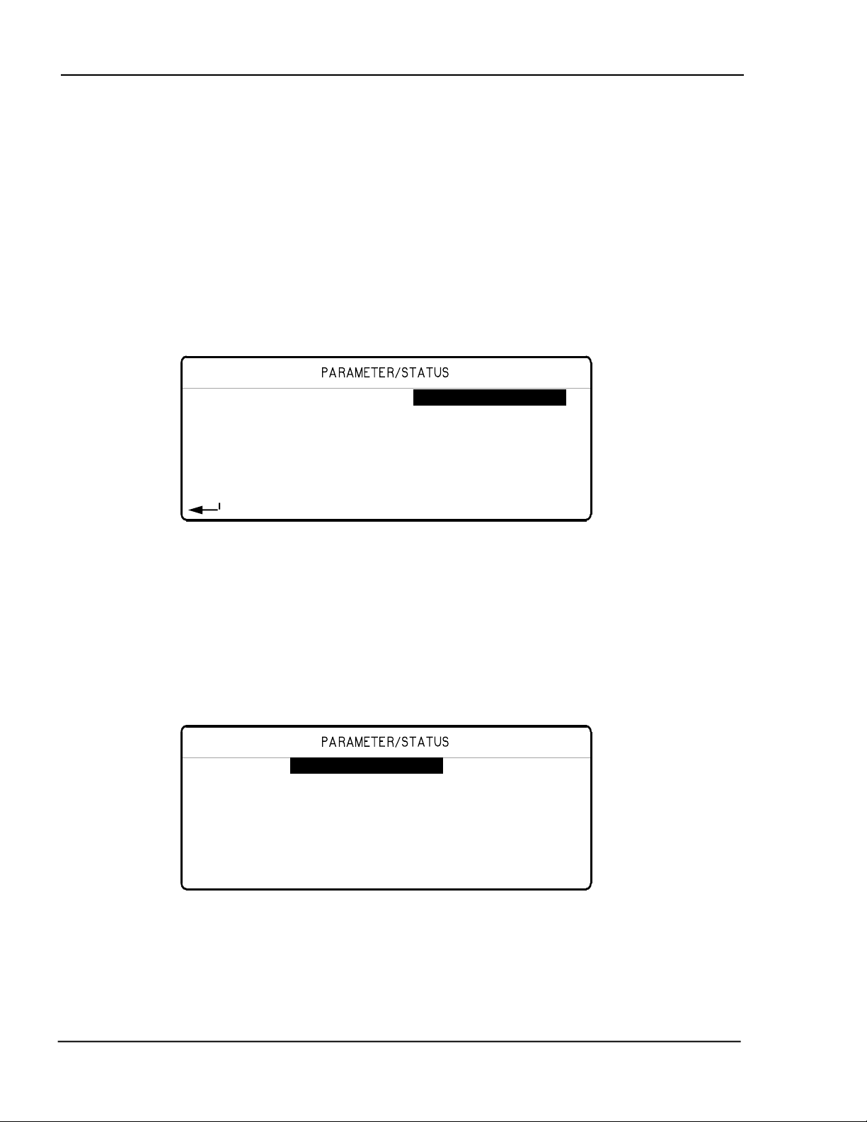
MDC-360C DEPOSITION CONTROLLER
/
while it is in the Predeposit Hold state then one second after it enters the deposit
state, the "Ion Gun Power" output will go true for 180 seconds or three minutes.
4.3.3.4 PROGRAM ACTIONS
The MDC-360C provides for 16 internal user programmable actions. Internal
actions are used to provide special functions at the true evaluation of a condition
string. These functions may be such things as terminating a deposit on an input
from an optical monitor. Or, sounding an alarm when certain events are true.
To program an action, first select the desired action from the list of 16
programmable actions displayed in the Actions screen.
Select Action 01 Hold In State-----
02 Step From State
03 Sound Attention
04 Sound Alert
05 Sound Alarm
06 No Action
07 No Action
- View
Edit 08 No Action
Figure 4-14 Action Selection Screen
Once you have selected the required action, pressing the Right-arrow key will
present the screen which permits programming of the action details, and this
procedure is similar to the one used for programming discrete outputs.
Action Name Hold In State-----
Conditions
Press > to select action
Figure 4-15 Program Action Screen
In this screen you select the predefined action you would like to take and the
associated conditions. To specify an action, move the markers onto the action
name field and press the Right-arrow key. This will present the Select Defined
Action screen.
PROGRAMMING AND CONTROLLER SETUP 4-34
Page 75

MDC-360C DEPOSITION CONTROLLER
Select Defined Action: 01 No Action------ 02 Manual Power
03 Zero Thickness
04 Reset Controller
05 Abort Process
06 Halt Process
07 TerminateDeposit
to select action 08 Hold In State
Figure 4-16 Select Defined Action Screen
In this screen you can select a predefined action from the list by moving the
cursors onto the desired action and pressing Enter. The following is a list of the
predefined actions:
No Action - No action is taken. The default setting.
Manual - Functionally identical to pressing Manual key.
Zero - Functionally identical to pressing Zero key.
Reset - Functionally identical to pressing Reset key.
Abort - Functionally identical to pressing Abort key.
Halt - Halts the process, sets active source power to idle, and leaves all other
source powers unchanged.
Terminate Deposit - Triggers the final thickness for the deposit state. Action is
ignored if state is not a deposit state.
Hold In State - Holds controller in current state.
Step From State - Steps controller to next state.
Sound Attention - Triggers the attention sound and displays the "Attention
Action" message in the State/Trouble field in the Parameter/Status display.
Sound Alert - Triggers the Alert sound and displays the "Alert Action" message
in the State/Trouble field in the Parameter/Status display.
Sound Alarm - Triggers the Alarm sound and displays the message "Alarm
Action" in the State/Trouble field of the Parameter/Status display.
Start Process - Trigger the start of the currently selected process. This action is
ignored unless the controller is in the Process Ready state.
Select Process 1-8 - Select process #1-8 as the next process to be started by the
Start Process action described above.
Switch Crystals - Toggles between the primary and the backup sensor/crystal
combination defined by the active material. The first sensor/crystal will be
PROGRAMMING AND CONTROLLER SETUP 4-35
Page 76

MDC-360C DEPOSITION CONTROLLER
#
switched if more than one sensor/crystal combinations are enabled for
measurement.
Start Timer 1-8 – Resets the corresponding timer to zero and initiates counting.
The timers are used to trigger other actions and/or outputs some time after the
triggering event or for a set amount of time. This is a momentary action meaning
it only triggers once when evaluated as true. The Start Timer’s condition string
must be evaluated as false then true to trigger again.
Set Soft Node 1-8 – Sets a corresponding softnode. Softnodes are used in
condition strings to trigger actions or outputs.
Once an action is selected then you need to establish when the action should take
place by defining its condition string. This is covered in the earlier section called
Entering a Condition String.
4.3.3.5 EDIT SENSOR SETUP
Selecting Edit Sensor Setup will present the Sensor Setup screen shown in Figure
4-17. In this screen you define the sensor parameters that the controller needs to
interface to the various types of sensors. Once the sensor setup is complete, the
controller will create the necessary inputs and outputs needed to interface to the
defined sensors. To define a sensor, first select the sensor number by using the
Up-arrow and Down-arrow keys to highlight the desired sensor number. Once
selected, the sensor is configured by selecting the appropriate parameters from the
right half of the display:
Sensor Setup
Number of Crystals 06
Sensor #1 Shutter Relay Type N.O.
Sensor #2 Control Manual
Sensor #3 Drive Up
Sensor #4 Feedback Type No Feedback
Sensor #5 Rotator Delay(sec) 00
Sensor
6
Figure 4-17 Sensor Setup Screen
1. Number of crystals (1 to 8)
This parameter defines the number of crystals available for that sensor inpu t. For
a single sensor head this would be set to one. For a dual sensor head with
separate oscillators and sensor connections, this would still be set to one because
there is only one crystal for each sensor input. For a multiple rotary type sensor
head, this parameter would be set to the number of crystals that the sensor will
hold.
2. Shutter Relay type (N.O., N.C., None, Dual)
PROGRAMMING AND CONTROLLER SETUP 4-36
Page 77

MDC-360C DEPOSITION CONTROLLER
This parameter defines the shutter relay type used to control the sensor shutter.
The following four relay types are available:
N.O. - Relay is normally open and closes to close shutter. For this type, a
“SensorN Shutter” output will be created to interface to the shutter actuator.
N.C. - Relay is normally closed and opens to close shutter. For this type, a
“SensorN Shutter” output will be created to interface to the shutter actuator.
None - No sensor shutter output is created.
Dual - Select this type for a dual sensor head. For this type, a “Dual Snsr1&2
Shtr” output will be created to interface to the shutter actuator.
3. Control (Manual, Direct, BCD, Indiv)
This parameter defines the type of crystal position control utilized.
Manual, as it implies, means not under control of the MDC-360C. Under manual
control, the MDC-360C will stop the process upon the completion of the current
layer when the next layer requires a different crystal position. A message
prompting the operator with the number of the crystal required is displayed in the
Parameter/Status window. Once the crystal has been changed, the process is
resumed by pressing the Start key.
BCD and Indiv are used when control is through an external crystal rotation
controller which accepts Binary Coded Decimal inputs or Individual switch
closures to select the crystal. The controller creates the number of outputs
required to interface with the external controller and set the outputs as required to
signal a crystal
Direct is used when the actuating device is driven directly. In this case the
controller creates one or two outputs, one for each available direction, to drive a
motor or solenoid.
4. Drive (Up, Down, Fast, Inline, Sngl Step, Dbl Step)
This parameter defines the drive method or direction for Direct control and only
has an effect when Control type is set to Direct. The different settings are
described below.
Up, Down, Fast and Inline - These four settings are typically used with multi-
crystal heads that use a motor to rotate the crystals into position. With Up
selected, the controller will create one output called "SensorN Drive Up". The
MDC-360C will activate this output to increment the sensor head up to the
next position. The down selection works the same except the output is called
"SensorN Drive Dn". With Fast selected, the controller will create both an up
and a down output. The 360C will then determine the fastest direction to the
target crystal position by activating the appropriate output. The Inline drive
type informs the controller that continuous travel in one direction is not
possible. Therefor to get from position 6 to 1, the direction must be down
through 5, 4, etc. until 1 is reached.
SnglStep and Dbl Step - Both the SnglStep and Dbl Step settings are typically
used with multi-crystal sensor heads that are actuated by pulsing a pneumatic
PROGRAMMING AND CONTROLLER SETUP 4-37
Page 78

MDC-360C DEPOSITION CONTROLLER
valve. The MDC-360C will create a "SensorX Drive Up" which is either
singly or doubly pulsed to sequentially step the sensor head to the next
position.
5. Feedback Type (Individual, BCD, Single Home, In Position, No Feedback)
This parameter defines the type of feedback for a multiple sensor head. The three
feedback types available are as follows:
Individual - Individual position feedback. This feedback type uses one input
for each crystal position in the sensor head. All inputs are normally false
(open circuit) unless that crystal is in position then that input is true (closed to
ground). For example, a six crystal sensor head would use six inputs. If
crystal two was in position then all the inputs would be false except the input
connected to feedback position number two.
BCD - Binary Coded Decimal position feedback. This feedback type
uses binary coding to indicate which crystal is in position. Inputs are
numbered most significant bit first. For example, an eight crystal sensor head
would use three inputs. With crystal one in position, all inputs would be false.
With crystal four in position, inputs one and two would be true and input three
would be false.
Crystal
number
Input
BCD2
Input
BCD1
Input
BCD0
1 OPEN OPEN OPEN
2 OPEN OPEN GND
3 OPEN GND OPEN
4 OPEN GND GND
5 GND OPEN OPEN
6 GND OPEN GND
7 GND GND OPEN
8 GND GND GND
Table 4-1 Table of Input states for BCD feedback type
SNGL HOME - Single home position feedback. This feedback type uses one
input. The input is normally false (open circuit) and should go true (closed to
ground) when crystal one is in position.
IN POSITION - In position feedback. This feedback type uses one input.
The input is normally false (open circuit) and should go true (closed to
ground) when the desired crystal is in position.
NO FEEDBACK - No crystal position feedback is used.
PROGRAMMING AND CONTROLLER SETUP 4-38
Page 79

MDC-360C DEPOSITION CONTROLLER
#
6. Rotator Delay (0 to 99 seconds)
This parameter serves two different functions. If the feedback type is “None”
(Not recommended. See cautions in the Installation section.), this parameter tells
the controller how long to wait assuming the crystal is in position. If position
feedback is provided, this parameter tells the controller how long it should wait
for the crystal to reach its target position before it issues a Sensor Fault message.
4.3.3.6 EDIT SOURCE SETUP
Selecting Edit Source Setup will present the Source Setup screen as shown in
Figure 4-18. In this screen you first select the source setup you wish to edit. To
select a source, use the Up-arrow and Down-arrow keys, then press the Rightarrow or Enter key to select.
Source Setup Number of Pockets 01
Shutter Relay Type N.O.
Source #1 Shutter Delay (sec) 0.0
Source #2 Control Direct
Source #3 Drive Up
Source #4 Feedback Type Individual
Source #5 Pocket Delay (sec) 10
Source
6 Source Voltage 10V
Figure 4-18 Source Setup screen
Once selected, the source is configured with the following parameters located on
the right side of the display:
1. Number of Pockets (1 to 16)
This parameter defines the number of pockets, or crucibles, available for the
source. The default value is 1 for a single pocket source.
2. Shutter Relay type (N.O., N.C., None)
This parameter defines the shutter relay type used to control the source shutter.
The following three relay types are available:
N.O. - Relay is normally open and closes to close shutter. For this type, a
“SourceN Shutter” output will be created to interface to the shutter actuator.
N.C. - Relay is normally closed and opens to close shutter. For this type, a
“SourceN Shutter” output will be created to interface to the shutter actuator.
None - No sensor shutter output is created.
3. Shutter Delay (sec) (0.0 to 9.9 seconds)
This parameter should be set to the time it takes for the source shutter to
open/close. At the start of the deposition, the controller will delay adjusting the
power for this amount of time to allow the shutter to completely open. At the end
PROGRAMMING AND CONTROLLER SETUP 4-39
Page 80

MDC-360C DEPOSITION CONTROLLER
of deposition, the controller will begin closing the source shutter this much time
before the target endpoint thickness is reached so the final thickness should be
very close to the target.
4. Control (Manual, Direct, BCD, Indv)
This parameter defines the type of pocket control utilized.
Manual, as it implies, means not under control of the MDC-360C. Under manual
control, the MDC-360C will stop the process upon the completion of the current
layer when the next layer requires a different pocket. A message prompting the
operator with the material required is displayed in the Parameter/Status window.
Once the pocket has been changed, the process is resumed by pressing the Start
key.
BCD and Indv are used when control is through an external pocket rotation
controller which accepts Binary Coded Decimal inputs or Individual switch
closures to select the pocket. The controller creates the number of outputs
required to interface with the external controller and sets the outputs as required
to signal a pocket change.
Direct is used when the actuating device is driven directly. In this case the
controller sets up one or two outputs, one for each available direction, to drive a
motor or solenoid.
5. Drive (Up, Down, Fast, Inline, Sngl Step, Dbl Step)
When the Control type is Direct, this parameter defines the drive method or
direction. For Sngl Step and Dbl Step drive types, the controller sets up one
output which is either singly or doubly pulsed to actuate a solenoid to sequentially
step the rotator to the desired position. For Up and Down drive types, the
controller sets up one output to control a drive motor which is turned on until the
rotator reaches the desired position. For Fast and Inline drive types, the controller
sets up a drive up and a drive down output. For the Fast drive type, the controller
determines the fastest direction to the target pocket position and turns on the
appropriate output. The Inline drive type informs the controller that continuous
travel in one direction is not possible. Therefore to get from position 6 to 1, the
direction must be down through 5, 4, etc. until 1 is reached.
The controller creates one or more of the following outputs depending on the
type:
Drive Up
Drive Down
Step
6. Feedback Type (Individual, BCD, Single Home, In Position, No Feedback)
This parameter defines the type of feedback for a multiple pocket source. The
three feedback types available are as follows:
Individual - Individual position feedback. This feedback type uses one input
for each pocket position in the source. All inputs are normally false (open
PROGRAMMING AND CONTROLLER SETUP 4-40
Page 81

MDC-360C DEPOSITION CONTROLLER
circuit) unless the respective pocket is in position then that input is true
(closed to ground). For example, a six-pocket source would use six inputs. If
pocket two was in position then all the inputs would be false except the input
connected to feedback position number two.
BCD - Binary Coded Decimal position feedback. This feedback type
uses binary coding to indicate the pocket position. Inputs are numbered most
significant bit first. For example, an eight-pocket source would use three
inputs. With pocket one in position, all inputs would be false. With pocket
four in position, inputs one and two would be true and input three would be
false.
SNGL HOME - Single home position feedback. This feedback type uses one
input. The input is normally false (open circuit) and should go true (closed to
ground) when pocket one is in position.
IN POSITION - In position feedback. This feedback type uses one input.
The input is normally false (open circuit) and should go true (closed to
ground) when the desired pocket is in position.
NO FEEDBACK - No pocket position feedback is used.
Pocket
Number
Input
BCD2
Input
BCD1
Input
BCD0
1 OPEN OPEN OPEN
2 OPEN OPEN GND
3 OPEN GND OPEN
4 OPEN GND GND
5 GND OPEN OPEN
6 GND OPEN GND
7 GND GND OPEN
8 GND GND GND
Table 4-2 Table of Input states for BCD feedback type
7. Rotator Delay (0 to 99 seconds)
This parameter serves two different functions. If the feedback type is “None”
(Not recommended. See cautions in the Installation section) this parameter tells
the controller how long to wait, on the assumption the pocket will get into
position. If position feedback is provided, this parameter tells the controller how
long it should wait for the pocket to reach its target position before it issues a
Source Fault message.
8. Source Voltage (2.5V, 5.0V, 10V)
PROGRAMMING AND CONTROLLER SETUP 4-41
Page 82

MDC-360C DEPOSITION CONTROLLER
This parameter sets the upper voltage range for the source control output. The
lower voltage range is always 0. For example, selecting 10 for this parameter sets
the source control voltage range from 0 to 10 volts.
4.3.3.7 EDIT DAC SETUP
Selecting Edit DAC Setup from the Edit System Setup menu will present the
DAC Setup screen that allows selection of the parameter and its signal range for
each of the two DACs.
DAC Setup
DAC Output #1 Rate----DAC Scale #1 3 Digit
DAC Output #2 Power
DAC Scale #2 3 Digit
Figure 4-19 DAC Setup Screen
1. DAC Output (Rate, Rate Dev., Power, Thickness)
One of four system control parameters is chosen for the DAC output. The default
setting is Rate for DAC #1 and Rate Deviation for DAC #2.
2. DAC Scale (2-digit, 3-digit)
Either the two least significant, or the three least significant, digits of the chosen
control parameter are used to represent full scale for the DAC output.
4.3.3.8 EDIT UTILITY SETUP
Selecting the Edit Utility Setup from the Edit System Setup menu will present the
Utility Setup screen. Figure 4-20 shows the first page of this screen. All
parameters are described below.
PROGRAMMING AND CONTROLLER SETUP 4-42
Page 83

MDC-360C DEPOSITION CONTROLLER
Utility Setup
Crystal Frequency 6.0 MHz
Simulate mode On
Interface address 01 (1-32)
Attention Volume 01 (0-10)
Alert Volume 01 (0-10)
Alarm Volume 01 (0-10)
Data Points/min 60 ppm
Figure 4-20 Utility Setup screen
1. Xtal Freq. (2.5, 3.0, 5.0, 6.0, 9.0, 10.0 MHz)
This parameter determines the uncoated crystal frequency type for all sensor
inputs. The default setting is 6.0 MHz.
2. Simulate Mode (On, Off)
This parameter enables or disables the Simulate mode of the controller. The
Simulate mode is used for process testing and differs from the Normal mode only
to the extent that the Thickness and Rate displays are derived from a simulated
sensor input rather that the actual sensor. While in this mode, the simulated
thickness build- up is directly proportional to the displayed power level and
independent of actual thickness on the sensor. The Simulate mode allows the
total deposit process to be simulated. It also allows the tooling factor, density and
acoustic impedance calculations to be conveniently checked and altered at the end
of the run, if necessary.
3. Interface Address. (1-32)
This parameter sets the controller’s computer interface address for the RS-485
and IEEE-488 interfaces.
4. Attention Volume (0-10)
This parameter sets the volume of audio attention sound. Attention sounds
indicate that the controller is waiting for an operator response or action before
continuing the process. A setting of zero disables audio attention sound.
5. Alert Volume (0-10)
This parameter sets the volume of audio alert sound. Alert sounds indicate that a
material alert level has been exceeded. A setting of zero disables audio alert
sounds.
6. Alarm Volume (0-10)
This parameter sets the volume of audio alarm sound. Alarm sounds indicate that
a material alarm level has been exceeded. A setting of zero disables audio alarm
sounds.
PROGRAMMING AND CONTROLLER SETUP 4-43
Page 84

MDC-360C DEPOSITION CONTROLLER
7. Data Points/Min (30,60,120,300,600 PPM)
This parameter sets the number of run-time data point sets per minute that will be
written to the process log. The default is 600 data points/minute. During a
process, data is logged automatically up to 10 data point sets per minute. At this
rate the 27,000 data point storage can hold 45 minutes of data. To allow for
longer processes, you can change the number of data point sets stored per minute.
The following table shows the approximate storage time based on the number of
data points per minute parameter. Press the ‘Enter’ key to cycle between options.
This parameter is only visible when the data logging option is installed.
Data Points/Minute Approx. Storage Time
(minutes)
30 900
60 450
120 225
300 90
600 45
8. Time (00:00-23:59)
This parameter sets the system time. Time is entered in 24-hour format without a
digit separator “:”. For example, to enter 1:05 PM you must enter “1305”. This
parameter is only visible when the data logging option is installed.
9. Date (01/01/00-12/31/99)
This parameter sets the system date in month/day/year format. The complete date
must be entered without the digit separator “/” character, and with two digits for
each of the month, day and year. For example, to enter 5/2/94, you must enter
“050294”. This parameter is only visible when the data logging option is installed.
PROGRAMMING AND CONTROLLER SETUP 4-44
Page 85

MDC-360C DEPOSITION CONTROLLER
5. OPERATING THE MDC-360C
5.1 SIGN-ON SCREEN
At power-on the Parameter/Status display will present a screen which details the
controller configuration, and all LEDs will be illuminated. The figure below
shows the configuration for a basic MDC-360C with a single Source/Sensor card,
a single Discrete I/O card and an RS-232 interface installed. Please refer to
Sections 2, 3 and 4 for a detailed description of the MDC-360C resources and
how to use them before attempting to operate the controller.
At this point, with the sign-on configuration information on the LCD screen and
all LED’s illuminated, pressing any key momentarily will put the controller into
the Abort mode. Within the illuminated keypad group, only the red LED behind
the Abort key pad will now be illuminated. Each digit position of the process-run
numerical LEDs will contain a 0-9 value. The information displayed by the LCD
screen will depend on what was being displayed when power to the controller was
last turned off.
Press the Reset key to put the controller into the Reset state in preparation for a
process-run.
INFICON MDC-360c Software Version x.x
Source/Sensors Cards 1 Installed
Discrete I/O Cards 1 Installed
RS-232 Computer Interface Installed
Data Log Storage Not Installed
Press any key to continue.
Figure 5-1 Sign-on screen
5.2 STARTING A NEW PROCESS
Pressing the Start key while the controller is in the Ready state will present the
screen shown below. A run number is provided to help correlate process
information with a specific process run. The run number can range from 1 to
9999. It is incremented at the start of each process. At 10,000 the run number
will roll over to 1.
OPERATING THE MDC-360C
5-1
Page 86

MDC-360C DEPOSITION CONTROLLER
Start Process 01 Sample----- 02
Starting Layer: 001 03
Run Number : 0001 04
05
06
Press Start to start 07
or Reset to cancel. 08
Figure 5-2 Run Process Selection Screen
From this screen you can change the starting layer number and run number, if
required, using the arrow keys to position the edit cursors, and can then select the
process to start by positioning the cursors on the desired process name, which
then becomes the ‘current’ process. To actually start the process, just press the
Start key again. The controller will then scan the total process definition and the
condition of the system, and if everything appears to be in order will start the
process.
If at this point an error message is presented by the LCD screen, it is likely that
there is a problem somewhere with either the system configuration and/or the
value of a system parameter which will prevent the process from running
correctly. Use the details of the error message as an indication of the corrective
action that should be taken. Press the Abort key to abort the process start, then
the Reset key, and then make the necessary changes.
5.3 STARTING A NEW LAYER
The Start key is also used to start individual layers when the controller is set up
for manual layer sequencing. The controller will prompt the operator to press the
Start key to start the next layer.
5.4 RESUMING AN ABORTED OR HALTED PROCESS
The Start key is also used to resume an aborted or halted process. Pressing the
Start key while the controller is in abort or halt mode will bring up the following
prompt. Note that the green LED behind the Start key is illuminated, indicating
that the process can be resumed. Otherwise, the controller has to be reset, and the
process has to be started over.
Press Start to resume process
or Reset to cancel.
Follow the prompt to resume the process.
OPERATING THE MDC-360C 5-2
Page 87
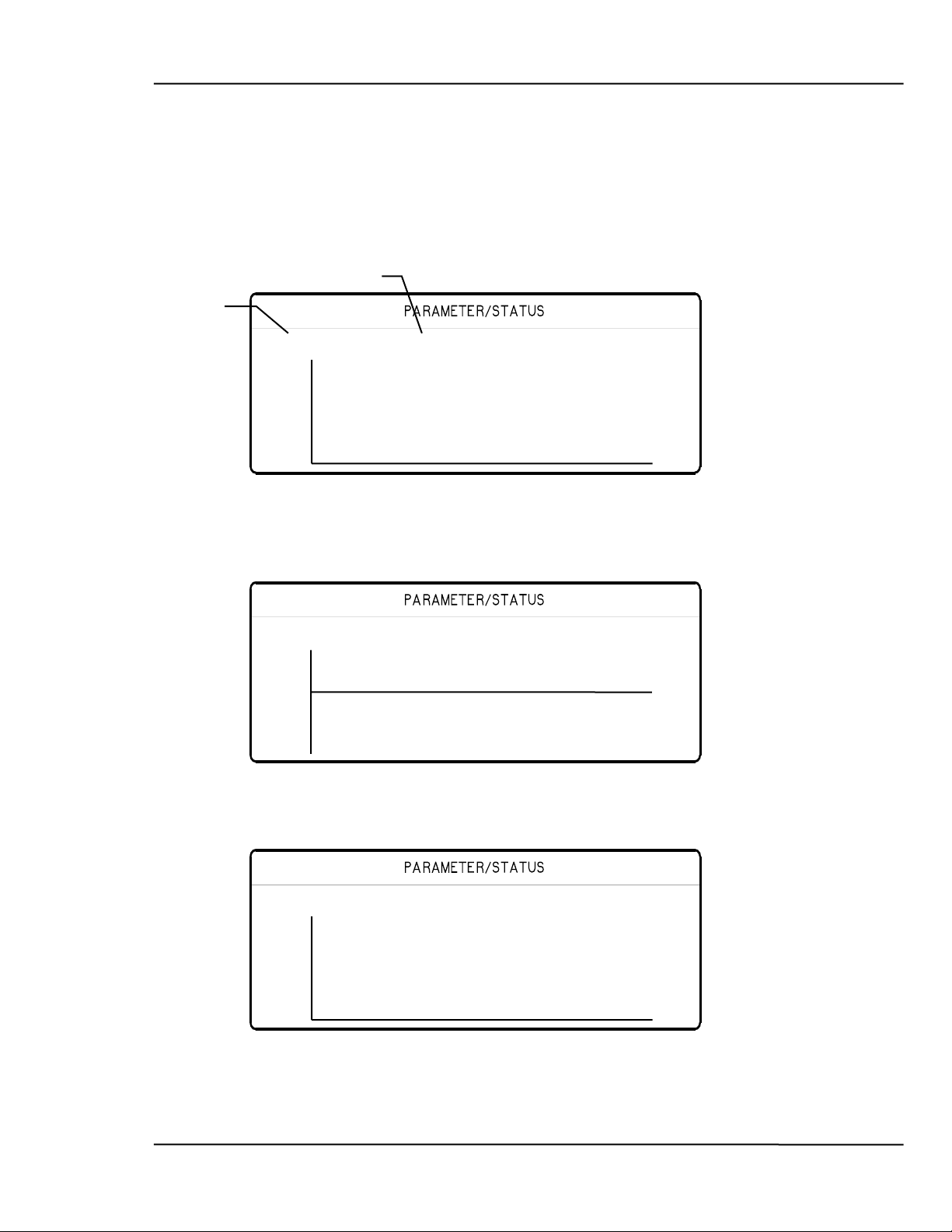
MDC-360C DEPOSITION CONTROLLER
5.5 GRAPH DISPLAYS
There are four different run time graph screens that can be displayed at any time
by pressing the Graph key (providing they have each been enabled in the Edit
Display Setup menu). The first key press will bring up the last viewed graph
screen, repeatedly pressing the Graph key will cycle through the four graph
screens, shown below.
Displays the current
process name.
Displays the current
material name.
Sample Cr Process Ready
10 Rate
0 1
Figure 5-3 Rate vs. Time Graph
Sample Cr Process Ready
5 Rate Dev%
5
1
Figure 5-4 Rate Deviation vs. Time graph
Sample Cr Process Ready
999 Thickness
0 1
Figure 5-5 Thickness vs. Time Graph
OPERATING THE MDC-360C
5-3
Page 88
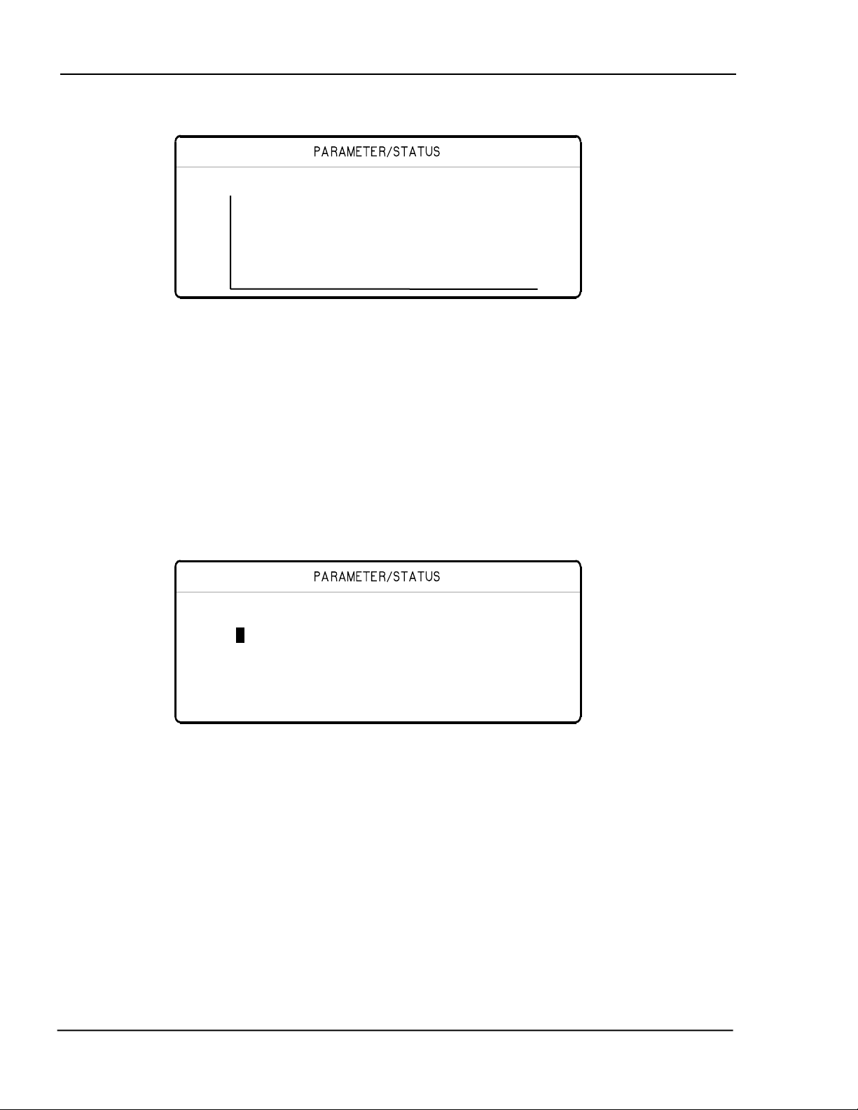
MDC-360C DEPOSITION CONTROLLER
Sample Cr Process Ready
10 Power%
0 1
Figure 5-6 Power vs. Time Graph
5.6 STATUS DISPLAYS
There are two run time status screens that can be displayed at any time by
pressing the Status key (providing they have each been enabled in the Edit
Display Setup menu). The first key press will bring up the last viewed status
screen, repeatedly pressing the Status key will cycle through the two status
screens, shown below.
Sample Cr Process Ready
Src Pckt Power Snsr Xtl Hlth Rate Thick
1* 1 23.7 1* 1 95 00.0 0.000
2 10.0 2 99 00.0 0.000
3 00.0 3 -- 00.0 0.000
4 00.0 4 -- 00.0 0.000
5 00.0 5 -- 00.0 0.000
6 00.0 6 -- 00.0 0.000
Figure 5-7 Source/Sensor Status screen
The Source/Sensor status screen displays the status of the six sensors and sources
including the crystal or pocket position, source power, crystal health, each
sensor's deposition rate and thickness or frequency. You select either sensor
thickness or frequency in the Edit Display Setup Menu by setting the Sensor
Status parameter. Active sources and the active sensors are indicated with an *
next to the number. A failed sensor/crystal is indicated by “--” in the health field.
The Source/Sensor Status Screen also allows the user to change the source pocket
position, sensor crystal position and the active sensor. You can only change the
source pocket and sensor crystal positions if the MDC-360C is setup for
automatic control. The source pocket position can only be changed while the
MDC-360C is in the Ready mode. To change a source pocket number, simply
move the cursor onto the pocket number of the desired source, enter the new
OPERATING THE MDC-360C 5-4
Page 89

MDC-360C DEPOSITION CONTROLLER
pocket number and press Enter. The MDC-360C will enter the Change Pocket
State where it will remain until the desired pocket is in position or a Source Fault
occurs.
You change the sensor crystal position by moving the cursor onto the crystal
number of the desired sensor, enter the new crystal number and press Enter. The
MDC-360C will enter the Change Crystal State where it will remain until the
desired crystal is in position or a Sensor Fault occurs.
You change the active sensor by moving onto the current active sensor, enter the
new sensor number and press Enter. The active sensor as indicated by the * will
change to the selected sensor.
Sample Cr Process Ready
Input State Output State
01 Name F F
02 F F
03 F F
04 F F
05 F F
06 F F
Figure 5-8 I/O Status Screen
The I/O status screen indicates the state of all the MDC-360C's inputs and
outputs. Please note that you can use the arrow keys to scroll up and down the
I/O listing.
5.7 VIEWING RESULTS
The MDC-360C has an optional Internal Data Storage capability that provides
internal storage of real time run data. Stored data can later be viewed through the
four status graphs or can be downloaded to a PC for permanent storage and/or
review.
The data log option provides storage for up to 16 process logs and/or 27,000 data
point sets of real time run data. A process log consists of the process name, run
number, starting time and date, ending time and the completion status of the run.
The process logs are stored in a stack such that newest process is at the top of the
stack and the oldest process is at the bottom of the stack. The start of the next
process will push all of the logs down one position on the stack. The last or 16th
process log on the stack will be lost.
A data point set consists of the measured deposit rate, rate deviation, thickness
and the deposit power. The 27,000 data point sets are stored in a circular buffer
such that new data will overwrite the oldest data. If data from the current process
overwrites an older process than that entire process will be erased. If data from
the current process tries to overwrite the start of the current process then data
logging is stopped so that the beginning of the process is saved.
OPERATING THE MDC-360C
5-5
Page 90
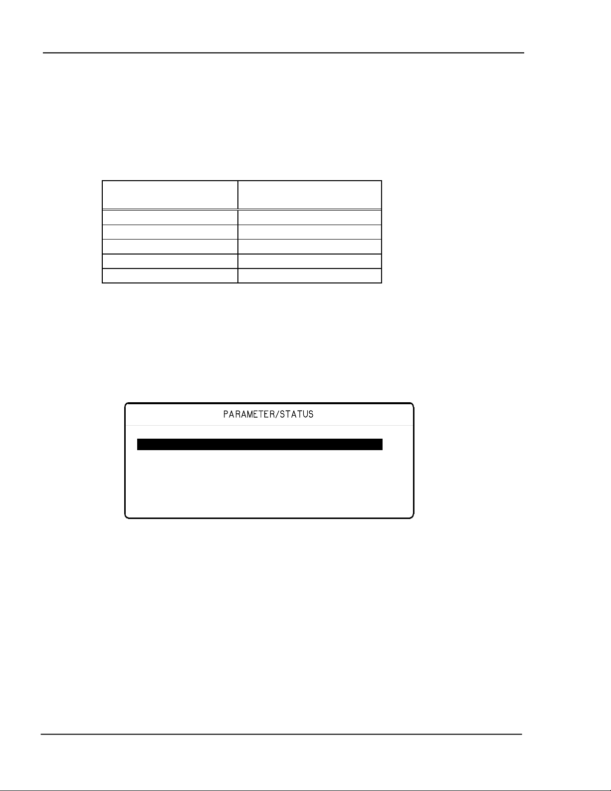
MDC-360C DEPOSITION CONTROLLER
During a process, data is logged automatically up to 10 data point sets per minute.
At this rate the 27,000 data point storage can hold 45 minutes of data. To allow
for longer processes, the user has the ability to change the number of data point
sets stored per minute. The parameter to modify is called Data Points/Min and
can be found in the Utility Setup menu. The following table shows the total
storage time based on the number of data points per minute parameter.
Data Points/Minute Approx. Storage Time
(minutes)
30 900
60 450
120 225
300 90
600 45
To view a stored process log, select the View Results option from the Main Menu.
This will present a screen with the process log shown in Figure 5-9. From this
screen any of the 16 process logs can be selected for viewing. Note that this
screen is only available if the Internal Data Storage and Time/Date Clock option
installed.
Process Name Run# Time Date Status
Sample 0002 12:05 12/28/94 Normal--
Sample 0001 09:54 01/23/95 Aborted
Figure 5-9 View Results Screen
This screen displays the process name, run number, starting time and date and the
status. The status can be either running, normal, aborted or overrun. Overrun
means that this process overran itself within the data store.
To select a process log for viewing, just move the cursors onto the desired process
and press the Enter or the Right-arrow key. Please note that you cannot view a
process log while in process.
Once a process has been selected, the screen will change to the rate vs. time graph
shown in Figure 5-10. The logged data will be plotted for the first layer of the
process. Plotting the data may take from 5 seconds for short layer to up to 15
seconds or more for long layers with a lot of data. Please note that while the data
is being plotted the controller will not read any key presses. When the data has
OPERATING THE MDC-360C 5-6
Page 91

MDC-360C DEPOSITION CONTROLLER
y
y
y
g
been plotted the layer number will be displayed in the upper right hand corner of
the screen. At this point you can press the Status key to switch between the four
graphs. You can also enter a different layer number to view another layer.
Displays the current
process name.
Displays the current
er material name.
la
Sample Cr Lyr 001 (001-999)
10 Rate
0 1
Displays the current
er number.
la
Displays the process
er ran
la
e.
Figure 5-10 Rate vs. Time Process Log Graph
To return to the process log, press the Left-arrow key.
5.8 MODES
Modes are conditions that the controller can occupy. Some modes are indicated
by the LED’s behind the operating keys. Other modes are displayed in the top
right hand corner of the status display (Refer to Figure 5-3). These controller
modes are described below.
5.8.1 PROCESS READY
The Process Ready Mode indicates the MDC-360C has been reset and is awaiting
a Start key press. The yellow LED behind the Reset key, when illuminated,
indicates that the controller is in Process Ready Mode.
5.8.2 ABORT
The Abort mode is indicated by a red LED behind the Abort key as well as the
flashing of all of the numeric LED displays. In Abort Mode all displays and
operating keys, with the exception of the Start and Reset keys, are inoperative.
All source control outputs are forced to zero, the Abort relay is closed and all
discrete outputs are forced to open circuit. In addition, if the controller initiated
the abort then the condition which caused the abort will be displayed in the top
right hand corner of the Parameter/Status display. Exit from Abort Mode requires
either a Reset or Start key press. See also Section 5.4 for resuming an aborted
process. Refer to Table 5-1 for conditions that can cause an abort.
OPERATING THE MDC-360C
5-7
Page 92

MDC-360C DEPOSITION CONTROLLER
5.8.3 HALT (SOFT ABORT)
In Halt all I/O is frozen. If power is above Soak level, it is ramped down to Soak
at the Predeposit ramp rate. If Power is at or below the Soak level it is held
constant. The user has the option to resume from Halt or press Reset and start
over. See also Section 5.4 for resuming a halted process. Refer to Table 5-1 for
conditions that can cause the process to halt.
5.8.4 IN PROCESS
The green LED behind the Start key indicates the controller is in the In-Process
Mode.
5.8.5 NOT SAMPLING
This mode indicates that the sensor crystal is shuttered from the source and that
the deposition rate is established using the last power level. Sampling mode is set
by two material parameters, Sample Dwell % and Sample Period. Refer to
Section 4.3.2.1 # 44 and # 45 for a description of Sample Mode.
5.8.6 PROCESS COMPLETE
This mode indicates that the selected process has run to completion. A Process
Complete message is displayed in the top right hand corner of the status display.
In addition, an attention warning will sound. The controller remains in this mode
until a reset signal puts it into the Process Ready mode.
5.8.7 MANUAL
This mode is indicated by the red LED behind the Manual key. In this mode the
control voltage output is controlled through the Remote Power Handset. For a
detailed description of this mode, refer to Section 3.5.
5.8.8 SIMULATE
This mode simulates rate and thickness build-up by simulating the sensor input
rather than the actual sensor. Refer to Section 3.4 for more information on the
Simulate Mode.
5.9 STATES
Figure 5-11 shows the different states that make up a complete deposition cycle,
such as Rise to Soak, Rise to Predeposit, etc. The controller moves from state to
state as the deposition progresses.
5.10 TROUBLE, ERROR AND WARNING MESSAGES
Troubles are controller conditions which in most case are indicative of problems
or errors, but may be just warnings. These messages are displayed in the top right
hand corner of the status screen (See Figure 5-3).
In addition, there are three levels of audible warnings associated with the trouble
conditions, Attention, Alert and Alarm. Table 5-1 lists the messages and warning
OPERATING THE MDC-360C 5-8
Page 93

MDC-360C DEPOSITION CONTROLLER
levels. The list is arranged in descending order of priority. In the event that more
than one warning level is triggered, the higher level has priority. An asterisk in
the Clear column indicates the warning sound will clear when the condition
clears. Any key press will also clear the sound. The action column indicates
what if any action is taken as a result of the trouble.
Warning
Messages Type Clear Action
Min Rate&Max Power Alarm Abort
Max Rate&Min Power Alarm Abort
System Setup memory corrupted Alarm Halt
Process memory corrupted Alarm Halt
Material memory corrupted Alarm Halt
Rate Est. Error Alarm Halt
Crystal Failure Alarm/Attn NO/* Halt
Source Fault Alarm Halt
Sensor Fault Alarm Halt
No Snsrs Enabled Alarm Halt
Time Power Alarm Time/Power
Rate Dev. Alarm Alarm *
Alarm Action Alarm
Crystal Marginal Alert/Attn NO/*
Rate Dev. Alert Alert *
Max power Alert Alert *
Min power Alert Alert *
Alert Action Alert *
Xtal Fail Switch Attention Crystal
Switch
Xtal Mrgn Switch Attention Crystal
Switch
Rate Dev. Atten Attention *
Max power Attention *
Min power Attention *
Change source # X to (material name)
Attention Hold
and press Start to continue.
Change sensor # X to crystal # X
Attention Hold
and press Start to continue.
Attention Action Attention *
Press Start to resume process. N/A
Start to continue. Attention * Hold
Calibration Done Attention *
Table 5-1 Trouble Conditions and Warnings
5.10.1 DESCRIPTION
Each of the messages is described below.
OPERATING THE MDC-360C
5-9
Page 94

MDC-360C DEPOSITION CONTROLLER
5.10.1.1 MIN RATE&MAX POWER
This message indicates that the output power is at the maximum power level set
by the Maximum Power parameter and the rate deviation is below the limit value
set in the Rate Dev. Alarm parameter. When this happens, the controller will go
into the Abort mode and the Alarm will sound.
5.10.1.2 MAX RATE&MIN POWER
This message indicates that the output power is at the minimum power level set
by the Minimum Power parameter, and the rate deviation is above the limit value
set by the Rate Dev. Abort parameter. When this happens, the controller will go
in Abort mode and the Alarm warning will sound.
5.10.1.3 SYSTEM SETUP MEMORY CORRUPTED
The integrity of the System Setup Memory has changed since the last time a
system parameter was modified. Each one of the sub menus and its parameters
has to be checked and corrected as necessary to fix this problem.
5.10.1.4 PROCESS MEMORY CORRUPTED
The integrity of the selected process has been changed since last time the process
was modified. Each one of the process parameters has to be checked and
corrected as necessary to fix this problem.
5.10.1.5 MATERIAL MEMORY CORRUPTED
The integrity of the selected material has been changed since last time the
material was modified. Each one of the material parameters has to be checked
and corrected as necessary to fix this problem.
5.10.1.6 RATE EST. ERROR
The controller is unable to establish the programmed rate within the time
specified in the Rate Establish Time parameter. The rate is considered established
when it stays within the Rate Establish Error % for 5 seconds.
5.10.1.7 CRYSTAL FAILURE
This condition indicates lack of a valid signal from the sensor, and generally
results from a failed crystal but may also indicate problems in the crystal
mounting or the interconnection between the sensor and the controller. If the
primary crystal fails and the process is not in deposit state, the Attention warning
will sound. If the backup crystal fails and the process is not in the deposit state,
the alarm will sound and the process will be halted.
5.10.1.8 SOURCE FAULT
This condition indicates that the correct source pocket position feedback has not
been achieved within the time set by the Rotator Delay parameter (Source Setup
Menu).
OPERATING THE MDC-360C 5-10
Page 95

MDC-360C DEPOSITION CONTROLLER
5.10.1.9 SENSOR FAULT
This condition indicates that the correct crystal position feedback has not been
achieved within the time set by the Rotator Delay parameter (Sensor Setup
Menu).
5.10.1.10 NO SENSORS ENABLED
This condition indicates that no sensors were enabled for measurement of this
material.
5.10.1.11 TIME POWER
This message is displayed when the controller is completing the current layer
based on the last power and rate. This occurs in the event of a crystal failure
without a backup.
5.10.1.12 RATE DEV. ALARM
The deposition rate error is greater than the rate deviation value set in the Rate
Deviation Alarm parameter.
5.10.1.13 ALARM ACTION
This message indicates the Alarm sound was initiated by an internal action.
5.10.1.14 CRYSTAL MARGINAL
The sensor crystal in use is poor in quality. If the crystal is the backup one, the
Alert warning will sound when the process is in deposit state. If the primary
crystal is in poor quality then the Attention will sound.
5.10.1.15 RATE DEV. ALERT
The deposition rate deviation is greater than the value set in the Rate Deviation
Alert parameter.
5.10.1.16 MAX POWER ALERT
Indicates that the power output level has been at the Maximum Power level longer
than the time period set in the Power Alert Delay parameter.
5.10.1.17 MIN POWER ALERT
Indicates that the power output level has been at or below the Minimum Power
level longer than the time period set in the Power Alert Delay parameter.
5.10.1.18 ALERT ACTION
This message indicates the Alert sound was initiated by an internal action.
OPERATING THE MDC-360C
5-11
Page 96

MDC-360C DEPOSITION CONTROLLER
5.10.1.19 XTAL FAIL SWITCH
This message indicates the primary crystal has failed and the sensor input has
been switched to the backup crystal. In addition, the Attention warning sounds.
Press any key to clear the sound.
5.10.1.20 XTAL MRGN SWITCH
This message indicates the primary crystal is marginal and the sensor input has
been switched to the backup crystal. In addition, the Attention warning sounds.
Press any key to clear the sound.
5.10.1.21 RATE DEV. ATTEN
The deposition rate deviation error is greater than the value set in the Rate
Deviation Attention parameter.
5.10.1.22 MAXIMUM POWER
The output power is being limited by the value set in the Maximum Power
parameter.
5.10.1.23 MINIMUM POWER
The output power is at or below the minimum power set by the Minimum Power
parameter.
5.10.1.24 CHANGE POCKET...
Prompts the operator to switch the source pocket to the correct position. The
process will be on hold until the Start key is pressed. There is no message if the
Control parameter is set to Auto (Source Setup Menu).
5.10.1.25 CHANGE CRYSTAL...
Prompts the operator to switch the sensor to the correct crystal position. The
process will be on hold until the Start key is pressed. There is no message if the
Control parameter is set to Auto (Sensor Setup Menu).
5.10.1.26 ATTENTION ACTION
This message indicates the Alert sound was initiated by an internal action.
5.10.1.27 CALIBRATION DONE
This message indicates that the sensor tooling factor calibration run initiated by
the user is now complete. The next step is to measure the substrate's actual
thickness using another measuring device such as a profilometer and entered the
measured thickness. The MDC-360C will calculate the tooling factors for all
sensors enabled during calibration based on the each sensor's thickness and the
measure substrate thickness.
OPERATING THE MDC-360C 5-12
Page 97
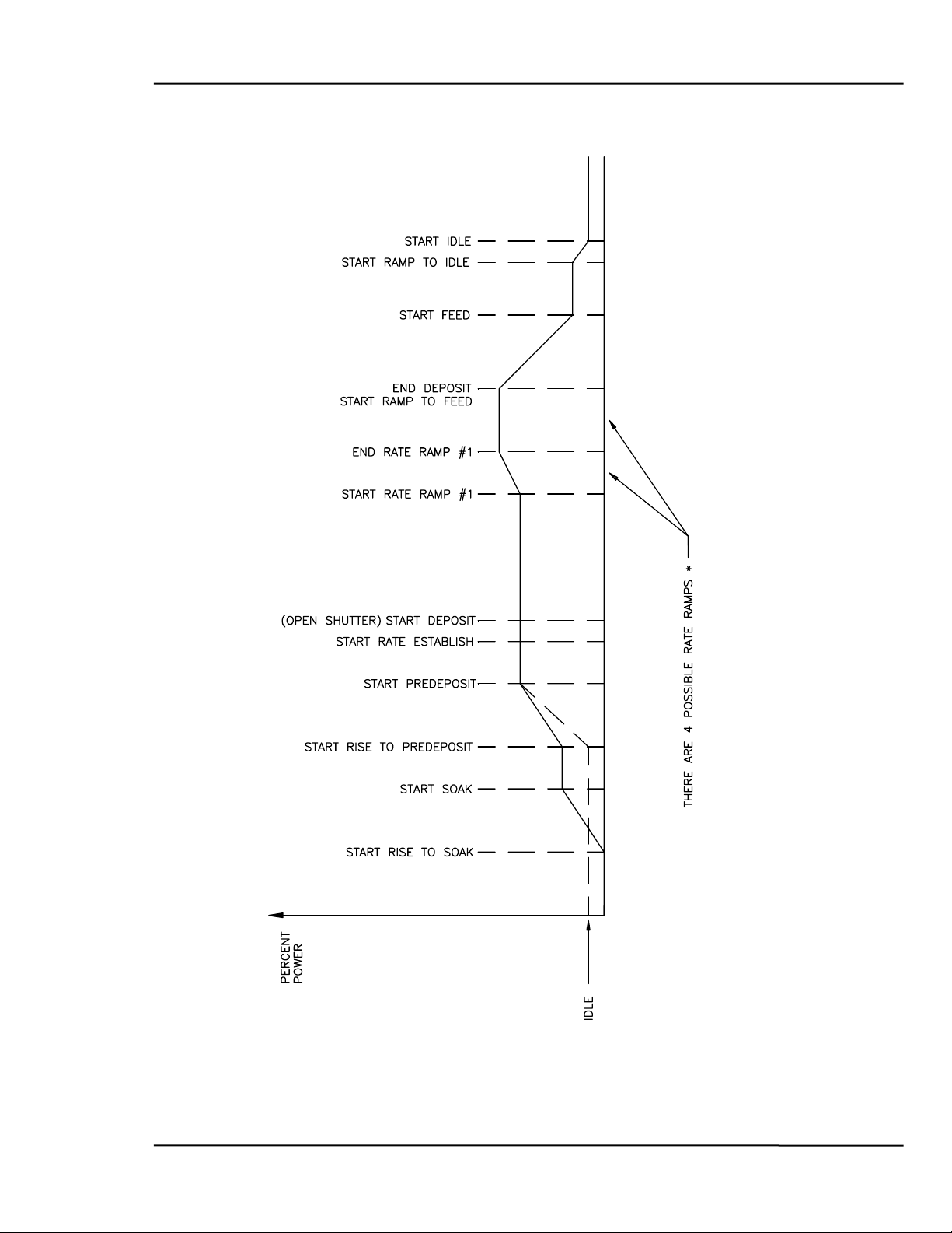
MDC-360C DEPOSITION CONTROLLER
Figure 5-11 Typical Process Profile
OPERATING THE MDC-360C
5-13
Page 98

Page 99

MDC-360C DEPOSITION CONTROLLER
6. TUNING THE MDC-360C CONTROL LOOP
6.1 Control Loop Basics
If evaporation rate were a function of source power alone, a rate controller would
not be necessary. One would establish the power required to achieve the desired
rate, set the power at that point and that would be that. In control system
parlance, this is called “Open Loop” control.
Unfortunately, evaporation rate is a function of many variables. With E-gun
sources, rate is affected by material level, water-cooling temperature, beam
position, sweep pattern, etc. With filaments and boats, rate is affected by material
level, boat or filament condition, power line voltage, power losses in cables,
connections, transformers, switches, etc. Even when sputtering under the
conditions of constant power and constant pressure, rate is affected by target
condition.
So, if we want to achieve a known and constant rate, we need a rate controller.
The rate controller compares the measured rate with the desired rate and attempts
to keep them equal by adjusting the command signal to the power supply. This is
called “Closed Loop” or feedback control.
The most common example of feedback control is a car and driver. The car is the
“Plant”. It is controlled by pedal pressure and steering wheel angle. Its output is
direction and speed. The driver is the “Controller”. The driver monitors the
direction and speed and adjusts pedal pressure and steering wheel angle to achieve
the direction and speed he/she desires. If we hold the controls steady and close
our eyes, no feedback, then our control is open loop. If the road is very straight
and there is no wind, “no disturbances to the plant”, we can sometimes stay on the
road for a pretty good distance. If the road is rolling or we have a good
crosswind, the time we can stay on the road in open loop control can be pretty
short indeed.
If the controller is slow and sluggish, i.e. a drunk driver, the difference between
the desired speed and direction can be very different from the speed and direction
desired. The driver can be all over the road, speeding up, slowing down, etc.
If the controller’s gain is too high, typical of a young person’s first driving
experience, the response to an error is both slow and too great and the car careens
from one side of the road to the other. This control “System” would normally go
completely unstable and crash if control were not assumed by a different
controller.
In the case of a young driver with a little more experience under his/her belt, the
response speed has improved but the gain is still a little high. The vehicle stays
pretty well in control but there is a lot of steering wheel action. We say this
controller is “oversteering”.
When we go from one vehicle to another, especially if the vehicles are very
different in size or weight, we find that we must really concentrate on our driving
at first. That is because we are learning the characteristics of the “Plant”. As
Tuning the MDC-360C Control Loop
6-1
Page 100

MDC-360C DEPOSITION CONTROLLER
soon as we’ve learned them, we know what we have to do to correct for errors
and we are back in good control. In other words the controller must compensate
for the characteristics or the “Plant”.
6.2 CONTROL LOOPS APPLIED TO VACUUM DEPOSITION
In the deposition control loop the vacuum system and evaporation supply make up
the plant. The output, deposition rate, is controlled by the source control voltage
which establishes the source power. If all plants were the same we could
predefine the characteristics of the controller for optimum control. Unfortunately,
plants vary widely, in their gain, linearity, response, noise and drift.
The question we are going to address here is how the controller adjusts the source
control voltage, the “command signal”. The MDC utilizes a type 1 control loop.
A type 1 control loop does not require a continuous error to achieve a non zero
control voltage.
Many controllers utilize a type 0 control loop. In this type of loop the source
control voltage output is determined by multiplying the rate error by the
Proportional gain. For any given non zero output the error required to achieve the
necessary output is inversely proportional the to gain. High gain, low error, low
gain, high error. This would seem to call for high gain. Unfortunately, the higher
the gain the higher the chance of instability. We may go unstable before we get
the error down to where we want it.
In the MDC, the proportional gain parameter sets the rate at which the control
voltage changes in response to an error signal. Any error in the rate causes the
source control voltage to ramp to a new value. When the source control voltage
increases or decreases to the correct value, the value required to achieve the
desired rate, the error goes to zero and the output remains constant.
The Derivative Time constant is utilized to compensate for slow sources such as
boats and induction heated sources. Like a large truck, these sources take time to
get up to speed and to stop. The Derivative Time constant looks at the rate of
change of the error. If the error is decreasing rapidly we better take our foot off
the gas or we are going to overshoot our target. If the error is decreasing, but
decreasing very slowly, we need to goose it to get up to speed. The Derivative
Time constant instructs the controller on how much attention to pay to the rate of
change of the error. A value of zero tells the controller to ignore the rate of
change of the error. A large value tells the controller that this source is slow and
is going to be hard to get going and hard to stop. So if the rate starts to fall off,
give it power, or if we’re quickly approaching the target, begin to decrease the
power.
The Integral Time constant is used to keep the thickness profile on schedule. We
may have no rate error right now, so if we were not concerned about the thickness
profile, we would be happy and leave everything as it is. However if we are
trying to stay on a thickness profile, stay on schedule as it were, we may want to
speed up or slow down a little bit to make up for previously lost, or gained time.
For example, suppose our desired speed is 50 mph and that’s the speed we are
traveling. However we’ve been traveling for exactly an hour and we’ve only
Tuning the MDC-360C Control Loop 6-2
 Loading...