

Page 1
OPERATION AND SERVICE MANUAL
MODEL MDC-360
MAXTEK FILM DEPOSITION CONTROLLER
P/N 179800
S/N _____________
MAXTEK, INC.
http://www.maxtekinc.com
5980 Lakeshore Drive, Cypress, CA 90630-3371
Tel: (714) 828-4200 • Fax: (714) 828-4443
Email: sales@maxtekinc.com • support@maxtekinc.com
Page 2

© 1995-2002 MAXTEK, INC. All rights reserved.
First Edition, March 1995
Second Edition, Revision A, March 1996
Revision B, June 1996
Revision C, December 1996
Revision D, February 1997
Revision E, January 1998
Revision F, March 1998
Revision G, May 1998
Revision H, January 1999
Revision I, November 1999
Revision J, February 2000
Revision K, August 2000
Revision L, October 2002
Revision M, November 2002
Revision N, June 2005
ii
Page 3

WARRANTY
Maxtek, Inc. warrants the product to be free of functional defects in material and
workmanship and that it will perform in accordance with its published
specification for a period of (twenty-four) 24 months.
The foregoing warranty is subject to the condition that the product be properly
operated in accordance with instructions provided by Maxtek, Inc. or has not been
subjected to improper installation or abuse, misuse, negligence, accident,
corrosion, or damage during shipment.
Purchaser's sole and exclusive remedy under the above warranty is limited to, at
Maxtek's option, repair or replacement of defective equipment or return to
purchaser of the original purchase price. Transportation charges must be prepaid
and upon examination by Maxtek the equipment must be found not to comply
with the above warranty. In the event that Maxtek elects to refund the purchase
price, the equipment shall be the property of Maxtek.
This warranty is in lieu of all other warranties, expressed or implied and
constitutes fulfillment of all of Maxtek's liabilities to the purchaser. Maxtek does
not warrant that the product can be used for any particular purpose other than that
covered by the applicable specifications. Maxtek assumes no liability in any
event, for consequential damages, for anticipated or lost profits, incidental
damage of loss of time or other losses incurred by the purchaser or third party in
connection with products covered by this warranty or otherwise.
DISCLOSURE
The disclosure of this information is to assist owners of Maxtek equipment to
properly operate and maintain their equipment, and does not constitute the release
of rights thereof. Reproduction of this information and equipment described
herein is prohibited without prior written consent from Maxtek, Inc.,
5980 Lakeshore Drive, Cypress, California, 90630-3371.
SAFETY
All standard safety procedures associated with the safe handling of
electrical equipment must be observed. Always disconnect power when
working inside the controller. Only properly trained personnel should
attempt to service the instrument.
iii
Page 4

Table of Contents
1. GENERAL DESCRIPTION.............................................................................................1-1
1.1 PURPOSE....................................................................................................................... 1-1
1.2 FEATURES .................................................................................................................... 1-1
1.2.1 EXTENSIVE PROGRAM STORAGE ......................................................................... 1-1
1.2.2 DYNAMIC MEASUREMENT UPDATE RATE.......................................................... 1-1
1.2.3 SUPERIOR GRAPHICS DISPLAY ............................................................................ 1-1
1.2.4 PROGRAM SECURITY.............................................................................................. 1-1
1.2.5 DESIGNED FOR UNATTENDED OPERATION......................................................1-1
1.2.6 FAIL SAFE ABORTS..................................................................................................1-1
1.2.7 ABOR T STATUS RETENTION .................................................................................. 1-2
1.2.8 RUN COMPLETION ON CRYSTAL FAILURE.........................................................1-2
1.2.9 POWER FU L SYSTEM INTERFACE.......................................................................... 1-2
1.2.10 POWER SUPPLY NOISE TOLERANCE............................................................... 1-2
1.2.11 INTERNATIONAL STANDARD POWER CONNECTOR ..................................... 1-2
1.2.12 FIEL D UPGRADABLE.........................................................................................1-2
1.3 SPECIFICATIONS......................................................................................................... 1-3
1.3.1 MEASUREMENT.......................................................................................................1-3
1.3.2 DISPLAY....................................................................................................................1-3
1.3.3 COMMUNICATION...................................................................................................1-3
1.3.4 PROGRAM STORAGE CAPACITY ........................................................................... 1-3
1.3.5 PROCESS PARAMETERS ......................................................................................... 1-3
1.3.6 MATER IAL P ARAMETERS ....................................................................................... 1-3
1.3.7 INPUT/OUTPUT CAPABILITY................................................................................. 1-5
1.3.8 SENSOR PARAMETERS............................................................................................ 1-5
1.3.9 SOURCE PARAMETERS...........................................................................................1-5
1.3.10 RECOR DER P ARAMETERS.................................................................................1-6
1.3.11 UTILITY SETUP PARAMETER............................................................................ 1-6
1.3.12 OTHER.................................................................................................................. 1-6
1.4 ACCESSORIES..............................................................................................................1-6
2. FRONT PANEL DISPLAYS AND CONTROLS........................................................... 2-1
2.1 OPERATING DISPLAYS.............................................................................................. 2-1
2.1.1 RATE..........................................................................................................................2-1
2.1.2 POWER...................................................................................................................... 2-1
2.1.3 THICKNESS............................................................................................................... 2-1
2.1.4 LAYER NUMBER ....................................................................................................... 2-1
2.1.5 CRYST AL HEALTH %...............................................................................................2-1
2.1.6 TIME TO GO..............................................................................................................2-2
2.2 PARAMETER/STATUS DISPLAYS............................................................................2-2
2.3 OPERATING CONTROLS............................................................................................2-2
2.3.1 MANUAL KEY ........................................................................................................... 2-2
2.3.2 START KEY................................................................................................................ 2-3
2.3.3 ABORT KEY............................................................................................................... 2-3
2.3.4 RESET KEY................................................................................................................2-3
2.3.5 ZERO KEY.................................................................................................................2-3
2.3.6 SHUTTER KEY .......................................................................................................... 2-3
2.3.7 STATUS KEY.............................................................................................................. 2-3
2.3.8 ARROW KEYS............................................................................................................2-4
2.3.9 PROGRAM KEY......................................................................................................... 2-4
2.3.10 ALPHANUMERIC KEYBOARD............................................................................2-5
3. BENCH CHECKOUT & INSPECTION......................................................................... 3-1
3.1 INSPECTION.................................................................................................................3-1
3.2 INITIAL POWER UP..................................................................................................... 3-1
iv
Page 5

3.3
SAMPLE PROGRAM.................................................................................................... 3-1
3.3.1 MATER IAL #1 PARAMETERS.................................................................................. 3-2
3.3.2 MATER IAL #2 PARAMETERS.................................................................................. 3-3
3.3.3 PROCESS PARAMETERS......................................................................................... 3-4
3.4 SIMULATE OPERATION............................................................................................. 3-4
3.5 MANUAL OPERATION............................................................................................... 3-4
3.6 INSTALLING OPTION BOARDS................................................................................ 3-4
3.6.1 SOURCE-SENSOR BOARD ...................................................................................... 3-5
3.6.2 DISCRETE I/O BOARD............................................................................................. 3-5
3.6.3 IEEE -488 OPTION BOARD...................................................................................... 3-5
3.7 DIGITAL TO ANALOG CONVERTER (DAC) CHECKOUT..................................... 3-5
4. PROGRAMMING AND CONTROLLER SETUP........................................................ 4-1
4.1 GENERAL...................................................................................................................... 4-1
4.1.1 NAVIGATING THE MENU STRUCTURE ................................................................ 4-1
4.1.2 ENTERING ALPHA CHARACTERS.......................................................................... 4-2
4.1.3 ENTERING TIME PARAMETERS............................................................................. 4-2
4.1.4 COPYING AND DELETING ..................................................................................... 4-2
4.1.5 PASSWORD PROTECTION...................................................................................... 4-2
4.1.5.1 VIEW/RUN PROCESS PASSWORD ...........................................................................4-3
4.1.5.2 EDIT PROCESS PASSWORD...................................................................................... 4-3
4.1.5.3 EDIT MATERIAL PASSWORD...................................................................................4-3
4.1.6 ADJUSTING PARAMETER/STATUS DISPLAY CONTRAST................................... 4-3
4.2 GETTING STARTED.................................................................................................... 4-4
4.2.1 UTI LI TY SET UP........................................................................................................ 4-4
4.2.2 DAC SET UP.............................................................................................................. 4-4
4.2.3 SOURCE SETUP....................................................................................................... 4-4
4.2.4 SENSOR SETUP........................................................................................................ 4-7
4.2.4.1 EXAMPLE USING MAXTEK’S RSH-600 SIX CRYSTAL SENSOR HEAD ............4-9
4.2.5 INPUT , OU TPUT AND ACTION SETUP.................................................................. 4-9
4.2.6 DI SPL AY SETUP......................................................................................................4-10
4.2.7 MATER IAL SETUP...................................................................................................4-10
4.2.7.1 POWER RAMPS..........................................................................................................4-11
4.2.7.2 AUTOMATIC CRYSTAL SWITCHING.................................................................... 4-12
4.2.7.3 RATE ESTABLISH..................................................................................................... 4-12
4.2.7.4 RATE RAMPS.............................................................................................................4-12
4.2.7.5 RATE SAMPLE MODE.............................................................................................. 4-12
4.2.7.6 RATE DEVIATION ALARM......................................................................................4-12
4.2.8 PROCESS SETUP.....................................................................................................4-13
4.2.9 STARTING A NEW PROCESS..................................................................................4-13
4.2.10 RESUMING A PROCESS FROM ABORT OR HALT..........................................4-13
4.3 DETAILED PROGRAMMING....................................................................................4-13
4.3.1 VIEW/EDIT PROCESS.............................................................................................4-13
4.3.1.1 DEFINE A PROCESS.................................................................................................. 4-14
4.3.2 VIEW/EDIT MATERIAL...........................................................................................4-16
4.3.2.1 DEFINE A MATERIAL...............................................................................................4-16
4.3.3 SYSTEM SETUP.......................................................................................................4-23
4.3.3.1 EDIT DISPLAY SETUP.............................................................................................. 4-23
4.3.3.2 PROGRAM INPUTS...................................................................................................4-24
4.3.3.3 PROGRAM OUTPUTS................................................................................................4-26
4.3.3.4 PROGRAM ACTIONS................................................................................................4-31
4.3.3.5 EDIT SENSOR SETUP................................................................................................4-33
4.3.3.6 EDIT SOURCE SETUP...............................................................................................4-36
4.3.3.7 EDIT DAC SETUP...................................................................................................... 4-39
4.3.3.8 EDIT UTILITY SETUP...............................................................................................4-39
5. OPERATING THE MDC-360.......................................................................................... 5-1
5.1 SIGN-ON SCREEN........................................................................................................ 5-1
5.2 STARTING A NEW PROCESS .................................................................................... 5-1
5.3 STARTING A NEW LAYER........................................................................................ 5-2
v
Page 6

5.4
RESUMING AN ABORTED OR HALTED PROCESS................................................5-2
5.5 STATUS DISPLAYS ..................................................................................................... 5-3
5.6 VIEWING RESULTS..................................................................................................... 5-4
5.7 MODES .......................................................................................................................... 5-7
5.7.1 PROCESS READY......................................................................................................5-7
5.7.2 ABORT ....................................................................................................................... 5-7
5.7.3 HALT (SOFT ABORT) ............................................................................................... 5-7
5.7.4 IN PROCESS..............................................................................................................5-7
5.7.5 NOT SAMP LI NG........................................................................................................5-7
5.7.6 PROCESS COMPLETE ............................................................................................. 5-7
5.7.7 MANUAL....................................................................................................................5-8
5.7.8 SIMULATE.................................................................................................................5-8
5.8 STATES..........................................................................................................................5-8
5.9 TROUBLE, ERROR AND WARNING MESSAGES ................................................... 5-8
5.9.1 DESCRIPTION .......................................................................................................... 5-9
5.9.1.1 MIN RATE&MAX POWER.......................................................................................... 5-9
5.9.1.2 MAX RATE&MIN POWER.......................................................................................... 5-9
5.9.1.3 SYSTEM SETUP MEMORY CORRUPTED................................................................ 5-9
5.9.1.4 PROCESS MEMORY CORRUPTED........................................................................... 5-9
5.9.1.5 MATERIAL MEMORY CORRUPTED...................................................................... 5-10
5.9.1.6 RATE EST. ERROR.................................................................................................... 5-10
5.9.1.7 CRYSTAL FAILURE.................................................................................................. 5-10
5.9.1.8 SOURCE FAULT........................................................................................................ 5-10
5.9.1.9 SENSOR FAULT......................................................................................................... 5-10
5.9.1.10 TIME POWER............................................................................................................. 5-10
5.9.1.11 RATE DEV. ALARM.................................................................................................. 5-10
5.9.1.12 ALARM ACTION ....................................................................................................... 5-10
5.9.1.13 CRYSTAL MARGINAL ............................................................................................. 5-10
5.9.1.14 RATE DEV. ALERT ................................................................................................... 5-11
5.9.1.15 MAX POWER ALERT................................................................................................ 5-11
5.9.1.16 MIN POWER ALERT................................................................................................. 5-11
5.9.1.17 ALERT ACTION......................................................................................................... 5-11
5.9.1.18 XTAL FAIL SWITCH................................................................................................. 5-11
5.9.1.19 XTAL MRGN SWITCH.............................................................................................. 5-11
5.9.1.20 RATE DEV. ATTEN................................................................................................... 5-11
5.9.1.21 MAXIMUM POWER.................................................................................................. 5-11
5.9.1.22 MINIMUM POWER.................................................................................................... 5-11
5.9.1.23 CHANGE POCKET... .................................................................................................. 5-11
5.9.1.24 CHANGE CRYSTAL.................................................................................................. 5-12
5.9.1.25 ATTENTION ACTION............................................................................................... 5-12
vi
6. TUNING THE MDC-360 CONTROL LOOP................................................................. 6-1
6.1 CONTROL LOOP BASICS...................................................................................................6-1
6.2 CONTROL LOOPS APPLIED TO VACUUM DEPOSITION....................................................... 6-2
6.3 ESTABLISHING MDC-360 CONTROL LOOP PARAMETERS................................................ 6-3
7. INPUT/OUTPUT CHARACTERISTICS........................................................................7-1
7.1 SOURCE CONTROL VOLTAGE OUTPUT.................................................................7-1
7.2 SENSOR INPUT ............................................................................................................ 7-1
7.3 DISCRETE OUTPUTS...................................................................................................7-1
7.4 DISCRETE INPUTS.......................................................................................................7-1
7.5 DIGITAL-TO-ANALOG CONVERTER OUTPUTS.................................................... 7-2
7.6 DIGITAL-TO-ANALOG CONVERTER CONTROL INPUTS.................................... 7-2
8. CONTROLLER INSTALLATION ................................................................................. 8-1
8.1 MOUNTING................................................................................................................... 8-1
8.2 PROPER GROUNDING................................................................................................8-1
8.3 EXTERNAL CONNECTIONS ...................................................................................... 8-1
8.3.1 POWER...................................................................................................................... 8-1
Page 7

8.3.2
VOLTAGE SELECTION............................................................................................ 8-1
8.3.3 GROUND LUG.......................................................................................................... 8-2
8.3.4 REMOTE POWER HANDSET................................................................................... 8-2
8.3.5 SOURCE-SENSOR .................................................................................................... 8-2
8.3.6 RS-232 COMMUNICATION...................................................................................... 8-2
8.3.7 DISCRETE INPUT/OUTPUT.................................................................................... 8-3
8.3.8 DIGITAL-TO-ANALOG CONVERTER (DAC).......................................................... 8-3
9. SYSTEM INSTALLATION............................................................................................. 9-1
9.1 SENSOR HEAD DESCRIPTION.................................................................................. 9-1
9.2 SENSOR HEAD INSTALLATION............................................................................... 9-1
9.3 SENSOR OSCILLATOR............................................................................................... 9-2
9.3.1 INSTALLATION ......................................................................................................... 9-2
9.4 INSTRUMENTATION FEEDTHROUGH.................................................................... 9-2
9.5 SENSOR CRYSTAL REPLACEMENT........................................................................ 9-2
9.6 TYPICAL SYSTEM INSTALLATION......................................................................... 9-3
10. THEORY OF OPERATION......................................................................................10-1
10.1 BASIC MEASUREMENT ............................................................................................10-1
10.2 FILM THICKNESS CALCULATION..........................................................................10-1
10.3 CRYSTAL HEALTH CALCULATION.......................................................................10-3
10.4 RATE CALCULATION................................................................................................10-4
10.5 RATE CONTROL.........................................................................................................10-4
10.6 EMPIRICAL CALIBRATION......................................................................................10-4
10.6.1 FILM DENSITY....................................................................................................10-4
10.6.2 TOOLING FACTOR.............................................................................................10-5
10.6.3 ACOUSTIC IMPEDANCE...................................................................................10-5
11. COMPUTER INTERFACE........................................................................................11-1
11.1 GENERAL.....................................................................................................................11-1
11.2 RS-232 SERIAL INTERFACE .....................................................................................11-1
11.3 RS-485 SERIAL INTERFACE .....................................................................................11-1
11.4 IEEE-488 PARALLEL INTERFACE...........................................................................11-2
11.5 PROTOCOL..................................................................................................................11-2
11.6 DATA TYPES...............................................................................................................11-3
11.7 MESSAGE RECEIVED STATUS................................................................................11-3
11.8 INSTRUCTION SUMMARY.......................................................................................11-4
11.9 INSTRUCTION DESCRIPTIONS................................................................................11-5
12. REPAIR AND MAINTENANCE...............................................................................12-1
12.1 HANDLING PRECAUTIONS......................................................................................12-1
12.2 MAINTENANCE PHILOSOPHY................................................................................12-1
12.3 TROUBLE SHOOTING AIDS.....................................................................................12-2
12.4 RETURNING THE MDC-360 TO THE FACTORY....................................................12-3
13. APPENDIX A...............................................................................................................13-1
14. APPENDIX B – PARAMETER TEMPLATES........................................................14-2
14.1 MATERIAL...................................................................................................................14-3
14.2 PROCESS......................................................................................................................14-5
14.3 DISPLAY SETUP.........................................................................................................14-6
14.4 INPUTS .........................................................................................................................14-7
14.5 OUTPUTS .....................................................................................................................14-8
14.6 ACTIONS......................................................................................................................14-9
14.7 SENSOR SETUP.........................................................................................................14-10
14.8 SOURCE SETUP ........................................................................................................14-10
14.9 DAC SETUP................................................................................................................14-11
vii
Page 8

14.10
UTILITY SETUP........................................................................................................14-11
viii
Page 9

Table of Figures
FIGURE 2-1 OPERATING DISPLAY........................................................................................ 2-1
FIGURE 2-2 PARAMETER/STATUS DISPLAY...................................................................... 2-2
FIGURE 2-3 PROGRAMMING SECTION................................................................................ 2-4
FIGURE 2-4 ARROW KEYS...................................................................................................... 2-4
FIGURE 2-5 ALPHANUMERIC KEYBOARD......................................................................... 2-5
FIGURE 3-1 REMOTE POWER HANDSET............................................................................. 3-7
FIGURE 4-1 THE MAIN MENU................................................................................................ 4-1
FIGURE 4-2 SELECT PROCESS SCREEN..............................................................................4-14
FIGURE 4-3 DEFINE PROCESS SCREEN..............................................................................4-14
FIGURE 4-4 SELECT LAYER MATERIAL SCREEN.............................................................4-16
FIGURE 4-5 SELECT MATERIAL SCREEN............................................................................4-16
FIGURE 4-6 DEFINE MATERIAL SCREEN............................................................................4-17
FIGURE 4-7 SYSTEM SETUP MENU SCREEN.....................................................................4-23
FIGURE 4-8 DISPLAY SETUP SCREEN.................................................................................4-23
FIGURE 4-9 SELECT OUTPUT SCREEN ...............................................................................4-27
FIGURE 4-10 PROGRAM OUTPUT SCREEN ........................................................................4-27
FIGURE 4-11 SENSOR SETUP SCREEN................................................................................4-33
FIGURE 4-12 SOURCE SETUP SCREEN................................................................................4-36
FIGURE 4-13 DAC SETUP SCREEN.......................................................................................4-39
FIGURE 4-14 UTILITY SETUP SCREEN................................................................................4-39
FIGURE 5-1 SIGN-ON SCREEN............................................................................................... 5-1
FIGURE 5-2 RUN PROCESS SELECTION SCREEN .............................................................. 5-2
FIGURE 5-3 RATE VS. TIME GRAPH..................................................................................... 5-3
FIGURE 5-4 RATE DEVIATION VS. TIME GRAPH .............................................................. 5-3
FIGURE 5-5 THICKNESS VS. TIME GRAPH.......................................................................... 5-3
FIGURE 5-6 POWER VS. TIME GRAPH.................................................................................. 5-4
FIGURE 5-7 SOURCE/SENSOR STATUS SCREEN................................................................ 5-4
FIGURE 5-8 I/O STATUS SCREEN.......................................................................................... 5-4
FIGURE 5-9 VIEW RESULTS SCREEN................................................................................... 5-6
FIGURE 5-10 RATE VS. TIME PROCESS LOG GRAPH........................................................ 5-6
FIGURE 5-11 TYPICAL PROCESS PROFILE.........................................................................5-13
FIGURE 7-1 PASSIVE INPUT BUFFER CIRCUIT.................................................................. 7-3
FIGURE 7-2 ACTIVE INPUT BUFFER CIRCUIT..................................................................... 7-4
FIGURE 7-3 DAC OUTPUT CIRCUIT...................................................................................... 7-5
FIGURE 7-4 SENSOR INPUT BUFFER CIRCUIT.................................................................. 7-6
FIGURE 7-5 SOURCE OUTPUT DRIVER CIRCUIT............................................................... 7-7
FIGURE 8-1 MDC-360 FRONT PANEL.................................................................................... 8-4
FIGURE 8-2 MDC-360 REAR PANEL...................................................................................... 8-5
FIGURE 8-3 DAC SOCKET CONNECTOR PIN OUT............................................................. 8-6
FIGURE 8-4 SOURCE SOCKET CONNECTOR PIN OUT...................................................... 8-6
FIGURE 8-5 D9S DTE REAR-PANEL RS-232 SOCKET CONNECTOR................................ 8-7
FIGURE 8-6 D37P DISCRETE I/O PLUG CONNECTOR......................................................... 8-8
FIGURE 8-7 RJ11 FRONT PANEL RS-232 CONNECTOR ..................................................... 8-9
FIGURE 8-8 FRONT PANEL MANUAL POWER CONNECTOR.......................................... 8-9
FIGURE 8-9 MDC-360 TOP VIEW (COVER REMOVED).....................................................8-10
FIGURE 9-1 SENSOR OSCILLATOR SCHEMATIC............................................................... 9-4
FIGURE 9-2 SENSOR OSCILLATOR OUTLINE..................................................................... 9-5
FIGURE 9-3 IF-111 INSTRUMENTATION FEEDTHROUGH OUTLINE.............................. 9-6
FIGURE 9-4 SH-102 SENSOR HEAD OUTLINE..................................................................... 9-7
FIGURE 9-5 TYPICAL SYSTEM INSTALLATION................................................................. 9-8
FIGURE 13-1 PLUG PIN OUT - SOURCE CABLE CONNECTOR.........................................13-1
FIGURE 13-2 PLUG PIN OUT - DAC CABLE CONNECTOR................................................13-2
FIGURE 15-1 MENU MAP ........................................................................................................15-1
ix
Page 10

List of Tables
TABLE 5-1 TROUBLE CONDITIONS AND WARNINGS......................................................5-9
TABLE 8-1 DAC SYSTEM INTERFACE CONNECTOR PIN ASSIGNMENTS....................8-6
TABLE 8-2 SOURCE CONTROL SYSTEM INTERFACE CONNECTOR PIN
ASSIGNMENTS ................................................................................................................. 8-6
TABLE 8-3 D9 REAR PANEL RS-232/RS-485 CONNECTOR PIN ASSIGNMENTS............ 8-7
TABLE 8-4 DISCRETE I/O SYSTEM INTERFACE CONNECTOR PIN ASSIGNMENTS....8-8
TABLE 8-5 RJ11 FRONT PANEL RS-232 CONNECTOR PIN ASSIGNMENTS................... 8-9
TABLE 8-6 FRONT PANEL MANUAL POWER CONNECTOR PIN ASSIGNMENTS........ 8-9
TABLE 10-1 MATERIAL DENSITY AND ACOUSTIC IMPEDANCE VALUE...................10-6
TABLE 13-1 SOURCE CONTROL CABLE COLOR CODE - (4 PIN MINI DIN)...............13-1
TABLE 13-2 DAC CABLE COLOR CODE - (7 PIN MINI DIN).........................................13-2
x
Page 11

MDC-360 DEPOSITION CONTROLLER
1. GENERAL DESCRIPTION
1.1 PURPOSE
The MDC-360 provides both automatic control of single or multi-layer film
deposition in either a production or development environment and improved
predictability and repeatability of deposited film characteristics through
dependable digital control of the deposition process. It runs unattended in the
fully automatic mode and provides such features as run completion in the event of
crystal failure, and extensive internal checking. Performance limits and the abort
feature can be set by the user.
1.2 FEATURES
The MDC-360 incorporates numerous features which are economically justifiable
as a result of rapid advances in semiconductor technology and the advent of low
cost microprocessors.
1.2.1 EXTENSIVE PROGRAM STORAGE
The MDC-360 is capable of storing up to 99 processes, 999 layer definitions and
32 complete material definitions. Once a program is entered it will be maintained
in memory for a minimum of 5 years without external power.
1.2.2 DYNAMIC MEASUREMENT UPDATE RATE
Measurement is dynamically adjusted from 0.5 to 10 Hz for optimum resolution
and control.
1.2.3 SUPERIOR GRAPHICS DISPLAY
The MDC-360 features a 256x64 pixel LCD graphics display allowing real time
graphing of important process information such as rate, rate deviation, thickness
and power.
1.2.4 PROGRAM SECURITY
To assure the integrity of stored programs, the MDC-360 incorporates edit
passwords to guard against unauthorized program changes.
1.2.5 DESIGNED FOR UNATTENDED OPERATION
The MDC-360 has been designed for truly automatic operation and toward this
end incorporates extensive internal monitoring and overriding abort circuitry to
minimize the possibility of damage in the event of a failure or other problem in
the total deposition system. In addition there are attention, alert and alarm signals
with adjustable volume for trouble and routine operator call.
1.2.6 FAIL SAFE ABORTS
In the event of an MDC-360 failure, as evidenced by unsatisfactory internal
checks, the MDC-360 will abort the process and shut off all outputs. In addition
to the internal checks, the MDC-360 also provides user enabled aborts on
excessive rate control error or crystal failure.
GENERAL DESCRIPTION 1-1
Page 12

MDC-360 DEPOSITION CONTROLLER
1.2.7 ABORT STATUS RETENTION
In the event that the MDC-360 does abort during the deposition process, pertinent
information is stored at the time of abort. The process can be resumed after the
problem is corrected.
1.2.8 RUN COMPLETION ON CRYSTAL FAILURE
The extensive monitoring and abort functions are designed to protect the system
and/or process from serious and hopefully infrequent malfunctions of the
deposition system. A condition which need not cause an abort is the condition of
crystal failure. The MDC-360 can be set to abort upon crystal failure, or run to
completion using a backup crystal or time/power method.
1.2.9 POWERFUL SYSTEM INTERFACE
Fully programmable discrete inputs and outputs permit the MDC-360 to be easily
interfaced into deposition systems controlling the most complex processes. Also,
source control outputs are fully isolated avoiding ground loop problems. The
MDC-360 also supports input from an optical monitor for optical termination of
film thickness.
1.2.10 POWER SUPPLY NOISE TOLERANCE
Integral RFI filter and large energy storage capacitors will tolerate high levels of
power supply noise and power interruptions of 700 ms or less without effect.
1.2.11 INTERNATIONAL STANDARD POWER CONNECTOR
The power connector is internationally approved and meets IEC (International
Electrotechnical Commission) standards. It allows selection of input power
voltages ranging from 100 to 240 volts at a frequency of 50 or 60 Hz and includes
an integral RFI filter.
1.2.12 FIELD UPGRADABLE
Plug-in interface boards and option boards allow the basic unit to be upgraded in
the field to the maximum system level.
GENERAL DESCRIPTION 1-2
Page 13
MDC-360 DEPOSITION CONTROLLER
1.3 SPECIFICATIONS
1.3.1 MEASUREMENT
Frequency Resolution 0.03 Hz @6.0 MHz
Mass Resolution 0.375 ng/cm
2
Thickness Accuracy 0.5% + 1 count
Measurement Update Rate Dynamically adjusted, 0.5 to 10 Hz
Display Update Rate 10 Hz
Sensor Crystal Frequency 2.5, 3, 5, 6, 9, 10 MHz
1.3.2 DISPLAY
Thickness Display Autoranging: 0.000 to 999.9 KÅ
Rate Display Autoranging: 0.0 to 999 Å/sec
Power Display 0.0 to 99.9%
Time To Go 0 to 9:59:59 H:MM:SS
Crystal Health % 0 to 99%
Layer Number 1 to 999
Graphics Display 256X64 LCD with CCFL
backlighting
1.3.3 COMMUNICATION
RS-232 serial port standard
RS-485 serial port optional
IEEE-488 bus interface optional
1.3.4 PROGRAM STORAGE CAPACITY
Process 99, user definable
Layer 999, user definable
Material 32, user definable
1.3.5 PROCESS PARAMETERS
Process Name 12 character string
Edit password 4 character string
Run/View password 4 character string
Layer# 1 to 999 Material name, Thickness
1.3.6 MATERIAL PARAMETERS
Material Name 10 character string
GENERAL DESCRIPTION 1-3
Page 14

MDC-360 DEPOSITION CONTROLLER
Sensor # 1 to 4
Crystal # 1 to 8
Source # 1 to 4
Pocket # 1 to 8
Material Density 0.80 to 99.9 gm/cm
3
Acoustic Impedance 0.50 to 59.9 gm/cm2 sec
Tooling Factor 10.0 to 499.9%
Proportional gain 0.00 to 9999
Integral Time constant 0 to 99.9 sec
Derivative Time constant 0 to 99.9 sec
Rise to Soak Time 0 to 9:59:59 H:MM:SS
Soak Power 0 to 99%
Soak Time 0 to 9:59:59
Rise to Predeposit Time 0 to 9:59:59
Predeposit Power 0 to 99.9%
Predeposit Time 0 to 9:59:59
Rate Establish Time 0 to 60 sec
Rate Establish Error 0 to 99.9%
Deposition Rate (1 to 5) 00.0 to 999.9 Å/sec
Rate Ramp Start (1 to 4) 0.000 to 999.9 KÅ
Rate Ramp Stop (1 to 4) 0.000 to 999.9 KÅ
Time Setpoint 0 to 9:59:59
Ramp to Feed Time 0 to 9:59:59
Feed Power 0 to 99.9%
Feed Time 0 to 9:59:59
Ramp to Idle Time 0 to 9:59:59
Idle Power 0 to 99.9%
Maximum Power 0 to 99.9%
Power Alarm Delay 0 to 99 sec
Minimum Power 0 to 99.9%
Rate Deviation Attention 0 to 99.9%
Rate Deviation Alarm 0 to 99.9%
Rate Deviation Abort 0 to 99.9%
Sample Dwell % 0 to 100.0%
Sample Period 0 to 9:59:59
Crystal Fail Switch, Time Power, or Halt
Backup Sensor # 1 to 4
Backup Crystal # 1 to 8
Backup Tooling Factor 0 to 499.9%
Material Password 4 character string
The MDC-360 also has a built in material library that contains many common
material names along with their density and acoustic impedance values.
GENERAL DESCRIPTION 1-4
Page 15

MDC-360 DEPOSITION CONTROLLER
1.3.7 INPUT/OUTPUT CAPABILITY
Sensor Inputs 2 Standard and 2 optional BNC inputs
Source Outputs 2 Standard and 2 optional fully
isolated, 2.5, 5, 10 volts @ 20 ma.
0.002% resolution
Discrete Inputs 8 Standard and 8 optional fully
programmable inputs.
The Passive I/O card (PN#179216)
has TTL level inputs activated by a
short across the input pins.
The Active I/O card (PN#179239) has
inputs activated by 12 to 120 volt
AC/DC across the input pins.
Discrete Outputs 8 standard and 8 optional fully
programmable, SPST relay, 120VA,
2A max.
Abort Output 1 standard and 1 optional SPST
Relay, 120VA, 2A max.
Remote Power Handset Front panel, RJH jack
RS-232 Communication Rear panel, 9 pin, Full duplex, DTE
Front panel, RJ11 jack, Full duplex
DAC Recorder Outputs Two 0 to 5 volts, 0.02% resolution
1.3.8 SENSOR PARAMETERS
Number of Crystals 1 to 8
Shutter Relay Type Normally open, normally closed,
dual, or none.
Position Control Manual, direct, BCD, or individual.
Position Drive Up, down, Fast, inline, single step, or
double step.
Feedback Type Individual, BCD, single home, in
position, or no feedback.
Rotator Delay 0 to 99 sec
1.3.9 SOURCE PARAMETERS
Number of Pockets 1 to 8
Shutter Relay Type Normally open, normally closed, or
none.
Shutter Delay 0.0 to 9.9 sec
Position Control Manual, direct, BCD, or individual.
Position Drive Up, down, Fast, inline, single step, or
double step.
Feedback Type Individual, BCD, single home, in
position, or no feedback.
GENERAL DESCRIPTION 1-5
Page 16
MDC-360 DEPOSITION CONTROLLER
Rotator Delay 0 to 99 sec
Source Voltage Range 2.5, 5, 10 volts
1.3.10 RECORDER PARAMETERS
Recorder #1/#2 Output Rate, rate dev., power or thickness
Recorder #1/#2 Scale Full scale %, 2/3 digit
1.3.11 UTILITY SETUP PARAMETER
Crystal Frequency 2.5, 3, 5, 6, 9, 10 MHz
Simulate Mode On/Off
Interface Address 1 to 32
Attention Volume 0 to 10
Alert Volume 0 to 10
Alarm Volume 0 to 10
Data Points/Minute 30,60,120,300,600 PPM
Time 0 to 23:59
Date MM/DD/YY
1.3.12 OTHER
Input Power Requirements 100, 120, 200, 240 VAC; 50/60 Hz;
25 watts
Operating Temperature Range
0 to 50°C
Physical Weight 10 LB
Physical Size 19” rackmount case
3 1/2” high x 9 3/8” deep
1.4 ACCESSORIES
Part Number Description
179215 Dual Source/Sensor Board
179216 Passive I/O Board
179217 IEEE-488 Communication Board
179218 Internal Storage Data/Time Clock
179219 RS-232 to RS-485 conversion
179220 Remote Power Handset
179239 Active I/O Board
180200-4 DCM-200 software 3.5” diskette
123200-5 SH-102 Sensor Head , cables, and
carousel of 10 each 6MHz Gold SC-
101 sensor crystals
124201-4 SO-100 Oscillator with 6" and 10'
BNC Cables.
GENERAL DESCRIPTION 1-6
Page 17

MDC-360 DEPOSITION CONTROLLER
130200-2 IF-111 Instrument Feedthrough, 1" O-
Ring with 1 electrical connector and
dual 3/16" water tubes.
130204-2 IF-276 Instrumentation Feedthrough,
2 3/4" Conflat® Flange seal with 1
electrical connector and dual 3/16"
water tubes.
150902 SF-120 Combination Sensor Head,
Feedthrough, Cables, Crystals and
Oscillator.
123204-1 Internal Coax Cable 30".
123204-2 Internal Coax Cable 60".
124202-1 BNC Cable Assembly 10'.
124202-2 BNC Cable Assembly 20'
124204 BNC Cable Assembly 6".
103220 SC-101 Carousel of 10 each 6MHz
gold sensor crystals.
103221 SC-102 Carousel of 10 each 6MHz
silver sensor crystals.
Refer to Maxtek Price List for more accessories and other products.
GENERAL DESCRIPTION 1-7
Page 18

Page 19

MDC-360 DEPOSITION CONTROLLER
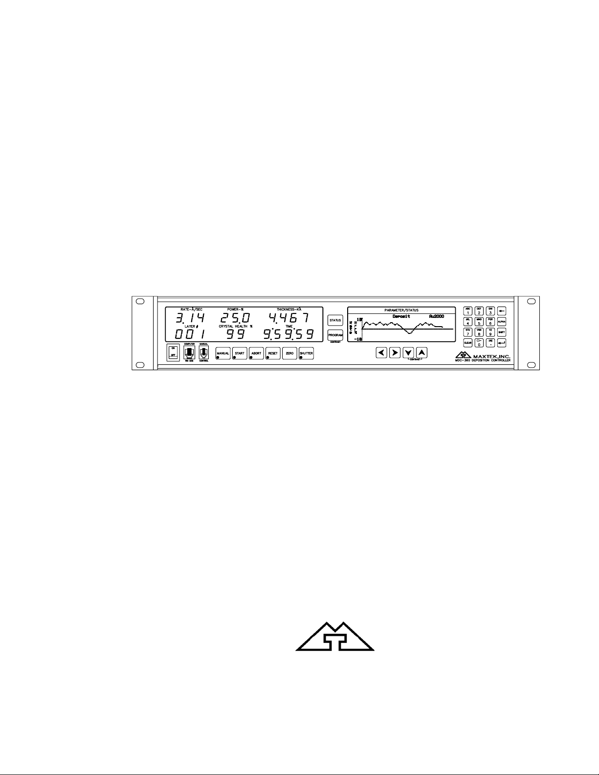
2. FRONT PANEL DISPLAYS AND CONTROLS
The front panel is divided into two sections, the operating section and the
programming section. The left half of the panel is devoted to the operating
displays and controls. The right half is used for programming, viewing stored
processes, and displaying the status of the selected process.
2.1 OPERATING DISPLAYS
All of the operating displays are updated ten times per second unless the
controller is in the Abort mode. When in the Abort mode, the values of the
operating displays are held constant so the operator will know the values at the
time of the Abort. The controller will also flash the operating displays while in
Abort to alert the operator.
Figure 2-1 Operating Display
2.1.1 RATE
A three digit display with a floatin
g decimal point is used to display deposition
rate in angstroms per second at a resolution of 0.1 Å/sec from 0 to 99.9 Å/sec, and
a resolution of 1.0 Å/se
2.1.2 POWER
A three digit display with a fixed decimal point displays percent of m
c for rates from 100 to 999 Å/sec.
aximum
power with a resolution of 0.1% from 0 to 99.9%. This corresponds to the control
voltage range of 0 to 9.99 v
2.1.3 THICKNESS
Four digits with an autoranging
olts.
decimal point display measured thickness in KÅ
with a resolution of 1 Å from 0 to 9.999 KÅ, a resolution of 10 Å from 10.00 KÅ
to 99.99 KÅ and a resolution of 100 Å from 100.0 KÅ
2.1.4 LAYER NUMB
ER
to 999.9 KÅ.
Three digits display the layer number of the current process.
2.1.5 CRYSTAL
HEALTH %
A two digit display is used to show the health percentage of the sensor crystal in
use. A fresh crystal starts out with a health of 99%.
FRONT PANEL DISPLAYS AND CONTROLS
2-1
Page 20
MDC-360 DEPOSITION CONTROLLER
p
2.1.6 TIME TO GO
Time To Go is displayed in hours, minutes and seconds. This display can be
configured to show the estimated state or layer time or the elapsed process, lay
er
or state times.
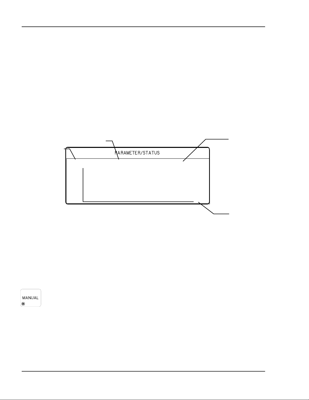
2.2 PARAMETER/STATUS DISPLAYS
A graphics display labeled Parameter/Status is used for process programming and
controller setup as w
operator can switch between programming screens and status screens by
ell as displaying run time status and data graphing. The
pressing
the Program and Status keys on the front panel. Upon power up, the
Parameter/Status display automatically reverts to the last viewed status screen.
Detail descriptions of the different programming and status screens can be found
in Section 4 and 5.
Displays the current
rocess name.
Figure 2-2 Parameter/Status Display
2.3 OPERATING CONTROLS
Normal operation of the MDC-360 is controlled by seven operating keys, Manu
Start, Abort, Reset, Zero, Shutter and Status. Except for the Zero and Status key
each of the other keys is equipped with an LED to indicate the controller’s statu
2.3.1 MANUAL KEY
This key is used to toggle the MDC-360 Manual mode on and off. A red light
behind this key indicates the controller is in manual power control mode. This
mode may be selected at any time providing that the controller is not in Abort
mode. The Manual mode indicates that the source control voltage output is bei
contro
voltage remains constant unless incremented up or down by means of the Rem
Power Handset. At entry into the Manual mode, the power is left at the
prior to entry and is thereafter modified only through the Remote Power Handset.
Exit from the manual mode is accomplished by means of the Manual or Reset
key.
Displays the current
material name.
Sample Cr Process Ready
10
R
a
t
e
0
1
Displays the
controller modes,
states or troubles.
Displays the ti
axis scale facto
lled through the Remote Power Handset. In the Manual mode the control
last value
me
r
al,
s,
s.
ng
ote
The MDC-360 can also be aborted through the Remote Power Handset. This
abort feature is active whether or not MDC-360 is in the manual mode.
FRONT PANEL DISPLAYS AND CONTROLS 2-2
Page 21
MDC-360 DEPOSITION CONTROLLER
2.3.2 START KEY
The Start key starts a process, starts a layer, or resumes an aborted process. A
green light behind this key indicates the controller is in process. When this key is
pressed the first time a list of stored processes is displayed in the Parameter/Status
window. The up and down arrow keys can be used to move the cursor to the
desired process. Press the Start key again to start that process. Note that in many
cases messages will be displayed in the Parameter/Status window reminding the
operator to check system set up. Follow the prompt.
2.3.3 ABORT KEY
The Abort key drives the MDC-360 into the Abort mode. All source powers are
set to zero and discrete outputs are set to inactive state. A red light behind this
key indicates the controller is in the abort mode.
2.3.4 RESET KEY
The Reset key is used to clear the controller from Abort mode and put it into the
Ready mode. A yellow light behind this key indicates a Ready mode. The Reset
key is inactive during the In Process mode so that a premature exit from the In
Process mode requires an abort.
2.3.5 ZERO KEY
Pressing the Zero key causes the thickness display to go to zero. This key is
active at all times and if pressed during the deposit state will result in a film
thicker than that desired by an amount equal to the thickness displayed at the time
the display was zeroed.
2.3.6 SHUTTER KEY
This key is used to manually open and close all source shutters. The red light is
illuminated when the active source shutter relay is closed. This key is only active
when the controller is in the Process Ready mode.
2.3.7 STATUS KEY
Pressing the Status key will bring up one of the six run-time status screens.
Repeatedly pressing the key will cycle through the different status screens. Refer
to Section 5 for a detailed description of these status screens.
FRONT PANEL DISPLAYS AND CONTROLS
2-3
Page 22
MDC-360 DEPOSITION CONTROLLER
Figure 2-3 Programming Section
2.3.8 ARROW KEYS
The arrow keys are used to navigate through the programming and setup menu
structure. These keys will auto-repeat if they are held down for more than half a
second.
Figure 2-4 Arrow Keys
2.3.9 PROGRAM KEY
Pressing the programming key will bring up the last viewed programming screen.
If a programming screen is already shown, nothing will happen. This key is also
used in conjunction with the Up and Down Arrow keys to adjust the contrast of
the Parameter/Status display.
FRONT PANEL DISPLAYS AND CONTROLS 2-4
Page 23
MDC-360 DEPOSITION CONTROLLER
2.3.10 ALPHANUMERIC KEYBOARD
Figure 2-5 Alphanumeric Keyboard
The alphanumeric keyboard is used to
edit controller programs. Refer to
Section 4 for the use of each key.
‘Backspace’
‘Enter’
FRONT PANEL DISPLAYS AND CONTROLS
2-5
Page 24

Page 25

MDC-360 DEPOSITION CONTROLLER
3. BENCH CHECKOUT & INSPECTION
3.1 INSPECTION
Your MDC-360 was released to the carrier in good condition and properly
packed. It is essential to all concerned that the contents of the shipment be
carefully examined when unpacked to assure that no damage occurred in transit.
Check the material received against the packing list to be certain that all elements
are accounted for. Items included with your controller are:
1 MDC-360 Deposition Controller
1 Operation and Service Manual
1 Power cord
1 Source cable (4 pin mini DIN connector)
1 Discrete I/O connector kit (37P D shell)
In addition, you may have ordered one or more of the accessories listed in Section
1.4. If there is evidence of loss or damage:
a) Notify the carrier or the carrier agent to request inspection of the loss
or damage claimed.
b) Keep the shipping containers until it is determined whether or not they
are needed to return the equipment to Maxtek.
3.2 INITIAL POWER UP
Upon initial power up the unit will start with all LED’s lighted. The
Parameter/Status display will show the controller Sign-on screen with its
configuration information. The unit will stay in this state until a key is pressed.
When any key on the front panel is pressed, the operating display and the
Parameter/Status display will return to the last viewed screen prior to loss of
power.
3.3 SAMPLE PROGRAM
The sample program listed below is included in the MDC-360 memory at the time
of shipment. It can be used to check out the controller by running it in Simulate
mode. Follow instructions in Section 4 to navigate through the menu structure.
Check the controller parameter values against the sample program for discrepancy
and change if necessary. Note also, if the source or sensor configuration has been
changed during familiarization with the controller programming, appropriate
source and sensor parameter values also need to be retained for the sample
program to run correctly.
Once the sample program has been checked, use the programming Main Menu,
Edit System Setup, Edit Utility Setup, to select Simulate mode ON, then use Start
to select and run the sample program in Simulate mode.
BENCH CHECKOUT & INSPECTION
3-1
Page 26

MDC-360 DEPOSITION CONTROLLER
3.3.1 MATERIAL #1 PARAMETERS
Material Name Cr
Sensor # 1
Crystal # 1
Source # 1
Pocket # 1
Material Density 07.20 gm/cm
3
Acoustic Impedance 28.95 gm/cm2 sec
Tooling Factor 70 %
Proportional gain 2400
Integral Time constant 99.9
Derivative Time constant 0.00
Rise to Soak Time 0:00:10 H:MM:SS
Soak Power 5 %
Soak Time 0:00:10
Rise to Predeposit Time 0:00:10
Predeposit Power 9.5 %
Predeposit Time 0:00:05
Rate Establish Time 0 sec
Rate Establish Error 0 %
Deposition Rate #1 10.0 Å/sec
Rate Ramp Start (1 to 4) 999.9 KÅ
Rate Ramp Stop (1 to 4) 999.9 KÅ
Time Setpoint 0
Ramp to Feed Time 0:00:05
Feed Power 7 %
Feed Time 0:00:10
Ramp to Idle Time 0
Idle Power 0
Maximum Power 20 %
Power Alarm Delay 5 sec
Minimum Power 0 %
Rate Deviation Attention 0 %
Rate Deviation Alarm 0 %
Rate Deviation Abort 0 %
Sample Dwell % 100.0 %
Sample Period 0
Crystal Fail Time Power
Backup Sensor # 1
Backup Tooling Factor 100
Backup Crystal # 1
Material Password 0000
3-2 BENCH CHECKOUT & INSPECTION
Page 27

MDC-360 DEPOSITION CONTROLLER
3.3.2 MATERIAL #2 PARAMETERS
Material Name Au
Sensor # 2
Crystal # 1
Source # 1
Pocket # 2
Material Density 19.30 gm/cm
3
Acoustic Impedance 23.18 gm/cm2 sec
Tooling Factor 70 %
Proportional gain 5000
Integral Time constant 99.9
Derivative Time constant 0.00
Rise to Soak Time 0:00:05 H:MM:SS
Soak Power 25 %
Soak Time 0:00:05
Rise to Predeposit Time 0:00:05
Predeposit Power 37.5 %
Predeposit Time 0:00:10
Rate Establish Time 0 sec
Rate Establish Error 0 %
Deposition Rate #1 20.0 Å/sec
Rate Ramp Start (1 to 4) 999.9 KÅ
Rate Ramp Stop (1 to 4) 999.9 KÅ
Time Setpoint 0
Ramp to Feed Time 0:00:05
Feed Power 10 %
Feed Time 0:00:10
Ramp to Idle Time 0
Idle Power 0
Maximum Power 50 %
Power Alarm Delay 5 sec
Minimum Power 0 %
Rate Deviation Attention 0 %
Rate Deviation Alert 0 %
Rate Deviation Alarm 0 %
Sample Dwell % 100.0 %
Sample Period 0
Crystal Fail Time Power
Backup Sensor # 1
Backup Tooling Factor 100
Backup Crystal # 1
Material Password 0000
BENCH CHECKOUT & INSPECTION
3-3
Page 28

MDC-360 DEPOSITION CONTROLLER
3.3.3 PROCESS PARAMETERS
Process Name Layer No. Thickness Material
Sample 1 0.400 KÅ Cr
2 1.050 KÅ Au
3.4 SIMULATE OPERATION
Testing the MDC-360 is best accomplished by checking its operation in the
Simulate mode. This mode can be selected by using the programming Main
Menu, Edit System Setup, Edit Utility Setup, to select Simulate mode ON, then
use Start to select and run a process in Simulate mode.
The Simulate mode is identical to the Normal mode except that the sensor input is
simulated. For this reason, entry to the Simulate mode will extinguish the Crystal
Failure message if it is flashing. No other difference between the Simulate mode
and the Normal mode occurs until entry to the Deposit State.
3.5 MANUAL OPERATION
Manual Mode is selected by depressing the Manual key. The LED behind the key
will light up indicating the controller is in Manual mode.
The Manual Mode is identical to the normal mode in all respects except that
source power is controlled only through the Remote Power Handset.
The Remote Power Handset has three push buttons, see Figure 3-1. Without any
of the buttons depressed, the output power is maintained at its last value.
Depressing the “PWR UP” button will increase the power, depressing the “PWR
DN” button will decrease the power and depressing the “ABORT” button will put
the controller into the Abort mode.
The Abort Mode is active whether or not the MDC-360 is in Manual Mode and
therefore can be used as a remote “panic button”.
The minimum increment by which the power is increased or decreased is 0.1%.
The Remote Power Handset can also be used to initiate a manual sensor and
crystal change by depressing both the power increase and decrease buttons
simultaneously. Each time a sensor/crystal switch is initiated, the controller will
toggle between the primary and the backup sensor/crystal combination as defined
by the active material’s parameters. The sensor/crystal switching function is only
operational when the controller is not in the Manual Mode.
3.6 INSTALLING OPTION BOARDS
Option boards are most easily installed while the MDC-360 is on the bench.
Figure 8-9 shows the location of the various option boards. Also, they are clearly
marked on the rear panel.
All Dual Source-Sensor boards are identical, as are all Discrete I/O boards. The
input-output configuration of these boards is defined by the position into which
3-4 BENCH CHECKOUT & INSPECTION
Page 29

MDC-360 DEPOSITION CONTROLLER
they are installed. One exception for the Discrete I/O boards is that the jumper J2
on the board installed in the Discrete I/O-2 position has to be connected. This is
required so the controller will acknowledge the second Discrete I/O board. A
Source-Sensor board plugged into the second position will provide sensor inputs
numbers 3 & 4, and source outputs numbers 3 & 4. The IEEE-488 board has a
single slot.
3.6.1 SOURCE-SENSOR BOARD
1. Remove the chassis top cover.
2. Remove the three plastic hole-plugs from the rear panel.
3. Carefully slide the two BNC connectors on the Source-Sensor board into
the two top holes on the rear panel. Then with even pressure, push the
card edge connector down into the Main board J12.
4. Fasten the two BNC connectors using the nuts and washers supplied with
the kit. Make sure the board is properly aligned.
5. Tighten the board down with the tie wrap.
6. Replace the chassis top cover and apply power to the controller.
7. The Sign On screen should acknowledge Source-Sensor 3,4 installed.
3.6.2 DISCRETE I/O BOARD
1. Remove the chassis top cover.
2. Locate Discrete I/O-2 slot and remove the slot cover.
3. Carefully slide the D37 connector of the DIO board into the slot and fasten
it using the hex fasteners and washers supplied with the kit.
4. Fasten the other end of the board to the standoffs using the two # 4-40
screws provided.
5. Plug the 26-pin ribbon connector into the DIO edge connector J1.
6. Replace the chassis top cover and apply power to the controller.
7. The Sign On screen should acknowledge Discrete I/O-2 installed.
3.6.3 IEEE-488 OPTION BOARD
1. Remove the chassis top cover.
2. Locate IEEE-488 option slot and remove the slot cover.
3. Carefully slide the connector of the IEEE-488 board into the slot and fasten
it using the fasteners and washers supplied with the kit.
4. Plug the 20-pin ribbon connector into J7 connector on the Main board.
5. Replace the chassis top cover and apply power to the controller.
6. The Sign On screen should acknowledge IEEE-488 option installed.
3.7 DIGITAL TO ANALOG CONVERTER (DAC) CHECKOUT
The built-in DAC function on the Main board contains two converters, allowing
simultaneous recording of any two of the following four parameters: Rate, Rate
deviation, Power and Thickness. The full scale output of each converter is 5
volts, is single ended and is referenced to ground. Parameter selection for each of
the channels is accomplished independently by making the appropriate choices in
the DAC setup menu.
BENCH CHECKOUT & INSPECTION
3-5
Page 30

MDC-360 DEPOSITION CONTROLLER
In addition to the individual channel output pins there are two control pins which
are common to both channels and are intended to simplify the process of setting
up analog recorders. Connecting the Zero control line to ground will drive both
channel outputs to zero, allowing the recorder zero reference to be easily set.
Releasing the Zero line and connecting the Full Scale line to ground will drive
both channel outputs to full scale for establishing the recorder full scale
calibration.
Each channel can be set independently to convert either the two or the three least
significant digits of the chosen parameter to a proportional analog signal,
corresponding to the DAC setup option chosen. With the three digit setting, a
thickness of 0.500 KÅ would result in an analog output of 2.50 volts, or a scale
factor of 5 mV/Å. If more resolution is desired, either channel can be configured
to convert only the last two digits of the parameter, thus the analog output would
achieve full scale at 99Å. The output scale factor in this configuration is 50
mV/Å.
The above scale factors are based on the assumption that the thickness display is
in the 0 - 9.999 KÅ range. Because the thickness and rate displays are autoranging, the analog output of these variables will also autorange so that in the
above example, if the thickness is in the range of 10 KÅ to 99.9 KÅ, the analog
scale factor would be 50 millivolts per 10 Å, also ten times larger.
The Rate deviation parameter must be handled differently than the other
parameters because it can be negative. Maximum positive error is converted to 5
volts, maximum negative error is converted to 0 volts and zero error is converted
to a mid scale, 2.5 volt, output. Maximum corresponds to 99 or 999, plus 1.
The DAC can be checked by putting the MDC-360 into the Simulate mode and
checking for correspondence between the analog output and the selected front
panel displays.
3-6 BENCH CHECKOUT & INSPECTION
Page 31

MDC-360 DEPOSITION CONTROLLER
Figure 3-1 Remote Power Handset
BENCH CHECKOUT & INSPECTION
3-7
Page 32

Page 33

MDC-360 DEPOSITION CONTROLLER
4. PROGRAMMING AND CONTROLLER SETUP
4.1 GENERAL
4.1.1 NAVIGATING THE MENU STRUCTURE
Before attempting to navigate the menu structure of the MDC-360 controller,
please refer to Section 2 which provides a brief summary of the front-panel
displays and key functions. A graphical menu structure is shown in Figure 15-1.
Note that following power-on, and acknowledgment of the Sign-on screen by
making any key depression, e.g. Reset, the LCD display will return to the display
function being used at the last power-off, i.e. either a status display screen or a
programming function screen.
This may be confusing until the full scope of the controller’s capabilities are
understood. However, as their names suggest, the Status and Program keys select
the display of status information and the display of programming information,
respectively.
So, for example, if having chosen the programming functions with a Program key
depression there is any doubt about the point in the menu system that is then
being displayed, holding down the left-arrow key will eventually display the Main
Menu from which point the desired option can be chosen by selective use of the
Up-arrow and Down-arrow keys to move the cursors to point to an option, and the
Right-arrow key or the Enter key to select the option.
Main Menu
>View/Edit Process <
View/Edit Material
View Results
Edit System Setup
Figure 4-1 The Main Menu
Press the Program key to enter the programming mode. The programming
screens can be visualized as a two dimensional menu format. The Main Menu
is
visualized at the far left, with an increasing level of detail in the menus to the
right. The Left and Right-arrow keys are used to move between menus. The Up
and Down-arrow keys are used to scroll through a list of parameters or option
each menu. To select a menu option, align the cursors with the option, then
s in
press
either the Enter key or the Right-arrow key. This will present the next screen
associated with the selected option. You can always hold down the Left-arrow
4-1PROGRAMMING AND CONTROLLER SETUP
Page 34

MDC-360 DEPOSITION CONTROLLER
key to go back to the Main Menu. Each of the programming screens is described
in detail later in this section.
4.1.2 ENTERING ALPHA CHARACTERS
To enter a name, press the k
ey that contains the letter or character you wish to
enter. Next, press the Alpha key to change the number to the first letter of that
key. K ep pressing the Alpha key
e to get the desired letter. Its upper/lower case
can be toggled by pressing the Shift key. Once the desired letter is achieved,
repeat the above procedure and enter the remainder of the name. Note, the
number 9 key contains characters Y, Z, and ‘space’. Use this key to ente
4.1.3 ENTERING TIME PARAMETERS
The MDC-360 expresses time in 24-hour h:mm:ss format. In p
rogramming a
r a space.
time parameter, the Decimal ‘.’ key is used to separate hour, minute and second.
Hence, 1:45:23 would be entered as “1.45.23” and 0:00:35 entered as “..35”,
followed by the Enter key.
4.1.4 COPYING AND DELETING
A ‘process’ is defined by one or more ‘layers’, and a layer requires
a ‘material’
and a thickness definition. The MDC-360 has the capability of copying and
deleting processes, layers, and materials. Except when copying a layer,
procedures for copying and deleting a process, a layer and a material are the same.
The difference when copying a layer is that layers are pushed-down to make
space for the new layer, and move
up when a layer is deleted.
To copy a process, position the cursor at the process to be copied, then press the
number 1 key. Next, move the cursor to the location where the process is to be
copied and press Enter. The
process will be copied to the new location with the
same name. If there is already a process name at the new location, it will be
overwritten. The copied process sho
confusion. The same procedure applies when copying a material.
When copying a layer, the copied data will be positioned at the selected layer
number. The data of the selected layer, and all following layers, will be p
down one layer. Example, if a layer is copied onto Layer #4 location, the exis
data in Layer #4 will be pushed to Layer #5, Layer #5 to Layer #6, etc., while the
copied data is placed in Layer #4.
To delete a process or a material, mo
A message will pop up asking for verification of the deletion, press 1 to confirm
and 0 to cancel the deletion.
4.1.5 PASSWORD PROTECTION
Each Process has a View/Run password and an Edit password. Each Material has
an Edit password. The three passwords protect against unauthorized operations.
The passwords default to 0000, or no password protection, at the time of
shipment. Refer to the descriptions below to set each password. Note: The
password protection is only meant to deter unsophisticated users. Be sure
4-2 PROGRAMMING AND CONTROLLER SETUP
uld be given a new name to avoid
ushed
ting
ve the cursor to the item and press the 0 key.
to
Page 35

MDC-360 DEPOSITION CONTROLLER
record passwords, because if you forget a password it will not be possible to
gain access to the protected item!
4.1.5.1 VIEW/RUN PROCESS PASSWORD
The View/Run password is required
password, select View/Edit Process from the Main Menu, select the process fro
to view or run a process. To set this
m
the Select Process screen. Move the cursor onto the View/Run password, type in
your password (4 digit string), then press the Enter key. A message will pop up
asking for verification to change the password. Press 1 to confirm and 0 to c
the change. Each time you want to view or run this process, you will now be
ancel
asked to enter the correct password. Note that the Edit Process password takes
precedence over the View/Run password. If you know the Edit password, you
can also view the process. Once
a password other than 0000 has been installed, it
will not be displayed unless re-entered.
4.1.5.2 EDIT PROCESS PASSWORD
The Edit process password is required to edit a process. To set this password
select View/Edit Process from the Main Menu, select the process from th
Process screen. Move the cursor onto the Edit password, type in your passwor
,
e Select
d
(4 digit string), then press the Enter key. A message will pop up asking for
verification to change the password. Press 1 to confirm and 0 to cancel the
change. Each time you want to edit this process, you will be asked to enter
correct password. Once a password other than 0000 has been installed, it will n
be displa
yed unless re-entered.
the
ot
4.1.5.3 EDIT MATERIAL PASSWORD
The Edit material password is required to edit a material. To set this password,
select View/Edit Material from the Main Menu, select the material from the
Select Material screen. Move the cursor down to the Material Password
parameter, the last item in the list, type in your password (4 digit string), then
press the Enter key. A message will pop up asking for verificat
ion to change the
password. Press 1 to confirm and 0 to cancel the change. Each time you want to
edit this material, you will be asked
password other than 0000 has been installed, it will not be displayed unless
to enter the correct password. Once a
re-
entered.
4.1.6 ADJUSTING PARA
The Parameter/Status display contrast can be adjusted by using the Progr
METER/STATUS DISPLAY CONTRAST
am key
in conjunction with the Up-arrow and Down-arrow keys. Hold down the Program
key and press the Up-arrow key to increase the contrast. Likewise, hold down the
Program key and press the Down-arrow key to
decrease the contrast. It may take
several seconds for the change in contrast to become apparent.
4-3PROGRAMMING AND CONTROLLER SETUP
Page 36

MDC-360 DEPOSITION CONTROLLER
4.2 GETTING STARTED
This section lays out the basic programming sequence with programming
examples for initial setup of the MDC-360 deposition controller.
4.2.1 UTILITY SETUP
The only critical parameter in the Utility Setup is the Crystal Frequency
parameter. This parameter must be set for the specific frequency crystals th
at you
plan to use (2.5, 3.0, 5.0, 6.0, 9.0, 10.0 MHz).
There is one other parameter in the Utility Setup menu that may be useful in the
initial setup and testing phase of the MDC-360 and that is the Simulate Mode
parameter. The simulate mode of the MDC-360 provides a means of simulatin
deposition
on the crystal. This mode is useful for testing the setup of the MDC-
g
360 without having to deposit any material.
4.2.2 DAC SETUP
If the DAC (digital to analog) outputs are to be used then these parameters can be
set at this time but it is not necessary for the operation of the controller.
4.2.3 SOURCE SETUP
The first item to note is that in defining s
the
MDC-360 will automatically create the inputs and outputs necessary to
comple e setup
is comp
assignm that the I/O
pin t
scr
The us
There a
outputs
program ard card has TTL ground true inputs
wh
des
The of
sou
te the interface based on the parameter settings. Therefore, once th
lete, the user should review the inputs and outputs noting the pin
ents so that the proper connections can be made. Also note
assignments can be changed if necessary in the program input and outpu
eens.
er must also be aware of the type of I/O card installed in the MDC-360.
re two types of I/O cards available. Both cards have the same 9 relay
(8 programmable and 1 abort) and the same number of inputs (8
mable). The difference is the stand
ile the Active I/O card has 115VAC high true inputs. The Active I/O card is
ignated by “Active I/O Card“ written on the rear panel of the MDC-360.
following two items in the Source Setup are common to almost all types
rces and typically require definition:
Source Shutter - If the source has a shutter to be activated by the MDC-36
ources, and sensors for that matter, is that
0
then the Shutter Relay Type parameter must be set to either N.O.
(normally open) or N.C. (normally closed). The typical setting is N.
which means th
at the relay will close to open the shutter.
O.
Once defined, the MDC-360 will create a relay output called “SourceN
Shutter” that should be connected to the shutter actuator. The shu
be tested by pressing the Shutter key with the c
Ready state. When the red LED in the Shutter key is illuminated then all
source shutters should be opened. When the shutter LED is off then all
source shutters should be closed.
4-4 PROGRAMMING AND CONTROLLER SETUP
tter can
ontroller in the Process
Page 37

MDC-360 DEPOSITION CONTROLLER
If th
e shutter actuator has a significant delay in opening and closing then set
the Shutter Delay parameter equal to the delay
.
Source Voltage - This parameter must be set to correspond to the input
voltage range of the source power supply (0 to 2.5, 5.0 or 10.0 volts).
The set
source
manual
Sin
Mu
Mu
tings of the rest of the source parameters are dependent on whether the
has one or more pockets (crucibles) and whether pocket selection is
or automatic.
gle Pocket Source - If the source has only one pocket (single pocket E-
beam gun, filament boat or sputtering source) then the remaining
parameters can be left at their default values.
ltiple Pocket Source with Manual Position Control - For manual
position control of a
multiple pocket source, you need only set the Number
of Pockets parameter to the correct number of pockets. Once set, a
message will appear at the start of each layer instructing the operator to
change source N to the required material.
ltiple Pocket Source with Automatic Position Control - There are two
parameters requiring definition which are common to all the various types
osition control. The first is the Number of Pockets parameter and the
of p
ond is the Rotator Delay parameter. The Number of Pockets parameter
sec
imply the number of pockets in the source. The Rotator Delay
is s
ameter defines the maximum amount of t
par ime allowed for the correct
pocket to rotate into position. This should be set to the time it takes for
the rot
The se
pocke osition control and
ator to go from pocket #1 all the way around to pocket #1 again.
ttings of the three remaining parameters required for automatic
t position control depend on the required type of p
position feedback.
Positi t
on Control - The MDC-360 can be setup to either control the pocke
positio
interfa
Direct eans that the MDC-
a. Un rive - The rotator drive motor can only turn in
n directly by interfacing to the rotator’s actuator or indirectly by
cing to a rotator controller.
Control of Pocket Position - Direct control m
360 will control the actuator (rotator motor, pneumatic valve, e
directly to get the desired pocket into position. For direct contr
se
t the Control Parameter to Direct then select one of the following
dr
ive types and follow the instructions:
idirectional Motor D
tc.)
ol first
one direction. Select Up for the Drive parameter. A relay output
will be created called “SourceN Drive Up” that should be connected
between the rotator motor and power supply.
b. Bi-
directional Motor Drive - The rotator motor can turn in either
direction. Select Fast for the Drive parameter. Two relay outputs
will be created. One called “SourceN Drive Up” and one called
“SourceN Drive Dn”. With this drive
type, the MDC-360 will
4-5PROGRAMMING AND CONTROLLER SETUP
Page 38

MDC-360 DEPOSITION CONTROLLER
activate either the drive up or drive down outputs to rotate to the
required pocket in the least amount of time.
c. Motor Driven Inline Source - Select Inline for the Drive type
parameter. Two relay outputs will be created. O
“
SourceN Drive Up” and one called “SourceN Drive Dn”. In this
c t
ase the up output will be activated when going from the greates
p
ocket to pocket #1.
ne called
d. Uni c Drive - Select Sngl Step or Dbl Step for the
directional Pneumati
D
rive parameter. A relay output will be created called “SourceN
D
rive Up” that should be connected between the rotator’s
p l
neumatic valve and power supply. With Sngl Step, the output wil
p .
ulse once for one second to increment the rotator one position
W
ith Dbl Step, the output will pulse twice for one second each to
i otator one position.
ncrement the r
Indirect Control of Pocket Position - Indirect control means that the MDC-
360 will indicate the desired pocket position to a pocket rotator contro
through position select outputs. The Drive pa
rameter selects between the
ller
two following indirect position output formats:
a. Individual - With individual format, one output will be created
for each pocket. So, if pocket 2 is the desired pocket, then the
output “SourceN Pocket 2” will be true while all the other positio
outputs will be false.
b. BCD - With BCD format , the MDC-360 will create from one
to three outputs based on the number of pockets. For example, an
eight pocket source would use three outputs. If pocket one is t
d pocket, all outputs will be false. If pocket four is the
desire
desired pocket, outputs one and two will be true and outpu
he
t three
will be false.
n
Pos eed t
ition F back - The last step in defining automatic control of a multi-pocke
sou
rce is to select the pocket position feedback type. The MDC-360 has the
followi
ng five types of position feedback available:
No
Feedback - As the name implies, no position feedback is created for this
type.
Ind his feedback type, one input is created for each pocket
ividual - For t
position in the source. The inputs are labeled “SourceN Pocket X”. All
inputs are normally false (open circuit) unless the respective pocket
position then that input should be true (closed to gr
six pocket source would use six inputs. If pocket two was in position the
all the inputs should be false except the input connected to “SourceN
Pocket 2”.
Individual position feedback is the most typical feedback type and is
recommended if more than one type is available.
4-6 PROGRAMMING AND CONTROLLER SETUP
is in
ound). For example, a
n
Page 39

MDC-360 DEPOSITION CONTROLLER
BCD - Binary Coded Decimal position feedback. This feedback type
uses binary coding to indicate the pocket position. Inputs are numbered
most significant bit first. For example, an eig
ht pocket source would use
three inputs. With pocket one in position, all inputs will be false. With
pocket four in position, inputs one and two will be true and input three
will be false.
SNGL HOME - Single home position feedback. This feedback type uses one
input. The input is normally false (open circuit) and should go true
(closed to ground) when pocket one is in position.
POSITION - In position feedback. This feedback type uses one input.
IN
The input is normally false (open circuit) and
should go true (closed to
ground) when the desired pocket is in position.
4.2.4
The fol -360 is setup to control the
fou
SENSOR SETUP
lowing examples demonstrate how the MDC
r basic types of crystal sensor heads available:
Sin for a
gle Crystal Sensor Head - No sensor parameters need to be changed
single crystal sensor head.
gle Crystal Sensor Head with Shutter - For a single shuttered sensor
Sin
head, set the Shutter Relay Type parameter to either N.O. (normally open
or N.C. (normally closed). The typical setting is normally open which
means that
“SensorN Shutter” will be created that should be connected between
the relay will close to open the shutter. A relay output called
the
sensor shutter actuator and power supply.
Du ensor
al Crystal Sensor Head with Shutter - For a dual crystal shuttered s
hea
d, set the Shutter Relay Type parameter to Dual. A relay output called
“Du
alSnsr1&2 Shtr” will be created that should be connected between the
sen
sor shutter actuator and power supply.
Autom in the material menu by
atic crystal switching upon failure is enabled
sett
ing the Crystal Fail parameter to Switch and the Backup Sensor
num r
ber to 2. Note that with the dual sensor head you define the senso
num
ber that you would like to use, (or switch too) not the crystal number.
The ple
crystal number need only be defined when you are using a multi
cry
stal sensor head(sensor head with one BNC output and more than one
cry
stal).
)
Multip
le Crystal Sensor Head - The MDC-360 can be setup for either
auto
matic or manual control of multiple crystal sensor heads.
a. Manual Crystal Pos
control of a multiple crystal sensor head, set the Number of Crystals
parameter to the correct number of crystals. Once set, a message w
appear at the start o
sensor N to the required crystal number.
ition Control - For manual crystal position
ill
f each layer instructing the operator to change
4-7PROGRAMMING AND CONTROLLER SETUP
Page 40

MDC-360 DEPOSITION CONTROLLER
b. Automatic Crystal Position Control - There are two parameters
requiring definition which are common to all the various types of
multiple sensor heads. The first is the Number of
and
the second is the Rotator Delay parameter. The Number of
Cry
stals parameter defines the number of crystals in the sensor head.
The Ro
allowed
set to th
around
The
crystal po
position fe
Pos l the
cry
indirectly
tator Delay parameter defines the maximum amount of time
for the correct crystal to rotate into position. This should be
e time it takes for the rotator to go from crystal #1 all the way
to crystal #1 again.
settings of the three remaining parameters required for automatic
sition control depend on the type of position control and
edback.
ition Control - The MDC-360 can be setup to either contro
stal position directly by interfacing to the rotator’s actuator or
by interfacing to a rotator controller.
Crystals parameter
Direct
Control of Pocket Position - Direct control means that the
M
DC-360 will control the actuator (rotator motor, pneumatic
va ired crystal into position. For
lve, etc.) directly to get the des
direct control, set the Control Parameter to Direct then selec
t
one of the following drive types and follow the instructions:
a. Un
idirectional Motor Drive - Select Up for the Drive
parameter. A relay output will be created called “SensorN
Drive Up” that should be connected between the rotator
motor and power supply.
b. Bi-
directional Motor Drive - Select Fast for the Drive
parameter. Two relay o
utputs will be created. One called
“SensorN Drive Up” and one called “SensorN Drive Dn”.
With this drive type, the MDC-360 will activate either the
drive up or drive down outputs to get to the required crystal
in the least amount of time.
d. Unidirectional Pneumatic Drive - Select Sngl Step or Dbl
Step for the Drive parameter. A relay output will be crea
ted
called “SensorN Drive Up” that should be connected
between the rot
ator’s pneumatic valve and power supply.
With Sngl Step, the output will pulse once for one second to
increment the rotator one position. With Dbl Step, the
output will pulse twice for one second each to increment the
rotator one position.
Indirect C
360 wi esired crystal position to a crystal rotator controller
ontrol of Crystal Position - Indirect control means that the MDC-
ll indicate the d
through position select outputs. . The Drive parameter selects between the
two following indirect position output formats:
a. Individual - With individual format, one output will be created
for each crystal. So, if crystal 2 is the desired cry
4-8 PROGRAMMING AND CONTROLLER SETUP
stal, then the
Page 41

MDC-360 DEPOSITION CONTROLLER
output “Senso N tal2r Crys ” will be true while all the other position
outputs will b fa
e lse.
4.2.4.1
b. BCD - With BCD format , the MD
to three outputs based on the number
eight crystal sensor head will use three o
the desire sta output
desired crys n
will be fa
EXAMPLE USING MAXTEK’S RSH-600 SIX CRYSTAL SENSOR HEAD
d cry l, all s will be false. If crystal four is the
tal, outputs o two will be true and output three
e and
lse.
C-360 will create from one
of crystals. For example, an
utputs. If crystal one is
The following is a list of the sensor parameter settings required to control
Maxtek’s RSH-600 six crystal sensor head.
Number of Crystals - 6
Shutter Relay Type - None
Control - Direct
Drive - Sngl Step
Feedback Type - Indiv
Rotator Delay - 30
With the above parameter settings, the
MDC-360 will create six position
feedback inputs called “SensorN CrystalX” where X ranges from 1 to 6.
These inputs should be connected to the six position feedback pins o
RSH-600 sensor head. Pin #1 of connector J1 on the sensor head sho
n the
uld
be connected to the “SensorN Crystal1” input on the MDC-360. Pin #2
the sensor head should be connected to “SensorN Crystal2” on the M
360 and so on. Pin #7 on the sensor head should be connected to pin
or any of the return pins w
hen using the standard 360 I/O board. When
using the 360 Active I/O board then pin #7 of the sensor head should b
DC-
#12
e
connected to one side of a 115VAC source. The other side of the
115VAC source should be connected to the other side of the six position
feedback inputs on the 360.
on
4.2.5
The or
an inte
control
require
The fol
program
INPUT, OUTPUT AND ACTION SETUP
MDC-360’s inputs, outputs and actions can be used to provide control for,
rface to all sorts of vacuum system peripherals such as PLC system
lers, substrate heaters, planetary rotators, etc. If your system doesn’t
any special interfacing or control then you can skip to the next section.
lowing are a few examples of some typical uses for the MDC-360’s
mable I/O’s and actions.
Optical Monitor Termination - To setup the MDC-360 to terminate the
deposit on a signal from an optical monitor, the first step is to prog
input that will be connected to an output in the op
tical monitor. Go to the
ram an
Program Inputs screen and select a blank input. Name the input “Optical
4-9PROGRAMMING AND CONTROLLER SETUP
Page 42

MDC-360 DEPOSITION CONTROLLER
Monitor” for future identification. Note the I/O card and the pin numbers
of the input so you can later connect the input to the optical monitor.
xt, go to the Program Actions screen and select any action labeled “No
Ne
Action”. Press the right arrow key with the cursor on the action Nam
parameter and select the TerminateDeposit action. Move the curs
Conditions fi
eld and press the 0 key to add a condition. Move the cursor
e
or to the
down to the Input condition type, press the right arrow key, move the
cursor onto the “Optical Monitor” input and press enter. Press enter agai
to complete the condition string.
w, the MDC-360 will terminate the deposit whenever the “Optical
No
Monitor” input is set true by the optical monitor.
Sub
strate Heat Control - To create an output in the MDC-360 to switch on
and off a substrate heat controller, first go to the Program Outputs screen
and select a blank output. Name the output “Substrate Heat” for future
identification. Note
the I/O card number and the pin numbers of the
output so you can later connect the output to the substrate heater
controller.
Next, move the cursor onto the Conditions field and press the 0 key to add
a condition. With th
arrow key and select the state in which you would like the heater to
e cursor on the State condition type, press the right
first
turn on. If you would like the heater on during more than the one state,
then press the 5 key to add an or “|” symbol then press 0 to add the next
desired state. Repeat this process until all of the states requiring substrate
heat have been added to the condition. For example, if you would like
substrate heat to start in the Predeposit Hold state and continue through t
Deposit
1 state then your condition string would look like this “Predeposit
Hold|Deposit 1”.
n
he
With the condition string completed, the MDC-360 will set this output tr
when ever it is in the selected states.
4.2.6 DISPLAY SETUP
The only parameter in the Display Setup menu that affects the controller’s
function is the Pause On Layer Complete parameter. This parameter determines
whether or not the controller will pause at the completion of each layer. When
to Yes, the contro
ller will stop at the end of each layer and wait for a Start key
press before continuing. When set to No, the controller will immediately go
the next layer.
4.2.7 MATERIAL SETUP
The
next step in the initial setup of the controller is to define the materials that
you of
wish to deposit. Because of its many features, the MDC-360 has a long list
mat t
erial parameters which at first can be overwhelming. Fortunately, the defaul
sett efine is disabled when
ings of most parameters are such that the feature they d
left at the default. This section will list the material parameters typically set for
4-10 PROGRAMMING AND CONTROLLER SETUP
ue
set
to
Page 43

MDC-360 DEPOSITION CONTROLLER
all materials and the parameters which must be set to utilize the different feature
he MDC-360. For a detailed description of any mate
of t rial parameter, go to
s
Section 4.3.2.1.
following is a list of the material parameters that
The are typically set when
defining a new material:
cess Name - If you select a material from the default material library (pres
Pro s the
right arrow key from the material name parameter and press enter on the
desired material) then the density and acoustic impedance for that material
will be entered automatically. If your material is not in the library then yo
u
must enter the name, density and acoustic impedance.
Sensor input and crystal number - Defines the sensor and crystal number o
f the
sensor which will be used to monitor this material.
Source output and pocket number - Defines the source and pocket number of the
source that the material will be deposited from.
Tooling Factor - Used to correlate the controller’s rate and thickn
ess readings
with those on the substrates. This parameters is determined empirically.
Control loop parameters (Proportional Gain, Integral Time, Derivative Time).
The default settings for these parameters are a good starting point.
Deposit Rate #1 - Defines the target deposit rate for the material.
Maximum Power - Defines the maximum deposit power for the material.
The above parameters are typically all that are needed to deposit the most basic
materials. I
neglected. The following is a list of the more specialized features defin
f no other features are required then the remaining parameters can be
ed by the
material parameters. All of the features are disabled by default.
4.2.7.1 POWER RAMPS
Pow sed for source material conditioning prior to and after the
er ramps are u
deposit states. A power ramp is defined by a ramp time, a ramp too po
and a hold time before the next state. There are two power ramps avai
wer level
lable prior
to and one after the deposit states. The first ramp prior to deposit is the soak and
the second is the predeposit. If only one ram
p is needed prior to deposit then you
should use the predeposit ramp. The power ramp after the deposit states is called
the Feed.
The parameters used to define the three power ramps are as follows:
Soak Power Ramp - Rise to
Predeposit Power Ramp - Rise to Predeposit Time, Predeposit Power and Ram
Soak Time, Soak Power and Soak Time
p
to Feed Time
Feed Power Ramp - Ramp to Feed Time, Feed Power and Feed Time
4-11PROGRAMMING AND CONTROLLER SETUP
Page 44

MDC-360 DEPOSITION CONTROLLER
4.2.7.2 AUTOMATIC CRYSTAL SWITC HING
To enable automatic Crystal switching upon failure, set the Crystal Fail paramete
to Switch then set the Backup Sensor, Backup Tooling and Backup Crystal
parameters to define the backup sensor and crystal.
4.2.7.3 RATE ESTABLISH
The rate establish feature is used in critical processes where it is important to
establish the correct de
position rate prior to opening the source shutter and
depositing on the substrates. To use this feature, the sensor head must be
mounted in such a way that it is in the material vapor stream with the source
shutter either opened or closed.
To enable this feature you must set the Rate Estab. Time and Rate Estab. Error
parameters. Th
e Rate Establish Time parameter sets the maximum time that the
controller will attempt to keep the rate error within the Rate Estab. Error limit for
a period of five seconds. If the rate error condition is
time then the controller will enter the deposit state. If not, then the process w
meet within the allotted
ill be
halted and a Rate Establish Error will be displayed.
r
4.2.7.4 RATE RAMPS
Rate ramping is typically used at the beginning of the deposition to ease the rate
up slowly to prevent material spitting. Rate ramping is also used towards the end
of the deposition to achieve a more accurate endpoint thickness. By slowing
down the rate, the thickness overshoot caused by the delay of the shutter
closing
is diminished
The MDC-360 has four rate ramps available. A rate ramp is defined by its R
amp
Start and Ramp Stop Thicknesses and the final rate.
The rate
ramps are disabled by default with the Ramp Start and Ramp Stop
Thicknesses set to 999.9.
4.2.7.5 RATE SAMPLE MODE
Rate sample feature is designed for large deposition thicknesses where c
rystal life
is a problem. . By sampling the rate periodically to maintain rate control, then
closing the sensor shutter with the rate and power level constant, a large
deposition thickness can be achieved with one crystal.
To enable the rate sample feature, set the Sample Dwell% parameter to the
percentage of time you wish
the controller to sample the rate. Then set the
Sample Period parameter to the time period of the sample and not sampling
period.
4.2.
7.6 RATE DEVIATION ALARM
The MDC-360 provides three rate deviation levels to
an alarm sound, or a process abort. The attention an
momentarily triggered meaning they will sound when the error is exceede
4-12 PROGRAMMING AND CONTROLLER SETUP
trigger an attention sound,
d alarm sounds are
d and
Page 45

MDC-360 DEPOSITION CONTROLLER
clear when within the limit. The process will abort when the abort level is
eeded and the power is at the maximum or minimum power. exc
4.2.8 PROCESS SETUP
The final step in the initial setup of the controller is to define the processes that
i you should complete the following steps:
you w sh to run. To define a process
Select a blank process from the Select Process Screen. Please note that you can
also copy and modify a similar process to save time.
Enter a process name in the Define Process Screen.
Move the cursor onto the layer thickness parameter and e
nter the desired
thickness for the layer.
Select a material for the layer by moving the cursor onto the material column,
pressing the right arrow key, moving the cursor onto the desired material for
the layer and pressing the Enter key.
Repeat steps c&d until the process layers are co
4.2.9 STARTING A NEW PROCESS
To start a new process, the controller m
ust be in the Process Ready state. If not,
mplete.
press abort then reset. From the ready state, press the start key, move the cursor
onto the desired process and press start again to start the process.
4.2.10 RESUMING A PROCESS FROM ABORT OR HALT
To resume an aborted process, first press the start key. A message will appea
r
asking you to press the start key again to resume the process. The process will
resume from the layer where the process was aborted starting in either the Rise to
Soak or Rise to Predeposit power states. Once in deposit, the thickness will
continue from the last value prior to the abort.
4.3 DETAILED PROGRAMMING
4.3.1 VIEW/EDIT PROCESS
Selecting View/Edit Process from the Main Menu will present the Select Process
screen to delete, copy, view or edit any one of up to 99 processes.
To select a process for viewing and editing, move the cursor onto the desired
process using the Up-arrow and D
own-arrow keys, then press the Enter key.
PROGRAMMING AND CONTROLLER SETUP
4-13
Page 46

MDC-360 DEPOSITION CONTROLLER
y
02 Au
03
04
05
1 - Copy process 06
0 - Delete process 07
-
Figure 4-2 Select Process screen
4.3.1.1 DEFINE A PROCESS
Process Name Layer# Thickness Material
>Sample < 001 0.500 Cr
Edit 0000 002 1.350
View/Run 0000 003 0.000
004 0.000 End Layer
005 0.000 End Layer
006 0.000 End Layer
007 0.000 End La
Au
End Layer
< Select Process: 01 >Cr
er
Figure 4-3 Define Process screen
Selecting a process will bring up the Define Process screen as shown in Figure
4-3. In this screen you enter all of the parameters that define a process. A
process consists of a twelve-character name, two levels of passwords and finally a
sequence of layers that makeup the process. Each layer consists of a material and
the desired thickness for the layer. A process can have from 1 to 999 layers as
long as the total number of layers in all the processes is not greater than 999. The
following list describes all of the p rocess parameters:
Process Name (twelve character alphanum
eric field)
Each process is referenced by a twelve-character alphanumeric process name.
You enter a process name using the alphanumeric keypad as described in
ENTERING ALPH
process name is displayed in the upper left
A CHARACTERS section 4.1.2. Please note that the active
-hand corner of all the status screens.
Edit Password (four character alphanumeric field)
The Edit process password allows you to lock out other users
process unless the correct pa
cursor onto the Edit passwor
ssword is known. To set this password, move the
d field, type in your password then press the Enter
from editing a
key. A message will pop up asking for verification to change the password. Press
4-14 PROGRAMMING AND CONTROLLER SETUP
Page 47

MDC-360 DEPOSITION CONTROLLER
1 to confirm and 0 to cancel the change. Each time you want to edit this proces
you will be asked to enter
entered, th
is parameter will not be displayed until the password has been entered
the correct password. Once a password has been
s,
again.
The default for this parameter is '0000'.
Please note that once the password has been changed, the process cannot be
modified unless the correct password is entered so
you must remember your
passwords.
View/Run Password (four character alphanumeric field)
The View/Run process password allows you to lock out other
users from viewing
and/or running a process unless the correct password is known. To set this
password
, move the cursor onto the Edit password field, type in your password
then press the Enter key. A message will pop up asking for verification to change
the password. Press 1 to confirm and 0 to cancel the change. Each time you want
to view or run this process, you will be asked to enter this password. Please note
that the view function of this password is ignored if the Edit Password is not set.
Once a password has been entered, this parameter will not be displayed until the
password has been entered again.
The default for this parameter is '0000'.
Please note that once the password has been changed, the process cannot be
viewed or run unless the correct password is entered so you must remember
your passwords.
Layer (000 to 999)
This column shows the layer number in the process. Please note that with the
cursors on a layer number you ca
n copy or delete this layer.
Thickness (000.0 to 999.9)
This parameter defines the desired thickness for the layer. The default for this
parameter is 0.000 Kang.
Material
This p
from the list of m aterial. Therefore, you should
define
See E n 4.3.2.
To se e materi
arameter defines the material for this layer. The layer material is s elected
aterials defined in View/Edit m
all of the necessary materials for the process before defining the process.
DIT MATERIAL PASSWORD sectio
lect a material, move the cursors to th al parameter for that layer and
press the Right-arrow key. The Select Layer Material screen will be displayed as
shown below. Scroll to the desired material and press Enter.
The layer material defaults to 'End Layer' meaning this layer marks the end of the
process.
4-15PROGRAMMING AND CONTROLLER SETUP
Page 48
MDC-360 DEPOSITION CONTROLLER
Select Layer Material: 01 >Cr <
02 Au
03
04
05
06
07
Figure 4-4 Select Layer Material screen
4.3.2 VIEW/EDIT MATERIAL
From the Main Menu, selecting View/Edit Material w
Material screen shown below.
ill present the Select
Select Material: 01 >Cr <
02 Au
03
04
1 - Copy m
0 - Delete material 07
-
05
aterial 06
elect Material screen Figure 4-5 S
4.3.2.1 DEFINE A MATERIAL
Selecting a material for viewing and/or editing will present the screen which
permits the material to be defined, shows the first page of this screen. In this
screen, you define al
material parameters are described in detail below
l of the material parameters for the selected material. The
.
4-16 PROGRAMMING AND CONTROLLER SETUP
Page 49

MDC-360 DEPOSITION CONTROLLER
Material Name: >Cr <
Sensor 1
Crystal 1
Source 1
Pocket 1
Density 07.20 gm/cm^3
Acoustic Impedance 28.95 gm/cm^2/sec
Figure 4-6 Define Material screen
1. Material Name (A ten character material name)
The material name parameter allows you to either use the keypad to type in a
name, or pick a name from the materials already stored in the material library.
To pick
parameter and press the Ri
materials that are stored in the MDC-360.
on ess Enter key. Once a material is chosen, the stored
values for the density and acoustic impedance f
entered into their respective param
a material from the material library, move the cursor to the material
ght-arrow key. This will display a complete list of
To pick a material, move the cursor
to that material and pr
or that material are automatically
eters.
2. Sensor# (1 to 4)
This parameter defines the sensor input number that will be used for this material,
and cannot be greater than the number of sensor inputs fitted to the controller. Th
default setting is 1.
3. Crystal# (1 to 8)
This parameter defines the primar
parameter cannot be greater than the N
y crystal used to monitor this material. This
umber of Crystals parameter in the Sensor
Setup screen. . The default setting is 1.
4. Source# (1 to 4)
This parameter defines the source output number that will be used for this
material, and cannot be greater than the number of source outputs fitted to the
controller. The default setting is 1.
e
5. Pocket# (1 to 8)
This parameter defines the pocket number that contains this material. This
parameter cannot be greater than the Number Of Pockets parameter in the Source
Setup screen. The default setting is 1.
6. Density (0.80 to 99.99 gm/cm
This par
ameter provides the material density so that the controller can calculate
and display the physical film thickness
3
)
. If the film density is known it should be
PROGRAMMING AND CONTROLLER SETUP
4-17
Page 50

MDC-360 DEPOSITION CONTROLLER
ρ
used. A list of the more commonly used film densities is presented in Table 10-1.
As a first approximation, bulk material density can be used in programming.
Empirical calibration of this parameter is described in Section 10.6.1.
7. Acoustic Impedance (0.50 to 59
This parameter is the acoustic impedance of the material. The acoustic
impedance of the deposited film is required b
accurately establish the sensor scale factor wh
loaded. If the acoustic impedance of the film mater
directly in units of 10
bulk material can be used and can be obt
other source of acoustic data. The shear
shear wave acoustic impedance can be c
shear wave velocity and the density by using the following equation:
5
gm/cm2 sec. In most cas
.99 gm/cm
ained from The Handbook of Physics or
wave impedance should be used. The
alculated from the shear modulus or the
2
/sec)
y the MDC-360 in order to
en the sensor crystal is heavily
ial is known, it can be entered
es the acoustic impedance of the
AI C G=⋅= ⋅
Where:
AI= Acoustic Impedance
= Density (gm/cm3)
C= Transverse (shear) wave velocity (cm/sec)
G= Shear Modulus (dynes/cm2).
A list of the acoustic impedance and density of the more commonly dep
materials is presented in Table 10-1 and
this parameter is presented in Section 10.6.3.
In many cases and particularly if the s
sufficient accuracy can be achieved by
which is 8.83 X 10
8. Tooling Factor (10.0 to 499.9%)
This parameter is the tooling factor for the primary sensor. The Tooling Factor
parameter is used to compensate for geometric factors in th
which result in a difference between the
rate on the sensing crystal. This param
corresponds to equal rates at the substrate and at the sensing crystal. To a first
approximation the tooling factor can be calculated using the following equatio
5
gm/cm2 sec.
ρρ
a technique for empirically determining
ensor crystal is not heavily loaded,
using the acoustic impedance of quartz
deposition rate on the substrates and the
eter is entered in percent units and 100%
osited
e deposition system
n:
2
⎛ ⎞
dc
⎟
ds
⋅
100
where:
dc= Distance from source to crystal.
4-18
PROGRAMMING AND CONTROLLER SETUP
Tooling
% =
⎝⎜⎠
Page 51

MDC-360 DEPOSITION CONTROLLER
ds= Distance from source to substrate.
Empirical calibration of the tooling factor is described in Section 10.6.2.
9. Proportional Gain (0 to 9999)
This parameter is the proportional gain factor for the source power control loop.
10. Integral Time constant (0 to 99.9 sec)
This parameter is the system time constant.
11. Derivative Time constant (0 to 99.9 sec)
This parameter is the system dead time.
12. Rise To Soak Time (0 to 9:59:59)
This parameter sets the time interval for the source power to ramp up from zero t
the power level set in Soak Power parameter. It should be long enough for the
material to have time to reach equilibriu
case of evaporation sources, protected from
m temperature without spitting, or in the
unnecessary thermal shock.
13. Soak Power (0.0-99.9%)
This parameter defines the source power le
vel during the Soak state. The Soak
Power should be established at a level which will assure that the source material i
properly outgassed and prepared for subsequent deposition.
14. Soak Time (0 to 9:59:59)
The Soak Tim
conjunction with the Soak Power to allow t
e parameter defines the time duration of the Soak state. It is used in
he material to fully outgas.
15. Rise To Predeposit (0 to 9:59:59)
This parameter sets the time interval for the
source power to ramp from Soak
Power level to the Predeposit Power.
16. Predeposit Power (0.0 to 99.9%)
This parameter defines the source power level during the Predeposit state. This
should be set as close as possible to the power level required to reach the desire
deposition rate. The Manual mode can be used to conveniently determ
Soak and Predeposit power levels of a parti
cular material.
ine the
d
o
s
17. Predeposit Time (0 to 9:59:59)
This parameter defines the time duration of t
Time should be established at a value which allow
brought to the deposit temperature level and
Since evaporation will normally occur at th
he Predeposit state. The Predeposit
s the source material to be
stabilized in an orderly manner.
e Predeposit power level, too long a
Predeposit Time will result in unnecessary buildup of material on the shutter and
unnecessary material loss.
18. Rate Establish Time (0 to 99 seconds
This parameter defines the time limit of the rate establish state.
state occurs before the deposit state and is us
)
The rate establish
ed to establish the correct source
4-19PROGRAMMING AND CONTROLLER SETUP
Page 52

MDC-360 DEPOSITION CONTROLLER
power before the source shutter is opened. In the rate establish state the crystal
shutter is opened, the source shutter is close
source power to achieve the programmed ra
d, and the controller is controlling
te within the Rate Establish Error%
for a period of 5 seconds. Once the rate has been held within limit for 5 seconds,
the controller will go into the deposit state. If the rate error c
the allowed percentage error for 5 seconds, then the contro
annot be held within
ller will display a Rate
Establish Error and the process will be halted.
For the rate establish function to wor
the vapor stream of the source whil
e the source shutter is closed. The default
k, the sensor must be loca
ted somewhere in
setting for this parameter is 0 which disables this function.
19. Rate Establish E
This parameter sets a maximum limit for t
rr% (0 to 99%)
he rate establish error, which must not
be exceeded for a five-second period during the rate establish state, in order for
the controller to enter the deposit state.
20. Deposit Rate #1 (0.0 to 999.9
Å/sec)
This parameter defines the first deposition rate.
21. Ramp Start Thk #1 (0.000
to 9999.)
This parameter determines the thickness value to trigger the start of the fir s t rate
ramp. A value of 999.9 will disable the rate ramp function. Please note that all the
Ramp Start Thk parameters can also be u
sed as thickness setpoints for triggering
I/O events.
22. Ramp Stop Thk #1 (0.000 to 999.9)
This parameter defines the ending thickness for rate ramp #1.
23. Dep
osit Rate #2 (0.0 to 999.9 Å/sec)
This parameter defines the second
rate.
24. Ramp Start Thk #2 (0.000 to 9999.)
This parameter determines the thickness value to trigger the start of the second
rate ramp. A value of 999.9 will disable the rate ramp function.
25. Ramp Stop Thk #2 (0.0
00 to 999.9)
This parameter defines the ending thickn
26. Deposit Rate #3 (0.0 to 999.9 Å/sec)
This parameter defines the third deposition rate.
27. Ramp Start Thk #3 (0.000 to 9
This parameter determines the thickness value to trigger the start of the third rate
ramp. A value of 999.9 will disable the rate ramp fun
28. Ramp Stop Thk #3 (0.000 to 999.
This parameter defines the ending thickness for rate ramp #3.
29. Deposit Rate #4 (0.0 to 999.9 Å/sec)
4-20 PROGRAMMING AND CONTROLLER SETUP
ess for rate ramp #2.
999.)
ction.
9)
Page 53

MDC-360 DEPOSITION CONTROLLER
This parameter defines the fourth deposition rate.
30. Ramp
This parameter determines the thickness va
Start Thk #4 (0.000 to 9999.)
lue to trigger the start of the fourth rate
ramp. A value of 999.9 will disable the rate ramp function.
31. Ramp Stop Thk #4 (0.000 to 999.9)
This parameter defines the ending thickness for rate ramp #4.
32. Time Setpoint (0 to 9:59:59)
This parameter defines the time from the start of the layer until the time setpoi
nt
event is triggered.
33. Ramp To Feed Time (0 to 9:59:59
)
This parameter defines the time allowed for the source power to go from the last
deposition power to the Feed Power. The default for this parameter is zero.
34. Feed Power (00.0 to 99.9%)
The Feed Power parameter defines the sour
ce power level during the feed state.
35. Feed Time (0 to 9:59:59)
The Feed Time parameter sets the feed time. This parameter can also be used as a
delay between the deposit state and the idle state. The default for this parameter
is zero which disables the feed function.
36. Ramp To Idle Time (0 to 9:59:59)
This parameter defines the time allowed for the source power to go from the last
deposition power or feed power to the Idle Power. The default for this parameter
is zero.
37. Idle Power (00.0 to 99.9%)
This parameter defines the source power after the feed or deposit states until the
next Soak or abort state. If the idle power is greater than zero then the next layer
using this source and pocket will start from the Predeposit state. If any
subsequent layer uses the same source but a different pocket, the idle power will
be automatically set to zero.
38. Maximum Power (00.0 to 99.9%)
The maximum power parameter sets the maximum allowable source power for
this material. The deposition power will not be allowed to exceed this value.
39. Power Alarm Delay (0 to 99)
This parameter sets the time
required for the deposit power to be at Maximum or
Minimum power before the alarm will be triggered.
40. Minimum Power (00.0 to 99.9%)
This parameter sets the minimum power level for the minimum power warnings.
If the power is at or below this level during a deposit a Minimum Power attention
warning will be given. If this condition remains true for longer than the time set
4-21PROGRAMMING AND CONTROLLER SETUP
Page 54

MDC-360 DEPOSITION CONTROLLER
by the Power Alarm Delay parameter then a Minimum Power Alert warnin
g will
be given.
41. Rate Dev. Attention (00.0 to
The rate deviation attention parameter sets the allowable percent devi
the deposition rate. If the dep
during the deposition, than a r
the Parameter/Status display. The default setting of
99.9%)
ation from
osition rate deviates by more than this percentage
ate deviation attention message will be displayed in
00.0% disables this function.
42. Rate Dev. Alarm (00.0 to 99.9%)
This parameter sets the percent deviation from the deposition rate required to
trigger a rate deviation alarm. The default setting of 00.0% disables this functi
on.
43. Rate Dev. Abort (00.0 to 99.9%)
The rate deviation abort pa
rameter sets the allowable percent deviation from the
deposition rate. If the deposition rate deviates by more than this percentage and
the deposit power is at the maximum or minimum power alert level then the
process will be aborted. The default setting of 00.0% disables this function.
44. Sam
h Sample Dwell% parameter establishes the percentage of the Sample Time for
T e
which the crystal is being sampled. Rat
ple Dwell% (000.0 to 100.0)
e sampling is used for high deposition
thickness where crystal life is a problem. By sampling the rate periodically and
setting
and m
the power level to establish rate control, then closing the crystal shutter
aintaining the power level, a large deposition thickness can be achieved
with one crystal. The primary sensor must have an individual shutter for the rate
sample feature. The default for this parameter is 100% which enables sampling at
all times.
45. Sample Period (0 to 9:59:59)
The Sample Period parameter defines the sample period. For example, a sample
time of 5 minutes and a dwell of 40% will result in the crystal being sampled for 2
minutes, then the crystal shutter is automatically closed for the remaining 3
minutes while the deposition power is kept constant. Please note, once the crystal
shutter has opened, there is a 5-second delay for crystal stabilization before
easuring.
m
46. Crystal Fail (Halt, Time Pwr,
This parameter
defines the controller’s action in the event of a crystal failure. The
Switch)
options are to halt the process, finish the curre
a backup crystal. Use the Enter key to cycle between the options.
47. Backup Sensor (1 to 4)
This parameter defines the backup sensor input for the backup crystal. For a dual
sensor head, this parameter is set to 2 assuming sensor #1
However, for six crystal sensor head, th
the Sensor# parameter and the Backup Crystal # parameter below would be set
two. This is because the six crystal sensor head uses one sensor input to measu
4-22 PROGRAMMING AND CONTROLLER SETUP
nt layer on time-power, or switch to
is the primary crystal.
is parameter would be the same value as
to
re
Page 55

MDC-360 DEPOSITION CONTROLLER
y
p
any of its six crystals while the dual sensor head uses two sensor inputs to
measure either crystal.
48. Tooling #2 (10.0 to 499.9%)
This parameter defines the tooling factor for the backup sensor head
49. Backup Crystal (1 to 8)
This parameter defines the backup crystal number.
50. Material Passwor
for the material. If the password is set to anythi
d (4 digit string) This parameter defines the edit password
ng other than 0000 it will not be
displayed, and when you attempt to edit the material you will first be asked to
enter the correct password.
4.3.3 SYSTEM SETUP
Choosing the Edit System Setup option from the Main Menu screen will present
the System Setup Menu options as shown in Figure 4-7. These options allow for
setting up the controller to
interface with the vacuum system and are described
below.
System Setup: >Edit Display Setup<
Program Inputs
Program Outputs
Progra
Edit Sensor Setup
Edit Source Setup
Edit Utilit
Edit DAC Setup
m Actions
Setu
Figure 4-7 System Setup Menu screen
4.3.3.1 EDIT DISPLAY SETUP
Selecting Edit Display Setup will present the Display Setup screen.
Display Setup
Pause On Layer Complete >Yes<
Thickness Graph Scale 3-digit
Time To go Display Estimated Layer
Thickness Vs. Time Graph Disabled
Rate Vs. Time Graph Enabled
Rate Dev. Vs. Time Graph Enabled
Figure 4-8 Display Setup Screen
PROGRAMMING AND CONTROLLER SETUP
4-23
Page 56

MDC-360 DEPOSITION CONTROLLER
1. Pause On Layer Complete (Yes or No)
This parameter determines whether the controller will pause between layers. If
his parameter is set to Yes then the controller will stop on layer complete and
t
wait for a Start key press from the operator. If this parameter is set to No then the
controller will automatically increment to the next layer.
2. Thk Graph Scale (2-digit, 3-digit)
This parameter defines whether the rightmost 2 or 3 digits of thickness will be
graphed.
3. Time To Go Display (Estimated state, layer time or Elapsed process, la
ate time)
st
This parameter defines the displayed value of the Time To Go display on the fr
panel. The choices are estimated state or layer time, or the elapsed process, laye
yer or
ont
r
or state time.
4. Thickness Vs. Time Graph (Enabled, Disabled)
This parameter defines whether the thickness verses time graph is enabled as one
of the status screens.
5. Rate Vs. Time Graph (Enabled, Disabled)
This parameter defines whether the rate verses time graph is enabled as one of the
status screens.
6. Rate Dev. Vs. Time Graph (Enabled, Disabled)
This parameter defines whether the rate deviation verses time graph is enabled a
s
one of the status screens.
7. Power Vs. Time Graph (Enabled, Disabled)
This parameter defines whether the power verses time graph is enabled as one of
the status screens.
8. Source/Sensor Status (Enabled, Disabled)
This parameter defines whether the source/sensor status screen is enabled as one
of the status screens.
9. I/O
This p as one of the
status
Note, raph will be
displa
4.3.3.2 PROGRAM INPUTS
Status (Enabled, Disabled)
arameter defines whether the I/O status screen is enabled
screens.
if all six status screens are disabled, the Rate Vs. Time G
yed when the Status key is pressed.
The controller has ‘logical’ discrete inputs which are used when running a
process, and ‘physical’ discrete inputs at the rear-panel connector pins which
be associated arbitrarily by the user with the logical inputs using the Edit Program
4-24 PROGRAMMING AND CONTROLLER SETUP
can
Page 57

MDC-360 DEPOSITION CONTROLLER
Inputs function. By itself a user defined input has no effect, it can only be use
when its logical state is used as a condition for an
internal action, or an external
ful
action represented by the state of a discrete output.
The controller provides for a maximum of 16 logical inputs. The 16 logical
inputs can be associated with up to 8 physical inputs with the single I/O card
provided with the basic controller, and with up to 16 physical inputs if the secon
d
optional I/O card is installed.
A logical input (01 to 16) can be given a 16-digit name, and can be associated
with a physical input by identifying the I/O card (1 or 2) and connector pin
number (30 to 37, each of which also has a separate pin for the signal return
which is displayed to the right of the Pin#). The input’s true level can also be
defined for each input. An input defined as High true will be true when the
input’s voltage is at or above
the high level for the particular I/O card installed.
The MDC-360 has two types of I/O cards available. The Passive I/O card, PN#
179206, has TTL level (0 to 5 volt DC) inputs. The Passive inputs are pulled up
to 5 volts internally through a 4.7 K OHM resister and are set true, assuming the
input’s True level is set to Low, by shorting the input pins together. The Ac
I/O card, PN# 179239, has 12 to 120 volt AC/D
set true, assuming the input’s true level i
s set to High, by supplying 12 to 120 volt
C inputs. The Active inputs are
tive
AC or DC across the input pins. Both cards have the same relay outputs.
Use the Main Menu, Edit System Setup, Program Inputs to display
the logical
inputs, and the Up-arrow and Down-arrow keys to select the logical input. The
Left-arrow and Right-arrow keys select the Input Name, True level, Card# and
Pin# edit fields.
A 16-digit name can be assigned to the logical input. Pressing
the Enter key on the True level column will toggle between High or Low true.
Any entry other than 1 or 2 will be ignored for the Card#, as will a Pin# less than
30 or greater than 37.
The logical discrete inputs have two categories. One category contains logical
inputs that are named and assigned by the user, the other category contains logical
inputs that are automatically defined by the controller, such as those required for
source and sensor position feedback, and these cannot be changed by the user.
When the controller defines inputs, it selects the blank names remaining in the
logical input list and assigns them in sequence to the internally generated
nctions. For this reason, it is important that unused inputs are left blank, and
fu
that there are sufficient inputs for
all required functions.
Inputs that are internally defined are discussed further in the source/sensor setup
sections. Table 8-4 lists the input pin numbers.
4-25PROGRAMMING AND CONTROLLER SETUP
Page 58

MDC-360 DEPOSITION CONTROLLER
Input Input Name True Card Pin-Ret
1 >External Start < Low 1 30 12
2 Deposit pressure High 1 31 13
3 Over Pressure Low 1 32 14
4 Optical Monitor Low
1 33 15
5 Low 1 34 16
6 Low 1 35 17
7 Low 1 36 18
↓
4.3.3.3 PROGRAM OUTPUTS
The controller has ‘logical’ discrete outputs which are used when running a
process, and ‘physical’ discrete outputs which can be associated arbitrarily by th
user with the logical outputs using the Program Outputs function. Each physica
discret
on a controller back-panel connector, and these contacts will close
e output is in the form of a pair of relay contacts assigned to dedicated pins
when a the
logical discrete output associated with the physical output satisfies a set of
conditions defined by the user which are evaluated every 100 mS.
e
l
The controller provides for a maximum of 16
logical outputs. The 16 logical
outputs can be associated with up to 8 physical outputs with the single I/O card
provided with the basic controller, and with up to 16 physical outputs if the
second optional I/O card is installed. Additionally, the controller has a relay
output which is dedicated to the Abort function.
Use the Main Menu, Edit System Setup, Program Outputs to display the logical
outputs, and the Up-arrow and Down-arrow keys to select the logical output.
A logical output (01 to 16) can be given a 16-digit name, and can be associated
with a physical output by identifying the I/O card (1 or 2) and connector pin
number (2 to 9, paired with 21 to 28, respectively, for the relay contacts).
The logical discrete output
outputs that are name
s have two categories. One category contains logical
d and assigned by the user, the other category contains
logical outputs that are automatically defined by the controller, such as those
required for source and sensor rotator controls, and these cannot be changed by
the user. These internally defined outputs are indicated by a condition string
labeled “Internally Defined”
When the controller defines outputs, it selects the blank names remaining in
logical output list and assigns them in sequence to the internally
generated
the
functions. For this reason, it is important that unused outputs are left blank, and
that there are sufficient outputs for all required functions. Outputs that are
internally defined are discussed further in the source/sensor setup sections.
Table 8-4 lists the output pin numbers.
4-26
PROGRAMMING AND CONTROLLER SETUP
Page 59
MDC-360 DEPOSITION CONTROLLER
Two screens are required to program the Discrete outputs. The first screen
provides for selecting the output to be programmed, while the second screen
provides for the actual programming, including the output name.
Selecting Program Outputs from the System Setup menu will present the Select
Output screen.
Select Output: 01 >End of Process <
02 Wire feed Al
03 Layer Complete
06
07
to select 08
04 Procs Complete
05
↓
Figure 4-9 Select Output screen
electing an output with the Right-arrow or Enter key will present the screen
S
hich permits definition of the output, as shown below.
w
The Le
the Ou e, car lds. A 16-digit na
can be ssign
for the
ft-arrow, Right-arrow, Up-arrow and Down-arrow keys provide access to
tput Nam d#, pin# and Condition string edit fie me
a ed to the logical input. Any entry other than 1 or 2 will be ignored
card#, as will a pin# less than 2 or greater than 9.
Output Name: Wire Feed Al 1 2 21
Condi
Valid ope
Press 0 f n
Card# Pin#-Rt
tions :> Al & FeedHold
<
rators: 1=!, 2=(, 3=), 4=&, 5=|
or conditio s, to validate.
Figure 4-10 Program Output Screen
The output con
output. The output relay is closed when th
Otherwise,
per second (ev
dition string is a logical statement that determines the state of the
e condition string is evaluated as true.
the relay is open. Each output condition string is evaluated ten times
ery 100 milliseconds).
PROGRAMMING AND CONTROLLER SETUP
4-27
Page 60

MDC-360 DEPOSITION CONTROLLER
p
4.3.3.3.1 ENTERING A CONDITION STRING
A condition st
the logical op
chosen from
ring comprises one or more individual conditions linked together by
erators ! NOT, & AND, | OR and parentheses ( ). Conditions are
a list. To enter a condition string correctly you must follow these
rules:
must be an equal number of closed and open parentheses.
There
All conditions
Condition strings
To enter a conditio
The second line from
parentheses. The
ondition string to the left of the cursor. To select a symbol, press the
c
must be separated by either the & or the | operator.
cannot end in an operator.
n string, first move the markers onto the condition string field.
the bottom of the screen displays the valid operators and
screen symbols will change depending on the contents of the
corresponding key number. In the example displayed, the bottom line tells yo
that you press the “0” key to
validate
While
which
hand s
Example:
If you m
all the poss
press the rig
onto the d
and add the sele
the string. A blank condition string is evaluated as false.
entering the condition string, pressing the “0” key will present a screen
has a list of condition types at the left side. For the chosen type, the right-
ide of the screen displays a list of sub-conditions or a number entry field.
ove the marker of the left column onto the State condition type, a list of
ible states will appear in the right column. To select one of the states,
ht arrow key to move the marker to the right column. You then move
esired state and press enter. This will return you to the previous screen
cted state to the condition string. You can return to the left
column without selecting a state by pressing the L
select a condition or, the Enter key to finish and
eft-arrow key.
u
Condition >S
Type: Event Start Layer
I
Source Prede
Sensor Soak Rise
Crystal Soak Hold
tate < >Process Ready <
nput Change Pocket
Process Change Crystal
Material Layer Ready
osit Rise ↓
Example:
If you move the marker of the left column onto the Layer condition type, a
number field will
arrow key to move the marker to the right
appear in the right column. To select layer #5, press the Right-
column. You then type the number 5
and press Enter.
4-28
PROGRAMMING AND CONTROLLER SETUP
Page 61

MDC-360 DEPOSITION CONTROLLER
y
Condition Input
Type: Process
Material
Sensor
Crystal
Pocket
La
Source
er Number: >005<
4.3.3.3.2 CONDITION TYPES
States - State conditions are evaluated true whenever the controller is in the
respective state. Controller States ar
e:
Process Ready
Start Layer
Change Pocket
Change Crystal
Layer Ready
Soak Rise
Soak Hold
Predeposit Rise
Predeposit Hold
Establish Rate
Deposit 1
Rate Ramp 1
Deposit 2
Rate Ramp 2
Deposit 3
Rate Ramp 3
Deposit 4
Rate Ramp 4
eposit 5
D
amp To Feed
R
eed
F
PROGRAMMING AND CONTROLLER SETUP
4-29
Page 62

MDC-360 DEPOSITION CONTROLLER
Ramp To Idle
Layer Complete
Process Complete
r ess Resume
P oc
Events - Event conditions are evaluated true whenever the respective event is
true. C
ontroller Events are:
Abort
Halt
Hold
Time Power
Ready
In Process
Simulate
Time Setpoint
Last Layer
Crystal Failure
Crystal Marginal
Min Rate&Max Pwr
Max Rate&Min Pwr
Rate Dev. Alarm
Rate Est. Error
Source Fault
Sensor Fault
Rate Dev. Alert
Max. Power Alert
Min Power Alert
Rate Dev. Atten.
Max Power Atten.
Min Power Atten.
Inputs - Input conditions are represented by the user defined programmable
inputs. A condition is either true or false depending on the state of the input.
Inputs are considered true when pulled to logic ground.
4-30 PROGRAMMING AND CONTROLLER SETUP
Page 63

MDC-360 DEPOSITION CONTROLLER
Process - The process condition is evaluated true whenever the selected proce
ss is
the current process.
Material - The material condition is evaluated true whenever the selected
material is the current material.
Sensor (1-4) - The sensor condition is evaluated true whenever the current senso
r
equals the specified sensor.
Crystal (1-8) - The crystal condition is evaluated true whenever the current
crystal equals the specified crystal.
Source (1-4) - The source condition is evaluated true whenever the current source
equals the specified source.
Pocket (1-8) - The pocket con
dition is evaluated true whenever the current pocket
equals the specified pocket.
Layer (1-999) - The layer condition is evaluated true whenever the current layer#
equals the specified layer#.
4.3.3.4 PROGRAM ACTIONS
The MDC-360 provides for 16 internal user programmable actions. Internal
actions are used to provide special functions at the true evaluation of a conditi
string. These functions may be such things as terminating a deposit on an inpu
from an optical monitor. Or, sounding an alar
m when certain events are true.
on
t
To program an action, first select the desired action from the list of 16
programmable actions displayed in
Actions: 01 Hold In State
02 Step From State
03 Sound Attention
04 Sound Alert
05 Sound Alarm
07 No Acti
to select action 08 No Acti
06 > No Action <
the Actions screen.
on
on
↓
Onc
e you have selected the required action, pressing the Right-arrow key will
pre
sent the screen which permits programming of the action details, and this
pro
cedure is similar to the one used for programming discrete outputs.
PROGRAMMING AND CONTROLLER SETUP
4-31
Page 64
MDC-360 DEPOSITION CONTROLLER
,
Action Name: > <
Conditions :
Valid operators: 1=!, 2=(, 3=), 4=&, 5=|
0= Add condition
to save
In this screen you select the predefined action you would like to take and the
associated condit
ions. To specify an action, move the markers onto the action
name field and press the Right-arrow key. This will present the Select Defined
Action screen.
Select Defined Action: 01 >No Action <
02 Manual Power
03 Zero Thickness
04 Reset Controller
05 Abort Process
06 Halt Process
07 TerminateDeposit
to select 08 Hold In State
his screen you can select a predefined action from the list by moving the
In t
sors onto the desired action and pressing Enter. The following is a list of the
cur
defined actions:
pre
Action - No action is taken. The default setting.
No
nual - Functionally identical to press
Ma ing Manual key.
↓
Zero - Functionally identical to pressing Zero key.
Res
et - Functionally identical to pressing Reset key.
Ab
ort - Functionally identical to pressing Abort key.
Halt - Halts the process, sets active source power to idle, and leaves all other
source powers unchanged.
Terminate Deposit - Triggers the final th
ign
ored if state is not a deposit state.
Ho
ld In State - Holds controller in current state.
Ste
p From State - Steps controller to next state.
4-32
PROGRAMMING AND CONTROLLER SETUP
ickness for the deposit state. Action is
Page 65

MDC-360 DEPOSITION CONTROLLER
Sou
nd Attention - Triggers the attention sound and displays the "Attention
Act Parameter/Status display.
ion" message in the State/Trouble field in the
Sound Alert -
in t
he State/Trouble field in the Parameter/Status display.
Sou
nd Alarm - Triggers the Alarm sound and displays the message "Alarm
Act
ion" in the State/Trouble field of the Parameter/Status display.
Sta ger the start of the currently selected process. This action is
rt Process - Trig
ignored tate.
unless the controller is in the Process Ready s
Select Pro S oce as th process to be started by the
Start Proce de abo
Triggers the Alert sound and displays the "Alert Action" message
cess 1-8 -
ss action
elect pr
scribed
ss #1-8
ve.
e next
Switch Crystals - Toggles between the primary and the backup sensor/crystal
combinatio efined b tiv al.
n d y the ac e materi
Once the action is selected then you need to establish when the action should take
place by de ing its c str his is in the earlier section called
Entering a Condition S
4.3.3.5 EDIT SENSOR SETUP
Selecting E Sensor ill he S Setup screen shown in Figure
4-11. In this screen you define the sensor param e controller needs to
interface to the various types of sensors. Onc nsor setup is complete, the
controller w create t ssar s and ts needed to interface to the
defined sensors. To define a sensor, fi
fin ondition ing. T covered
tring.
dit Setup w present t ensor
eters that th
e the se
ill he nece y input
outpu
rst select the sensor number by using the
Up-arrow and Down-arrow keys to position the cursor on the desired sensor
num
ber. Once selected, the sensor is configured by selecting the appropriate
par
ameters from the right half of the display:
Sensor Setup:
Number of Crystals
>Sensor #1< Shutter Relay Type N.O
Sensor #2 Control
Sensor #3 Drive Up
Sensor #4 Feedback Type No Feedback
Rotator Delay(sec) 00
Manual
6
.
Figure 4-11 Sensor Setup Screen
1. Number of crystals (1 to 8
)
This parameter defines the number of crystals available for that sensor inpu t. F
a single sensor head this would be set to one. For a dual sensor head with
separate oscillators and sensor connections, this would still be set to one becau
there is only one crystal for ea
ch sensor input. And, for a multiple rotary type
PROGRAMMING AND CONTROLLER SETUP
or
se
4-33
Page 66

MDC-360 DEPOSITION CONTROLLER
sensor head, this parameter would be set to the number of crystals that the sensor
will hold.
2. Shutter Relay type (N.O., N.C., None, Dual)
This parameter defines the shutter relay type used to control the sensor shutter.
The following four relay types are available:
N.O. - Relay is normally open and closes to close shutter. For this type, a
“SensorN Shutter” output will be created to interface to the shutter actuator.
N.C. - Relay is normally closed and opens to close shutter. For this type, a
“SensorN Shutter” output will be created to interface to the shutter a ator.
ctu
None - No sensor shutter outpu
t is created.
Dual - Select this type for a dual sensor head. For this type, a “Dual Snsr1&2
Shtr” output will be created to interface to the shutter actuator.
3. Control (Manual, Direct, BCD
This parameter defines the type o
, Indiv)
f crystal position control utilized.
Manual, as it implies, means not under control of the MDC-360. Under manual
control, the MDC-360 will stop the process upon the comple
layer when the next layer requires a differen
t crystal position. A message
tion of the current
prompting the operator with the number of the crystal required is displayed in the
Parameter/Status window. Once the crystal has been changed, the process is
resum
ed by pressing the Start key.
BC
D and Indiv are used when control is through an external crystal rotation
controller which accepts Bi
clo
sures to select the crystal. The controller creates the number of outputs
req
uired to interface with the external controller and set the outputs as required to
sig
nal a crystal
Direct is used when the actuating device is dr
nary Coded Decimal inputs or Individual switch
iven directly. In this case the
controller creates one or two outputs, one for each available direction, to drive a
motor or solenoid.
4. Drive (Up, Down, Fast, Inline, Sngl Ste
This parameter defines the drive method or direction for Dir
has an effect when Control type is set to Direct. The different settings are
described below.
Up, Down, Fast and Inline - These four settings are typically used with multi-
crystal heads that use a motor to rotate the crystals into position. With Up
selected, the controller will create one output called "SensorN Drive Up". Th
0 will activate this output to increment the sensor head up to the next
36
position. The down selection works the same except the output is called
"SensorN Drive Dn". With Fast selected, the controller will create both a
and a down output. The 360 will then determine the fastest direction to
target crystal position by activating the appropriate output. The Inline drive
type informs the contro
4-34 PROGRAMMING AND CONTROLLER SETUP
ller that continuous travel in one direction is not
p, Dbl Step)
ect control and only
e
n up
the
Page 67

MDC-360 DEPOSITION CONTROLLER
possible. Therefore to get from position 6 to 1, the direction must be do
wn
through 5, 4, etc. until 1 is reached.
SnglStep and Dbl Ste
used with multi-crystal sensor heads that are actuated
valve. The 360 will create a "SensorX Drive Up" which is either singly o
p - Both the SnglStep and Dbl Step settings are typically
by pulsing a pneumatic
r
doubly pulsed to sequentially step the sensor head to the next position.
5. Feedback Type (Individual, BCD, Single Home, In Position, No Feedback)
This parameter defines the type of feedback for a multiple sensor head. The three
feedback types available are as follows:
Individual - Individual position feedback. This feedback type uses one input
for each crystal position in the sensor head. All inputs are normally false
(open circuit) unless that crystal is in position then that input is true (closed to
ground). For example, a six crystal sensor head would use six inputs. If
crystal two was in position then all the inputs would be fa
lse except the input
connected to feedback position number two.
BC
D - Binary Coded Decimal position feedback. This feedback type
uses binary coding to indicate which crystal is in position. Inputs are
num t significant bit first. For example, an eight crystal sensor head
bered mos
would use three inputs. With crystal one in position, all inputs would be false.
With crystal four in position, inputs one and two would be true and input three
would be false.
Table of Input states for BCD feedback type.
Crystal
number
Input
BCD2
Input
BCD1
Input
BCD0
1 OPEN OPEN OPEN
2 OPEN OPEN GND
3 OPEN GND OPEN
4 OPEN GND GND
5 GND OPEN OPEN
6 GND OPEN GND
7 GND GND OPEN
8 GND GND GND
SNGL HOME - Single home position feedback. This feedback type uses one
input. The input is normally false (open
circuit) and should go true (closed to
ground) when crystal one is in position.
IN POSITION - In position feedback. This feedback type uses one inpu
The input is normally false (open circuit) and sh
ould go true (closed to
t.
ground) when the desired crystal is in position.
4-35PROGRAMMING AND CONTROLLER SETUP
Page 68

MDC-360 DEPOSITION CONTROLLER
g
NO used.
FEEDBACK - No crystal position feedback is
6. Rotator 0 t ond
This param s ere ions. If the feedback type is “None”
(Not recom nded. S ons nstallation section.) this parameter tells
the control how lon t as the crystal is in position. If position
feedback is provided, this parame the ler how long it should wait
for the crys to reach t p befo es a Sensor Fault message.
4.3.3.6 EDIT SOURCE SETUP
Selecting E Source ill he S etup screen as shown in
Delay (
eter serve
o 99 sec
two diff
s)
nt funct
me ee cauti in the I
ler g to wai suming
ter tells control
tal its targe osition re it issu
dit Setup w present t ource S
Figure 4-12. In this screen you first select the source setup you wish to edit. To
select a sou e Up-arrow an wn-arrow keys, then press the Rightarrow or E r key to
rce, use th
nte
Source Setup: Number of Pockets 6
Shutter Relay Type N.O.
>Source #1< Shutter Delay (sec) 0.0
Source #2 Control Direct
Source #3 Drive Up
Source #4 Feedback Type Indv Pos
Pocket Delay (sec) 10
select.
Source Volta
d Do
e 10V
Figure 4-12 Source Setup screen
Once selected, the source is configured with the following parameters located on
the right side of the display:
1. Number of Pockets (1 to 8)
This parameter defines the number of pockets, or crucibles, available for the
source. The default value is 1 for a single pocket source.
2. Shutter Relay type (N.O
., N.C., None)
This parameter defines the shutter relay type used to control the source shutter.
The following three relay types a
N.O. - Relay is normally open and closes to close sh
“SourceN Shutter” output will b ted to interfa
.C. - Relay is normally closed and open
N s to close shutter. For this type, a
ourceN Shutter” output will be create he shutter actuator.
“S d to interface to t
one - No sensor shutter output is created.
N
re available:
utter. For this type, a
e crea ce to the shutter actuator.
3. Shutter Delay (sec) (0.0 to 9.9 seconds)
This parameter defines the amount of time allowed for the source shutter to close.
4-36
PROGRAMMING AND CONTROLLER SETUP
Page 69

MDC-360 DEPOSITION CONTROLLER
4. Control (Manual, Direct, BCD, Indv)
This parameter defines the type of pocket control utilized.
Manual, as it implies, means not u
nder control of the MDC-360. Under manual
control, the MDC-360 will stop the process upon the completion of the current
layer when the next layer requires a different pocket. A message prompting the
operator with the material required is displayed in the Parameter/Status window.
Once the pocket has been changed, the process is resumed by pressing the Start
key.
BCD and Indv are used when control is through an external pocket rotation
controller which accepts Binary Coded Decimal inputs or Individual switch
closures to select the pocket. The controller creates the number of outputs
required to interface with the external controller and sets the outputs as required
to signal a pocket change.
Direct is used when the actuating device is driven directly. In this case th
controller sets up one or two outpu
otor or solenoid.
m
5. Drive (Up, Down, Fast, Inline, Sngl Step, Dbl
ts, one for each available direction, to drive a
Step)
e
When the Control type is Direct, this parameter defines the drive method or
direction. For Sngl Step and Dbl Step dr
output which is either singly or
doubly pulsed to actuate a solenoid to sequentially
ive types, the controller sets up one
step the rotator to the desired position. For Up and Down drive types, the
controller sets up one output to control a drive motor which is turned on until the
rotator reaches the desired position. For Fast and Inline drive types, the controller
sets up a drive up and a drive down output. For the Fast drive type, the controlle
determines the fastest direction to the target pocket position and turns on the
appropriate output. The Inline drive type, informs the controller that continuou
s
travel in one direction is not possible. Therefore to get from position 6 to 1, the
direction must be down through 5, 4, etc. until 1 is reached.
r
The controller creates on
e or more of the following outputs depending on the
type:
Drive Up
Drive Down
Step
6. Feedback Type (Individual, BCD, Single Home, In Position, No Feedba
ck)
This parameter defines the type of feedback for a multiple pocket source. The
three feedback types available are as follows:
Individual - Individu
al position feedback. This feedback type uses one input
for each pocket position in the source. All inputs are normally false (open
circuit) unless the respective pocket is in position then that input is true
(closed to ground). For example, a six pocket source would use six inputs. If
pocket two was in position then all the
connected to feedback p
osition number two.
inputs would be false except the input
4-37PROGRAMMING AND CONTROLLER SETUP
Page 70

MDC-360 DEPOSITION CONTROLLER
BCD - Binary Coded Decimal position feedback. This feedback type
uses binary coding to indicate the pocket position. Inputs are numbered most
signi
ficant bit first. For example, an eight pocket source would use three
inputs. With pocket one in position, all inpu
four in position, inputs one and two would be
ts would be false. With pocket
true and input three would be
false.
SNGL HOME - Single home position feedback. This feedback type uses one
input. The input is normally false (open circuit) and should go true (closed to
ground) when pocket one is in position.
IN POSITION - In position feedback. This feedback type uses one input.
The input is normally false (open circuit) and should go true (closed to
ground) when the desired pocket is in position.
NO FEEDBACK - No pocket position feedback is used.
Table of Input states for BCD feedback type.
Pocket
Number
Input
BCD2
Input
BCD1
Input
BCD0
1 OPEN OPEN OPEN
2 OPEN OPEN GND
3 OPEN GND OPEN
4 OPEN GND GND
5 GND OPEN OPEN
6 GND OPEN GND
7 GND GND OPEN
8 GND GND GND
7. Rotator Delay (0 to 99 seconds)
This parameter serves two different functions. If the feedback type is “None”
(Not recommended. See cautions in the Installation section.) this parameter tells
the controller how long to wait, on the assumption the pocket will get into
position. If position feedback is provided, this parameter tells the controller how
long it should wait for the pocket to reach its target position before it issues a
Source Fault message.
8. Source Voltage (2.5V, 5.0V, 10V)
This parameter sets the upper voltage range for the source control output. The
lower voltage range is always 0. For example, selecting 10 for this parameter sets
the source control voltage range from 0 to 10 volts.
4-38 PROGRAMMING AND CONTROLLER SETUP
Page 71

MDC-360 DEPOSITION CONTROLLER
/
4.3.3.7 EDIT DAC SETUP
Se p from menu will present the
lecting Edit DAC Setu
DA allow eter and its signal range
C Setup screen which
the Edit System Setup
s selection of the param
for each of the two DACs.
DAC Setup
DAC Output #1
DAC Scale #1
DAC Output #2 Power
DAC Scale #2 2 Digit
>Rate <
2 Digit
Figure 4-13 DAC Setup Screen
1. DAC Output (Rate, Rate Dev., Power, Thickness)
One of four system control parameters is chosen for the DAC output. The default
setting is Rate for DAC #1 and Rate Deviation for DAC #2.
2. DAC Scale (2-digit, 3-digit)
Either the two least significant, or the three least significant, digits of the chosen
control parameter are used to represent full scale for the DAC output.
4.3.3.8 EDIT UTILITY SETUP
Selecting the Edit Utility Setup from the Edit System Setup menu will present the
Utility Setup screen. Figure 4-14 shows the first page of this screen. All
parameters are described below.
Utility Setup
Crystal Freq. 6.0 MHz
Simulate mode On
Interface address 01 (1-32)
Attention Volume 01 (0-10)
Alert Volume 01 (0-10)
Alarm Volume 01 (0-10)
Data Points
min 60 ppm ↓
Figure 4-14 Utility Setup screen
1. Xtal Freq. (2.5, 3.0, 5.0, 6.0, 9.0, 10.0 MHz)
PROGRAMMING AND CONTROLLER SETUP
4-39
Page 72

MDC-360 DEPOSITION CONTROLLER
This parameter determines the uncoated crystal frequency type for all sensor
inputs. The default setting is 6.0 MHz.
2. Simulate Mode (On, Off)
This parameter enables or disables the Simulate mode of the controller. The
Simulate mode is used for process testing and differs from the Normal mode only
to the extent that the Thickness and Rate displays are derived from a simulated
sensor input rather that the actual sensor. While in this mode, the simulated
thickness build- up is directly proportional to the displayed power level and
independent of actual thickness on the sensor. The Simulate mode allows the
total deposit process to be simulated. It also allows the tooling factor, density and
acoustic impedance calculations to be conveniently checked and altered at the end
of the run, if necessary.
3. Interface Address. (1-32)
This parameter sets the controller’s computer interface address for the RS-485
and IEEE-488 interfaces.
4. Attention Volume (0-10)
This parameter sets the volume of audio attention sound. Attention sounds
indicate that the controller is waiting for an operator response or action before
continuing the process. A setting of zero disables audio attention sound.
5. Alert Volume (0-10)
This parameter sets the volume of audio alert sound. Alert sounds indicate that a
material alert level has been exceeded. A setting of zero disables audio alert
sounds.
6. Alarm Volume (0-10)
This parameter sets the volume of audio alarm sound. Alarm sounds indicate that
a material alarm level has been exceeded. A setting of zero disables audio alarm
sounds.
7. Data Points/Min (30,60,120,300,600 PPM)
This parameter sets the number of run-time data point sets per minute that will be
written to the process log. The default is 600 data points/minute. During a
process, data is logged automatically up to 10 data point sets per minute. At this
rate the 27,000 data point storage can hold 45 minutes of data. To allow for
longer processes, you can change the number of data point sets stored per minute.
The following table shows the approximate storage time based on the number of
data points per minute parameter. Press the ‘Enter’ key to cycle between options.
This parameter is only visible when the data logging option is installed.
PROGRAMMING AND CONTROLLER SETUP 4-40
Page 73

MDC-360 DEPOSITION CONTROLLER
Data Points/Minute Aprox. Storage Ti
me
(minutes)
30 900
60 450
120 225
300 90
600 45
8. Time (00:00-23:59)
This parameter sets the system time. Time is entered in 24-hour format without a
digit separator “:”. For example, to enter 1:05 PM you must enter “1305”. This
parameter is only visible when the data logging option is installed.
9. Date (01/01/00-12/31/99)
This parameter se ts the system date in month/day/year format. The complete date
must be entered without the digit separator “/” character, and with two digits for
each of the month, day and year. For example, to enter 5/2/94, you must enter
“050294”. Th
is parameter is only visible when the data logging option is installed.
PROGRAMMING AND CONTROLLER SETUP
4-41
Page 74

Page 75

MDC-360 DEPOSITION CONTROLLER
5. OPERATING THE MDC-360
5.1 SIGN-ON SCREEN
At power-on the Parameter/Status display will present a screen which details the
controller configuration, and all LEDs will be illuminated. The figure below
shows the configuration for a basic MDC-360 with a single Source/Sensor card, a
single Discrete I/O card and an RS-232 interface installed. Please refer to
Sections 2, 3 and 4 for a detailed description of the MDC-360 resources and how
to use them before attempting to operate the controller.
At this point, with the sign-on configuration information on the LCD screen and
all LED’s illuminated, pressing any key mo
the Abort mode. Within the illuminated key pad group, only the red LED behind
the Abort key pad will now be illumina
umerical LEDs will contain a 0-9 valun
reen will depend on what was being displayed when power to the controller was
sc
last turned off.
Press the Reset key to put the controller into the Reset state in preparation for a
process-run.
mentarily will put the controller into
ted. Each digit position of the process-run
e. The information displayed by the LCD
Maxtek MDC-360 Software Version x.x
Source/Sensors Cards 1 Installed
Discrete I/O Cards 1 Installed
RS-232 Computer Interfa
Data Log Storage
Press any key to continue.
ce Installed
Not Installed
Figure 5-1 Sign-on screen
5.2 STARTING A NEW PROCESS
Pressing the Start key while the controller is in the Ready state will present the
screen shown below. A run number is provided to help correlate process
information with a specific process run. The run number can range from 1 to
9999. It is incremented at the start of each process. At 10,000 the run number
will roll over to 1.
OPERATING THE MDC-360
5-1
Page 76

MDC-360 DEPOSITION CONTROLLER
Start Process: 01 >Sample <
02
Starting Layer: 001 03
Run Number : 0001 04
05
06
Press Start to start 07
or Reset to cancel. 08
Figure 5-2 Run Process Selection Screen
From this screen you can change the starting layer number and run number, if
required, using the arrow keys to position the edit cursors, and can then select the
process to start by positioning the cursors on the desired process name, which
then becomes the ‘current’ process. To actually start the process just press the
Start key again. The controller will then scan the total process def
inition and the
condition of the system, and if everything appears to be in order will start the
process.
If at this point an error message is presented by the LCD screen, it is likely that
there is a problem somewhere with either the system configuration and/or the
value of a system parameter which will prevent the process from running
correctly. Use the details of the error message as an indication of the co
action that should be taken. Press the Abor
e Reset key, and then make the necessary changes.
th
5.3 STARTING A NEW LAYE
The Start k also used to start individual layers when the controller is set up
for manual r sequencing. The contr pt the operator to press the
Start key to ext layer.
5.4
he Start key is also used to resume an aborted or halted process. Pressing the
T
ey is
laye oller will prom
start the n
RE ING AN ABORTED O ALTED PROCESS
SUM R H
R
t key to abort the process start, then
rrective
Start key while the controller is in abort or halt mode will bring up the following
prompt. Note that the green LED behind the Start key is illuminated, indicating
that the process is resumable. Otherwise, the controller has to be reset, and th
e
process has to be started over.
Press Start to resume process
ollow the prompt to resume the process.
F
5-2 OPERATING THE MDC-360
or Reset to cancel.
Page 77
MDC-360 DEPOSITION CONTROLLER
p
5.5 STATUS DISPLAYS
There are six different run time status screens that can be displayed at any time
pressing the Status key (providing they have each been enabl
ed using Edit
by
Display Setup). The first key press will bring up the last viewed status screen,
repeatedly pressing the Status key will cycle through the six status screens, show
below.
n
Displays the current
rocess name.
Displays the current
material name.
Sample Cr Process Ready
10
R
a
t
e
0 1
Figure 5-3 Rate vs. Time Graph
Sample Cr Process Ready
20
R D
a e
t v 1
e %
0
Figure 5-4 Rate Deviation vs. Time graph
Sample Cr Process Ready
999
T
h
i
c
k
0 1
Figure 5-5 Thickness vs. Time Graph
OPERATING THE MDC-360
5-3
Page 78
MDC-360 DEPOSITION CONTROLLER
Sample Cr Process Ready
5
P
o
w
e
r
% 0 1
Figure 5-6 Power vs. Time Graph
Sample Cr Process Ready
Source Status Sensor Status
Src# Pckt# Power Snsr# Xtl# Health
1 1 23.
2 1 10.0 2 1 99
3 1 10.0 3 1 99
4 1 10.0
7 1 1 95
4 1 99
Figure 5-7 Source/Sensor Status screen
Sample Cr Process Ready
Input State Output State
01>Name F F<
02 F F
03 F F
F F 04
05 F F
06 F F
Figure 5-8 I/O Status Screen
5.6 VIEWING RESULTS
The MDC-360 has an optional Internal Data Storage capability that provides
internal storage of real time run data. Stored data can later be viewed through th
four status graphs
or can be downloaded to a PC for permanent storage and/or
review.
e
5-4
OPERATING THE MDC-360
Page 79

MDC-360 DEPOSITION CONTROLLER
The data log option provides storage for up to 16 process logs and/or 27,000 data
point sets of real time run data. A process log consists of the process name, run
number, starting time and date, ending time and the completion status of the run.
The process logs are stored in a sta
ck such that newest process is at the top of the
stack and the oldest process is at the bottom of the stack. The start of the next
process will push all of the logs down one position on the stack.
The last or 16th
process log on the stack will be lost.
A data point set consists of the measured deposit rate, rate deviation, thickness
and the deposit power. The 27,000 data point sets are stored in a circular buffer
such that new data will overwrite the oldest data. If data from the current process
overwrites an older process than that entire process will be erased. If data from
the current process tries to overwrite the start of the current process then data
logging is stopped so that the beginning of the process is saved.
During a process, data is logged automatically up to 10 data point sets per minute.
At this rate the 27,000 data point storage can hold 45 minutes of data. To allo
for longer processes, the user has the ability to change the number of data poin
sets stored per minute. The parameter to modify is ca
lled Data Points/Min and
w
t
can be found in the Utility Setup menu. The following table shows the total
storage time based on the number of data points per minute ter.
parame
Data Points/Minute Ap e Time
rox. Storag
(minute
s)
30 900
60 450
120 225
300 90
600 45
To view a stored process log select the View Results option from the Main Menu.
This will prese shown 5
screen any of the 1 ected f or vie . Note
screen is only av
nt a screen with the process log in Figure -9. From this
6 process logs can be sel wing that this
ailable if the Internal Data Storage and Time/Date Clock option
installed.
OPERATING THE MDC-360
5-5
Page 80

MDC-360 DEPOSITION CONTROLLER
p
y
y
y
Process Name Run# Time Date
>Sample
Sample 0001 09:54 01/23/95
0002 12:05 12/28/ <
us
Stat
94 Normal
Aborted
Figure 5-9 View Results Screen
This screen displays the process name, run number, starting time and date and the
status. The status can be either running, normal, aborted or overrun. Overrun
means that this process overran itself within the data store.
To select a process log for viewing, just move the cursors onto the desired proces
and press the Enter or the Right-arrow key. Please note that you cannot view a
process log while in-process.
Once a process has been selected, the screen will ch
ange to the rate vs. time graph
shown in Figure 5-10. The logged data will be plotted for the first layer of the
process. Plotting the data may take from 5 secon
seconds or more for long layers with a lot of data. Please note that while the
ds for short layer to up to 15
data
is being plotted the controller will not read any key presses. When the data has
been plotted the layer number will be displayed in the upper right hand corner of
the screen. At this point you can press the Status key to switch be
tween the four
graphs. You can also enter a different layer number to view another layer.
s
Displays the current
rocess name.
5-6
OPERATING THE MDC-360
Displays the current
er material name.
la
Sample Cr Lyr>001< (001-999)
10
R
a
t
e
0 1
Displays the current
er number.
la
Figure 5-10 Rate vs. Time Process Log Graph
press the Left-arrow key. To return to the process log,
Displays the process
er range.
la
Page 81

MDC-360 DEPOSITION CONTROLLER
5.7 MODES
Modes are conditions which the controller can occupy. Some modes are indicated
by the LED’s behind the operating keys. Other modes are displayed in the top
right hand corner of the status display (Refer to Figu
re 5-3). These controller
modes are described below.
5.7.1 PROCESS READY
The Process Ready Mode indicates the MDC-360 has been reset and is awaiting a
Start key
press. The yellow LED behind the Reset key, when illuminated,
indicates that the controller is in Process Ready Mode.
5.7.2 ABORT
The Abort mode is indicated by a red LED behind the Abort key as well as t
flashing
of all of the numeric LED displays. In Abort Mode all displays and
he
operating keys, with the exception of the Start and Reset keys, are inoperative.
All source control outputs are forced
discrete outputs are forced to open circuit. In addition, if the controller initiate
the abort then the condition which caused the abort will be displayed in the top
right hand corner o
f the Parameter/Status display. Exit from Abort Mode requires
to zero, the Abort relay is closed and all
d
either a Reset or Start key press. See also Section 5.4 for resuming an aborted
process. Refer to Table 5-1 for condition w
hich causes an abort.
5.7.3 HALT (SOFT ABORT)
In Halt all I/O is frozen. If power is above Soak level, it is ramped down to Soak
at the Predeposit ramp rate. If Power is
constant. The user has the option to resume from Halt or press Reset and star
over. See also Section 5.4 for resuming a halted process. Refer to Table 5-1
at or below the Soak level it is held
t
for
conditions which cause the process to halt.
5.7.4 IN PROCESS
The green LED behind the Start key, when illuminated, indicates the controlle
r is
in the In-Process Mode.
5.7.5 NOT SAMPLING
This mode indicates that the sensor crystal is shuttered from the source and that
the deposition rat
e is established using the last power level. Sampling mode is set
by two material parameters, Sample Dwell % and Sample Period. Refer to
Section 4 # 44 and # 45 for a de
5.7.6 PROCESS COMPLETE
.3.2.1 scription of Sample Mode.
This mode indicates that the selected process has run to completion. A Process
Complet age is displayed in th
e mess e top right hand corner of the status display.
In addition, an attention warning will sound. The controller remains in this mod
until a reset signal puts it into the Process Ready mode.
e
OPERATING THE MDC-360
5-7
Page 82

MDC-360 DEPOSITION CONTROLLER
5.7.7 MANUAL
This mode is indicated by the red LED behind the Manual key. In this mode the
control voltage output is controlled through the Remote Power Handset. For a
detailed description of this mode, re
5.7.8 SIMULATE
This mode simulates rate and thick
fer to Section 3.5.
ness build-up by simulating the sensor input
rather than the actual sensor. Refer to Section 3.4 for more information on the
Simulate Mode.
5.8 STATES
Figure 5-11 shows the different s
tates that make up a complete deposition cycle,
such as Rise to Soak, Rise to Predeposit, etc. The controller moves from state to
state as the deposition progresses.
5.9 TROUBLE, ERROR A
Troubles are controller conditions which in most case are indicative of problems
or errors, but may be just warnings. Thes
hand corner of the status screen (See Figure 5-3).
In addition,
there are three levels of audible warnings associated with the trouble
conditions, Attention, Alert and Alarm. Table 5-1 lists the messages and warning
levels. The list is arranged in descending
than one warning level is triggered, the higher level has priority. An asterisk in
the Clear co
lumn indicates the warning sound will clear when the condition
clears. Any key press will also clear the sound. The action column indicates
what if any action is taken as a result of the
Messages Type Clear Action
Min Rate&Max Power Alarm Abort
Max Rate&Min Power Alarm Abort
System Setup memory corrupted Alarm Halt
Process memory corrupted Alarm Halt
Material memory corrupted Alarm Halt
Rate Est. Error Alarm Halt
Crystal Failure Alarm/Attn NO/* Halt
Source Fault Alarm Halt
Sensor Fault Alarm Halt
Time Power Alarm Time/Power
Rate Dev. Alarm Alarm *
Alarm Action Alarm
Crystal Marginal Alert/Attn NO/*
Rate Dev. Alert Alert *
Max power Alert Alert *
Min power Alert Alert *
5-8 OPERATING THE MDC-360
ND WARNING MESSAGES
e messages are displayed in the top right
order of priority. In the event that more
trouble.
Warning
Page 83

MDC-360 DEPOSITION CONTROLLER
Alert Action Alert *
Xtal Fail Switch Attention Crystal
Switch
Xtal Mrgn Switch Attention Crystal
Switch
Rate Dev. Atten Attention *
Max power Attention *
Min power Attention *
Change source # X to (material name)
Attention Hold
and press Start to continue.
Change sensor # X to crystal # X
Attention Hold
and press Start to continue.
Attention Action Attention *
Press Start to resume process. N/A
Start to continue. Attention * Hold
Table 5-1 Trouble Conditions and Warnings
5.9.1 DESCRIPTION
Each of the messages is described below.
5.9.1.1 MIN RATE&MAX POWER
This message indicates that the output power is at the maximum power level set
by the Maximum Power parameter and the rate deviation is below the limit value
set in the Rate Dev. Alarm parameter. When this happens, the controller will go
into the Abort mode and the Alarm will sound.
5.9.1.2 MAX RATE&MIN POWER
This message indicates that the output power is at the minimum power level set
by the Minimum Power parameter, and the rate deviation is above the limit value
set by the Rate Dev. Abort parameter. When this happens, the controller will go
in Abort mode and the Alarm warning will sound.
5.9.1.3 SYSTEM SETUP MEMORY CORRUPTED
The integrity of the System Setup Memory has changed since the last time a
system parameter was modified. Each one of the sub menus and its parameters
has to be checked and corrected as necessary to fix this problem.
5.9.1.4 PROCE
SS MEMORY CORRUPTED
The integrity of the selected process has been changed since last time the process
was modified. Each one of the process parameters has to be checked and
corrected as necessary to fix this problem.
OPERATING THE MDC-360
5-9
Page 84

MDC-360 DEPOSITION CONTROLLER
5.9.1.5 MATERIAL MEMORY CORRUPTED
The integrity of the selected material has been changed since last time the
material was modified. Each one of th
e material parameters has to be checked
and corrected as necessary to fix this problem.
5.9.1.6 RATE EST. ERROR
The controller is unable to establish the programmed rate within the time
specified in the Rate Establish Time parameter. The rate is considered esta
blished
when it stays within the Rate Establish Error % for 5 seconds.
5.9.1.7 CRYSTAL FAILURE
This condition indicates lack of a valid signal from the sensor, and generally
results from a failed crystal but may also indicate problems in the crystal
mounting or the in
terconnection between the sensor and the controller. If the
primary crystal fails and the process is not in deposit state, the Attention warning
will sound. If the backup crystal fails and the process is not in the deposit stat
e,
the alarm will sound and the process will be halted.
5.9.1.8 SOURCE FAULT
This condition indicates that the correct source pocket position feedback has not
been achieved within the time set by the Rotator Delay parameter (Source Setup
Menu).
5.9.1.9 SENSOR FAULT
This condition indicates that the correct crystal position feedback has not been
achieved within the time set by the Rotator Delay parameter (Sensor Setup
Menu).
5.9.1.10 TIME POWER
This message is displayed when the controller is completing the current layer
based on the last power and rate. This occurs in the event of a crystal failure
without a backup.
5.9.1.11 RATE DEV. ALARM
The deposition rate error is greater than the rate deviation value set in the Rate
Deviation Alarm parameter.
5.9.1.12 ALARM
ACTION
This message indicates the Alarm sound was initiated by an internal action.
5.9.1.13 CRYSTAL MARGINAL
The sensor crystal in use is poor in quality. If the crystal is the backup one, the
Alert warning will sound when the process is in deposit state. If the primary
crystal is in poor quality then the Attention will sound.
5-10 OPERATING THE MDC-360
Page 85

MDC-360 DEPOSITION CONTROLLER
5.9.1.14 RATE DEV. ALERT
The deposition rate deviation is greater than the value set in the Rate Deviation
Alert parameter.
5.9.1.15 MAX POWER ALERT
Indicates that the power output level has been at the Maximum Power level longer
than the time period set in the Power Alert Delay parameter.
5.9.1.16 MIN POWER ALERT
Indicates that the power output level has been at or below the Minimum Power
level longer than the time period set in the Power Alert Delay parameter.
5.9.1.17 ALERT ACTION
This message indicates the Alert sound was initiated by an internal action.
.9.1.18 XTAL FAIL SWITCH
5
This message indicate ensor input has
been switche kup cryst on, n war nds.
d to the bac al. In additi the Attentio ning sou
s the primary crystal has failed and the s
Press any key to clear the sound.
5.9.1.1 ITCH
9 XTAL MRGN SW
This message indicates the primary crystal is marginal and the sensor input has
been stal. I ddition, the
switched to the backup cry n a Attention warning sounds.
Press any key to clear the sound.
5.9.1.20 RATE DEV. ATTEN
The deposition rate deviation error is greater than the value set in the Rate
Deviation Attention parameter.
5.9.1.21 MAXIMUM POWER
The output power is being limited by the value set in the Maximum Power
parameter.
5.9.1.22 MINIMUM POWER
The output power is at or below the minimum power set by the Minimum Power
parameter.
5.9.1.23 CHANGE POCKET...
Prompts the operator to switch the source pocket to the correct position. The
process will be on hold until the Start key is pressed. There is no message if the
Control parameter is set to Auto (Source Setup Menu).
OPERATING THE MDC-360
5-11
Page 86

MDC-360 DEPOSITION CONTROLLER
5.9.1.24 CHANGE CRYSTAL...
Prompts the operator to switch the sensor to the correct crystal position. The
process will be on hold until the Start key is
ontrol parameter is set to Auto (Sensor Setup Menu).
C
pressed. There is no message if the
5.9.1.25
This message indicates the Alert sound wa by an ction.
ATTENTION ACTION
s initiated internal a
5-12 OPERATING THE MDC-360
Page 87

MDC-360 DEPOSITION CONTROLLER
Figure 5-11 Typical Process Profile
OPERATING THE MDC-360
5-13
Page 88

Page 89

MDC-360 DEPOSITION CONTROLLER
6. TUNING THE MDC-360 CONTROL LOOP
6.1 Control Loop Basics
If evaporation rate were a function of source power alone, a rate controller would
not be necessary. One would establish the power required to achieve the desired
rate, set the power at that point and that would be that. In control system
parlance, this is called “Open Loop” control.
Unfortunately, evaporation rate is a function of many variabl
es. With E-gun
sources, rate is affected by material level, water cooling temperature, beam
position, sweep pattern, etc. With filaments and boats, ra
te is affected by material
level, boat or filament condition, power line voltage, power losses in cables,
connections, transformers, switches, etc. Even when sputtering under the
conditions of constant power and constant pressure, rate is affected by target
condition.
So, if we want to achieve a known and constant rate, we need a rate controller.
The rate controller c
ompares the measured rate with the desired rate and attempts
to keep them equal by adjusting the command signal to the power supply. This is
called “Closed Loop” or feedback control.
The most common example of feedback control is a car and driver. The car is
the
“Plant”. It is controlled by pedal pressure and steering wheel angle. Its output is
direction and speed. The driver is
irection and speed and adjusts pedal pressure and steering wheel angle to achieve
d
e direction and speed he/she desires. If we hold the controls steady and close
th
our eyes, no feedback, then our control If the road is very straight
and ther
road for
crosswi
e is no wind, “no disturbances to the plant”, we can sometimes stay on the
a pretty good distance. If the road is rolling or we have a good
nd, the time we can stay on the road in open loop control can be pretty
the “Controller”. The driver monitors the
is open loop.
short indeed.
If the controller is slow and
sluggish, i.e. a drunk driver, the difference between
the desired speed and direction can be very different from the speed and direction
desired. The driver can be all over the road, speeding up, slowing down, etc.
If the controllers gain is too high, typical of a young person’s first driving
experience, the response to an error is both slow and too great and the car careens
from one side of the road to the other. This control “System” would normally go
completely unstable and crash if control were not assumed by a different
controller.
In the case of a young driver with a little more experience under his/her belt, th
e
response speed has improved but the gain is still a little high. The vehicle stays
pretty well in control but there is a lot of steering wheel action. We say this
controller is “
When we go from one vehicle to a
different in size or weight, we find
at first. That is because we are learning the characteris
oversteering”.
nother, especially if the vehicles are very
that we must really con
centrate on our driving
tics of the “Plant”. As
Tuning the MDC-360 Control Loop
6-1
Page 90

MDC-360 DEPOSITION CONTROLLER
soon as we’ve learned them, we know what we have to do to correct for errors
and we are back in good control. In other words the controller must compen
sate
for the characteristics or the “Plant”.
6.2 CONTROL LOOPS APPLIED TO VACUUM DEPOSITION
In the deposition control loop the vacuum system and evaporation supply make up
the plant. The output, deposition rate, is controlled by the source control volta
which establishes the source power. If all pl
predefine the characteristics of the control
plants vary widely, in their gain, linearity, response
ants were the same we could
ler for optimum control. Unfortunately,
, noise and drift.
ge
The question we are going to address here is how the controller
control voltage, the “command signal”. The MDC utilizes a type 1 control l
adjusts the source
oop.
A type 1 control loop does not require a continuous error to achieve a non zero
control voltage.
Many controllers utilize a type 0 control loop. In this type of loop the source
control voltage output is determined by multiplying the rate error by the
Proportional gain. For any given non zero outpu
t the error required to achieve the
necessary output is inversely proportional the to gain. High gain, low error, low
gain, high error. This would seem to call for high gain. Unfortunately, the
higher
the gain the higher the chance of instability. We may go unstable before we get
the error down to where we want it.
In the MDC, the proportional gain parameter sets the rate at which the control
voltage changes in response to an error signal. Any error in the rate causes th
source con
trol voltage to ramp to a new value. When the source control voltage
e
increases or decreases to the correct value, the value required to achieve the
desired rate, the error goes to zero and the output remains constant.
The Derivative Time constant is utilized to compensate for slow sources such as
boats and induction heated sources. Like a large truck, these sources take time to
get up to speed and to stop. The Derivative Time constant looks at the rate of
change of the error. If the error is decreasing rapidly we better take our foot off
the gas or we are going to overshoot our target. If the error is decreasing, but
decreasing very slowly, we need to goose it to get up to speed. The Derivative
Time constant instructs the controller on how much attention to pay to the rate of
change of the error. A value of zero tells the controller to ignore the rate of
change of the error. A large value tells the controller that this source is slow and
is going to be hard to get going and hard to stop. So if the rate starts to fall off,
give it power, or if we’re quickly approaching the target, begin to decrease the
power.
The Integral Time constant is used to keep the thickness profile on schedule. We
may have no rate error right now, so if we were not concerned about the thickness
profile, we would be happy and leave everything as it is. However if we are
trying to stay on a thickness profile, stay on schedule as it were, we may want to
speed up or slow down a little bit to make up for previously lost, or gained time.
For example, suppose our desired speed is 50 mph and that’s the speed we are
traveling. However we’ve been traveling for exactly an hour and we’ve only
6-2 Tuning the MDC-360 Control Loop
Page 91

MDC-360 DEPOSITION CONTROLLER
gone 48 miles because of some traffic earlier on. Our Integral error is 2 miles. If
we want to get back on schedule we need to speed up a bit. If schedule is very
important to us, we will speed up a lot to get back on schedule fast. If schedule is
not important at all we will maintain our speed. The Integral Time constant
instructs the controller on how much attention to pay to the schedule. If we don’t
care what happened in the past and we want zero rate error right now, we don’t
want any Integral feedback. To accomplish that we set the Integral Time constant
to its maximum value, which tells the controller to ignore any past error unless it
lasts for a very long.
6.3 ESTABLISHING MDC-360 CONTROL LOOP PARAMETERS
As explained above, the MDC utilizes three control loop parameters referred to as
PID parameters; Proportional gain, Integral Time constant and Derivative Time
constant to provide for optimization of the control loop. The MDC provides
default values for each of these parameters.
Default and Range for PID Parameters
Parameter Minimum
Proportional gain 1 9999 1000
Integral time constant,
sec.
Derivative time constant
sec.
value
Maximum
value
Default
value
0 99.9 99.9
0 99.9 0.0
Tuning the MDC-360 Control Loop
6-3
Page 92

MDC-360 DEPOSITION CONTROLLER
The following table lists some recommended PID values for different types of
deposition sources. These values repres
cases may not need to be further modifi
ent a good starting point and in some
ed.
Suggested PID Starting Values for Different Sources
Parameter Electron
Beam Gun
Filament
Boat
Proportional gain 2000 600
Integral time constant,
99.9 99.9
sec.
Derivative time constant
25.0 75.0
sec.
In the MDC-360, the PID parameters are defined at the material level because
different materials often require different PID settings even though they may be
deposited from the same source. Therefore it is usually necessary to establish the
PID parameters for every each material and deposition source.
The first step in setting the PID parameters for a new material or source is to enter
the recommended starting values listed above. Be sure and choose the PID values
for the type of source you're using. Next, create a dummy process with the first
layer set for the new material. Start and abort the dummy process to load the new
material as the active material. You should now see the material's name in the top
line of any Status Screen. Next, open the shutter and put the 360 in the manual
power mode and adjust the source power using the remote handset to establish the
power ramp parameters. Set the Predeposit Power level at or slightly below the
power needed to get the desired deposition rate.
With the power ramp parameters defined, the next step is to start the dummy
process to see how well the 360 controls the rate. If the rate is too high or low
when the shutter opens then make a note to go back and adjust the Predeposit
Power level. Watch the rate graph and the power display. If the rate is different
from the target rate then you should see the 360 adjust the power attempting to
achieve the target rate. If the rate is close to the target, then you should
temporarily change the rate to see how the 360 reacts. Ideally the 360 will adjust
the power so that the rate goes right to the target rate without overshooting it. If it
does then no further adjustments are necessary.
If it seems like the 360 is reacting too slowly, press the Program key to get back
to the material screen and increase the Proportional Gain parameter. Begin with
changes of about 10 to 20%. Changes of this magnitude are a good starting point
because they are large enough to show the effect of the parameter and small
enough that you won't greatly overshoot the ideal setting. Remember that too
much Proportional Gain will make the system unstable and too little will make the
360 slow to react. An unstable system is evident by the rate oscillating around the
target value. A general rule of thumb is the faster the source, the larger the
Proportional Gain. And conversely, the slower the source the smaller the
Proportional Gain.
6-4 Tuning the MDC-360 Control Loop
Page 93

MDC-360 DEPOSITION CONTROLLER
With the Proportional Gain at an acceptable value, the next step is to adjust the
Derivative Time if necessary. Disturb the system again by changing the target
rate. Watch the rate graph as the rate approaches the target. If the rate overshoots
the target then increase the Derivative Time and change the target rate again to
see the effect. Repeat these steps slowly increasing the Derivative Time until the
rate goes right to the target without overshoot.
In very slow systems such as large filament boats, the Proportional Gain
parameter may have to be set so low to maintain stability where the rate smoothly
levels off but remains below the target value. In this case you will need to adjust
the Integral Time parameter. This parameter works in reverse meaning the
smaller the value the larger the effect. So, slightly decrease this parameter then
watch the rate graph. The rate should ramp up to the target without overshoot. If
the ramp takes too long then slowly decrease the Integral Time again and repeat
these steps until you are satisfied with the control.
Tuning the MDC-360 Control Loop
6-5
Page 94

Page 95

MDC-360 DEPOSITION CONTROLLER
7. INPUT/OUTPUT CHARACTERISTICS
The following section describes the electrical characteristics of the MDC-360
inputs and outputs. All outputs are updated and inputs are sampled every 100
msec. In order to insure immunity to transients, inputs are not considered to have
changed until the same input state is obtained on two successive input samples.
For this reason all input signals must have a minimum duration of at least 0.2 sec.
Input signals lasting less than 100 msec. will be ignored while signals lasting
between 100 and 200 msec. may or may not be recognized.
7.1 SOURCE CONTROL VOLTAGE OUTPUT
For maximum noise immunity, each two-terminal control voltage output pair is
isolated from controller ground. Either terminal can be grounded within the user
system, so the output can provide either a negative or positive output voltage
range. In the event that the receiving equipment has an isolated input, one of the
two lines should be grounded to avoid excessive voltage buildup on the otherwise
isolated circuitry.
The voltage output range can be programmed (see Source Setup) for 2.5, 5.0 or 10
volts full scale. The output impedance is nominally 100 ohms. The outputs are
short circuit protected with short circuit current limited to between 20 and 40
milliamps, though the outputs should not be short-circuited for long periods. The
schematic appears in Figure 7-5.
CAUTION
Long term shorting of any of the Source outputs may cause excessive
temperature rise in the isolated power supply and should be avoided.
7.2 SENSOR INPUT
The sensor oscillator is connected through a single coaxial cable. Sensor ground
is common with the MDC-360 ground. Power to the sensor oscillator is carried
on the center conductor of the coaxial cable. Power is supplied from the MDC360 internal 5 volt supply through a 50 ohm resistor which accomplishes the dual
function of properly terminating the 50 ohm coaxial cable and providing short
circuit protection. The sensor buffer circuit is shown schematically in Figure 7-4.
7.3 DISCRETE OUTPUTS
Each Discrete Output is an isolated, independent, normally open relay output
connected to one pin pair on the output connector. See Table 8-4 for pin signal
assignments.
7.4 DISCRETE INPUTS
The Input circuit for the Passive I/O card
is shown in
INPUT/OUTPUT CHARACTERISTICS
7-1
Page 96

MDC-360 DEPOSITION CONTROLLER
Figure 7-1. The Passive inputs are activated by shorting the input’s pins together.
The inputs are internally pulled up to 5 vdc through a 4.7 Kohm resistor and
incorporate a 10 millisecond filter to enhance noise immunity and provide
protection from a momentary short.
The Input circuit for the Active I/O card is shown in Figure 7-2. The Active
inputs are activated by supplying 12 to 120 volt AC or DC across the input pins.
The inputs incorporate a 10 millisecond filter to enhance noise immunity and
provide protection from a momentary short.
Pin assignments are shown in Table 8-4.
7.5 DIGITAL-TO-ANALOG CONVERTER OUTPUTS
Both of the DAC Analog outputs are single-ended and share the MDC-360
common ground, although a separate ground pin is provided for each of the two
DAC outputs. The nominal output voltage range is 0 to 5.0 vdc and the output
impedance is 10 Kohm nominal. The DAC analog output circuit is shown in
Figure 7-3 and Table 8-2 provides pin assignments. Refer to Section 4.3.3.7 for
instructions on setting up the DAC parameters.
7.6 DIGITAL-TO-ANALOG CONVERTER CONTROL INPUTS
The DAC Control inputs are single-ended and share a common ground with the
MDC-360. The inputs are activated by connecting them to ground through a
jumper, mechanical switch or transistor. In the open state, the inputs are pulled
up to 5 volts through a 4.7 Kohm resistor. The DAC control input circuit is
shown in
Figure 7-1. Refer to Figure 8-3 and Table 8-1 for pin assignments and connector
rating. The circuitry is located on the Main Processor board.
INPUT/OUTPUT CHARACTERISTICS 7-2
Page 97

MDC-360 DEPOSITION CONTROLLER
Figure 7-1 Passive Input Buffer circuit
INPUT/OUTPUT CHARACTERISTICS
7-3
Page 98

MDC-360 DEPOSITION CONTROLLER
Figure 7-2 Active Input Buffer Circuit
INPUT/OUTPUT CHARACTERIS
TICS 7-4
Page 99

MDC-360 DEPOSITION CONTROLLER
Figure 7-3 DAC Output circuit
INPUT/OUTPUT CHARACTERISTICS
7-5
Page 100

MDC-360 DEPOSITION CONTROLLER
Figure 7-4 Sensor Input Buffer circuit
INPUT/OUTPUT CHARACTERIS
TICS 7-6
 Loading...