

K3C11/AUS
Contents
Installation, 2-3
Positioning and levelling
Electrical connection
Technical data
Description of the appliance, 4
Overall view
Control panel
Start-up and use, 5-6
Starting the oven
Cooking advice, 7-8
Oven cooking advice table
Using the glass ceramic hob, 9
Precautions and tips, 10
General safety
Disposal
Respecting and conserving the environment
Care and maintenance, 11
Switching the appliance off
Cleaning the appliance
Replacing the oven light bulb
Cleaning the glass ceramic hob
Assistance
Operating Instructions
COOKER AND OVEN
GB
English, 1
GB

2
GB
Before operating your new appliance please read
this instruction booklet carefully. It contains
important information concerning the safe installation
and operation of the appliance.
Please keep these operating instructions for future
reference. Make sure that the instructions are kept
with the appliance if it is sold, given away or moved.
The appliance must be installed by a qualified
professional according to the instructions provided.
Any necessary adjustment or maintenance must be
performed after the appliance has been
disconnected from the electricity supply.
Positioning and levelling
It is possible to install the appliance alongside
cupboards whose height does not exceed that of the
hob surface.
! This cooker should be installed directly on the
floor. Do not install this cooker on an artificial
base of any kind.
Make sure that the wall in contact with the back of
the appliance is made from a non-flammable, heatresistant material (T 90°C).
! Important: Do not install this appliance adjacent
to the door or other means of access to minimise
the likelihood of persons using the door making
contact with pans on the hob surface.
To install the appliance correctly:
Place it in the kitchen, dining room or the bed-sit
(not in the bathroom).
If the top of the hob is higher than the cupboards,
the appliance must be installed at least 200 mm
away from them.
If the cooker is installed underneath a wall cabinet,
there must be a
minimum distance of 420
mm between this cabinet
and the top of the hob.
This distance should be
increased to 700 mm if
the wall cabinets are
flammable (IAA BECKHA).
Do not position
blinds behind the cooker
or less than 200 mm away from its sides.
Any hoods must be installed according to the
instructions listed in the relevant operating manual.
The cooker is fitted
with a safety chain that
must be attached to a
screw, secured to the
wall behind the
appliance.
! In order to prevent
accidental tipping of
the appliance, for
example by a child climbing onto the top oven door,
the supplied safety chain must be installed. Ensure
the chain is secured to the rear wall of the oven as
shown, and attach the chain to screw secured to the
wall behind the appliance.
Levelling
If it is necessary to level the
appliance, screw the
adjustable feet* into the places
provided on each corner of the
base of the cooker (IAABECKHA).
The legs* provided with the
appliance fit into the slots on
the underside of the base of
the cooker.
Electrical connection
Electric cookers come without a power supply cable.
The cooker is designed to operate on an electricity
supply which conforms to the electrical data shown
on the Rating Plate. The cooker can be connected to
the mains only after removing the back panel of the
cooker itself with a screwdriver.
! The following installation procedure must be
carried out by a qualified electrician. The electrical
installation must comply with the IEE Regulations,
Building & local By-Lays.
For the installation of the feeding cable carry out the
following operations:
HOOD
420
Min.
min. 650 mm. with hood
min.
700 mm. without hood
mm.
600
Min. mm.
420
Min. mm.
Installation
*
Only available in certain models.
3
GB
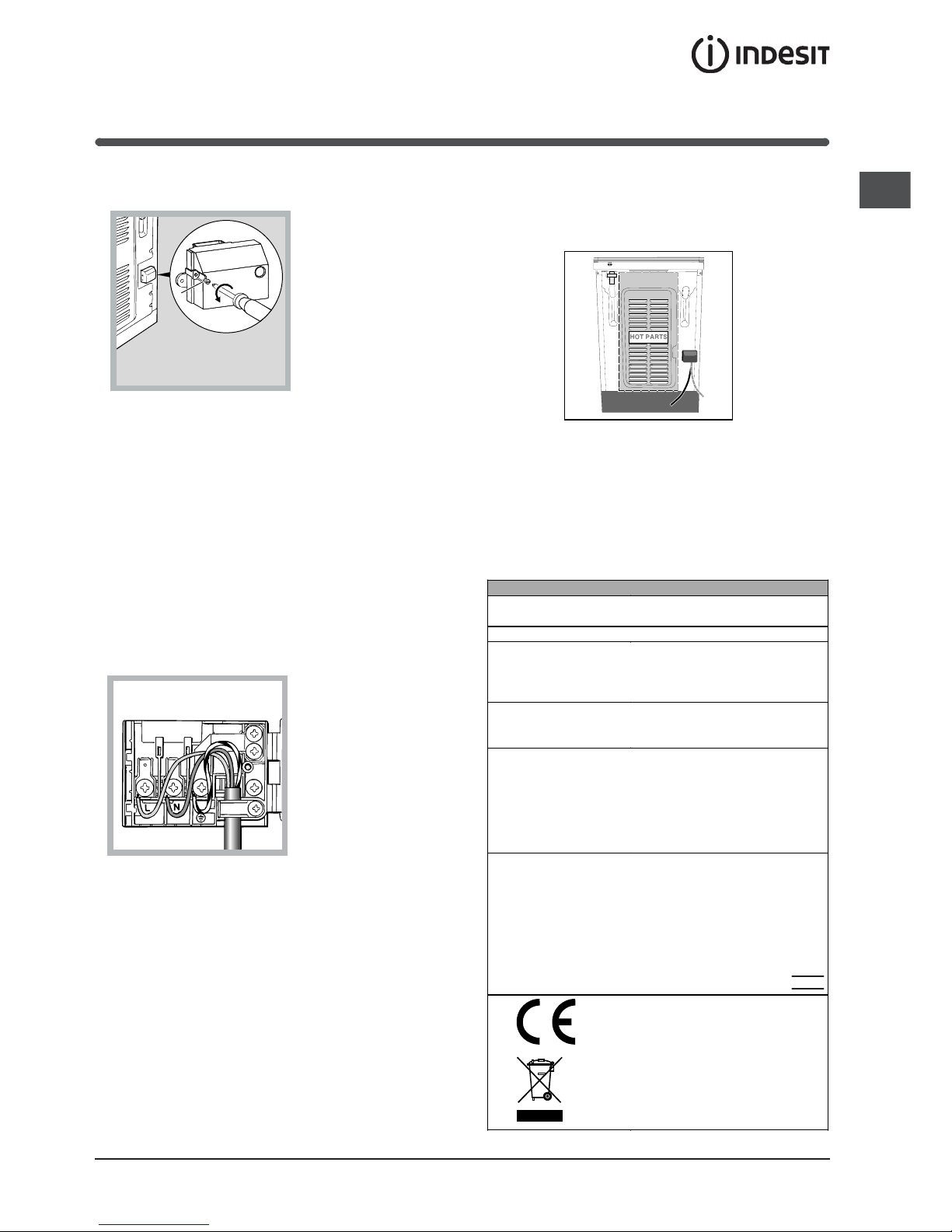
TECHNICAL DATA
Oven dimensions
(HxWxD)
34x39x44 cm
Volume
58 l
Useful
measurements
relating to the oven
compartment
width 42 cm
depth 44 cm
height 23 cm
Power supply
voltage and
frequency
see data plate
Electric hob
Front left
Back left
Back right
Front right
Maximum absorption
of the electric hob
1200 W
1700 W
1200 W
1700 W
5800 W
ENERGY LABEL
Directive 2002/40/EC on the
label of electric ovens.
Standard EN 50304
Energy consumption for Natural
convection – heating mode:
Traditional mode;
Declared energy consumption
for Forced convection Class –
heating mode: Convection
EC Directives: 2006/95/EC
dated 12/12/06 (Low Voltage)
and subsequent amendments 04/108/EC dated 15/12/04
(Electromagnetic Compatibility)
and subsequent amendments 93/68/EEC dated 22/07/93 and
subsequent amendments 2002/96/EC.
l Unscrew screw V (see fig. A)
l Pull and open the junction blok lid
Fig. A
! The wires in the mains lead are coloured in
accordance with the following code:
Green & Yellow Earth
Blue Neutral
Brown Live
As the colours of the wires in the mains lead may
not correspond with the coloured markings
identifying the terminals in your plug, proceed as
follows:
Green & Yellow wire to terminal marked E or 6 or
coloured Green or Green & Yellow.
Brown wire to terminal marked L or coloured Red.
Blue wire to terminal marked N or coloured Black
(see fig. B).
l fix the feeding cable
in the special cable
stop and close the
cover.
Fig. B
Connecting the supply cable to the mains
WARNINGS: THIS APPLIANCE MUST BE
EARTHED.
The cooker must be connected to the mains by a
switched (double pole) cooker outlet correctly fused
with a capacity appropriate to that shown on the
cooker Rating Plate. All electrical wiring from the
consumer unit to the cooker, via the switched double
pole cooker outlet, must be of an acceptable type
and current rating as above.
V
HOT PARTS
the supply cable must be positioned so that it
never reaches at any point a temperature 50°C higher
than the room temperature. The cable must be routed
away from the rear vents.
4
GB
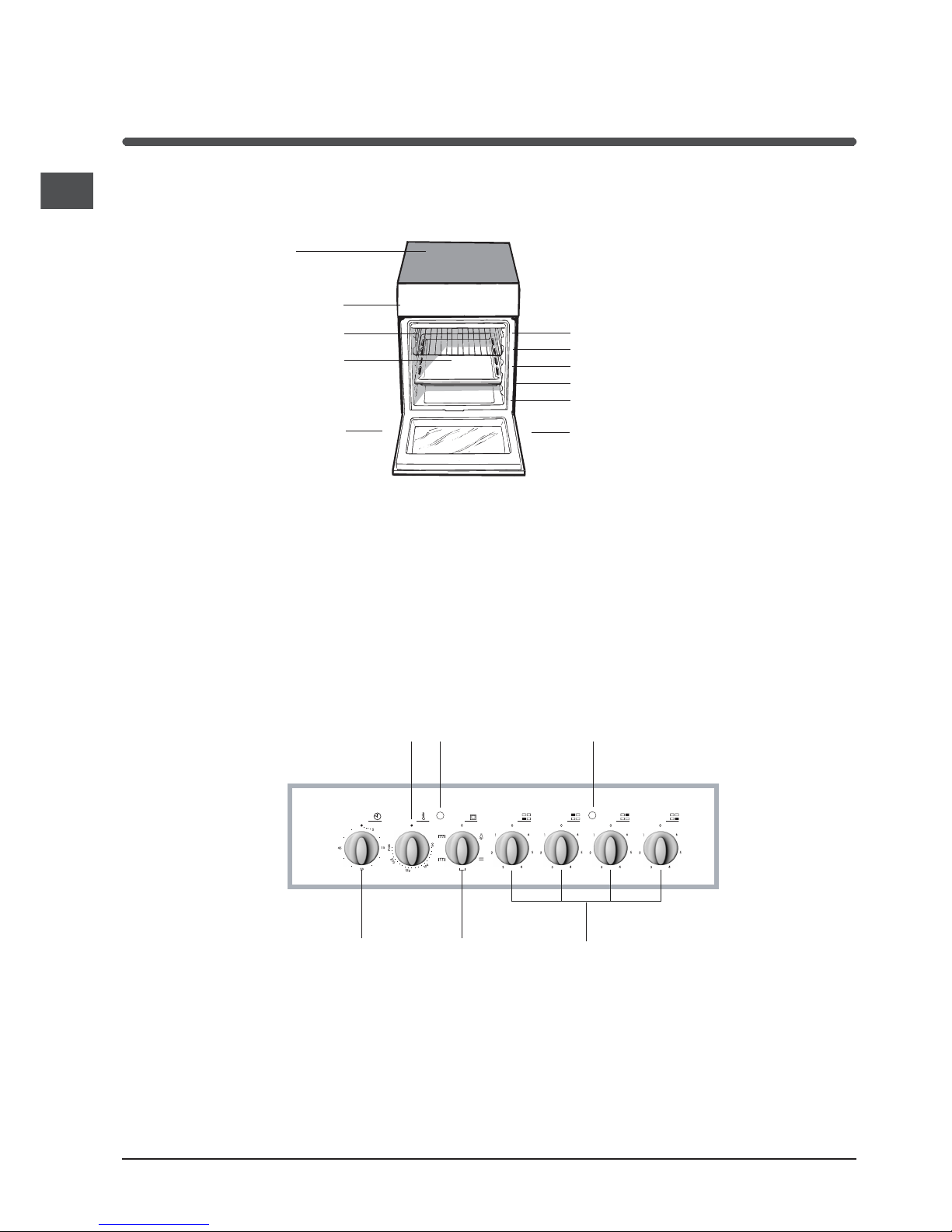
Description of the appliance
Overall view
Control panel
SELECTOR
knob
ACTIVE HOTPLATE
indicator light
ELECTRIC HOTPLATE
control knobs
THERMOSTAT
knob
THERMOSTAT
indicator light
COOKING TIMER*
knob
Control panel
GRILL rack
Glass
ceramic hob
DRIPPING pan
GUIDE RAILS
for the sliding racks
position 3
position 2
position 1
Adjustable foot
Adjustable foot
position 5
position 4
* Only on certain models
 Loading...