

Page 1

Cooker
K1G2/R
Installation and use
Êóõoííaя плита
Установка и пользование
Aragaz
Instalare ºi utilizare
K1G20/R
Page 2
Cooker with gas oven
Instructions for installation and use
Газовая плита
Инструкции по установке и эксплуатации
Aragaz cu cuptor pe gaz
Instrucþiuni pentru instalare ºi utilizare
3
13
23
Page 3

Important safety warnings
T o maintain the EFFICIENCY and SAFETY of this appliance, we recommend:
• call only the Service Centers authorized by the manufacturer
• always use original Spare Parts
1 This appliance is intended for nonprofessional use within the home.
2 These instructions are only for those countries whose symbols appear in the
booklet and on the serial no. plate of the appliance.
3 This owner’s manual is f or a class 1 appliance (insulated) or
class 2, subclass 1 appliances (installed between two cabinets.
4 Before using your appliance, read the instructions in this owner’s manual carefully
since it provides all the information you need to ensure safe installation, use and
maintenance. Always keep this owner’s manual close to hand since you may
need to refer to it in the future.
5 When you have removed the packing, check that the appliance is not damaged.
If you have any doubts, do not use the appliance and contact your nearest
Ariston Service Centre. Never leave the packing components (plastic bags,
polystyrene foam, nails, etc.) within the reach of children since they are a source
of potential danger.
6 The appliance must be installed only by a qualified technician in
compliance with the instructions provided. The manufacturer declines all liability for improper installation, which may result in
personal injury and damage to property.
7 The electrical safety of this appliance can only be guaranteed if
it is correctly and efficiently earthed, in compliance with regulations on electrical safety. Alwa ys ensure that the earthing is efficient. If y ou ha ve an y doubts, contact a qualified technician to
check the system. The manuf acturer declines all liability for damage resulting from a system which has not been earthed.
8 Before plugging the appliance into the mains, check that the
specifications indicated on the date plate (on the appliance and/
or packaging) correspond with those of the electrical and gas
systems in your home.
9 Check that the electrical capacity of the system and sockets will
support the maximum power of the appliance, as indicated on
the data plate. If you ha ve an y doubts, contact a qualified technician.
10 An omnipolar switch with a contact opening of at least 3 mm or
more is required for installation.
11 If the socket and appliance plug are not compatible, have the
socket replaced with a suitable model b y a qualified technician,
who should also check that the cross-section of the sock et cable is sufficient for the power absorbed by the appliance. The
use of adaptors, multiple sock ets and/or extensions , is not recommended. If their use cannot be avoided, remember to use
only single or multiple adapters and extensions which comply
with current safety regulations. In these cases, never exceed
the maximum current capacity indicated on the individual adaptor or extension and the maximum pow er indicated on the multiple adapter.
12 Do not leave the appliance plugged in if it is not in use. Switch
off the main switch and gas supply when you are not using the
appliance.
13 The openings and slots used for ventilation and heat dispersion
must nev er be covered.
14 The user must not replace the supply cable of this appliance. Always contact an
after-sales service centre which has been authorised by the manufacturer if the
cable has been damaged or needs replacement.
15 This appliance must be used for the purpose for which it was expressly designed.
Any other use (e.g. heating rooms) is considered to be improper and conse-
16 A number of fundamental rules must be followed when using electrical appliances.
17 Always unplug the appliance from the mains or switch off the
18 If you are no longer using an appliance of this type, remember
19 To avoid accidental spillage do not use cookware with uneven
20 Never use flammable liquids such as alcohol or gasoline, etc.
21 When using small electric appliances near the hob, keep the
22 Make sure the knobs are in the “•”/”¡” position when the appli-
23 When the appliance is in use, the heating elements and some
24 Gas appliances require regular air exc hange to ensure trou-
25 The glass top (only on certain models) can shatter if it is over-
26 If the cooker is placed on a pedestal, take the necessary
27 Warning: never place hot containers or items and
quently dangerous. The manufacturer declines all liability for damage resulting
from improper and irresponsible use.
The following are of particular importance:
• Do not touch the appliance when your hands or feet are
wet.
• Do not use the appliance barefooted.
• Do not use extensions, but if they are necessary, caution
must be ex ercised.
• Never pull the power supply cable or the appliance to unplug the appliance plug from the mains.
• Never lea ve the appliance e xposed to atmospheric agents
(rain, sun etc.)
• Do not allow children or persons who are not familiar with
the appliance to use it, without supervision.
main switch before cleaning or carrying out maintenance.
to make it unserviceable by unplugging the appliance from the
mains and cutting the supply cable. Also make all potentially
dangerous parts of the appliance safe, above all for children
who could play with the appliance.
or deformed bottoms on the burners. Turn the handles of pots
and pans inwards to avoid knoc king them ov er accidentally.
near the appliance when it is in use.
supply cord awa y from the hot parts.
ance is not in use.
parts of the oven door become extremely hot. Make sure you
don’t touch them and keep children well aw a y.
ble-free performance. When installing the cooker , follow the
instructions provided in the paragraph on “P ositioning” the
appliance.
heated. Therefore , all of the burners or hot plates must be turned
off before the top is closed.
precautions to prevent the same from sliding off the pedestal
itself.
flammable materials inside the dishwarmer drawer .
3
Page 4
Installation
All instruction on the following pages must be carried out
by a competent person (corgi registered) in compliance
with gas safety (installation and use) regulation 1984.
Important: disconnect the cooker from the electrycity
and gas supply when any adjustment, etc.
Positioning your appliance
Y our cook er is designed with a degree of protection against
overheating in class X; the appliance can therefore be
installed next to cabinets, provided the height does not
exceed that of the hob. The wall touching the bac k panel of
the cooker should be non-inflammable. Remember that
during use, the back panel of the cooker ma y reach a temperature up to 50°C above that of the room temperature .
Important: this appliance may be installed and used only
in permanently ventilated rooms in compliance with current
directives. The following precautions should be taken:
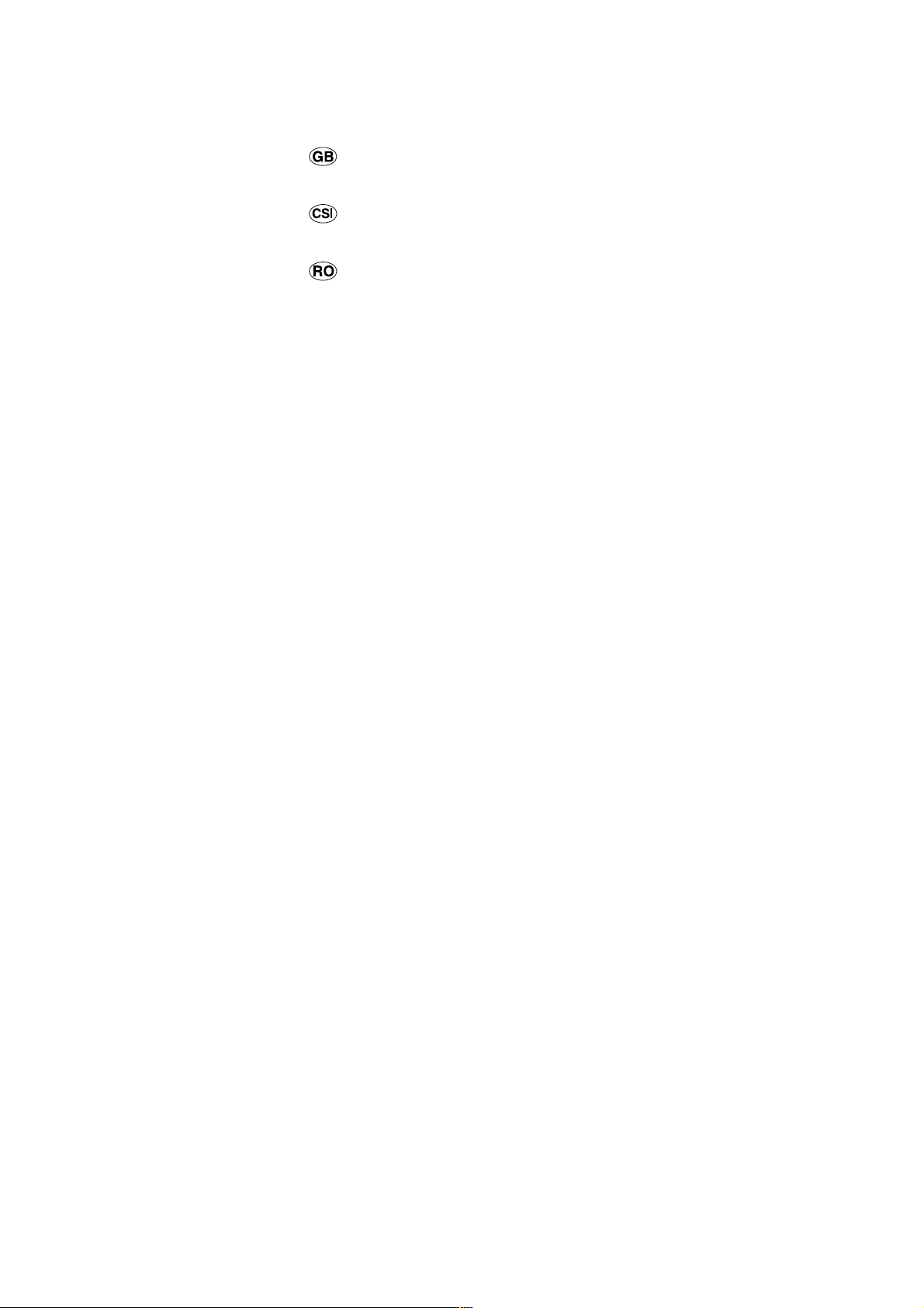
a) The room must be provided with an external exhaust
system obtained with a hood or with an electric
ventilator that goes on automatically each time the unit
is switched on.
d) The liquefied petroleum gases, which are heavier than
air, stagnate tow ards the ground. Theref ore, the rooms
containing LPG cans must have openings tow ards the
outside in order to allow the venting from the ground of
eventual gas leak. Thus, the LPG cans must not be
installed or settled in rooms that are below the ground
level, (cellar, etc.) whether the cans are empty or
partially full. It is advisable to keep in the room only the
can which is being used, and it must be placed away
from direct heat sources (ovens, fireplaces, stoves,
etc.) that could make the can reach temperatures
higher than 50°C.
Levelling your appliance (only on a fe w models)
Y our cook er is supplied with feet for le velling the appliance.
If necessary , these feet can be screwed into the housings
in the corners of the cooker base.
In the case of chimneys or flues Directly to the
with branches (for cookers) exterior
b) The room must be provided with a system for air inflow
which is necessary for a regular combustion. The air
flow necessary for the combustion should be at least 2
m3/h for kW of installed power. The system may be
realized by drawing the air directly from outside the
building through a pipe that has at least a 100 cm
useable section and which must not be accidently
obstructed (Fig. A). And further it may be realized
indirectly from other adjacent rooms which are provided
with a ventilation pipe for the e xpulsion of the fumes to
the outside of the building as foresaid, and which must
not be part of the building in common use or rooms
with risk of fire, or bedrooms (Fig. B).
Detail A Adjacent Room to
room be ventilated
A
Fig. A Fig. B
Examples of ventilation openings Increased opening between
for the comburent ai r the door and and floor
c) During prolonged use of the appliance you may
consider it necessary to open a window to the outside
to improve ventilation.
Mounting the legs (only on a few models)
Press-fit legs are supplied which fit under the base of your
cooker.
2
Installation of the cooker
The appliance can be installed next to furniture units which
are no taller than the top of the cooker hob. The wall in
direct contact with the back panel of the cooker must be
made of non-flammable material. During operation the
back panel of the cooker could reach a temperature of
50°C above room temperature. For proper installation of
the cooker, the following precautions must be taken:
a) The appliance can be placed in a kitchen, dining room
or bedsit, but not in a bathroom.
b) All furniture around the appliance must be placed at
least 200 mm from the top of the cooker, should the
surface of the appliance be higher than the worktop of
this furniture. Curtains should not be placed behind
the cooker or less than 200 mm away from the sides
of the appliance.
c) Any hoods must be installed according to the require-
ments in the installation manual for the hoods themselves.
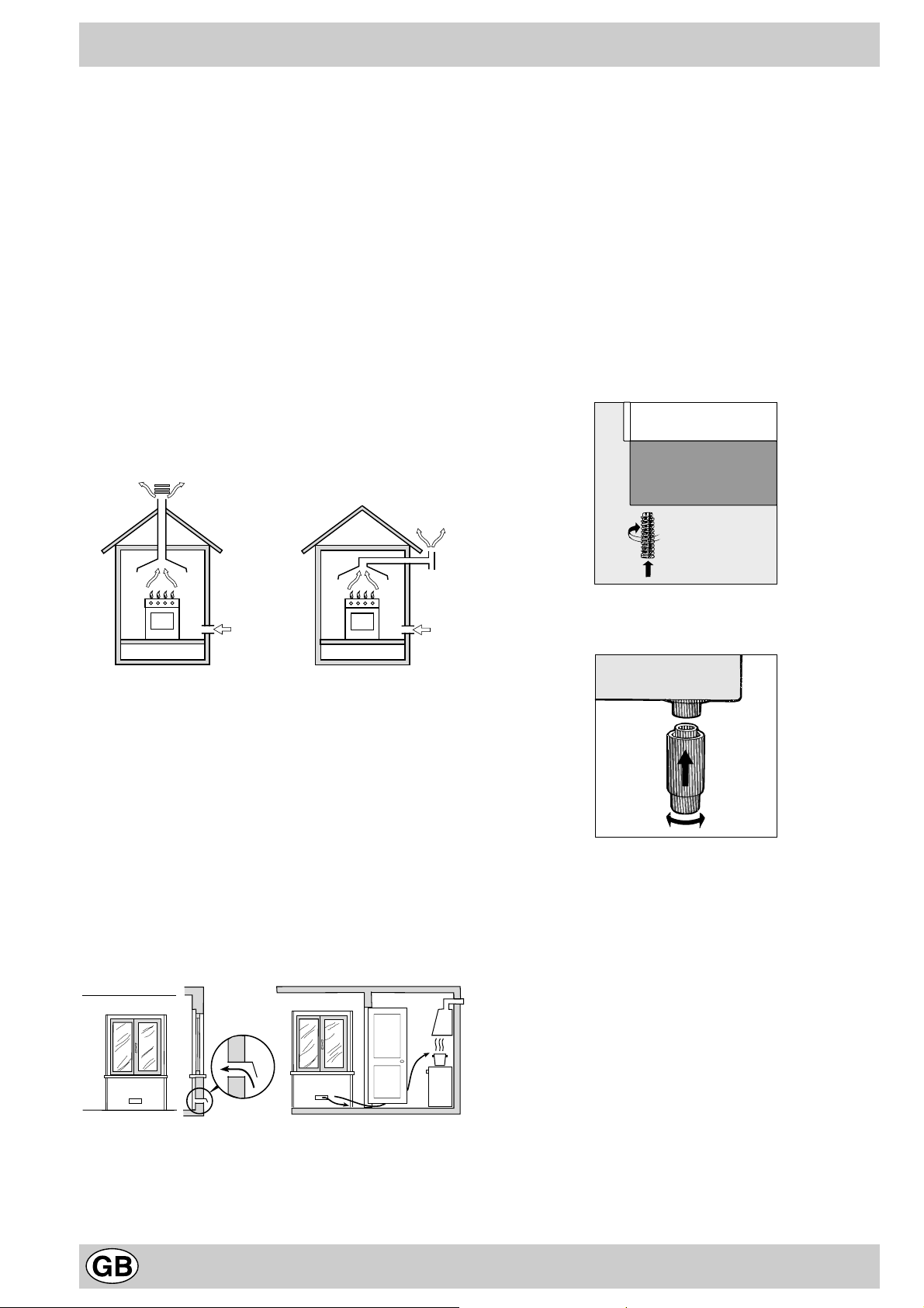
d) If the cooker is installed beneath a wall cabinet, the
latter must be situated at a minimum of 420 mm above
4
Page 5
the hob. The minimum distance between the worktop
and kitchen units made of combustible material is 700
mm.
HOOD
Min. mm.
600
mm.
420
Min.
mm. with hood
420
650
Min. mm.
min.
mm. without hood
700
min.
e) The wall in direct contact with the back panel of the
cooker must be made of non-flammable materials.
Connecting the gas
The appliance should be connected to the mains or to a
gas cylinder in compliance with current directives. Bef ore
making the connection, check that the cooker is regulated
for the gas supply you are using. If not, follow the
instructions indicated in the paragraph “Adapting to
different types of gas”. On some models the gas supply
can be connected on the left or on the right, as necessary;
to change the connection, reverse the position of the hose
holder with that of the cap and replace replace the gasket
(supplied with the appliance). When using liquid gas from
a cylinder, install a pressure regulator which complies with
current directive.
Important: check that the supply pressure complies with
the values indicated in table 1 “Characteristics of the
burners and nozzles” since this will ensure saf e operation,
correct consumption and ensure a longer life to your
appliance.
Connection with hose
Make the connection using a gas hose complying with
the the characteristics provided in current directive. The
internal diameter of the pipe used is as follows:
- 8mm for liquid gas;
- 13mm for methane gas.
When installing the hose, remember to take the following
precautions:
• No part of the hose should touch parts whose tempe-
rature exceeds 50°C;
• The length of the hose should be less than 1500 mm;
• The hose should not be subject to twisting or pulling,
and should not have bends or kinks.
• The hose should not touch objects with sharp edges,
any moving parts, and it should not be crushed;
• The full length of the hose should be easy to inspect in
order to check its condition;
Check that the hose fits firmly into place at the two ends
and fix it with clamps complying to current directive.If any
of the above recommendations can not be adopted, fle xible
metal pipes should be used.
Should the cooker be installed according to the conditions
of Class 2, subdivision 1, only a flexible metal pipe which
is in compliance with current safety standards should be
used to make the connection to the gas mains.
Connecting a flexible jointless stainless steel pipe to
a threaded attachment
Remove the hose holder fitted on the appliance. The gas
supply pipe fitting is a threaded 1/2 gas cylindrical male
attachment. Only pipes and gaskets complying with current
directives. The full length of the pipe must not exceed 2000
mm.
Tight control
Important: when installation has been completed, check
the pipe fitting for leaks with a soapy solution. Ne ver use a
flame. Once the connection has been made, ensure that
the flexible metal tube does not touch any moving parts
and is not crushed.
Connecting the supply cable to the mains
Install a normalised plug corresponding to the load
indicated on the data plate. When connecting the cable
directly to the mains, install an omnipolar circuit-breaker
with a minimum contact opening of 3 mm between the
appliance and the mains. The omnipolar circuit breaker
should be sized according to the load and should comply
with current regulations (the earth wire should not be
interrupted by the circuit breaker).
The supply cable should be positioned so that it does not
reach a temperature of more than 50°C with respect to
the room temperature, along its length. Before making the
connection, check that:
• the limiter valve and the home system can support the
appliance load (see data plate);
• the mains is properly earthed in compliance with
current directives and regulations;
• there is easy access to the socket and omnipolar circuit
breaker , once the hob has been installed.
N.B: never use reducers, adaptors or shunts since they
can cause heating or burning.
Adapting the cooker to different types of gas
In order to adapt the cooker to a different type of gas with
respect to the gas for which it was produced (indicated on
the label attached to the lid), follow these steps:
a) replace the hose holder mounted on the appliance with
that supplied in the bag of “cooker accessories”.
Important: the hose holder f or liquid gas is marked 8, the
hose holder for methane gas is marked 13. Alwa ys fit the
sealing gasket.
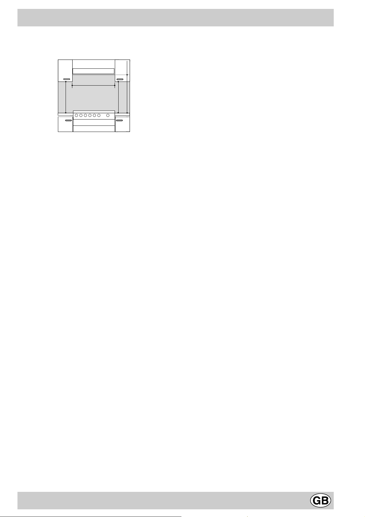
b) Replacing the burner nozzles on the hob:
• remove the grids and slide the burners from their
housings;
• unscrew the nozzles using a 7 mm socket spanner,
and replace them with nozzles for the new type of gas
(see table 1 “Burner and nozzle characteristics”).
• replace all the components by repeating the steps in
reverse order.
5
Page 6
c) Minimum regulation of the hob burners:
•
turn the tap to minimum;
• remove the knob and adjust the regulation screw, which
is positioned in or next to the tap pin, until the flame is
small but steady.
N.B.: in the case of liquid gas, the regulation screw
must be screwed in to the bottom.
• check that the flame does not turn off when you turn
the tap quickly from high to low.
d) Regulating the primary air of the burners:
The primary air of the burners requires no regulation.
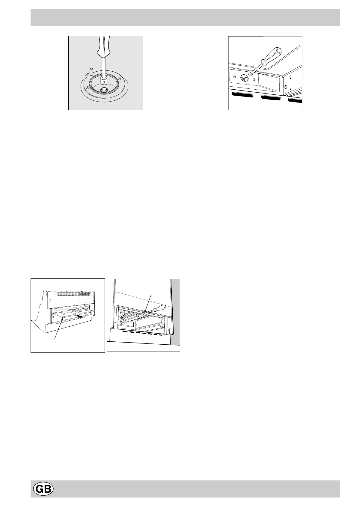
Adapting the gas oven to different types of gas
a) Replacing the oven burner nozzle:
• remove the warming drawer;
• remove the sliding protection “A” (see Fig.C);
• remove the screw and then the oven burner “V”(see
Fig. D). Remove the oven door to facilitate this
operation.
• unscrew the oven burner nozzle using the special
socket spanner for the nozzles (see Fig. E), or better
still a 7 mm socket spanner , and replace it with a nozzle
suited to the new type of gas (see table 1).
V
Fig.E
b) Minimum regulation of the oven burner without
thermostat:
• light the burner as described in the paragraph “the ov en
knob” of the instruction booklet;
• take the knob to minimum, indicated by C.
• remove the knob and turn the regulation screw which
is positioned in or next to the tap pin until the flame is
small but steady.
N.B.: in the case of liquid gas, the regulation screw
must be screwed in to the bottom;
• check that the burner does not turn off when you turn
the knob from high to low or when you open and close
the oven door quickly.
Important
On completion of the operation, replace the old rating
sticker with one indicating the new type of gas used. This
sticker is av ailab le from our Service Centres.
Note
Should the pressure of the gas used be different (or vary)
from the recommended pressure, it is necessary to fit a
suitable pressure regulator onto the inlet pipe in
compliance with current National Regulations relative to
“regulators for channelled gas”.
A
Fig. C Fig. D
6
Page 7
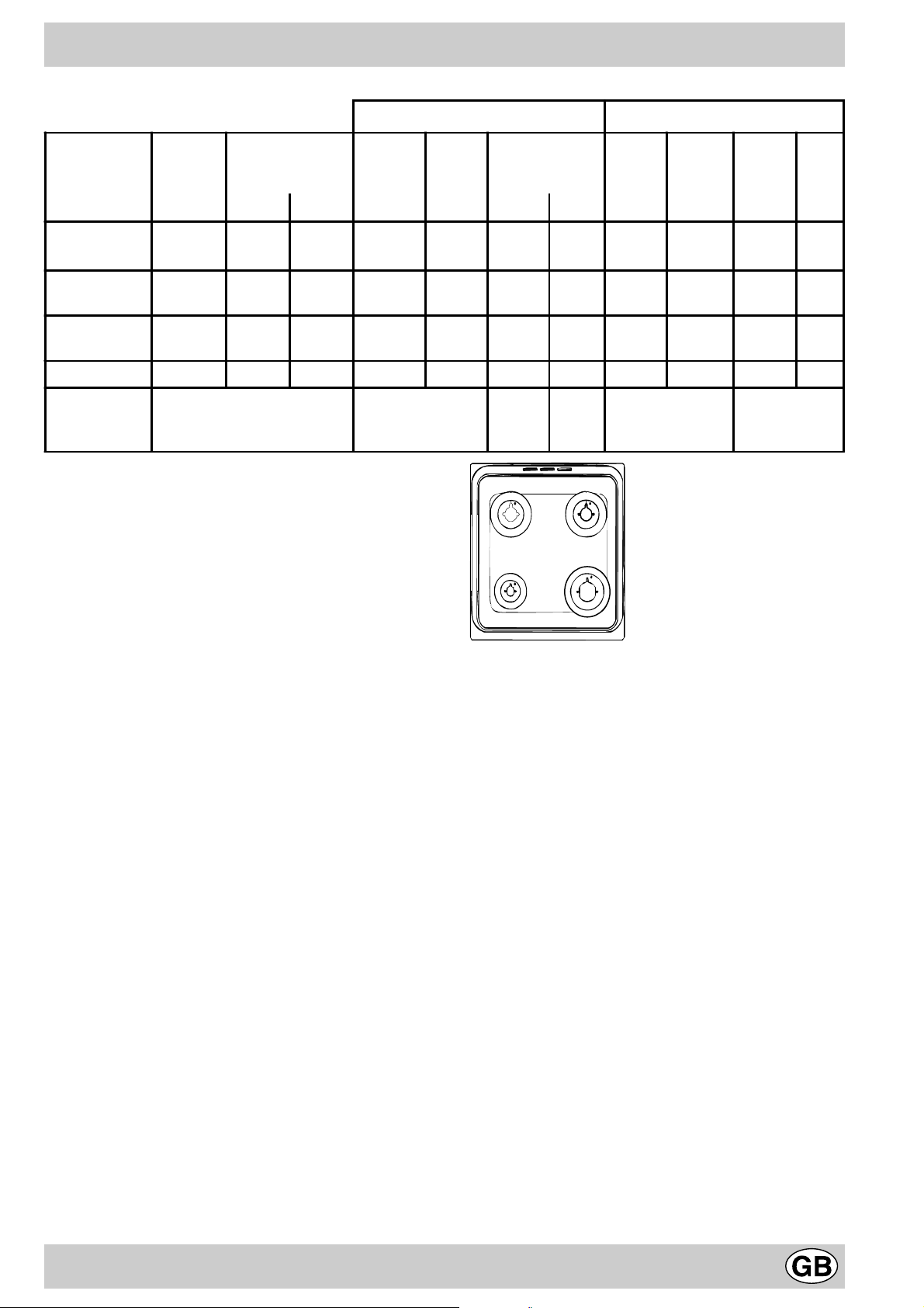
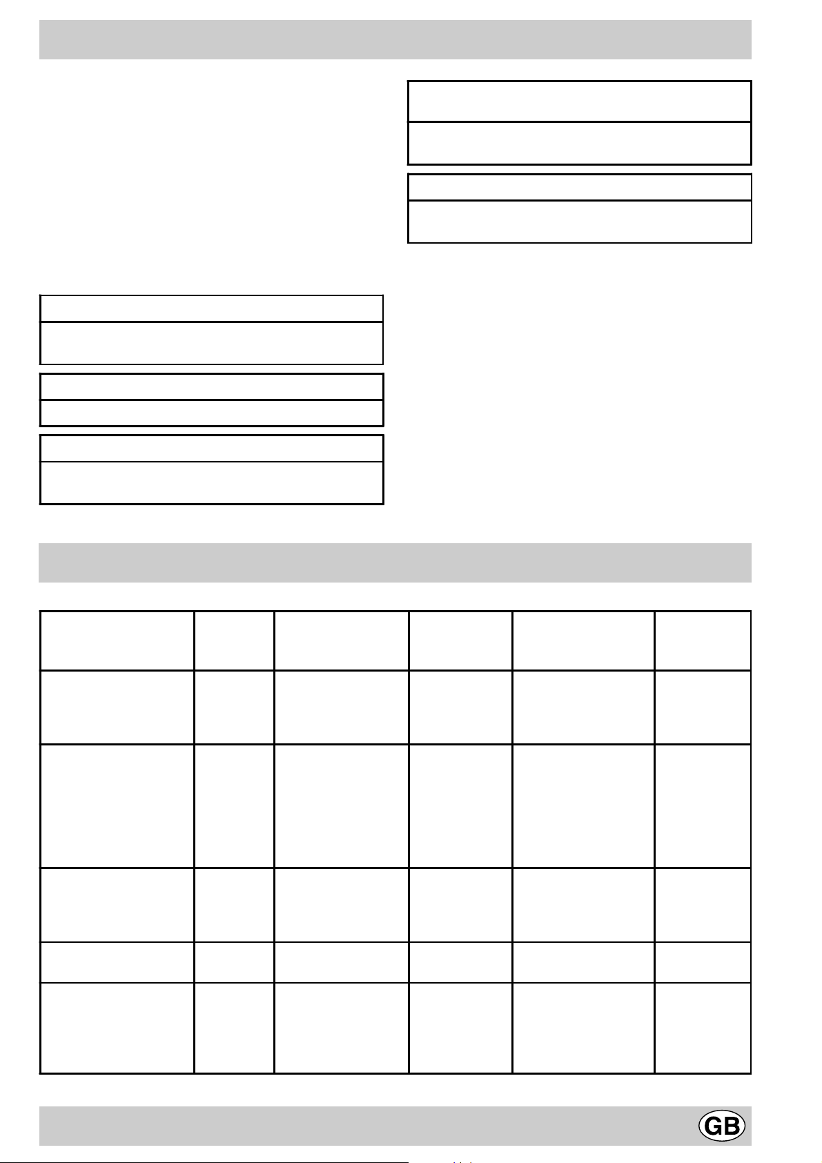
Burner and nozzle characteristics
Table 1 Liquid Gas Natural Gas
Burner Diameter
(mm)
Thermal Power
kW (p.c.s.*)
By-Pass
1/100
Nozzle
1/100
Flow*
g/h
Nozzle
1/100
Flow*
l/h
Nozzle
1/100
Flow*
Nominal Reduced (mm) (mm) *** ** (mm) (mm)
Fast
(Large)(R)
Semi Fast
(Medium)(S)
Auxiliary
(Small)(A)
100 3.00 0.7 41 87 218 214 128 286 143 286
75 1.90 0.4 30 70 138 136 104 181 118 181
51 1.00 0.4 30 52 73 71 76 95 80 95
Oven - 2.00 1.0 48-49 68 145 143 107 190 114 183
Supply
Pressures
Nominal (mbar)
Minimum (mbar)
Maximum ( mba r )
28-30
20
35
37
25
45
20
17
25
13
6,5
18
* At 15°C and 1013 mbar- dry gas
** Propane P.C.S . = 50,37 MJ/Kg
*** Butane P.C.S. = 49,47 MJ/Kg
Natural P.C .S . = 37,78 MJ/m
3
S
S
R
A
l/h
K 1G2/R
K 1G20/R
7
Page 8
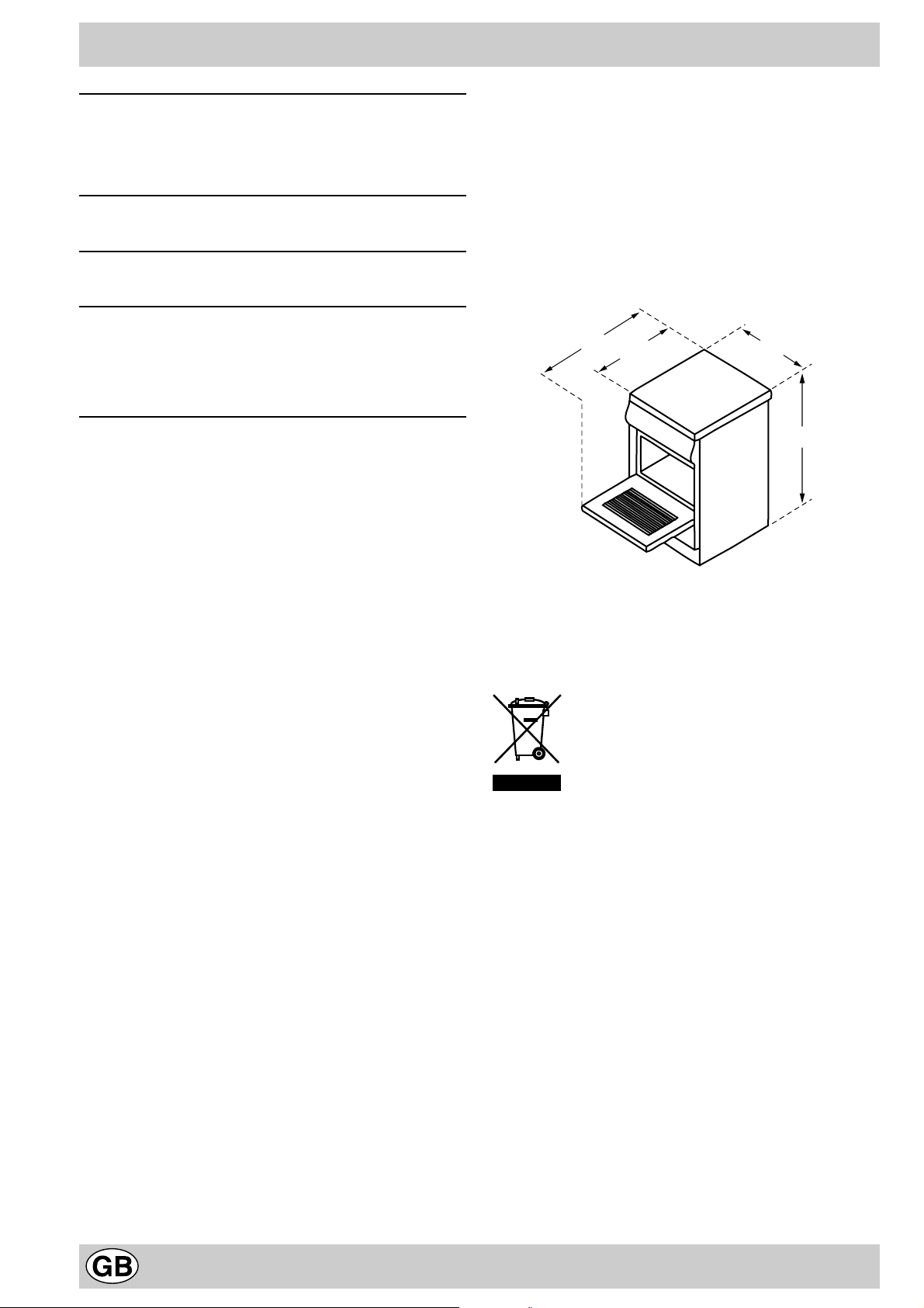
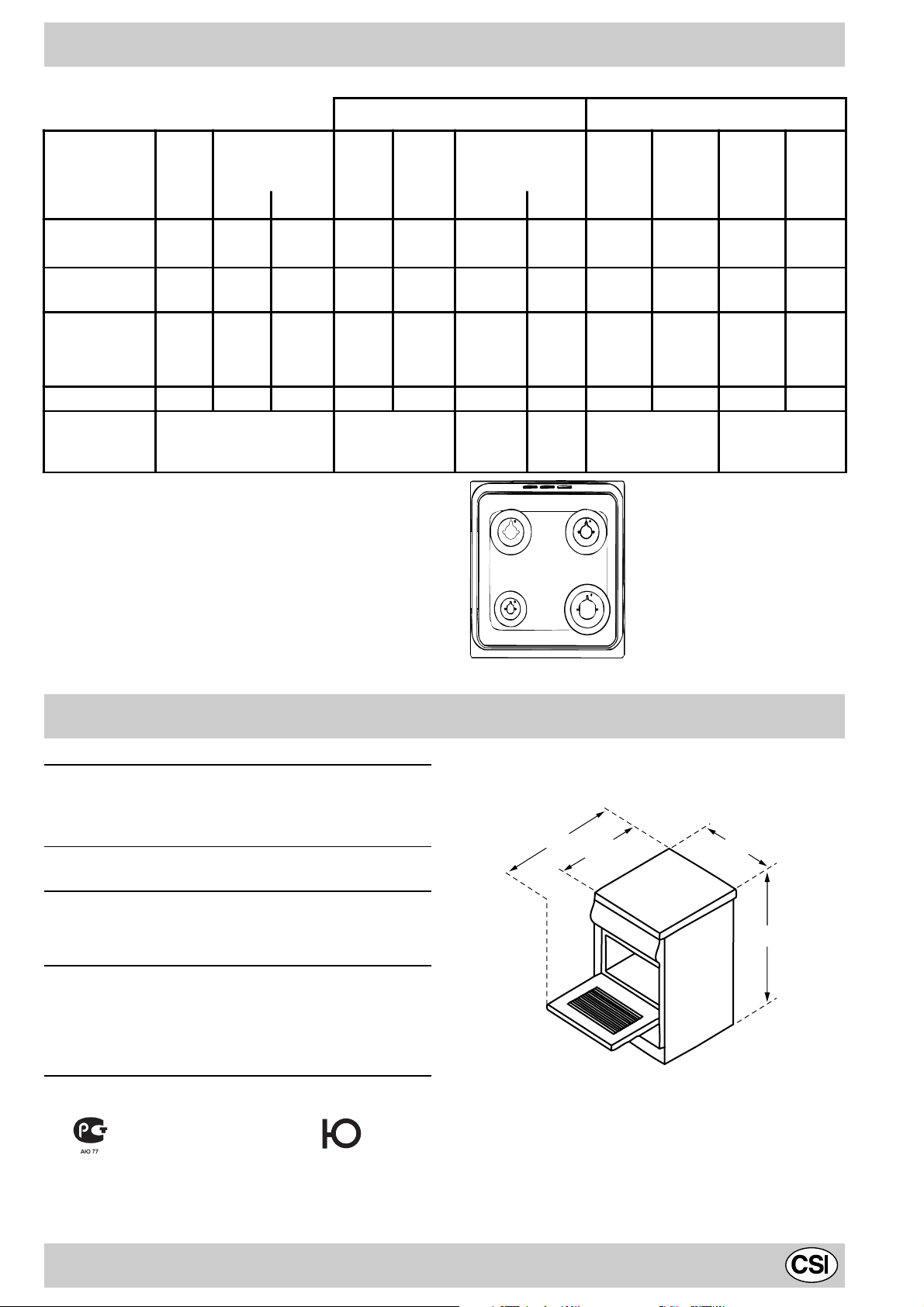
Technical Specifications
Inner dimensions of the oven:
Inner Volume of the Oven:
V oltage and Frequency of Po wer Supply:
Width: 39 cm
Depth: 38 cm
Height: 34 cm
50 lt
see data plate
Burners:
adaptable for use with all the types of gas indicated on
the data plate situated inside the flap or, once the
dishwarmer drawer has been opened, on the inside wall
of the left-hand side panel.
94
50
50
85/90
Disposal of old electrical appliances
The European Directive 2002/96/EC on Waste Electrical
and Electronic Equipment (WEEE), requires that old
household electrical appliances must not be disposed of
in the normal unsorted municipal waste stream. Old
appliances must be collected separately in order to optimise
the recovery and recycling of the materials they contain
and reduce the impact on human health and the
environment. The crossed out “wheeled bin” symbol on the
product reminds you of your obligation, that when you
dispose of the appliance it must be separately collected.
Consumers should contact their local authority or retailer
for information concerning the correct disposal of their old
appliance.
8
Page 9
F
A
E
K
G
D
B
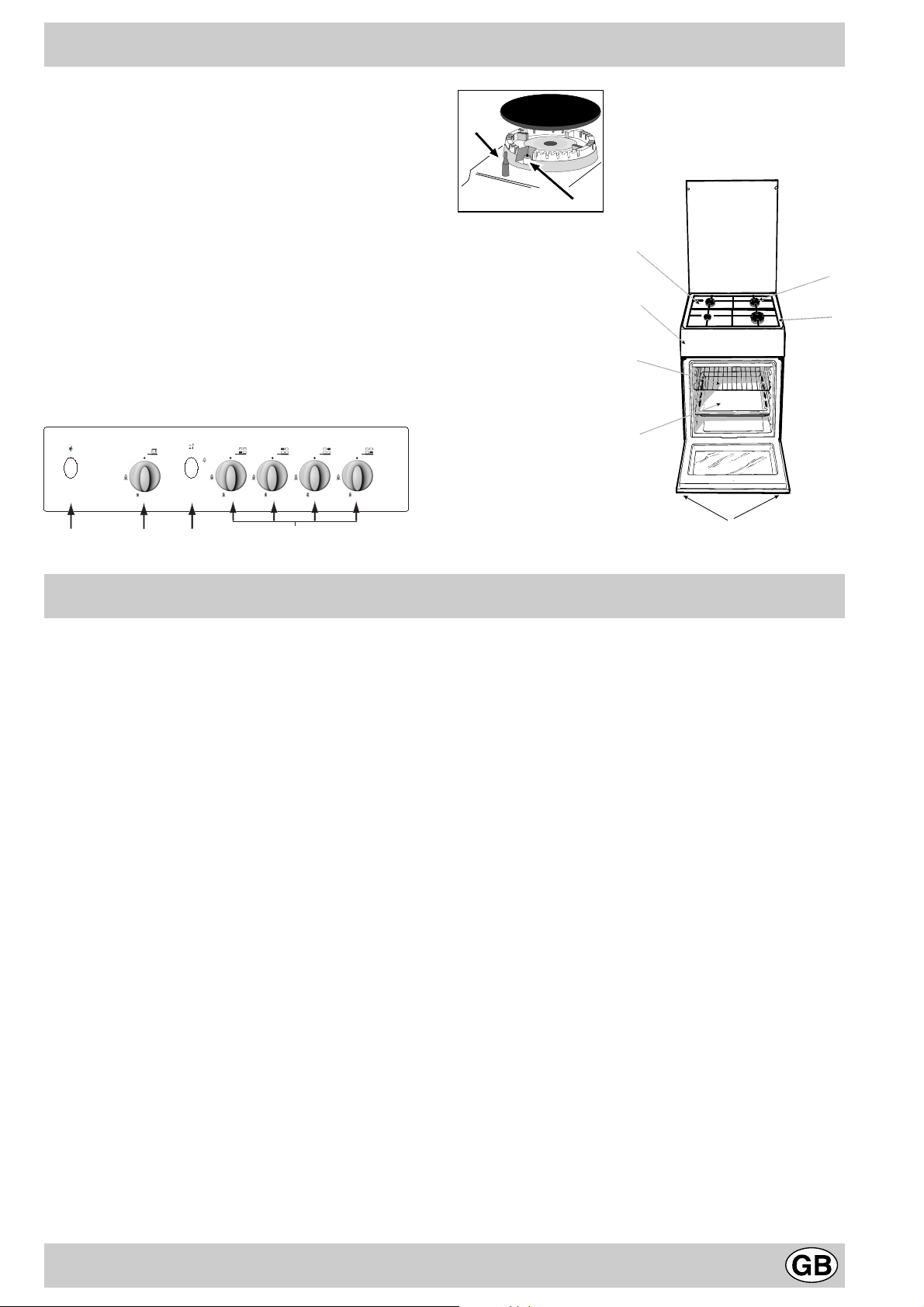
The cooker with gas oven
A. T ra y for Catching Overflows
B. Gas Burner
C. Flame Failure Device for Cooktop Burners (only a
few models)
D. T op Grate
E. Control Panel
F. Adjustable Feet or Legs
G. Dripping Pan or Baking Sheet
H. Electronic Lighting Device (only a few models)
K. Oven Rack
L. Electronic Lighting for Hob Burners (only on certain
models)
M. Oven Control Knob
N. Control Knobs for Gas Burners on Hob
O. Button for Oven Light (only a few models)
C
H
M
The different functions and uses of the oven
The various functions included in the cooker are selected
by operating the control devices located on the cooker
control panel.
Control Knobs for the Gas Burners on the Hob (N)
The position of the gas burner controlled by each one of
the knobs is shown by a symbol of a solid ring:•. To light
one of the burners, hold a lighted match or lighter near
the burner. Press down and turn the corresponding knob
in the counter-clockwise direction to the maximum E
setting. Each burner can be operated at its maximum,
minimum or intermediate power. Shown on the knob are
the different symbols for off • (the knob is on this setting
when the symbol lines up with the reference mark on the
control panel), for maximum E and minimum C.
To obtain these settings, turn the knob counter-clockwise
with respect to the off position. To turn off the burner, turn
the knob clockwise until it stops (corresponding again with
the • symbol).
Electronic Ignition for the Gas Hob (only on certain
models)
Some of the models are provided with instant electronic
lighting of the hob gas burners; these models are identified by the presence of a lighting device (see detail H).
This device operates when a slight pressure is applied to
the “L” button marked with 1 symbol. To light a specific
burner just press the button labelled “L” while pushing the
corresponding knob all the way in and turning it counterclockwise until it lights. For immediate lighting, first
press the button and then turn the knob.
Important: Should the burner flames accidentally go
out, turn off the control knob and wait at least 1 minute
before trying to relight.
Models with Hob Gas Burner Safety Devices to
Prevent Leaks (only on certain models)
These models can be identified by the presence of the
device itself (see detail C).
Important: Since the hob burners are equipped with a
safety device , you must hold the control knob in f or about
6 seconds after the burner has been lighted to allow the
gas to pass until the safety thermocouple has heated.
Notice: The first time y ou use your appliance, we recommend that you set the thermostat to the highest setting
and leave the ov en on f or about half an hour with nothing
in it, with the oven door shut. Then, open the oven door
and let the room air. The odour that is often detected during this initial use is due to the evaporation of substances
used to protect the oven during storage and until it is installed.
Attention: Only use the bottom shelf of the oven when
using the rotisserie to cook (where present). For all other
types of cooking, never use the bottom shelf and never
place anything on the bottom of the oven when it is in
operation because this could damage the enamel. Always
place your cookware (dishes, aluminium f oil, etc. etc.) on
the grate provided with the appliance inserted especially
along the oven guides.
9
Page 10
Oven Control Knob (M)
S
A
T o light the o ven burner , apply a lighted match or a lighter
to hole and while pressing in all the way set the ov en knob
on maximum E.
F
The burner can be used at maximum or intermediate
settings. These settings, maximum E and minimum C
are indicated on the knob, plus off , identified by the symbol
• and operative when this symbol points to the notch.
For the minimum to maximum settings turn the knob
counter clockwise from “Off”.
T o turn off the burner , turn the knob clockwise until it stops
(corresponding again with setting •).
Important Notice: In the event the flame f or the oven accidentally goes out, turn the control knob for the burner to
the off position and do not relight the burner for at least
one minute.
WARNING
To remove the sliding protection “A”, unscrew screw “S”.
When you have finished, replace the protection and lock
it in place with screw “S”.
Before using the oven, make sure the sliding protection
“A” is fastened in the correct position.
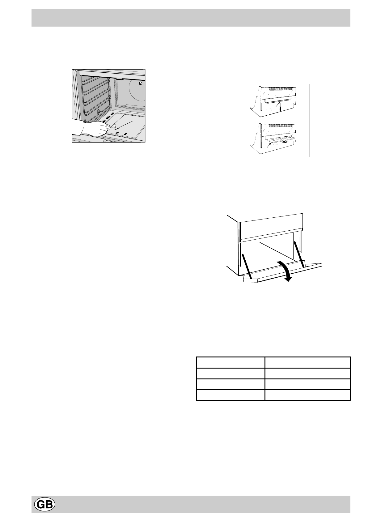
Storage recess below the oven (only a few models)
Below the oven a recess can be used to contain cooking pans
and cooker accessories. Moreover, during oven oper ation, it may
be used to keep food warm.To open the storage is necessary
turn it downwards.
Caution: this storage recess must not be used to store
inflammable materials.
Oven Light Button (O)
This button is marked by the 8 symbol and switches on
the light inside the oven so that you can monitor the cook-
ing process without opening the door.
Attention
Avoid the children touch the o v en door because it is v ery
hot during the cooking.
Practical advice for burner use
In order to get the maximum yield it is important to remember
the following:
• Use appropriate cookware for each burner (see table) so as
to avoid flames ov ershooting the edges.
• At boiling point turn the knob to minimum.
• Use cookware with lids.
• Always use cookware with flat bottoms.
Burner ø Cookware diameter (cm)
Fast (R) 24 - 26
Semi Fast (S) 16 - 20
Auxiliary (A) 10 - 14
10
Page 11
Cooking advice
The oven offers a wide range of alternatives which allow
you to cook any type of food in the best possib le wa y . With
time you will learn to make the best use of this versatile
cooking appliance and the following directions are only a
guideline which may be varied according to your o wn personal experience.
Baking cakes
The oven should alwa ys be warm before putting in cak es
wait till the end of preheating (about 10-15 min.). Cakebaking temperatures are normally around 160°C/200°C.
Do not open the oven door during the baking process as
this could cause the cake to sink.In general:
Pastry is too dry
Increase the tem peratur e by 10°C and r educ e the
cooking time.
Pastry dropped
Use less liquid or lower the t emperat ure b y 10°C.
Pastry is too dark on top
Place it on a lower rack, lower the temperature, and
increase the cooking time.
Cooked well on the inside but sticky on the
outside
Use less liquid, lower t he tem perat ure, and incr ease
the cooking time.
The pastry sticks to the pan
Grease the pan w ell and s prink le it wit h a d ustin g of
flour.
Cooking fish and meat
When cooking white meat, fowl and fish use low
temperatures. (150°C-175°C). When red meat must be
superficially well-cooked but succulent inside, it is
advisable to start with a high temperature (200-220°C)
for a short time, and then to reduce it at a later point.
Generally speaking, the more meat there is, the lower the
temperature and the longer the cooking time should
be.Place the meat in the centre of the grid and put a spilltray underneath to catch grease drips. Insert the grid so
that it is in the middle of the oven. If more heat from below
is required, use the 1° bottom shelf.
Food to be cooked
Pasta
Lasagne
Cannelloni
Pasta bakes au grati n
Meat
Veal
Chicken
Duck
Rabbit
Pork
Lamb
Fish
Mackerel
Dentex
Trout baked in paper
Pizza
Neapolitan
Cooking advice
Wt.
(Kg)
2.5
2.5
2.5
1.7
1.5
1.8
2.0
2.1
1.8
1.1
1.5
1.0
1.0 3 220 15 15-20
Cooking position
of shelves from
bottom
3
3
3
3
3
3
3
3
3
3
3
3
Temperature
(°C)
210
200
200
200
220
200
200
200
200
180-200
180-200
180-200
Pre-heating time
(min)
10
10
10
10
10
10
10
10
10
10
10
10
Cooking time
(min.)
60-75
40-50
40-50
85-90
90-100
100-110
70-80
70-80
90-95
35-40
40-50
40-45
Cake
Biscuits
Tarts
Savoury pie
Raised Cakes
cooking times are appr oxim ate and m ay va ry accor ding to personal taste.
NB:
0.5
1.1
1.0
1.0
3
3
3
3
11
180
180
180
165
15
15
15
15
30-35
30-35
45-50
35-40
Page 12

Cooker routine maintenance and cleaning
Before each operation, disconnect the cooker from the
electricity .T o assure the long lif e of the cooker , it must be
thoroughly cleaned frequently , keeping in mind that:
• Do not use steam equipment to clean the appliance .
• the enamelled parts and the self-cleaning panels are
washed with warm water without using any abrasive
powders or corrosive substances which could ruin
them;
• the inside of the oven should be cleaned fairly often
while it is still warm using warm water and detergent,
followed by careful rinsing and drying;
• the flame spreaders should be w ashed frequently with
hot water and detergent taking care to eliminate any
scale;
• in cookers equipped with automatic lighting, the
terminal part of the electronic instant lighting devices
should be cleaned frequently and the gas outlet holes
of the flame spreaders should be checked to make
sure they are free of any obstructions;
• the electric plates are cleaned with a damp cloth and
they should be lubricated with a little oil while they still
warm;
• Stainless steel may become mar ked if it comes into
contact with very hard water or harsh detergents
(containing phosphorous) for long periods of time. After
cleaning, it is advisable to rinse thoroughly and dry. It
is also recommended to dry any water drops;
• On models with glass covers, the covers should be
cleaned with hot water; the use of rough cloths or
abrasives is to be av oided.
N.B: avoid closing the cover while the gas burners
are still warm. Remove any liquid from the lid before
opening it.
Important: per iodically check the wear of the gas hose
and substitute it if there are any defects; we recommended
changing it every year .
Replacing the oven lamp
• Unplug the oven from the mains;
• Remove the glass cover of the lamp-holder;
• Remove the lamp and replace with a lamp resistant to
high temperatures (300°C) with the following
characteristics::
- V oltage 230V
- Wattage 25W
- Type E14
• Replace the glass cover and reconnect the oven to the
mains.
Greasing the T aps
The taps may jam in time or they may become difficult to
turn. If so , the tap itself must be replaced.
N.B.: This operation m ust be performed by a technician
authorised by the manufacturer .
Removing the lid
The cooker lid can be remov ed to f acilitate cleaning. To
remove the lid, first open it completely and pull it
upwards (see figure)
12
Page 13

Безопасность хорошая привычка
1. Это оборудование разработано для использования внут-
ри помещений. Ни при каких обстоятельствах не исполь-
зуйте оборудование на улице.
2. Плита должна использоваться в домашних условиях для
приготовления и разогрева пищи в соответствии с дан-
ной инструкцией. Использование оборудования не по на-
значению, а также промышленное использование,
использование плиты в офисах, предприятиях сферы об-
служивания, здравоохранения, просвещения и т.п. не пре-
дусмотрено. Производитель не несет ответственности за
выход из строя оборудования при нарушении данного пун-
кта инструкции.
3. Данная инструкция относится к оборудованию класса 1
(свободная установка) и класса 2 подкласса 1 (установка
между двумя шкафами).
4. Снимите упаковку; элементы упаковки (пластиковые па-
кеты, пенопласт, металлические скрепки) могут быть по-
тенциально опасны для детей, поэтому выбросьте
упаковку сразу же или уберите в недоступное место.
5. Убедитесь, что Ваша плита не повреждена и полностью
укоплектована. Если у Вас есть сомнения, свяжитесь с
продавцом немедленно.
6. Запрещено использование удлинителей и переходников.
Длина кабеля не должна превышать 1,5 м. Производитель
не несет ответственности за возгорания, произошедшие
из-за использования тройников и удлинителей, а также со-
единительного кабеля, сечение которого не соответствует
потребляемой оборудованием мощности. При установке
необходимо проверить соответствие характеристик сети
и плиты. Необходимые сведения содержатся в специаль-
ной таблице на задней стороне плиты.
7. Розетка и вилка должны быть одного типа.
8. Плита должна устанавливаться только квалифицирован-
ным персоналом, в соответствии с рекомендациями Про-
изводителя и стандартами, действующими на территории
стран СНГ. Неправильная установка может принести вред
людям, животным или Вашей собственности. В случае
неправильной установки Производитель снимает с себя
всякую ответственность.
9. Электрическая безопасность гарантирована только при
наличии эффективного заземления, выполненного в со-
ответствии с правилами электрической безопасности. Это
требование обязательно должно соблюдаться. Если
возникли сомнения, свяжитесь со специалистом по уста-
новке, который проверит Вашу систему заземления.
Производитель не несет ответственности за ущерб,
вызванный отсутствием заземления или его неисправно-
ñòüþ.
10. Если плита подключается непосредственно к сети (без
вилки и розетки), необходимо установить многолинейный
выключатель с расстоянием между разведенными кон-
тактами не менее 3 мм, линия заземления при этом не
должна разрываться. Выключатель должен устанавли-
ваться в легкодоступном месте.
11. Всегда вынимайте вилку из розетки или отключайте элек-
тричество на Вашем щитке перед мойкой или другими
операциями по профилактике плиты.
12. Не тяните провод, чтобы вынуть вилку из розетки: это
очень опасно. Не пережимайте и не натягивайте сетевой
кабель. Для замены поврежденного кабеля вызывайте
специалиста из обслуживающей организации.
13. Следите за тем, чтобы вентиляционные отверстия и щели
в задней части плиты и под панелью управления не были
закрыты, в противном случае возникает опасность пре-
вышения рабочей температуры электрической изоляции
и короткого замыкания.
14. Ваша плита должна использоваться только для того, для
чего она разработана. Если Вы решили испытать плиту
другой работой, (например, отапливать помещения) де-
лайте это на свой страх и риск. Производитель не несет
ответственности за поломки, вызванные ненадлежащим
или неразумным использованием.
15. Не касайтесь плиты, если Ваши руки или ноги мокрые
или сырые, не пользуйтесь оборудованием босиком.
16. В соответствии с общими требованиями Государствен-
ной Противопожарной службы не оставляйте плиту без
присмотра.
17. Не разрешайте детям и лицам, не знакомым с настоя-
щей инструкцией, пользоваться плитой в ваше отсутствие.
18. Запрещается изменение конструкции плиты и вмешатель-
ство лиц, не уполномоченных Производителем на гаран-
тийный ремонт.
19. При использовании малых кухонных электроприборов
рядом с плитой следите, чтобы их питающие кабели не
касались горячих частей оборудования.
20. Отключайте плиту от сети, когда уезжаете надолго. Пере-
кройте подачу газа.
21. Не используйте легковоспламеняющиеся жидкости (ал-
коголь, бензин и т.п.) рядом с работающим оборудовани-
åì.
22. Не ставьте на плиту посуду с неровным или деформиро-
ванным дном. Старайтесь располагать посуду так, чтобы
ручки не перегревались и чтобы было невозможно
опрокинуть посуду, случайно задев за ручки.
23. Если плита не используется, проверьте, что рукоятки на
панели управления находятся в положении«
24. Не подпускайте детей к плите, когда вы пользуетесь гри-
лем или духовкой. Части плиты после выключения дол-
гое время остаются горячими. Будьте осторожны, не
прикасайтесь к плите: дождитесь, когда она полностью
остынет.
25.
Предупреждение:
- Никогда не помещайте горячую посуду и воспламеняю-
щиеся материалы в отделение для хранения и подогре-
âà.
- Никогда не оставляйте включенные газовые горелки пус-
тыми или с неиспользуемой посудой, так как посуда быст-
ро нагревается, что может повредить оборудование.
- В некоторых моделях поверхность плиты закрывается
стеклянной крышкой. Во избежание растрескивания стек-
ла не опускайте крышку на горячие конфорки.
26. Использование газовой плиты требует постоянного при-
тока воздуха. Устанавливая плиту, строго следуйте инст-
рукциям, изложенным в параграфе «Расположение»
настоящего Руководства.
27. При установке плиты на опоры, соблюдайте меры предо-
сторожности, чтобы избежать соскальзывания плиты с
îïîð.
28. При возникновении нестандартной ситуации отключите
плиту от сети, позвоните в сервисный центр, телефон ко-
торого указан в гарантийном документе (гарантийном та-
лоне, сервисной книжке, сервисном сертификате).
29. Если Вы решили, что плита больше не годится для эксп-
луатации, сделайте ее непригодной для использования:
отключите от сети, обрежьте питающий кабель, снимите
потенциально опасные части (это особенно важно для бе-
зопасности детей, которые могут играть с неиспользуе-
мыми или выброшенными приборами).
Внимание! Для обеспечения эффективной и безопасной
работы оборудования настоятельно рекомендуем:
• не пользоваться услугами лиц, не уполномоченных Произ-
водителем;
• при ремонте требовать использования оригинальных за-
пасных частей.
»/ «î».
13
Page 14

Установка
Этот раздел предназначен для квалифицированных техни-
ков и содержит инструкции по установке и обслуживанию
плиты в соответствии с действующими нормами безопасно-
ñòè.
Важно: перед любыми работами по наладке, обслужи-
ванию и т.п. отключите плиту от электрической сети.
Расположение
Важно: Плита должна устанавливаться и использоваться в
помещениях с постоянной вентиляцией, для этого необхо-
димо, чтобы соблюдались следующие требования:
à) Помещение должно иметь вентиляционную систему, до-
статочную для удаления продуктов сгорания. Это может
быть вытяжка или электрический вентилятор, который
автоматически включается при работе вытяжки.
Вытяжка при наличии дымохода Прямая вытяжка
Выравнивание плиты (толькодля некоторых
моделей)
Ваша плита снабжена регулируемыми ножками, которые
служат для ее выравнивания. При необходимости, ножки
вкручиваются в отверстия по углам основания плиты.
Установка опор (только для некоторых моделей)
Плита комплектуется надставными опорами, которые уста-
навливаются под основанием плиты.
á) Для надлежащего сгорания в помещение должен по-
ступать свежий воздух. Приток воздуха должен
составлять не менее 2 м
3
/час на каждый киловатт мощ-
ности устанавливаемого оборудования. Воздух может
поступать прямо с улицы через трубу с сечением 100
2
, конструкция которой не допускает засорения. Для
ñì
оборудования, не имеющего устройства безопасности,
которое предотвращает подачу газа при случайном
затухании горения, сечение трубы должно быть не
менее 200 см
3
(рис. А). Кроме того, воздух может
поступать из смежной комнаты (кроме спален и
пожароопасных помещений), если она имеет подобную
же приточную трубу, и конструкция двери обеспечивает
свободный проход воздуха (ðèñ. Â).
Приточное Смежное Помещение, требующее
отверстие А помещение вентиляции
A
Пример обеспечения Обеспечение зазора между дверью
притока воздуха и порогом для свободного прохода
приточного воздуха
Ðèñ. À Ðèñ. Â
â) При длительной работе плиты может потребоваться
дополнительная вентиляция, например, открытое окно
или наличие кондиционера.
ã) Сжиженный газ тяжелее воздуха, и поэтому скаплива-
ется внизу. Помещения, в которых устанавливаются
баллоны со сжиженным газом, должны быть оснащены
наружной вентиляцией, чтобы через нее мог уходить газ
в случае утечки. Нельзя устанавливать и хранить бал-
лоны с газом в помещениях, расположенных ниже уров-
ня пола (в подвалах и полуподвалах). Рекомендуем
держать в кухне только используемый баллон и уста-
навливать его подальше от источников тепла (духовок,
каминов, печей и т.п.), способных нагреть баллон до
температуры выше 50°С.
Установка плиты
Плита имеет теплоизоляцию степени X, поэтому плита не
может быть установлена непосредственно рядом с мебе-
лью, которая выше нее. Плита может соприкасаться со сте-
ной помещения и кухонной мебелью, если они способны
выдержать температуру, на 50°С превышающую комнатную.
При установке плиты необходимо соблюдать следующие
меры предосторожности:
a) Плита может быть установлена в кухне, кухне-столовой
или гостинной, но не в ванной или душевой.
á) Кухонная мебель, превышающая по высоте плиту, долж-
на стоять от нее на расстоянии не менее 110 см. Не
допускается вешать занавески непосредственно за пли-
той и на расстоянии ближе чем 110 см от ее боковых
сторон.
â) Вытяжки устанавливаются согласно их инструкциям по
по эксплуатации.
ã) Стенные шкафы можно навешивать на одной линии
с боковой плоскостью плиты, при этом расстояние от
нижней кромки шкафа до рабочей поверхности плиты
должно быть не менее 420 мм. Минимальное расстоя-
ние между плитой и кухонной мебелью, сделанной из
легковоспламеняющихся материалов, должно состав-
лять не менее 700 мм (ðèñ).
ä) Стена, соприкасающаяся с задней стороной плиты, дол-
жна быть облицована огнеупорным материалом.
14
Page 15

ПОДКЛЮчЕНИЕ ГАЗА
Подключение плиты к газу должно производиться квалифи-
цированным персоналом в соответствии с действующими
стандартами и после проверки соответствия типа подклю-
чаемого газа, тому, на который настроено оборудование. При
несоответствии типов газа, следуйте инструкциям парагра-
фа «Настройка плиты на различные типы газа».
Для некоторых моделей подвод газа может быть осуществ-
лен как с левой, так и с правой стороны. Чтобы изменить
место подключения газа, поменяйте местами штуцер и за-
глушку и замените уплотнительную прокладку (поставляет-
ся с оборудованием). Если плита подсоединяется к баллону
со сжиженным газом, отрегулирйте его давление в соответ-
ствии с действующими нормами техники безопасности, на
баллон с газом необходимо установить редуктор.
Важно: для безопасной и долгой работы оборудования, убе-
дитесь, что давление газа соответствует данным, указанным
в табл. 1 «Характеристики горелок и жиклеров».
Подключение шлангом
Подсоедините газовый шланг, характеристики которого от-
вечают национальным стандартам.
Внутренний диаметр штуцеров под шланги:
8 мм для сжиженного газа;
13 мм для метана.
При подключении шлангом соблюдайте следующие меры
предосторожности:
• Шланг по всей длине не должен касаться частей плиты,
температура которых превышает 50°С.
• Длина шланга не должна быть более 1500 мм.
• Шланг не должен быть растянут и перекручен, иметь из-
гибов и уступов.
• Шланг не должен ничем прижиматься и соприкасаться
с подвижными деталями и предметами, имеющими
острые края.
• Шланг по всей длине должен быть доступен для осмот-
ра и контроля состояния.
Проверьте плотность посадки шланга с обеих сторон и за-
фиксируйте его зажимами. Если хотя бы одно из приведен-
ных выше требований не удается выполнить, используйте
гибкие металлизированные трубы.
Если плита устанавливается по правилам, относящимся к
бытовым приборам класса 2 подкласса 1, то согласно дей-
ствующим стандартам для подключение газа должны ис-
пользоваться только гибкие металлизированные трубы.
Внимание: между газовой трубой и плитой после установки
шланга не должно быть электрического соединения.
редственно подключите оборудование к сети (без вилки и
розетки). В последнем случае должен быть установлен мно-
голинейный выключатель, соответствующий нагрузке обо-
рудования, с расстоянием между разведенными
контактами не менее 3 мм, причем линия заземления не
должна разрываться. Питающий кабель следует распола-
гать так, чтобы по всей длине он никогда не нагревался до
температуры, превышающей на 50°С комнатную.
Перед подсоединением убедитесь в том, что:
• предохранители (пробки) или автоматические выключа-
тели и проводка выдерживают ту нагрузку, которую они
уже несут и дополнительную от вновь устанавливае-
мого оборудования (см. табличку характеристик);
• заземление соответствует правилам и требованиям,
предъявляемыми к заземлению бытовой техники;
• розетка или многолинейный выключатель находятся в
легкодоступном месте.
N.B. Никогда не используйте удлинители, переходники, двой-
ные и более розетки, которые могут стать причиной пере-
грева и возгорания.
Оборудование, подключенное с нарушением требований
безопасности бытовых приборов большой мощности,
изложенных в настоящей инструкции, является потенци-
ально опасным.
Производитель не несет ответственности за ущерб здо-
ровью и собственности, если он вызван несоблюдением
указанных норм установки.
Настройка плиты на различные типы газа
Для того чтобы подготовить плиту к работе с другим типом
газа, необходимо заменить жиклеры, отрегулировать пода-
чу воздуха и минимальное пламя.
Помните, во время выполнения этих операций плита
должна быть отключена от сети.
Важно: снимите имеющийся штуцер и установите тот, кото-
рый находится в пакете принадлежностей.
Обратите внимание: штуцер для сжиженного газа марки-
рован цифрой «8», штуцер для метана и городского газа
имеет маркировку «13». Обязательно установите уплотни-
тельную прокладку.
à) Замена жиклеров верхних горелок:
• снимите решетки и выньте горелки из гнезд;
• с помощью 7 мм торцевого ключа отвинтите жиклеры и
замените их жиклерами для нового типа газа
(см. табл. 1 «Характеристики горелок и жиклеров»);
• соберите все детали в обратном порядке.
Подключение гибкой бесшовной стальной трубы
к резьбовому соединению
Удалите штуцер. Гибкая стальная труба присоединяется к
тому же выводу с наружной резьбой 1/2 дюйма. Используй-
те только трубы и прокладки, соответствующие нацио-
нальным стандартам. Полная длина трубы не должна
превышать 2000 мм. После подключения удостоверьтесь,
что гибкая стальная труба не касается движущихся пред-
метов и не пережата.
Контроль плотности подсоединения
Выполнив подключение газа проверьте наличие его утечек,
используя мыльный раствор. Никогда не используйте для
проверки пламя.
ЭЛЕКТРИЧЕСКИЕ СОЕДИНЕНИЯ
Подсоединение кабеля к сети
Оснастите питающий кабель соответствующей вилкой (см.
табличку характеристик и местные стандарты) или непос-
á) Регулировка минимального пламени верхних горелок:
• поверните рукоятку к минимальному положению;
• снимите рукоятку и вращайте ее регулировочный винт
(расположен сбоку или внутри стержня регулятора) в
разные стороны пока пламя не станет малым, но
устойчивым.
N.B. В случае с сжиженным газом регулировочный винт дол-
жен быть закручен полностью.
15
Page 16

• убедитесь, что при быстром повороте рукоятки от мак-
симального к минимальному положению пламя не гаснет.
â) Регулировка поступления воздуха в горелки:
• регулировка не требуется.
Настройка газовой духовки на другой тип газа
à) Замена жиклера горелки духовки:
• выньте отделение для хранения и подогрева;
• выдвиньте и удалите защитную панель «À» (ñì. ðèñ. C);
• открутите винт «V» (ðèñ. D) и снимите горелку для
облегчения этой процедуры снимите дверцу;
• специальным торцевым ключом для жиклеров (ðèñ. E)
или 7 мм торцевым ключом отвинтите жиклер горелки
духовки и замените его подходящим для нового типа газа
(см. таблицу 1).
V
A
á) Регулировка минимального пламени для газовой го-
релки духовки без термостата:
• зажгите горелку как описано в параграфе «Рукоятка уп-
равления газовой духовкой» инструкции;
• поверните рукоятку к минимальному положению
• снимите рукоятку и вращайте ее регулировочный винт
(расположен сбоку или внутри стержня регулятора) в
разные стороны пока пламя не станет малым, но
устойчивым.
N.B. В случае с сжиженным газом регулировочный винт дол-
жен быть закручен полностью.
• убедитесь, что при быстром повороте рукоятки от мак-
симального к минимальному положению и при резком от-
крывании и закрывании дверцы пламя не гаснет.
Важно: по завершении всех операций старую наклейку за-
мените на новую с указанием типа используемого газа
(наклейку можно приобрести в сервисном центре).
Примечание: если давление используемого газа отличает-
ся от рекомендуемого, на подводную трубу в соответствии
действующими местными стандартами необходимо устано-
вить подходящий редуктор.
C;
Ðèñ. C Ðèñ. D
Ðèñ. E
16
Page 17
Характеристики горелок и жиклеров
Таблица 1 Сжиженный газ Природный газ
Горелка
Быстрая
(большая)(R)
Полубыстрая
(средняя)(S)
Дополни-тел-
üíàÿ
(Маленькая)
(A)
Духовка - 2.00 1.0 48-49 68 145 143 107 190 114 183
Давление
* Сухой газ при 15°С и давлении 1013 мбар
** Пропан P.C.S. = 50.37 MÄæ/êã
*** Бутан P.C.S. = 49.47 MÄæ/êã
Природный газ P.C.S. = 37.78 MДж/м
Äèà-
ìåòð
(mm)
100 3.00 0.7 41 87 218 214 128 286 143 286
75 1.90 0.4 30 70 138 136 104 181 118 181
51 1.00 0.4 30 52 73 71 76 95 80 95
Номинальное (мбар)
Минимальное (мбар)
Максимальное (мбар)
Тепловая
мощность
êÂò (p.c.s.*)
номин. уменьш. (ìì) (ìì) *** ** (ìì) (ìì)
3
ñòèå
1/100
Жиклер
1/100
Поток*
28-30
20
35
g/h
Жиклер
1/100
37
25
45
S
S
Поток*
20
17
25
K 1G2/R
l/h
Жиклер
1/100
K 1G20/R
R
A
Поток*
l/h
13
6,5
18
Технические характеристики
Внутренние размеры духовки:
Ширина: 39 cм
Глубина: 44 cм
Высота: 34 cм
Объем духовки:
Напряжение и частота электропитания:
см. табличку с техническими характеристиками
Газовые горелки:
адаптированы для всех типов газа, указанных
в таблице характеристик, расположенной слева
внутри отделения для хранения и подогрева или
на внутренней стороне дверцы этого отделения.
Продукция сертифицирована Код органа
на соответствие ГОСТам: по сертификации
A
94
50
50
58 ë
85/90
17
Page 18

Газовая плита
A Рабочая поверхность
B Газовые горелки
C Устройство безопасности верхних газовых горелок
(только для некоторых моделей)
D Верхняя решетка
E Панель управления
F Регулируемые ножки или надставные опоры
G Поддон для сбора жира или противень
H Устройство электронного зажигания
(только для некоторых моделей)
K Решетчатая полка духовки
L Кнопка электронного зажигания верхних газовых
горелок (только для некоторых моделей)
M Рукоятка управления газховой духовкой
N Рукоятки управления верхними газовыми горелками
O Кнопка включения/выключения освещения духовки
(только для некоторых моделей)
C
H
A
B
E
D
K
G
M
Инструкции по эксплуатации
Для выбора различных функций плиты служат рукоятки и
кнопки на панели управления.
РУКОТКИ УПРАВЛЕНИ
ВЕРХНИМИ ГАЗОВЫМИ ГОРЕЛКАМИ (N)
Положение каждой горелки, управляемой соответству-
ющей рукояткой, схематически помечено закрашен-
ным кружком. Чтобы зажечь горелку, поднесите к ней
зажженную спичку или зажигалку. Одновременно
нажмите и поверните соответствующую рукоятку
против часовой стрелки по направлению к
максимальному положению E. Сила пламени каждой
горелки регулируется в максимальном, минимальном
или промежуточных значениях. Соответствующие сим-
волы изображены около каждой рукоятки на панели уп-
равления: E максимальное пламя; C ìèíè-
мальное пламя, «•» выключено. Чтобы установить
рукоятку в эти положения, поверните ее против
часовой стрелки от позиции · (выключено) и
совместите риску на рукоятке с нужным символом. Для
выключения горелки поверните рукоятку по часовой
стрелке до упора (соответствует символу •).
F
Электронное зажигание верхних газовых
горелок (только для некоторых моделей)
Некоторые модели оснащены встроенным электронным за-
жиганием верхних газовых горелок (см. деталь Í). Устрой-
ство электронного зажигания срабатывает при нажатии на
кнопку L, обозначенную символом
ку просто нажмите на кнопку L и держите ее нажатой, одно-
временно нажимая и поворачивая рукоятку горелки против
часовой стрелки, пока огонь не загорится.
Для немедленного зажигания сначала нажмите кнопку L, à
затем поверните рукоятку горелки.
Если горелка случайно погаснет, выключите газ ру-
кояткой, и подождите не менее 1 минуты перед по-
вторным включением.
1. Чтобы зажечь горел-
Модели с устройством безопасности
Устройство безопасности Ñ срабатывает, если пламя слу-
чайно погасло прекращает подачу газа в горелку.
Важно: после включения горелки держите ее рукоятку на-
жатой 6 секунд, давая выход газу, пока не прогреется тер-
мопара.
Внимание: перед первым использованием духовки и гриля
прокалите пустую духовку в течение получаса с открытой
дверцей, установив термостат в максимальное положение.
Убедитесь, что комната хорошо проветривается. На некото-
рое время может появится неприятный запах это сгора-
ют смазочные вещества, используемые для консервации
духовки и гриля во время хранения оборудования.
18
Page 19

Предупреждение: использование дна духовки допускает-
S
A
ся только при работе вертела (при наличии). Во всех других
случаях готовьте пищу только на решетке или противне,
вставляя их по направляющим. Ни в коем случае не распо-
лагайте посуду (блюда, алюминиевую фольгу и т.д.) на дне
духовки это может повредить эмалевое покрытие.
Рукоятка управления газовой духовкой (M)
Чтобы зажечь горелку духовки поднесите горящую спичку
или зажигалку к отверстию «F» (ñì. ðèñ.) и поверните руко-
ятку управления духовкой Ì по часовой стрелке в макси-
мальное положение E..
ПРЕДУПРЕЖДЕНИЕ
Чтобы удалить скользящую защиту A, открутите винт
S. По окончании установите защиту и закрепите ее на
месте винтом S.
Перед использованием духовки, убедитесь, что
скользящая защита A закреплена в правильном
положении.
F
Сила пламени горелки духовки регулируется в максималь-
ном, минимальном или промежуточных значениях. Соот-
ветствующие символы изображены около рукоятки на
панели управления:
нимальное пламя, «•» выключено. Чтобы установить ру-
коятку в эти положения, поверните ее против часовой
стрелки от позиции
рукоятке с нужным символом. Для выключения горелки
поверните рукоятку по часовой стрелке до упора (соответ-
ствует символу •).
Важно: Если пламя горелки духовки гриля неожиданно
погаснет, поверните рукоятку управления духовкой Ì â ïî-
зицию «
крайней мере 1 минуту.
•» выключено и не зажигайте духовку снова по
E максимальное пламя; C ми-
• (выключено) и совместите риску на
Кнопка освещения духовки (О)
Кнопка, обозначенная символом 8 включает освещение
в духовке: вы можете следить за приготовлением пищи, не
открывая дверцу духовки.
Отделение для хранения принадлежностей
(òолько для некоторых моделей)
Под духовкой имеется отделение, в котором можно хра-
нить сковороды и кухонные принадлежности. Кроме того,
когда работает духовка, это отделение можно использо-
вать для разогрева пищи. Отделение открывается на себя
(ðèñ.)
Осторожно: Не храните в этом отделении воспламеняю-
щиеся материалы.
Использование газовых горелок
Для получения наилучших результатов следуйте основным
правилам:
• используйте посуду, подходящую по диаметру каждому
типу горелки: пламя не должно заходить за края посуды;
• при закипании поворачивайте рукоятку горелки в мини-
мальное положение;
• накрывайте посуду крышками;
• всегда используйте посуду с плоским дном.
Горелка
Быстрая (R ) 24-26
Полубыстрая (S) 16-20
Дополнительная (А) 10-14
Диаметр дна посуды,
ñì
19
Page 20

Практические советы
Широкий диапазон функций духовки позволяет пригото-
вить пищу наилучшим способом. Со временем Вы приоб-
ретете собственный опыт, который позволит наиболее
полно использовать возможности оборудования. Кроме
того, Вам помогут следующие рекомендации:
Выпечка пирогов
Перед выпечкой пирогов всегда прогревайте духовку (око-
ло 10-15 мин.). Обычно температура приготовления 160/
200°C. Не открывайте дверцу духовки во время выпекания,
чтобы тесто не осело. Тесто не должно быть слишком жид-
ким, иначе время приготовления может затянуться.
Общие замечания:
Если пирог слишком сухой:
в следующий раз повысьте температуру на 10°C
и сократите время приготовления.
Если пирог слишком сырой:
в следующий раз понизьте температуру на 10°C или
сократите количество жидкости при замешивании теста.
Если поверхность пирога слишком темная:
поместите форму на более низкий уровень, уменьшите
температуру и увеличьте время приготовления.
Если пирог хорошо пропечен снаружи, а внутри сырой:
сократите количество жидкости при замешивании теста,
уменьшите температуру и увеличьте время приготовления.
Когда готовится сразу несколько блюд, блюда
доходят до готовности не одновременно:
уменьшите температуру. Блюда, которые Вы готовите,
должны иметь одинаковое время приготовления.
Приготовление рыбы и мяса
Чтобы избежать пересушивания, готовьте мясо кусками не
меньше 1 килограмма. Когда готовите белое мясо, птицу или
рыбу, задавайте низкую температуру (150175°С). При при-
готовлении красного мяса, которое должно быть хорошо про-
печенным снаружи и сочным внутри, на короткий
промежуток времени повысьте температуру до 200220°С,
а затем установите прежнее значение. В основном чем
больше жаркое, тем ниже температура и дольше время
приготовления. Положите мясо на середину решетки, а под
нее поместите поддон для сбора жира. Поставьте решетку
на средний (центральный) уровень духовки. Если Вы хоти-
те увеличить количество тепла снизу, используйте нижний
уровень духовки.
Для получения вкусной корочки поливайте мясо растоплен-
ным жиром или обложите кусочками бекона, решетку поме-
стите в верхнюю часть духовки.
Практические советы
Приготавливаемый
продукт
Макаронные изделия
Лазанья
аннеллони
Макаронная запеканка
Ìÿñî
Телятина
урица
Óòêà
ролик
Свинина
Баранина
Ðûáà
Скумбрия
амбала
Форель в фольге
Пицца
По-неаполитански 1.0 3 220 15 15-20
Выпечка
Печенье
Песочный торт
Несладкие пироги
Дрожжевая выпечка
ПРИМЕЧАНИЕ: указанная продолжительность приготовления служит только в качестве примера и может быть
изменена в соответствии с личными вкусами.
Âåñ (êã) Расположение на
уровнях духовки
снизу вверх
2.5
2.5
2.5
1.7
1.5
1.8
2.0
2.1
1.8
1.1
1.5
1.0
0.5
1.1
1.0
1.0
3
3
3
3
3
3
3
3
3
3
3
3
3
3
3
3
Температура
(°C)
210
200
200
200
220
200
200
200
200
180-200
180-200
180-200
180
180
180
165
Время нагревания
(ìèí.)
10
10
10
10
10
10
10
10
10
10
10
10
15
15
15
15
Продолжительность
приготовления (ìèí.)
60-75
40-50
40-50
85-90
90-100
100-110
70-80
70-80
90-95
35-40
40-50
40-45
30-35
30-35
45-50
35-40
20
Page 21

Обслуживание и уход
Перед чисткой или любыми операциями по уходу за
плитой отсоедините ее от электрической сети.
Для продления срока службы оборудования необходимо
тщательно и регулярно его чистить, имея в виду, что:
• Для чистки не использовать паровые агрегаты.
• Эмалированные части и самоочищающиеся поверхно-
сти мойте теплой водой без применения абразивных и
разъедающих средств, которые могут испортить их.
• Изнутри духовку промывайте пока она еще не остыла
теплой водой с моющим средством, затем тщательно
ополосните и вытрите.
• Рассекатели пламени регулярно промывайте горячей во-
дой с моющим средством, обязательно удаляя окалину.
• Наконечник электронного зажигания должен чиститься
осторожно и регулярно, также проверяйте, не забиты
ли газовые отверстия.
• Нержавеющая сталь может потерять свои свойства при
длительном контакте с жесткой водой или агрессивны-
ми чистящими средствами (содержащими фосфор). Ре-
комендуется компоненты из нержавеющей стали
промывать водой и вытирать насухо, не оставляя под-
теков.
N.B. Не закрывайте крышку плиты, пока газовые горел-
ки еще горячие.
Важно: периодически проверяйте состояние газового шлан-
га и при обнаружении каких-либо дефектов немедленно за-
мените шланг.
Смазка кранов
В процессе эксплуатации может произойти заклинивание
крана или возникнуть трудности при поворачивании его; при
этом потребуется заменить кран.
Примечание: Операция по замене должна выполняться
техником, уполномоченным изготовителем
Удаление крышки
Для облегчения чистки крышку плиты можно снять. Для это-
го откройте крышку полностью и потяните ее наверх (см.
ðèñ.)
Замена лампы в духовке
(данная процедура не является гарантийным
ремонтом)
• Отключите духовку от сети, выключив многополярный
выключатель или (при наличии) выньте вилку из розетки.
• Снимите стеклянную крышку с держателя лампы.
• Выверните лампу (см. рис.) и замените ее лампой, вы-
держивающей нагрев до 300
теристиками:
- напряжение 230 Â,
- мощность 25 Âò,
- òèï Å14.
î
С со следующими харак-
• Поместите стеклянную крышку держателя на место и
подключите духовку к сети.
21
Page 22

Merloni Elettrodomestici spa
Срок службы
10 ëåò
со дня изготовления
Производитель оставляет за собой право без предупреждения
вносить изменения в конструкцию, не ухудшающие
Некоторые параметры, приведенные в этой инструкции,
за незначительные отклонения от указанных величин.
эффективность работы оборудования.
являются приблизительными.
Производитель не несет ответственности
22
Page 23

Avertismente
Pentru a garanta eficienþa ºi siguranþa acestui produs electrocasnic vã sfãtuim sã urmaþi aceste indicaþii:
- adresaþi-vã exclusiv centrelor de asistenþã tehnicã autorizate
- solicitaþi întotdeauna piese de schimb originale
1 Acest aparat a fost conceput pentru folosirea non-
profesionalã în interiorul locuinþei.
2 Aceste instrucþiuni sunt pentru þãrile ale cãror simboluri
apar pe coperta prezentului Manual de Instrucþiuni
3 Înainte de utilizarea aparatului, citiþi cu atenþie instrucþiunile
conþinute în prezentul Manual de Instrucþiuni referitoare
la indicaþiile de siguranþã a instalãrii, folosirea ºi
întreþinerea lui. Pãstraþi cu grijã acest manual în vederea
oricãrei consultãri ulterioare.
4 Dupã ce aþi îndepãrtat ambalajul, asiguraþi-vã de
integritatea aparatului. In caz de dubii, nu utilizaþi aparatul
ºi adresaþi-vã personalului calificat. Elementele de
ambalare (pungi de plastic, polistiren, cuie, etc.) nu
trebuie sã fie lãsate la îndemîna copiilor pentru cã pot
reprezenta evidente surse de pericol.
5 Operaþia de instalare trebuie efectuatã doar de cãtre un
tehnician autorizat, în conformitate cu reglementãrile le-
gale. Producãtorul îºi declinã orice responsabilitate pentru
instalearea defectuoasã ce poate avea ca efecte rãniri
ale persoanelor sau pagube ale bunurilor din locuinþã..
6 Siguranþa electricã a acestui aparat este asiguratã doar
în cazul unei împãmîntãri corecte prevãzute de normele
legale de siguranþã electricã.
7 Este necesar sã verificaþi aceste prevederi de siguranþã
ºi, în caz de dubiu, sã solicitaþi un control amãnunþit din
partea personalului calificat. Producãtorul nu poate fi
considerat responsabil de absenþa unei astfel de
împãmîntãri.
8 Înainte de a conecta aparatul, asiguraþi-vã cã informaþiile
conþinute pe eticheta aparatului ºi pe ambalajul acestuia
sunt în concordanþã cu reþeaua electricã de distribuiþie a
gazului.
9 Verificaþi dacã capacitatea electricã a instalaþiei ºi a
prizelor de curent este în concordanþã cu puterea maximã
a aparatului indicatã pe etichetã. În caz de dubiu, adresaþi-
vã personalului calificat din punct de vedere profesional.
10 Pentru a efectua operaþia de instalare aveþi nevoie de un
întrerupãtor omnipolar cu o deschidere a contactelor egalã
sau superioarã cu 3 mm.
11 În caz de incompatibilitate a prizei, recurgeþi la înlocuirea
ei cu un model recomandat de personalul calificat.
Secþiunea cablului de alimentare trebuie sã se coreleze
cu puterea absorbitã de aparat. În general, nu vã
sfãtuim sã recurgeþi la prelungitoare sau prize multi-
ple. Dacã utilizarea acestora este indispensabilã, este
necesar sã utilizaþi doar prelungitoare conforme cu
normele de siguranþã legale ºi sã nu depãºiþi limitele
maxime marcate pe aceste prelungitoare.
12 Nu lãsaþi aparatul conectat la sursa electricã în mod inutil.
Deconectaþi întrerupatorul general al aparatului cînd
acesta din urmã nu este utilizat ºi închideþi robinetul de
gaz.
13 Nu obstrucþionaþi deschiderile speciale pentru ventilare
sau cãldurã.
14 Cablul de alimentare al acestui aparat nu trebuie înlocuit
de cãtre proprietar. În cazul deteriorãrii sau substituirii lui,
adresaþi-vã exclusiv centrului de asistenþã tehnicã
autorizatã de cãtre producãtor.
15 Acest aparat trebuie sã fie utilizat doar în scopul pentru
care a fost conceput. Oricare altã întrebuinþare (de
exemplu, încãlzire) este consideratã improprie ºi deci
periculoasã. Constructorul nu poate fi considerat
responsabil pentru eventualele daune derivate din utilizãri
inadecvate, eronate ºi iraþionale.
16 Folosirea unui astfel de aparat electric presupune
respectarea unor reguli fundamentale.
nu atingeþi aparatul avînd mîinile sau picioarele ude sau
umede
nu folosiþi aparatul dacã sunteþi desculþi
nu utilizaþi, dacã nu este strict necesar, prelungitoare.
nu trageþi de cablul de alimentare sau de aparatul însuºi
pentru a-l deconecta de la sursa electricã.
nu-l expuneþi la agenþi atmosferici (ploaie, soare, etc.)
nu permiteþi utilizarea lui de cãtre copiii nesupravegheaþi
ºi de cãtre persoanele care nu stiu sã-l utilizeze.
17 Înainte de efectuarea oricãrei operaþii de curãþenie sau
întreþinere, deconectaþi-l de la sursa electricã sau selectaþi
poziþia Închis a întrerupãtorului de la instalaþie.
18 Atunci cînd decideþi sã nu utilizaþi aparatul, el devine
inoperant prin îndepãrtarea cablului de alimentare, dupã
ce l-aþi deconectat de la sursa electricã. Se recomandã
sã nu se atingã acele parþi ale aparatului susceptibile de
a constitui un pericol, mai ales pentru copii.
19 Pentru a evita accidentele nu folosiþi vase avînd în dota-
re butoane neregulate sau deformate Poziþionaþi mînerele
ibricelor sau ale tigãilor îndreptate spre interior pentru a
evita ciocniri accidentale.
20 Anumite pãrþi ale aparatului rãmîn calde pentru o perioadã
lungã de timp dupã folosire. Nu le atingeþi!
21 Nu utilizaþi lichide inflamabile (alcool, benzinã) în
apropierea aparatului în momentul utilizãrii.
22 Dacã folosiþi mici articole electrocasnice în apropierea
aparatului, asiguraþi-vã cã pãrþile calde nu intrã în contact
cu cablul de alimentare.
23 Controlaþi întotdeauna butoanele de reglare care trebuie
sã se afle în poziþia: ·/O în momentul neutilizãrii
aparatului.
24 Când grillul sau cuptorul sunt în funcþiune, pãrþile
accesibile se pot încãlzi foarte mult. Din acest motiv este
important sã nu permiteþi accesul copiilor.
25 Aparatele pe gaz necesitã o ventilaþie regulatã în vederea
unei corecte funcþionãri. Pentru instalarea aragazurilor,
vã rugãm sã respectaþi instrucþiunile prevãzute la
paragraful: POZIÞIONARE
26 Capacul de sticlã (prezent doar la anumite modele) se
poate sparge în cazul unei supraîncãlziri, deci e necesar
ca toate aprinzãtoarele sã fie stinse înainte de închiderea
capacului.
23
Page 24

Instalare
Instrucþiunile ce urmeazã se adreseazã instalatorului
calificat în vederea îndeplinirii operaþiilor de instalare,
reglare ºi întreþinere tehnicã în modul cel mai corect ºi în
concordanþã cu normele în vigoare.
Important: orice intervenþie de reglare, întreþinere
trebuie sã fie executatã în absenþa oricãrei conectãri
la reþeaua electricã din bucãtãrie.
Poziþionare: Aragazul este prevãzut cu un sistem de
protecþie împotriva încãlzirilor excesive ºi din aceastã
cauzã instalarea se poate face în apropierea mobilelor a
cãror înãlþime nu depãºeºte nivelul plitei. Acest aparat
poate fi instalat ºi poate funcþiona doar în locuri bine ven-
tilate. Trebuie sã citiþi cu atenþie urmãtoareleindicaþii:
a) Camera trebuie sã fie prevãzutã cu un sistem de eva-
cuare în exterior a fumului provenit prin ardere, realizat
cu ajutorul unei hote sau prin intermediul unui ventilator
electric care sã intre în funcþiune automat la fiecare
aprindere a aparatului.
b) Camera trebuie sã fie prevãzutã cu un sistem care sã
permitã afluxul de aer necesar arderii regulate. Debitul
de aer necesar arderii nu trebuie sã fie mai mic de 2
m3 pentru un kW de putere instalatã. Sistemul poate fi
realizat prelevînd direct aerul din exteriorul clãdirii prin
intermediul unei conducte de cel puþin 100 cm2; cu o
deschidere care sã nu fie blocatã în mod accidental
(fig. A). Sistemul poate procura aerul necesar pentru
ardere prin mijloace indirecte de la camerele adiacen-
te, prevãzute cu o conductã de ventilaþie spre exterior
(fig. B).
A
Fig. A Fig. B
c) Utilizarea intensivã sau prelungitã a aparatului poate
necesita o aerisire suplimentarã, de exemplu
deschiderea unei ferestre sau o aerisire mai eficientã,
mãrind puterea de aspiraþie mecanicã dacã aceasta
existã.
d) Gazul lichefiat, mai greu decât aerul, coboarã în partea
de jos. De aceea locurile în care sunt depozitate butelii
GPL trebuie sã fie echipate cu orificii spre exterior astfel
incît sã permitã evacuarea eventualelor scurgeri de
gaz. Buteliile goale sau parþial goale nu trebuie instalate
sau depozitate în locuri cu un nivel mai jos decât solul
(pivniþe). Este important sã þinem doar butelia pe care
o folosim, pozitionatã astfel incît sã nu fie subiect de
acþiune directã a surselor de caldurã (cuptor, vatrã,
sobã), factori de creºtere a temperaturii buteliei cu
peste 50 °C.
Montarea picioarelor (prezente doar la anumite
modele)
Sunt furnizate picioare de montare care se instaleazã la
baza aragazului.
Instalarea aragazului
Instalarea se poate face în apropierea mobilelor a caror
înãlþime nu depãºeºte nivelul plitei. Dacã aragazul este
plasat în apropierea pereþilor, a vitrinelor sau a dulapurilor,
acestea din urmã trebuie sã reziste la o temperaturã
superioarã cu 50 °C în raport cu temperatura camerei.
Pentru o corectã instalare a aragazului va trebui sã luaþi
în considerare urmãtoarele precauþii:
a) Aragazul poate fi aºezat în orice camerã, cu excepþia
bãii.
b) Mobilele situate în apropiere, a cãror înãlþime
depãºeºte planul de lucru, trebuie sã fie situate la cel
puþin 110 mm distanþã de plitã.
c) Hotele trebuie sã fie instalate în concordanþã cu
instrucþiunile conþinute în acest manual;
d) Dulapurile suspendate pot fi montate deasupra
aragazului dar distanþã minimã faþã de planul de lucru
trebuie sã fie de 420 mm. Distanþa minimã la care pot
fi poziþionate mobilele adiacente în raport cu aragazul
va fi de 700 mm
e) Peretele care este în contact cu cel aflat în spatele
aragazului trebuie sã fie din material neinflamabil.
HOOD
Min. mm.
600
mm.
420
Min.
mm. with hood
420
650
Min. mm.
min.
mm. without hood
700
min.
Orizontalitate (prezentã doar la anumite modele)
Pentru a aºeza aragazul în poziþie orizontalã, vã puteþi
folosi de picioarele de reglare, învâtrindu-le în cele douã
sensuri de rotaþie pentru a le deºuruba/înºuruba.
24
Page 25

Conexiunea la alimentarea cu gaz
Braºamentul la conductã sau la butelia de gaz trebuie
efectuat conform standardelor în vigoare în România la
data achiziþionãrii aragazului, dar numai dupã ce a fost
verificat tipul de gaz cu care va fi alimentat. În caz con-
trar, executaþi operaþiile indicate în paragraful: Adaptare
la diferitele tipuri de gaz. La anumite modele, alimentarea
cu gaz se poate face indiferent de poziþionare: stânga
sau dreapta, în funcþie de caz; pentru schimbarea
conexiunii, este necesarã inversarea furtunului de
susþinere cu acela al dopului de închidere ºi susþinerea
garniturii (în dotare). In cazul alimentãrii cu gaz lichid de
la butelie, utilizaþi regulatori de presiune conform Normelor
în vigoare.
Important: pentru o funcþionare sigurã, pentru uzul
adecvat al energiei ºi pentru o duratã de utilizare mai
îndelungatã a aparatului, asiguraþi-vã cã presiunea de
alimentare respectã valorile indicate în tabelul 1
Caracteristici ale arzãtoarelor ºi ale duzelor
Conectarea racordului de alimentare cu gaz
Executaþi aceastã conectare prin intermediul unui furtun
special care sã corespundã caracteristicilor indicate în
standardele în vigoare în România la data achiziþionãrii
aragazului. Diametrul intern al furtunului de utilizare trebuie
sã fie:
- 8 mm pentru alimentarea cu gaz lichid
- 13 mm pentru alimentarea cu gaz metan
Pentru punerea în funcþiune a acestor racorduri flexibile
trebuie respectate urmãtoarele indicaþii:
- nu trebuie sã intre în contact cu pãrþile care depãºesc
temperaturi mai mari de 50 °C.
- sã aibã o lungime mai micã de 1500 mm
- sã nu facã subiectul nici unui efort de tracþiune sau
torsiune ºi sã nu prezinte înclinaþii excesive sau sã fie
înguste
- sã nu vinã în contact cu corpuri tãioase, colþuroase,
pãrþi mobile sau strivite
- de-a lungul întregii perioade trebuie sã faciliteze
inspecþia având ca scop verificarea stãrii de pãstrare
Asiguraþi-vã cã furtunul este strâns legat la cele douã
extremitãþi ale sale ºi fixaþi-l cu coliere de fixare conform
normelor în vigoare. Dacã vreuna dintre aceste condiþii
nu poate fi respectatã, va trebui sã utilizaþi furtune metalice
flexibile. Dacã aragazul este instalat conform condiþiilor
clasei 2, subclasa 1, conexiunea la reþeaua de gaz trebuie
fãcutã doar printr-un furtun metalic flexibil conform
normelor in vigoare.
Conectarea unui furtun flexibil din inox cu filet
Eliminaþi furtunul de susþinere deja prezent la aparat. El
are pereti subtiri ºi o suprafaþã gofratã. Acest furtun se
leagã la racordul cu filet exterior de ½ þoli în diametru.
Utilizaþi doar furtune ºi garnituri conforme normelor în
vigoare. Operaþia trebuie efectuatã astfel încît lungimea
lor sã nu depãºeascã 2000 mm.
Controlul furtunului
Important: controlaþi dacã racordurile sunt bine închise,
folosind pentru aceasta o soluþie cu sãpun ºi apã dar
niciodatã o flacãrã. Furtunul metalic nu trebuie sã intre în
contact cu parþile mobile care îl pot strivi sau obtura.
Conectarea cablului de alimentare la reþeaua
electricã
Trebuie sã existe o prizã conformã cu indicaþiile; în cazul
conectãrii directe la reþea este necesar sã existe între
aparat ºi reþea un întrerupãtor unipolar cu o deschidere
minimã a contactelor de 3 mm . Acest întrerupãtor trebuie
reglat în funcþie de încãrcãturã ºi trebuie sã respecte
normele legale.
Cablul de alimentare trebuie poziþionat astfel încît sã nu
atingã o temperaturã mai mare de 50 °C în raport cu cea
a camerei. Înainte de efectuarea conectãrii, verificaþi ca:
- valva limitatoare ºi instalaþia sã poatã suporta sarcina
aparatului (a se vedea eticheta aparatului)
- instalaþia de alimentare sã beneficieze de o
împãmântare conformã cu normele ºi dispoziþiile legii;
- existã acces facil la prizã ºi la întrerupatorul omnipolar
N.B: Nu utilizaþi reducãtori, adaptori sau derivaþi pentru
cã aceºtia ar putea provoca încãlziri sau arsuri.
Adaptarea aragazului la diferite tipuri de gaz
Pentru adaptarea aragazului la un tip de gaz diferit de cel
pentru care este predispus (indicat pe eticheta fixatã pe
capac) este necesar sã efectuãm urmatoarele operaþii:
a) Înlocuirea inelului de susþinere a arzãtoarelor plitei cu
cele livrate în punguþa de accesorii;
Important: duzele pentru gaz lichid sunt marcate cu ci-
fra 8 iar cele pentru gaz metan cu 13. Aveþi grijã sã
puneþi întotdeauna garnitura.
b) Înlocuirea duzelor
- îndepãrtaþi grãtarele ºi arzãtoarele
- deºurubaþi duzele, servindu-vã de o cheie specialã de
7 mm ºi înlocuiþi-le cu cele adaptate noului tip de gaz
(a se vedea tabelul 1 Caracteristici ale arzãtoarelor
ºi duzelor)
- înlocuiþi toate componentele urmând operaþiile în sens
invers
a) Reglarea la minim a arzãtoarelor plitei
- fixaþi robinetul la minim
- scoateþi butonul de reglare ºi acþionaþi asupra ºurubului
de reglare aflat în interiorul sau în apropierea robinetului
pânã la a obþine o micã flacãrã micã dar stabilã.
N.B În cazul utilizãrii gazului lichid, ºurubul de reglare
trebuie sã fie bine înºurubat
- verificaþi ca, rotind rapid robinetul de la poziþia maxim
la minim, arzãtoarele sã nu se stingã
a) Reglarea aerului la arzãtoare:
Arzãtoarele nu necesitã un reglaj al aerului.
Adaptarea cuptorului pe gaz la diferite tipuri de gaz
b) Înlocuiþi duza arzãtorului cuptorului astfel:
- înlãturaþi sertarul de depozitare
25
Page 26

- îndepãrtaþi sertarul de protecþie A (fig. C)
- îndepãrtaþi arzãtorul cuptorului V dupã ce aþi
îndepãrtat în prealabil ºuruburile (fig. D); operaþia este
facilitatã prin înlãturarea uºii cuptorului
- scoateþi duza arzãtorului ºi înlocuiþi-o cu alta adecvatã
noului tip de gaz.; pentru aceasta operaþie vã puteþi
servi de o cheie specialã de 7 mm (vezi tabelul 1)
V
A
Fig. C Fig. D
a) Reglarea la minim a arzãtorului cuptorului pe gaz fãrã
termostat ( a se vedea figura)
- aprindeþi arzãtorul conform descrierii din paragraful
butonul de reglare al cuptorului din prezentul manual
de instrucþiuni
- fixaþi butonul de reglare pe poziþia Min C
- îndepãrtaþi butonul de reglare ºi reglaþi ºurubul de
reglare pânã când veþi obþine o flacãrã micã, dar
stabilã.
N.B: în cazul gazelor lichide, ºurubul de reglare va
trebui înºurubat pânã la fund
- Verificaþi ca flacãra arzãtoarelor sã nu se stingã atunci
când rotiþi rapid butonul de reglare de la poziþia Max
la poziþia Min sau atunci când deschideþi/închideþi
uºa cuptorului foarte rapid.
IMPORTANT
La terminarea operaþiei de adaptare a aragazului la un alt
tip de gaz trebuie sã înlocuiþi sticker-ul cu unul nou care
sã indice noul tip de gaz utilizat. Acest sticker este
disponibil la Centrul de Service autorizat de Merloni Elet-
trodomestici
Notã
Dacã presiunea gazului mãsuratã la ieºirea din þeava de
alimentare cu gaz variazã peste limitele admise ºi
menþionate în tabelul de mai jos (este mai micã de 17
mbar sau mai mare de 25 mbar pentru gazul metan),
trebuie sã vã instalaþi un regulator de presiune la þeava
de alimentare cu gaz.
Fig.E
26
Page 27

Caracteristici ale arzãtoarelor ºi duzelor
Tabel 1
Tipul
arzãtorului
Diametru
(mm)
Putere termicã
kW
By-Pass
1/100
Gaz Lichid Gaz natural
Furtun
1/100
Debit*
g/h
Furtun
1/100
Debit*
l/h
Nominalã Redusã (mm) (mm) *** ** (mm)
Rapid
(Mare)R
Semi Rapid
(Medium) S
Auxiliar
(Mic)A
100 3.00 0.7 41 87 218 214 128 286
75 1.90 0.4 30 70 138 136 104 181
51 1.00 0.4 30 52 73 71 76 95
Cuptor - 2.00 1.0 48-49 68 145 143 107 190
Presiune
furnizatã
Nominalã (mbar)
Minimã (mbar)
Maximã (mbar)
28-30
20
35
37
25
45
20
17
25
* La 15°Cºi 1013 mbar gaz uscat
** Propan P.C.S.= 50,37 MJ/kg
*** Butan P.C.S.= 49,47 MJ/kg
Natural P.C.S.= 37,78 MJ/m
3
S
S
K 1G2/R
K 1G20/R
R
A
27
Page 28

Caracteristici tehnice
Cuptorul:
Dimensiuni (Înãlþime x Lãþime x Profunzime): 34x39x44
Volum: 58 lt
Tensiunea ºi frecvenþa sursei de alimentare cu ener-
gie electricã
vezi eticheta
Arzãtoare:
Adaptate a se folosi la tipurile de gaz indicate pe
plãcuþa din partea inferioarã, partea stângã
94
50
50
85/90
28
Page 29

F
A
E
K
G
D
B
Aragazul cu cuptor pe gaz
A Plitã
B Arzãtoare pe gaz
C Dispozitiv de siguranþã împotriva accidentelor provo-
cate de scurgerea gazului
D Grãtare plitã
E Panou frontal de control
F Picioare reglabile
G Tavã de coacere
H Dispozitiv pentru aprindere electronicã
K Grãtarul cuptorului
L Buton pentru activarea aprinderii electronice (disponibil
doar la anumite modele)
M Buton de comandã pentru cuptor
N Butoane de comandã pentru arzãtoarele plitei
O Buton pentru activarea luminii din cuptor (prezent doar
la anumite modele)
C
H
M
Diferite funcþii ale cuptorului
Selecþia anumitor funcþii prezente la cuptor se realizeazã
prin acþionarea butoanelor de comandã poziþionate pe
panoul frontal.
Operarea butoanelor de comandã ale arzãtoarelor pe
gaz ale plitei (N)
Poziþia arzãtorului pe gaz în raport cu oricare dintre
butoanele indicate este însemnatã printr-un cerc plin .
Pentru aprinderea unuia dintre arzãtoare, apropiaþi-vã cu
o flacãrã sau cu un aprinzãtor, apãsaþi puternic butonul
corespondent în sens invers acelor de ceasornic pânã
ajungeþi în poziþia maximã E. Fiecare arzãtor poate
funcþiona la putere maximã, minimã sau intermediarã.
Pentru fiecare buton de reglare, în afarã de
poziþia:Oprit, însemnatã prin simbolul sunt indicate
poziþiile: maxim Eºi minim C
Acestea se obþin prin rotirea butonului în sens invers acelor
de ceasornic de la poziþia Oprit. Pentru stingerea
arzãtorului trebuie rotit butonul în sensul acelor de
ceasornic pânã se opreºte.
Aprindere electronicã a arzãtoarelor de la plitã
Anumite modele sunt prevãzute cu o aprindere electronicã
a arzãtoarelor pe gaz ale plitei; acestea se pot recunoaºte
prin prezenþa unui dispozitiv special de aprindere (vezi
detaliul identificat prin litera H). Acest dispozitiv intrã în
funcþiune prin exercitarea unei mici presiuni asupra
butonului L identificat prin simbolul 1. Pentru aprinderea
arzãtorului ales este suficient sã se apese butonul L în
timp ce se roteºte butonul de reglare în sens invers acelor
de ceasornic pânã obþinem aceastã aprindere. Pentru o
aprindere imediatã, este necesar sã acþionãm mai întâi
asupra butonului L dupã care sã rotim butonul de
reglare. Unele modele au încorporatã aprinderea
electronicã în butonul de reglare a gazului. În acest caz,
butonul L nu mai este prezent pe panoul frontal de
control. Pentru a aprinde flacãra la un anumit arzãtor, rotiþi
butonul de reglare corespunzãtor în sens invers acelor
de ceasornic pânã la poziþia maxim E în timp ce apãsaþi
continuu
Important: în cazul unei stingeri accidentale a flãcãrii
arzãtorului, închideþi butonul de comandã ºi nu-l
reaprindeþi decât dupã cel puþin 1 minut.
Modelele prevãzute cu dispozitive de siguranþã
împotriva scurgerilor de gaz
Aceste modele pot fi identificate foarte uºor prin prezenþa
dispozitivului de siguranþã (vezi detaliul C).
Important: Având în vedere faptul cã arzãtoarele sunt
prevãzute cu un dispozitiv de siguranþã, dupã aprinderea
arzãtorului este necesar sã menþinem apãsat butonul de
reglare pentru aproximativ 6 secunde deoarece este
necesar ca termocuplul sã se încãlzeascã suficient de
tare.
29
Page 30

Atenþie: înainte de utilizarea cuptorului pentru prima datã
S
A
este bine sã-l lãsaþi sã funcþioneze pentru aproximativ 30
de minute cu termostatul la maxim, cu uºa deschisã ºi
bucãtãria bine ventilatã. Mirosul care se împrãºtie uneori
la o astfel de operaþie se datoreazã evaporãrii substanþelor
utilizate pentru protejarea cuptorului ºi a grilului în perioada
care trece de la producþia aragazului la punerea sa în
funcþiune.
Atenþie: Utilizaþi partea de jos a cuptorului doar în cazul
în care utilizaþi rotisorul (la modelele unde este prezent).
La celelalte modele nu utilizaþi niciodatã compartimentul
de jos ºi nu lãsaþi niciodatã obiecte pe fundul cuptorului
în timp ce coaceþi pentru cã puteþi produce daune parþilor
emailate. Plasaþi vasele sau tãvile doar pe grãtarele
existente în dotarea aragazului.
ATENÞIE
Pentru a scoate tabla de protecþie A din aluminiu,
deºurubaþi ºurubul S. La încheierea operaþiei, puneþi la
loc tabla de protecþie ºi fixaþi-o cu ºurubul S.
Înainte de a utiliza cuptorul, verificaþi dacã tava de protecþie
A este fixatã în poziþia corectã.
Butonul de reglare a cuptorului (M)
Este un dispozitiv care permite selecþionarea diferitelor
funcþii ale cuptorului ºi alegerea temperaturii de coacere
adecvatã, în conformitate cu indicaþiile înscrise pe butonul
de reglare (cuprinse între Min ºi Max)
Pentru aprinderea arzãtorului cuptorului, apropiaþi-vã cu
o flacãrã de gaura F ºi, în acelaºi timp, împingeþi ºi rotiþi
butonul de reglare a cuptorului în sens invers acelor de
ceasornic pânã la poziþia Max E.
F
Important: în cazul unei stingeri accidentale a flãcãrii
arzãtorului, închideþi butonul de comandã ºi nu-l
reaprindeþi decât dupã cel puþin 1 minut.
Atenþie: Nu permiteþi copiilor sã se apropie de uºa
cuptorului în timpul funcþionãrii acestuia deoarece este
foarte fierbinte.
Butonul de activare a luminii din cuptor (O)
Acest buton este marcat prin simbolul
lumina din cuptor astfel încât sã puteþi vizualiza în
permanenþã procesul de coacere fãrã sã deschideþi uºa
cuptorului.
ºi activeazã
8
Depozitarea recipientelor sub compartimentul
cuptorului
Se poate face în compartimentul special situat sub cuptor.
Acest compartiment se poate utiliza pentru depozitarea
tigãilor, a oalelor sau pentru alte accesorii de gãtit. Mai
mult, în timpul operaþiunii de coacere, acest compartiment
poate fi folosit pentru menþinerea alimentelor gãtite cal-
de. Pentru a putea utiliza acest compartiment trebuie sã
trageþi marginea superioarã a uºiþei înspre
dumneavoastrã.
Precauþie: nu depozitaþi materiale inflamabile în acest
compartiment
Sfaturi practice pentru utilizarea arzãtoarelor
Pentru a obþine un randament maxim este necesar sã
urmaþi aceste sfaturi:
- sã utilizaþi recipiente adecvate fiecãrui arzãtor (a se
vedea tabelul) pentru ca flacãra sã nu depãºeascã
marginile acestor recipiente
- utilizaþi doar recipiente cu fundul plat
- în momentul fierberii, rotiþi butonul de reglare pânã la
poziþia Min
- utilizaþi doar recipiente cu capac
Arzãtor
ø D iam etru reci pient i (c m )
Rapid ( R ) 24 – 26
Sem i Ra p id ( S) 16 – 20
A uxiliar (A ) 10 – 14
30
Page 31

Sfaturi practice pentru reuºita reþetelor preferate
Cuptorul oferã o gamã largã de posibilitãþi care vã permit
sã gãtiþi orice tip de mâncare conform celei mai potrivite
metode. Cu timpul veþi gãsi cele mai bune soluþii pentru
fiecare reþetã, aceste sfaturi fiind doar orientative ºi putând
fi adaptate în funcþie de experienþa personalã a fiecãruia.
Coacerea dulciurilor
Cuptorul trebuie uºor încãlzit înainte de coacerea
dulciurilor. Aºteptaþi întotdeauna sfârºitul fazei de
preîncãlzire (aproximativ 10-15 min). Temperaturile de
coacere normale pentru dulciuri sunt în jur de 160°C/
200°C. Nu deschideti uºa în timpul coacerii pentru evitarea
descreºterea aluatului. În general, urmaþi sfaturile de mai
jos:
Dulci ur i pre a uscate
Data viitoare fixaþi o tem per at urã cu 10 °C s uperioa rã ºi
reduceþ i tim pul de coacer e.
Dulci ur i care des cresc
Folos iþi mai puþin lichi d sau micº or aþ i tem per at ur a cu 10 °C
Dulci ur i înc hise la cul oare în partea superioarã
Coacerea peºtelui ºi a cãrnii
Pentru a evita uscarea excesivã a cãrnii, gãtiþi bucãþi de
câte 1 kg. Când gãtiþi mai multã carne, pasãre sau peºte,
gãtiþi la o temperaturã scãzutã (150-170 °C) Pentru carnea
roºie care trebuie sã fie bine coaptã pe dinafarã ºi
suculentã în interior, ridicaþi pentru un scurt timp tempe-
ratura pânã la 200-220 °C, dupã care reveniþi la tempera-
tura iniþialã. Cu cât bucata este mai mare cu atât tempe-
ratura trebuie sã fie mai scãzutã ºi durata de preparare
mai lungã. Plasaþi bucata în centrul grãtarului ºi puneþi
dedesubt o tãviþã pentru a colecta scurgerile de grãsime.
Dacã doriþi mai multã cãldurã dedesubt, utilizaþi rafturile
inferioare. Pentru a obþine fripturi gustoase, ungeþi buca-
ta de carne cu felii de slãninã ºi poziþionaþi-o în partea
superioarã.
Introduce þi-l la un nivel inferior, fixa þi o tem perat ur ã mai
joas ã ºi pr elungiþi timpul de coacer e.
Bunã c oac e re ext eri oar ã însã interi orul est e crud
Folos iþi mai puþin lichi d, reduceþ i tem per at ur a, mãriþi tim pul
de coacer e.
Dulciurile nu se dezlipesc de pe tavã
U ngeþi bine tava ºi adã uga þi ºi un strat de fãi nã .
31
Page 32

Sfaturi practice pentru reuºita reþetelor preferate
Alimentul de
copt
Paste
Lasagna
Cannelloni
Paste gratinate
Carne
Viþ el
Pui
Raþ ã
Iepure
Porc
Miel
Peº te
Scrumbie
Specie de peº te
marin
Pãstrãv
Pizza
Napoletana
Prãjituri
Biscuiþ i
Prãjiturã cu
marmeladã
Turtã de salatã
Turte crescute
N.B: Timpii de coacere sunt orientativi ºi pot fi modificaþi în concordanþã cu gusturile personale
Greutate
(kg)
2.5
2.5
2.5
1.7
1.5
1.8
2.0
2.1
1.8
1.1
1.5
1.0
1.0
0.5
1.1
1.0
1.0
Poziþ ia pe raftul
cupt o r u lu i
(cal cu lat ã de l a
partea inferioarã)
3
3
3
3
3
3
3
3
3
3
3
3
3
3
3
3
3
Temperat ur a
(° C )
210
200
200
200
220
200
200
200
200
180-200
180-200
180-200
220
180
180
180
165
Timpu l de
preîncãlzire
(min)
10
10
10
10
10
10
10
10
10
10
10
10
15
15
15
15
15
Timpu l de
coacer e
(min)
60-75
40-50
40-50
85-90
90-100
100-110
70-80
70-80
90-95
35-40
40-50
40-45
15-20
30-35
30-35
45-50
35-40
32
Page 33

Întreþinerea ºi curãþarea aragazului
Înainte de a iniþia orice operaþie, deconectaþi-l de la
sursa electricã. O curãþare generalã se obþine astfel:
- Suprafeþele emailate se spalã cu apã cãlduþã fãrã a
folosi prafuri abrazive ºi substanþe corozive care le-ar
putea deteriora
- interiorul cuptorului se va curãþa, frecvent, când încã
este cãlduþ, folosindu-se apã caldã ºi detergent,
clãtindu-l ºi uscându-l în mod îngrijit.
- Arzãtoarele trebuie spãlate frecvent cu apã caldã ºi
detergent îngrijindu-ne sã eliminam crustele. La
aragazurile prevãzute cu aprindere automatã, e nevoie
de o curãþare a dispozitivelor de aprindere instantanee
electronicã.
- Suprafeþele din inox pot rãmâne marcate dacã au intrat
în contact cu apa foarte calcaroasã sau cu detergenþii
agresivi (care conþin fosfor). Dupã efectuarea operaþiei
de curãþare trebuie clãtite cu apã din abundenþã ºi
uscate.
- La modelele echipate cu capac de cristal curãþirea se
face cu apã caldã evitând intervenþia substanþelor
abrazive.
- Nu închideþi capacul pânã ce arzãtoarele nu au fost
stinse.
Important: controlaþi periodic starea de conservare a
conexiunii la gaz sau înlocuiþi-l în momentul apariþiei
anomaliilor. Se recomandã înlocuirea anualã.
Înlocuirea lãmpii cuptorului
- Întrerupeþi alimentarea cu curent electric
- Înlãturaþi capacul
- Scoateþi lampa ºi înlocuiþi-o cu una rezistentã la
temperaturã mare (300 °C) având aceste caracteristici:
Tensiune: 230 V
Putere: 25 W
Tip E 14
- Remontaþi capacul ºi reasiguraþi alimentarea cuptorului
cu energie electricã.
Ungerea robinetelor
Se recomandã în cazul blocãrii sau atunci când operarea
lor este îngreunatã.
N.B. Aceastã operaþie trebuie efectuatã de cãtre
personalul calificat.
Scoaterea capacului
Capacul aragazului poate fi înlãturat în vederea înlesnirii
operaþiei de curãþare. În acest scop, este necesar sã fie
deschis complet ºi ridicat ( a se vedea figura)
33
Page 34

viale Aristide Merloni, 47
60044 Fabriano (AN) Italy
tel. +39 0732 6611
www.indesit.com
04/05 - 195048023.00
 Loading...