

IKA Dry Block Heater 1, Dry Block Heater 3, Dry Block Heater 4, Dry Block Heater 2 Operating Instructions Manual
Page 1
20000005226
Dry Block Heater_042017
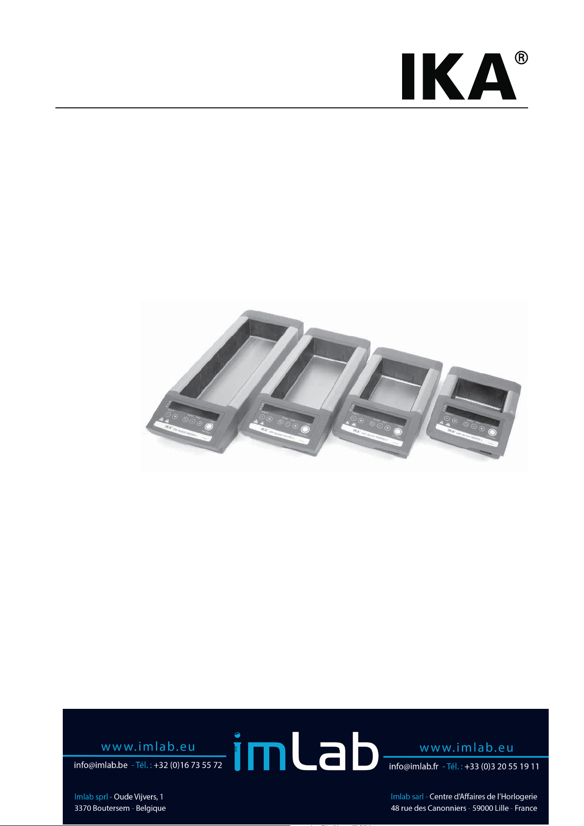
IKA® Dry Block Heater 1
IKA
IKA
IKA
®
Dry Block Heater 2
®
Dry Block Heater 3
®
Dry Block Heater 4
Page 2
Source language: German
EN
Contents
Page
Declaration of conformity 10
Explication of warning symbols 10
Safety instructions 11
Unpacking 12
Correct use 12
Assembling the stand 12
Operation 13
Setting the operating mode 13
Controlling the temperature via contact thermometer 14
Maintenance and cleaning 14
Error codes 15
Technical data 16
Warranty 16
Declaration of conformity
We declare under our sole responsibility that this product corresponds to the directives 2014/35/EU, 2014/30/EU and 2011/65/EU
and conforms with the following standards or normative documents: EN 61010-1, EN 61010-2-010, EN 61326-1, EN 60529 and EN
ISO 12100.
Explication of warning symbols
General hazard
This symbol identifies information that is of vital importance for safeguarding your health
and safety. Disregarding this information can lead to health impairment and injuries.
DANGER
This symbol identifies information that is of importance for the technically correct func-
WARNING
CAUTION
tioning of the system. Disregarding this information can result in damage to the appliance or
to system components.
This symbol indicates information which is important for proper use of the appliance and/
or ensuring that the appliance functions correctly. Failure to observe this information can
lead to inaccurate results.
DANGER
Danger of being burnt! - Note on hazards arising from a hot surface.
10
Page 3
Safety instructions
General safety instructions
• Read the operating instructions in full before starting
up and follow the safety instructions.
• Keep the operating instructions in a place where they can be
accessed by everyone.
• Ensure that only trained staff work with the appliance.
• Follow the safety instructions, guidelines, occupational health
and safety and accident prevention regulations
• Socket must be earthed (protective ground contact).
• Before starting the device for the first time, ensure that the
connector cable is suitable for the type of socket used and that
a safe protective earth connection is assured.
DANGER
peratures in excess of 120 °C. Pay attention to the residual heat
after switching off.
unless it is cold!
Safety instructions - device arrangement
DANGER
• Set up the appliance in a spacious area on an even, stable,
clean, non-slip, dry and fireproof surface.
• The feet of the appliance must be clean and undamaged.
• The voltage stated on the type plate must correspond to the
mains voltage.
• The socket for the mains cord must be easily accessible.
• The power supply cable and cables to the external sensors must
not be allowed to come into contact with the hot mounting
plate.
• Check the appliance and accessories beforehand for damage
each time you use them. Do not use damaged components.
Safety instructions - permissible media
WARNING
this device.
Risk of burns! Exercise caution when
touching the housing parts and the heating plate.
The device may not be transported
Do not operate the appliance in explosive atmospheres, with hazardous substances or under water.
Caution! Only media whose flashpoint
lies above the safety temperature limit of
130 °C may be processed or heated with
The heating plate can reach tem-
Safety instructions - performance of trials
WARNING
there is a risk from:
- splashing and evaporation of liquids
- ejection of parts
- release of toxic or combustable gases.
• Immerse external temperature sensors (PT 1000 ...) at least 20
mm deep into the medium or insert the sensor into the hole
provided for the purpose in the temperature control block.
• The PT 1000 external temperature sensor must always be inserted in the block / media when connected.
• Do not heat liquid media except with the block. Never pour
liquid media directly on to the heating plate!
• Safe operation is only guaranteed with the accessories described in the ”Accessories” chapter.
• Always disconnect the plug before fitting accessories.
• Accessories must be securely attached to the device and cannot come off by themselves. The centre of gravity of the assembly must lie within the surface on which it is set up.
• Refer to the operating instructions for the accessories.
Safety instructions - power supply/ switching off the device
WARNING
• The device will automatically restart in mode B following any
interruption to the power supply.
For protection of the equipment
• The appliance may only be opened by experts.
• Do not cover the device, even partially e.g. with metallic plates
or film. This results in overheating.
• Ensure that the base plate is kept clean.
• Protect the appliance and accessories from bumps and impacts.
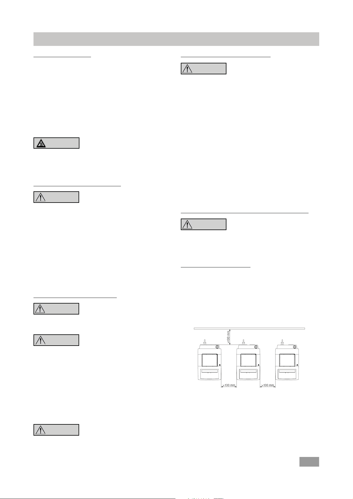
• Observe the minimum distances between the devices, between the device and the wall and above the assembly (min.
800 mm), see Fig. 2.
Wear your personal protective equipment
in accordance with the hazard category
of the media to be processed. Otherwise
The appliance can only be disconnected
from the mains supply by pulling out the
mains plug or the connector plug.
WARNING
- flammable materials
- combustible media with a low boiling temperature
- glass breakage
- incorrect container size
- overfilling of media (in a beaker)
- unsafe condition of container.
• Process pathogenic materials only in closed vessels under a
suitable extractor hood. Please contact IKA
questions.
DANGER
extra energy produced in other ways, e.g. through light irradiation.
• Bear in mind the possibility of contamination that might lead
to undesirable chemical reactions.
Beware of hazards due to:
®
if you have any
Only process media that will not react
dangerously to the extra energy produced
through processing. This also applies to any
Fig. 2
11
Page 4

Unpacking
• Unpacking
- Please unpack the device carefully
- In the case of any damage a fact report must be sent immediately (post, rail or forwarder)
Correct use
• Use
- For heating media in block heaters
• Range of use (interior areas only)
- Laboratories - Schools
- Pharmacies - Universities
Assembling the stand
) Remove the protective cap from the support rod.
) Put the washer between housing and nut.
) Screw the support rod onto the device by hand until the end
stop is reached.
• Delivery scope
®
Dry Block Heater,
- IKA
Depending on the IKA® Dry Block Heater model 1.2, 3, or 4
- Mains cable
- Temperature sensor PT 1000.60
- Operating instructions
The safety of the user cannot be guaranteed if the appliance is
operated with accessories that are not supplied or recommended
by the manufacturer or if the appliance is operated improperly
contrary to the manufacturer’s specifications or if the appliance
or the printed circuit board are modified by third parties.
) Using an open-jaw spanner 17 AF gently tighten the nut
(tightening torque max. 0.5 Nm).
) Accessories should be attached using cross sleeves.
Fig. 3
12
Page 5

Operation
Commissioning) Move device switch (E) to the OFF position
IKA® Dry Block Heater 1 IKA® Dry Block Heater 2 IKA® Dry Block Heater 3 IKA® Dry Block Heater 4
) Insert the mains power cable into the power socket (A)
) Move device switch (E) to the ON position
Ö The unit will be set to factory setting mode A (see “Operating modes”)
Heating
Ö The value selected will be shown on the display (L)
) Set the target temperature using the heater buttons +/- (J) and (K)
) Start the heating function by pressing the "Start / Stop" button (F)
i Ö When the heating is on, the LED (O) lights up.
i Ö During standby operation, the display (L) will show HOt if the base plate tempe ature is above 50 °C
Connecting
external
thermometers
direct temperature PT 1000.60 temperature sensor to the socket (B)
(
control in the media)) Move device switch (E) to the ON position
i Temperature sensor PT 1000
Ö The actual temperature for the temperature sensor shown on
display (L) will correspond to the temperature of the media.
The LED "external temperature sensor"” PT 1000 (N) will be lit.
) Move device switch (E) to the OFF position
) Detach contact plug (D)
) Attach a DIN 12878 (Class 2) compliant safety contact thermometer or a
The set-point and actual temperatures will be shown alternately on the display ((L) is blinking):
Setting operating mode
Operating the device in mode A or B
Mode A
All settings will be stored if the device is switched off or disconnected from the power supply. The heating functions will be set
to OFF when the device is powered on.
Mode B
All settings will be stored if the device is switched off or disconnected from the power supply. The heating function will be set
to ON or OFF when the device is powered on, depending on the
previous status of the device..
Factory setting: mode A
The mode selected will be shown on the display when the
device is started up.
A
Mode
Change the mode
) Move device switch (E) to the OFF position
) Keep the selection button (F) depressed
) Move device switch (E) to the ON position
) Release the selection button (F)
i Ö The set mode is indicated on the
Display (P) b
13
Page 6

Timer/Counter
After the device has been switched on, the "Timer/ Counter" button (I) can be used to toggle between timer mode and counter
mode.
Timer
Pressing the buttons "+" (G) and "-" (H) allows selection of a
time period of up to 99 hours and 59 minutes. Once the heating
function (F) is activated, the preset time starts to run. When the
total time has run down to 00 hours and 00 minutes, a warning
buzzer sounds for 30 seconds and in addition the display flashes.
The heating function is then deactivated.
Controlling the temperature via contact thermometer
Counter
When the heating function is stated by pressing the button (F)
the counter is activated. In counter mode the time is counted
upwards from 00 hours 00 minutes until the heating function is
stopped. The counter always starts from 00:00 hh:mm.
Selection of Timer/Counter
Pressing the button (I) toggles between timer mode and counter
mode. The mode can be activated only when the heating function is off.
The preferable method for controlling the average temperature
is with the contact thermometer. After the set point temperature has been adjusted, this results in a short heating-up time,
practically no temperature drift and only minor fluctuation in
temperature.
A 6-pin jack is located on the rear side of the instrument for
connecting the contact thermometer or the contact plug. The
electronics of the instruments returns a test current that must
flow via connector pins 3 and 5 for the heating plate to heat up.
Settings
For the detailed instructions for settings and limit values, refer to
the operating instructions for the instrument you are connecting.
The target temperature of the medium is set at the contact
thermometer. The heater buttons +/- (J) and (K) on the de-
vice can be used to preselect the required surface temperature of the heating plate.
Maintenance and cleaning
The device is maintenance-free.
Cleaning
For cleaning disconnect the main
plug.
Only use cleansing agents which have been recommended by
®
.
IKA
Dyes Isopropyl alcohol
Construction materials Water containing surfactant,
isopropyl alcohol,
Cosmetics Water containing surfactant,
isopropyl alcohol
Foodstuffs Water containing surfactant
Fuels Water containing surfactant
- Do not allow moisture to get into the appliance when cleaning.
- Wear protective gloves when cleaning the devices.
- Please consult with IKA
mination methods, other than those recommended here.
®
before using any cleaning or deconta-
Safety contact thermometers
acc. to DIN 12 878 class 2 or acc. Gerstel are connected with
a three-wire cable, the test current flows through the contact
thermometer.
Safety function
If the test current is interrupted because of e.g. breakage of
contact thermometer or falling out of the cable plug, the heating cuts off. The required plug allocation is indicated on a reference plate above the diode bushing.
Contact thermometer without safety circuit
acc. to DIN 12 878 class 0. The instrument only heats if the test
current circuit is closed by an electrical connection of the plug
pins 3 and 5.
Ordering spare parts
When ordering spare parts, please give:
- Machine type
- Manufacturing number, see type plate
- Item number and designation of the spare part, see
www.ika.com
- Software version
Repair
In case of repair the device has to be cleaned and free from any
materials which may constitute a health hazard. Please request
the form to "clearance certificate" from IKA. Or, use the download-print the form to the IKA
If you require servicing, return the appliance in its original
packaging. Storage packaging is not sucient. Please also use
suitable transport packaging.
®
website www.ika.com.
14
Page 7

Error codes
Any malfunctions during operation will be identified by an error message on the display (LED (P)).
Proceed as follows in such cases:
) Switch off device using the main switch (E)
) Carry out corrective measures
) Restart device
Error code Cause Effect Solution
E 3 Temperature inside device too high Heating off Switch off device and allow to cool down
E 6 Break in safety circuit Heating off - Plug in contact plug (D)
- Plug in PT 1000 contact thermometer /
temperature sensor
- Replace faulty connecting cable, plug, or
contact thermometer
E 25 Heating and switching element monitoring Heating off - Switch off device
- Warning! Only to be carried out by autho rised service personnel: Carry out an internal
test on the device to check the plug-in
connector for the heating element
E 26 Difference between temperature of safety Heating off - Switch off device
sensor and temperature of control sensor - Warning! Only to be carried out by autho control temperature > (safety temperature rised service personnel: Carry out an internal
+ 40 K)) test on the device to check the temperature
sensor
If the actions described fail to resolve the fault or another error code is displayed then take one of the following steps:
- contact the IKA
- send the device for repair, including a short description of the fault.
®
service department,
15
Page 8

Technical Data
IKA® IKA® IKA® IKA
Dry Block Dry Block Dry Block Dry Block
Heater 1 Heater 2 Heater 3 Heater 4
Operating voltage range Vac 220 - 230 ± 10%
Vac 115 ± 10%
Vac 100 ± 10%
Rated voltage Vac 230/ 50 Hz
Vac 115/ 60 Hz
Vac 100/ 60 Hz
Frequence Hz 50 / 60
Display digital
Temperature range °C ambient temperature +5 - 120
Timer min/h 1 min to 99 h 59 min
Perm. duration of operation % 100
Perm. ambient temperature °C +5 to +40
Perm. humidity % 80
Protection acc. to DIN EN 60529 IP 21
Protection class I
Overvoltage category II
Contamination level 2
Operation at a terrestrial altitude m max. 2000 about sea level
Dimension (W x D x H) mm 151 x 228 x 73 151 x 304 x 73 151 x 380 x 73 151 x 456 x 73
W
eight kg 1 1.3 1.7 2
Heating
Power consumption (+10%) max. at 230 Vac W 165 250 330 412
115 V
ac 165 250 330 412
ac 165 250 330 412
100 V
Temperature sensor PT 1000 variation K
DIN EN 60751 Kl. A
Temperature stability within the blocks at 37 ºC
Temperature stability within the blocks at 60 ºC
Temperature homogenity within the the blocks at 37 ºC
Temperature homogenity within the the blocks at 60 ºC
Heating rate (PT 1000 in solid block)
Fixed safety cir
Safety temperature limit °C 150
cuit
°C + 0.2 + 0.2 + 0.2 + 0.2
°C + 0.4 + 0.4 + 0.4 + 0.4
K + 0.2 + 0.2 + 0.3 + 0.3
K + 0.4 + 0.4 + 0.6 + 0.6
K/min 5.0 4.5 4.0 4.0
< + 0.1*
®
* Test parameter: with test block and glass vessel filled with M50 oil
Subject to technical changes!
Warranty
In accordance with IKA® warranty conditions, the warranty period is 24 months. For claims under the warranty please contact
your local dealer. You may also send the machine direct to our
factory, enclosing the delivery invoice and giving reasons for the
claim. You will be liable for freight costs.
The warranty does not cover worn out parts, nor does it apply
to faults resulting from improper use, insucient care or maintenance not carried out in accordance with the instructions in this
operating manual.
16
 Loading...