

IKA C-MAG HS4, C-MAG HS7, C-MAG HS10, C-MAG HP4, C-MAG HP7 Operating Instructions Manual
...Page 1
CMAG_012016
20000005327
O EN
B DE
M ’ FR
I PT
I ES
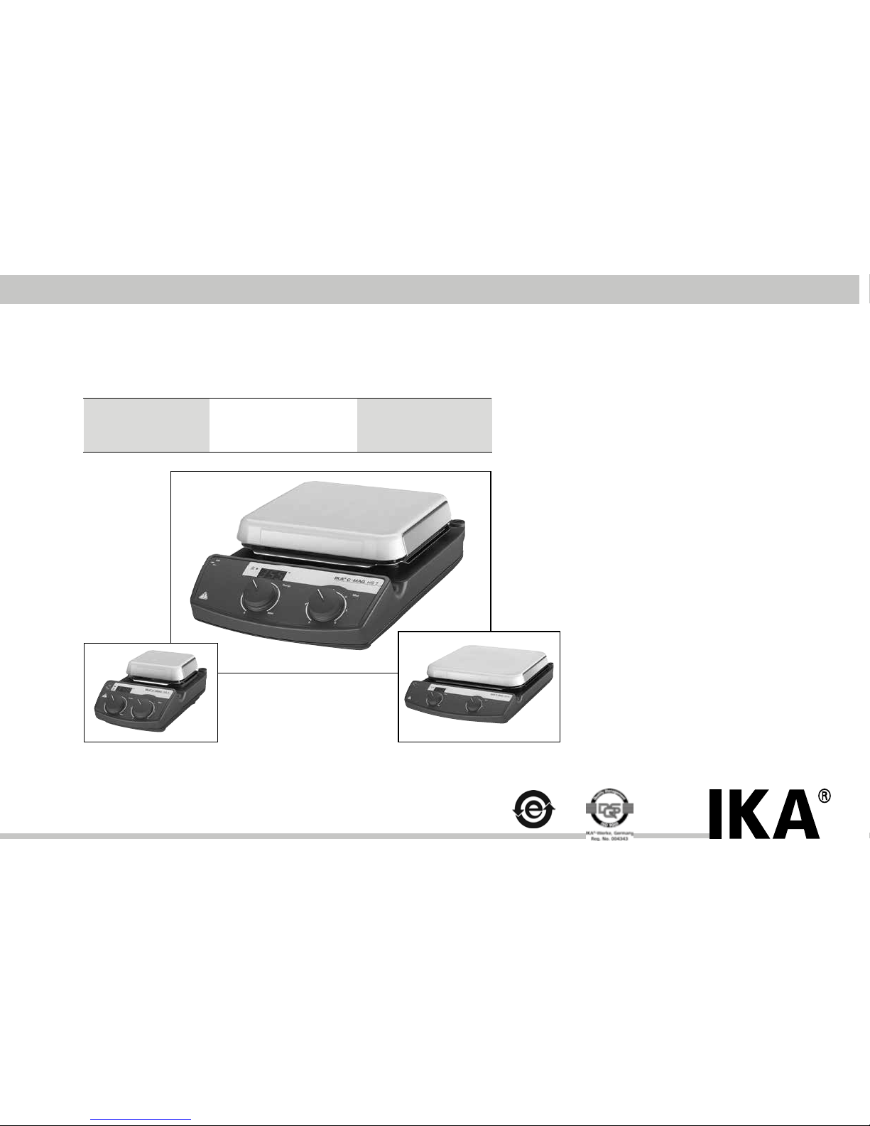
C-MAG HS4 C-MAG HS7 C-MAG HS10
C-MAG HP4 C-MAG HP7 C-MAG HP10
C-MAG MS4 C-MAG MS7 C-MAG MS10
C-MAG HS 4
C-MAG HS 7
C-MAG HS 10
IKA® WERKE
Page 2
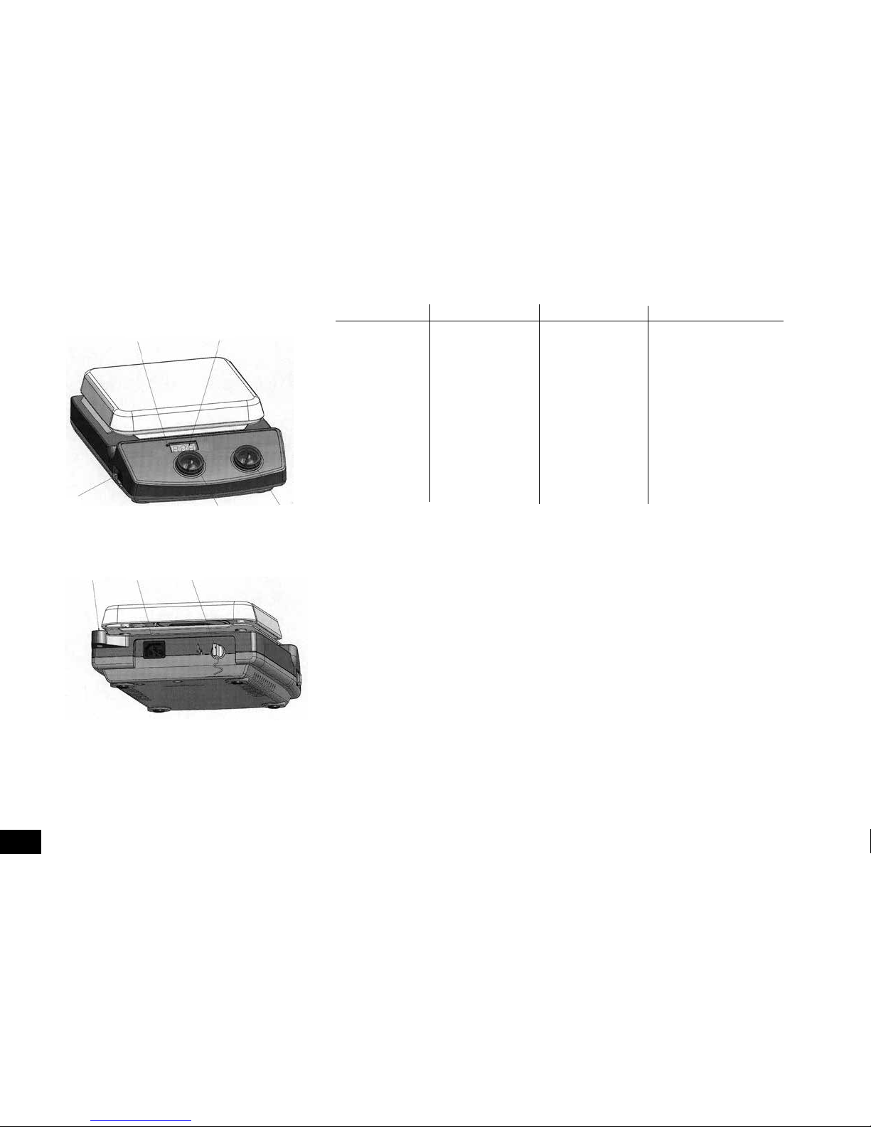
Item Designation Pos. Bezeichnung Pos. Désignation
Pos. Descriçao
A Switch A Geräteschalter A Commutateur
A Switches Dispositivos
B LED heating B LED B DEL B LED
C Display C Display C Affichage C Display
D Rotary knob D Bedienknopf D Bouton rotatif D
Botão de regulação
motor Motor moteur motor
E Rotary knob E Bedienknopf E Bouton rotatif E
Botão de regulação
heater Heizung chauffage
aquecimento
F Threaded F Stativgewin- F Alésage fileté
F Buraco do tripé
support bore debohrung du statif
com rosca
G Mains socket G Netzbuchse G Prise secteur G
Power jack
H Contact- H Kontakt- H douille de H Contato termômetro
thermometer- thermometer- thermomêtre bucha
jack Buchse de contact
2
Fig. 1
B
C
A
D
E
F
G
H
KONFORMITÄTSERKLÄRUNG DE
Wir erklären in alleiniger Verantwortung, dass dieses Produkt den Bestimmungen der Richtlinien 2011/65/EU, 2014/30/EU und
2014/35/EU entspricht und mit den folgenden Normen und norminativen Dokumenten übereinstimmt:
EN 61010-1, EN 61010-2-010, EN 61010-2-051, EN 60529, EN 61326-1 und EN ISO 12100.
DECLARATION OF CONFORMITY EN
We declare under our sole responsibility that this product corrosponds to the regulations 2011/65/EU, 2014/30/EU and
2014/35/EU and conforms with the standards or standardized documents EN 61010-1,
EN 61010-2-010,
EN 61010-2-051,
EN 60529, EN 61326-1 and EN ISO 12100.
DÉCLARATION DE CONFORMITÉ FR
Nous déclarons sous notre propre responsabilité que se produit est conforme aux réglementations 2011/65/UE, 2014/30/UE et
2014/35/UE et en conformité avec les normes ou documents normalisés suivant EN 61010-1,
EN 61010-2-010,
EN 61010-2-051,
EN 60529, EN 61326-1 et EN ISO 12100.
DECLARAÇÃO DE CONFORMIDADE PT
Declaramos, sob responsabilidade exclusiva, que este produto cumpre as disposições das diretivas 2011/65/EU e 2014/30/
EU e 2014/35/EU
e está de acordo com as seguintes normas ou documentos normativos EN 61010-1 e
EN 61010-2-010 e
EN
61010-2-051 e EN 60529 e EN 61326-1 e EN ISO 12100.
Page 3
3
Page
Declaration of conformity 2
Safety instructions 3
Unpack 4
Correct use 4
Commissioning 5
Error codes 6
Accessories 6
Maintenance 6
Warranty 7
Technical data 8
List of spare parts 9
Spare parts diagram 34/35
To your protection
Read the operating instructions in full before starting up
and follow the safety instructions.
• Keep the operating instructions in a place where they can be
accessed by everyone.
• Ensure that only trained staff work with the appliance.
• Follow the safety instructions, guidelines, occupational health
and safety and accident prevention regulations.
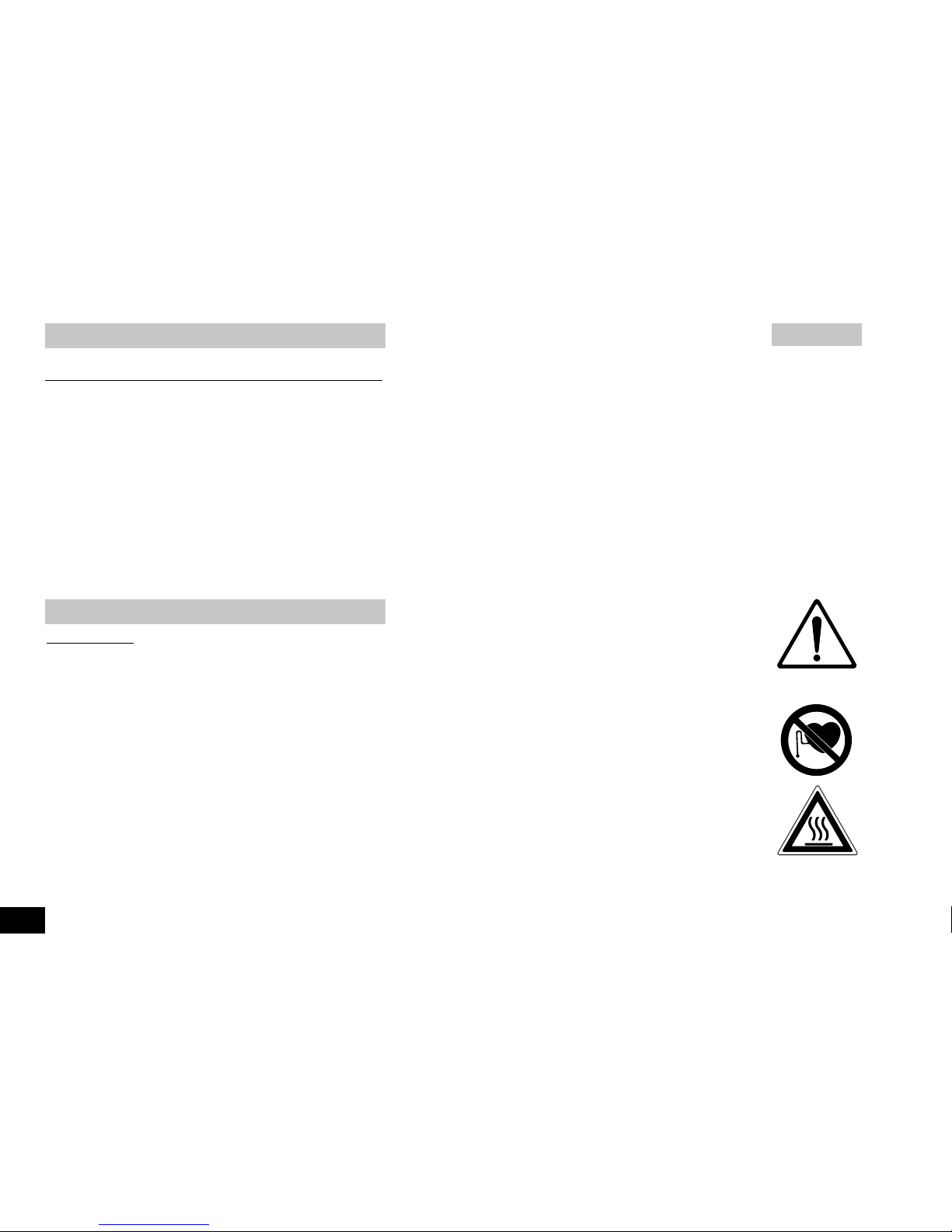
• Socket must be earthed (protective ground contact).
• Attention - Magnetism! Effects of the magnetic field have
to be taken into account (e.g. data cardiatic, carriers pacema kers...).
•
Risk of burns! The heating plate can reach temperatures in
excess of 500 °C. Pay attention the residual heat after swit ching off..
Please make sure that the mains cable does not contact the
heating plate
• Wear your personal protective equipment in accordance with the
hazard category of the medium to be processed. Otherwise
there is a risk of:
- splashing liquids
- projectile parts
- release any toxic or combustable gases.
• Set up the appliance in a spacious area on an even, stable, clean,
non-slip, dry and fireproof surface.
• The feet of the appliance must be clean and undamaged.
• Position the knob at the left stop before starting up. Gradually
increase the speed.
• Reduce the speed if
- the medium splashes out of the vessel because the speed is
too high
- the appliance is not running smoothly
-
the container moves on the set-up surface.
• Caution! Only process and heat up any media that has a flash
point higher than the adjusted target temperature (0 to 550 °C)
that has been set.
The target temperature must always be set to at least 25 °C
lower than the fire point of the media used.
•
When using PTFE-coated magnetic bars, the following hase
to be noted:
Chemical reactions of PTFE occur in contact with
molten or dissolved alkaline and alkaline - earth metals, as well
as with fine-particled powders of metals of the 2. and 3. group
of the periodical system at temperatures above 300-400°C.
Only elementary fluorine, chlorine trifluoride und alkaline metals
do attack PTFE, halogen hydrocarbons have a reversibly swelling
effect.
Source: Römpps Chemie-Lexikon and „Ullmann“ Bd.19
• Check the appliance and accessories beforehand for damage
each time you use them. Do not use damaged components.
• Only replace damaged parts with spare parts identical to the ori
ginal in function and quality.
• Do not use the device if the ceramic set-up surface is damaged
e.g. scratches, splinters or corrosion. A damaged set-up surface
could break if used.
• Beware of the risk of
Contents
Safety instructions
Page 4
- flammable materials
- glass breakage as a result of mechanical shaking power
- incorrect container size
- too much medium
- unsafe condition of container
• Only process media that will not react dangerously to the extra
energy produced through processing. This also applies to any
extra energy produced in other ways, e.g. through light irradiation.
• Do not operate the appliance in explosive atmospheres, with
hazardous substances or under water.
• A seperation from the line is made with the equipment only by
pulling net and/or device plug.
• Safe operation is only guaranteed with the accessories described
in the ”Accessories” chapter.
• Always disconnect the plug before fitting accessories.
• Accessories must be securely attached to the device and cannot
come off by themselves. The centre of gravity of the assembly
must lie within the the set-up surface.
• The appliance starts up again automatically following a cut in the
power supply.
• The appliance may heat up when in use.
• Abrasion of the dispersion equipment or the rotating accessories
can get into the medium you are working on.
To the protection of the equipment
• The voltage stated on the nameplate must correspond to the
mains voltage.
• Do not cover the device, even partially e.g. with metallic plates
or film. This results in overheating.
• Protect the appliance and accessories from bumps and impacts.
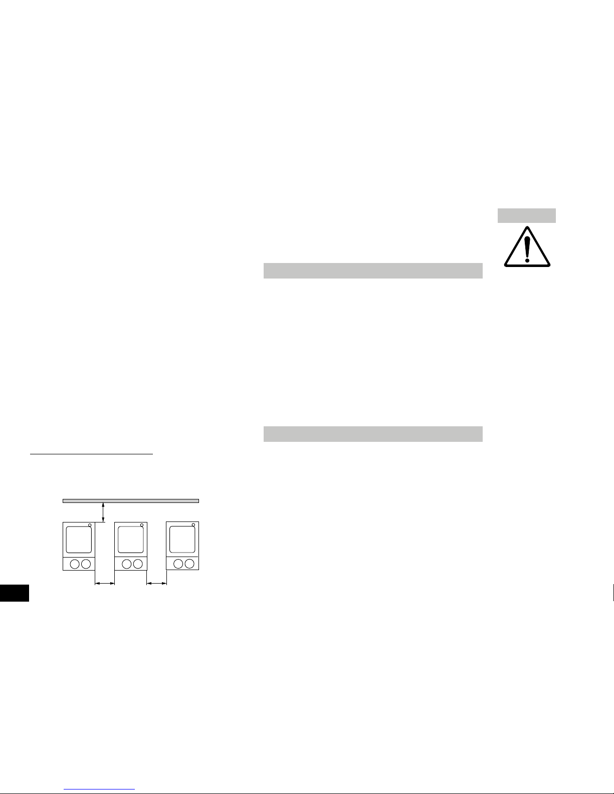
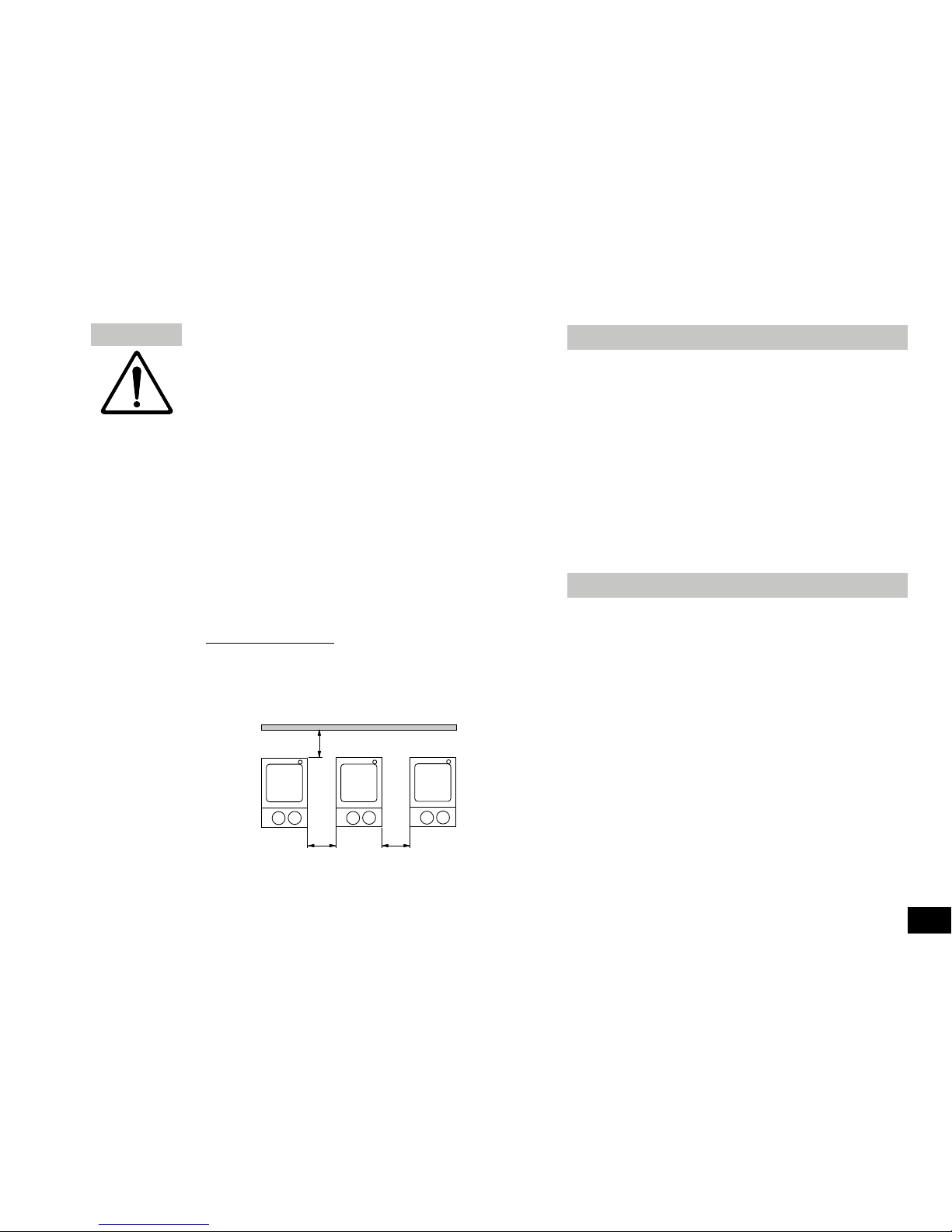
• Observe the minimum distances between devices, between the
device and the wall as given in the Fig. 2 and above the assem bly (min. 800mm)
4
> 100 mm > 100 mm
> 100 mm
•
Unpack
- Please unpack the device carefully
- In the case of any damage a fact report must be sent
immediately (post, rail or forwarder)
•
Delivery scope
- Heating magnetic stirrer or
Magnetic stirrer or
Heating device
- Mains cable
- Operating instructions
•
Use
-
For mixing and/or heating liquids
•
Range of use
- Laboratories - Schools
- Chemical industry - Pharmacies
Unpack
Correct use
Fig. 2
Page 5
5
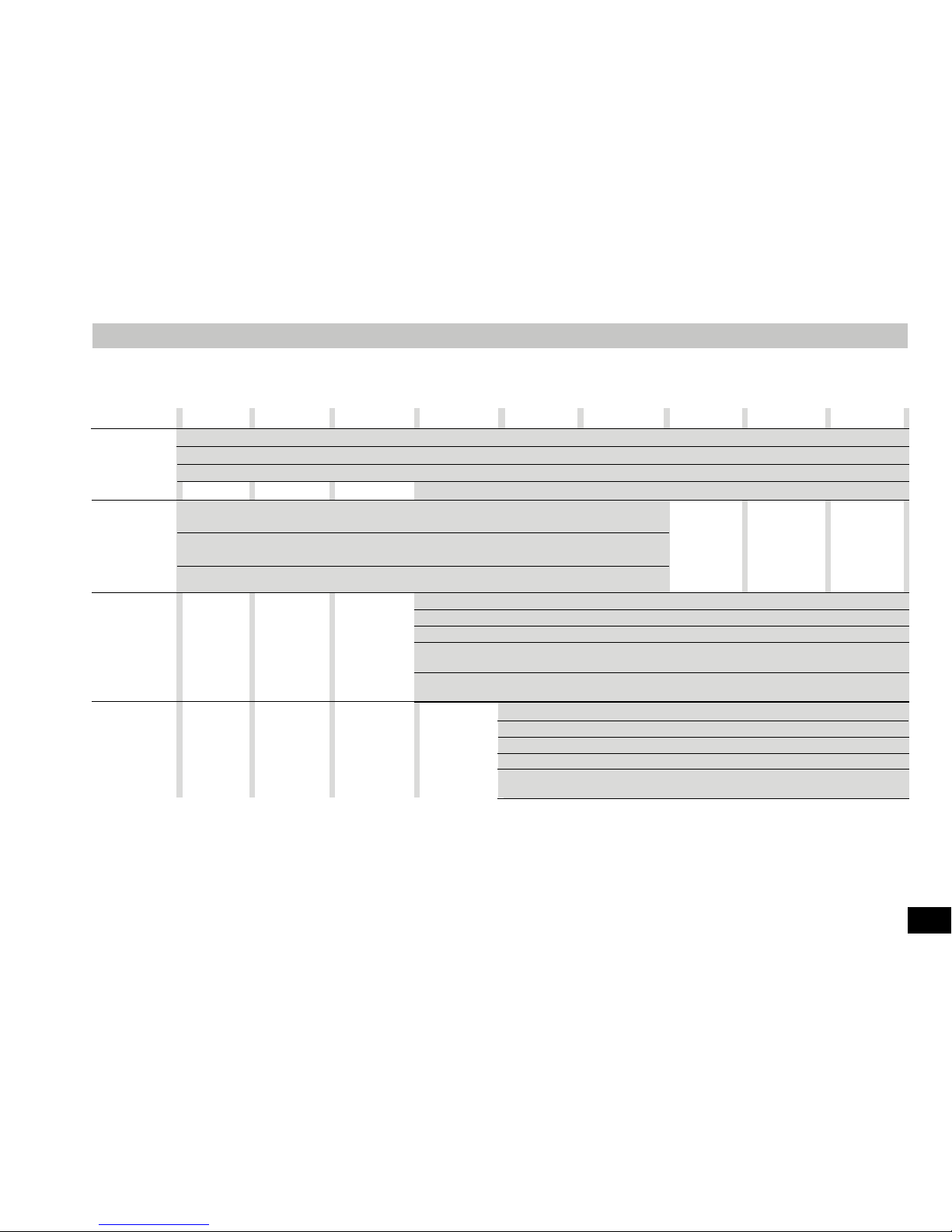
Commissioning
Stirring
Heating
Contactthermometer
connection
MS 4 MS 7 MS 10 HS 4 HS 7 HS 10 HP 4 HP 7 HP 10
Put device switch (A) in the OFF position
Plug in (G) mains cable
Once connected to the power supply the device is in “stand-by” mode
The right decimal point on the display (C) is lit
Commissioning
Put device switch (A) in the ON position
Any set values are retained when device is switched off and even after the device is
disconnected from the power!
Set the engine speed with the operating button (E) on the right
Put device switch (A) in the ON position
Any set values are retained when device is switched off and even after the device is disconnected from the power!
Set the target temperature for the heating plate using operating button (D) [for VHP (E)]
The set value is indicated on the display (C). If energy is being supplied to the heating plate,
the red LED (B) lights up
In the stir and stand-by modes, “hot” flashes on the display after the heat has been switched off
for as long as the temperature of the set-up surface exceeds 50°C
Put device switch (A) in the OFF position, unplug contact plug
Safety contact thermometer acc. to DIN 12878 class 2 connected with jack (H)
Put device switch (A) in the ON position
Beware the instruction manual of the contact thermometer
Important: Display (C) also indicates the target temperature of the heating plate when the cont
-
act thermometer is connected
Page 6
6
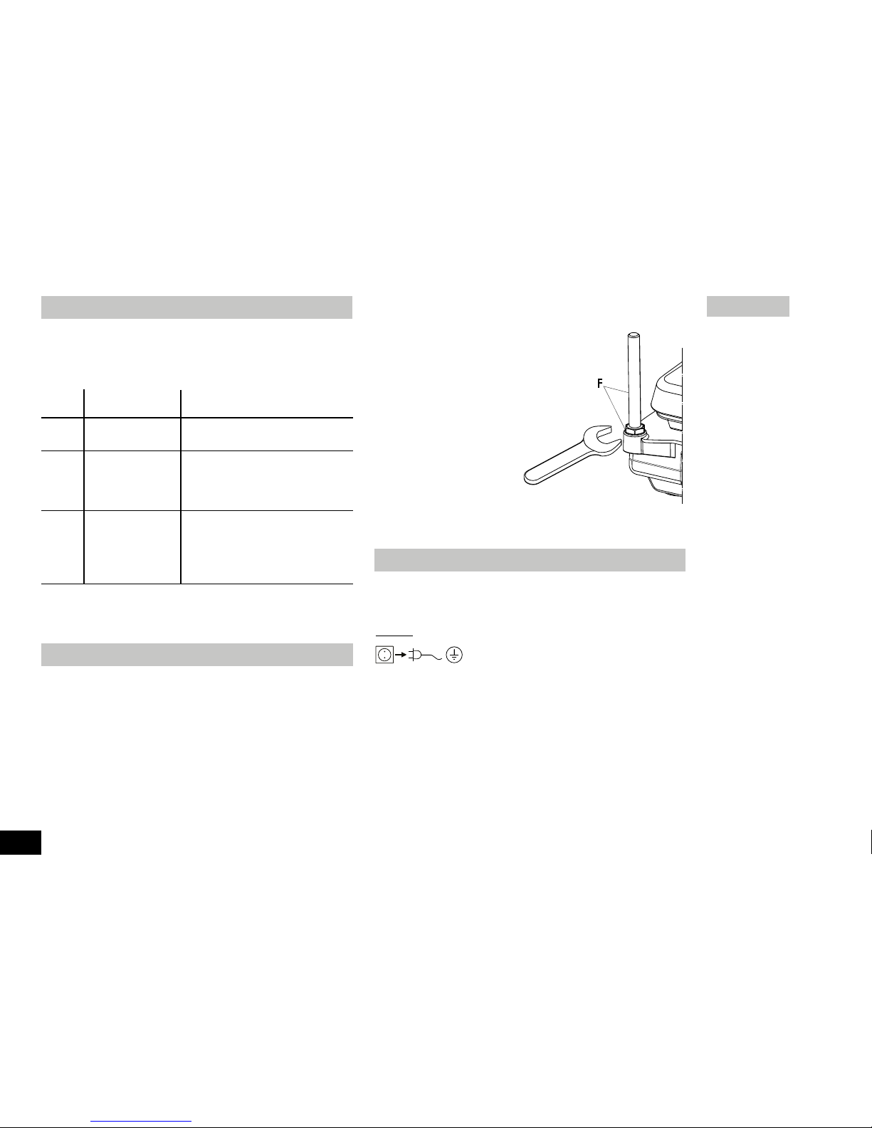
Installing the support rod
The support rod is attached using the thraeded support bore (F).
• Screw nut M10 on to the support rod as far
as the stop
• Screw on the support rod as far as the
stop by hand
• Tighten the support rod and nut M10
using a flat wrench (SW17).
•
Use bossheads to assemble
accessory parts or acces sory devices.
The appliance is maintenance-free.
Cleaning
Only use cleansing agents which have been recommended by
IKA®.
Use to remove:
Dyes isopropyl alcohol
Construction materials water containing tenside/
isopropyl alcohol
Cosmetics water containing tenside/
isopropyl alcohol
Foodstuffs water containing tenside
Fuels water containing tenside
- Do not allow moisture to get into the appliance when cleaning
- Wear protective gloves during cleaning the devices.
F
17
Footstep during the enterprise a disturbance up, is indicated these
with the devices to HS and HP by an error message in the display (C).
Whenever an error message appears switch the device off to cool down.
Error codes
Error Cause Solution
code
E1 Inner temperature • switch off the unit and allow it
too high cool down
E6 Motor seized • Stirring bars inappropriate
• Reduce the viscosity
• Foreign bodies in the equipment
remove
E9 Safety circuit • Plug the contact plug (G)
ETC • Plug the contact thermometer
• Connecting cable, plug or
contact tthermometer defect,
exchange
Have the device repaired if the error is not corrected using the measures
described or if another error code is displayed.
Stirring organs
stirring bars: Ø 6 mm, lengts to 15mm
Ø 8 mm, lengts to 50mm
Ø10mm, lengt to 80mm
Any other accessories
RSE stirring bar remover
H36 holding rod
H16V support rod
H44 cross sleeve
ETS-D5 electrical contact thermometer
Accessories
Maintenance
Fig. 3
Page 7

- Before using another than the recommended method for clean ing or decontamination, the user must ascertain with IKA® that
this method does not destroy the instrument.
Spare parts order
When ordering spare parts, please give:
- Machine type
- Manufacturing number, see type plate
- Item and designation of the spare part,
see spare parts list and diagram
Repair
Please only send devices in for repair that have been cleaned
and are free of materials which might present health hazards.
For this, use the “certificate of compliance” form which you can
obtain from IKA
®
or can download a version for printing from the IKA®
website at www.ika.com.
If your appliance requires repair, return it in its original packaging.
Storage packaging is not sufficient when sending the device - also use
appropriate transport packaging.
In accordance with IKA® warranty conditions, the warranty period is
24 months. For claims under the warranty please contact your local
dealer. You may also send the machine direct to our works, enclosing
the delivery invoice and giving reasons for the claim. You will be liable
for freight costs.
The warranty does not cover wearing parts, nor does it apply to faults
resulting from improper use or insufficient care and maintenance contrary to the instructions in this operating manual.
7
Warranty
Page 8

8
230 ±10%
120 ±10%
100 ±10%
230 / 50Hz
120/ 60 Hz
100/ 60 Hz
50/60
30 270 255 30 1020 1005 30 1520 1505
30 270 255 30 1020 1005 30 1070 1055
2,5
100
+5 to +40
80
IP 21
I
II
2
max. 2000
150 x 260 x 105 220 x 335 x 105 300 x 415 x 105
3 5 6
100-1500 100-1500 - 100-1500 100-1500 - 100-1500 100-1500 Scale Scale - Scale Scale - Scale Scale -
15 15 - 15 15 - 15 15 1,5 1,5 - 1,5 1,5 - 1,5 1,5 5 5 - 10 10 - 15 15 -
100x100 100x100 100x100 180x180 180x180 180x180 260x260 260x260 260x260
- 250 250 - 1000 1000 - 1500 1500
- 250 250 - 1000 1000 - 1050 1050
- 50 50 - 50 50 - 50 50
- 500 500 - 500 500 - 500 500
- ±5 ±5 - ±5 ±5 - ±5 ±5
- 550 550 - 550 550 - 550 550
MS 4
HS 4
HP 4
MS 7
HS 7
HP 7
MS 10
HS 10
HP10
Operating voltage VAC
VAC
VAC
Nominal voltage VAC
VAC
VAC
Design frequence Hz
Input power max. at 230 and 120 VAC
W
100 VAC
Power consumption in stand-by mode W
Perm. duration of operation %
Perm. ambient temperature °C
Perm. relative humidity %
Protection type acc. to DIN EN 60529
Protection class
Overvoltage categorie
Contamination level
Operation at a terrestrial altitude m
Dimensions (W x D x H) mm
Weight kg
Motor
Speed range (infinitely) rpm
Speed display
Power input W
Power output W
Max. stirring quantity (water) ltr
Heating plate
Heating plate dimension mm
Heating power at 230 and 120 VAC W
at 100 VAC
Surface temperature min. C°
Surface temperature max. C°
Temperature fluctuation* C°
Limit of safety temperaure C°
Technical data
* On a certain point, without vessel, heating plate centre at 100 °C.
Page 9
9
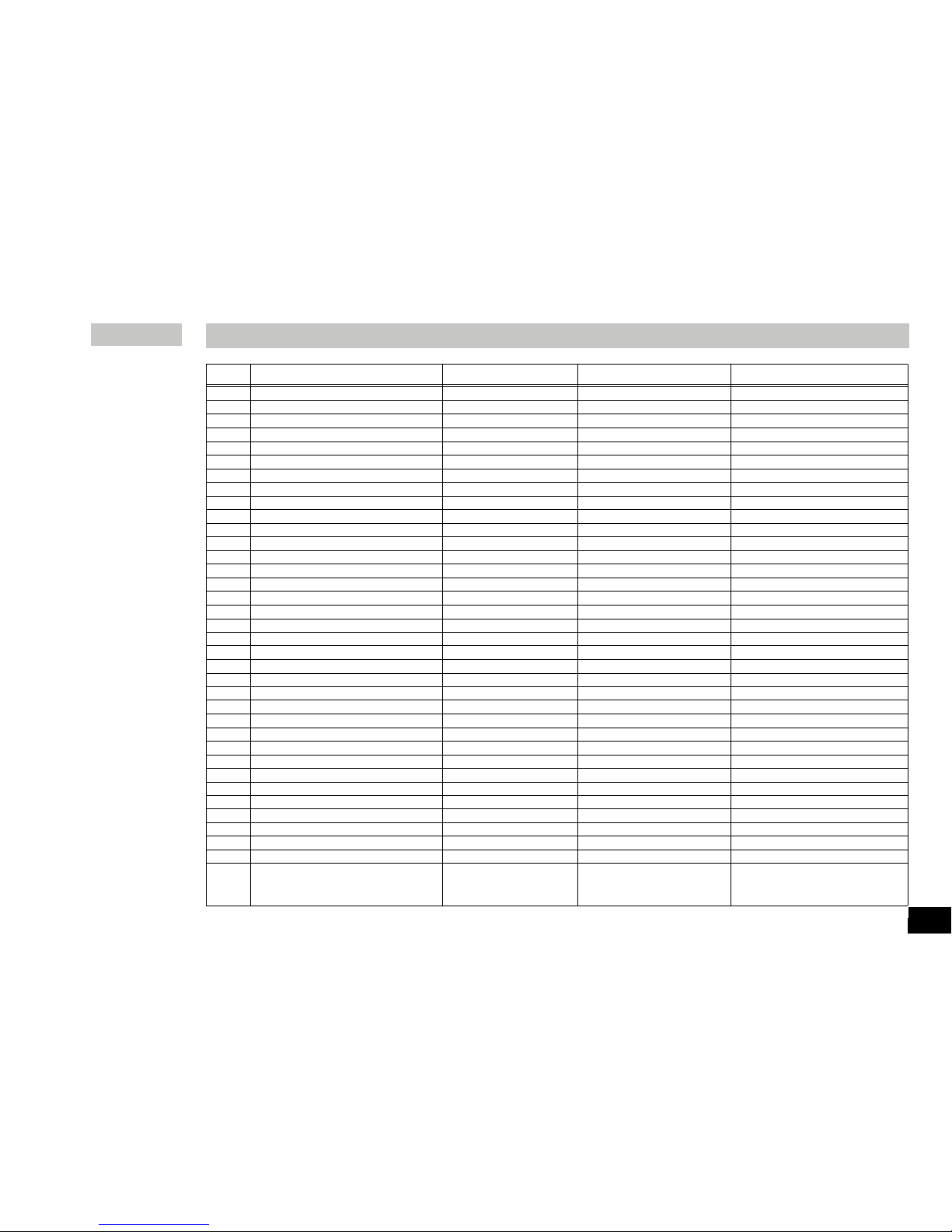
Pos. Designation MS-C4/C7/C10 HP-C4/C7/C10 HS-C4/C7/C10
7 Contersunk srew X X X
8 Connect distributer X X X
12 Insulating X X
13 Danger sign X X
17 Distance hoderLP X X X
18 Clip-Triac fastening X X X
19 Angel connector X X X
20 Cover X X X
21 Mounting plug X X X
31 Placing plate X X X
32 Heating foil X X
33 Insulating X X
35 Ceramic bushing X X
37 Holding bracket X X X
38 Protectione sheet X X X
40 Distance bushing X X X
41 Distance bushing X X X
45 Mylar-foil X X X
46 Color filter foil X X
47 Front foil X X X
51 Control knob X X X
53 Contact plug X X
54 Magnet X X
59 Shaded pole asynchron motor X X
65 Device pedestal X X X
66 Impulse disk X X
70 Distance bushing X X
71 Magnett holder X X
75 Temperature sensor X X
76 Pressure sheet X X X
80 Contact thermometer bushing X X
80 Cap (Contact-thermometer) X
81 Connecting cable X X X
100 Label X X X
2001 PCB compl. X X X
2002 PCB accessories consisting of: X X X
Poti (motor); Poti (heating); Opto coupler and LED-display
List of spare parts
Page 10
10
Seite
Konformitätserklärung 2
Sicherheitshinweise 10
Auspacken 11
Bestimmungsgemäßer Gebrauch 11
Bedienung 12
Fehlercodes 13
Zubehör 13
Instandhaltung 13
Gewährleistung 14
Technische Daten 15
Ersatzteilliste 16
Ersatzteilbild 34/35
Zu Ihrem Schutz
Lesen Sie die Betriebsanleitung vor Inbetriebnahme voll ständig und beachten Sie die Sicherheitshinweise.
• Bewahren Sie die Betriebsanleitung für Alle zugänglich auf.
•
Beachten Sie, dass nur geschultes Personal mit dem Gerät arbeitet.
•
Beachten Sie die Sicherheitshinweise, Richtlinien, Arbeitsschutzund Unfallverhütungsvorschriften.
• Steckdose muss geerdet sein (Schutzleiterkontakt).
• Achtung - Magnetismus! Beachten Sie die Auswirkungen
des Magnetfeldes (Herzschrittmacher, Datenträger...).
•
Verbrennungsgefahr! Die Heizplatte kann über 500 °C
heiß werden. Restwärme nach dem Ausschalten beachten.
Stellen Sie sicher, dass das Netzkabel die Heizplatte nicht
berührt!
• Tragen Sie Ihre persönliche Schutzausrüstung entsprechend der
Gefahrenklasse des zu bearbeitenden Mediums. Ansonsten be steht eine Gefährdung durch:
- Spritzen und Verdampfen von Flüssigkeiten
- Herausschleudern von Teilen
- Freiwerden von toxischen oder brennbaren Gasen
• Stellen Sie das Gerät frei auf einer ebenen, stabilen, sauberen,
rutschfesten, trockenen und feuerfesten Fläche auf.
• Die Gerätefüße müssen sauber und unbeschädigt sein.
• Stellen Sie vor Inbetriebnahme die Drehknöpfe auf Linksan-
schlag. Steigern Sie die Drehzahl langsam.
• Reduzieren Sie die Drehzahl, falls
- Medium infolge zu hoher Drehzahl aus dem Gefäß spritzt
- unruhiger Lauf auftritt
- sich das Gefäß auf der Aufstellplatte bewegt.
• Achtung! Mit diesem Gerät dürfen nur Medien bearbeitet bzw.
erhitzt werden, deren Flammpunkt über der eingestellten
Solltemperatur (0 ... 550 °C) liegt.
Die eingestellte Solltemperatur muss immmer mindestens 25 °C unterhalb des Brennpunktes des verwendeten Mediums liegen.
• Bei Verwendung von PTFE-ummantelten Magnetstäbchen ist
Folgendes zu beachten: Chemische Reaktionen von PTFE treten
ein im Kontakt mit geschmolzenen oder gelösten Alkali- und Erd alkalimetallen, sowie mit feinteiligen Pulvern von Metallen aus
der 2. und 3. Gruppe des Periodensystems bei Temperaturen
über 300-400 °C. Nur elementares Fluor, Chlortrifluorid und Al kalimetalle greifen es an,Halogenkohlenwasserstoffe wirken
reversibel quellend.
(Quelle: Römpps Chemie-Lexikon und „Ullmann“ Bd.19)
• Prüfen Sie vor jeder Verwendung Gerät und Zubehör auf Be schädigungen. Verwenden Sie keine beschädigten Teile.
• Ersetzen Sie beschädigte Teile nur durch Ersatzteile, die dem
Original in Funktion und Qualität gleich sind.
• Verwenden Sie das Gerät nicht, falls die keramische Aufstell platte Beschädigungen z.B. Kratzer, Absplitterungen oder Ver ätzungen aufweist. Eine beschädigte Aufstellplatte kann bei Be nutzung brechen.
• Beachten Sie eine Gefährdung durch
- entzündliche Materialien.
- Glasbruch
- falsche Dimensionierung des Gefäßes
- zu hohen Füllstand des Mediums
Inhaltsverzeichnis
Sicherheitshinweise
Page 11
- unsicheren Stand des Gefäßes
• Bearbeiten Sie nur Medien, bei denen der Energieeintrag durch
das Bearbeiten unbedenklich ist. Dies gilt auch für andere Ener gieeinträge, z.B. durch Lichteinstrahlung.
• Betreiben Sie das Gerät nicht in explosionsgefährdeten Atmos-
phären, mit Gefahrstoffen und unter Wasser.
• Trennung des Gerätes vom Stromnetz nur durch Ziehen des
Netzsteckers.
• Sicheres Arbeiten ist nur mit Zubehör, das im Kapitel „Zubehör“
beschrieben wird, gewährleistet.
• Montieren Sie Zubehör nur bei gezogenem Netzstecker.
• Zubehörteile müssen sicher mit dem Gerät verbunden sein und
dürfen sich nicht von alleine lösen. Der Schwerpunkt des Auf baus muss innerhalb der Aufstellfläche liegen.
• Nach einer Unterbrechung der Stromzufuhr läuft das Gerät von
selbst wieder an.
• Im Betrieb kann sich das Gerät erwärmen.
• Eventuell kann Abrieb vom Gerät oder von rotierenden
Zubehörteilen in das zu bearbeitende Medium gelangen.
Zum Schutz des Gerätes
• Spannungsangabe des Typenschildes muss mit Netzspannung
übereinstimmen.
• Decken Sie das Gerät nicht ab, auch nicht teilweise, z.B. mit
metallischen Platten oder Folien. Die Folge ist Überhitzung.
• Vermeiden Sie Stöße und Schläge auf Gerät oder Zubehör.
• Beachten Sie die Mindestabstände zwischen Geräten, zwischen
Gerät und Wand (wie in Fig. 2 dargestellt), sowie oberhalb des
Aufbaus (min. 800mm)
11
•
Auspacken
- Packen Sie das Gerät vorsichtig aus
- Nehmen Sie bei Beschädigungen sofort den Tatbestand auf
(Post, Bahn oder Spedition)
•
Lieferumfang
- Beheizbarer Magnetrührer oder
Magnetrührer oder
Heizgerät
- Netzkabel
- Betriebsanleitung
•
Verwendung
- zum Mischen und/oder Erhitzen von Flüssigkeiten
•
Verwendungsgebiet
- Laboratorien - Schulen
- Chemische Industrie - Apotheken
Auspacken
Bestimmungsgemäßer Gebrauch
> 100 mm > 100 mm
> 100 mm
Fig. 2
Page 12

12
Inbetriebnahme
Rühren
Heizen
Anschluss
Kontaktthermometer
MS 4 MS 7 MS 10 HS 4 HS 7 HS 10 HP 4 HP 7 HP 10
Geräteschalter (A) in OFF-Stellung bringen
Netzkabel (G) einstecken
Gerät befindet sich nach Anschließen an die Spannungsversorgung im “Stand-By”-Modus
Rechter Dezimalpunkt des Display (C) leuchtet
Inbetriebnahme
Geräteschalter (A) in ON-Stellung bringen
Eingestellte Werte bleiben nach Ausschalten und auch
nach Trennen des Gerätes vom Netzstrom erhalten!
Motordrehzahl mit dem
rechten Bedienknopf (E) einstellen
Geräteschalter (A) in ON-Stellung bringen
Eingestellte Werte bleiben nach Ausschalten und auch nach Trennen des Gerätes vom Netzstrom erhalten!
Mit dem Bedienknopf (D) [für VHP (E)] Solltemperatur der Heizplatte einstellen
Der eingestellte Wert wird auf dem Display (C) angezeigt. Wird der Heizplatte Energie zugeführt, leuchtet die rote
LED (B)
Im Rühr- und Stand-By-Betrieb wird nach Ausschalten der Heizung auf dem Display (C) blinkend “hot” angezeigt,
solange die Temperatur der Aufstellfläche 50°C überschreitet
Geräteschalter (A) in OFF-Stellung bringen Kontaktstecker abziehen
Sicherheitskontaktthermometer nach DIN 12878 Klasse 2 mit Buchse (H) verbinden
Geräteschalter (A) in ON-Stellung bringen
Bedienungsanweisungen des Kontaktthermometers beachten
Hinweis: Display (C) zeigt auch bei angeschlossenem Kontaktthermometer die Soll-Temperatur
der Heizplatte an
Page 13

13
Montage des Stativstabes
Die Befestigung des Stativstabes erfolgt über die Stativgewinde-bohrung
(F).
• Mutter M10 bis Anschlag auf Stativstab
schrauben
• Stativstab von Hand bis zum Anschlag
einschrauben
• Stativstange mit Mutter M10 mit einem
Gabelschlüssel (SW17) kontern.
•
Mittels Kreuzmuffen Zube hörteile oder Zubehör geräte montieren
Das Gerät arbeitet wartungsfrei.
Reinigung
Verwenden Sie nur von IKA® empfohlene Reinigungsmittel.
Verwenden Sie zum Reinigen von:
Farbstoffen Isopropanol
Baustoffen Tensidhaltiges Wasser, Isopropanol
Kosmetika Tensidhaltiges Wasser, Isopropanol
Nahrungsmitteln Tensidhaltiges Wasser
Brennstoffen Tensidhaltiges Wasser
- Beim Reinigen darf keine Feuchtigkeit in das Gerät dringen.
- Tragen Sie zum Reinigen des Gerätes Schutzhandschuhe.
F
17
Fehlercodes
Instandhaltung
Fig. 3
Tritt während des Betriebes eine Störung auf, wird diese bei den Geräten
HS und HP durch eine Fehlermeldung im Display (C) angezeigt. Schalten
Sie bei jeder Fehlermeldung grundsätzlich das Gerät zum Abkühlen aus.
Fehler Ursache Behebung
code
E1 Innentemperatur • Gerät ausschalten und abkühlen
zu hoch lassen
E6 Motor blockiert • Magnetstäbchen ungeeignet
• Viskosität verringern
• Fremdkörper im Gerät entfernen
E9 Sicherheits- • Kontaktstecker (G) einstecken
kreis ETC • Kontaktthermometer stecken
• Verbindungskabel, Stecker oder
Kontaktthermometer defekt,
austauschen
Geben Sie das Gerät in Reparatur, wenn sich der Fehler durch die
beschriebenen Maßnahmen nicht beseitigen lässt oder wenn ein anderer
Fehlercode angezeigt wird.
Rührorgane
Magnetstäbchen: Ø 6 mm, Länge bis 15mm
Ø 8 mm, Länge bis 50mm
Ø10mm, Länge 80mm
Sonstiges Zubehör
RSE Rührstäbchenentferner
H36 Haltestange
H16V Stativstab
H44 Kreuzmuffe
ETS-D5 elektronisches Kontaktthermometer
Zubehör
Page 14

- Falls andere als die empfohlenen Reinigungs- oder Dekonta minationsmethoden angewendet werden, fragen Sie bitte bei
IKA® nach.
Ersatzteilbestellung
Bei Ersatzteilbestellungen geben Sie bitte Folgendes an:
- Gerätetyp
- Fabrikationsnummer des Gerätes, siehe Typenschild
- Posição número e designação da peça de substituição, consulte
a lista de peças de reposição e peças de reposição de imagem.
Reparaturfall
Bitte senden Sie nur Geräte zur Reparatur ein, die gereinigt und
frei von gesundheitsgefährdenden Stoffen sind.
Fordern Sie hierzu das Formular „Unbedenklichkeitsbescheinigung“
bei IKA® an oder verwenden Sie den download Ausdruck
des Formulares auf der IKA® Website www.ika.com.
Senden Sie im Reparaturfall das Gerät in der Originalverpackung
zurück. Lagerverpackungen sind für den Rückversand nicht ausreichend.
Verwenden Sie zusätzlich eine geeignete Transportverpackung.
Entsprechend den IKA
®
-Verkaufs-und Lieferbedingungen beträgt die
Gewährleistungszeit 24 Monate. Im Gewährleistungsfall wenden Sie sich
bitte an Ihren Fachhändler, oder senden Sie das Gerät unter Beifügung
der Lieferrechnung und Nennung der Re-klamationsgründe direkt an
unser Werk. Frachtkosten gehen zu Ihren Lasten.
Die Gewährleistung erstreckt sich nicht auf Verschleißteile und gilt
nicht für Fehler, die auf unsachgemäße Handhabung und unzureichende Pflege und Wartung, entgegen den Anweisungen in dieser
Betriebsanleitung, zurückzuführen sind.
14
Gewährleistung
Page 15

230 ±10%
120 ±10%
100 ±10%
230 / 50Hz
120/ 60 Hz
100/ 60 Hz
50/60
30 270 255 30 1020 1005 30 1520 1505
30 270 255 30 1020 1005 30 1070 1055
2,5
100
+5 bis +40
80
IP 21
I
II
2
max. 2000
150 x 260 x 105 220 x 335 x 105 300 x 415 x 105
3 5 6
100-1500 100 - 1500 - 100-1500 100 - 1500 - 100-1500 100 - 1500 Skala Skala - Skala Skala - Skala Skala 15 15 - 15 15 - 15 15 1,5 1,5 - 1,5 1,5 - 1,5 1,5 5 5 - 10 10 - 15 15 -
100x100 100x100 100x100 180x180 180x180 180x180 260x260 260x260 260x260
- 250 250 - 1000 1000 - 1500 1500
- 250 250 - 1000 1000 - 1050 1050
- 50 50 - 50 50 - 50 50
- 500 500 - 500 500 - 500 500
- ±5 ±5 - ±5 ±5 - ±5 ±5
- 550 550 - 550 550 - 550 550
MS 4
HS 4
HP 4
MS 7
HS 7
HP 7
MS 10
HS 10
HP10
Betriebsspannung VAC
VAC
VAC
Nominalspannung VAC
VAC
VAC
Frequenz Hz
Leistungsaufnahme max. bei 230 und 120 VAC
W
100 VAC
Stromaufnahme im Standby-Betrieb W
Zulässige Einschaltdauer %
Zul. Umgebungstemperatur °C
Zul. relative Feuchte %
Schutzart nach DIN EN 60529
Schutzklasse
Überspannungskategorie
Verschmutzungsgrad
Geräteeinsatz über NN m
Abmessung (B x T x H) mm
Gewicht kg
Motor
Drehzahlbereich (stufenlos) rpm
Drehzahlanzeige
Aufnahmeleistung W
Abgabeleistung W
Max. Rührmenge (Wasser) ltr
Heizplatte
Heizplatten-/ Aufstellpattenabmessung mm
Heizleistung bei 230 und 120 VAC W
bei 100 VAC
Oberflächentemperatur min. C°
Oberflächentemperatur max. C°
Temperaturwelligkeit* C°
Sicherheitstemperaturbegrenzung
(fest eingestellt) C°
Technische Daten
15
* Auf einen bestimmten Punkt, ohne Gefäß, Heizplattenmitte bei 100 °C.
Page 16

16
Pos. Bezeichnung MS-C4/C7/C10 HP-C4/C7/C10 HS-C4/C7/C10
7
Senkschraube X X X
8 Steckverteiler X X X
12 Isolation X X
13 Warnschild X X
17 LP-Abstandshalter X X X
18 Clip-Triacbefestigung X X X
19 Winkelstecker X X X
20 Schutzhaube X X X
21 Einbaugerätestecker X X X
31 Aufstellplatte X X X
32 Folienheizung X X
33 Isolierung X X
35 Keramikbuchse X X
37 Halteklammer X X X
38 Strahlschutzblech X X X
40 Distanzhülse X X X
41 Distanzhülse X X X
45 Mylarfolie X X X
46 Farbfilterfolie X X
47 Frontfolie X X X
51 Bedienknopf X X X
53 Kontaktstecker X X
54 Magnet X X
59 Spaltpol-Asynchronmotor X X
65 Gerätefuß X X X
66 Impulsscheibe X X
70 Distanzbuchse X X
71 Magnetträger X X
75 Temperaturaufnehmer X X
76 Andruckblech X X X
80 Kontakt-Thermometer-Buchse X X
80 Abdeckung (Kontakt-Thermometer) X
81 Verbindungskabel X X X
100 Etikett X X X
2001 BLP kompl. X X X
2002 BLP Zubehör bestehend aus X X X
Poti (Motor); Poti (Heizung); Opto koppler und LED-Anzeige
Ersatzteilliste
Page 17

17
Page
Déclaration de conformité 2
Consignes de sécurité 17
Déballage 18
Utilisation conforme 18
Mise en service 19
Messages d’erreur 20
Accessories 20
Entretien 20
Garantie 21
Caractéristiques techniques 22
Catalogue des pièces de rechange 23
Tableau des pièces de rechange 34/35
À vous protection
Lisez intégralement la notice d’utilisation avant la mise en
service et respectez les consignes de sécurité.
• Laissez la notice à portée de tous.
•
Attention, seul le personnel formé est autorisé à utiliser l’appareil.
• Respectez les consignes de sécurité, les directives, ainsi que les
prescriptions pour la prévention des accidents du travail.
• L’indication de tension de
la plaque d’identification
doit corre
spondre avec la tension du réseau.
• La prise électrique doit être mise à la terre.
• Attention-Magnétisme! Attention aux effets du champ magné-
tique (par ex. supports d’informations, simulateurs cardiaques...).
• Risques de brûlures! La plaque chauffante peut atteindre des tem pératures allant jusqu’à plus de 500°C. Prenez en compte la chaleur
résiduelle après l’arrêt de l’appareil. Veiller à ce que le cordon d’ali mentation secteur ne soit pas en contact avec la plaque chauffante!
•
Portez votre équipement de protection personnel selon la classe de
danger du milieu à traiter. Sinon, vous vous exposez à des danger:
- aspersion de liquides
- éjection de pièces
- ainsi que la libération de gaz toxiques ou inflammables.
• Placez l’appareil en aire spacieuse sur une surface plane, stable,
propre, non glisssante, sèche et inflammable.
• Les pieds de l’appareil doivent être propres et en parfait état.
• Avant la mise en service, placez les bouton rotatif en butée
gauche. Augmentez doucement le régime.
• Réduisez le régime si
- le milieu est aspergé hors du récipient à cause d’un régime
trop élevé
- le fonctionnement est irrégulier
- le récipient bouge sur le plateau.
•
Attention: Traiter et chauffer avec cet appareil uniquement des
produits dont le point éclair est supérieur à la température de con signe choisie (0 ... 550 °C).
La température de consigne réglée doit toujours rester environ 25 °C
au moins sous le point d’inflammation du milieu utilisé.
• En cas d’utilisation de barreaux aimantés enrobés de PTFE, pren-
dre garde au fait que, à des températures supérieures à 300 400°C, les métaux alcalins et alcalino-terreux fondusou dissous,
ainsi que les métaux sous forme de poudre fine appartenant aux
groupes 2 et 3 de la classification périodique des éléments, réa gissent au contact du PTFE. Seuls le fluor élémentaire, le trifluor ure de chlore et les métaux alcalins attaquent le PTFE; les hydro-
caebures halogénés produisent un effet de gonflement reversible.
Source: Römpps Chemie-Lexikon et „Ullmann“ Bd.19
• Avant toute utilisation, contrôlez l’état de l’appareil et des
accessoires. N’utilisez pas les pièces endommagées.
• Ne remplacez les pièces endommagées que par des piéces de
rechange dont la fonction et la qualité correspondent à original.
•
N’utilisez pas l’appareil si le plateau en céramique présente des
endommagements, comme des rayures, des éclats ou des traces
de corrosion. Un plateau endommagé peut se casser lors de l’uti lisation.
• Vous vous exposez à des dangers par
- les matériaux inflammables
-
les bris de verre
Sommaire
Consignes de sécurité
Page 18

18
• Déballage
- Déballez l’appareil avec précaution
- En cas de dommage, établiez immédiatement un constat cor
respondant (poste, chemins de fer ou transporteur)
• Volume de livraison
- Agitateur magnétique avec fonction chauffante ou
- Agitateur magnétique ou
- Appareil de chauffage
- Cable connecteur
- Mode d’emploi
• Utilisation
- Sert à mélanger et/ou chauffer des liquides
• Secteur d’utilisation
- Laboratoires - Écoles
- Industrie chimique - Pharmacies
Déballage
Utilisation conforme
- une mauvaise taille du récipient
- un niveau de remplissage trop élevé du milieu
- l’instabilité du récipient
• Ne traitez que des milieux pour lesquels l’apport d’énergie pen
dant l’opération ne pose pas problème. Cela vaut aussi pour les
autres apports d’énergie, comme la radiation lumineuse par ex.
• N’utilisez pas l’appareil dans les atmosphères explosives, avec
des matières dangereuses et sous l’eau.
• Séparation de l’appareil du réseau seulement par tirer de la fiche
secteur.
• La sécurité de l’appareil n’est assurée qu’avec les accessoires
décrits dans le chapitre “Accessoires”.
• Montez les accessoires uniquement lorsque l’appareil est dé branché.
• Les accessoires doivent être bien fixés à l’appareil et ne pas se déta cher. Le centre de gravité de la structure doit se trouver au sein de la
surface d’appui.
• Après une coupure de l’alimentation électrique, l’appareil re démarre seul.
• En fonctionnement, l’appareil peut s’échauffer.
•
Veuillez noter que l’abrasion de l’equipment ou des accessoires
tournants peut entrer dans la matière que vous travaillez dessus.
Pour la protection de làppareil
• L’indication de tension de la plaque dìdentification doit corre-
spondre avec la tension du réseau.
•
Ne couvrez pas l’appareil, même partiellement, par ex. avec des
plaques métalliques ou des films. Cela entraînerait une surchauffe.
• Evitez les coups sur l’appareil et les accessoires.
•
Respectez les écarts minimum (comme dans des Fig. 2 repré senté) entre les appareils, entre l’appareil et le mur au.dessus de
la structure (800mm au moins).
> 100 mm > 100 mm
> 100 mm
Fig. 2
Page 19

19
Mise en service
Mise en
service
Agitation
Chauffage
Raccordement
thermomètre
de contact
MS 4 MS 7 MS 10 HS 4 HS 7 HS 10 HP-4 HP 7 HP 10
Placez l’interrupteur de l’appareil (A) sur OFF
Branchez le câble secteur (G)
Après son branchement sur l’alimentation en tension, l’appareil se trouve en mode “Stand-By”
La virgule décimale de droite de l’affichage (C) s’allume
Placez l’interrupteur de l’appareil (A) sur ON
Les valeurs réglées sont conservées après l’arrêt et
le débranchement de l’appareil du secteur!
Réglez le régime-mteur avec le bouton
de commande droit (E)
Placez l’interrupteur de l’appareil (A) sur ON
Les valeurs réglées sont conservées après l’arrêt et le débranchement de l’appareil du secteur!
Avec le bouton de commande (D) [pour VHP (E)], réglez la température théorique de la plaque chauffante
La valeur réglée s’affiche à l’écran (C). Si de l’énergie arrive à plaque chauffante, la
LED rouge (B) s’allume
En modes ,élange et Stand-By, après arrêt du chauffage le mot “hot” clignote à l’ècran (C), tant que la température
de la surface d’appui dépasse 50°C
Placez l’interrupteur de l’appareil (A) sur OFF, débranchez la fiche à contact
Thermomètre de contact de sécurité selon DIN 12878, classe 2 lier à la douille (H)
Placez l’interrupteur de l’appareil (A) sur ON
Les modes d’emploi du thermomêtre de contact considérer
L’écran (C) indique la température théorique de l a plaque chauffante, même lorsque le ther
-
momêtre à contact est branché
Page 20

20
H44 Noix de serrage
ETS-D5 Thermomêtre de contact electronique
Montage du pied du statif
La fixation du pied du statif se fait avec l’alésage fileté du statif (F).
• Vissez l’écrou M10 jusqu’en butée sur le
pied du statif
• Vissez le pied du statif à la main
jusqu’en butée
• Bloquez par contre-écrou la tige du statif
avec l’écrou M10 à l’aide d’une clé à four
-
che
(ouverture 17).
• A l’aide de manchons en
croix, montez les accessoires
ou dispositifs prévus
L’appareil ne nécessite pas d’enttretien.
Nettoyage
Ne nettoyez les appareils qu’avec les produits de nettoyage autorisés
par IKA
®
.
Nettoyage de
substances colorantes avec isopropanol
substances de ccnstruction eau + tensioactif/isopropanol
cosmétiques eau + tensioactif/isopropanol
produits alimentaires eau + tensioactif
combustibles eau + tensioactif
F
17
L’escabeau pendant l’entreprise un dérangement, est indiqué ces pour
les appareils HS et HP par un message d’erreur dans l’affichage (C). Par
principe, arrêtez l’appareil en présence d’un message de panne, pour lui
permettre de se refroidir.
Messages d’erreur
Code Cause Messure
erreur
E1 Température inté- • Eteindre l’appareil et le laisser
rieure trop élevée refroidir
E6 Moteur bloqué • Agitateur magnétique n’est pas
approprié
• La viscosité réduire
• Des corps étrangers dans l’appa reil éliminer
E9 Circuit de sécu- •
Des prise de courant (G) de contact mettent
rité ETC •
Des thermomêtre de contact mettent
• Câble de raccord, fiche our
thermomêtre de contact endom mage, remplacer
Faites réparer l’appareil, lorsque la panne ne peut être éliminée avec les
mesures décrites ou lorsqu’un autre code de panne s’affiche.
Organes d’agitation
Agitateur magnetique: Ø 6 mm, Longeur à 15mm
Ø 8 mm, Longeur à 50mm
Ø10mm, Longeur 80mm
Accessoires annexes
RSE Extracteur de barreaux
H36 Bras de support
H16V Tige statif
Accessoires
Entretien
Fig. 3
Page 21

- Lors du nettoyage, évitez toute infiltration d’humidité dans
l’appareil.
- Veiller à porter des gants de protection pour le nettoyage.
- Avant d’employer une méthode de nettoyage ou décontamin ation autre, l’utilisateur est tenu de s’informer auprès de IKA®.
La commande de pièces de rechange
Lors de la commande de pièces de rechange, veuillez indiquer
-
le type de l’appareil
-
le numéro de fabrication, voir la plaque d’identification
-
le numéro de position
et
la désignation de la pièce de rechange,
voir catalogue et tableau des pièces de rechange
Réparation
N’envoyer pour réparation que des appareils nettoyés et
exempts de substances toxiques.
Utiliser pour cela le formulaire « Certificat de régularité » fourni par
IKA® ou imprimer le formulaire téléchargeable sur le site Web d’IKA®:
www.ika.com.
Si une réparation est nécessaire, expédier l’appareil dans son emballage
d’origine. Les emballages de stockage ne sont pas suffisants pour les
réexpéditions. Utiliser en plus un emballage de transport adapté.
Conformément aux conditions de garantie IKA®, la durée de garantie
s’élève à 24 mois. En cas de recours en garantie, veuillez vous adresser
à votre fournisseur spécialisé. Vous pouvez également envoyer directement l’appareil à notre usine en joignant votre facture et l’exposé des
motifs de réclamation. Les frais d’expédition sont à votre charge.
La garantie ne s’étend pas aux pièces d’usure et n’est pas valable en cas
de défauts dus à une utilisation non conforme et un soin et un entretien
insuffisants, allant à l’encontre des recommandations du présent mode
d’emploi.
21
Garantie
Page 22

22
230 ±10%
120 ±10%
100 ±10%
230 / 50Hz
120/ 60 Hz
100/ 60 Hz
50/60
30 270 255 30 1020 1005 30 1520 1505
30 270 255 30 1020 1005 30 1070 1055
2,5
100
de +5 à +40
80
IP 21
I
II
2
max. 2000
150 x 260 x 105 220 x 335 x 105 300 x 415 x 105
3 5 6
100-1500 100 - 1500 - 100-1500 100 - 1500 - 100-1500 100 - 1500 échelle échelle - échelle échelle - échelle échelle 15 15 - 15 15 - 15 15 1,5 1,5 - 1,5 1,5 - 1,5 1,5 5 5 - 10 10 - 15 15 -
100x100 100x100 100x100 180x180 180x180 180x180 260x260 260x260 260x260
- 250 250 - 1000 1000 - 1500 1500
- 250 250 - 1000 1000 - 1050 1050
- 50 50 - 50 50 - 50 50
- 500 500 - 500 500 - 500 500
- ±5 ±5 - ±5 ±5 - ±5 ±5
- 550 550 - 550 550 - 550 550
MS 4
HS 4
HP 4
MS 7
HS 7
HP 7
MS 10
HS 10
HP10
Tension de réseau VAC
VAC
VAC
Tension nominale VAC
VAC
VAC
Fréquence Hz
Puissance fournie max. à 230 et 120 VAC
W
100 VAC
Consommatipon électrique en mode Standby W
Admiss. durée de mise en circuit %
Admiss. température ambiante °C
Admiss. humidité ambiante (rel.) %
Degré protection selon DIN EN 60529
Classe de protection
Catégorie de surtension
Degré de pollution
hauteur max. d’utilisation de l’appareil m
Dimensions (L x p x h) mm
Poids kg
Moteur
Gamme de vitesse (sans intervalles) rpm
Affichage de vitesse
Puissance consommée W
Puissance fournie W
Quantité max. agitée (eau) ltr
Plaque chauffante
Dimensions Plaque chauffante-/ Surface-support mm
Puissance de chauffanteà 230 et 120 VAC W
à 100 VAC
Température de surface min. C°
Température de surface max. C°
Oscillation de la température* C°
Limitation par température de sécurité (réglage fixé) C°
Caractèristiques techniques
*Sur un certain point, sans bateau, centre de la plaque de chauffage à 100 ° C.
Page 23

23
Réf. Désignation MS-C4/C7/C10 HP-C4/C7/C10 HS-C4/C7/C10
7
Vis à tête conique X X X
8 Distributeur enfichable X X X
12 Isolation X X
13 Signal de danger X X
17 Ècarteur LP X X X
18 Clip-Triac de fixation X X X
19 Fiche coudée X X X
20 Capot protecteur X X X
21 Prise secteur à angle X X X
31 Surface support X X X
32 Chauffage à membrane X X
33 Isolation X X
35 Douille céramique X X
37 Étrier de retenue X X X
38 Déflecteur X X X
40 Douille d’écartement X X X
41 Douille d’écartement X X X
45 Feuille Mylar X X X
46 Feuille de filtre coloré X X
47 Feuille frontale X X X
51 Bouton de réglage X X X
53 Brise de contact X X
54 Aimant X X
59
Moteur asynchron à bague de déphasage
X X
65 Pied de l’appareil X X X
66 Rondelle d’impulsions X X
70 Douille d’écartement X X
71 Bride de support magnétique X X
75 Thermocouple X X
76 Tole de pression X X X
80 Douille de thermomêtre de contact X X
80 Couvercle (thermomêtre de contact) X
81 Câble de raccord X X X
100 Étiquette X X X
2001 PCB compl. X X X
2002 PCB Accessoires consistant en X X X
Poti (moteur); Poti (chauffage); Opto coupler et Affichage DEL
Catalogue des pièces de rechange
Page 24

Página
Declaração de conformidade 2
Normas de segurança
24
Desembalar 25
Utilização prevista 25
Operação 26
Códigos de erro 27
Acessórios 27
Manutenção 27
Garantia 28
Dados técnicos 29
Lista de peças sobressalentes 30
Peças de reposição esquema 34/35
Para sua segurança
• Antes de ligar o aparelho, recomendamos a leitura atenta das
instruções de utilização e a observação cuidadosa das normas
de segurança.
• Guarde estas instruções de utilização com cuidado, em local acessível
a todos.
• Lembre-se de que a utilização deste aparelho é reservada exclusiva
-
mente a pessoas especializadas.
• Respeite com atenção as normas de segurança, as directivas e as dispo-
sições em matéria de segurança e higiene no local de trabalho.
• A tomada tem de ter ligação à terra (contacto condutor de pro
tecção).
• Atenção – magnetismo! Preste atenção aos efeitos do campo mag-
nético (by pass, suportes de dados ...).
• Perigo de combustão! Manipular os componentes da estrutura
e a placa térmica com muito cuidado! A placa térmica pode atingir
temperaturas superiores a 500 °C. Cuidado com o calor residual
depois de desligar.
• O cabo de rede não deve tocar na placa de apoio, aquecível.
• Use o seu equipamento pessoal de protecção conforme a classe de
perigo do meio que estiver a ser processado. De qualquer modo,
pode haver risco de:
- salpicos de líquidos
- projecção imprevista de peças
- libertação de gases tóxicos ou inflamáveis.
• Coloque o aparelho em cima de uma superfície plana, estável, limpa,
antiderrapante, seca e ignífuga.
• Os pés do aparelho deve estar limpos e em perfeito estado.
•
Antes de usar, verifique a eventual existência de vícios no equi pa-mento ou
nos respectivos acessórios. Não utilize peças danifi cadas.
• Diminua o número de rotações se
-
o meio sair para fora do recipiente devido a velocidade excessiva
- o movimento se tornar irregular
- o recipiente se deslocar sobre a placa de apoio.
• CUIDADO! Este aparelho foi concebido, exclusivamente, para proces
sar e aquecer meios com ponto de iinflamação superior ao limite da
temperatura de segurança definida (550 °C).
O limite de temperatura de segurança deve ser sempre definido com
um valor, pelo menos, 25 °C inferior ao ponto de ignição do meio
utilizado.
• Se utilizar barras magnéticas revestidas de PTFE, tenha em conta o
seguinte: O PTFE reage químicamente ao contacto com metais alcali nos
ou alcalino terrosos derretidos ou dissolvidos, bem como com pós finos de
me tais do 2º. ou 3º. grupo da tabela períodica dos elementos químicos a
tempera turas acima de 300 °C a 400 °C. O PTFE é apenas agredido pelo
fluor elementar, pelo trifluoreto de cloro e por metais alcalinos: os hidrocarbonetos halogenados produzem inchaço reversível.
(Fonte: Römpps Chemie-Lexikon e “Ulmann” vol. 19)
• Antes de cada uso de equipamentos e acessórios para danos.
Não use peças danificadas.
• Substitua as peças danificadas apenas com peças que o Original
em função ea qualidade são iguais.
• Não use o aparelho se o dano placa de montagem de cerâmica, por
exemplo Arranhões, lascas ou queimaduras tem. Uma placa de montagem danificado pode quebrar durante a sua utilização.
• Cuidado com os riscos decorrentes de:
- uso de materiais inflamáveis
Índice
Normas de segurança
24
Page 25

- cacos de vidro
- tamanhos de recipiente errados
- nível de enchimento do meio excessivamente alto
- posição de recipiente insegura.
• Trabalhe apenas com meios cujo contributo energético no pro cesso de trabalho é irrelevante. O mesmo também se aplica a
outros tipos de energia produzida por outros meios, como por
exemplo, através da irradiação de luz.
• Não use o aparelho em atmosferas explosivas, com substâncias
perigosas ou debaixo de água.
• Desligue o aparelho da fonte de alimentação, puxando o cabo de
alimentação.
• A segurança de funcionamento do aparelho só é garantida se ele
for usado com os acessórios descritos no capítulo ”Acessórios”.
• Montieren Sie Zubehör nur bei gezogenem Netzstecker.
• Os acessórios devem ser fixados firmemente no aparelho e não
devem desapertar-se sozinhos. O baricentro da estrutura deve
situar-se dentro da superfície de apoio.
• A seguir a uma interrupção de fornecimento de energia eléctrica
o aparelho reactivar-se-á automaticamente.
• Em operação, o dispositivo pode aquecer.
• O material resultante da abrasão dos acessórios rotativos pode
atingir o meio a processar.
Para segurança do aparelho
• O valor de tensão indicado na placa de características do modelo
deve coincidir com o valor da tensão de rede.
• Não tape o aparelho, com películas ou placas de metal, nem
mesmo parcialmente, porque provoca sobreaquecimento.
•
Evite choques e pancadas violentas no aparelho e nos acessórios
.
• Respeite as distâncias mínimas entre os aparelhos(como most rado na Figura 2), entre o aparelho e a parede e por cima da
estrutura (mín. 800 mm).
25
> 100 mm > 100 mm
> 100 mm
Fig. 2
•
Desembalar
- Desembale o dispositivo com cuidado
- Em caso de danos registe imediatamente o estado do dispo
sitivo (Correios, caminhos de ferro ou empresa transportadora).
•
Material fornecido
- Agitador magnético aquecida ou
Agitador magnético ou
Dispositivo de aquecimento
- Cabo de força
-
Instruções de operação
•
Utilizar
- de mistura e / ou aquecimento de líquidos
•
Área do aplicativo
- Laboratórios - Escolas
- Indústria química - Farmácias
Desembalar
Utilização prevista
Page 26

26
Colocação em
funcionamento
Agitar
Aquecimento
Conexão
contato termômetro
MS 4 MS 7 MS 10 HS 4 HS 7 HS 10 HP 4 HP 7 HP 10
Switch (A) para OFF
Conecte o cabo de alimentação (G)
Dispositivo é depois de ligar para o fornecimento de energia no modo “stand-by”
Ponto decimal direito da tela (C) luzes
Operação
Switch (A) para ON
Depois de desligar ou desconectar a fonte de alimentação
todos os valores permanecem!
Defina a velocidade do motor
para o batão de operação (E)
Switch (A) para ON
Depois de desligar ou desconnector a fonte de aliment
ação todos os valores permanecem
!
Defina a a temperatura do jogo da placa quente para o batão de operação (D) [para VHP (E)]
O valor definido é exibido na tela (C). Se a alimentação da placa de aquecimento é fornecido, o LED vermelho
acende (B).
Na agitação e modo stand-by depois de desligar o aquecedor no display (C) piscando “quente” é exibido enquanto
a temperatura do espaço superior a 50 ° C.
Switch (A) parain OFF. Remover contato plugue.
Segurança Contato termômetro DIN 12878 classe 2 ligar à tomada (H).
Switch (A) para ON.
Siga as instruções de funcionamento do termômetro de contato.
Referência: Display (C) indica a temperatura do jogo da placa de aquecimento, mesmo quando
um termômetro de contato está conectado.
Page 27

27
Montagem da haste de tripé
A fixação da haste de tripé através do furo do parafuso de tripé (F).
• Desaparafuse a porca M10 até que repousa
sobre a haste de tripé.
• Aperte a haste de tripé com a mão até que
ela pare
• Prenda a haste do suporte com a chave
inglesa (17 mm) ea
porca M10..
•
Monte significa mangas
cruzadas acessórios ou
dispositivos acessórios.
O dispositivo não requer manutenção.
Limpeza
Utilize, exclusivamente, detergentes recomendados pela IKA
®
.
Utilize na limpeza de:
Corantes Isopropanol
Materiais de construção Água contendo tensioactivos, Isopropanol
Cosméticos Água contendo tensioactivos, Isopropanol
Produtos alimentares Água contendo tensioactivos
Combustíveis Água contendo tensioactivosr
- Durante a limpeza a humidade não deve penetrar no aparelho.
- Utilizar luvas de protecção durante a limpeza do aparelho.
F
17
Códigos de erro
Manutenção
Fig. 3
Se ocorrer uma falha durante a operação, ele irá aparecer em dispositivos do SH e HP por uma mensagem de erro na tela (C).
Para cada mensagem de erro, o dispositivo deve ser sempre desligado
para esfriar.
código
Causa
Solução
de erro
E1
A temperatura interna
• Desligue o aparelho
demasiado elevad e deixe esfriar
E6 Motor bloqueado • Barra magnética inadequado
• Reduzir a viscosidade
• Remova todos os objetos
estranhos na máquina
E9 circuito de • Insira o plugue (G)
segurança ETC • Inserir contato termômetro
•
Cabo de ligação, conector ou
contato termômetro defeituoso
,
troca
Digite o aparelho reparado:
- Se o erro das medidas descritas não resolve
- Se algum outro código de erro aparece.
Ferramentas para a agitar
Barra magnética: Ø 6 mm, Lenght a 15mm
Ø 8 mm, Lenght a 50mm
Ø10mm, Lenght 80mm
Acessórios outros
RSE Barra magnética removedor
H36 Haste de apoio
H16V Haste de tripé
H44
Mangas cruzadas
ETS-D5 Contato termômetro eletrônico
Acessórios
Page 28

- Em caso de utilização de métodos de limpeza e descontami nação diversos dos aconselhados, agradecemos que entre
emcontacto com a IKA®.
Peças sobressalentes
Ao encomendar peças sobressalentes, é favor indicar
- número de fabrico
- tipo do aparelho que se encontram na placa de características
- designação da peça sobressalente.
Ver lista e esquema das peças sobresselentes no endereço
www.ika.de.
Reparação
Los aparatos que requieren reparación deben enviarse limpios y
sin sustancias que constituyan un riesgo para la salud.
Solicite a tal fin el formulario “Certificado de no objeción” a IKA®, o
descargue el formulario en el sitio Web de IKA® www.ika.com.
Devuelva el aparato que requiere reparación en su embalaje original. Los
embalajes para almacenamiento no son suficientes para la devolución.
Utilice, además, un embalaje de transporte adecuado.
De acordo com os termos de garantia IKA®, a duração da garantia é de
24 meses. Caso necessite de recorrer à garantia, dirija-se ao seu vendedor especializado. Pode, igualmente, enviar o aparelho directamente
à nossa fábrica, juntandolhe a guia de remessa e explicando quais os
motivos da reclamação. Os custos de expedição ficam a seu cago.
A garantia não cobre peças sujeitas a desgaste nem anomalias que
podem surgir como consequência de manipulação incorrecta ou de
limpeza e manutenção insuficientes, não de acodo com as presentes
instruções de utilização.
28
Garantia
Page 29

230 ±10%
120 ±10%
100 ±10%
230 / 50Hz
120/ 60 Hz
100/ 60 Hz
50/60
30 270 255 30 1020 1005 30 1520 1505
30 270 255 30 1020 1005 30 1070 1055
2,5
100
+5 até +40
80
IP 21
I
II
2
máx. 2000
150 x 260 x 105 220 x 335 x 105 300 x 415 x 105
3 5 6
100-1500 100 - 1500 - 100-1500 100 - 1500 - 100-1500 100 - 1500 Escala Escala - Escala Escala - Escala Escala 15 15 - 15 15 - 15 15 1,5 1,5 - 1,5 1,5 - 1,5 1,5 5 5 - 10 10 - 15 15 -
100x100 100x100 100x100 180x180 180x180 180x180 260x260 260x260 260x260
- 250 250 - 1000 1000 - 1500 1500
- 250 250 - 1000 1000 - 1050 1050
- 50 50 - 50 50 - 50 50
- 500 500 - 500 500 - 500 500
- ±5 ±5 - ±5 ±5 - ±5 ±5
- 550 550 - 550 550 - 550 550
MS 4
HS 4
HP 4
MS 7
HS 7
HP 7
MS 10
HS 10
HP10
Tensão de operação VAC
VAC
VAC
Tensão nominal VAC
VAC
VAC
Frequência Hz
Consumo de potência max. em 230 e 115 VAC
W
100 VAC
Consumo de potência no modo de Standby
W
Duração de funcionamento admissível %
Temperatura ambiente admissível °C
Humidade relativa admissível %
Tipo de proteção conforme DIN EN 60529
Classe de proteção
Categoria de sobretensão
Grau de sujidade
Utilização do aparelho acima m
Dimensões (l x p x a) mm
Peso kg
Motor
Faixa de velocidade (contínua) rpm
Display de velocidade
Consumo de potência W
Potência de saída W
Agitando quantidade máxima (água) ltr
Placa de aquecimento
Placa de aquecimento Dimensões mm
Potência de aquecimento em 230 e 120 VAC W
em 100 VAC
Temperatura de superfície
min. C°
Temperatura de superfície
max. C°
Variação de temperatura* C°
Temperatura de segurança limitador
(fixo)
C°
Dados técnicos
*
A um certo ponto, sem recipiente, as placa de aquecimento centro a
100 °C.
29
Page 30

30
Item Designação MS-C4/C7/C10 HP-C4/C7/C10 HS-C4/C7/C10
7
Parafuso countersunk X X X
8 Plug distribuidor X X X
12 Isolamento X X
13 Sinal de aviso X X
17 LP-manga spacer X X X
18 Montage clip triac X X X
19 Plugue angle X X X
20 Proteção capa X X X
21 Conector para instalação X X X
31 Plate para a colocação X X X
32 Aquecimento foil X X
33 Isolamento X X
35 Bucha de cerâmica X X
37 Grampo de retenção X X X
38 Proteger com Escudo prato X X X
40 Manga spacer X X X
41 Manga spacer X X X
45 Folha Mylar X X X
46 Folha filtro de cor X X
47 Folha frente X X X
51 Botão de regulação X X X
53 Contato plugue X X
54 Ímã X X
59 Motor assíncrono X X
65 Dispositivos pé X X X
66 Disco de pulso X X
70 Tubo distância X X
71 Fixação magnética X X
75 Sensor de temperatura X X
76 Placa de pressão de contato X X X
80 Kontakt-Thermometer-Buchse X X
80 Cubra (contato termômetro) X
81 Cabo de conexão X X X
100 Etiqueta X X X
2001 A placa de circuito completamente X X X
2002 Acessórios BLP consistindo de X X X
Poti (motor); Poti (aquecimento);
optoacoplador e display LED
Lista de peças sobressalentes
Page 31

31
Page 32

32
•Lea todas las instrucciones de uso antes de la puesta en
marcha y siga siempre las instrucciones de seguridad.
•Mantenga estas instrucciones de uso en un lugar al que todos
puedan acceder fácilmente.
•Asegúrese de que el aparato sea utilizado únicamente por per sonal debidamente formado y cualificado.
•Siga siempre las advertencias de seguridad, las directivas lega les que correspondan y las normativas sobre protección laboral
y prevención de accidentes.
•La toma de corriente debe disponer de una conexión a tierra (es
decir, un conmutador de seguridad).
•Atención: Magnetismo. Tenga en cuenta siempre los efectos
que puede tener el campo magnético en aparatos tales como
un marcapasos, un soporte de datos, etc.
•Riesgo de sufrir quemaduras! La placa calefactora puede
alcanzar temperaturas superiores a 340°C. Preste atención al
calor residual después de apagar el aparato. Asegúrese de que el
cable de alimentación no entre en contacto con la placa calefactora.
•Lleve siempre el equipo de protección que corresponda a la
clase de peligro del fluido que vaya a manipular. De lo contrario,
puede sufrir daños debido a:
- a salpicadura de líquidos
- la caída de piezas o componentes
- liberación de gases tóxicos o inflamables
•Coloque el aparato en una área espaciosa e superficie horizontal,
estable, limpia, protegida frente a deslizamientos, seca e ignífu ga.
•Las patas del aparato deben estar limpias y libres de desperfectos.
•Antes de la puesta en funcionamiento gire el mando hasta el
tope de la izquierda. Aumente la velocidad lentamente.
•Reduzca la velocidad si
- el fluido salpica del tubo de ensayo debido a la existencia de
una velocidad muy alta
- el aparato presenta un funcionamiento inestable
- el recipiente se mueve sobre la placa de sujeión
•Atención: Con este aparato sólo pueden procesarse o calentarse
líquidos cuyo punto de inflamación se encuentre por encima del
límite de temperatura de seguridad establecido (0...550 °C).
El límite de temperatura de seguridad debe encontrarse siempre al
menos 25 °C por debajo del punto de combustión del líquido utilizado.
•
El PTFE puede desarrollar reacciones químicas si entra en
contacto con metales alcalinos o alcalinotérreos, así como
con polvos finos de metales del segundo y el tercer grupo
del siste ma periódico, cuando éstos se encuentran a
temperaturas comprendidas entre 300º a 400°C.
Dicho material sólo se ve atacado por el flúor, el trifluoruro
de cloro o algunos metales alcalinos, mientras que los
hidrocarburos halogenados provocan un efecto reversible.
Fuente: Römpps Chemie-Lexikon y ”Ullmann” Tomo19
•Antes de utilizar el aparato y sus accesorios, asegúrese de que
estos no presenten desperfecto alguno. No utilice ningún com ponente dañado.
•Reemplace las partes dañadas únicamente con repuestos que
sean iguales al original en función y calidad.
•No utilice el aparato si la placa cerámica de sujeción presenta
daños, por ej. rasguños, está astillada o corroída. Una placa
de sujeción dañada puede romperse durante el uso.
•Tenga en cuenta el peligro que entrañan
- los materiales inflamables
- los dispositivos de vidrio
- el dimensionamiento incorrecto del recipiente
- el nivel excesivo de carga del medio
- la posición insegura del recipiente
•Procese únicamente fluidos que no generen una energía peligro
sa durante su procesamiento. Esto también se aplica a otras ent radas de energía, como es la radiación incidente de luz.
•No utilice el aparato en entornos con peligros de explosión, ni
tampoco con sustancias peligrosas ni debajo del agua.
•El aparato sólo puede desconectarse de la red eléctrica si se de senchufa el cable correspondiente
•El trabajo seguro con el aparato sólo estará garantizado si se
incluyen los accesorios que se mencionan en el capítulo dedica
do a dichos componentes.
Indicaciones de seguridad
Page 33

33
•Cuando monte cualquier tipo de accesorio, asegúrese de que el
cable de alimentación esté desenchufado.
•Los accesorios deben estar unidos en forma segura al aparato y
no deben soltarse solos. El centro de gravedad de la estructura
debe estar dentro de la placa de sujeción.
•Si se produce un corte en el suministro eléctrico, el aparato vol
verá a ponerse en marcha automáticamente tras restablecerse la
avería.
•El aparato puede calentarse durante el funcionamiento.
•
Tenga en cuenta que los rozamientos del aparato o cualquier
componente u accesorio rotativo puedan alcanzar al fluido.
•Los datos de tensión de la placa identificadora deben coincidir
con la tensión real de la red.
•No cubra el aparato, ni siquiera parcialmente, por ej., con placas
o folios meetálicos, porque se sobrecalentará.
•Procure que el aparato no sufra golpes ni impactos.
•Tenga en cuenta las distancias mínimas (según lo en fig. 2 represen-
tada) entre aparatos y entre el aparato y la pared que se encu entra encima de la estructura (mín. 800mm).
> 100 mm > 100 mm
> 100 mm
Fig. 2
Page 34

34
motor
heater
45
2002
81
2001
2002
8053662119
37
75
12
13
20
47
51
46
A
A
Spare parts diagram/ Ersatzteilbild/ Tableau des pièces de rechange/
Peças de reposição esquema
8
Montagerichtung von Steckverteiler
und von der Flachsteckhülse beachten
consider the mounting-direction of
the multi-connector and the flat receptacle
Page 35

35
A-A
Verdrahtungsplan/ Wiring diagram
Litzenkennzeichnung nach IEC 757
Strandet conductor color coding to IEC 757
Display
Potentiometer
Heater
Potentiometer
Motor
GN YE RD BU
GN YE RD BU
31
76
41
58
7
40
32
33
65
35
70
71
59
18
17
38
2002
-
+
GN YE RD BU
BLP
GN YE RD BU
Temperaturaufnehmer
Temperature sensor
Motor
Folienheizung
Heating foil
BN
BK
BN
WH
WH
+
GN YE RD BU
Kontaktstecker
Contact plug
Gerätestecker
Connector plug
Gehäuse-Oberteil
Upper housing
Gehäuse-Unterteil
Lower housing
Aufstellplatte
Heating surface
GN YE
GN YE
GN YE
54
-
Spare parts diagram/ Ersatzteilbild/ Tableau des pièces de rechange/
Peças de reposição esquema
Page 36

IKA® - Werke GmbH & Co.KG
Janke & Kunkel-Str. 10
D-79219 Staufen
Tel.: +49 7633 831-0
Fax: +49 7633 831-98
sales@ika.de
www.ika.com
3582800b
 Loading...