

Icom IC-R8600 Reference Manual

CI-V REFERENCE GUIDE
COMMUNICATIONS RECEIVER
iR8600

Table of contents
REMOTE CONTROL
REMOTE CONTROL (CI-V) INFORMATION ……… 2
■
D
CI-V connection
D
Preparation ………………………………………… 2
D
Data format
D
Command table
D
Command formats
—————————————————
…………………………………… 2
………………………………………… 2
…………………………………… 3
……………………………… 9
2
11
Remote control
■ Remote control (CI-V) information
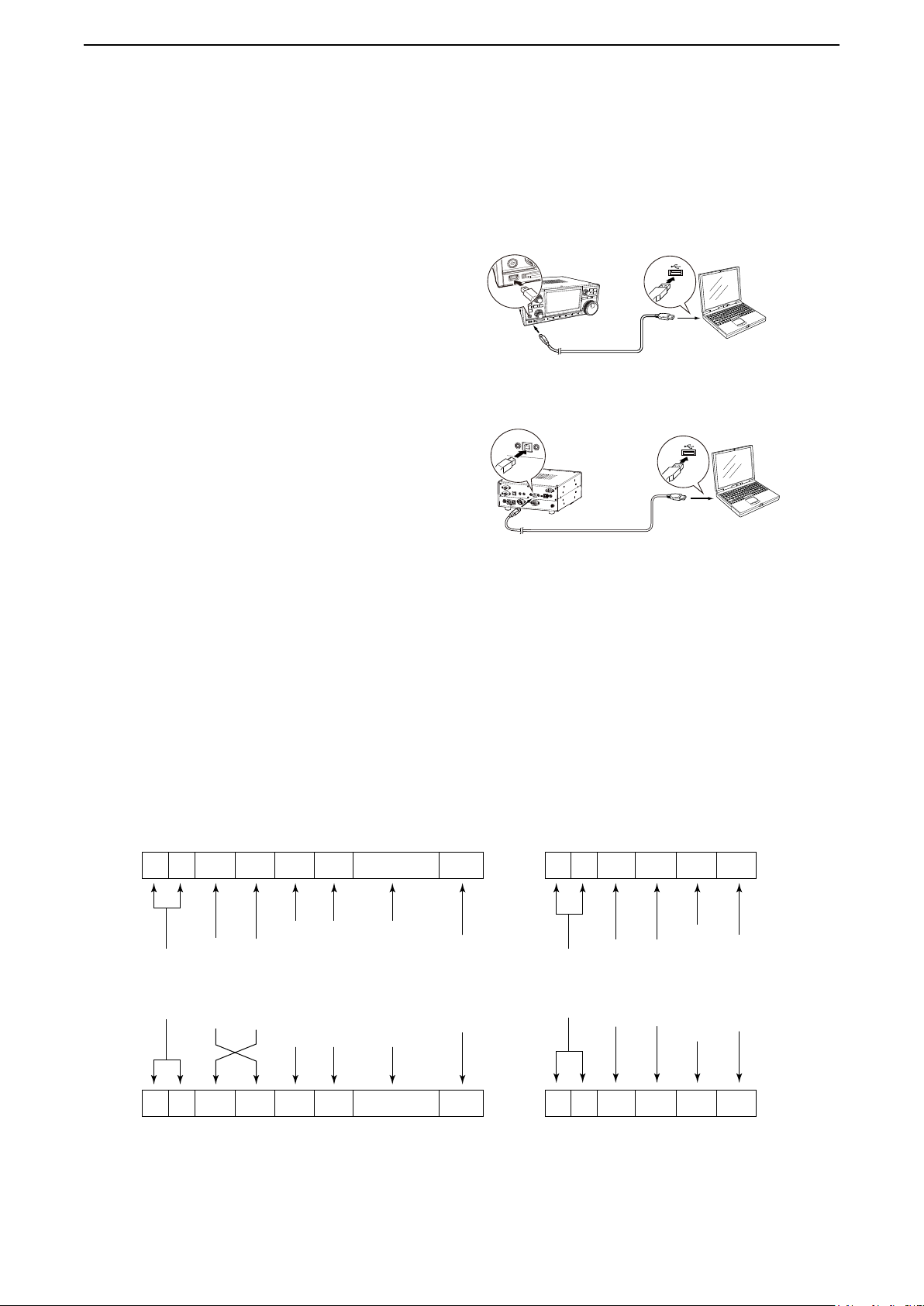
D CI-V connection
The receiver's operating frequency, mode, VFO and
memory selection, can be remotely controlled using a
PC.
• Use a USB cable (A-B (or A-miniB) type, user
supplied) to connect the IC-R8600 and the PC
(controller).
The required USB driver and driver installation guide
can be downloaded from the Icom web site.
Go to “http://www.icom.co.jp/world,” and then click
“Support,” “Firmware Updates / Software downloads”
in sequence.
L The download procedure on the web page may be
changed without notice.
D Preparing
The Icom Communications Interface V (CI-V) is used
for remote control.
To control the receiver, rst set its address, data
communication speed, and transceive function.
These settings are set in Set mode (Refer to the ICR8600 instruction manual).
• Connection example
IC-R8600
(Front panel)
USB cable (A-miniB type)
IC-R8600
(Rear panel)
USB cable (A-B type)
L Make the connection as short as possible. The receiver
may not be recognized by the controller, depending on
the USB cable length.
PC
(Controller)
PC
(Controller)
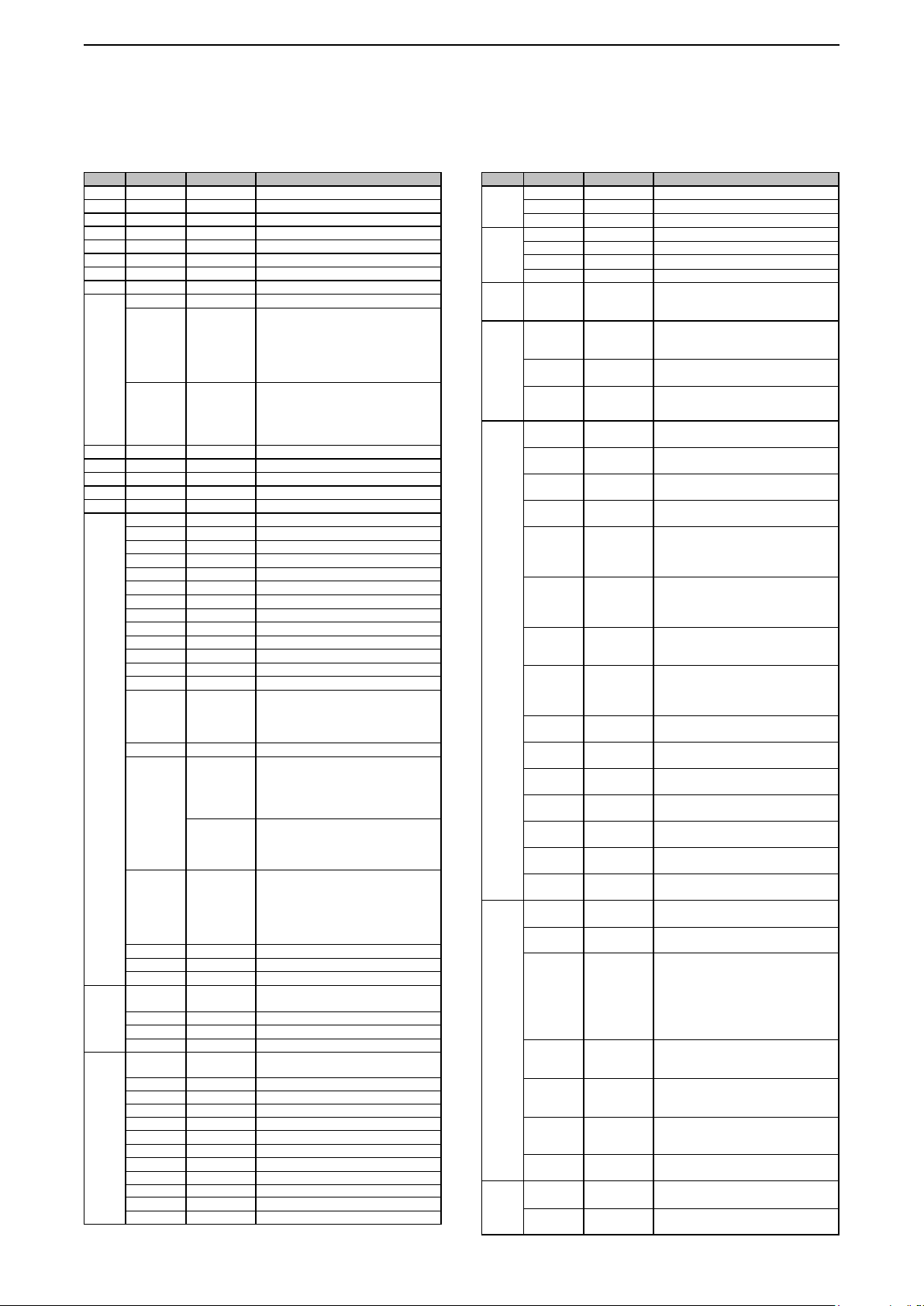
D About the data format
The CI-V system can be written using the following
data formats. Data formats differ according to
command numbers. A data area or sub command is
added for some commands.
Controller to IC-R8600
q w e r t y u
FE FE 96 E0 Cn Sc Data area FD
Preamble
FE FE E0 96 Cn Sc Data area FD
q w e r t y u
IC-R8600 to controller
code (fixed)
Receiver’s
Controller’s
default address
default address
Command number
(see the command table)
Sub command number
BCD code data for
(see command table)
number entry
frequency or memory
code (fixed)
End of message
OK message to controller
FE FE E0 96 FB FD
(fixed)
OK code
Preamble
code (fixed)
FE FE E0 96 FA FD
Receiver’s
Controller’s
default address
default address
NG code
(fixed)
NG message to controller
code (fixed)
End of message
2
Remote control
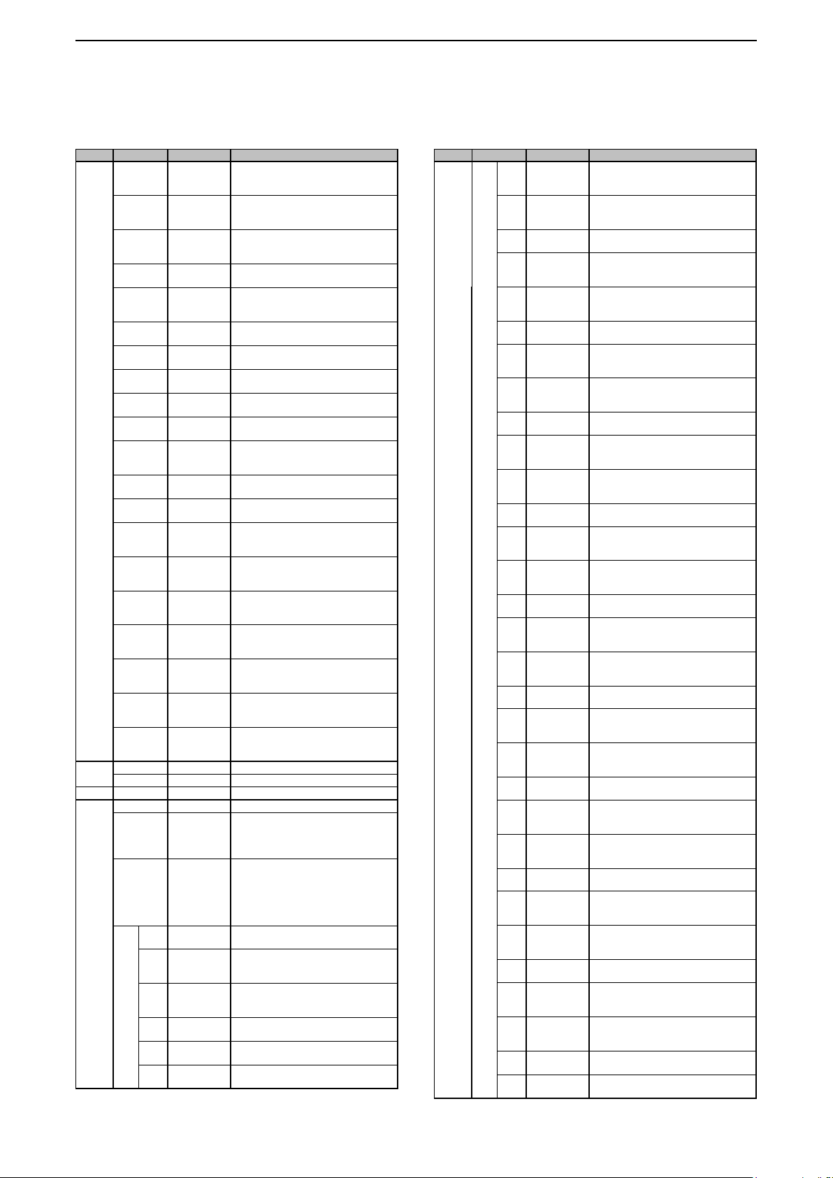
D Command table
Cmd. Sub cmd. Data Description
00 See p. 9 Output the frequency data for transceive
01 See p. 9 Output the receiving mode for transceive
02 See p. 9 Read the band edge frequencies
03 See p. 9 Read the receiving frequency
04 See p. 9 Read the receiving mode
05 See p. 9 Set the receiving frequency
06 See p. 9 Select the receiving mode
07 Select the VFO mode
08 Select the Memory mode
A0 0000 ~ 0102 Select the Memory group
09 Memory write
0A Memory copy to VFO
0B Memory clear
0C Read offset frequency
0D See p. 9 Set offset frequency
0E 00 Scan stop
01 Programmed/memory scan start
02 Programmed scan start
03
04 Auto Memory Write scan start
12 Fine Programmed scan start
13
22 Memory scan start
23 Select memory scan start
24 Mode Select scan start
42 Priority scan start
A0
AA
Ax
B0 Set as non-select channel
B1 Set as select channel
B2 00 ~ 09 Set starting select memory channel for a
D0 Set Scan resume OFF
D1 Set Scan resume ON (Close timer)
D3 Set Scan resume ON (Close & Delay)
0F 10 ~ 12 Read duplex setting
10 Set Simplex
11 Set Duplex –
12 Set Duplex +
10* 00 Send/read the tuning step OFF(in 10 Hz
07 Send/read the 8.33 kHz tuning step
0000 ~ 0199 Select the Memory channel
( 0000 ~ 0099: Normal Memory
(000 0 ~ 0199: Auto Memory Write
( 0000 ~ 0099:
0100: Auto Memory Write channels
0101: Scan Skip channels
0102: Scan edges)
channels/Scan Skip
channels/Scan edges)
channels)
Normal Memory channels
∂F scan start
Fine
∂F scan start
Set the Fix of
Set the Fix of
Set/read the Fix range (x) of ∂F frequency
(1=±5kHz, 2=±10kHz, 3=±20kHz,
4=±50kHz, 5=±100kHz, 6=±500kHz,
7=±1MHz)
( If no selection is performed, the
previously set number by CI-V is set
after turning power ON, otherwise “1” is
automatically set.)
01 ~ 09 Set as select channel
(01=SEL1, 02=SEL2, 03=SEL3,
04=SEL4, 05=SEL5, 06=SEL6,
07=SEL7, 08=SEL8, 09=SEL9)
select memory scan
(00=ALL, 01=SEL1, 02=SEL2,
03=SEL3, 04=SEL4, 05=SEL5,
06=SEL6, 07=SEL7, 08=SEL8,
09=SEL9)
(10=OFF, 11=DUP–, 12=DUP+)
steps)
01 Send/read the 100 Hz tuning step
02 Send/read the 1 kHz tuning step
03 Send/read the 2.5 kHz tuning step
04 Send/read the 3.125 kHz tuning step
05 Send/read the 5 kHz tuning step
06 Send/read the 6.25 kHz tuning step
08 Send/read the 9 kHz tuning step
09 Send/read the 10 kHz tuning step
10 Send/read the 12.5 kHz tuning step
11 Send/read the 20 kHz tuning step
∂F frequency to OFF
∂F frequency to ON
Cmd. Sub cmd. Data Description
10* 12 Send/read the 25 kHz tuning step
11* 00 Send/read Attenuator OFF (0 dB)
12* 00 ~ 02 Select antenna (only 10 kHz –
13 00 Speech all parameters
01 Speech frequency
02 Speech receiving mode
14* 01 0000 ~ 0255 Send/read the AF gain level
02 0000 ~ 0255 Send/read the RF gain level
03 0000 ~ 0255 Send/read the squelch level
06 0000 ~ 0255 Send/read the NR level
07 0000 ~ 0255 Send/read the PBT1 position
08 0000 ~ 0255 Send/read the PBT2 position
09 0000 ~ 0255 Send/read CW pitch
0D 0000 ~ 0255 Send/read the NOTCH position
12 0000 ~ 0255 Send/read the NB level
19 0000 ~ 0255 Send/read the LCD brightness
1B 0000 ~ 0255 Send/read the tone (Bass) level
1C 0000 ~ 0255 Send/read the tone (Treble) level
1D 0000 ~ 0255 Send/read the Scan Speed
1E 0000 ~ 0255 Send/read the Scan Delay
1F 0000 ~ 0255 Send/read the PRIO Interval
15 01 00/01 Read noise or S-meter squelch status
02 0000 ~ 0255 Read the S-meter level
03 Read the meter level in the
04 0000 ~ 0255 Read the center meter level
05 00/01 Read various squelch function’s
17 00/01 Read the S-AM SYNC Indicator
18 00/01 Read the OVF indicator status
16* 02 00/01 Send/read the Preamp status
12 01 ~ 03 Send/read the AGC function status
13 Send/read the 100 kHz tuning step
14 Send/read the programmable tuning step
10 Send/read Attenuator (10 dB)
20 Send/read Attenuator (20 dB)
30 Send/read Attenuator (30 dB)
29.999999 MHz)
(00=ANT1, 01=ANT2, 02=ANT3)
( Signal level + Frequency + Receiving
mode)
(Signal level + Frequency)
L The mode is announced after the
ongoing speech.
(0000=Minimum ~ 0255=Maximum)
(0000=Minimum ~ 0255=Maximum)
(0000=Minimum ~ 0255=Maximum)
(0000=0% ~ 0255=100%)
(0000=Narrow the upper edge,
0128=Center position,
0255=Narrow the lower edge)
(0000=Narrow the upper edge,
0128=Center position,
0255=Narrow the lower edge)
(0000=300 Hz, 0128=600 Hz,
0255=900 Hz) (in 5 Hz steps)
(0000=A lower position,
0128=Center position,
0255=A upper position)
(0000=0% ~ 0255=100%)
(0000=0% ~ 0255=100%)
(0000=–15, 0128=0, 0255=+15)
(0000=–15, 0128=0, 0255=+15)
(0000=1, 0128=16, 0255=30)
(0000=1s, 0128=16s, 0255=30s)
(0000=1s, 0128=8s, 0255=15s)
(00=Close, 01=Open)
(0000=S0, 0120=S9, 0241=S9+60dB)
"AAAABBCC" Format:
AAAA= Absolute signal strength (in
0.1 steps)
BB= Plus or minus sign (0/1=+/–)
CC= Meter type (0/1/2=dBμ/dBμEMF/
dBm)
( 0000= Left edge, 0128= Center,
0255= Right edge)
(including the tone squelch) status
(00=Close, 01=Open)
( 00=Non-synchronous,
01=Synchronous)
(00=OFF, 01=ON)
(00=OFF, 01=ON)
( 01=FAST, 02=MID, 03=SLOW)
3
Remote control
D Command table (Continued)
Cmd. Sub cmd. Data Description
16* 22 00/01 Send/read the Noise blanker function
40 00/01 Send/read the Noise reduction function
41 00/01 Send/read the Auto notch function
43 00/01 Send/read the Tone squelch status
48 00/01 Send/read the Manual notch function
4A 00/01 Send/read the AFC function status
4B 00/01 Send/read the DTCS function status
4C 00/01 Send/read the VSC function status
4F 00/01 Send/read the Twin Peak Filter status
50 00/01 Send/read the Dial lock function status
52 00/01 Send/read the P25 digital squelch
56 00/01 Send/read the DSP lter type
57 00 ~ 02 Send/read the Manual notch width
5B 00/02 Send/read the D-STAR digital squelch
5F 00/01 Send/read the dPMR digital squelch
60 00/01 Send/read the NXDN digital squelch
61 00/01 Send/read the DCR digital squelch
62 00/01 Send/read the dPMR SCRAMBLER
63 00/01 Send/read the NXDN ENCRYPTION
64 00/01 Send/read the DCR ENCRYPTION
18 00 Turn OFF the receiver
01 Turn ON the receiver*
19 00 Read the receiver ID
1A 00*
03* 00 ~ 49 Send/read the selected lter width
04* 00 ~ 13
05* 0001 See p. 10 Send/read the FM audio tone (HPF/
See pp. 11 ~ 14
0002 00 ~ 30 Send/read the FM audio tone (Bass)
0003 00 ~ 30 Send/read the FM audio tone (treble)
0004 00/01 Send/read the de-emphasis (50k)
0005 00/01 Send/read the de-emphasis (15k)
0006 00/01 Send/read the de-emphasis (7k)
status
(00=OFF, 01=ON)
status
(00=OFF, 01=ON)
status
(00=OFF, 01=ON)
(00=OFF, 01=ON)
status
(00=OFF, 01=ON)
(00=OFF, 01=ON)
(00=OFF, 01=ON)
(00=OFF, 01=ON)
(00=OFF, 01=ON)
(00=OFF, 01=ON)
(D.SQL) setting
(00=OFF, 01=NAC)
(00=SHARP, 01=SOFT)
(00=WIDE, 01=MID, 02=NAR)
(D.SQL) setting
(00=OFF, 02=CSQL)
(D.SQL) setting
(00=OFF, 01=COM ID, 02=CC)
(D.SQL) setting
(00=OFF, 01=RAN)
(D.SQL) setting
(00=OFF, 01=UC)
function status
(00=OFF, 01=ON)
function status
(00=OFF, 01=ON)
function status
(00=OFF, 01=ON)
1
Send/read memory channel contents
(AM mode: 00=200 Hz ~ 49=10 kHz,
other than AM mode: 00=50 Hz ~ 40/31
=3600/2700 Hz)
Send/read the selected AGC time constant
(00=OFF,
SSB/CW/FSK modes:
01=0.1 ~ 13=6.0 seconds
AM mode:
01=0.3 ~ 13=8.0 seconds)
LPF) settings
settings
(00=–15 ~ 30=+15)
settings
(00=–15 ~ 30=+15)
(00=OFF, 01=ON)
(00=OFF, 01=ON)
(00=OFF, 01=ON)
Cmd. Sub cmd. Data Description
1A 05* 0007 00 ~ 30 Send/read the WFM audio tone (Bass)
0008 00 ~ 30 Send/read the WFM audio tone (Treble)
0009 See p. 10 Send/read the AM audio tone (HPF/
0010 00 ~ 30 Send/read the AM audio tone (Bass)
0011 00 ~ 30 Send/read the AM audio tone (Treble)
0012 See p. 10 Send/read the SSB audio tone (HPF/
0013 00 ~ 30 Send/read the SSB audio tone (Bass)
0014 00 ~ 30 Send/read the SSB audio tone (Treble)
0015 See p. 10 Send/read the CW audio tone (HPF/
0016 00 ~ 30 Send/read the CW audio tone (Bass)
0017 00 ~ 30 Send/read the CW audio tone (Treble)
0018 See p. 10 Send/read the FSK audio tone (HPF/
0019 00 ~ 30 Send/read the FSK audio tone (Bass)
0020 00 ~ 30 Send/read the FSK audio tone (Treble)
0021 See p. 10 Send/read the D-STAR audio tone
0022 00 ~ 30 Send/read the D-STAR audio tone
0023 00 ~ 30 Send/read the D-STAR audio tone
0024 See p. 10 Send/read the P25 audio tone (HPF/
0025 00 ~ 30 Send/read the P25 audio tone (Bass)
0026 00 ~ 30 Send/read the P25 audio tone (Treble)
0027 See p. 10 Send/read the dPMR audio tone (HPF/
0028 00 ~ 30 Send/read the dPMR audio tone (Bass)
0029 00 ~ 30 Send/read the dPMR audio tone
0030 See p. 10 Send/read the NXDN audio tone (HPF/
0031 00 ~ 30 Send/read the NXDN audio tone (Bass)
0032 00 ~ 30 Send/read the NXDN audio tone
0033 See p. 10 Send/read the DCR audio tone (HPF/
0034 00 ~ 30 Send/read the DCR audio tone (Bass)
0035 00 ~ 30 Send/read the DCR audio tone (Treble)
0036 0000 ~ 0255 Send/read the beep level
0037 00/01 Send/read beep gain limit
settings
(00=–15 ~ 30=+15)
settings
(00=–15 ~ 30=+15)
LPF) settings
settings
(00=–15 ~ 30=+15)
settings
(00=–15 ~ 30=+15)
LPF) settings
settings
(00=–15 ~ 30=+15)
settings
(00=–15 ~ 30=+15)
LPF) settings
settings
(00=–15 ~ 30=+15)
settings
(00=–15 ~ 30=+15)
LPF) settings
settings
(00=–15 ~ 30=+15)
settings
(00=–15 ~ 30=+15)
(HPF/LPF) settings
(Bass) settings
(00=–15 ~ 30=+15)
(Treble) settings
(00=–15 ~ 30=+15)
LPF) settings
settings
(00=–15 ~ 30=+15)
settings
(00=–15 ~ 30=+15)
LPF) settings
settings
(00=–15 ~ 30=+15)
(Treble) settings
(00=–15 ~ 30=+15)
LPF) settings
settings
(00=–15 ~ 30=+15)
(Treble) settings
(00=–15 ~ 30=+15)
LPF) settings
settings
(00=–15 ~ 30=+15)
settings
(00=–15 ~ 30=+15)
(0000=0% ~ 0255=100%)
(00=OFF, 01=ON)
4

Remote control
D Command table (Continued)
Cmd. Sub cmd. Data Description
1A 05* 0038 00/01 Send/read conrmation beep
0039 00/01 Send/read speech language
0040 00/01 Send/read speech speed
0041 00/01 Send/read S-meter level speech
0042 00/01
0043 00/01 Send/read scan speech function
0044 00 ~ 02 Send/read the setting of the speech
0045 00 ~ 02 Send/read the speech recording setting
0046 0000 ~ 0255 Send/read the speech level
0047 00/01
0048 00/01 Send/read the [P.LOCK] key action
0049 00 ~ 02 Send/read the Automatic TS function
0050 00/01 Send/read the AFC limit
0051 00 ~ 02 Send/read the [NOTCH] key action in
0052 00 ~ 02 Send/read the [NOTCH] key action in
0053 00/01 Send/read SSB/CW synchronous tuning
0054 00/01 Send/read the CW normal side setting
0055 00/01 Assign the Screen Capture function to
0056 00/01 Send/read the le format for the Screen
0057 00/01 Send/read the Keyboard type
0058 0000 ~ 0511 Send/read the reference frequency
0059 00 ~ 02 Send/read the receive mode when
0060 00/01 Send/read the RX history log function
0061 00 ~ 02 Send/read the separator for the CSV le
0062 00 ~ 02 Send/read the date format of the CSV le
0063 00/01 Send/read the D-STAR standby beep
0064 00/01 Send/read the DV (D-STAR) mode
0065 00/01 Send/read the call history of received
0066 0000 ~ 0255 Send/read the EMR signal audio output
0067 0040 ~ 0200 Send/read the output ratio of the
0068 00/01 Send/read the signal output from [AF/IF]
0069 0000 ~ 0255 Send/read the AF output level of [AF/IF]
(00=OFF, 01=ON)
(00=English, 01=Japanese)
(00=Slow, 01=Fast)
(00=OFF, 01=ON)
Send/read receiving mode
(00=OFF, 01=ON)
(00=OFF, 01=ON)
output from the external terminals
(00=OFF, 01=Push/Touch, 02=ALL)
(00=OFF, 01=Push/Touch, 02=ALL)
(0000=0% ~ 0255=100%)
Send/read the [SPEECH/LOCK] key action
(00=Push: SPEECH, Hold down: LOCK,
01=Push: LOCK, Hold down: SPEECH)
(00=ALL, 01=KEY)
(00=OFF, 01=LOW, 02=HIGH)
(00=OFF, 01=ON)
the AM mode
(00=Auto, 01=Manual, 02=Auto/Manual)
the SSB mode
(00=Auto, 01=Manual, 02=Auto/Manual)
(00=OFF, 01=ON)
(00=LSB, 01=USB)
[POWER]
(00=OFF, 01=ON)
Capture function
(00=PNG, 01=BMP)
(00=Ten-key, 01=Full Keyboard)
adjustment value
(0000=0% ~ 0511=100%)
[DIAL B] is pushed in the DIGITAL mode
(00=Auto, 01=Digital, 02=Analog)
(00=OFF, 01=ON)
(00=Separator "," Decimal point ".",
01=Separator ";" Decimal point ".",
02=Separator ";" Decimal point ",")
( 00=yyyy/mm/dd, 01=mm/dd/yyyy,
02=dd/mm/yyyy)
(00=OFF, 01=ON)
Automatic Detect function
(00=OFF, 01=ON)
DV (D-STAR) signal from a repeater
(00=ALL, 01=Latest Only)
level
(0000=0% ~ 0255=100%)
speaker output level and headphones
output level
(0040=0.40 ~ 0200=2.00)
(00=AF, 01=IF)
(0000=0% ~ 0255=100%)
speech
Cmd. Sub cmd. Data Description
1A 05* 0070 00/01 Send/read the audio output setting for
0071 00/01 Send/read the Beep and Speech audio
0072 0000 ~ 0255 Send/read the IF output level of [AF/IF]
0073 00/01 Send/read the signal output from [USB]
0074 0000 ~ 0255 Send/read the AF output level of [USB]
0075 00/01 Send/read the audio output setting for
0076 00/01 Send/read the Beep and Speech audio
0077 0000 ~ 0255 Send/read the IF output level of [USB]
0078 00/01 Send/read the signal output from [USB]
0079 00 ~ 03 Send/read the data transfer rate (Baud
0080 00/01 Send/read the data transfer rate (Baud
0081 00/01 Send/read the signal output from [USB]
0082 0000 ~ 0255 Send/read the AF output level of [USB]
0083 00/01 Send/read the audio output setting for
0084 00/01 Send/read the Beep and Speech audio
0085 0000 ~ 0255 Send/read the IF output level of [USB]
0086 00/01 Send/read the signal output from [USB]
0087 00 ~ 03 Send/read the data transfer rate (Baud
0088 00/01 Send/read the data transfer rate (Baud
0089 00/01 Send/read the signal output from [LAN].
0090 00/01 Send/read the audio output setting for
5
[AF/IF]
(00=OFF (OPEN): The squelch is always
01=ON: The squelch opens and closes,
according to the squelch and
signal levels.)
output status of [AF/IF]
(00=OFF, 01=ON)
(0000=0% ~ 0255=100%)
on the front panel
(00=AF, 01=IF)
on the front panel
(0000=0% ~ 0255=100%)
[USB] on the front panel
(00=OFF (OPEN): The squelch is
01=ON: The squelch opens and closes,
according to the squelch and
signal levels.)
output status of [USB] on the front panel
(00=OFF, 01=ON)
on the front panel
(0000=0% ~ 0255=100%)
on the front panel
( 00=An FSK decoded signal,
01=A D-STAR data)
rate) of decoded FSK signals from
[USB] on the front panel
(00=4800 bps, 01=9600 bps,
02=19200 bps, 03=38400 bps)
rate) of decoded D-STAR data from
[USB] on the front panel
(00=4800 bps, 01=9600 bps)
on the rear panel
(00=AF, 01=IF)
on the rear panel
(0000=0% ~ 0255=100%)
[USB] on the rear panel
(00=OFF (OPEN):
01=ON: The squelch opens and closes,
according to the squelch and
signal levels.)
output status of [USB] on the rear panel
(00=OFF, 01=ON)
on the rear panel
(0000=0% ~ 0255=100%)
on the rear panel.
( 00=An FSK decoded signal,
01=A D-STAR data)
rate) of decoded FSK signals from
[USB] on the rear panel
(00=4800 bps, 01=9600 bps,
02=19200 bps, 03=38400 bps)
rate) of decoded D-STAR data from
[USB] on the rear panel
(00=4800 bps, 01=9600 bps)
(00=AF, 01=IF)
[LAN]
(00=OFF (OPEN): The squelch is
01=ON: The squelch opens and closes,
according to the squelch and
signal levels.)
opened.
always opened
The squelch is always
opened.
always opened.
Remote control
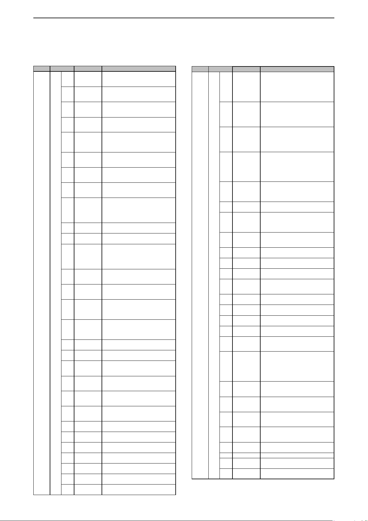
D Command table (Continued)
Cmd. Sub cmd. Data Description
1A 05* 0091 00/01 Send/read the Speech audio output
0092 00/01 Send/read the CI-V transceive function
0093 0000 ~ 0223 Send/read the CI-V transceive address
0094 00/01 Send/read the Data Echo Back function
0095 00/01 Read the CI-V USB (Rear) port setting
0096 00/01 Send/read the Data Echo Back function
0097 00/01
0098 0000 ~ 0255 Send/read the voltage level output from
0099 00 ~ 02 Send/read the receiver’s reference
0100 00/01 Send/read the DHCP function
0101 Set the static IP address
0102 Read the dynamic IP address
0103 01 ~ 30 Send/read the subnet mask to connect
0104 Send/read the default gateway setting
0105 Send/read the primary DNS server
0106 Send/read the secondary DNS server
0107 See p. 10 Send/read the network name
0108 00/01 Send/read the network control setting.
0109 00/01 Send/read the Power OFF Setting (for
0110 000001 ~
065535
0111 000001 ~
065535
0112 000001 ~
065535
0113 00/01 Send/read the internet access line
0114 See p. 10 Send/read the nickname of the IC-R8600
0115 0000 ~ 0255 Send/read the LCD backlight brightness
0116 0000 ~ 0255 Send/read the LED brightness
0117 00/01 Send/read the display background type
0118 00/01 Send/read the Meter Peak Hold function
0119 00/01 Send/read the Memory name display
status of [LAN]
(00=OFF, 01=ON)
setting
(00=OFF, 01=ON)
USB/LAN -> REMOTE) setting (in Hexadecimal)
(
(0000=00h ~ 0223=DFh)
for the [USB] (Front) CI-V port
(00=OFF, 01=ON)
(00=Connect to [REMOTE],
01=Disconnect from [REMOTE])
(Read only)
for the [USB] (Rear) CI-V port
(00=OFF, 01=ON)
Send/read the signal output from [METER]
( 00=Signal strength
01=Signal strength and squelch level)
[METER]
(0000=0% ~ 0255=100%)
frequency signal source
( 00=IN Uses an external reference signal,
01=OFF,
02= Outputs the internal reference signal.)
(00=OFF, 01=ON)
(0000000000000001 ~ 0255025502550254)
(0000000000000001 ~ 0255025502550254)
( The automatically obtained address (If
the DHCP is set to ON), or a manually
set static IP address.)
to your PC or LAN
(01=1 bit ~ 30=30 bit)
(0000 0000 0000 0001 ~
0255 0255 0255 0254, FF (blank))
address
(0000 0000 0000 0001 ~
0255 0255 0255 0254, FF(blank))
address
(0000 0000 0000 0001 ~
0255 0255 0255 0254, FF(blank))
(Up to 15 characters)
(00=OFF, 01=ON)
Remote Control)
(00=Shutdown only, 01=Standby/Shutdown)
Send/read the UDP port number for the
control signal transfer
(1 ~ 65535)
Send/read the UDP port number for the
serial data transfer
(1 ~ 65535)
Send/read the UDP port number for the
audio signal transfer
(1 ~ 65535)
(00=FTTH, 01=ADSL/CATV)
(1 ~ 16 characters)
(0000=0% ~ 0255=100%)
(0000=0% ~ 0255=100%)
(00=A, 01=B)
(00=OFF, 01=ON)
(00=OFF, 01=ON)
,
Cmd. Sub cmd. Data Description
1A 05* 0120 00/01 Send/read the group name display
0121 00/01 Send/read the Notch lter width display
0122 00/01 Send/read the digital TWIN PBT shift
0123 00/01 Send/read the digital IF lter width and
0124 00 ~ 03 Send/read the digital signal information
0125 00/01 Send/read the P25 ID display type
0126 00 ~ 03 Send/read the Screen Saver activation
0127 00/01 Send/read the opening message display
0128 p.10 Send/read the opening comment
0129 00/01 Send/read the display language
0130 00/01 Send/read the system language
0131 20000101 ~
20991231
0132 0000 ~ 2359 Send/read the current time
0133 00/01 Send/read the NTP function
0134 See p. 10 Send/read the NTP server address
0135 See p. 10 Send/read the UTC offset time
0136 00 ~ 02 Send/read the scope peak level holding
0137 00 ~ 02 Send/read the scope center position
0138 00/01 Send/read the scope marker position
0139 00/01 Send/read the scope Video Band Width
0140 00 ~ 03 Send/read the FFT scope waveform
0141 00/01 Send/read the scope outline waveform
0142 See p. 10 Send/read the scope waveform (current)
0143 See p. 10 Send/read the waveform outline color
0144 See p. 10 Send/read the scope waveform (Max
0145 See p. 10 Send/read the pointer color for the RX
function
(00=OFF,
01=ON The group name is displayed
when you change the memory
channel group)
function
(00=OFF,
The lter width is displayed when
01=ON
you select the Manual Notch.)
value display function
( 00=OFF,
01=ON The shift value is displayed
while rotating [DIAL C].)
shift value display function
( 00=OFF,
01=ON The lter width and shift value
are displayed when you change
the IF lter.)
display function
( 00=OFF, 01=Normal, 02=RX Hold,
03=Hold)
(00=Decimal, 01=Hexadecimal)
time
00=OFF, 01=15 minutes, 02=30 minutes,
(
03=60 minutes)
function
(00=OFF, 01=ON)
(Up to 10 characters)
(00=English, 01=Japanese)
(00=English, 01=Japanese)
Send/read the date (Year/Month/Day)
(20000101 "2000/1/1" ~
20991231 "2099/12/31")
(0000 "00:00" ~ 2359 "23:59")
(00=OFF, 01=ON)
(Up to 64 characters)
(–14:00 ~ +14:00 (in 5 minutes steps))
function
(00=OFF, 01=10 seconds Hold, 02=ON)
(00=Filter Center,
01=Carrier Point Center,
02= Carrier Point Center
(with absolute frequency))
(Only in the Center mode)
(00=Filter Center, 01=Carrier Point)
(Only in the Fixed mode)
(VBW)
(00=Narrow, 01=Wide)
averaging function
(00=OFF, 01=2, 02=3, 03=4)
display
(00=Fill, 01=Fill+Line)
color
hold) color
Marker
6

Remote control
D Command table (Continued)
Cmd. Sub cmd. Data Description
1A 05* 0146 See p. 10 Send/read the pointer color for the Peak
0147 00/01 Send/read the scope Water fall display
0148 00 ~ 02 Send/read
0149 00 ~ 02 Send/read the scope Waterfall height for
0150 00 ~ 07 Send/read the signal level that the
0151 00/01 Send/read the Waterfall Marker Auto-
0152 00 ~ 60 Send/read the difference of amplitude
0153 00 ~ 80 Send/read the threshold level for the
0154 00/01 Send/read the spectrum waveform peek
0155 00 ~ 02 Send/read the period of time of the
0156 00/01 Send/read the Skip function setting
0157 00 ~ 02 Send/read the Auto Memory Write Scan
0158 00/01
0159 00/01 Send/read the scan operation when
0160 00 ~ 03 Send/read the FSK FFT scope
0161 See p. 10 Send/read the color of the FSK FFT
0162 00/01 Send/read the FSK Letter Code
0163 00/01
0164 00/01
0165 00/01 Send/read the FSK log time stamp
0166 See p. 10 Send/read the text font color for
0167 See p. 10 Send/read the text font color for the
0168 00/01 Send/read FSK log function setting
0169 00/01 Send/read FSK log le type
0170 00/01 Send/read the FSK RX frequency
0171 00 ~ 03 Send/read the FSK mark frequency
0172 00 ~ 04 Send/read the FSK shift width
0173 00/01 Send/read the recording setting
0174 00/01 Send/read the File Split function setting
0175 00 ~ 03 Send/read the player skip time
Marker
(00=OFF, 01=ON)
the scope Waterfall speed
(00=Slow, 01=Mid, 02=Fast)
the Expand scope screen
(00=Small, 01=Mid, 02=Large)
scope Waterfall displays a peak color
(00=Grid 1, 01=Grid 2, 02=Grid 3,
03=Grid 4, 04=Grid 5, 05=Grid 6,
06=Grid 7, 07=Grid 8)
hide function setting
(00=OFF, 01=ON)
between the peak signal and nearby
signals
(00=0 dB ~ 60=60 dB)
Peak signal detection
(00=–80 dB ~ 80=0 dB)
search type
(00=Real time, 01=Max. Hold)
Temporary Skip timer
( 00=5 minutes, 01=10 minutes,
02=15 minutes)
(00=OFF, 01=ON)
starting option
(00=OFF, 01=Displays the dialog, 02=ON)
Send/read the SCAN screen display option
(00=OFF, 01=ON)
MAIN DIAL is rotated
(00=OFF, 01=Up/Down)
waveform averaging function setting
(00=OFF, 01=2, 02=3, 03=4)
scope waveform
(000000000000 ~ 025502550255)
Decoding function setting
(00=OFF, 01=ON)
Send/read the FSK decoder new line code
(00=CR,LF,CR+LF, 01=CR+LF)
Send/read the FSK log time stamp (Time)
(00=Local, 01=UTC)
(Frequency)
(00=OFF, 01=ON)
received FSK signal
time stamp
(00=OFF, 01=ON)
(00=Text, 01=HTML)
(00=Mark (Space), 01=Mark/Space center)
(00=1275, 01=1500, 02=1615, 03=2125)
(00=170, 01=200, 02=425, 03=800, 04=850)
(00=Always, 01=Squelch Auto)
(00=OFF, 01=ON)
( 00=3 seconds, 01=5 seconds, 02=10
seconds, 03=30 seconds)
Cmd. Sub cmd. Data Description
1A 05* 0176 00 ~ 09 Send/read the Noise Blanker depth
0177 0000 ~ 0255 Send/read the Noise Blanker width
0178 00/01 Send/read the Memory group type
0179 00/01
0180 00 ~ 03 Send/read the meter type
0181 00/01 Selects the mute state for the Encryption
07* 00/01
08 Read the power supply voltage
09* 00/01
0A 00 ~ 02 Read the date and time update result
1B* 01 See p. 14 Send/read the TSQL tone frequency
02 See p. 14 Send/read the DTCS code
03 000 ~ FFF Send/read the P25 NAC
07 00 ~ 99 Send/read the D-STAR CSQL code
08 001 ~ 255 Send/read the dPMR COM ID
09 00 ~ 63 Send/read the dPMR CC
0A 00 ~ 63 Send/read the NXDN RAN
0B 001 ~ 511 Send/read the DCR UC
0C 00001 ~ 32767 Send/read the dPMR scrambler key
0D 00001 ~ 32767 Send/read the NXDN encryption key
0E 00001 ~ 32767 Send/read the DCR encryption key
1C* 02 00/01 Send/read the Monitor function
1D* 00/02 Send/read the REMOTE function setting
20 00 00* 00/01
01 See p. 15 Output the D-STAR Call sign setting for
02 See p. 15 Read the D-STAR Call sign contained in
01 00* 00/01 Send/read the D-STAR message output
01 See p. 15
02 See p. 15 Read the D-STAR message contained
02 00* 00/01
01 See p. 15
02 See p. 15 Read the D-STAR RX status
03 00* 00/01 Send/read the D-STAR RX GPS/D-PRS
01
See pp. 16 ~ 17
02
04 00* 00/01 Send/read the D-STAR RX GPS/D-PRS
05 00* 00/01 Send/read the D-STAR RX CSQL code
06 00* 00/01 Send/read the P25 ID output setting
See pp. 16 ~ 17
01 See p. 17 Output the D-STAR RX GPS/D-PRS
02 See p. 17
01 See p. 18 Output the D-STAR RX CSQL code for
02 See p. 18 Read the D-STAR RX CSQL code
01 See p. 18 Output the P25 ID for transceive
02 See p. 18 Read the P25 ID
(Noise reducing level)
(00=1 ~ 09=10)
(Blanking period)
(0000=1 ~ 0255=100)
(00=Current group, 01=All groups)
Send/read the scanning Memory group type
(00=Current group, 01=All groups)
(00=S, 01=dBμ, 02=dBμ EMF, 03=dBm)
function in the NXDN mode.
(00=OFF, 01=ON)
Send/read the IP+ function
(00=OFF, 01=ON)
( You can remotely check the power
supply voltage in 0.1 V steps.)
Send/read the connection status of NTP server
(00=Stop, 01=Start)
(00=Updating, 01=Succeed, 02=Failed)
(First 4 bits in each byte are xed to "0.")
(00=OFF, 01=ON)
(00=OFF, 02=ON)
Send/read the D-STAR Call sign output setting
(00=Transceive OFF, 01=Transceive ON)
transceive
the received signal
setting
(00=Transceive OFF, 01=Transceive ON)
Output the D-STAR message for transceive
in the received signal
Send/read the D-STAR RX status output
setting
(00=Transceive OFF, 01=Transceive ON)
Output the D-STAR RX status for transceive
data output setting
(00=Transceive OFF, 01=Transceive ON)
Output the D-STAR RX GPS/D-PRS
data for transceive
Read the D-STAR RX GPS/D-PRS data
message output setting
(00=Transceive OFF, 01=Transceive ON)
message for transceive
Read the D-STAR RX GPS/D-PRS message
output setting
(00=Transceive OFF, 01=Transceive ON)
transceive
(00=Transceive OFF, 01=Transceive ON)
7
 Loading...