

Page 1
INSTRUCTION MANUAL
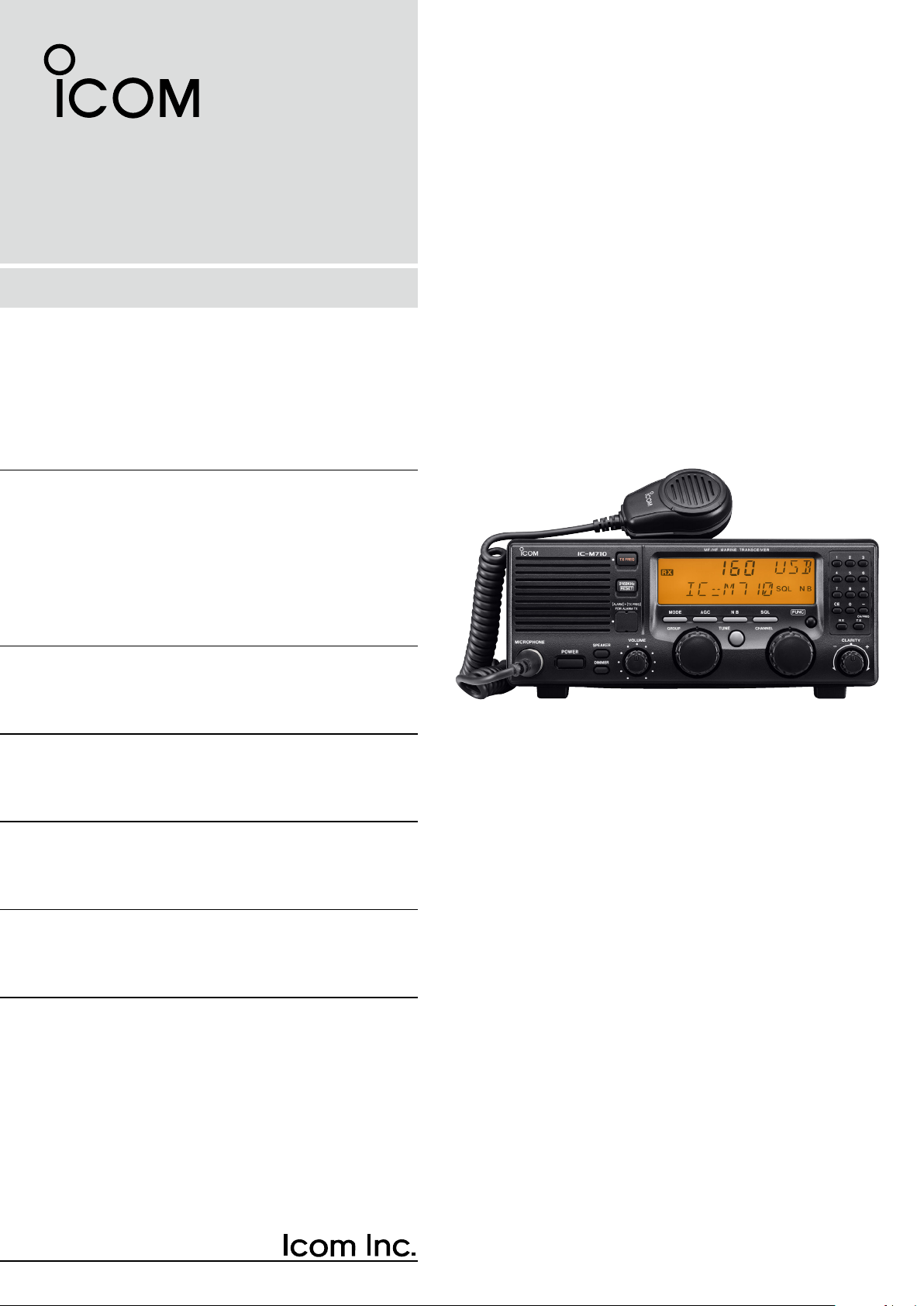
HF MARINE TRANSCEIVER
iM710
Page 2

IMPORTANT
DISPOSAL
READ THIS INSTRUCTION MANUAL CAREFULLY
before attempting to operate the transceiver.
SAVE THIS INSTRUCTION MANUAL—This instruction manual contains important safety and operating
instructions for the IC-M710.
EXPLICIT DEFINITIONS
The explicit definitions described below apply to this
instruction manual.
WORD DEFINITION
RWARNING
CAUTION
NOTE
Personal injury, fire hazard or electric
shock may occur.
Equipment damage may occur.
If disregarded, inconvenience only. No risk
of personal injury, fire or electric shock.
PRECAUTIONS
The crossed-out wheeled-bin symbol on
your product, literature, or packaging reminds you that in the European Union, all
electrical and electronic products, batteries, and accumulators (rechargeable bat-
teries) must be taken to designated
collection locations at the end of their working life. Do
not dispose of these products as unsorted municipal
waste. Dispose of them according to the laws in your
area.
Icom, Icom Inc. and the Icom logo are registered trademarks of
Icom Incorporated (Japan) in Japan, the United States, the United
Kingdom, Germany, France, Spain, Russia, Australia, New Zealand,
and/or other countries.
RWARNING! NEVER connect the transceiver di-
rectly to an AC outlet. This may pose a fire hazard or
result in an electric shock.
RWARNING! NEVER mount the transceiver over-
head. The weight of the transceiver is approximately
7.8 kg. (17.4 lb), but its apparent weight will increase
several fold due to wave shocks and vibration. The
transceiver must be mounted on a flat hard surface
only.
NEVER connect a power source of more than 16 V
DC, such as a 24 volt battery. This connection will ruin
the transceiver.
NEVER place the transceiver where normal operation of the ship or vehicle may be hindered or where it
could cause bodily injury.
NEVER allow children to play with equipment containing a radio transmitter.
NEVER expose the transceiver to rain, snow or any
liquids.
NEVER install the IC-M710 into a positive-grounding
ship. Such a connection might blow fuses, and is not
usable.
DO NOT use chemical agents such as benzene or alcohol when cleaning, as they can damage the transceiver’s surfaces.
i
In maritime mobile operation, KEEP the transceiver
and microphone as far away as possible (at least 1 m)
from the magnetic navigation compass to prevent erroneous indications.
USE an Icom microphone and/or handset only (supplied or optional). Other brands may have different pin
assignments and may damage the transceiver.
DO NOT use or place the transceiver in areas with
temperatures below –20°C (–4°F) or above +60°C
(+140°F).
DO NOT connect the transceiver to a power source
using reverse polarity. This connection will not only
blow fuses but may also damage the transceiver.
DO NOT place the transceiver in excessively dusty environments, or in direct sunlight.
DO NOT place the transceiver against walls, or putting
anything on top of the transceiver. This will obstruct
heat dissipation.
Icom is not responsible for the destruction, damage to, or
performance of any Icom or non-Icom equipment, if the
malfunction is because of:
• Force majeure, including, but not limited to, fires,
earthquakes, storms, floods, lightning, other natural
disasters, disturbances, riots, war, or radioactive
contamination.
• The use of Icom transceivers with any equipment that is
not manufactured or approved by Icom.
Page 3

TABLE OF CONTENTS
IMPORTANT ······························································i
PRECAUTIONS ·························································i
EXPLICIT DEFINITIONS ············································ i
DISPOSAL ·································································i
TABLE OF CONTENTS ············································ ii
1 OPERATING RULES AND GUIDELINES ·············1
2 PANEL DESCRIPTION ······································ 2–5
■ Front panel ··························································2
■ Display ································································5
3 SELECTING A CHANNEL/FREQUENCY ·········6–8
■ Selecting a channel ············································· 6
D Using the channel selector ······························ 6
D Using the keypad ············································ 7
D Using scan function ········································· 7
■ Selecting a frequency ·········································· 8
D Using the channel selector ······························ 8
D Using the keypad ············································ 8
4 RECEIVE AND TRANSMIT ·····························9–11
■ Basic voice receive and transmit ·························9
■ Functions for transmit ·········································· 9
D Transmit frequency check ······························· 9
D Transmit power selection ································ 9
■ Functions for receive ········································· 10
D Squelch function ··········································· 10
D Noise blanker ················································ 10
D AGC OFF function ········································ 10
D RF gain setting ·············································· 10
D Clarity control ················································ 10
■ CW operation (Depends on versions) ···············11
■ FSK operation (Depends on versions) ··············11
5 USER CHANNEL PROGRAMMING ···················· 12
■ Programming a frequency ·································12
D Receive Frequency ······································· 12
D Transmit frequency ······································· 12
D Channel name ··············································· 12
6 SET MODE ····················································· 13–15
■ Set mode operation ···········································13
■ Set mode contents ············································13
7 CONNECTIONS AND INSTALLATION ········· 16–22
■ Connections on the rear panel ··························16
■ Unpacking ·························································16
■ Connector information ·······································17
■ Ground connection ············································19
■ Power source ····················································19
■ Antenna ····························································· 20
D MN-100/MN-100L ANTENNA MATCHERS 20
D AT-130 AUTOMATIC ANTENNA TUNER·····20
D Non-Icom tuner ············································· 20
■ Mounting ···························································21
D Mounting location ·········································· 21
D Mounting example ········································· 21
D Transceiver dimensions ································ 21
■ Disassembling the transceiver ··························22
D Opening the case ·········································· 22
■ Fuse replacement ·············································22
D DC power cable fuse ·····································22
D Circuitry fuse ················································· 22
8 TROUBLESHOOTING ········································· 23
9 SPECIFICATIONS AND OPTIONS ·····················24
■ Specifications ····················································24
D GENERAL ····················································· 24
D TRANSMITTER ············································ 24
D RECEIVER ···················································· 24
■ Options ······························································ 24
ii
Page 4

1
OPERATING RULES AND GUIDELINES
❑ CALL PROCEDURES
Calls must be properly identified and time limits must
be respected.
q Give your call sign each time you call another ves-
sel or coast station. If you have no call sign, identify
your vessel name and the name of the licensee.
w Give your call sign at the end of each transmission
that lasts more than 3 minutes.
e You must break and give your call sign at least once
every 15 minutes. during long ship-to-shore calls.
r Keep your unanswered calls short, less than 30
seconds.
Do not repeat a call for 2 minutes.
t Unnecessary transmissions are not allowed.
❑ PRIORITIES
q Read all rules and regulations pertaining to priori-
ties and keep an up-to-date copy handy. Safety and
distress calls take priority over all others.
w False or fraudulent distress calls are prohibited and
punishable by law.
❑ PRIVACY
q Information overheard but not intended for you can-
not be lawfully used in any way.
w Indecent or profane language is prohibited.
❑ LOGS
q All distress, emergency and safety calls must be re-
corded in complete detail. Log data activity is usually recorded in 24 hour time. Universal Time (UTC)
is frequently used.
w Adjustments, repairs, channel frequency changes
and authorized modifications affecting electrical
operation of the equipment must be kept in the
maintenance log; entries must be signed by the authorized licensed technician performing or supervising the work.
❑ RADIO LICENSES
(1) SHIP STATION LICENSE
You must have a current radio station license before
using the transceiver. It is unlawful to operate a ship
station which is not licensed.
Inquire through your dealer or the appropriate government agency for a Ship-Radiotelephone license application. This government-issued license states the call
sign which is your craft’s identification for radio purposes.
(2) OPERATOR’S LICENSE
A Restricted Radiotelephone Operator Permit is the license most often held by small vessel radio operators
when a radio is not required for safety purposes.
The Restricted Radiotelephone Operator Permit must
be posted or be kept with the operator. Only a licensed
radio operator may operate a transceiver.
However, non-licensed individuals may talk over a
transceiver if a licensed operator starts, supervises,
and ends the call, and makes the necessary log entries.
Keep a copy of the current government rules and regulations handy.
1
Page 5
■ Front panel
MICROPHONE
POWER
VOLUME
TX FREQ
2182KHz
RESET
MODE
TUNE
SSB RADIO TELEPHONE
AGC SQL
CLARITY
NB
SPEAKER
[ALARM] [TX FREQ]+
FOR ALARM TX
DIMMER
GROUP CHANNEL
123
456
789
CE
RX TX
0
CH/F/REQ
iM 710
FUNC
–
q
w
er
t
y
u
i
!0
o
This function is not installed
in the IC-M710.
PANEL DESCRIPTION
2
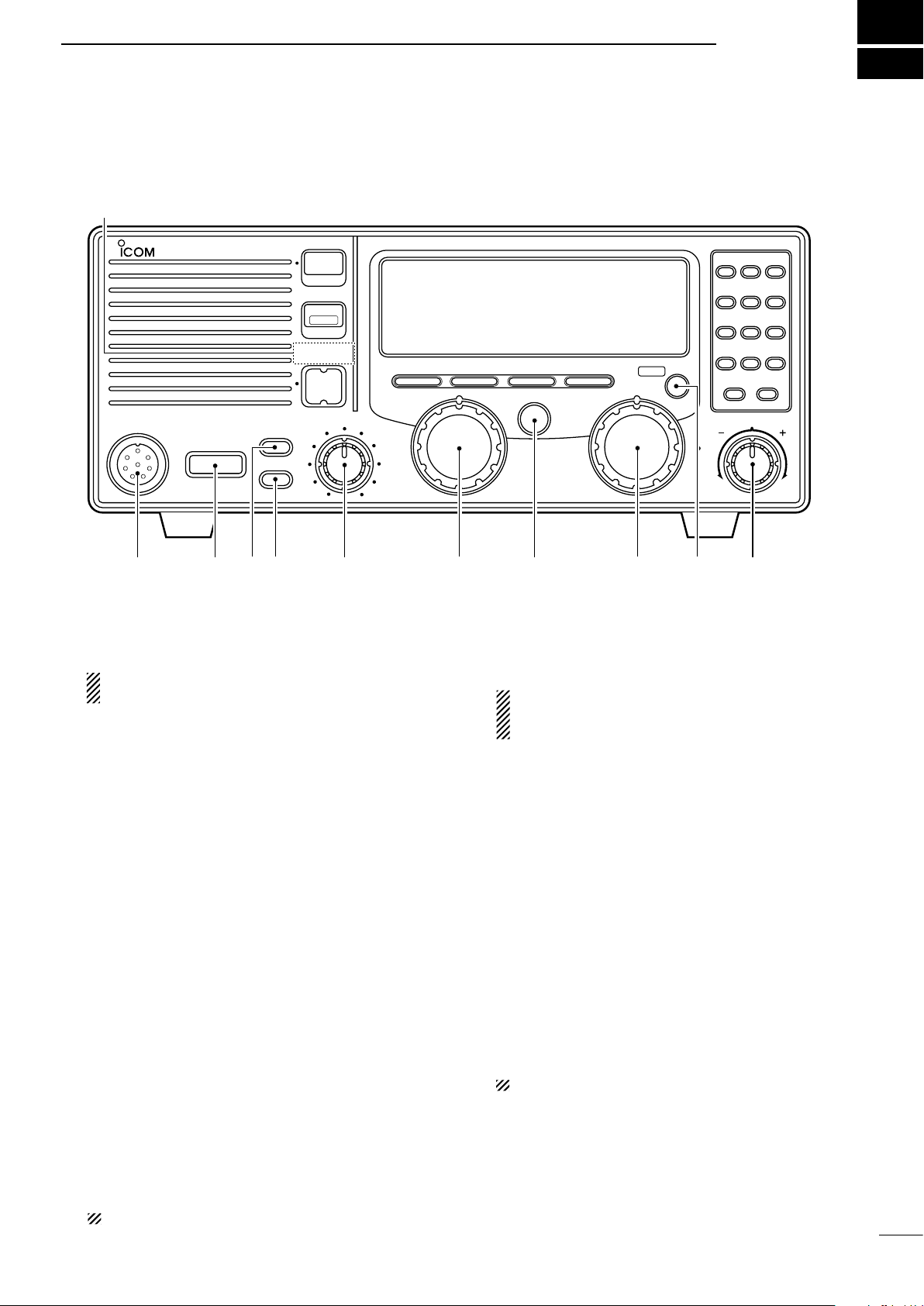
q MICROPHONE CONNECTOR (p. 17)
Accepts the supplied microphone or an optional
handset.
NOTE: No audio is output to the speaker when
the microphone or handset is not connected.
w POWER SWITCH [POWER]
Turns power ON or OFF.
e SPEAKER SWITCH [SPEAKER]
Turns the speaker ON or OFF.
• “è” appears in the display while the speaker is turned
OFF.
• Any external speaker connected to the rear panel is
not turned OFF.
r DISPLAY INTENSITY SWITCH [DIMMER]
➥ Turns the display backlighting ON or OFF.
➥
Push [FUNC], and then rotate the channel selector
dial to set the intensity level while pushing and hold
ing
t VOLUME CONTROL [VOLUME]
Adjusts the audio output level.
• No sound is output to the speaker when:
- A microphone is not connected.
- The [SPEAKER] switch is turned ON.
- The [SQL] switch is turned ON and no signal is being
received.
y GROUP CHANNEL SELECTOR [GROUP]
Selects groups in 20 channels steps and ITU ma-
rine channel groups.
[DIMMER].
u ANTENNA TUNE SWITCH [TUNE] (p. 9)
Tunes the external tuner to the antenna.
• Activates only when an optional antenna tuner such as
Icom’s AT-130 is connected.
NOTE: When selecting “Automatic tuning” in the
set mode, pushing this switch is not necessary
to tune the antenna. (p. 13)
i CHANNEL SELECTOR [CHANNEL] (p. 6)
➥ Selects an operating channel within the selected
channel group.
• User channels can be selected from 1 to 160 (max.)
in sequence regardless of the channel group.
➥ Changes the operating frequency after [CE] is
pushed (while “►”appears).
• The changed frequency is not programmed in this
way.
o FUNCTION SWITCH [FUNC]
-
After pushing activates the secondary functions of
these switches:
- [SQL] ········ Starts and stops scan (p. 7).
- [RX]··········· Sets RF gain (p. 10).
- [TX] ··········· Selects transmit power (p. 9).
- [CE]···········
NOTE:
!0 CLARITY CONTROL [CLARITY] (p. 10)
Shifts the receive frequency ±150 Hz for clear re-
ception of an off frequency signal.
Reprograms the channel name (p. 12).
Function availability depends on vesions.
NOTE: Some versions have no ITU channels.
2
Page 6
2
CE
RX
TX
−
CH/FREQ
1
0
to
PANEL DESCRIPTION
■ Front panel (Continued)
in the IC-M710.
!2!3!4!5!6!7This function is not installed
MICROPHONE
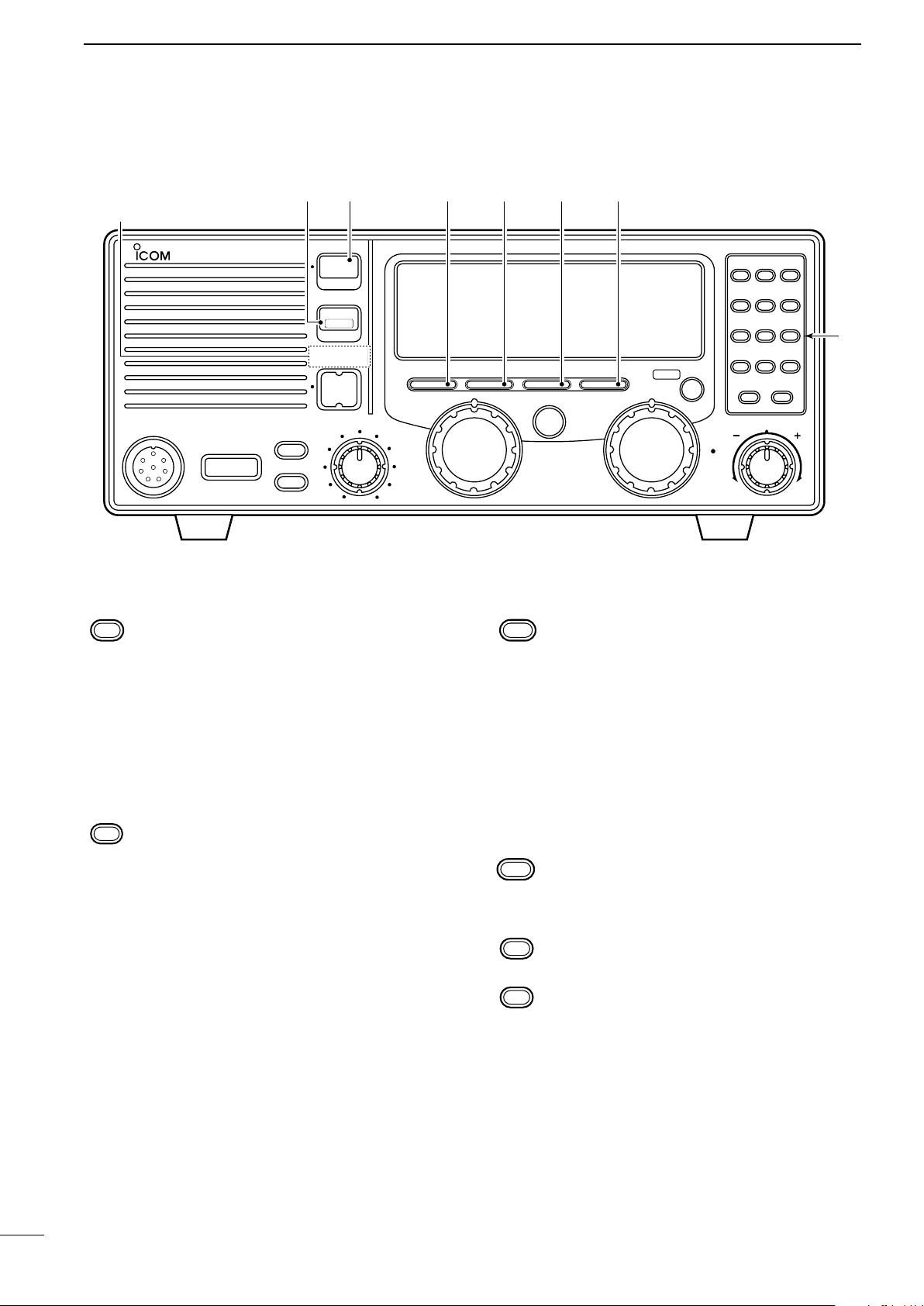
!1 KEYPAD
• Enters the selected channel number (or frequency) for direct channel selection. (p. 7)
• Stores a receive frequency into a user channel or ITU simplex channel when:
- pushing [CE] (“►” appears)
- entering the desired frequency via the key-
pad
- pushing and holding [RX] (p. 12)
• Adjusts the RF gain after pushing [FUNC] to
reduce the receiver sensivity. (p. 10)
• Stores a transmit frequency into a user channel (except General version) when:
- pushing [TX] (“$” blinks)
- pushing [CE] (“►” appears)
- entering the desired frequency via the key-
pad
- pushing and holding [TX] (p. 12)
• Selects the transmit output power after pushing [FUNC]. (p. 9)
POWER
iM 710
SPEAKER
DIMMER
TX FREQ
2182KHz
RESET
[ALARM] [TX FREQ]+
FOR ALARM TX
VOLUME
SSB RADIO TELEPHONE
MODE
GROUP CHANNEL
AGC SQL
NB
TUNE
• Toggles the channel number input or frequency input. (p. 8)
- “►” appears when frequency input is se-
lected.
- The channel selector and keypad changes
the frequency while “►” appears.
• Clears the entered digit and retrieves the previous channel (or frequency) while entering
numbers. (p. 7)
• Enters the name programming condition after
pushing [FUNC] for changing the channel
name. (p. 12)
• Toggles the channel or frequency indications.
(p. 6)
• Enters “–” for ITU simplex channels. (p. 7)
• Enter channel number with up to 4 or 5 digits
when “►” does not appear. (p. 7)
• Enter the frequency with up to 6 digits when
“►” appears. (p. 8)
FUNC
123
456
789
CE
0
RX TX
CLARITY
–
!1
CH/F/REQ
3
Page 7

PANEL DESCRIPTION
2
!2 SQUELCH SWITCH [SQL] (p. 10)
➥ Activates the voice squelch function to reject
undesired background noise while no signal is
being received.
• The squelch opens only when the received
signal contains voice or FSK components.
➥ Starts and stops the scan function after pushing
[FUNC]. (p. 7)
!3 NOISE BLANKER SWITCH [NB] (p. 10)
Turns the noise blanker function ON to remove
pulse-type noise such as engine ignition noise.
• “NB” appears when the function is turned ON.
!4 AGC OFF SWITCH [AGC] (p. 10)
Deactivates the AGC function to receive weak sig-
nals blocked by strong adjacent signals.
• “ê” appears when the [AGC] switch is turned
ON (stands for AGC deactivated).
!5 MODE SWITCH [MODE]
Temporarily selects an operating mode. Available
modes differ with the transceiver version.
• J3E (USB), H3E, J2B (AFSK), FSK, R3E, and
A1A (CW) modes are available.
• The temporary mode is cleared and the previous
mode appears when changing a channel.
!6 TRANSMIT FREQUENCY SWITCH [TX FREQ]
(p. 9)
Displays the transmit frequency and opens the
squelch to check and monitor the transmit frequency.
!7 2182 kHz SELECTION SWITCH
[2182KHz •
➥ Selects channel 0 (2182 kHz; distress call fre-
quency).
• The channel selector does not function when
selecting channel 0.
➥ Ignores external control and gives the front
panel control priority when an external controller (NMEA format) is connected.
reset
] (p. 6)
4
Page 8
2
TUNE
DUP SIMP
TX
RX
SCAN
SQL NB
AGC
AGC
ALM
O
►
►
4
q
w
e
rt yu
o
!0
!1!2!3!4
i
!5
0
321
A
PANEL DESCRIPTION
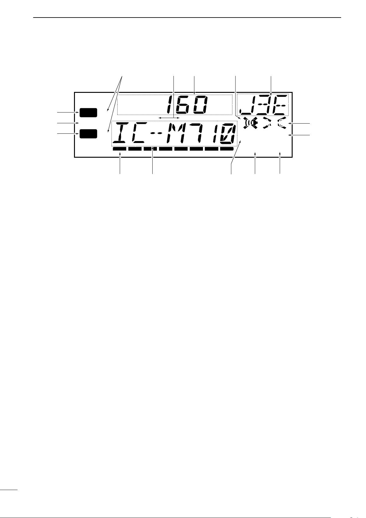
■ Display
q RECEIVE INDICATOR
Appears while receiving and when the squelch is
open.
w TUNE INDICATOR (p. 9)
Flashes while the connected antenna tuner, such
as Icom’s AT-130, is being tuned.
• Tuning starts when transmitting on a new frequency or
pushing the [TUNE] switch.
e TRANSMIT INDICATOR
➥ Appears when transmitting.
➥ Blinks when the [TX] key is pushed for transmit fre-
quency programming. (p. 12)
r S/RF METER
➥ Shows the relative received signal strength
while receiving.
➥ Shows output power while transmitting.
t CHANNEL NAME READOUT
➥ Shows the pre-programmed channel name (al-
phanumeric) during channel indication. (p. 6)
➥ Shows the transmit frequency during frequency
indication. (p. 6)
y SQUELCH INDICATOR (p. 10)
Appears when the squelch is ON.
i FUNCTION INDICATOR
Appears when the [FUNC] switch is pushed.
• Some switches activate secondary functions.
o NOISE BLANKER INDICATOR (p. 10)
Appears when the [NB] switch is turned ON.
!0 AGC OFF INDICATOR (p. 10)
Appears when the [AGC] switch is pushed to indi-
cate the AGC function is deactivated.
!1 MODE READOUT
Shows the selected operating mode (type of emis-
sion).
!2 SPEAKER OFF INDICATOR
Appears when the [SPEAKER] switch is pushed to
indicate the front panel speaker is deactivated.
!3 CHANNEL READOUT
➥ Shows the selected channel number during
channel indication. (p. 6)
➥ Shows the receive frequency during frequency
indication. (p. 6)
!4 SIMPLEX/DUPLEX INDICATORS
These appear to show whether the selected chan-
nel is simplex or duplex.
u SCAN INDICATOR (p. 7)
Appears when the scan function is in use.
• Pushing [SCAN] starts and stops the scan.
!5 FREQUENCY INDICATORS (p. 8)
Appears when the frequency entry condition is se-
lected for frequency selection.
• The [CE] key toggles the indicator ON or OFF.
5
Page 9
ITU FSK channels can be hidden using set mode. (p. 13)
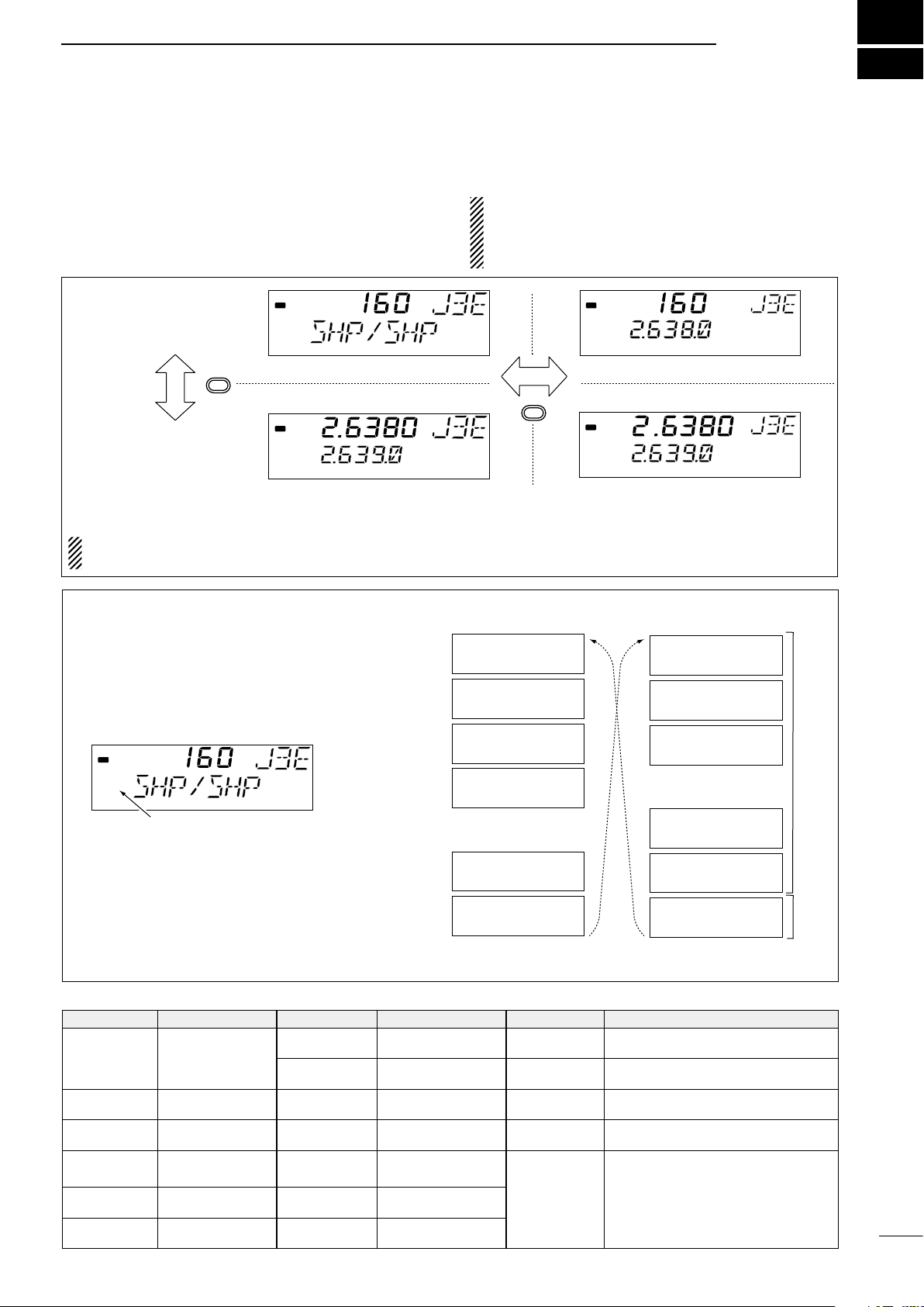
SELECTING A CHANNEL/FREQUENCY
■ Selecting a channel
3
The transceiver has 160 user channels and ITU
channels. However, the number of user channels
can be optionally restricted and ITU channels are
not available with some versions.
CHANNEL INDICATION
CH/F/REQ
FREQUENCY INDICATION
RX
RX
DUP
DUP
CHANNEL SELECTION MODE
Channel can be selected
NOTE: Channel name (alphanumeric) does not appear during
channel indication according to set mode settings (p. 14).
D Using the channel selector
[EXAMPLE]: Selection of the [GROUP] selector
The transceiver has two large controls for group selection and channel selection. The [GROUP] selector changes channels in 20 channel increments and
selects ITU channel groups*; and the [CHANNEL]
selector selects each channel.
q Be sure no “►” indicator appears on the display.
RX
►
If appears, push [CE] and then it will disappear.
DUP
w Rotate the [GROUP] selector to select the de-
sired channel group as shown at right and/or
below.
e Rotate the [CHANNEL] selector to select the de-
sired channel.
NOTE:
lected with the
lection is
When Channel 0 and/or
[2182KHz]
NOT
possible. In such a case, push
switch, channel se-
2182 kHz
is se-
[2182KHz] in advance.
RX
CE
RX
FREQUENCY SELECTION MODE
Frequency can be selected
1
WWV
21
KMI
41
WOM
61
WOO
121
FAX
141
SHP/SHP
*AII ITU channels are not available with some versions and
J3E
J3E
J3E
J3E
•
•
•
•
J3E
J3E
DUP
►
►
DUP
401
4.357.0
4 – 1
4A LTD
601
6.501.0
2501
26.145.0
25 – 1
4001
4.210.5
J3E
J3E
J3E
•
•
•
•
J3E
J3E
J3E
ITU SSB channels*
ITU FSK
channels*
CHANNEL GROUP
CHANNEL NO. DESCRIPTION CHANNEL NO. DESCRIPTION CHANNEL NO. DESCRIPTION
User channels
1 to 160
401 to 427
4 -1 to 4 - 9
601 to 608
6 - 1 to 6 - 9
801 to 832
([GROUP] selec-
tor changes in 20
channels steps)
4 MHz ITU duplex
channels
4 MHz ITU simplex
channels
6 MHz ITU duplex
channels
6 MHz ITU simplex
channels
8 MHz ITU duplex
channels
8 - 1 to 8 - 9
1201 to 1241
12 - 1 to 12 - 9
1601 to 1656
16 - 1 to 16 - 9
1801 to 1815
18 - 1 to 19 - 1
8 MHz ITU simplex
channel
12 MHz ITU duplex
channel
12 MHz ITU simplex
channels
16 MHz ITU duplex
channels
16 MHz ITU simplex
channel
18 MHz ITU duplex
channel
18 MHz ITU simplex
channels
2201 to 2253 22 MHz ITU duplex channels
22 - 1 to 22 - 9 22 MHz ITU simplex channels
2501 to 2253 25 MHz ITU duplex channels
25 - 1 to 25 - 9 25 MHz ITU simplex channel
4001 to 25040
ITU FSK duplex channels (SITOR use)
(No group separation)
6
Page 10

3
Channel scan
ch 1
ch 2 ch 3
ch 4
ch 5ch 50
scan is
cancelled
when
transmitting
Channel resume scan
ch 1
ch 2 ch 3
ch 4
ch 5ch 50
Scans pauses for
30 seconds, then
resumes after
transmitting.
Programmed scan
SELECTING A CHANNEL/FREQUENCY
D Using the keypad
Direct channel selection via the keypad is available
for quick channel selection.
q Be sure no “►” indicator appears on the display.
• If appears, push [CE] and then it will disappear.
w Enter the desired channel number via the keypad.
• A user channel is selected when channel 1160 is input (max. number may be optionally restricted).
• An ITU SSB channel is selected when channel
numbers higher than 401 are input (not available
for some versions).
• An ITU FSK channel is selected when channel
numbers higher than 4001 are input (not usable
according to set mode setting).
• The “–” key can be used 10 selecting an ITU
simplex channel.
e Push [RX] to select the entered channel.
D Using scan function
The transceiver has automatic channel or frequency
change capability (scan function). There are 3 types
of scan functions available to suit your needs.
[EXAMPLE]: Selecting channel 153.
RX
1
RX
5
RX
3
RX
RX
RX
DUP
DUP
DUP
DUP
DUP
SCAN OPERATION
q
Select your desired channel group with the [GROUP]
and [CHANNEL] selector.
• Or use the keypad and [CE] key for direct selection.
• This operation is not necessary for programme scan.
w Push [SQL] to turn OFF the squelch function if the pro-
grammed scan is selected.
e Push [FUNC] then [SQL] to start the scan.
r To stop the scan, repeat step e again.
• [CHANNEL] rotation and some other switches also
stop the scan.
ch 159
7
Scan selection is available in the set mode. See p. 14 for
scan selection.
Channel scan and channel resume scan increases channels within a 5 channel range such as ch 1 to ch 5, ch 156
to ch 160, etc. in user channels; or all channels in the group
of ITU channels.
Programmed scan changes frequencies within the frequency range between user channels 159 and 160.
ch 160
Scans the frequency range
between the programmed
frequencies on channels
159 and 160.
Scans fast when squelch
is closed and slowly when
opened.
Page 11

■ Selecting a frequency
frequency can be changed.
Select non frequency
programmed channel.
SELECTING A CHANNEL/FREQUENCY
3
The transceiver has 0.5 to 30.0 MHz general coverage receive capability, with 100 Hz resolution. The
receive frequency can be changed instantly, independent of the transmit frequency.
D Using the channel selector
q Select a channel which is programmed near the
frequency you want receive.
w Push the [CE] key to select frequency selection
mode.
•
“►” appears on the display.
e Rotate the [CHANNEL] selector to change the fre-
quency.
r To return to the previous frequency push [CE].
• “►” disappears and the previous frequency or channel
name appears.
NOTE: The selected frequency is used for temporary receiving (transmitting is not available). This
frequency is cleared once the channel is changed.
If you want to program a frequency refer to p. 12,
memory programming.
RX
CE
No “►” indicator shows that the channel
will be changed when rotating [CHANNEL].
RX
►
“►” and the frequency show that the
DUP
DUP
D Using the keypad
CAUTION: A frequency can be entered into a user
channel or ITU simplex channelby pushing the
[RX] key. However, when pushing and holding the
[RX] key after entering a frequency. The previousty
programmed contents are erased and cannot be
retrieved. Therefore, keypad entry should be used
only on spare channels.
q Select the memory channel to be used for general
coverage use.
w Push [CE] to select frequency selection mode.
• “►” appears on the display.
e Enter the desired frequency with 5 or 6 digits.
r Push [RX] to input the frequency.
• Do not hold [RX] for more than 0.5 seconds,
otherwise the frequency will be programmed into
the channel.
[EXAMPLE]: Setting 12.3450 MHz
CE
►
1
►
23
45
►
0
RX
(momentarily)
RX
►
RX
►
After temporarily receiving.
CE
8
Page 12

4
microphone
connector
[SQL]
[SPEAKER] [CLARITY]
TX FREQ
■
Basic voice receive and transmit
RECEIVE AND TRANSMIT
q Check the following in advance:
➥ The microphone is connected.
➥ The [SPEAKER] switch is turned OFF.
➥ The [SQL] switch is turned OFF.
➥ The [CLARITY] control is set to the center posi-
tion.
➥ The memory mode is selected.
• If necessary, push [CH/FREQ] to select the memory
mode.
■ Functions for transmit
w Select the desired channel to be received with the
[GROUP] and [CHANNEL] selectors.
• When receiving a signal, the S-meter shows the signal
strength.
e Adjust [VOLUME] to the desired audio level when
receiving a signal.
r If the received signal is in a different mode, push
[MODE] to select the desired operating mode.
t If connected, push [TUNE] to tune the antenna
tuner.
• This operation is not necessary when “automatic tuning” is selected in the set mode (p. 13).
y To transmit on the channel, push and hold the PTT
switch on the microphone.
• “TUNE” flashes for 1 to 2 seconds for the first transmission on a channel when an antenna tuner is connected.
u After the flashing stops, speak into the microphone
at your normal voice level.
• The RF meter shows the output power, according to
your voice level.
i Release the PTT switch to return to receive.
9
D Transmit frequency check
When “DUP” appears on the display, such as for a
ship-to-shore channel, the transmit frequency differs
from the receive frequency.
In such cases, the transmit frequency should be monitored before transmitting to prevent interference to
other stations.
D Transmit power selection
The transceiver has 3 selectable output powers.
High power allows longer distance communications
and low power reduces power consumption.
NOTE: Low power setting affects all channels except the 2182 kHz emergency channel.
Push and hold [TX FREQ] to monitor the transmit frequency.
• The display shows the transmit frequency.
q Push [FUNC] then [TX] to call up the following dis-
play.
w Rotate the [CHANNEL] selector to select high or
low output power.
3 : high power (150 W PEP)
2 : middle power (60 W PEP)
1 : low power (20 W PEP)
e Push [FUNC] or [CE] to return to the previous dis-
play.
Page 13

■ Functions for receive
[CLARITY]
“SQL” appears when the squelch function is ON (noise is muted).
RX
DUP
►
D Squelch function
The squelch function detects signals with voice components and squelches (mutes) unwanted signals,
such as unmodulated beat signals. This provides
quiet standby.
When you need to receive weak signals, the squelch
should be turned OFF.
D Noise blanker
The noise blanker function reduces pulse type noise,
such as that coming from engine ignitions.
The noise blanker may distort reception of strong
signals. In such cases, the noise blanker should be
turned OFF.
RECEIVE AND TRANSMIT
• Push [SQL] to toggle the function ON or OFF.
DUP
• Push [NB] to toggle the function ON or OFF.
RX
DUP
“NB” appears when the noise blanker is ON.
SQL
NB
4
D AGC OFF function
The receiver gain is automatically adjusted according to the received signal strength with the AGC (Automatic Gain Control) function, to prevent distortion
from strong signals and to obtain a constant output
level.
When receiving weak signals with adjacent strong
signals or noise, the AGC function may reduce the
sensitivity. In this situation, the AGC function should
be deactivated.
D RF gain setting
The receiver gain can be reduced with the RF gain
setting. This may help to remove undesired weak signals while monitoring strong signals.
Usually the AGC function reduces the RF gain according to the receive signal strength and these weak
signals are removed. However, during periods of no
signals, these weak signals may not be heard.
In such cases, the RF gain may be useful for setting
a minimum level at which to hear signals.
• Push [AGC] to toggle the function ON or OFF.
RX
Appears when the [AGC] switch is ON
(AGC function deactivates).
AGCAGC
q Push [FUNC] then [RX] to call up the following dis-
play.
w Rotate the [CHANNEL] selector to set the desired
minimum cutting level.
• “0” to “9” are available.
• S-meter shows the minimum permited level.
e Push [FUNC] or [CE] to exit the RF gain display.
D Clarity control
Voice signals received from other stations may be
difficult to receive. This may sometimes happen if a
station is transmitting slightly off frequency. In such
cases, vary the receive frequency only, using the
[CLARITY] control.
• Adjust [CLARITY] to improve the audio signal.
10
Page 14

4
2
8
4
5
1
3
6
7
ACC(1) socket
pin 1
pin 2
CW key
2
8
4
5
1
3
6
7
ACC(1) socket
FSK terminal unit
FSK keying
AF input
Tx/Rx control
Ground
pin 3
pin 4
pins 2, 5
RECEIVE AND TRANSMIT
■ CW operation (Depends on versions)
The transceiver has the following CW keying features
CW key connection
selectable in the set mode, as described on page
15.
➥ Full break-in (receiving is possible while transmitting)
➥ Semi break-in (automatic transmission with keying)
➥ OFF (manual transmission is necessary before keying)
q Connect a CW keyer or an external electronic
keyer to the ACC(1) socket, as shown at right.
w Select the desired channel to operate in the A1A
(CW) mode.
e When the selected channel is not in the A1A (CW)
mode, push [MODE] one or more times to select
“A1A.”
r Operate the CW keyer to transmit a A1A (CW) sig-
nal.
NOTE:
• A1A mode is not available in some versions.
• CW narrow can be selected in the set mode when
an optional filter is installed. (p. 14)
■ FSK operation (Depends on versions)
The transceiver has FSK and J2B modes for FSK operation—use FSK when using the built-in oscillator;
use J2B when using an AFSK terminal unit.
q Connect an FSK terminal unit as shown at right.
w Select the desired channel.
• FSK ITU channel group, ch 4001 to ch 25040, are
available, depending on the version.
e Push [MODE] one or more times to select either
“FSK” or “J2B.”
r Operate the FSK terminal unit.
NOTE:
• FSK shift frequency and FSK polarity can be ad-
justed in the set mode (pgs. 14 and 15).
• Some transceivers may operate 1.7 kHz higher
than the IC-M710’s J2B mode, even when the
same displayed frequencies are in use.
FSK terminal unit connection
11
Page 15

USER CHANNEL PROGRAMMING
RX
DUP
Push and hold [RX]
►
■
Programming a frequency
5
The IC-M710 has up to 160 user-programmable
channels each with channel name capability of up to
7 alphanumeric characters.
D Receive Frequency
q Select the desired user channel to be pro-
grammed.
•
Channel 1 to 160 (maximum) are programmable.
w Push the [CE] key to select frequency selection
mode.
• “►” and a frequency appear on the display.
e Enter the desired frequency via the keypad with 5
or 6 digits.
• Or rotate the [CHANNEL] selector to change the frequency.
r To change the operating mode (type of emission),
push [MODE] one or more times.
t Push and hold [RX] for 1 second to program the
user channel.
D Transmit frequency
q
Select the desired user channel to be programmed.
w Push [TX].
• “$” blinks.
e Push [CE] to select frequency selection mode.
• “►” and frequency appear on the display.
r Enter the desired frequency via the keypad with 5
or 6 digits.
• The [CHANNEL] selector cannot be used.
• Refer to p. 24 for programmable frequency range (frequency coverage transmit).
t Push and hold [TX] for 1 second to program.
y Push [TX] to clear the
“$” blinking.
NOTE: ITU simplex channels can be programmed
as well as user channels. However, transmit frequencies cannnot be programmed (not necessary
to program).
Push [CE]
Set the frequency
Push [TX]
Push [CE]
Push and hold [RX]
after entering a
frequency.
RX
“►” and frequency appear.
RX
Use keypad or channel selector.
RX
Programming is completed.
RX
TX
TX
“T ” blinks.
RX
TX
RX
TX
DUP
►
DUP
►
DUP
DUP
DUP
►
DUP
D Channel name
q Select the desired user channel to be pro-
grammed.
w Push [CH/FREQ] to select channel indication.
e Push [FUNC] and then [CE].
• The channel name (alphanumeric) readout blinks.
r Rotate the [GROUP] selector to cursor position
and the [CHANNEL] selector for the message contents.
• To return to the previous message, push [CE].
t Push and hold [RX] to program the message.
• Blinking stops.
• Available characters
RX
Push [FUNC]
then [CE]
Rotate [GROUP]
and [CHANNEL]
to select cursor
and character
Push [RX]
to
to
(space)
RX
RX
DUP
DUP
DUP
12
Page 16

6
[POWER]
Status
Item
[1]
[FUNC]
AT-130
(default)
AT-120
AH-3
Tuning starts when
pushing [PTT] on a new
frequency.
Tuning starts only when
[TUNER] is pushed.
(default)
FSK channels do not appear
SET MODE
■ Set mode operation
Set mode operation is used for programming infrequently changed values or functions.
The IC-M710 has up to 13 items.
NOTE: Some of the set mode items described in
this section are not available on some transceiver
versions.
q Push [POWER] to turn power OFF.
w While pushing and holding [FUNC] and [1], turn
power ON and enter the set mode.
• The set mode is selected and one of its items appears.
e Rotate the [GROUP] selector to select the de-
sired item.
r Rotate the [CHANNEL] selector to set the values
or options for the selected item.
t Turn power OFF and then ON again to exit the
set mode.
■ Set mode contents
(1) FSK ITU channels
FSK ITU channels appear as a group between the
ITU 25 MHz band and user channels. This FSK channel group can be hidden for voice communication use
only.
(2) Connected antenna tuner
The transceiver has several tuner control systems
for use with an optional Icom antenna tuner. Select
the condition depending on the connected antenna
tuner.
Note that internal switch selection may be required
when using a non-Icom tuner (p. 20).
(no SITOR operation).
(default)
FSK channels appear
(SITOR operation).
13
(3) Automatic tuning operation
When the optional AT-130
connected, tuning can be started automatically without the [TUNE] switch for instant operation.
If manual tuning is required, this automatic operation
can be deactivated.
AUTOMATIC ANTENNA TUNER is
Page 17

Frequency shift:
170 Hz
(default)
Frequency shift:
425 Hz
Frequency shift:
850 Hz
Fastest scan speed
Slowest scan speed
(default: 4)
(4) Scan type selection
Passband:
2.3 kHz/−6 dB
(default)
Passband:
500 Hz/−6 dB
Channel scan
Scan is canceled when
transmitting. (default)
Channel resume scan
Scan pauses when squelch
opens, then resumes after
30 seconds.
Programmed scan
Scan operates over the
frequency range.
This item selects one of the following scan functions.
Channel scan and channel resume scan search 5
channels around a user selected channel or search
all ITU channels in the band when an ITU channel is
selected.
Programmed scan searches signals within the frequency range and activates slowly while squelch is
open and fast while squelch is closed.
(5) Scan speed
Selects scan speed as follows:
(unit: msec./ch)
Selection
Channel Scan
Channel resume
scan (sec./ch)
Programmed scan
(squelch open*)
Faster Slower
*squelch closed: 10 ms/ch
1 2 3 4 5 6 7 8 9 10
130 260 520 1040 2080 4160 8320 16360 33280 66560
1 2 3 4 5 6 7 8 9 10
10 20 40 60 90 140 210 320 480 720
SET MODE
6
(6) Channel name and frequency
The lower half of the display can be set to display a
programmable channel name or a receive frequency
according to an operator’s needs.
(7) CW/FSK narrow filter
This selects the passband width for A1A (CW), FSK
or J2B mode.
NOTE: When “on” is selected without the optional
filter installed, general version does not function
on these modes.
(8) FSK frequency shift
Several shift settings (the difference between the
mark and space frequency) are used for FSK operation. This item allows you to select a shift setting for
almost any FSK system.
Channel number
and channel name
(alphanumeric)
(default)
Channel number
and frequency
14
Page 18
6
Lowest contrast
Highest contrast
(default: 7)
NMEA ID: 1
(default)
NMEA ID: 99
[DSC] (or REMOTE
according to the version)
socket (default)
The [CLONE] jack
FSK normal
(default)
FSK reverse
Full break-in
Automatic keying without
delay time (default)
Semi break-in
Automatic keying with delay
time
OFF
Manual transmission
necessary for keying
SET MODE
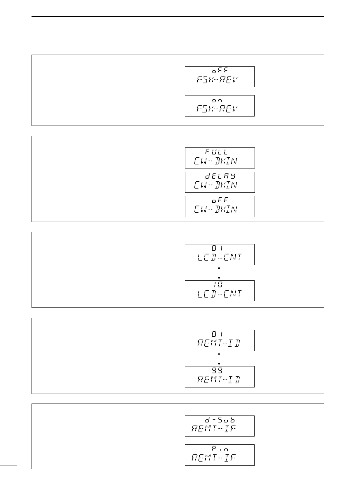
(9) FSK polarity
Normal and reverse polarities are available for FSK
operation. This item allows you to select one of these
polarities.
“FSK-REV oFF” (normal):
key open (mark); key close (space)
“FSK-REV on” (reverse):
key open (space); key close (mark)
(10) CW break-in
CW break-in function (in A1A (CW) mode) toggles
transmit and receive with CW keying. Full break-in allows you to receive signals between transmitted keying pulses during CW transmission. Semi break-in
allows you to mute receiving until keying stops with
some delay time.
(11) LCD contrast
The LCD contrast can be adjusted through 10 levels,
to suit transceiver mounting angle, location and ambient lighting.
(12) ID number setting for remote control
When connecting an external controller, such as a
personal computer, 2-digit ID codes are required
to access the transceiver. The IC-M710 adopts the
NMEA0183 format, and uses a “proprietary sentence”
for remote control.
15
(13) Remote control input terminal
Remote control signals can be input via the [DSC] (or
REMOTE) socket or [CLONE] jack.
Page 19
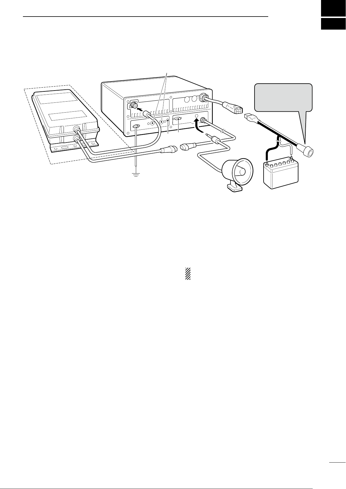
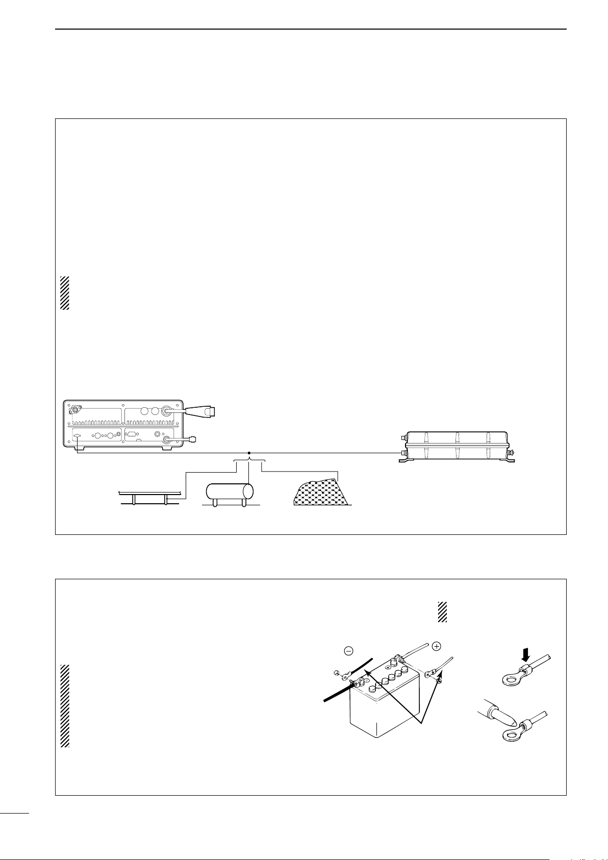
CONNECTIONS AND INSTALLATION
Optional AT-130
External
speaker
q
w
r
t
y
u
i
e
12 V battery
R CAUTION:
NEVER remove the
line fuse from the DC
power cable.
■ Connections on the rear panel
7
q ANTENNA CONNECTOR (p. 20)
Connects a 50 ø HF band antenna with a 50 ø
matched coaxial cable and a PL-259 plug.
w GROUND TERMINAL
IMPORTANT! Connects to a ship’s (or vehicle’s)
ground. See p. 19 for details.
e ACC(1) and ACC(2) SOCKETS
See p. 17 for details.
r CLONE JACK
For Dealer use only.
t REMOTE SOCKET (p. 18)
REMOTE socket for General version.
y EXTERNAL SPEAKER JACK
Connects a 4 to 8 ø external speaker using a
monaural plug. This external audio is not muted by
the [SPEAKER] switch on the front panel.
1
⁄4”
■ Unpacking
Microphone (HM-180) ············································· 1
Microphone hanger ················································· 1
DC power cable (OPC-1107A) ······························· 1
Mounting bracket ···················································· 1
Bracket knobs ························································· 4
Flat washers (M5) ··················································· 4
CONNECTORS
DIN connector (8-pin for ACC1) ······························ 1
DIN connector (7-pin for ACC2) ······························ 1
Speaker plug ·························································· 1
Tuner connector ······················································ 1
Pins for tuner connector ········································· 4
Plates for tuner connector ······································ 4
u TUNER RECEPTACLE
Connects a control cable to an optional AT-130 an-
tenna tuner. A female connector is supplied for
connection.
i DC POWER RECEPTACLE
Connects to a regulated 12–16 V DC power source
such as a 12 V battery or DC power supply using
the supplied DC power cable.
CAUTION: DO NOT connect to a 24 V bat-
tery. This will damage the transceiver.
NUTS AND BOLTS
Allen bolt (M6 × 50) ················································ 4
Self-tapping screws (M6 × 30) ································ 4
Nuts (M6; use 2 pcs. for each bolt) ························ 8
Flat washers (M6) ··················································· 8
Spring washers (M6) ·············································· 4
Self- tapping screws
(M3 × 16 for mic. hanger) ································ 2
FUSES
DC power cable (30 A) ··········································· 1
1205 (internal) ························································ 2
16
Page 20
7
CONNECTIONS AND INSTALLATION
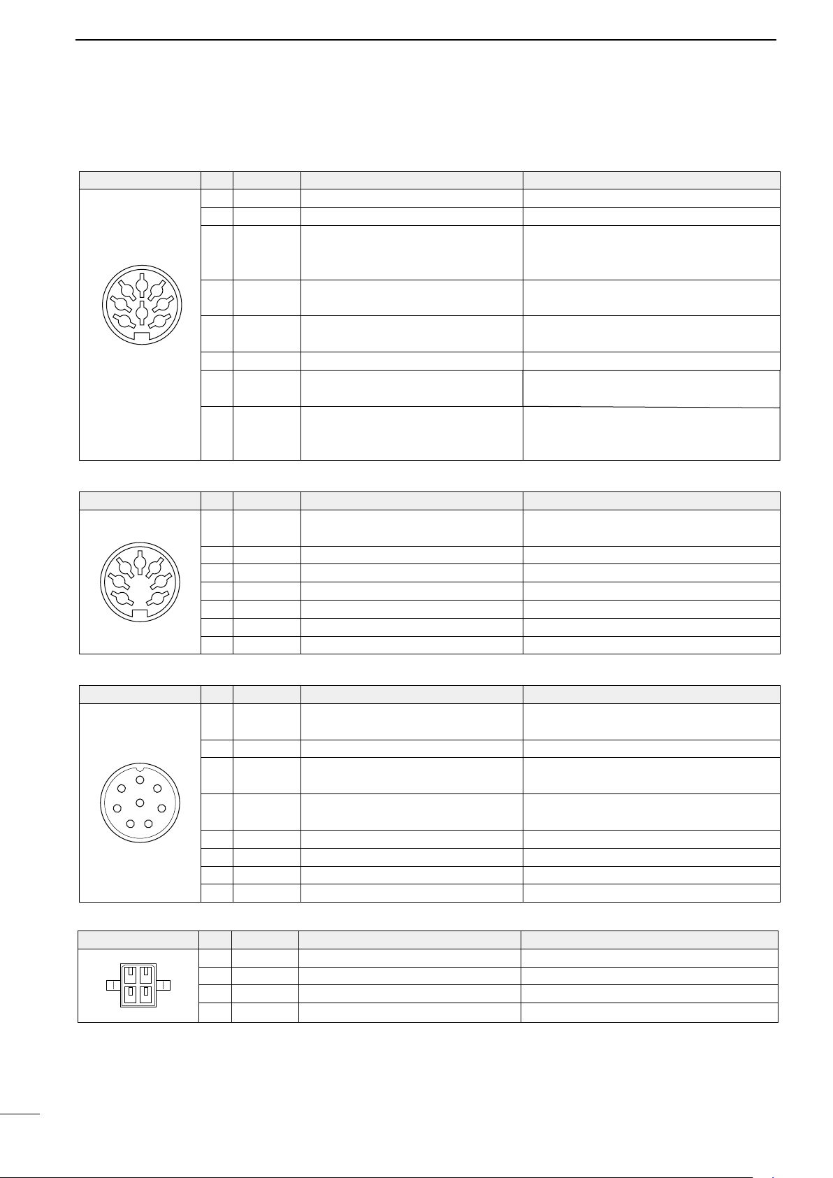
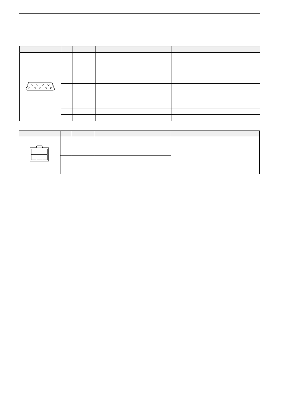
■ Connector information
ACC(1)
2
45
13
8
67
Rear panel
view
ACC(2)
2
45
13
67
Rear panel
view
PIN NAME DESCRIPTION
PIN
SPECIFICATIONS
1 CWK CW and FSK keying input. Input level: Less than 0.6 V for transmit.
2 GND Connects to ground. Connected in parallel with ACC(2) pin 2.
Input/output pin.
3 SEND
Goes to ground when transmitting.
When grounded, transmits.
4 MOD
5 AF
Modulator input.
Usable when pin 3 is grounded.
AF detector output.
Fixed, regardless of the [AF] position.
6 SCAN Starts scan when grounded.
7 13.6 V 13.6 V output when power is ON.
Ground level: –0.5 to 0.8 V
Input current: Less than 20 mA
Connected in parallel with ACC(2) pin 3.
Input impedance: 10 kø
Input level: Approx. 100 mV rms
Output impedance: 4.7 kø
Output level: 100–300 mV rms
Scan operation: Less than 0.6 V
Output current: Max. 1 A
Connected in parallel with ACC(2) pin 7.
Control voltage: –3 to 0 V
8 ALC ALC voltage input.
Input impedance: More than 10 kø
Connected in parallel with ACC(2) pin 5.
PIN NAME DESCRIPTION
PIN
1 8 V Regulated 8 V output.
Output voltage: 8 V ±0.3 V
Output current: Less than 10 mA
SPECIFICATIONS
2 GND Same as ACC(1) pin 2.
3 SEND Same as ACC(1) pin 3.
4 NC No connection.
5 ALC Same as ACC(1) pin 8.
6 RLC T/R relay control output. When transmitting: 0 V (less than 0.5 A)
7 13.6 V Same as ACC(1) pin 7.
MICROPHONE PIN NAME DESCRIPTION
PIN
1 MIC+
Audio input from the microphone
element.
2 NC No connection.
1
2
3
7
8
6
54
3 AF1
4 AF2
AF output controlled with [VOLUME].
Connected to pin 4 in the microphone.
AF input.
Connected to pin 3 in the microphone.
5 PTT PTT switch input. When grounded, transmits.
6 GND Connected to ground.
7 MIC– Coaxial ground for MIC+.
8 AF– Coaxial ground for AF1 and AF2.
TUNER PIN NAME DESCRIPTION
12
PIN
1 KEY Key signal input.
2 START Start signal output.
3 13.6V 13.6 V output
34
4
E
_ terminal
SPECIFICATIONS
Input impedance: 600 ø
Output impedance: 4 ø
SPECIFICATIONS
–0.5 to 0.8 V during tuning
Pulled up 8 V, 0 V (100 msec.) as start signal.
Max. current :2 A
Ground
17
Page 21
REMOTE
69
51
CONNECTIONS AND INSTALLATION
PIN NAME DESCRIPTION
PIN
1 MOD+
2 MOD– Coaxial ground for MOD+.
3 AF+
4 AF– Coaxial ground for AF+.
5 NMI+ NMEA data input. NMEA standard format/level
6 NMI– Coaxial ground for NMI+.
7 NMO+ NMEA data output. NMEA standard format/level
8 NMO– Coaxial ground for NMO+.
9 GND Ground for digital equipment.
Modulation input from an external
terminal unit.
AF detector output for an external
terminal unit.
Input impedance: 600 ø
Input level: Approx. 100 mV rms
Output impedance: 600 ø
Output level: 0.25–2.5 V rms
SPECIFICATIONS
6
DC 13.6V PIN NAME DESCRIPTION
1 2
4 635
PIN
1–3 + + DC input
4–6
– _ DC input
SPECIFICATIONS
Max. power consumption: 30 A
18
Page 22
7
Crimp
Solder
or
Supplied
DC power cable
red
black
12 V
battery
Optional AT-130
Transceiver
Copper pipe Metal object Copper screen
CONNECTIONS AND INSTALLATION
■ Ground connection
The transceiver and antenna tuner MUST have an
adequate ground connection. Otherwise, the overall
efficiency of the transceiver and antenna tuner installation will be reduced. Electrolysis, electrical shocks
and interference from other equipment could also
occur.
For best results, use the heaviest gauge wire or strap
available and make the connection as short as possible. Ground the transceiver and antenna tuner to one
ground point, otherwise voltage differences between
2 ground points may cause electrolysis.
CAUTION:
The IC-M710 has a negative ground.
NEVER connect the IC-M710 to a “positive ground
ship,” otherwise the transceiver will not function.
Ground system example
Good ground points
• Ship’s ground terminal
• External ground plate
• External copper screen
Acceptable ground points
• Stainless steel tuna tower
• Stainless steel stanchion
• Through mast
• Through hull
• Metal water tank
Undesirable ground points
(these points may cause electrolysis)
• Engine block
• Keel bolt
Unusable ground points
( these connections may cause an explosion or elec-
trical shock)
• Gas or electrical pipe
• Fuel tank
• Oil-catch pan
19
■ Power source
The transceiver requires regulated DC power of
13.6 V and at least 30 A. There are 3 ways to supply power:
• A direct connection to a 12 V battery in your ship,
through the supplied DC power cable.
CAUTION: The supplied DC power cable MUST
be used to provide power to the transceiver.
AVOID exceeding the 3 m (10 ft) length of the DC
power cable. If it is necessary to make a run of
over 3 m (10 ft), use a #6 or similar gauge wire instead of the supplied DC power cable, for a maximum run of 6 m (20 ft).
DC power cable connection
NOTE: Use terminals for
the cable connection.
Page 23
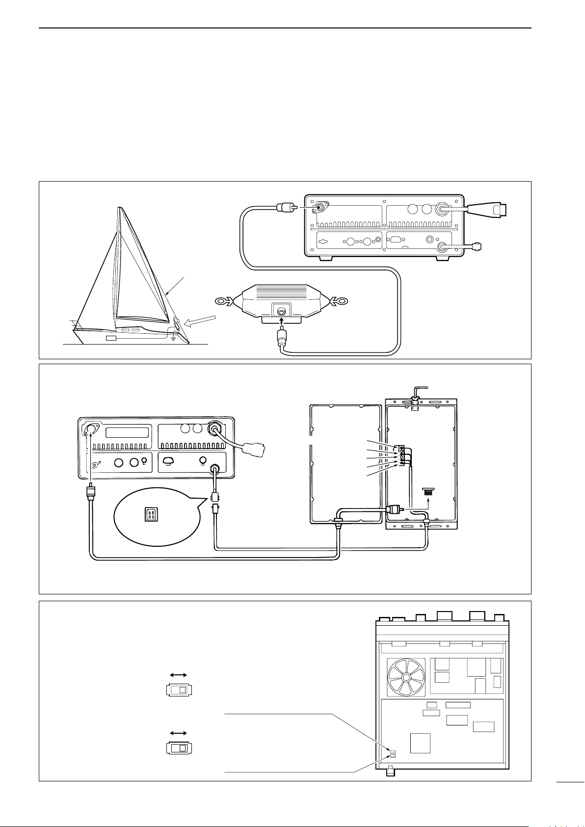
■ Antenna
Coaxial cable
To antenna element
Control cable (sold separately)
An optional OPC-566 is available
IC-M710
[13.6]
[E] (AT-130 only*)
[START]
[KEY]
[E]
[KEY]
[13.6]
[START]
AT-130
[GND]
*For the AT-130, the [GND] terminal can be used inside of the [E] terminal.
S9
(Start port level)
S11
(Key port input)
CONNECTIONS AND INSTALLATION
7
Most stations operate with a whip or long wire (insulated backstay) antenna. However, these antennas
cannot be connected directly to the transceiver, since
their impedance may not be matched with the transceiver antenna connector.
D MN-100/MN-100L ANTENNA MATCHERS
Antenna wire
MN-100/MN-100L
D AT-130 AUTOMATIC ANTENNA TUNER
Even with a 50 ø matched antenna, all marine bands
may not be fully usable. The following antenna
matcher, or antenna tuner may be helpful for proper
antenna installation.
D Non-Icom tuner
Some non-Icom tuners may be used with the ICM710. Please consult your dealer or marina if you
wish to use one. The following internal settings may
be required for connection.
Supplies 8 V when pushing
[TUNE].
Accepts “LOW” as an answer back signal.
Grounded when pushing [TUNE].
(used for AT-130—default)
Accepts “HIGH” as an answer back signal.
(used for AT-130—default)
20
Page 24
7
Spring washer
Flat
washers
Nuts
(Use two nuts to
prevent loosening.)
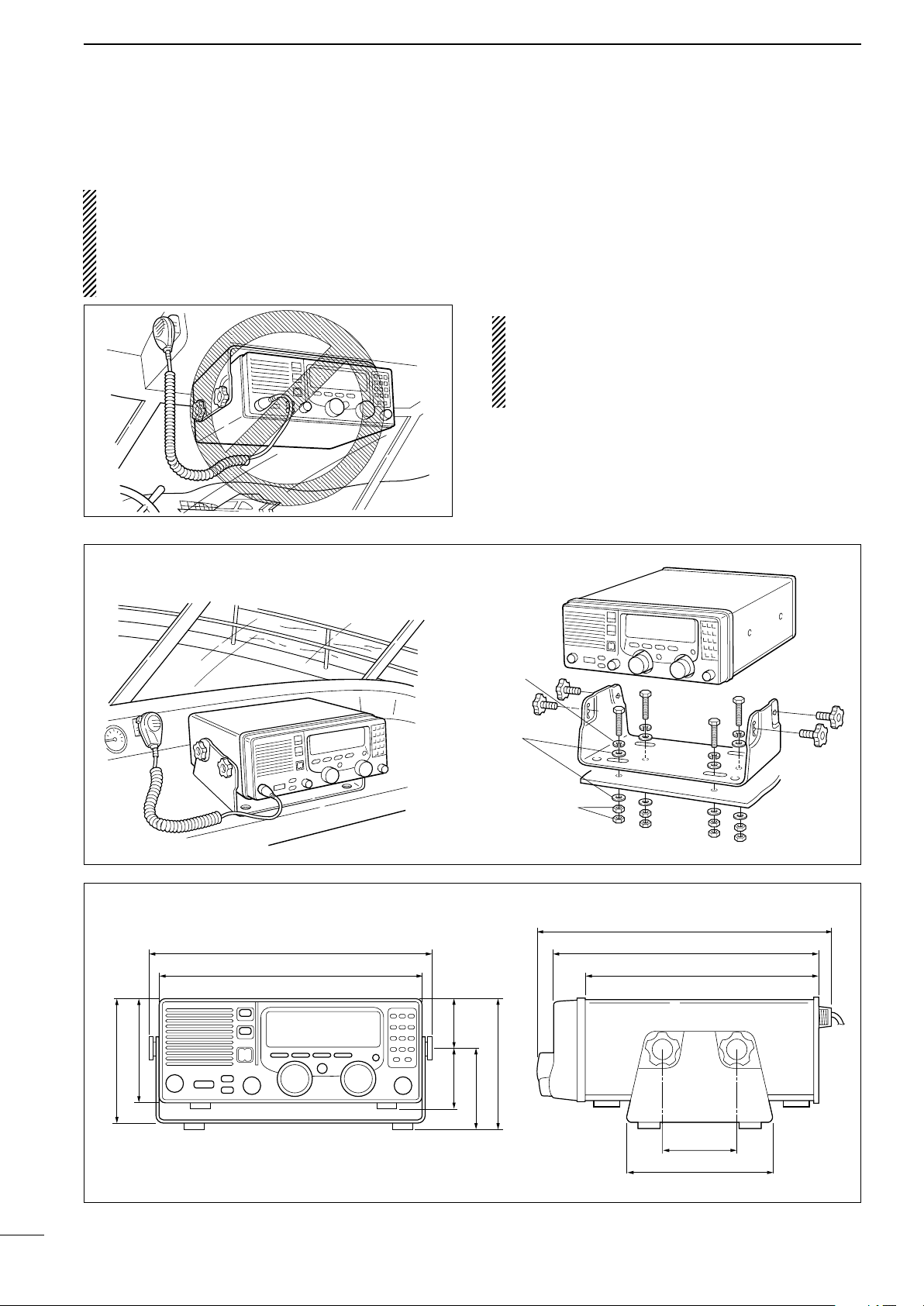
115
(4
1
/
2
)
67
(2
5
/
8
)
93.5
(3
11
/
16
)
100 (3
15
/
16
)
152
(6)
58
(2
9
/
32
)
290
(11
7
/
16
) 280 (11)
312.5 (12
5
/
16
)
350 (13
25
/
32
)
319 (12
9
/
16
)
143
(5
5
/
8
)
170 (6
11
/
16
)
Unit:mm(inches)
CONNECTIONS AND INSTALLATION
■ Mounting
R
WARNING: NEVER mount the transceiver
overhead. The weight of the transceiver is approximately 7.8 kg
(17.4 lb)
, but its apparent weight will
increase several fold due to wave shocks or vibration. The transceiver must be mounted on a flat,
hard surface.
D Mounting example
D Mounting location
Select a location that provides easy access to the
front panel for navigation safety, has good ventilation
and is not subject to sea spray. The face of the transceiver should be at 90 degrees to your line of sight
when operating it.
CAUTION: KEEP the transceiver and microphone
at least 1 meter away from your vessel’s magnetic
navigation compass.
Check the installation angle; the display may not
be easy to read at some angles.
21
D Transceiver dimensions
Page 25
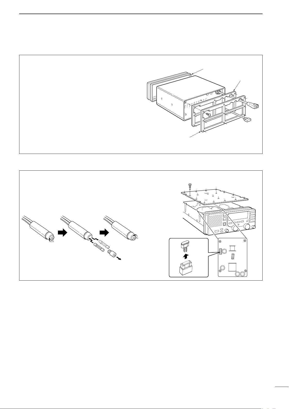
■ Disassembling the transceiver
Rear frame
Rear sealing
Front sealing
D Opening the case
Follow the case and cover opening procedures
shown here when you want to adjust a setting for
non-Icom tuner control.
q Remove the 9 screws from the rear panel, then re-
move the rear frame and rear sealing.
w Remove the transceiver case.
e When reassembling the transceiver, check the fol-
lowing points:
➥ Internal fan and slits in the case are on the
same side.
➥ Front sealing is mated correctly.
➥
Rear sealing is attached in the proper orientation.
➥ Screws are tightened securely.
CONNECTIONS AND INSTALLATION
7
■ Fuse replacement
The fuses are installed in the DC power cable and
the circuitry in the body, to protect the transceiver.
D DC power cable fuse
FGB 30 A
D Circuitry fuse
5 A
22
Page 26

8
TROUBLESHOOTING
What appears to be equipment malfunction may not
be damaging or difficult to solve. Check the following
chart before making any adjustments or sending the
transceiver to an Icom Service Center.
PROBLEM POSSIBLE CAUSE SOLUTION REF.
Power does not come
ON when [POWER] is
pushed.
• Power cable is improperly connected.
• The DC power cable fuse or circuitry fuse
is blown.
POWER
• Reconnect the cable securely.
• Find and repair the cause of the problem
and then replace the damaged fuse with
a new one.
p. 16
p. 22
No sound comes from the
speaker.
Sensitivity is too low and
only strong signals are audible.
RECEIVETRANSMIT
The received audio is unclear or distorted.
Your signal does not reach
as far away as usual.
• The [SPEAKER] switch is turned OFF.
• Microphone is not connected.
• RF gain is set too deeply and several
segments of the S-meter appear.
• The squelch is closed.
• Antenna is not properly matched to the
operating frequency.
• RF gain is set too deeply.
• Wrong tuner condition is selected in the
set mode.
• Wrong operating mode is selected.
• AGC is deactivated while receiving a
strong signal.
• Noise blanker is turned ON when receiving a strong signal.
• The [CLARITY] control is rotated too far
clockwise or counterclockwise.
• The transmit power is set low.
• The antenna tuner is improperly matched
to the operating frequency when manual
tuning is selected.
• Turn ON the [SPEAKER] switch.
• Connect the microphone to the [MICROPHONE] connector.
• Push [FUNC], then [RX] to reset the RF
gain. (RF GAIN 9 applies audio.)
• Adjust the squelch to proper level or push
[SQL] to turn it OFF to receive weak signals.
• Push [TUNE] to tune the using antenna
tuner or select “automatic tuning” in the
set mode when using an optional AT-
130.
• Push [FUNC], then [RX] to reset the RF
gain.
• Set the proper tuner for the connected
tuner.
• Push [MODE] to select the proper operating mode.
• Push [AGC] to activate the AGC function.
• Push [NB] to turn the noise blanker OFF.
• Adjust the [CLARITY] control to receive
proper audio output.
• Push [FUNC], then [TX] to reset the
transmit power. (RF-PWR 3 is maximum
power.)
• Push [TUNE] to tune the using antenna
tuner, or select “automatic tuning” in the
set mode.
p. 2
p. 2
p. 10
p. 10
p. 13
p. 10
p. 13
p. 9
p. 10
p. 10
p. 10
p. 9
p. 9
or
p. 13
23
Transmit signal is unclear
or distorted.
No contact is possible with
another station.
Frequency cannot be set
via the keypad.
All indicators appear
and the channel number
DISPLAY
cannnot be read.
FSK ITU channels cannot
be selected.
• CW or FSK mode is selected for voice
transmission.
• The wrong operation mode is selected.
• Microphone is too close to your mouth.
• Wrong transmit frequency is set. • Push [TX FREQ] to check and store the
• The [CE] key is not pushed (“►” does not
appear) before digit entry.
• 2182 kHz is selected with the [2182KHz]
switch.
• The highest contrast is selected in the set
mode.
• SITOR operation is set to OFF in the set
mode.
• Push [MODE] to select USB mode (or
AM, R3E, etc.).
• Push [MODE] to select the proper operating mode.
• Speak into the microphone naturally and
do not hold the microphone too close to
your mouth.
correct transmit frequency.
• Push [CE] (“►” appears), then enter the
desired frequency.
• Push [2182KHz], then set the frequency.
• Set to the proper display contrast. p. 15
• Set “SITOR” to ON in the set mode. p. 13
p. 9
p. 9
–
p. 9
p. 8
p. 6
Page 27
■ Specifications
SPECIFICATIONS AND OPTIONS
9
D GENERAL
• Frequency coverage:
Receive 500 kHz–29.999 MHz
Transmit 1.6– 2.9999 MHz 4.0– 4.9999 MHz
6.0– 6.9999 MHz 8.0– 8.9000 MHz
12.0– 13.9999 MHz 16.0– 17.9999 MHz
18.0– 19.9999 MHz 22.0– 22.9999 MHz
25.0– 27.5000 MHz
• Mode
: J3E(USB), H3E, J2B(AFSK),
F1B(FSK), R3E, A1A(CW)
( available modes differ with the
version)
• Number of channels :1136 (max.)
160 (user programmable)
662 (ITU FSK duplex)
• Antenna impedance : 50 ø nominal
• Usable temp. range :
• Frequency stability : ±10 Hz
( ±20 Hz above 15 MHz for General
• Power supply requirement : 13.6 V DC±15%
• Current drain :
:
• Dimensions : 2
(projections not included) : 11.3(W)×4.4(H)×12.8(D) in
• Weight (approx.) : 7.8 kg; 17.4 lb
242 (ITU SSB duplex), 72 (ITU SSB
simplex)
–30°C to +60°C (–22°F to +140°F)
(–30°C to +60°C; –22°F to +140°F)
version)
T
ransmit (max. output power) 30 A
Receive (max. audio output) 2.5 A
91.4(W)×116.4(H)×315(D) mm
D TRANSMITTER
• Output power : 150, 60, 20 W pep (se-
lectable)
( 60, 20 W only for 25 MHz
band)
• Spurious emissions : –65 dB typical
• Carrier suppression : 40 dB typical
• Unwanted sideband suppression: 55 dB typical
• Microphone impedance : 600 ø
D RECEIVER
• Sensitivity
J3E, R3E, J2B, F1B, A1A : 0.5 µV
(for 12 dB SINAD) 1.0 µV (1.6–1.7999 MHz)
6.3 µV (0.5–1.5999 MHz)
H3E (for 10 dB S/N) : 3.2 µV (1.8–29.9999 MHz)
•
Spurious response rejection :
(1.6–29.9999 MHz)
• Audio output power : 4.0 W
( at 10% distortion with a
4 ø load)
• Audio impedance : 4 ø
(4 to 8 ø acceptable)
• Clarity variable range : ±150 Hz
All stated specifications
notice or obligation.
are subject to change without
(1.8–29.9999 MHz)
6.3 µV (1.6–1.7999 MHz)
32 µV (0.5–1.5999 MHz)
70 dB typical
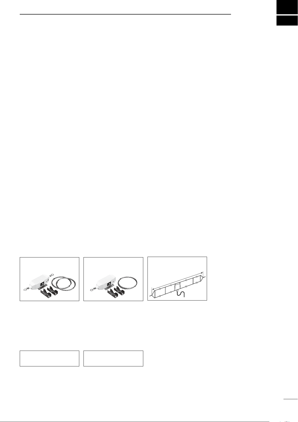
■ Options
MN-100
antenna matcher
Matches the transceiver to a
dipole antenna. Covers all HF
bands from 1.5 to 30 MHz.
8 m (26 ft.) × 2 antenna wires
are included.
AT-130
antenna matcher
Matches the transceiver to a
long wire antenna with a minimum of insertion loss.
MN-100L
antenna matcher
Matches the transceiver to a
long wire antenna. Covers all
HF bands from 1.5 to 30 MHz.
15 m (49 ft.) × 1 antenna wire
are included.
OPC-566
control cable
The optional control cable for
AT-130.
AH-710
folded dipole antenna
approx. 24.5 m; 80.3 ft
Covers from 1.9 to 30 MHz
band. Has an SO-239 connec
tor. Easy to assemble (nonkink construction).
-
Approved Icom optional equipment is designed for
optimal performance when used with an Icom transceiver.
Icom is not responsible for the destruction or damage to an Icom transceiver in the event the Icom
transceiver is used with equipment that is not manufactured or approved by Icom.
24
Page 28

A5483H-1EX-6a
Printed in Japan
© 1997–2017 Icom Inc.
1-1-32 Kamiminami, Hirano-ku, Osaka 547-0003 Japan
 Loading...