

Page 1
INSTRUCTION MANUAL
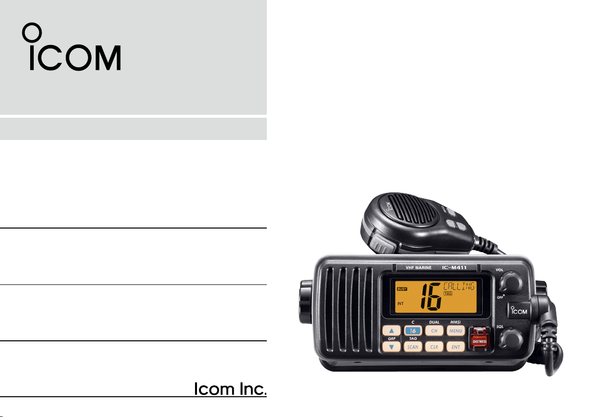
VHF MARINE TRANSCEIVER
iM411
Page 2
FOREWORD
IMPORTANT
Thank you for purchasing this Icom product. The IC-M411
vhf marine transceiver is designed and built with Icom’s
state of the art technology and craftsmanship. With proper
care, this transceiver should provide you with years of trou
ble-free operation.
We want to take a couple of moments of your time to thank
you for making the IC-M411 your radio of choice, and hope
you agree with Icom’s philosophy of “technology first.” Many
hours of research and development went into the design of
your IC-M411.
D FEATURES
m Advanced receiver performance
m Easy to hear speaker
m Built-in DSC meets Class D requirement
m Rugged waterproof construction
m Favorite channel function
m AquaQuake water draining function
Icom, Icom Inc. and the logo are registered trademarks of Icom Incorporated (Japan) in the United States, the United Kingdom, Germany, France,
Spain, Russia and/or other countries.
i
READ ALL INSTRUCTIONS carefully and completely
before using the transceiver.
-
SAVE THIS INSTRUCTION MANUAL — This in-
struction manual contains important operating instructions
for the IC-M411.
EXPLICIT DEFINITIONS
WORD DEFINITION
R WARNING!
CAUTION
NOTE
CLEA N THE T RANS C E I VER AND MI C R O P H ONE
THOROUGHLY WITH FRESH WATER after exposure
to water including salt water, otherwise, the keys and
switches may become inoperable due to salt crystalliza
tion.
Pers o nal injur y, fi re h azard or elect r ic
shock may occur.
Equipment damage may occur.
Recommended for optimum use. No risk of
personal injury, fire or electric shock.
-
Page 3

IN CASE OF EMERGENCY
INSTALLATION NOTE
If your vessel requires assistance, contact other vessels and
the Coast Guard by sending a Distress call on Channel 16.
USING CHANNEL 16
DISTRESS CALL PROCEDURE
1. “MAYDAY MAYDAY MAYDAY.”
2. “THIS IS ...............” (name of vessel)
3. Your call sign or other indication of the vessel (AND
9-digit DSC ID if you have one).
4. “LOCATED AT ...............” (your position)
5. The nature of the distress and assistance required.
6. Any other information which might facilitate the rescue.
Or, transmit your Distress call using digital selective calling
on Channel 70.
USING DIGITAL SELECTIVE CALLING (Ch 70)
DISTRESS CALL PROCEDURE
1. Wh i l e li f t in g up th e k e y co ver, p us h a n d h o l d
[DISTRESS] for 5 sec. until you hear 5 shor t beeps
change to one long beep.
2. Wait for an acknowledgment on Channel 70 from a
coast station.
• After the acknowledgement is received, Channel 16 is
automatically selected.
3. Push and hold
information as listed above.
[PTT], then transmit the appropriate
The installation of this equipment should be made in such a
manner as to respect the EC recommended electromagnetic
field exposure limits (1999/519/EC).
The maximum RF power available from this device is 25
watts. The antenna should be installed as high as possible
for maximum efficiency and that this insta llation height
should be at least 5 meters above ground (or accessible)
level. In the case where an antenna cannot be installed at
a reasonable height, then the transmitter should neither be
continuously operated for long periods if any person is within
5 meters of the antenna, nor operated at all if any person is
touching the antenna.
In all cases any possible risk depends on the transmitter
being activated for long periods. (Actual recommendation
limits are specified as an average of 6 minutes) Normally the
transmitter is not active for long periods of time. Some radio
licenses will require that a timer circuit automatically cuts the
transmitter after 1–2 minutes etc.
Similarly some types of transmitter, SSB, CW, AM, etc. have
a lower ‘average’ output power and the perceived risk is even
lower.
ii
Page 4
DOC
DECLARATION
OF CONFORMITY
We Icom Inc. Japan
1-1-32, Kamiminami, Hirano-ku
Osaka 547-0003, Japan
Kind of equipment:
VHF MARINE TRANSCEIVER
This compliances is based on conformity with the following harmonised
standards, specifications or documents:
i)
EN 301 025-2 V1.2.1 (2004-09)
ii)
EN 301 025-3 V1.2.1 (2004-09)
iii) EN 60945 2002
iv) EN 60950-1 2001
v) EN 300 698-2 V1.1.1 ( 2000-08)
vi) EN 300 698-3 V1.1.1 ( 2001-05)
Type-designation: iM411
Signature
Declare on our sole responsibility that this equipment complies with the
essential requirements of the Radio and Telecommunications Terminal
Equipment Directive, 1999/5/EC, and that any applicable Essential Test
Suite measurements have been performed.
Version (where applicable):
0560
Authorized representative name
Place and date of issue
26th Sep. 2007
CE versions of the IC-M411 which display the “CE”
symbol on the serial number seal, comply with the
essential requirements of the European Radio and
Telecommunication Terminal Directive 1999/5/EC.
This warning symbol indicates that this equipment ope rates in non-harmonised fre quency
bands and/or may be subject to licensing condi
tions in the country of use. Be sure to check that
you have the correct version of this radio or the
correct programming of this radio, to comply with
national licensing requirement.
iii
• List of Country codes (ISO 3166-1)
Country Codes Country Codes
1 Austria AT
2 Belgium BE
3 Bulgaria BG
-
4 Croatia HR
5 Czech Republic CZ
6 Cyprus CY
7 Denmark DK
8 Estonia EE
9 Finland FI
10 France FR
11 Germany DE
12 Greece GR
13 Hungary HU
14 Iceland IS
15 Ireland IE
16 Italy IT
17 Latvia LV
18 Liechtenstein LI
19 Lithuania LT
20 Luxembourg LU
21 Malta MT
22 Netherlands NL
23 Norway NO
24 Poland PL
25 Portugal PT
26 Romania RO
27 Slovakia SK
28 Slovenia SI
29 Spain ES
30 Sweden SE
31 Switzerland CH
32 Turkey TR
33 United Kingdom GB
Page 5

TABLE OF CONTENTS
FOREWORD ..................................................................................... i
IMPORTANT ...................................................................................... i
EXPLICIT DEFINITIONS ................................................................... i
IN CASE OF EMERGENCY ............................................................. ii
INSTALLATION NOTE ...................................................................... ii
DOC ................................................................................................. iii
TABLE OF CONTENTS ................................................................... iv
PRECAUTIONS ................................................................................ v
1 OPERATING RULES ..................................................................1
2 PANEL DESCRIPTION ........................................................... 2–4
n Front panel ............................................................................... 2
n Microphone ..............................................................................3
n Function display ....................................................................... 4
BASIC OPERATION ...............................................................5–9
3
n Channel selection .................................................................... 5
n Receiving and transmitting ......................................................7
n Call channel programming ....................................................... 8
n Channel comments .................................................................. 8
n Microphone Lock function ........................................................ 9
n Display backlight ...................................................................... 9
n AquaQuake water draining function .........................................9
SCAN OPERATION ............................................................10–11
4
n Scan types .............................................................................10
n Setting TAG channels ............................................................11
n Starting a scan ....................................................................... 11
DUALWATCH/TRI-WATCH .......................................................12
5
n Description ............................................................................. 12
n Operation ...............................................................................12
DSC OPERATION ............................................................... 13–38
6
n MMSI code programming ......................................................13
n DSC address ID ..................................................................... 14
n
Position and time programming ....................................................17
n Position indication .................................................................. 18
n Distress call ...........................................................................18
n Transmitting DSC calls ...........................................................21
n Receiving DSC calls ..............................................................32
n Received messages ..............................................................36
n Automatic acknowledgement ................................................ 38
n Offset time .............................................................................38
SET MODE .......................................................................... 39–41
7
n Set mode programming .........................................................39
n Set mode items ...................................................................... 40
CONNECTIONS AND MAINTENANCE..............................42–45
8
n Connections ........................................................................... 42
n Antenna .................................................................................43
n Fuse replacement ..................................................................43
n Cleaning................................................................................. 43
n Supplied accessories ............................................................. 43
n Mounting the transceiver .......................................................44
n Optional MB-69 installation .................................................... 45
TROUBLESHOOTING .............................................................. 46
9
10 SPECIFICATIONS AND OPTION .......................................47–49
n Specifications......................................................................... 47
n Option .................................................................................... 49
CHANNEL LIST ..................................................................50–51
11
12 TEMPLATE ............................................................................... 53
iv
Page 6

PRECAUTIONS
RWARNING! NEVER connect the transceiver to an
AC outlet. This may pose a fire hazard or result in an electric
shock.
NEVER connect the transceiver to a power source of more
than 16 V DC or use reverse polarity. This will ruin the trans
ceiver.
NEVER cut the DC power cable between the DC plug at
the back of the transceiver and fuse holder. If an incorrect
connection is made after cutting, the transceiver may be
damaged.
NEVER place the transceiver where normal operation of the
vessel may be hindered or where it could cause bodily injury.
KEEP the transceiver at least 1 m away from the ship’s
navigation compass.
DO NOT use or place the transceiver in areas with tem-
peratures below –20°C or above +60°C or, in areas subject
to direct sunlight, such as the dashboard.
AVOID the use of chemical agents such as benzine or al-
cohol when cleaning, as they may damage the transceiver
surfaces. If the transceiver becomes dusty or dirty, wipe it
clean with a soft, dry cloth.
BE CAREFUL! The transceiver rear panel will become
hot when operating continuously for long periods.
Place the transceiver in a secure place to avoid inadvertent
use by children.
-
BE CAREFUL! The transceiver employs waterproof
construction, which corresponds to IPX7 of the international
standard IEC 60529 (2001). However, once the transceiver
has been dropped, waterproofing cannot be guaranteed due
to the fact that the case may be cracked, or the waterproof
seal damaged, etc.
Icom optional equipment is designed for optimal perfor
mance when used with this transceiver. We are not respon
sible for the transceiver being damaged or any accident
caused when using non-Icom optional equipment.
-
-
v
Page 7

OPERATING RULES
1
D PRIORITIES
• Read all rules and regulations pertaining to priorities and
keep an up-to-date copy handy. Safety and Distress calls
take priority over all others.
• You must monitor Channel 16 when you are not operating
on another channel.
• False or fraudulent distress signals are prohibited and pun
ishable by law.
D PRIVACY
• Information overheard but not intended for you cannot lawfully be used in any way.
• Indecent or profane language is prohibited.
D RADIO LICENSES
(1) SHIP STATION LICENSE
You must have a current radio station license before using
the transceiver. It is unlawful to operate a ship station which
is not licensed.
Inquire through your dealer or the appropriate government
agency for a Ship-Radiotelephone license application. This
government-issued license states the call sign which is your
craft’s identification for radio purposes.
(2) OPERATOR’S LICENSE
A Restricted Radiotelephone Operator Permit is the license
most often held by small vessel radio operators when a radio
is not required for safety purposes.
The Restricted Radiotelephone Operator Permit must be
posted or kept with the operator. Only a licensed radio op
erator may operate a transceiver.
However, non-licensed individuals may talk over a trans
ceiver if a licensed operator starts, supervises, ends the call
and makes the necessary log entries.
Keep a copy of the current government rules and regulations
handy.
1
-
-
1
Page 8
2
Function
display (p. 4)
Speaker
i !0o
weu y t r
q
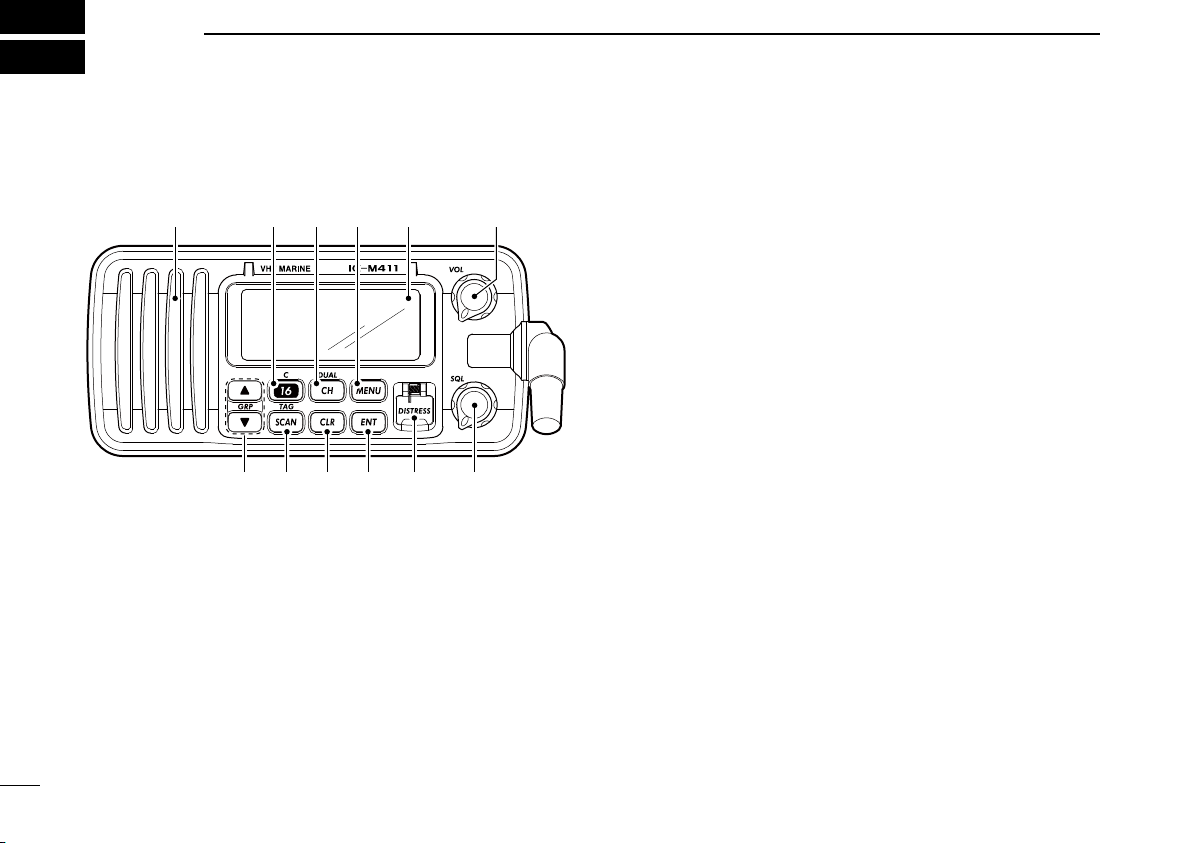
PANEL DESCRIPTION
n Front panel
q POWER/VOLUME CONTROL [VOL]
➥ Rotate to turn the transceiver power ON or OFF.
➥ Rotate to adjust the audio level.
w SQUELCH CONTROL [SQL] (p. 7)
Rotate to set the squelch threshold level.
e DISTRESS KEY [DISTRESS] (p. 18)
Push and hold for 3 sec. to transmit a distress call.
r ENTER KEY [ENT]
Sets the DSC menu, a channel comment, etc. when
pushed.
t CLEAR KEY [CLR]
Push to cancel the entered function and exits the condi
tion when pushed.
y SCAN/TAG CHANNEL KEY [SCAN•TAG] (p. 11)
➥ Push to start and stop the normal or priority scan when
tag channels are programmed.
➥ Push and hold for 1 sec. to set or clear the displayed
channel as a tag (scanned) channel.
➥ While pushing [HI/LO] located on the microphone,
push and hold for 3 sec. to set or clear all tag channels
in the selected channel group.
u CHANNEL UP/DOWN KEYS [s]/[t]•[GRP]
➥ Push to select the operating channels, Set mode set-
tings, DSC menu items, etc. (pgs. 5, 6, 13, 39)
➥ Push both keys to select a channel group in sequence.
(p. 6)
• EUR version has International channels only and this function is not available.
➥ Push to select the desired digit or character.
(pgs. 8, 13, 14, 17)
➥ While pushing [SCAN•TAG], push to adjust the bright-
ness of the LCD and key backlight. (p. 9)
➥ While pushing and holding both keys, turn power ON to
activates the AquaQuake function. (p. 9)
-
2
Page 9
i CHANNEL 16/CALL CHANNEL KEY [16•C]
Microphone
q
e
w
➥ Push to select Channel 16. (p. 5)
➥ Push and hold for 1 sec. to select call channel. (p. 5)
• “CALL” appears when call channel is selected.
➥ Push and hold for 3 sec. to enter the call channel pro-
gramming condition when the call channel is selected.
(p. 8)
➥ While pushing [CH•DUAL], push to enter the channel
comment programming condition. (p. 8)
➥
While turning power ON, push to enter set mode. (p. 39)
o CHANNEL/DUALWATCH/TRI-WATCH KEY [CH•DUAL]
➥ Push to select the regular channel. (pgs. 5, 6)
➥ Push and hold for 1 sec. to start dualwatch or tri-watch.
(p. 12)
➥ Push to stop dualwatch or tri-watch when either is acti-
vated. (p. 12)
!0 DSC MENU KEY [MENU] (p. 13)
Push to toggle the DSC menu ON or OFF.
PANEL DESCRIPTION
2
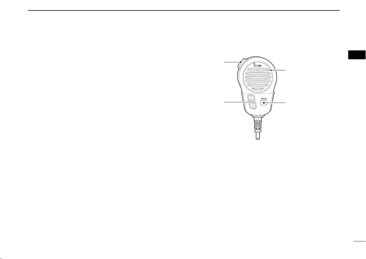
n Microphone
q PTT SWITCH [PTT]
Push and hold to transmit; release to receive. (p. 7)
w CHANNEL UP/DOWN KEYS [Y]/[Z]
➥ Push to select the operating channels, Set mode set-
tings, DSC menu items, etc. (pgs. 5, 6, 13, 39)
➥ Checks TAG channels, changes scanning direction or
resumes the scan manually during scan. (p. 11)
➥ Push to select the desired digit or character.
(pgs. 8, 13, 14, 17)
e TRANSMIT POWER KEY [HI/LO]
➥ Push to toggle the output power high and low. (p. 7)
• Some channels are set to low power only.
➥
While pushing and holding [HI/LO], turn power ON to
toggle the Microphone Lock function ON and OFF. (p. 9)
2
3
Page 10

PANEL DESCRIPTION
!1
!2
r
q
tu
!0
o
i
w
e
y
2
n Function display
q CHANNEL COMMENT INDICATOR
➥
‘Latitude,’ ‘Longitude’ and UTC time data scroll in sequence.
➥ Channel comment appears and scrolls (if programmed)
for about 10 sec. after the channel selection
➥
“DSC” appears when DSC channel group is in use; “ATIS”
appears when ATIS channel group is in use. (p. 6)
➥ “SCAN 16” appears during Priority scan; “SCAN” ap-
pears during Normal scan. (p. 11)
➥ “DW 16” appears during Dualwatch; “TW 16” appears
during Tri-watch. (p. 12)
➥
In Set mode, indicates and scrolls the selected item. (p. 39)
w TAG CHANNEL INDICATOR (p. 11)
Appears when a TAG channel is selected.
e DUPLEX INDICATOR (p. 6)
Appears when a duplex channel is selected.
r LOW BATTERY INDICATOR
Appears when the battery voltage drops to approx. 10 V
4
DC or below.
. (p. 8)
t DSC INDICATOR
Indicates the DSC status.
• “DSC” appears when a DSC call is received. (pgs. 22, 32)
• “POS REPLY” appears when a Position Reply call is received.
(p. 35)
y GPS INDICATOR
➥ Appears while valid position data is received.
➥ Blinks when invalid position data is received.
➥ Disappears when no GPS receiver is connected.
u CHANNEL NUMBER READOUT
➥ Indicates the selected operating channel number.
• “A” appears when a simplex channel is selected.
➥ In Set mode, indicates the selected condition. (p. 39)
i LOW POWER INDICATOR (p. 7)
Appears when low power is selected.
o CHANNEL GROUP INDICATOR (p. 6)
Indicates whether an International “
channel is in use. (Depends on version)
!0 CALL CHANNEL INDICATOR (p. 5)
Appears when the call channel is selected.
!1 BUSY INDICATOR (p. 7)
Appears when receiving a signal or when the squelch
opens.
!2 TRANSMIT INDICATOR (p. 7)
Appears while transmitting.
INT” or U.S.A. “USA”
Page 11
n Channel selection
Push
Push and hold
for 1 sec.
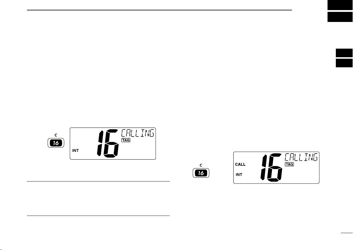
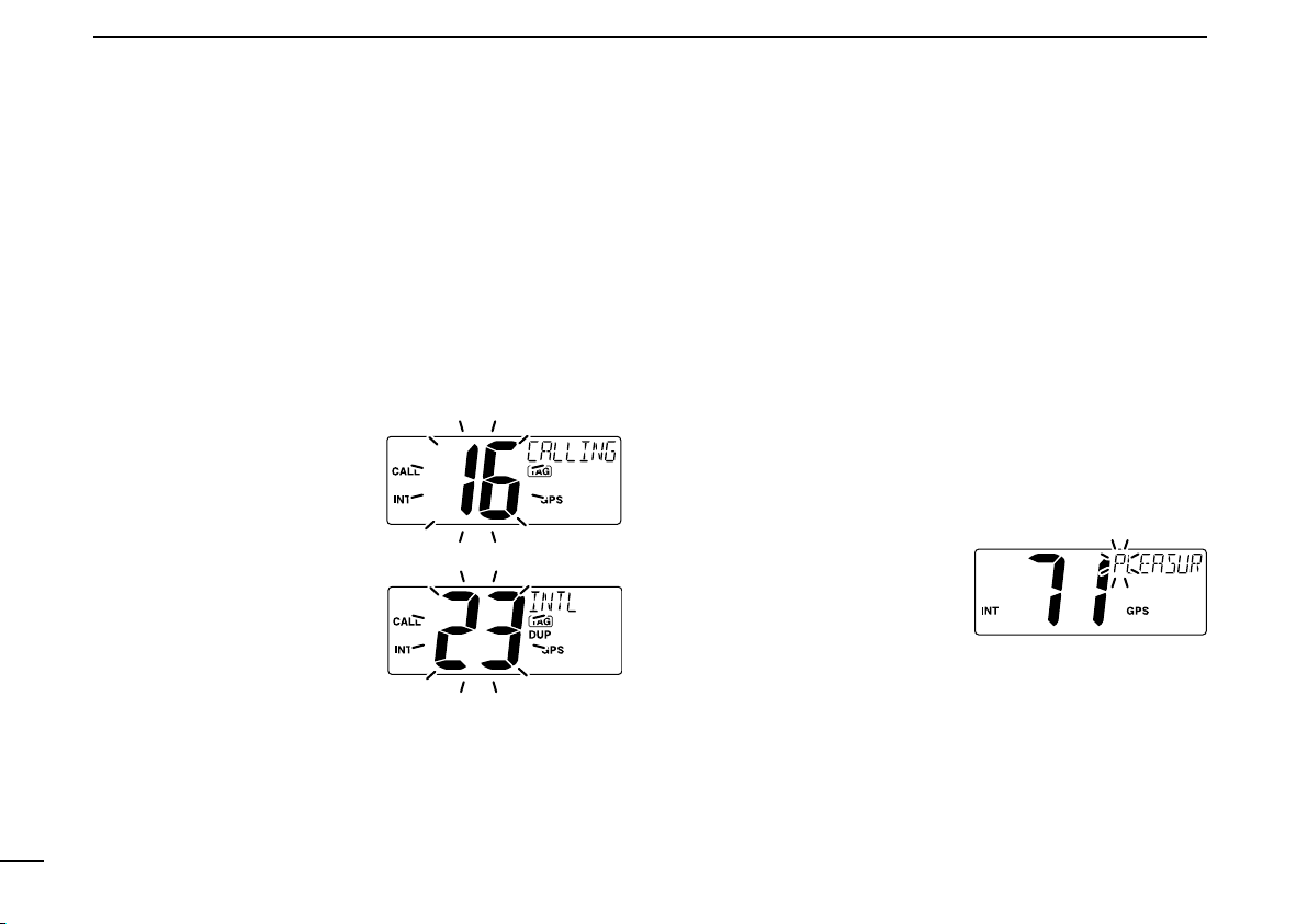
ï Channel 16
Channel 16 is the distress and safety channel. It is used for
establishing initial contact with a station and for emergency
communications. Channel 16 is monitored during both Du
alwatch and Tri-watch. While standing by, you must monitor
Channel 16.
BASIC OPERATION
ï Call channel
Each regular channel group has a separate leisure-use call
channel. The call channel is monitored during Tri-watch. The
call channels can be programmed (p. 8) and are used to
store your most often used channel in each channel group
for quick recall.
3
2
3
➥ Push [16•C] momentarily to select Channel 16.
➥ Push [CH•DUAL] to return to the condition before select-
Convenient!
When the Favorite channel function is turned ON (p. 41),
[Y]/[Z] keys on the microphone select the favorite channels
in the selected channel group in sequence when pushed.
• The favorite channels are set by the TAG channel setting. (p. 11)
ing Channel 16, or push
channel.
[Y] or [Z] to select an operating
➥ Push and hold [16•C] for 1 sec. to select the call channel
of the selected channel group.
• “CALL” and call channel number appear.
• Each channel group may have an independent call channel
after programming a call channel. (p. 8)
➥ Push [CH•DUAL] to return to the condition before select-
ing call channel, or push
channel.
[Y] or [Z] to select an operating
5
Page 12
BASIC OPERATION
Push
and
Push
and
Push and
ATIS channel
DSC channel*
*FRG version only
3
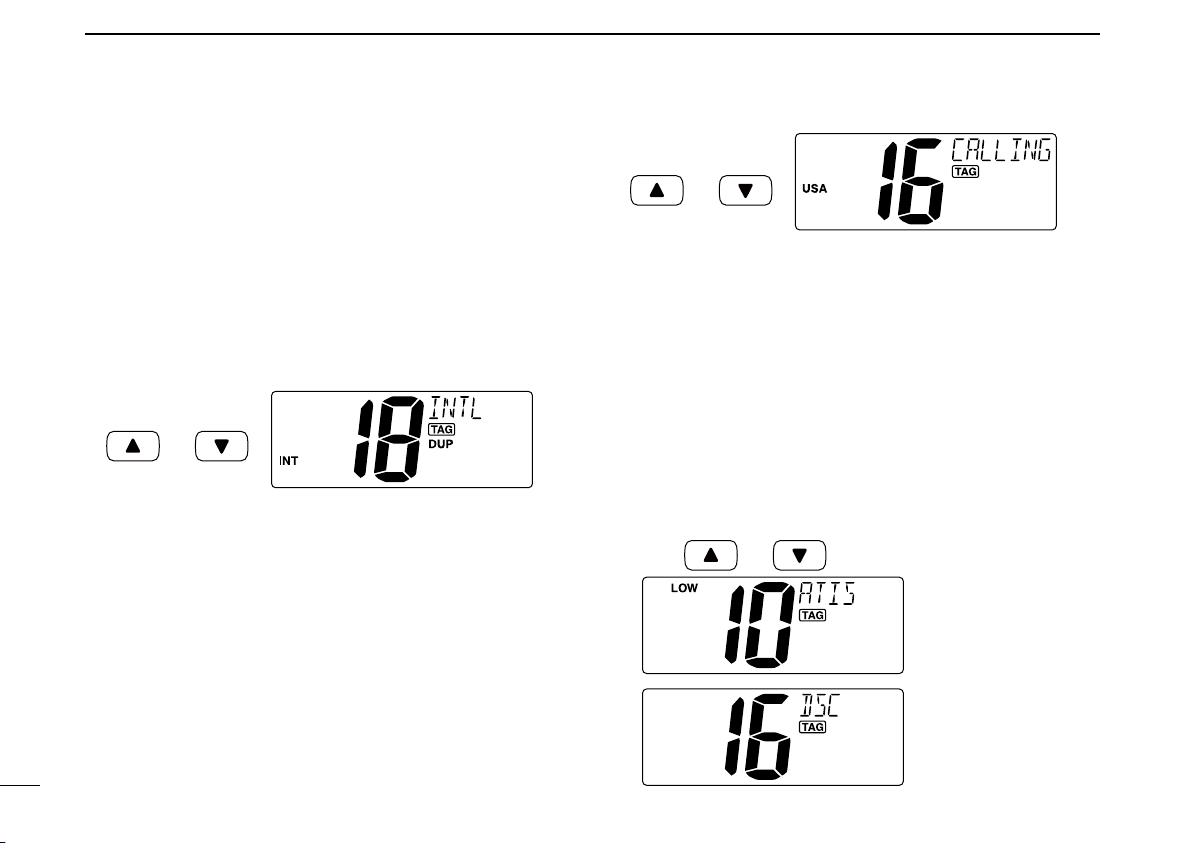
ï International channels
There are pre-programmed 57 (EUR version,) 59 (U.K. version,) 58 (Holland version) or 56 (FRG version) International
channels for the IC-M411.
q Push [CH•DUAL] to select a regular channel.
w Push both [s] and [t] on the transceiver to change the
channel group, if necessary.
• EUR version has International channels only and this function
is not available.
e Push [Y] or [Z] to select a channel.
• “DUP” appears for duplex channels.
ï U.S.A. channels (U.K. version only)
For U.K. version, there are pre-programmed 61 U.S.A. chan
nels in addition to 59 International channels.
q Push [CH•DUAL] to select a regular channel.
w Push both [s] and [t] on the transceiver to change the
channel group, if necessary.
• International and U.S.A. channels can be selected in sequence.
e Push [Y] or [Z] to select a channel.
• “DUP” appears for duplex channels.
6
ï ATIS and DSC channels
(Holland and FRG versions only)
For Holland and FRG version, there are pre-programmed 57
ATIS and 57 DSC* channels in addition to 58 (Holland ver
sion) or 56 (FRG version) International channels.
q Push [CH•DUAL] to select a regular channel.
w Push both [s] and [t] on the transceiver to change the
channel group, if necessary.
• International, ATIS and DSC* channels can be selected in se-
quence.
e Push [Y] or [Z] to select a channel.
• “DUP” appears for duplex channels.
-
-
Page 13
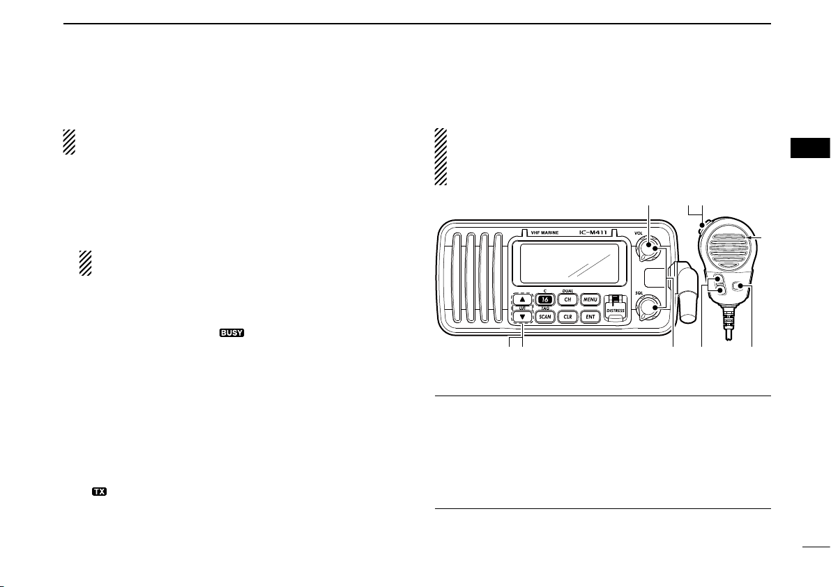
n Receiving and transmitting
u
w
re
M
q
y
r
t
M: Microphone
BASIC OPERATION
3
CAUTION: Transmitting without an antenna may dam-
age the transceiver.
q Rotate [VOL] to turn power ON.
w Set the audio and squelch levels.
➥Rotate [SQL] fully counterclockwise in advance.
➥Rotate [VOL] to adjust the audio output level.
➥Rotate [SQL] clockwise until the noise disappears.
While in the DSC operation, please make sure you set
the squelch correctly.
e Push both [Y] and [Z] on the transceiver to change the
channel group. (p. 6)
r
Push [Y] or [Z] to select the desired channel. (pgs. 5, 6, 50)
• When receiving a signal, “ ” appears and audio is emitted
from the speaker.
• Further adjustment of [VOL] may be necessary.
t Push [HI/LO] on the microphone to select the output
power if necessary.
• “LOW” appears when low power is selected.
• Choose low power for short range communications, choose
high power for longer distance communications.
• Some channels are for low power only.
y Push and hold [PTT] to transmit, then speak into the mi-
crophone.
• “ ” appears.
• Channel 70 cannot be used for transmission other than DSC.
u Release [PTT] to receive.
IMPORTANT: To maximize the readability of your trans-
mitted signal, pause a few sec. after pushing
the microphone 5 to 10 cm from your mouth and speak at
a normal voice level.
4 NOTE for TOT (Time-out Timer) function
The TOT function inhibits continuous transmission over a
preset time period after the transmission starts.
A beep sounds 10 sec. before the TOT function activates, to
indicate the transmission will be shut down and “TOT” ap
pears on the channel comment indicator. Transmission is not
possible for 10 sec. after this transmission shut down.
[PTT], hold
3
-
7
Page 14
BASIC OPERATION
3
n Call channel programming
You can program the call channel with your most often-used
channels in each channel group for quick recall.
q Push both [Y] and [Z] on the transceiver one or more
times to select the desired channel group (INT, USA, ATIS
or DSC) to be programmed.
w Push and hold [16•C] for 1 sec. to select the call channel
of the selected channel group.
• “CALL” and call channel number appear.
e Push and hold [16•C] again
for 3 sec. (until a long beep
changes to 2 short beeps)
to e nter th e call ch annel
programming condition.
• Channel number starts blinking.
r Push [Y] or [Z] to select
the desired channel.
t Push [16•C] to program the
disp layed ch annel as the
call channel.
• Push [CLR] to cancel.
• The channel number stops blinking.
n Channel comments
Memor y channels can be labeled with alphanumeric comments of up to 10 characters each for easy channel recogni
tion.
Comment is indicated at the channel comment indicator for
about 10 sec. after the channel selection, and the comment,
more than 7 characters long, automatically scrolls.
Capital letters, small letters (except f, j, k, p, s, v, x, z), 0 to 9,
some symbols (= M + – . /) and space can be used.
q Select the desired channel.
• Cancel Dualwatch, Tri-watch or Scan in advance.
w While pushing [CH•DUAL], push [16•C] to edit the chan-
nel comment.
• A cursor and the first character start blinking alternately.
e Select the desired charac-
ter by pushing
• Push [CH•DUAL] or [16•C]
to move the cursor forward or
backward, respectively.
r Repeat step e to input all characters.
t Push [ENT] to input and set the comment.
• Push [CLR] to cancel and exit the condition.
• The cursor and the character stop blinking.
y Repeat steps q to t to program other channel com-
ments, if desired.
[Y] or [Z].
-
8
Page 15

BASIC OPERATION
[HI/LO]
[Y]/[Z]
3
n Microphone Lock function
The Microphone Lock function electrically locks [Y]/[Z] on
the supplied microphone. This prevents accidental channel
changes and function access.
➥ While pushing [HI/LO] on the microphone, turn power ON
to toggle the Microphone Lock function ON and OFF.
n Display backlight
The function display and keys can be backlit for better visibility under low light conditions.
Display backlight is also adjustable via the Set mode. (p. 41)
n AquaQuake water draining
function
The IC-M411 uses a technology to clear water away from
the speaker grill: AquaQuake. AquaQuake helps drain water
away from the speaker housing (water that might otherwise
muffle the sound coming from the speaker). The IC-M411
emits a vibrating noise when this function is being used.
➥ While pushing and holding both [Y] and [Z] on the trans-
ceiver, turn power ON.
• A low beep tone sounds while [Y] and [Z] keys are pushed
and held to drain water, regardless of [VOL] control setting.
• The transceiver never accepts a key operation while the
Quake function is activated.
Aqua-
3
➥ While pushing [SCAN•TAG], push [Y] or [Z] to adjust
the brightness of the LCD and key backlight.
• The backlight is adjustable in 4 levels and OFF.
9
Page 16
4
CH 06
CH 01
CH 16
CH 02
CH 05 CH 04
CH 03
CH 01 CH 02
CH 06
CH 05 CH 04
CH 03
SCAN OPERATION
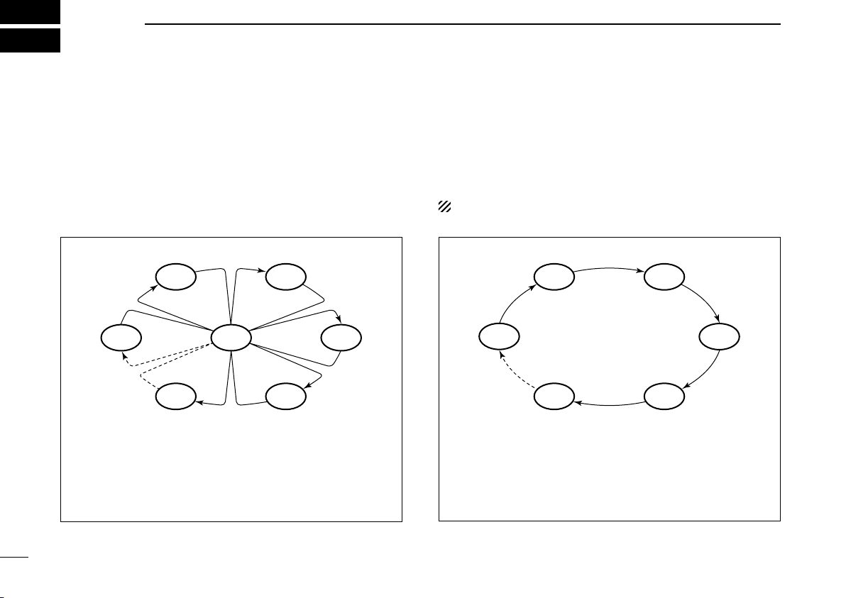
n Scan types
Scanning is an efficient way to locate signals quickly over a
wide frequency range. The transceiver has Priority scan and
Normal scan.
PRIORITY SCAN
Priority scan searches through all TAG channels in sequence while monitoring Channel 16. When a signal is
detected on Channel 16, scan pauses until the signal
disappears; when a signal is detected on a channel other
than Channel 16, scan becomes Dualwatch until the sig
nal disappears.
Set the TAG channels (scanned channel) before scanning.
Clear the TAG channels which inconveniently stop scanning,
such as those for digital communication use. (Refer to right
page for details.)
Choose Priority or Normal scan in Set mode. (p. 40)
NORMAL SCAN
Normal scan, like Priority scan, searches through all TAG
channels in sequence. However, unlike Priority scan,
Channel 16 is not checked unless Channel 16 is set as a
TAG channel.
-
10
Page 17
SCAN OPERATION
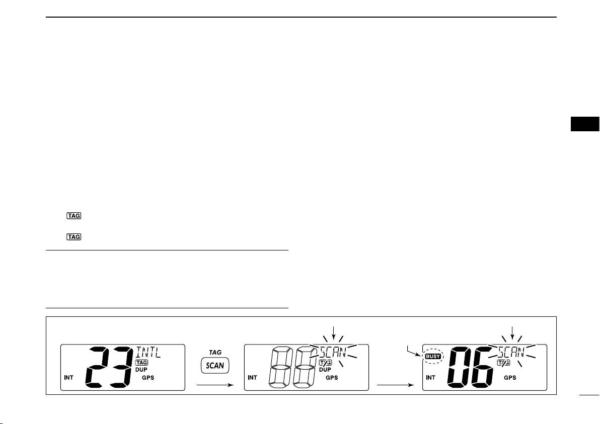
[Example]: Starting a Normal scan.
Push
Scan starts.
When a signal is
received.
BlinksBlinks
Appears
4
n Setting TAG channels
For more efficient scanning, add the desired channels as
TAG channels or clear the TAG for unwanted channels.
Channels that are not tagged will be skipped during scan
ning. TAG channels can be assigned to each channel group
(INT, USA, ATIS or DSC) independently.
q Push both [Y] and [Z ] to select the desired channel
group, if desired.
w Select the desired channel to be set as a TAG channel.
e Push and hold [SCAN•TAG] for 1 sec. to set the displayed
channel as a TAG channel.
• “ ” appears in the display.
r To cancel the TAG channel setting, repeat step e.
• “ ” disappears.
✓ Clearing (or setting) all tagged channels
While pushing
[SCAN•TAG] for 3 sec. (until a long beep changes to 2 short
beeps) to clear all TAG channels in the channel group.
• Repeat above procedure to set all TAG channels.
[HI/LO] on the microphone, push and hold
n Starting a scan
Set scan type (Priority or Normal scan) and scan resume
timer in advance, using Set mode. (p. 40)
-
q Push both [Y] and [Z ] to select the desired channel
group, if desired.
w Set TAG channels as described at left.
e Make sure the squelch is closed to start a scan.
r Push [SCAN•TAG] to start Priority or Normal scan.
• “SCAN” blinks at the channel comment indicator during scanning. (During Priority scan, “16” appears beside the blinking
“SCAN” indication.)
• A beep tone sounds and “16” blinks at the channel comment indicator when a signal is received on Channel 16 during Priority
scan.
• When a signal is detected, scan pauses until the signal disappears or resumes after pausing 5 sec. according to Set mode
setting. (Channel 16 is still monitored during Priority scan.)
• P ush [Y] or [ Z ] t o ch eck th e sc annin g TAG c hanne ls, to
change the scanning direction or resume the scan manually.
t To stop the scan, repeat step r.
4
11
Page 18
5
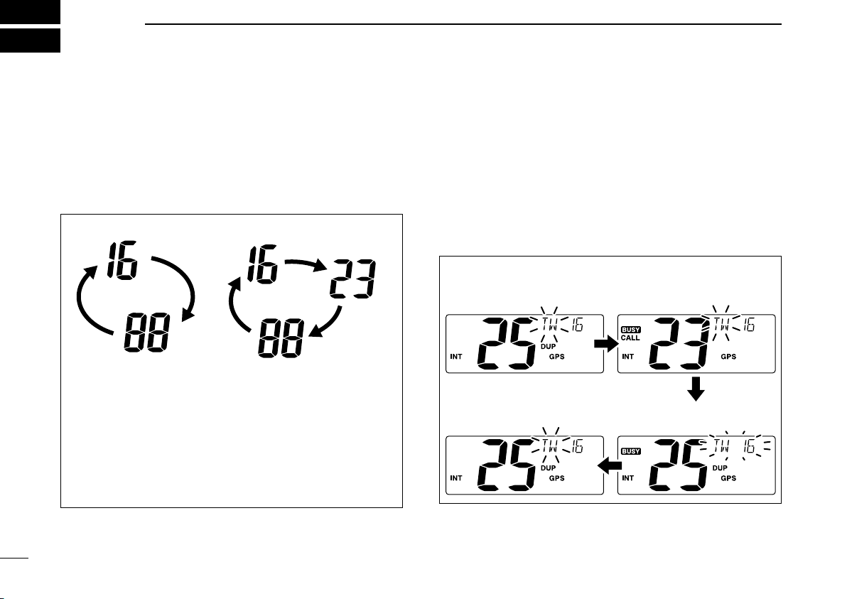
Dualwatch Tri-watch
Call channel
q Tri-watch starts. w Signal is received on
call channel.
e Signal is received on
Channel 16 takes priority.
r Tri-watch resumes after the
signal disappears.
DUALWATCH/TRI-WATCH
n Description
Dualwatch monitors Channel 16 while you are receiving on
another channel; Tri-watch monitors Channel 16 and the
call channel while receiving another channel. Dualwatch/Triwatch is convenient for monitoring Channel 16 when you are
operating on another channel.
DUALWATCH/TRI-WATCH SIMULATION
• If a signal is received on Channel 16, Dualwatch/Triwatch pauses on Channel 16 until the signal disappears.
• If a signal is received on the call channel during Triwatch, Tri-watch becomes Dualwatch until the signal dis
appears.
• To transmit on the selected channel during Dualwatch/
Tri-watch, push and hold
[PTT].
n Operation
q Select Dualwatch or Tri-watch in Set mode. (p. 40)
w Push [Y] or [Z] to select the desired channel.
e Push and hold [CH•DUAL] for 1 sec. to start Dualwatch
or Tri-watch.
• “DW” blinks during Dualwatch; “TW” blinks during Tri-watch.
• A beep tone sounds and “16” blinks when a signal is received
on Channel 16.
r To cancel Dualwatch/Tri-watch, push [CH•DUAL] again.
[Example]: Operating Tri-watch on INT Channel 25
-
12
Page 19
n MMSI code programming
Scrolls
Scrolls
DSC OPERATION
6
The 9-digit MMSI (Maritime Mobile Service Identity: DSC
self ID) code can be programmed at power ON.
This code programming can be performed only once.
After the code programming, it can be changed only
by your dealer or distributor.
q While pushing [MENU], turn power ON to enter MMSI
code programming condition.
• Turn power OFF in advance.
w After the display appears, release [MENU].
e Push [MENU] to enter the DSC menu.
r Push [Y] or [Z] to select “MMSI” and push [ENT].
• A cursor starts blinking.
t Input the specified MMSI code by pushing [Y] or [Z].
• Push [CH•DUAL] or [16•C] to move the cursor forward or backward, respectively.
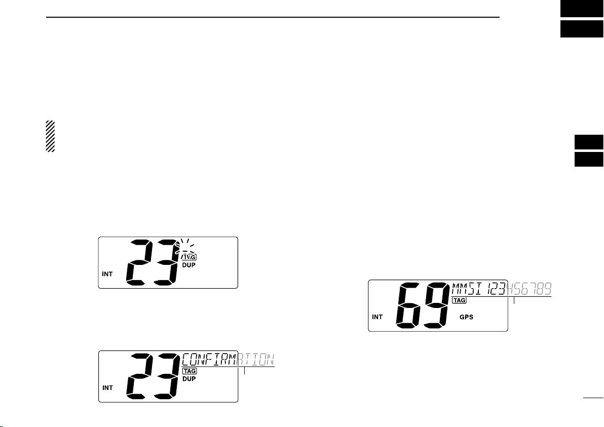
y After inputting the 9-digit MMSI code, push [ENT].
• “CONFIRMATION” scrolls at the channel comment indicator.
u Push [ENT], then input the same MMSI code as step t
for the confirmation.
Push [ENT] to set the code.
i
• Returns to the normal operation.
• Push [CLR] to cancel and exit the condition.
• If the different code is input, “INCORRECT” appears. Push
[ENT] and try steps t to u again.
D MMSI code check
The 9-digit MMSI (DSC self ID) code can be checked.
➥
Push [MENU] for 1 sec. to display the 9-digit MMSI (DSC
self ID) code.
• The MMSI code is displayed and scrolls at the channel comment indicator.
• When no MMSI code is programmed, “NO MMSI” appears and
warning alarm sounds.
5
6
13
Page 20
DSC OPERATION
Scrolls
6
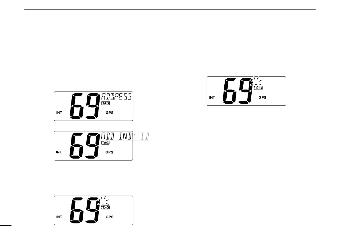
n DSC address ID
A total of 100 DSC address IDs (9-digit) can be programmed
and named with up to 10 characters.
D Programming Address ID
q Push [MENU] to enter the DSC menu.
w Push [Y] or [Z] to select “ADDRESS,” push [ENT].
e Push [Y] or [Z] to select “ADD INDV ID,” push [ENT].
r Push [Y] or [Z] to set the 9-digit Individual ID, push
[ENT].
• Push [CH•DUAL] or [16•C] to move the cursor forward or backward, respectively.
• Push [CLR] to cancel and exit the condition.
t Push [Y] or [Z] to set up to a 10-character ID name.
• Push [CH•DUAL] or [16•C] to move the cursor forward or backward, respectively.
• Push [CLR] to cancel and exit the condition.
y Push [ENT] to program and returns to the normal opera-
tion.
14
Page 21

DSC OPERATION
Scrolls
Scrolls
6
D Deleting Address ID
q Push [MENU] to enter the DSC menu.
w Push [Y] or [Z] to select “ADDRESS,” and push [ENT].
e Push [Y] or [Z] to select “DEL INDV ID,” push [ENT].
• When no address ID is programmed, “NO ID” is displayed.
r Push [Y] or [Z] to select the desired ID name for delet-
ing and push
• “READY” appears.
t Push [ENT] to delete the selected address ID and returns
to the normal operation.
[ENT].
D Programming Group ID
q Push [MENU] to enter the DSC menu.
w Push [Y] or [Z] to select “ADDRESS,” push [ENT].
6
e Push [Y] or [Z] to select “ADD GROUP ID,” push [ENT].
r Push [Y] or [Z] to set the 9-digit Group ID, push [ENT].
• Push [CH•DUAL] or [16•C] to move the cursor forward or backward, respectively.
• Push [CLR] to cancel and exit the condition.
1st digit ‘0’ is fixed for a Group ID.
☞ Continue to the next page
15
Page 22

DSC OPERATION
Scrolls
6
t Push [Y] or [Z] to set up to a 10-character ID name.
• Push [CH•DUAL] or [16•C] to move the cursor forward or backward, respectively.
• Push [CLR] to cancel and exit the condition.
y Push [ENT] to program and returns to the normal opera-
tion.
D Deleting Group ID
q Push [MENU] to enter the DSC menu.
w Push [Y] or [Z] to select “ADDRESS,” and push [ENT].
e Push [Y] or [Z] to select “DEL GROUP ID,” push [ENT].
• When no group ID is programmed, “NO ID” is displayed.
r Push [Y] or [Z] to select the desired ID name for delet-
ing and push
• “READY” appears.
t Push [ENT] to delete the selected group ID and returns
to the normal operation.
[ENT].
16
Page 23

n
Scrolls
Position and time programming
A distress call should include the ship’s position and time
data. If no GPS is connected, your position and UTC (Uni
versal Time Coordinated) time should be input manually.
They a re includ ed automa tically when a GPS receiver
(NMEA0183 ver. 2.0 or 3.01) is connected.
q Push [MENU] to enter the DSC menu.
w Push [s] or [t] to select “POSITION INPUT,” and push
[ENT].
e The position information appears. Set your latitude data
[s] or [t ]. After setting the latitude data, push
using
[ENT] to set your
• Push [CH•DUAL] or [16•C] to move the cursor forward or backward, respectively.
• Push [s] or [t] to edit N; North latitude or S; South latitude
when the cursor is on the ‘N’ or ‘S’ position, and W; West longitude or E; East longitude when the cursor is on the ‘W’ or ‘E’
position.
• Push [CLR] to cancel and exit the condition.
longitude data
.
DSC OPERATION
-
r After setting the longitude data, push [ENT] to set the
current UTC time using
• Push [CH•DUAL] or [16•C] to move the cursor forward or backward, respectively.
• Push [CLR] to cancel and exit the condition.
t Push [ENT] to program and returns to the normal opera-
tion.
Manually programmed position data will be held for 23.5
hours only.
“??” may blink instead of position and time indications
when the GPS data is invalid, or has not been manually
updated after 4 hours.
[s] or [t].
6
6
17
Page 24

DSC OPERATION
Scrolls
Scrolls
6
18
n Position indication
When a GPS receiver (NMEA0183 ver. 2.0 or 3.01) is connected, the transceiver displays the current position data in
seconds of accuracy.
A NMEA0183 ver. 2.0 or 3.01 (sentence formatters RMC,
GGA, GNS, GLL) compatible GPS receiver is required. Ask
your dealer about suitable GPS receivers.
➥ ‘Latitude,’ ‘Longitude’ and UTC time data scroll in se-
quence at the channel comment indicator.
• Channel comment is indicated at the channel comment indicator for about 10 sec. after the channel selection.
➥ “NO POSITION” scrolls when no GPS is connected.
• When the connected GPS receiver is compatible with
several sentence formatters, the order of input prece
dence is ‘RMC,’ ‘GGA,’ ‘GNS’ and ‘GLL.’
• “GPS” blinks when the GPS data is invalid.
n Distress call
A Distress call should be transmitted, if in the opinion of the
Master, the ship or a person is in distress and requires im
mediate assistance.
NEVER USE THE DISTRESS CALL WHEN YOUR
SHIP OR A PERSON IS NOT IN AN EMERGENCY.
A DISTRESS CALL CAN BE USED ONLY WHEN
IMMEDIATE HELP IS NEEDED.
D Simple call
q Confirm no Distress call is being received.
w While lifting up the key cover, push and hold [DISTRESS]
for 3 sec. to transmit the Distress call.
• Emergency channel (Ch 70) is automatically selected and the
Distress call is transmitted.
• While pushing and holding [DISTRESS], the key backlighting is
blinking.
-
e After transmitting the Distress call, the transceiver waits
for an acknowledgment call on Ch16.
• The Distress call is automatically transmitted every 3.5 to 4.5
minutes.
• “DSC REPEAT” scrolls at the channel comment indicator.
-
Page 25

Scrolls
r After receiving the acknowledgment, reply using the mi-
Scrolls
Scrolls
Scrolls
crophone.
• “RCV DISTRESS ACK” scrolls at the channel comment indicator.
➥A distress alert contains;
• Kinds of distress: Undesignated distress
• Position data : Latest GPS or manual input position data
held for 2 3.5 h rs. o r unt il the po wer is
turned OFF.
➥ The Distress call is repeated every 3.5–4.5 min., until
receiving an ‘acknowledgement.’ (‘Call repeat’ mode)
• “RE-TRANSMISSION” is displayed while transmission.
➥ Push [DISTRESS] to transmit a renewed Distress call,
if desired.
➥
Push [CLR] to transmit a the ‘Cancel ACK’ call to cancel the ‘Call repeat’ mode.
• “CANCELED” is displayed.
DSC OPERATION
6
D Regular call
The nature of the distress call should be included in the distress call.
q Push [MENU] to enter the DSC menu.
w Push [s] or [t] to select “DISTRESS,” and push [ENT].
e Push [s] or [t] to select the nature of the distress, push
[ENT].
• ‘UNDESIGNATED,’ ‘EXPLOSION,’ ‘FLOODING,’ ‘COLLISION,’
‘GROUNDING,’ ‘CA PS IZING,’ ‘SINKING,’ ‘AD RI FT (D is able
adrift),’ ‘ABANDONING (Abandoning ship),’ ‘PIRACY (Piracy attack),’ and ‘MOB (Man overboard)’ are available.
• The selected nature of the distress is stored for 10 minutes.
When a GPS receiver (NMEA0183 ver. 2.0 or 3.01) is
connected, next steps r, t (Current position/time programming) do not appear. Go to step
☞ Continue to the next page
y.
6
19
Page 26

Scrolls
Scrolls
Scrolls
DSC OPERATION
6
r The position information appears. Set your latitude data
[s] or [t ]. After setting the latitude data, push
using
[ENT] to set your
• Push [CH•DUAL] or [16•C] to move the cursor forward or backward, respectively.
•
Push [s] or [t] to edit N; North latitude or S; South latitude when
the cursor is on the ‘N’ or ‘S’ position, and W; West longitude or E;
East longitude when the cursor is on the ‘W’ or ‘E’ position.
• Push [CLR] to cancel and exit the condition.
t After setting the
rent UTC time using
• Push [CH•DUAL] or [16•C] to move the cursor forward or backward, respectively.
• Push [CLR] to cancel and exit the condition.
longitude data
longitude
.
data, push [ENT] to set the cur-
[s] or [t], then push [ENT].
y Push [DISTRESS] for 3 sec. to transmit the distress call.
• While pushing [DISTRESS], the key backlighting is blinking.
• The distress information is stored for 10 minutes.
• Emergency channel (Ch70) is automatically selected and the
Distress call is transmitted.
• Push [CLR] to exit the condition.
u After transmitting the distress call, the transceiver waits
for an acknowledgment call on Ch 16.
• The distress call is automatically transmitted every 3.5 to 4.5 min.
i After receiving the acknowledgment, reply using the mi-
crophone.
20
Page 27

DSC OPERATION
Scrolls
Scrolls
6
➥A distress alert contains (default);
• Nature of distress : Selected nature of the distress
• Position data :
➥ The Distress call is repeated every 3.5–4.5 min., until re-
ceiving an ‘acknowledgement.’ (‘Call repeat’ mode)
• “RE-TRANSMISSION” is displayed.
➥ Push [DISTRESS] to transmit a renewed Distress call,
if desired.
➥
Push [CLR] to transmit a the ‘Cancel ACK’ call to cancel the ‘Call repeat’ mode.
• “CANCELED” is displayed.
➥ “??” may blink instead of position and time indications
when the GPS data is invalid, or has not been manu
ally updated after 4 hours.
GPS or manual input position data is held
for 23.5 hrs or until the power is turned OFF.
n Transmitting DSC calls
To ensure correct operation of the DSC function, please
make sure you set the squelch correctly. (p. 7)
D Transmitting an Individual call
The Individual call function allows you to transmit a DSC signal to a specific ship only.
q Push [MENU] to enter the DSC menu.
w Push [Y] or [Z] to select “INDIVIDUAL,” push [ENT].
-
e Push [Y] or [Z] to select the desired pre-programmed
Individual address, push
• The ID code must be set in advance. (p. 14)
[ENT].
☞ Continue to the next page
6
21
Page 28

DSC OPERATION
Push
Transmitting
Scrolls
‘Able to comply’ is received.
‘Unable to comply’ is received.
Scrolls
Scrolls
6
22
r Push [Y] or [Z] to select the desired intership channel,
push [ENT].
• Intership channels are already preset into the transceiver in
preferred order.
• After pushing [ENT], Channel 70 is automatically selected and
“READY” appears at the channel comment indicator.
t Push [ENT] to transmit the Individual call.
• If Channel 70 is busy, the transceiver stands by until the channel becomes clear.
• Routine category only is available.
y Stands by on the intership channel, specified in step r,
until an acknowledgement is received.
• “WAIT ACK” scrolls at the channel comment indicator.
u When the acknowledgement is received, “DSC” appears
and “RCV ABLE ACK” or “RCV UNABLE ACK” scrolls at
the channel comment indicator with beeps.
• Push [CLR] to stop the beep.
i Push and hold [PTT] to communicate your message to
the responding ship when ‘Able to comply.’
• Push [CLR] to return to the operated channel (before entering
the DSC menu) when ‘Unable to comply’ is received.
Page 29

Scrolls
Scrolls
‘ABLE’ is
selected.
Push
Transmitting
Scrolls
After transmitting ‘ABLE’ ACK
D Transmitting an Individual acknowledgement
When receiving an Individual call, you can transmit an acknowledgement (‘Able to comply’ or ‘Unable to comply’) by
using the on screen prompts (Quick ACK.) Also, you can send
an acknowledgement through the menu system (Manual ACK.)
Quick ACK:
➥ After an Individual call is received, push [CLR] to stop
beep, then push [ENT]. (Go to step r as below.)
Manual ACK:
q Push [MENU] to enter the DSC menu.
w Push [Y] or [Z] to select “INDV ACK,” push [ENT].
• “INDV ACK” item appears after receiving an Individual call.
e Push [Y] or [Z] to select the desired individual address,
push [ENT].
r Push [Y] or [Z] to select the acknowledgement “ABLE”
or “UNABLE,” push [ENT].
•
“UNABLE” selection will transmit the reason “No Reason Given”.
• After pushing [ENT], Channel 70 is automatically selected and
“READY” appears at the channel comment indicator.
DSC OPERATION
6
t Push [ENT] to transmit the acknowledgement call to the
selected station.
y After the Individual acknowledgement call has been trans-
mitted, the specified channel (specified by the calling sta
tion) is selected automatically when “ABLE” is selected,
or returns to the previous condition (before entering the
DSC menu) when “UNABLE” is selected in step
e.
6
-
23
Page 30

DSC OPERATION
Push
Transmitting
Scrolls
6
D Transmitting a Group call
The Group call function allows you to transmit a DSC signal
to a specific group only.
q Push [MENU] to enter the DSC menu.
w Push [Y] or [Z] to select “GROUP,” push [ENT].
24
e Push [Y] or [Z] to select the desired pre-programmed
Group address, push [ENT].
• The ID code must be set in advance. (p. 15)
r Push [Y] or [Z] to select the desired intership channel,
push [ENT].
• Intership channels are already preset into the transceiver in
recommending order.
• After pushing [ENT], Channel 70 is automatically selected and
“READY” appears at the channel comment indicator.
t Push [ENT] to transmit the Group call.
• If Channel 70 is busy, the transceiver stands by until the channel becomes clear.
• Routine category only is available.
y After the Group call has been transmitted, the specified
channel (in step
r) is automatically selected.
u Push and hold [PTT] to communicate your message to
the responding ship.
Page 31

Scrolls
Push
Transmitting
Scrolls
D Transmitting an All Ships call
Large ships use Channel 70 as their ‘listening channel.’
When you want to announce a message to these ships
within range, use the
q Push [MENU] to enter the DSC menu.
w Push [Y] or [Z] to select “ALL SHIPS,” push [ENT].
e Push [Y] or [Z] to select the desired category, push
[ENT].
• Output power of ‘Routine’ category is 1 W (low power) only.
• Th e selectable c ate gor y may dif fe r ac cor din g to t he p rogrammed setting. Ask your dealer for the available categories.
r Push [Y] or [Z] to select the desired ITU channel, push
[ENT].
• After pushing [ENT], Channel 70 is automatically selected and
“READY” appears at the channel comment indicator.
‘
All Ships call’ function.
DSC OPERATION
t Push [ENT] to transmit the All Ships call.
y After the All Ships call has been transmitted, the specified
channel (in step
r) is selected automatically.
6
6
25
Page 32

DSC OPERATION
Scrolls
Scrolls
Push
Transmitting
Scrolls
6
D Transmitting a Position Request call
Transmit a Position Request call when you want to know a
specified ship’s current position, etc.
q Push [MENU] to enter the DSC menu.
w Push [Y] or [Z] to select “POS REQUEST,” push [ENT].
e Push [Y] or [Z] to select the desired pre-programmed
Individual address, push
• The ID code must be set in advance. (p. 14)
• After pushing [ENT], Channel 70 is automatically selected and
“READY” appears at the channel comment indicator.
[ENT].
r Push [ENT] to transmit the Position Request call.
t After the Position Request call has been transmitted, re-
turns to the normal operation.
26
Page 33

D Transmitting a Position Reply call
Scrolls
Scrolls
Transmitting
Scrolls
Transmit a Position Reply call when a Position Request call
is received.
q Push [MENU] to enter the DSC menu.
w Push [Y] or [Z] to select “POS REPLY,” push [ENT].
• “POS REPLY” item appears after receiving a Position Request
call.
e Push [Y] or [Z] to select the desired individual address,
push [ENT].
r The position information appears. Input your position data
(latitude and longitude) directly with
[Y] or [Z]. (p. 17)
DSC OPERATION
t After editing the position data, push [ENT] to set. Then
edit the current UTC time directly with
push [ENT].
• After pushing [ENT], Channel 70 is automatically selected and
“READY” appears at the channel comment indicator.
y Push [ENT] to transmit the Position Reply call.
u After the Position Reply call has been transmitted, returns
to the normal operation.
[Y] or [Z] (p. 17),
6
6
27
Page 34

DSC OPERATION
Scrolls
Scrolls
Push
Transmitting
Scrolls
6
D Transmitting a Polling Request call
Transmit a Polling Request call when you want to know a
specific ship is in the communication area, etc.
q Push [MENU] to enter the DSC menu.
w Push [Y] or [Z] to select “POLL REQUEST,” push [ENT].
e Push [Y] or [Z] to select the desired pre-programmed
Individual address, push
• The ID code must be set in advance. (p. 14)
• After pushing [ENT], Channel 70 is automatically selected and
“READY” appears at the channel comment indicator.
[ENT].
r Push [ENT] to transmit the Polling Request call.
t After the Polling Request call has been transmitted, re-
turns to the normal operation.
28
Page 35

D Transmitting a Polling Reply call
Scrolls
Scrolls
Push
Transmitting
Scrolls
Transmit a Polling Reply call when a Polling Request call is
received.
q Push [MENU] to enter the DSC menu.
w Push [Y] or [Z] to select “POLL REPLY,” push [ENT].
• “POLL REPLY” item appears after receiving a Polling Request
call.
e Push [Y] or [Z] to select the desired individual address,
push [ENT].
• After pushing [ENT], Channel 70 is automatically selected and
“READY” appears at the channel comment indicator.
DSC OPERATION
r Push [ENT] to transmit the Polling Reply call.
t After the Polling Reply call has been transmitted, returns
to the normal operation.
6
6
29
Page 36

DSC OPERATION
Scrolls
Scrolls
Push
Transmitting
Scrolls
6
D Test Call
Testing on the exclusive DSC distress and safety calling channels should be avoided as much as possible by using other
methods. When testing on the distress/safety channel is una
voidable, it should be indicated that these are test transmissions.
Normally the test call would require no further communications between the two stations involved.
q Push [MENU] to enter the DSC menu.
w Push [s] or [t] to select “TEST CALL,” and push [ENT].
e Push [Y] or [Z] to select the desired pre-programmed
coast station address, push
• The ID code must be set in advance. (p. 14)
• After pushing [ENT], Channel 70 is automatically selected and
“READY” appears at the channel comment indicator.
[ENT].
r Push [ENT] to transmit the Test call.
• If Channel 70 is busy, the transceiver stands by until the chan-
-
nel becomes clear.
t After the Test call has been transmitted, returns to the
normal operation.
30
Page 37

DSC OPERATION
Scrolls
Scrolls
Push
Transmitting
Scrolls
6
D Transmitting a Test Ack call
Transmit a Test Acknowledgement call when a Test call is
received.
q Push [MENU] to enter the DSC menu.
w Push [Y] or [Z] to select “TEST ACK,” push [ENT].
• “TEST ACK” item appears after receiving a Polling Request call.
e Push [Y] or [Z] to select the desired individual address,
push [ENT].
• After pushing [ENT], Channel 70 is automatically selected and
“READY” appears at the channel comment indicator.
r Push [ENT] to transmit the Test Ack call.
t After the Test Ack call has been transmitted, returns to
the normal operation.
1
2
3
4
5
6
7
8
9
10
11
12
13
14
15
16
31
Page 38

DSC OPERATION
Scrolls
Scrolls
Scrolls
Scrolls
6
n Receiving DSC calls
D Receiving a Distress call
While monitoring Channel 70 and a Distress call is received:
➥ The emergency alarm sounds for 2 minutes.
• Push any key to stop the alarm.
➥ “DSC” appears and “RCV DISTRESS” scrolls at the chan-
nel comment indicator, then Channel 16 is selected auto
matically.
➥ Continue monitoring Channel 16 as a coast station may
require assistance.
D Receiving a Distress Acknowledgement
While monitoring Channel 70 and a Distress acknowledgement to other ship is received:
➥ The emergency alarm sounds for 2 minutes.
• Push any key to stop the alarm.
➥“DSC” appears and “RCV DISTRESS ACK” scrolls at the
channel comment indicator, then Channel 16 is selected
automatically.
D Receiving a Distress Relay call
While monitoring Channel 70 and a Distress Relay is received:
➥ The emergency alarm sounds for 2 minutes.
• Push any key to stop the alarm.
-
➥ “DSC” appears and “RCV RELAY” scrolls at the channel com-
ment indicator, then Channel 16 is selected automatically.
D
Receiving a Distress Relay Acknowledgement
While monitoring Channel 70 and a Distress Relay acknowledgement is received:
➥ The emergency alarm sounds for 2 minutes.
• Push any key to stop the alarm.
➥ “DSC” appears and “RCV RELAY ACK” scrolls at the channel
comment indicator, then Channel 16 is selected automatically.
32
Page 39

DSC OPERATION
Scrolls
Scrolls
6
1
D Receiving an Individual call
While monitoring Channel 70 and an Individual call is received:
➥ The emergency alarm or beeps sound for 2 minutes de-
pending on the received category.
• Push [CLR] to stop the alarm or beeps.
➥ “DSC” appears and “RCV INDIVIDUAL” scrolls at the chan-
nel comment indicator.
➥ Push [ENT] to reply the call and select the channel speci-
fied by the calling station for voice communication (de
pending on your replying condition. See p, 23 for Individual
acknowledgement call procedure for details.); push
other key to ignore the call.
[CLR]
D Receiving a Group call
While monitoring Channel 70 and a Group call is received:
➥ The emergency alarm or beeps sound for 2 minutes de-
pending on the received category.
• Push [CLR] to stop the alarm or beeps.
➥ “DSC” appears and “RCV GROUP” scrolls at the channel
comment indicator.
➥
Push [ENT] to select the channel specified by the calling station for voice communication; push
-
[CLR] to ignore the call.
2
3
4
5
6
7
8
9
10
11
12
13
14
15
16
33
Page 40

DSC OPERATION
Scrolls
Scrolls
6
D Receiving an All Ships call
While monitoring Channel 70 and an All Ships call is received:
➥ The emergency alarm sounds for 2 minutes depending
on the received categories.
• Push [CLR] to stop the alarm or beeps.
➥ “DSC” appears and “RCV ALL SHIPS” scrolls at the chan-
nel comment indicator.
➥ Push [ENT] to monitor Channel 16 for an announcement
from the calling vessel, push
[CLR] to ignore the call.
D Receiving a Geographical Area call
While monitoring Channel 70 and a Geographical Area call
(for the area you are in) is received:
➥ The emergency alarm or beeps sound for 2 minutes de-
pending on the received category.
• Push [CLR] to stop the alarm or beeps.
➥ “DSC” appears and “RCV GEOGRAPHICAL” scrolls at
the channel comment indicator.
➥ Push [ENT] to select the channel specified by the calling sta-
tion for voice communication; push
➥ Monitor the selected channel for an announcement from
the calling station.
When no GPS receiver is connected or if there is a prob-
lem with the connected receiver, all Geographical Area
calls are received, regardless of your position.
[CLR] to ignore the call.
34
Page 41

DSC OPERATION
Scrolls
Scrolls
Scrolls
Scrolls
6
D Receiving a Position Request call
While monitoring Channel 70 and a Position Request call is
received:
➥ “DSC” appears and “RCV POS REQUEST” scrolls at the
channel comment indicator.
➥ The beeps sound for 2 minutes.
• Push [CLR] to stop the beeps.
➥
Push [ENT] to reply to the call; push [CLR] to ignore the call.
D Receiving a Polling Request call
While monitoring Channel 70 and a Polling Request call is
received:
➥ “DSC” appears and “RCV POLL REQUEST” scrolls at the
channel comment indicator.
➥ The beeps sound for 2 minutes.
• Push [CLR] to stop the beeps.
➥
Push [ENT] to reply to the call; push [CLR] to ignore the call.
D Receiving a Position Reply call
While monitoring Channel 70 and a Position Request Reply
call is received:
➥“DSC” and “POS REPLY” appear in the display.
• The ‘Latitude’ and ‘Longitude’ from the called station is displayed and scrolled at the channel comment indicator in order
of Latitude co-ordinates and then Longitude co-ordinates.
• “NO POSITION” scrolls at the channel comment indicator when
no position information is received.
➥ The beeps sound for 2 minutes.
• Push [CLR] to stop the beeps.
D Receiving a Polling Reply call
While monitoring Channel 70 and a Polling Reply call is received:
➥ “DSC” appears and “RCV POLL REPLY” scrolls at the
channel comment indicator.
➥ The beeps sound for 2 minutes.
• Push [CLR] to stop the beeps.
1
2
3
4
5
6
7
8
9
10
11
12
13
14
15
16
35
Page 42

DSC OPERATION
Scrolls
Scrolls
Scrolls
Scrolls
6
D Receiving a Test call
While monitoring Channel 70 and a Test call is received:
➥ “DSC” app ears and “RCV TEST CALL” scro lls at the
channel comment indicator.
➥ The beeps sound for 2 minutes.
• Push [CLR] to stop the beeps.
➥
Push [ENT] to reply to the call; push [CLR] to ignore the call.
D Receiving a Test Acknowledgement call
While monitoring Channel 70 and a Test Acknowledgement
call is received:
➥ “DSC” appears and “RCV TEST ACK” scrolls at the chan-
nel comment indicator.
➥ The beeps sound for 2 minutes.
• Push [CLR] to stop the beeps.
➥
Push [ENT] to reply to the call; push [CLR] to ignore the call.
n Received messages
The transceiver automatically stores up to 20 distress messages and 20 other messages. The messages can be used
as an assistance to the logbook.
D Distress message
q Push [MENU] to enter the DSC menu.
w Push [s] or [t] to select “DSC LOG,” and push [ENT].
e Push [s] or [t] to select “DISTRESS,” push [ENT].
r
Push [s] or [t] to select the desired message, push [ENT].
• “M” appears when the unread messages is selected.
36
Page 43

DSC OPERATION
Scrolls
Scrolls
Scrolls
6
1
t The message information scrolls.
• The stored message has various information.
• Push [CLR] to exit the condition.
• Push and hold [CLR] for 1 sec. to delete the displayed message and returns to DSC menu.
D Other messages
q Push [MENU] to enter the DSC menu.
w Push [s] or [t] to select “DSC LOG,” and push [ENT].
e Push [s] or [t] to select “OTHER,” push [ENT].
r
Push [s] or [t] to select the desired message, push [ENT].
• “M” appears when the unread messages is selected.
t The message information scrolls.
• The stored message has various information.
• Push [CLR] to exit the condition.
• Push and hold [CLR] for 1 sec. to delete the displayed message and returns to DSC menu.
2
3
4
5
6
7
8
9
10
11
12
13
14
15
16
37
Page 44

DSC OPERATION
Scrolls
Scrolls
6
38
n Automatic acknowledgement
This item sets the automatic acknowledgement function ON
or OFF.
When a position request or polling request call is received,
transceiver automatically transmits a position request reply
or polling reply call, respectively.
q Push [MENU] to enter the DSC menu.
w Push [s] or [t] to select “AUTO ACK,” and push [ENT].
e Push [s] or [t]
function ON or OFF
r Push [ENT] to set the condition.
• Push [CLR] to cancel and exit the condition.
to turn the
.
automatic acknowledgement
n Offset time
This item sets the offset time from the UTC (Universal Time
Coordinated) time.
q Push [MENU] to enter the DSC menu.
w Push [s ] or [t] to select “OFFSET TIME,” and push
[ENT].
e Set the offset time from the UTC (Universal Time Coordi-
nated) time using
• Push [CH•DUAL] or [16•C] to move the cursor forward or backward, respectively.
• Push [CLR] to cancel and exit the condition.
r Push [ENT] to program and to exit the condition.
The local time indication is not available when the GPS
receiver (sentence formatter RMC) is connected, the
transceiver’s display indicates UTC time only.
[s] or [t].
Page 45

SET MODE
• Dual/Tri-watch
• Scan resume
timer
• Operation beep
• AF level
adjustment
• LCD Contrast
• LCD Backlight
• Favorite channel • Scan type
, turn power ON.• To enter Set mode: While pushing
• To exit Set mode: Turn power OFF, then ON again.
• To select the item: Push . ( )
Starting item
Scrolls
Scrolls
Scrolls
7
n Set mode programming
Set mode is used to change the conditions of the transceiver’s functions: Scan type, Scan resume timer, Dual/Triwatch, Operation beep, LCD backlight, LCD contrast, AF
level adjustment and Favorite channel.
Available functions may differ depending on dealer set-
ting.
D SET MODE CONSTRUCTION
q
Turn power OFF.
w While pushing [16•C], turn power ON to enter Set mode.
• “SCAN” appears at the channel comment indicator.
e After the display appears, release [16•C].
r Push [16•C] to select the desired item, if necessary.
t
Push [Y] or [Z] to select the desired condition of the
item.
y Turn power OFF, then ON again to exit Set mode.
1
2
3
4
5
6
7
8
9
10
11
12
13
14
15
16
39
Page 46

Priority scan (default) Normal scan
Scan timer OFF (default)
Scan timer ON
Dualwatch (default) Tri-watch
Beep tone ON (default) Beep tone OFF
SET MODE
7
n Set mode items
D Scan type
The transceiver has 2 scan types: Normal scan and Priority
scan. Normal scan searches all TAG channels in the se
lected channel group. Priority scan searches all TAG chan
nels in sequence while monitoring Channel 16.
D Scan resume timer
The scan resume timer can be selected as a pause (OFF) or
timer scan (ON).
ON : The scan pauses 5 sec. and resumes even if a signal
has been received on any other channel than Chan
nel 16.
OFF : The scan pauses until the signal disappears.
D Dual/Tri-watch
This item can be selected as Dualwatch or Tri-watch. (p. 12)
-
-
D Operation beep
You can select the silent operation by turning beep tones
OFF or you can have confirmation beeps sound at the push
of a key by turning beep tones ON.
-
40
Page 47

SET MODE
LCD backlight level 4 (default) LCD backlight OFF
Scrolls
LCD contrast level 3 (default)
Scrolls
AF level 2 (default) AF level OFF
Favorite channel ON (default) Favorite channel OFF
Scrolls
7
1
D LCD backlight
The LCD backlight brightness can be adjusted from OFF, 1
(dark) to 4 (bright.)
LCD backlight is also adjustable via
• “BACKLIGHT” scrolls at the channel comment indicator.
[SCAN•TAG] key. (p. 9)
D LCD contrast
The LCD contrast can be adjustable in 4 levels. 1 is the lowest contrast, and 4 is the highest contrast.
• “CONTRAST” scrolls at the channel comment indicator.
D AF level adjustment
When turning the power ON, a beep is emitted to adjust the
audio frequency level via
Select the time period for the beep emission from 2, 5, 8, 10
(sec.) or OFF.
[VOL].
D Favorite channel
This item sets the Favorite channel function ON or OFF.
The favorite channels are set by the TAG channel setting.
(p. 11)
• “FAVORITE” scrolls at the channel comment indicator.
ON : [Y]/[Z] keys on the microphone select the favorite
channels in the selected channel group in sequence
when pushed.
OFF :
[Y]/[Z] keys on the microphone select all channels in
the selected channel group in sequence when pushed.
2
3
4
5
6
7
8
9
10
11
12
13
14
15
16
41
Page 48

q
w
r
t
e
Inner conductor
Outer conductor
: NMEA (+)
: NMEA (–)
Rubber vulcanizing
tape
8
CONNECTIONS AND MAINTENANCE
n Connections
CAUTION: After connecting the DC power cable, GPS
receiver jack and external speaker jack, cover the con
nector and jacks with an adhesive tape as shown
below, to prevent water seeping into the transceiver.
-
42
q DC POWER CONNECTOR
Connects the supplied DC power cable from this connec
tor to an external 13.8 V battery.
w EXTERNAL SPEAKER JACK
Connects to an external speaker.
e GPS RECEIVER JACK
Connects to a GPS receiver for position indication.
• A NMEA0183 ver. 2.0 or 3.01 (sentence formatters RMC, GGA,
GNS, GLL) comp atible GPS receiver i s required. Ask your
dealer about suitable GPS receivers.
r ANTENNA CONNECTOR
Connects a marine VHF antenna with a PL-259 connec
tor to the transceiver.
CAUTION: Transmitting without an antenna may dam-
age the transceiver.
t GROUND TERMINAL
Connect this terminal to a vessel ground to prevent elec
trical shocks and interference from other equipment oc
curring. Use a PH M3 × 6 mm screw (not supplied).
-
-
-
Page 49

CONNECTIONS AND MAINTENANCE
Fuse rating: 10 A
Mounting bracket F
or mounting bracket
DC power cable
Microphone hanger
and screws (3×16)
Knob bolts
Screws (5×20)
Flat washers (M5)
Spring washers (M5)
8
n Antenna
A key element in the performance of any communication
system is the antenna. Ask your dealer about antennas and
the best place to mount them.
n Fuse replacement
One fuse is installed in the supplied DC power cable. If a
fuse blows or the transceiver stops functioning, track down
the source of the problem, if possible, and replace the dam
aged fuse with a new one of the proper rating.
n Cleaning
If the transceiver becomes dusty or dirty, wipe it clean with a
soft, dry cloth.
AVOID the use of solvents such as benzene or
alcohol, as they may damage transceiver surfaces.
n Supplied accessories
The following accessories are supplied;
-
1
2
3
4
5
6
7
8
9
10
11
12
13
14
15
16
43
Page 50

Spring washer
Flat washer
Screw
(5×20 mm)
EXAMPLE
Knob bolt
CONNECTIONS AND MAINTENANCE
8
n Mounting the transceiver
D Using the supplied mounting bracket
The universal mounting bracket supplied with your transceiver allows overhead or dashboard mounting.
• Mount the transceiver securely with the 2 supplied screws
(5 × 20) to a surface which is more than 10 mm thick and
can support more than 5 kg.
• Mount the transceiver so that the face of the transceiver is
at 90° to your line of sight when operating it.
CAUTION: KEEP the transceiver and microphone at least
1 meter away from your vessel’s magnetic navigation
compass.
NOTE: Check the installation angle; the function display
may not be easy-to-read at some angles.
44
Page 51

CONNECTIONS AND MAINTENANCE
t
r
8
n Optional MB-69 installation
An optional MB-69 flush mount is available for mounting
the transceiver to a flat surface such as an instrument panel.
CAUTION: KEEP the transceiver and microphone at least
1 meter away from your vessel’s magnetic navigation
compass.
q Using the template on p. 53, carefully cut a hole into the
instrument panel (or wherever you plan to mount the
transceiver.)
w Slide the transceiver through the hole as shown below.
e Attach the clamps on either side of the transceiver with 2
supplied bolts (5
• Make sure that the clamps align parallel to the transceiver body.
r Tighten the end bolts on the clamps (rotate clockwise) so
that the clamps press firmly against the inside of the in
strument control panel.
t Tighten the locking nuts (rotate counterclockwise) so that
the transceiver is securely mounted in position as below.
y Connect the antenna and power cable, then return the
instrument control panel to its original place.
× 8 mm).
1
2
3
4
5
6
7
8
9
10
11
-
12
13
14
15
16
45
Page 52

9
TROUBLESHOOTING
PROBLEM
The transc eiver do es
not turn ON.
No sound from speaker.
Transmitting is impos
sible, or high power can
not be selected.
Scan does not start. • TAG channel is not programmed. • Set the desired channels as TAG channels. p. 11
No beeps. • Beep tones are turned OFF. • Turn the beep tone ON in Set mode. p. 40
Distress call cannot be
transmitted.
• Bad connection to the power supply.
• Squelch level is too high.
• Volume level is too low.
• Speaker has been exposed to water.
-
• Some channels are for low power or re
ceive only.
• The output power is set to low.
• MMSI ( D S C self I D ) code i s not p r o
grammed.
POSSIBLE CAUSE
• Set [SQL] to the threshold point.
• Set [VOL] to a suitable level.
• Drain water from the speaker.
-
• Change channels.
• Push
-
[HI/LO] on the microphone to select
high power.
• Program the MMSI (DSC self ID) code.
SOLUTION
REF.
p. 42• Check the connection to the transceiver.
p. 7
p. 7
p. 9
pgs. 5,
6, 50
p. 7
p. 13
46
Page 53

SPECIFICATIONS AND OPTION
10
n Specifications
D General
• Frequency coverage : Tx 156.000–161.450 MHz
Rx 156.000–163.425 MHz
• Mode :
• Channel spacing : 25 kHz
• Current drain (at 13.8 V) : TX high 5.5 A max.
• Power supply requirement : 13.8 V DC (10.8 to 15.6 V)
• Frequency stability : Less than ±1.5 kHz
• Operating temp. range : –20°C to +60°C
• Antenna impedance : 50
• Input impedance (MIC) : 2 k
• Output impedance (audio) : 4
• Dimensions : 164(W)
(Projections not included)
• Weight : Approx. 1080 g
FM (16K0G3E),
DSC (16K0G2B)
Max. audio 1.5 A max.
(negative ground)
ø nominal
ø
ø
× 78(H) × 139.5(D) mm
D Transmitter
• RF output power : 25 W/1 W
• Modulation system : Variable reactance frequency
modulation
• Max. frequency deviation : ±5.0 kHz
• Spurious emissions : Less than 0.25 µW
• Adjacent channel power : More than 70 dB
• Audio harmonic distortion : Less than 10%
(at 60% deviation)
• Residual modulation : More than 40 dB
• Audio frequency response : +1 to –3 dB of 6 dB/octave
range from 300 to 3000 Hz
D Receiver
• Receive system : Double conversion
superheterodyne
• Sensitivity (20 dB SINAD) : –5 dBµ emf (typical)
• Squelch sensitivity : Less than –2 dBµ emf
• Intermodulation rejection ratio : More than 68 dB
• Spurious response rejection ratio : More than 70 dB
• Adjacent channel selectivity : More than 70 dB
• Audio output power : More than 2.0 W
at 10% distortion
with a 4
All stated specifications are subject to change without
notice or obligation.
ø load
1
2
3
4
5
6
7
8
9
10
11
12
13
14
15
16
47
Page 54

148
139.578
164 28.3 14.2111.2
60.6
Unit: mm
SPECIFICATIONS AND OPTION
10
D Dimensions
48
Page 55

SPECIFICATIONS AND OPTION
10
n Option
• MB-69 flush mount kit
For mounting the transceiver to a panel.
1
2
3
4
5
6
7
8
9
10
11
12
13
14
15
16
49
Page 56

• International channels
CH
Frequency (MHz)
CH
Frequency (MHz)
CH
Frequency (MHz)
CH
Frequency (MHz)
CH
Frequency (MHz)
CH
Frequency (MHz)
Transmit Receive Transmit Receive Transmit Receive Transmit Receive Transmit Receive Transmit Receive
01 156.050 160.650 11 156.550 156.550 21 157.050 161.650 61 156.075 160.675 71 156.575 156.575 81 157.075 161.675
02 156.100 160.700 12 156.600 156.600
22 157.100 161.700 62 156.125 160.725 72 156.625 156.625 82 157.125 161.725
03 156.150 160.750 13 156.650 156.650 23 157.150 161.750 63 156.175 160.775 73 156.675 156.675 83 157.175 161.775
04 156.200 160.800 14 156.700 156.700 24 157.200 161.800 64 156.225 160.825 74 156.725 156.725 84 157.225 161.825
05 156.250 160.850 15*2156.750 156.750 25 157.250 161.850 65 156.275 160.875 75*4156.775 156.775 85 157.275 161.875
06 156.300 156.300 16 156.800 156.800 26 157.300 161.900 66 156.325 160.925 76*4156.825 156.825 86 157.325 161.925
07 156.350 160.950 17*2156.850 156.850 27 157.350 161.950 67 156.375 156.375 77 156.875 156.875 87 157.375 157.375
P4*3161.425 161.425
88 157.425 157.425
08 156.400 156.400 18 156.900 161.500 28 157.400 162.000 6869156.425 156.425 78 156.925 161.525
09 156.450 156.450 19 156.950 161.550 37A*3157.850
157.850
156.475 156.475 79 156.975 161.575
10 156.500 156.500 20 157.000 161.600 60 156.025 160.625
70*1156.525 156.525 80 157.025 161.625
*1 DSC operation only.
*3 UK Marina Channels: M1=37A (157.850 MHz), M2=P4 (161.425 MHz) for U.K. version only
*2 Channels 15 and 17 may also be used for on-board communications provided the effective radiated power does not exceed 1 W,
and subject to the national regulations of the administration concerned when these channels are used in its territorial waters.
*4 The use of these channels should be restricted to navigation-related communications only and all precautions should be taken to
avoid harmful interference to channel 16, e.g. by limiting the output power to 1 W or by means geographical separation.
11
CHANNEL LIST
50
Page 57

• USA channels (for U.K. version only)
Frequency (MHz) Frequency (MHz) Frequency (MHz) Frequency (MHz) Frequency (MHz) Frequency (MHz)
Transmit Receive Transmit Receive Transmit Receive Transmit Receive Transmit Receive Transmit Receive
156.050 156.050
156.600 156.600 157.100 157.100 156.225 156.225
156.775 156.775
156.825 156.825
156.875 156.875
157.325 161.925
- - - - - - 156.650 156.650 157.150 157.150
156.275 156.275
156.925 156.925
157.325 157.325
156.150 156.150 156.700 156.700 157.200 161.800 156.325 156.325
156.975 156.975
157.375 161.975
- - - - - - 156.750 156.750 157.250 161.850 156.375 156.375
157.025 157.025
157.375 157.375
156.250 156.250 156.800 156.800 157.300 161.900 156.425 156.425
157.075 157.075
157.425 162.025
156.300 156.300 156.850 156.850 157.350 161.950 156.475 156.475
157.125 157.125
157.425 157.425
161.425 161.425
156.350 156.350 156.900 156.900 157.400 162.000 156.525 156.525
157.175 157.175
156.400
156.400 156.950 156.950 157.850 157.850 156.575 156.575
157.225 161.825
156.450 156.450 157.000 161.600 156.075
156.075 156.625 156.625
157.225 157.225
156.500 156.500 157.000 157.000 - - - - - -
156.675 156.675
156.550 156.550 157.050 157.050 156.175 156.175
156.725 156.725
157.275 161.875
157.275 157.275
12
13*
2
20A
21A
20
19A
18A
17*
1
16
15*
2
14
CH
22A
23A
- -
63A
61A
37A*
4
28
27
26
25
24
CH
64A
65A
73
74
72
71
70*
3
69
68
67*
2
66A
CH
75*
1
76*
1
84
84A
83A
82A
81A
80A
79A
78A
77*
1
CH
85
85A
P4*
4
88A
88
87A
87
86A
86
CH
01A
- -
10
11
09
08
07A
06
05A
- -
03A
CH
NOTE: Simplex channels, 3, 21, 23, 61, 64, 81, 82 and 83 CANNOT be lawfully used by the general public in U.S.A. waters.
*
1
Low power only.
*
2
Momentary high power.
*
3
DSC operation only.
*
4
UK Marina Channels: M1=37A (157.850 MHz), M2=P4 (161.425 MHz) for U.K. version only
CHANNEL LIST
11
1
2
3
4
5
6
7
8
9
10
11
12
13
14
15
16
51
Page 58

Page 59

TEMPLATE
Unit: mm
164
78
149
61.6
R8 (Max.)
12
1
2
Cut here
NOTE: The solid line is the line to use when cutting into the dash/helm.
The dotted line shows the outline of the IC-M411’s front panel once the radio is fitted into the hole.
Do not follow the dotted line when making the hole in your dash/helm.
3
4
5
6
7
8
9
10
11
12
13
14
15
16
53
Page 60

Page 61

MEMO
1
2
3
4
5
6
7
8
9
10
11
12
13
14
15
16
Page 62

MEMO
Page 63

MEMO
1
2
3
4
5
6
7
8
9
10
11
12
13
14
15
16
Page 64

< Intended Country of Use >
AT
FI
IT
PL
GB
RO
BE
FR
LV
PT
IS
TR
CY
DE
LT
SK
LI
HR
CZ
GR
LU
SI
NO
DK
HU
MT
ES
CH
EE
IE
NL
SE
BG
A-6615D-1EU-a
Printed in Japan
© 2007 Icom Inc.
Printed on recycled paper with soy ink.
1-1-32 Kamiminami, Hirano-ku, Osaka 547-0003, Japan
 Loading...