

Page 1
Page 2

IMPORTANT
READ ALL INSTRUCTIONS carefully and completely
before using the transceiver.
SAVE THIS INSTRUCTION MANUAL — This in-
struction manual contains important operating instructions for
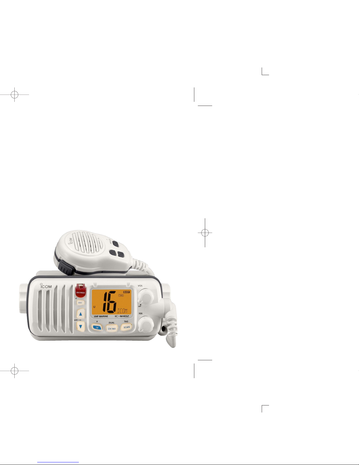
the IC-M402A/M402SA.
EXPLICIT DEFINITIONS
WORD DEFINITION
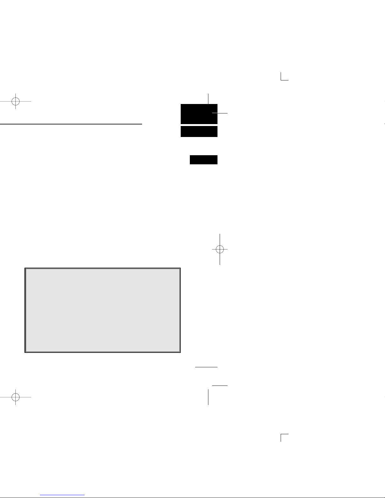
R WARNING!
CAUTION
NOTE
Personal injury, fire hazard or electric shock
may occur.
Equipment damage may occur.
Recommended for optimum use. No risk of
personal injury, fire or electric shock.
CLEAN THE TRANSCEIVER AND MICROPHONE THOROUGHLY WITH FRESH WATER after exposure to water
including salt water, otherwise, the keys and switches may
become inoperable due to salt crystallization.
Page 3
ii
NOTE
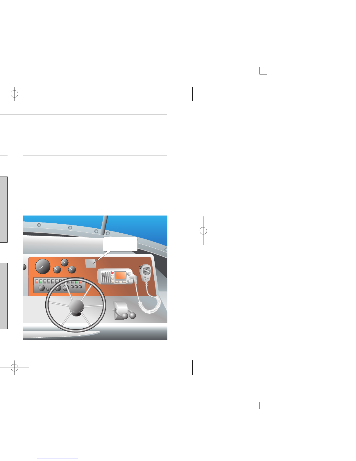
A WARNING STICKER is supplied with the transceiver.
To comply with FCC regulations, this sticker must be affixed in
such a location as to be readily seen from the operating controls of the radio as in the diagram below. Make sure the chosen location is clean and dry before applying the sticker.
(p. 33)
EXAMPLE
WARNING.
WARNING
STICKER
Page 4

FAILURE TO OBSERVE THESE LIMITS MAY ALLOW
THOSE WITHIN THE MPE RADIUS TO EXPERIENCE RF
RADIATION ABSORPTION WHICH EXCEEDS THE FCC
MAXIMUM PERMISSIBLE EXPOSURE (MPE) LIMIT.
IT IS THE RESPONSIBILITY OF THE RADIO OPERATOR
TO ENSURE THAT THE MAXIMUM PERMISSIBLE EXPOSURE LIMITS ARE OBSERVED AT ALL TIMES DURING
RADIO TRANSMISSION. THE RADIO OPERATOR IS TO
ENSURE THAT NO BYSTANDERS COME WITHIN THE
RADIUS OF THE MAXIMUM PERMISSIBLE EXPOSURE
LIMITS.
Determining MPE Radius
THE MAXIMUM PERMISSIBLE EXPOSURE (MPE) RADIUS HAS BEEN ESTIMATED TO BE A RADIUS OF
ABOUT 3M PER OET BULLETIN 65 OF THE FCC.
THIS ESTIMATE IS MADE ASSUMING THE MAXIMUM
POWER OF THE RADIO AND ANTENNAS WITH A MAXIMUM GAIN OF 9dBi ARE USED FOR A SHIP MOUNTED
SYSTEM.
Page 5

iv
……………………… 29
11 COMMANDMIC
®
HM-127
(IC-M402A only) ………………… 38–51
■ Panel description …………………38
■ Function display ……………………40
■ Channel selection …………………42
■ Receiving and transmitting ………43
■ Call channel programming ………44
■ Lock functions………………………44
■ Display backlighting ………………45
■ Monitor function ……………………45
■ Dualwatch/Tri-watch operation …45
■ Setting tag channels ………………46
■ Starting a scan ……………………46
■ Set mode programming …………47
■ Intercom operation…………………48
■ Channel comments ………………48
■ HM-127 supplied accessories ……49
■ Installation …………………………50
12 CHANNEL LIST …………………… 52
13 SPECIFICATIONS …………… 53–54
■ Specifications …………………… 53
■ Dimensions ……………………… 54
14 TEMPLATE ………………………… 55
15 OPTIONS …………………………… 57
Page 6

BE CAREFUL! The transceiver rear panel will become
hot when operating continuously for long periods.
Place the transceiver in a secure place to avoid inadvertent
use by children.
BE CAREFUL! The transceiver and optional HM-127*em-
ploy waterproof construction, which corresponds to JIS waterproof specification, Grade 7 (1 m/30 min.). However, once
the transceiver or microphone has been dropped, waterproofing cannot be guaranteed due to the fact that the case
may be cracked, or the waterproof seal damaged, etc.
*IC-M402A only
Page 7
1
1
OPERATING RULES
(2) OPERATOR’S LICENSE
A Restricted Radiotelephone Operator Permit is the license
most often held by small vessel radio operators when a radio
is not required for safety purposes.
The Restricted Radiotelephone Operator Permit must be
posted or kept with the operator. Only a licensed radio operator may operate a transceiver.
However, non-licensed individuals may talk over a transceiver
if a licensed operator starts, supervises, ends the call and
makes the necessary log entries.
Keep a copy of the current government rules and regulations
handy.
Radio license for boaters (U.S.A. only)
The Telecommunications Act of 1996 permits recreational
boaters to have and use a VHF marine radio, EPIRB, and
marine radar without having an FCC ship station license.
Boaters traveling on international voyages, having an HF
single sideband radiotelephone or marine satellite terminal, or required to carry a marine radio under any other
regulation must still carry an FCC ship station license. For
further information, see the FCC Ship Radio Stations Fact
Sheet.
1
Page 8

r SCAN KEY [SCAN•
TAG ] (p. 13)
➥ Starts and stops Normal or Priority scan.
➥ Sets or clears the displayed channel as a tag (scanned)
channel when pushed for 1 sec.
➥ While pushing [HI/LO] on the microphone, push for 3
sec. to clear or set all tag channels in the selected channel group.
t CHANNEL/WEATHER CHANNEL KEY [CH/WX•
DUAL]
➥ Toggles between regular channels and weather chan-
nel when pushed momentarily. (p. 7)
➥ Starts Dualwatch or Tri-watch when pushed for 1 sec.
(p. 11)
➥ Stops Dualwatch or Tri-watch when either is activated.
y CHANNEL 16/CALL CHANNEL KEY [16•
9]
➥ Selects Channel 16 when pushed. (p. 6)
➥ Selects call channel when pushed for 1 sec. (p. 6)
•“CALL” appears when call channel is selected.
➥ Push for 3 sec. to enter call channel programming con-
dition when call channel is selected. (p. 9)
➥ While pushing [CH/WX
•DUAL], push to enter the chan-
nel comments programming condition. (p. 10)
➥ Enters Set mode when pushed while turning power ON.
(p. 30)
Page 9

3
2
PANEL DESCRIPTION
2
Page 10

r TAG CHANNEL INDICATOR (p. 13)
Appears when a tag channel is selected.
t CALL CHANNEL INDICATOR (p. 6)
Appears when the call channel is selected.
y LOW POWER INDICATOR (p. 8)
Appears when low power is selected.
u DUPLEX INDICATOR (p. 7)
Appears when a duplex channel is selected.
i WEATHER CHANNEL INDICATOR (pgs. 7, 31)
➥ “WX” appears when a weather channel is selected.
➥ “WX ALT” appears when the Weather alert function is
in use; blinks when an alert tone is received.
o GPS INDICATOR
➥ Appears while valid position data is received.
➥ Blinks when invalid position data is received.
➥ Disappears when no GPS receiver is connected.
!0 DSC INDICATOR
Indicates the DSC status.
➥ “DSC” appears when a DSC call is received. (p. 25)
➥ “POS REPLY” appears when a Position Request Reply
call or Position Report Reply call is received. (p. 28)
Page 11
5
2
PANEL DESCRIPTION
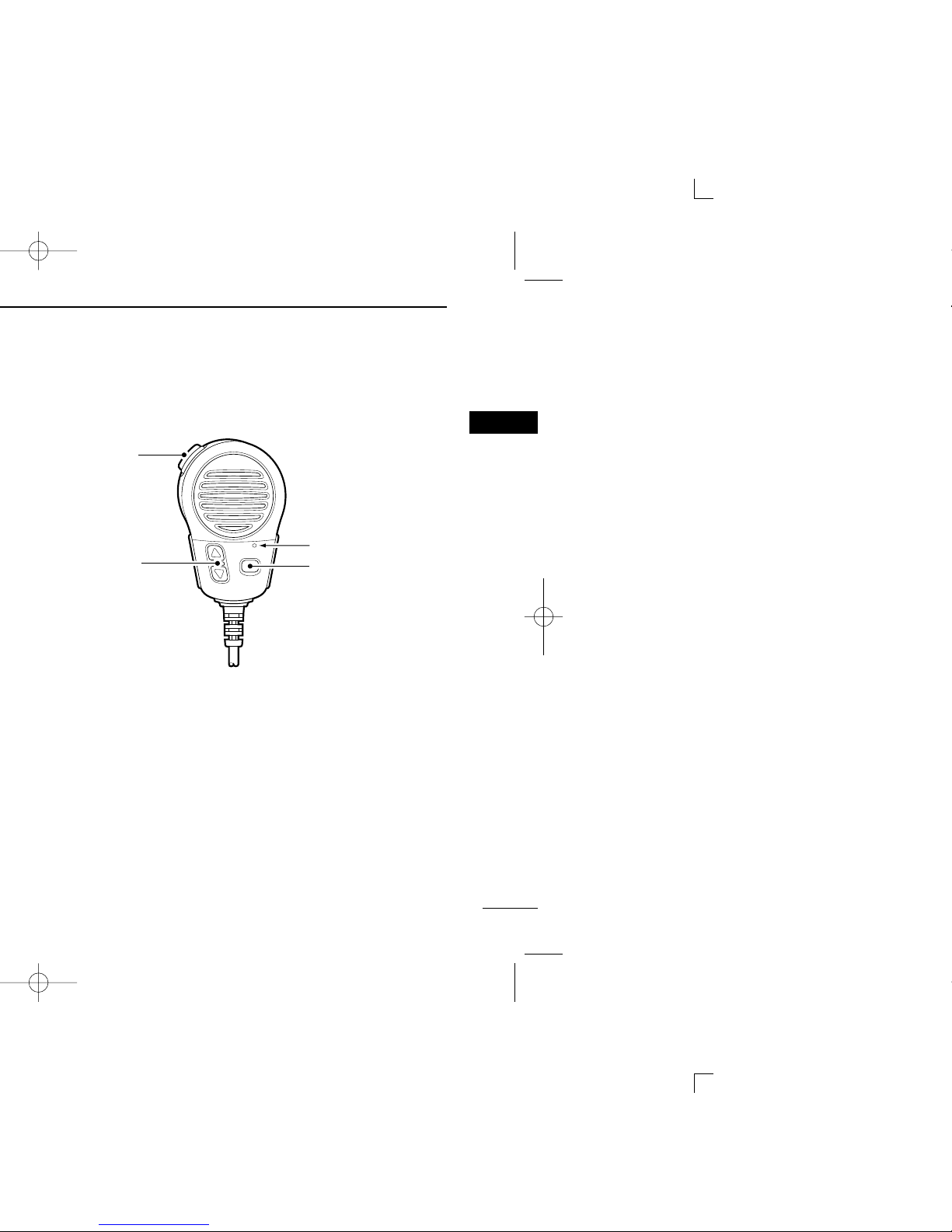
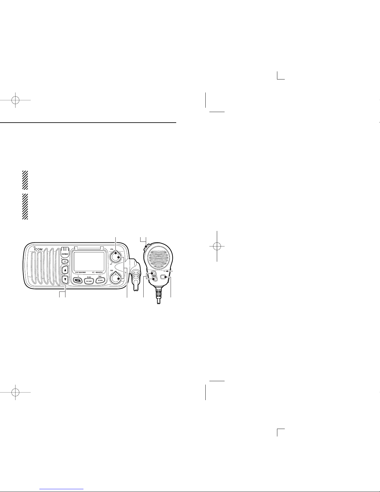
■ Microphone
q PTT SWITCH [PTT]
Push and hold to transmit; release to receive. (p. 8)
w CHANNEL UP/DOWN KEYS [YY]/[ZZ]
Push either key to change the operating memory channel,
Set mode settings, etc. (pgs. 6, 7, 30)
e TRANSMIT POWER KEY [HI/LO]
➥ Toggles power high and lower when pushed. (p. 8)
• Some channels are set to low power only.
➥ While pushing [HI/LO], turn power ON to toggle the mi-
crophone lock function ON and OFF. (p. 10)
Microphone
w
q
e
2
Page 12

ïï
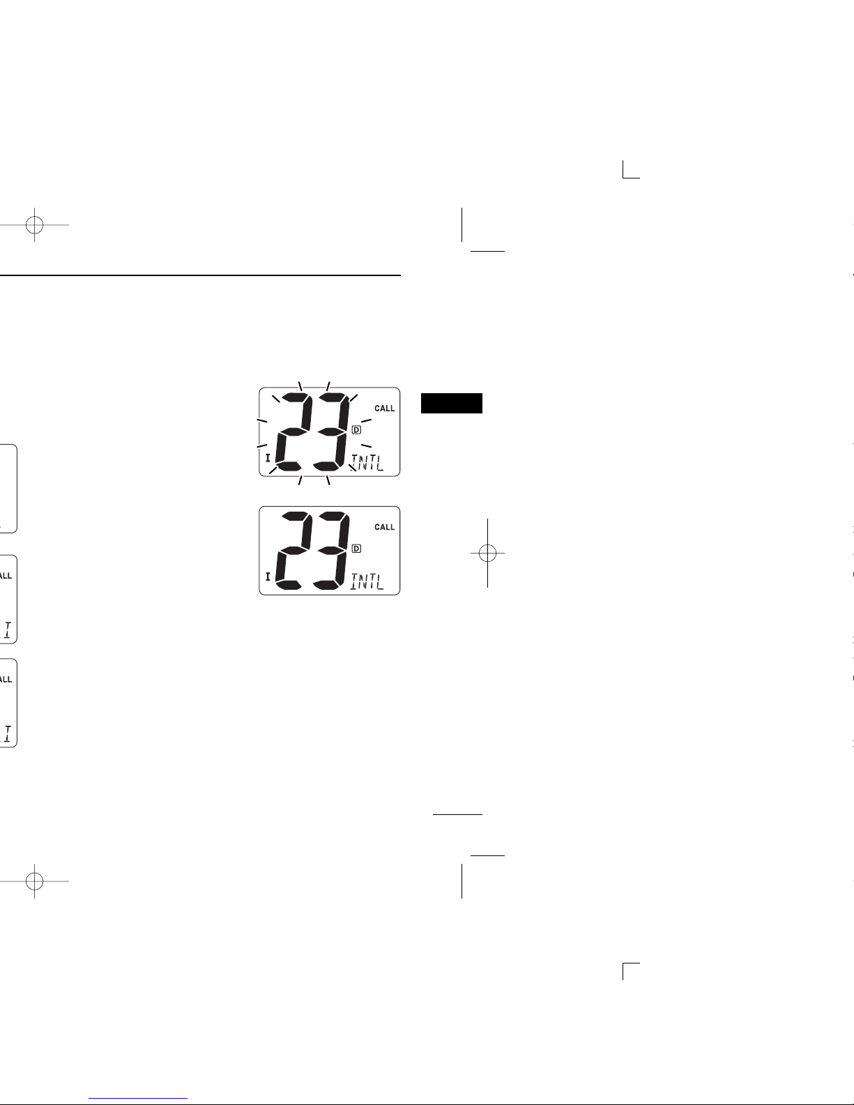
Channel 9 (Call channel)
Each regular channel group has a separate leisure-use call
channel. The call channel is monitored during Tri-watch. The
call channels can be programmed (p. 9) and are used to store
your most often used channels in each channel group for
quick recall.
➥ Push [16•
9] for 1 sec. to select the call channel of the se-
lected channel group.
•“CALL” and call channel number appear.
• Each channel group may have an independent call channel after
programming a call channel. (p. 9)
➥ Push [CH/WX•DUAL
] to return to the condition before se-
lecting call channel, or push [Y] or [Z] to select an operating channel.
Push
for 1 sec.
Scrolls
Page 13
7
3
BASIC OPERATION
ïï
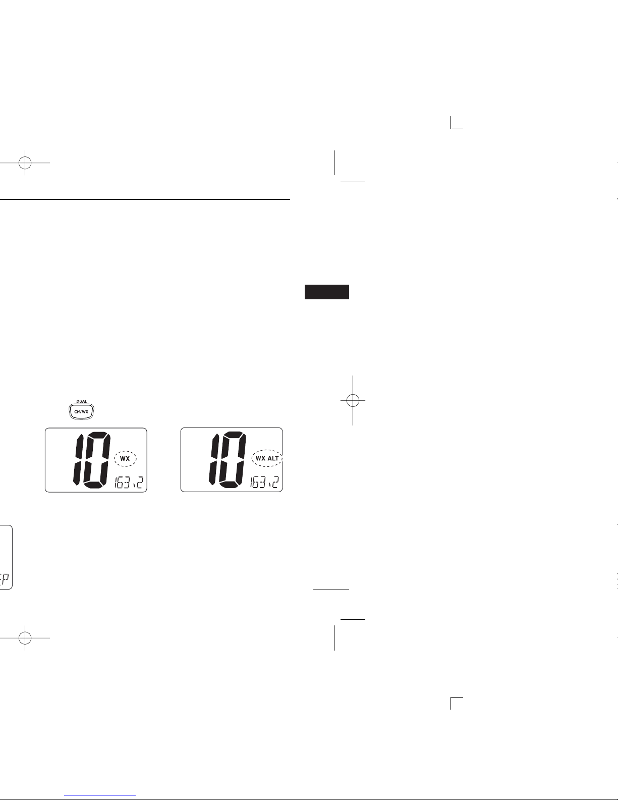
Weather channels
The IC-M402A/M402SA has 10 weather channels. These are
used for monitoring broadcasts from NOAA (National
Oceanographic and Atmospheric Administration.)
The transceiver can detect a weather alert tone on the selected weather channel while receiving the channel, during
standby on a regular channel or while scanning. (p. 31)
q Push [CH/WX•
DUAL] once or twice to select a weather
channel.
•“WX” appears when a weather channel is selected.
• “WX ALT” appears when the Weather alert function is in use.
(p. 31)
w Push [Y] or [Z] to select a channel.
Push once or twice
When Weather alert is OFF.
When Weather alert is ON.
3
Page 14
Simplex channels, 3, 21, 23, 61, 64, 81, 82 and 83 CANNOT be lawfully used by the general public in U.S.A. wa-
ters.
IMPORTANT: To maximize the readability of your trans-
mitted signal, pause a few sec. after pushing [PTT], hold
the microphone 2 to 4 inches (5 to 10 cm) from your mouth
and speak into the microphone (M) at a normal voice level.
u
rt
M
yq
M: Microphone
w
re
Page 15
9
3
BASIC OPERATION
r Push [Y] or [Z] to select
the desired channel.
t Push [16•
9] to program the
displayed channel as the
call channel.
• Push [CH/WX•DUAL] to can-
cel.
• The channel number stops
blinking.
3
Page 16

■ Microphone lock function
The microphone lock function electrically locks [Y]/[Z] and
[HI/LO] keys on the supplied microphone. This prevents ac-
cidental channel changes and function access.
➥ While pushing [HI/LO] on the microphone, turn power ON
to toggle the lock function ON and OFF.
■ Display backlighting
The function display and keys can be backlit for better visibility under low light conditions.
➥ While pushing [SCAN
•TAG], push [Y] or [Z] to adjust the
brightness of the LCD and key backlight.
• The backlight is selectable in 3 levels and OFF.
[HI/LO]
[Y]/[Z]
Page 17
11
4
DUALWATCH/TRI-WATCH
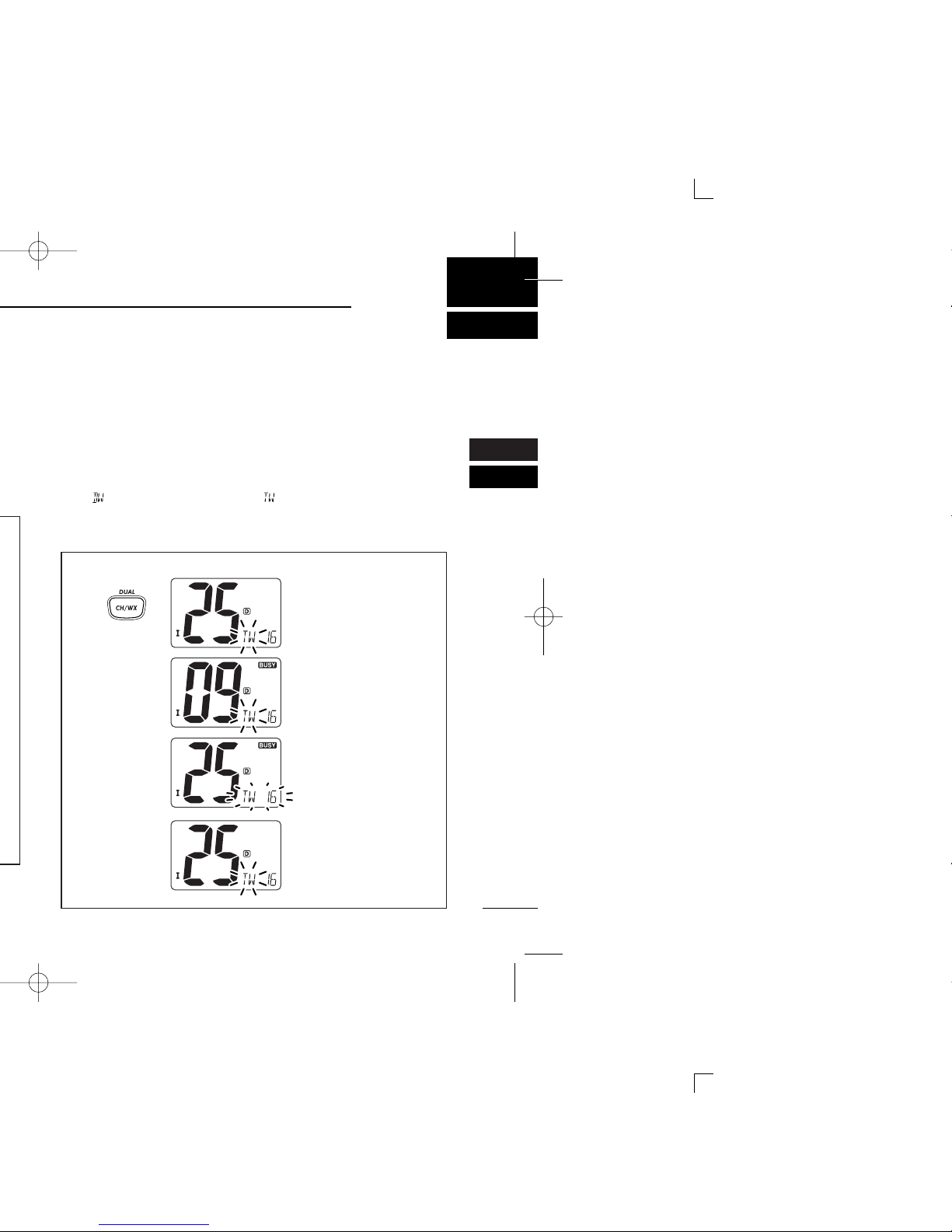
■ Operation
q Select Dualwatch or Tri-watch in Set mode. (p. 31)
w Select the desired operating channel.
e Push [CH/WX•
DUAL] for 1 sec. to start Dualwatch or Tri-
watch.
•“ ” blinks during Dualwatch; “” blinks during Tri-watch.
• A beep tone sounds when a signal is received on Channel 16.
r To cancel Dualwatch/Tri-watch, push [CH/WX•DUAL] again.
[Example]: Operating Tri-watch on INT Channel 25
Tri-watch starts.
Signal is received on call
channel.
Signal is received on
Channel 16 takes priority.
Tri-watch resumes after
the signal disappears.
Push
for 1 sec.
3
4
Page 18

Set the tag channels (scanned channel) before scanning.
Clear the tag channels which inconveniently stop scanning,
such as those for digital communication use.
Choose Priority or Normal scan in Set mode. (p. 31)
NORMAL SCAN
Normal scan, like Priority scan, searches through all tag
channels in sequence. However, unlike priority scan, Channel 16 is not checked unless Channel 16 is set as a tag
channel.
CH 01 CH 02
CH 06
CH 05 CH 04
CH 03
Page 19
13
5
SCAN OPERATION
■ Starting a scan
Set scan type (Priority or Normal) and scan resume timer in
advance, using Set mode. (p. 31)
q Set tag channels as described at left.
w Make sure the squelch is closed to start a scan.
e Select the channel group (USA, CAN, INT) by pushing
both [Y] and [Z] on the transceiver, if desired.
r Push [SCAN•
TAG ] to start Priority or Normal scan.
•“ ” or “” appears at the channel comment indicator.
• When a signal is detected, scan pauses until the signal disap-
pears or resumes after pausing 5 sec. according to Set mode
setting. (Channel 16 is still monitored during Priority scan.)
• Push [Y] or [Z] to check the scanning tag channels, to change
the scanning direction or resume the scan manually.
•“ ” blinks at the channel comment indicator and a beep tone
sounds when a signal is received on Channel 16 during Priority
scan.
t To stop the scan, push [SCAN•TAG].
Scan starts. When a signal is received.
Push
5
Page 20

■ MMSI code check
The 9-digit MMSI (DSC self ID) code can be checked.
q Push [DSC•
IC] to enter the DSC menu.
w Push [Y] or [Z] to select “” and push [DSC•
IC].
e Check the 9-digit MMSI (DSC self ID) code.
• The MMSI code is displayed and scrolls at the channel comment
indicator.
r Push [DSC•IC] to exit the DSC menu.
MMSI (DSC self ID) code scrolls
Page 21

15
6
DSC OPERATION
r Push [Y] or [Z] to input 9-digit of the appropriate Individ-
ual/Group ID.
• Push [SCAN•TAG] or [CH/WX•DUAL] to move the cursor forward
or backward, respectively.
• Push [16•9] to cancel and exit the condition.
1st digit ‘0’ is fixed for a group ID. Thus an address ID input
cannot start with ‘0.’ When you input 1st digit ‘0’ and other 8
digits, the ID is automatically registered as a group ID.
t After inputting 9-digit ID, push [DSC•IC] to input 5 charac-
ters ID name using [Y] or [Z].
• Push [SCAN•TAG] or [CH/WX•DUAL] to move the cursor forward
or backward, respectively.
• Push [16•9
] to cancel and exit the condition.
y Push [DSC•IC] to program and exit the DSC menu.
6
Page 22

■ Position indication
When a GPS receiver (NMEA0183 ver. 2.0 or 3.01) is connected, the transceiver indicates the current position data in
seconds of accuracy.
A NMEA0183 ver. 2.0 or 3.01 (sentence formatters RMC,
GGA, GNS, GLL) compatible GPS receiver is required. Ask
your dealer about suitable GPS receivers.
➥ While pushing [SCAN
•TAG ], push [DSC•IC] to display the
current position.
•‘Latitude’ and ‘Longitude’ scroll in sequence at the channel com-
ment indicator.
• “” scrolls when no GPS is connected.
• When the connecting GPS receiver is compatible with
several sentence formatters, the order of input precedence is ‘RMC,’‘GGA,’‘GNS’ and ‘GLL.’
• “GPS” blinks when the GPS data is invalid.
Scrolls
Page 23

17
6
DSC OPERATION
r After receiving the acknowledgment, reply using the mi-
crophone.
•“ ” scrolls at the channel comment indicator.
➥ A distress alert contains;
• Kinds of distress: Undesignated distress
• Position data : Latest GPS position data held for 23.5 hrs.
or until the power is turned OFF.
➥ The Distress call is repeated every 3.5–4.5 min., until re-
ceiving an ‘acknowledgement.’
➥ Push [DISTRESS] to transmit a renewed Distress call,
if desired.
➥ Push any key except [DISTRESS] to cancel the ‘Call
repeat’ mode.
Scrolls
Scrolls
6
Page 24

e Push [Y] or [Z] to specify the desired intership channel,
and push [DSC•
IC].
• Channel 70 is selected and “” appears.
r Push [DSC•IC] to transmit the Individual call.
• If Channel 70 is busy, the transceiver stands by until the channel
becomes clear.
• Routine category only is available.
When Ch 70 is busy.Push [DSC
IC] to
transmit DSC call.
Page 25

19
6
DSC OPERATION
D Transmitting Individual acknowledgement
Transmit an acknowledgement (‘able to comply’ or ‘unable to
comply’) when an Individual call for you is received.
q Push [DSC•
IC] to enter the DSC menu.
w Push [Y] or [Z] to select “” and push [DSC•
IC].
• “” item appears after an Individual call is received.
• “” item disappears if another call is received after the
Individual call.
• The Individual acknowledgement can be transmitted to the last
received individual call only.
e Push [Y] or [Z] to select the acknowledgement “” or
“ .”
Scrolls
6
Page 26

D Transmitting Group call
The Group call function allows you to transmit a DSC signal
to a specific group only.
q Push [DSC•
IC] to enter the DSC menu.
w Push [Y] or [Z] to select “ ,” and push [DSC•
IC].
e Push [Y] or [Z] to select the desired pre-programmed
group address, and push [DSC•
IC
].
• The ID code for the group call must be set in advance. (p. 15)
Page 27

21
6
DSC OPERATION
y After the Group call has been transmitted, the display
changes to the previously specified channel.
u Push and hold [PTT] to communicate your message to the
responding ship.
6
Page 28

r Push [DSC•IC] to transmit the All Ships call.
• Routine category only is available.
t After the All Ships call has been transmitted, the display
changes to Channel 16 automatically.
Scrolls
Page 29

23
6
DSC OPERATION
r Push [DSC•IC] to enter the standby condition for Position
Request call.
• Channel 70 is selected and “” appears.
t Push [DSC•IC] to transmit the Position Request call.
y After the Position Request call has been transmitted, the
following indication is displayed.
•“ ” scrolls at the channel comment indicator.
u Push any key to exit the condition and return to the nor-
mal operation.
Scrolls
6
Page 30

r Push [DSC•IC] to enter the standby condition for Position
Report call.
• Channel 70 is selected and “” appears.
t Push [DSC•IC] to transmit the Position Report call.
y After the Position Report call has been transmitted, stand
by on Channel 70 until an acknowledgement is received.
•“ ” scrolls at the channel comment indicator.
u Push any key to exit the condition and return to the nor-
mal operation.
Scrolls
Page 31

25
6
DSC OPERATION
D Receiving a Distress acknowledgement
While monitoring Channel 70 and a Distress acknowledgement to other ship is received:
➥ The emergency alarm sounds for 2 minutes.
• Push any key to stop the alarm.
➥ “DSC” appears and “” scrolls at the chan-
nel comment indicator, then Channel 16 is automatically
selected.
D Receiving a Distress Relay call
While monitoring Channel 70 and a Distress Relay acknowledgement is received:
➥ The emergency alarm sounds for 2 minutes.
• Push any key to stop the alarm.
➥ “DSC” appears and “” scrolls at the channel com-
ment indicator, then Channel 16 is automatically selected.
Scrolls
Scrolls
6
Page 32

D Receiving a Group call
While monitoring Channel 70 and a Group call is received:
➥ The emergency alarm or beeps sound depending on the
received category.
➥ “DSC” appears and “” scrolls at the channel
comment indicator.
➥ Push [DSC•
IC] to change to the channel specified by the
calling station for voice communication; push any other key
to ignore the Group call.
Scrolls
Page 33

27
6
DSC OPERATION
D Receiving a Geographical Area call
While monitoring Channel 70 and a Geographical Area call
(for the area you are in) is received:
➥ The emergency alarm or beeps sound depending on the
received category.
➥ “DSC” appears and “” scrolls at the chan-
nel comment indicator.
➥ Push [DSC•
IC
] to change to the channel specified by the
calling station for voice communication; push any other key
to ignore the Geographical Area call.
➥ Monitor the selected channel for an announcement from
the calling station.
When no GPS receiver is connected or if there is a problem with the connected receiver, all Geographical Area
calls are received, regardless of your position.
Scrolls
6
Page 34

D Receiving a Position Report call
While monitoring Channel 70 and a Position Report call is received:
➥ “DSC” appears and “” scrolls at the chan-
nel comment indicator.
➥ Push [DSC•
IC] to reply to the Position Report call; push
any other key to ignore the Position Report call.
D Receiving a Position Report Reply call
While monitoring Channel 70 and a Position Report Reply call
is received:
➥ “DSC” and “POS REPLY” appear in the display.
• The ‘Latitude’ and ‘Longitude’ you have sent is displayed and
scrolled automatically in order of Latitude co-ordinates and then
Longitude co-ordinates.
Scrolls
Scrolls
Page 35

29
7
6
7
r After releasing the PTT switch you can hear the response
through the speaker.
t To return to the normal operation, push [DSC•
IC] momen-
tarily.
• Other keys also turn the function OFF, however, the corresponding function is then activated (e.g. pushing [16•9]selects Channel 16).
• While in the Intercom mode, the transceiver functions
(transmit and receive) are interrupted. If the transceiver
is in transmit condition, the Intercom function is not available.
• When a DSC call is received, “DSC” appears and DSC
message is displayed at the channel comment indicator
after the Intercom use is finished.
• When a WX alert is received, “WX ALT” blinks and a
beep sounds. The WX alert sounds after the Intercom
use is finished.
IC-M402A (caller)
INT
HM-127 (listener)
Page 36

D Set mode operation
q Turn power OFF.
w While pushing [16•
9], turn power ON to enter Set mode.
• “” appears at the channel comment indicator.
e After the display appears, release [16•9].
r Push [16•
9] to select the desired item, if necessary.
t Push [Y] or [Z] to select the desired condition of the item.
y Turn power OFF, then ON again to exit Set mode.
Dual/Tri-watch DSC watch
Push
Scrolls
Page 37

31
8
SET MODE
DD
Weather alert
A NOAA broadcast station transmits a weather alert tone before important weather information. When the weather alert
function is turned ON, the transceiver detects the alert, then
the “WX ALT” indicator blinks until the transceiver is operated.
The previously selected (used) weather channel is checked
any time during standby or while scanning.
•“WX ALT” appears instead of “WX” indication when the function is
set ON.
DD
Dual/Tri-watch
This item can be selected as Dualwatch or Tri-watch. (p. 11)
Dualwatch (default) Tri-watch
Weather alert OFF (default) Weather alert ON
8
Page 38

DD
LCD contrast
This item adjusts the contrast of the LCD in 4 levels.
The LCD contrast can be adjustable in 4 levels. 1 is the lowest contrast, and 4 is the highest contrast.
DD
Automatic acknowledgement
This item sets the Automatic acknowledgement function ON
or OFF.
When Position Request or Position Report call is received,
transceiver automatically transmits Position Request Reply or
Position Report Reply, respectively.
•
“” scrolls at the channel comment indicator.
Auto acknowledgement
OFF (default)
Auto acknowledgement
ON
Scrolls Scrolls
LCD contrast level 3
(default)
LCD contrast level 1
Page 39

33
9
■ Antenna
A key element in the performance of any communication system is the antenna. Ask your dealer about antennas and the
best place to mount them.
■ Fuse replacement
One fuse is installed in the supplied DC power cable. If a fuse
blows or the transceiver stops functioning, track down the
source of the problem, if possible, and replace the damaged
fuse with a new, rated one.
■ Cleaning
If the transceiver becomes dusty or dirty, wipe it clean with a
soft, dry cloth.
AVOID the use of solvents such as benzene or alcohol, as they may damage transceiver surfaces.
8
9
Page 40

-
r GPS RECEIVER JACK
Connects to a GPS receiver for position indication.
• A NMEA0183 ver. 2.0 or 3.01 (sentence formatters RMC, GGA,
GNS, GLL) compatible GPS receiver is required. Ask your dealer
about suitable GPS receivers.
t EXTERNAL SPEAKER JACK
Connects to an external speaker. See p. 57 for available
external speakers.
CAUTION: After connecting the DC power cable, GPS receiver jack and external speaker jack, cover the connector
and jacks with an adhesive tape as shown below, to prevent water seeping into the transceiver.
Rubber vulcanizing
tape
NMEA (+)
RCA
NMEA (—)
Page 41

35
9
CONNECTIONS AND MAINTENANCE
■ Optional MB-92 attachment
An optional MB-92
DUST COVER
is available for attaching the
transceiver’s front panel to prevent the keys and knobs getting wet when the transceiver is not used.
➥ Attach the optional MB-92
DUST COVER
to the transceiver
as shown below.
9
Page 42

e Attach the clamps on either side of the transceiver with 2
supplied bolts (5 × 8 mm).
• Make sure that the clamps align parallel to the transceiver body.
r Tighten the end bolts on the clamps (rotate clockwise) so
that the clamps press firmly against the inside of the instrument control panel.
t Tighten the locking nuts (rotate counterclockwise) so that
the transceiver is securely mounted in position as below.
y Connect the antenna and power cable, then return the in-
strument control panel to its original place.
IC-M402A
Page 43

37
10
TROUBLESHOOTING
p. 8
p. 8
—
• Set squelch to the threshold point.
• Set [VOL] to a suitable level.
• Drain water from the speaker.
pgs. 6,
7, 52
p. 8
• Change channels.
• Push [HI/LO] on the microphone to select
high power.
• Turn the beep tone ON in Set mode.
• Set squelch to the threshold point.
p. 32
p. 8
• Program the MMSI (DSC self ID) code. p. 14
9
10
Page 44

q PTT SWITCH [PTT] (pgs. 8, 43)
Push and hold to transmit; release to receive.
w CHANNEL UP/DOWN KEYS [YY]/[ZZ]
➥ Push either key to change the operating channel, Set
mode settings, etc. (pgs. 8, 30, 43, 47)
➥ Push either key to adjust audio level or noise squelch
level after [VOL] or [SQL] is pushed, respectively.
(pgs. 8, 43)
➥ Push either key to adjust the brightness of the LCD and
key backlight after [VOL• ] is pushed for 1 sec.
(p. 45)
➥ Checks tag channels or changes scanning direction dur-
ing scan. (pgs. 13, 46)
e CHANNEL 16/CALL CHANNEL KEY [16•
9]
➥ Selects Channel 16 when pushed. (pgs. 6, 42)
➥ Selects call channel when pushed for 1 sec. (pgs. 6, 42)
•“CALL” appears when call channel is selected.
➥ Push for 3 sec. to enter call channel programming con-
dition when call channel is selected. (pgs. 9, 44)
➥ While pushing [CH/WX•
U/I/C], enters channel com-
ments programming condition. (pgs. 10, 48)
➥ Enters Set mode when pushed while turning power ON.
(pgs. 30, 47)
DW
DIM
OPTION
(IC-M402A only)
Page 45

39
11
COMMANDMIC®HM-127
y SQUELCH/MONITOR/LOCK KEY [SQL•
L]
➥ [YY]/[ZZ] sets the squelch threshold level after pushing
[SQL]. (p. 43)
➥ Push [SQL•
L] for 1 sec. to turn the monitor func-
tion ON. (p. 45)
➥ While pushing [H/L], push [SQL•
L] to toggle the
(microphone) Key lock function ON or OFF. (p. 44)
•“ T ” appears while (microphone) Key lock function is in use.
• [PWR], [PTT], [VOL], [SQL] and [H/L] still function when the
(microphone) Key lock function is turned ON.
➥ Advance the cursor while in channel comment pro-
gramming condition. (pgs. 10, 48)
u VOLUME/DIMMER KEY [VOL• ]
➥ [YY]/[ZZ] adjusts the audio level after pushing [VOL]
(p. 43)
➥ [YY]/[ZZ] adjust the brightness of the LCD and key back-
light after pushing [VOL• ] for 1 sec. (p. 45)
➥ Move the cursor backward while in channel comment
programming condition. (pgs. 10, 48)
DIM
DIM
MONI
MONI
MONI
11
Page 46

■ Function display
q CHANNEL GROUP INDICATOR (pgs. 7, 42)
Indicates whether an International “INT,” U.S.A. “USA” or
Canadian “CAN” channel is selected.
w KEY LOCK INDICATOR (p. 44)
➥ Appears while the Key lock function is in use.
➥ Blinks while the All key lock function is in use.
e CHANNEL NUMBER READOUT
➥ Indicates the selected operating channel number.
“A” appears when a simplex channel is selected. “b” appears when a receive only channel for a Canadian
channel group is selected. (pgs. 6, 42)
➥ In Set mode, indicates the selected condition.
(pgs. 30, 47)
CALL
WX ALT
DUP
P SCAN TRI
DUAL
LOW
TAG
CAN
USA
INT
L
TX
BUSY
VOL
SQL
q
w
r
t
e
!4!5 !3
!2
!1
!0
u
i
o
y
!6
Page 47

41
11
COMMANDMIC®HM-127
o DUAL/TRI-WATCH INDICATOR (pgs. 11, 45)
“DUAL” appears during Dualwatch; “TRI” during Tri-watch.
!0 WEATHER CHANNEL INDICATOR (pgs. 7, 42)
➥ “WX” appears when a weather channel is selected.
➥ “WX ALT” appears when the Weather alert function is
in use; blinks when an alert tone is received.
!1 LOW POWER INDICATOR (pgs. 8, 43)
Appears when low power is selected.
!2 CALL CHANNEL INDICATOR (pgs. 6, 42)
Appears when call channel is selected.
!3 DUPLEX INDICATOR (pgs. 7, 42)
Appears when a duplex channel is selected.
!4 TAG CHANNEL INDICATOR (pgs. 13, 46)
Appears when a tag channel is selected.
!5 BUSY INDICATOR (pgs. 8, 43, 45)
Appears when receiving a signal or when the squelch
opens.
!6 TRANSMIT INDICATOR (pgs. 8, 43)
Appears while transmitting.
11
Page 48

DD
U.S.A., International and Canadian channels
q Push [CH/WX• U/I/C] to select a regular channel.
• Push [CH/WX• U/I/C] again, if a weather channel appears.
w While pushing [H/L], push [CH/WX• U/I/C] to select a
channel group.
• U.S.A., International and Canadian channels can be selected in
sequence.
U.S.A. channels
Canadian channelsInternational channels
+
while pushing
Push
+
DW
DW
DW
Page 49

43
11
COMMANDMIC®HM-127
IMPORTANT: To maximize the readability of your trans-
mitted signal (voice), pause a few sec. after pushing [PTT],
hold the microphone 2 to 4 inches (5 to 10 cm) from your
mouth and speak at a normal voice level.
w Set volume
w Set squelch,
if required
r Set output power
t Speak into
microphone
q Turn power ON
e Set channel
t Push to
transmit
y Release
to receive
11
Page 50

■ Lock functions
The Lock function electronically locks keys and switches to
prevent accidental changes and function access from the microphone.
• All keys, switches and controllers on the transceiver are functional.
DD
Activating the Lock function
➥ While pushing [H/L], push
[SQL•
L] to turn the Lock
function ON or OFF.
•“ ” appears.
• Only [PWR], [PTT], [H/L],
[SQL• L
], [VOL]+[YY]/[ZZ]
and [SQL]+[YY]/[ZZ] are functional.
DD
Activating the All key lock function
➥ While pushing [H/L], turn the
power ON by pushing [PWR]
to turn the All key lock function
ON or OFF.
•“ ” blinks.
• Only [PWR] and [PTT] are func-
tional.
MONI
MONI
Appears when the lock
function is in use.
Blinks when the all lock
function is in use.
Page 51

45
11
COMMANDMIC®HM-127
■ Dualwatch/Tri-watch operation
q Push [YY] or [ZZ] to select the desired channel.
• Push [CH/WX• U/I/C] several times while pushing [H/L] to
select the channel group (USA, INT, CAN), if desired.
w Push [CH/WX• U/I/C] for 1 sec. to start Dualwatch or
Tri-watch.
•“DUAL” appears during Dual-
watch; “TRI” appears during Triwatch.
• A beep tone sounds when a signal is received on Channel 16.
• Tri-watch becomes Dualwatch
when receiving a signal on call
channel.
• Dualwatch or Tri-watch can be
selected in the transceiver’s Set
mode.
e To cancel Dualwatch/Tri-watch, push [CH/WX• U/I/C
]
again.
DW
DW
DW
Appears when the Dual or
Tri-watch function is in use.
11
Page 52

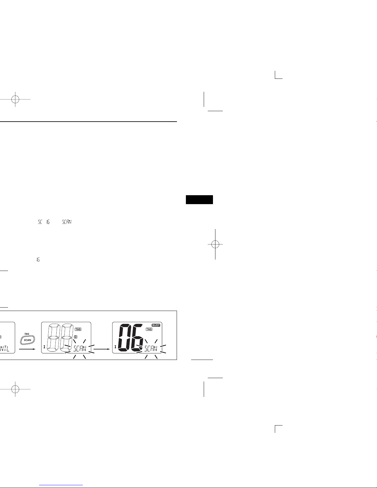
■ Starting a scan
q While pushing [H/L], push [CH/WX• U/I/C] several
times to select the channel group (USA, INT, CAN), if desired.
• When the Weather alert function is in use, select the desired
weather channel with [CH/WX• U/I/C] and [YY] or [ZZ].
w Push [SCAN• ] to start Priority or Normal scan.
•“SCAN” appears during Normal scan.
• The priority channel readout indicates “16”, and “P” and “SCAN”
indicators appear during Priority scan.
• When a signal is received, scan pauses until the signal disappears or resumes after pausing 5 sec. according to the Set mode
setting (Channel 16 is still monitored during Priority scan).
• Push [YY] or [ZZ] to check the scanning tag channels, to change
the scanning direction or resume the scan manually.
e To stop the scan, push [SCAN• ].
•“SCAN” disappears.
• Pushing [PTT], [16•9] or [CH/WX• U/I/C] also stops the scan.
DW
TAG
TAG
DW
DW
Page 53

47
11
COMMANDMIC®HM-127
DD
Entering Set mode
q Turn power OFF.
w While pushing [16•
9], turn power ON.
• After a beep emission, a set mode item (in the channel comment
indicator and the condition in the channel number readout) is displayed.
e Push [16•9] to select the desired item, if necessary.
r Push [YY] or [ZZ] to select the desired condition of the item.
t Turn power OFF, then ON to exit Set mode.
• Beep tone “”
➥ Push [YY] to turn ON, [ZZ] to turn OFF the beep output.
• LCD contrast “”
➥ Push [YY]/[ZZ] to adjust to a suitable LCD contrast.
•
“” scrolls at the channel comment indicator.
Push
Scrolls
Scrolls
Push
11
Page 54

■ Channel comments
q Push [YY] or [ZZ] to select a channel to program a channel
comment.
• Push [CH/WX• U/I/C] several times while pushing [H/L] to se-
lect the channel group (USA, INT, CAN), if desired.
w While pushing [CH/WX• U/I/C], push [16•9].
• The 1st character of the currently programmed comment blinks.
e Push [YY] or [ZZ] to select a character.
r Push [SQL] to move to forward; then push [YY] or [ZZ] to
select a character.
• Push [VOL] to move to backward.
t Repeat steps e and r to input all characters, then push
[16•
9] to return to normal operation.
• Available characters
(r)
(s) (t) (u) (v) (w) (x) (y) (z)
(q)
(3)
(D)
(N)
(X)
(h)
(+)
(4)
(E)
(O)
(Y)
(i)
(5)
(F)
(P)
(Z)
(j)
(✱)
(6)
(G)
(Q)
(a)
(k)
(/)
(7)
(H)
(R)
(b)
(l)
(,)
(8)
(I)
(S)
(c)
(m)
(space)
(9)
(T)
(d)
(n)
(0)
(A)
(U)
(e)
(o)
(1)
(B)
(V)
(f)
(p)
(2)
(C)
(J) (K) (L)
(M)
(W)
(g)
(.)
( ))(( )(&)(%)($)(#)(")(!) ( )
( )
DW
DW
Page 55

49
11
COMMANDMIC®HM-127
11
Page 56

w To use the supplied cable as a wall socket, follow the
below steps.
e Using the mounting base, carefully mark off the 2 spots
where the cable and screws will be fastened.
r Drill holes at these marks.
t Install the mounting base using the supplied screws as
shown below.
y The completed installation should look like this.
Gasket
Cap
Mounting base
Nut
Screw holes
(approx. 2 (d) mm;
3
32″)
Page 57

51
11
COMMANDMIC®HM-127
50 (d) mm; 1
31
⁄32˝
5 mm; 3⁄16˝
Cap
Nut
11
Page 58

New2001New2001
Channel number
66A
Frequency (MHz)
66A
*1
USA CAN
Transmit
Receive
64A 64A 156.225 160.825
65A 65A 156.275 156.275
156.325 160.925
67
*2
67 156.375 156.375
68 68 156.425 156.425
69 69 156.475 156.475
70
*3
70
*3
156.525 156.525
71 71 156.575 156.575
72 72 156.625 156.625
73 73 156.675 156.675
74 74 156.725 156.725
77
*1
77
*1
156.875 156.875
156.925 161.525
78A 78A 156.925 156.925
156.975 161.575
79A 79A 156.975 156.975
157.025 161.625
80A 80A 157.025 157.025
157.075 161.675
81A 81A 157.075 157.075
157.125 161.725
82A 82A 157.125 157.125
INT
65A
66
67
68
69
70
*3
71
72
73
74
77
78
79
80
81
82
156.325 156.32566A
Channel number
84A
Frequency (MHz)
USA CAN
Transmit
Receive
83A 83A 157.175 157.175
84 84 157.225 161.825
85 85 157.275 161.875
85A 157.275 157.275
86 86 157.325 161.925
86A 157.325 157.325
87 87 157.375 161.975
87A 157.375 157.375
88 88 157.425 162.025
88A 157.425 157.425
INT
84
85
86
87
88
157.225 157.225
WX channel
4
Frequency (MHz)
Transmit Receive
1 RX only 162.550
2 RX only 162.400
3 RX only 162.475
5 RX only 162.450
6 RX only 162.500
7 RX only 162.525
8 RX only 161.650
9 RX only 161.775
10 RX only 163.275
RX only 162.425
156.275 160.87565
83 157.175 161.77583
83b Rx only 161.775
NOTE: Simplex channels, 3, 21, 23, 61, 64, 81, 82 and 83 CANNOT
be lawfully used by the general public in U.S.A. waters.
Page 59

53
13
SPECIFICATIONS
DD
Receiver
• Receive system : Double conversion
superheterodyne
• Sensitivity (12 dB SINAD) : 0.22µV (typical)
• Squelch sensitivity : 0.22µV
• Intermodulation rejection ratio : More than 70 dB
•
Spurious response rejection ratio
: More than 70 dB
• Adjacent channel selectivity : More than 70 dB
• Audio output power : 4.5W (typical) at 10% distortion
with a 4 Ω load
All stated specifications are subject to change without notice or
obligation.
13
Page 60

Unit: mm (inch)
32.1 (1
1
4)
86.5 (3
13
32)
51 (2)
Page 61

55
14
TEMPLATE
13
14
Unit: mm (inch)
1
32
)
15
32
)
67 (2
5
8
)
53 (2
3
32
)
MB-69
2 (
3
32
)
Page 62

New2001
Page 63

57
15
OPTIONS
15
Page 64

1-1-32 Kamiminami, Hirano-ku, Osaka 547-0003, Japan
 Loading...