

Page 1
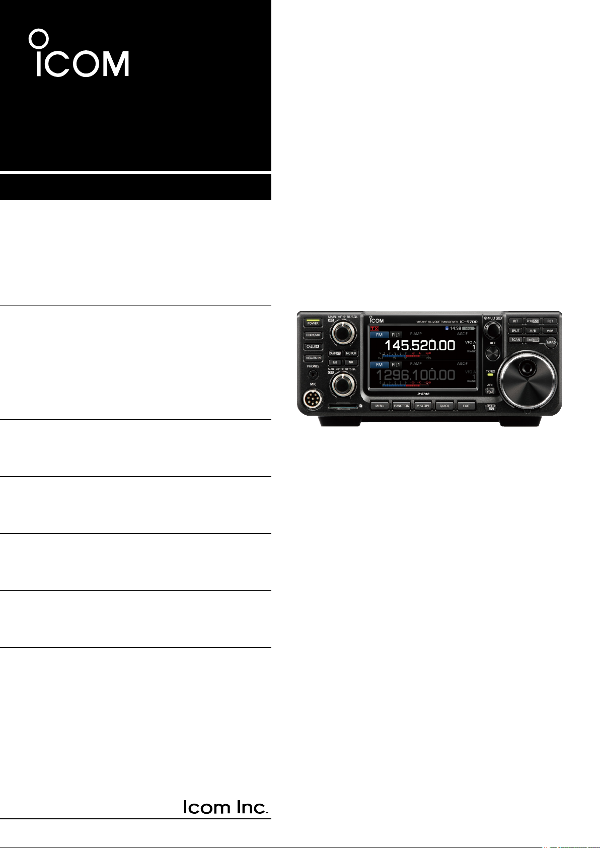
BASIC MANUAL
VHF/UHF ALL MODE TRANSCEIVER
|9700
Page 2

Thank you for choosing this Icom product. The IC-9700 VHF/UHF ALL MODE TRANSCEIVER is designed and built
with Icom’s state of the art technology and craftsmanship. With proper care, this product should provide you with
years of trouble-free operation. We appreciate you making the IC-9700 your transceiver of choice, and hope you
agree with Icom’s philosophy of “technology rst.” Many hours of research and development went into the design
of your IC-9700.
EXPLICIT DEFINITIONSIMPORTANT
READ ALL INSTRUCTIONS carefully completely
before using the transceiver.
SAVE THIS INSTRUCTION MANUAL— This
instruction manual contains basic operating
instructions for the IC-9700
. For advance operating
instructions, see the Advanced Manual for details.
The Advance Manual is available at the following
internet address:
http://www.icom.co.jp/world/support/
FEATURES
• RF Direct Sampling System
The IC-9700 employs an RF direct sampling system. RF
signals are directly converted to digital data in the ADC,
and then processed in the FPGA. This system is a leading
technology, marking an epoch in amateur radio.
The 1200 MHz band uses a downconversion IF sampling.
• Real-Time Spectrum Scope
The spectrum scope is class-leading in resolution,
sweep speed and dynamic range. When you touch the
scope screen on the intended signal, the touched area is
magnied. The large 4.3 inch color TFT touch LCD offers
intuitive operation.
• D-STAR operation
The IC-9700 has the D-STAR Repeater (DR) function.
Moreover, by using the DD mode, you can browse the
Internet through a repeater station.
• Satellite operation
The IC-9700 has 99 satellite memory channels for both
uplink and downlink frequencies and mode.
• “IP+” Function
The IP Plus function improves 3rd order intercept point
(IP3) performance. When a weak signal is received
adjacent to strong interference, the AD converter is
optimized against signal distortion.
• A 4.3 inch touch panel color display
• Multi-function control for easy settings
WORD DEFINITION
R DANGER!
R WARNING!
CAUTION
NOTE
Personal death, serious injury or an
explosion may occur.
Personal injury, fire hazard or electric
shock may occur.
Equipment damage may occur.
Recommended for optimum use. No
risk of personal injury, fire or electric
shock.
SUPPLIED ACCESSORIES
Spare fuse
(5 A)
Hand microphone
CW key plug
(3.5 mm: 1/8" Stereo)
L Different types of accessories may be supplied, or may
not be supplied depending on the transceiver version.
DC power cable
(3 m: 9.8 ft)
This product includes RTOS “RTX” software, and is
licensed according to the software license.
This product includes “zlib” open source software,
and is licensed according to the open source
software license.
This product includes “libpng” open source software,
and is licensed according to the open source
software license.
Spare fuse
(25 A)
Refer to the “About the Licenses” page at the end
of this manual for information on the open source
software being used in this product.
i
Page 3
FCC INFORMATION
ABOUT CE AND DOC
This equipment has been tested and found to comply
with the limits for a Class B digital device, pursuant
to part 15 of the FCC Rules. These limits are
designed to provide reasonable protection against
harmful interference in a residential installation. This
equipment generates, uses and can radiate radio
frequency energy and, if not installed and used in
accordance with the instructions, may cause harmful
interference to radio communications. However, there
is no guarantee that interference will not occur in a
particular installation. If this equipment does cause
harmful interference to radio or television reception,
which can be determined by turning the equipment
off and on, the user is encouraged to try to correct
the interference by one or more of the following
measures:
• Reorient or relocate the receiving antenna.
• Increase the separation between the equipment
and receiver.
• Connect the equipment into an outlet on a
circuit different from that to which the receiver is
connected.
• Consult the dealer or an experienced radio/TV
technician for help.
CAUTION: Changes or modications to this device,
not expressly approved by Icom Inc., could void
your authority to operate this device under FCC
regulations.
Hereby, Icom Inc. declares that the
versions of IC-9700 which have the “CE”
symbol on the product, comply with the
essential requirements of the Radio
Equipment Directive, 2014/53/EU, and the restriction
of the use of certain hazardous substances in
electrical and electronic equipment Directive,
2011/65/EU. The full text of the EU declaration of
conformity is available at the following internet
address:
http://www.icom.co.jp/world/support/
DISPOSAL
The crossed-out wheeled-bin symbol on
your product, literature, or packaging
reminds you that in the European
Union, all electrical and electronic
products, batteries, and accumulators
(rechargeable batteries) must be taken
to designated collection locations at the end of their
working life. Do not dispose of these products as
unsorted municipal waste.
Dispose of them according to the laws in your area.
Icom is not responsible for the destruction, damage
to, or performance of any Icom or non-Icom
equipment, if the malfunction is because of:
• Force majeure, including, but not limited to, res,
earthquakes, storms, oods, lightning, or other
natural disasters, disturbances, riots, war, or
radioactive contamination.
• The use of Icom transceivers with any equipment
that is not manufactured or approved by Icom.
TRADEMARKS
Icom, Icom Inc. and the Icom logo are registered
trademarks of Icom Incorporated (Japan) in Japan, the
United States, the United Kingdom, Germany, France,
Spain, Russia, Australia, New Zealand and/or other
countries.
Microsoft and Windows are registered trademarks of
Microsoft Corporation in the United States and/or other
countries.
Adobe, Acrobat, and Reader are either registered
trademarks or trademarks of Adobe Systems Incorporated
in the United States and/or other countries.
AMBE+2 is a trademark and property of Digital Voice
Systems Inc.
All other products or brands are registered trademarks or
trademarks of their respective holders.
ii
Page 4

ABOUT THE TOUCH SCREEN ABOUT THE MANUALS
D Touch operation
In the Advanced manual or Basic manual, the touch
operation is described as shown below, with the beep
tone ON.
Touch
If the display is touched briey, one short beep
sounds.
Touch for 1 second
If the display is touched for 1 second, one
short and one long beep sound.
D Touch screen precautions
• The touch screen may not properly work when the
LCD protection lm or sheet is attached.
• Touching the screen with your nger nails, sharp
topped object and so on, or touching the screen
hard may damage it.
• Tablet PC operations such as ick, pinch in and
pinch out cannot be performed on this touch screen.
D Touch screen maintenance
• If the touch screen becomes dusty or dirty, wipe it
clean with a soft, dry cloth.
• When you wipe the touch screen, be careful not to
push it too hard or scratch it with your nger nails.
Otherwise you may damage the screen.
The following manuals or Guide for this transceiver
are published at the following internet address:
http://www.icom.co.jp/world/support/
• Advanced Manual (English)
Instructions for advanced operations in English.
• Basic Manual (English)
Instructions for basic operations, the same as this
manual.
• Basic Manual (Multi-language)
Instructions for basic operations in multiple
languages.
• CI-V Reference Guide (English)
Describes the control commands used in remote
control operation (serial communication with CI-V).
For Reference
• HAM Radio Terms (English)
A glossary of HAM radio terms in English.
®
To read the manuals or Guide, Adobe
Reader® is required. If you have not installed it,
please down load the Adobe® Acrobat® Reader® and
install it to your PC. You can download it from Adobe
Systems Incorporated’s website.
A PC with the following Operating System is required.
• Microsoft
• Microsoft® Windows® 8.1
• Microsoft® Windows® 7
®
Windows® 10
Acrobat
®
VOICE CORDING TECHNOLOGY
The AMBE+2™ voice coding Technology embodied in this product is protected by intellectual property rights
including patent rights, copyrights and trade secrets of Digital Voice Systems, Inc. This voice coding Technology
is licensed solely for use within this Communications Equipment.
The user of this Technology is explicitly prohibited from attempting to extract, remove, decompile, reverse
engineer, or disassemble the Object Code, or in any other way convert the Object Code into a human-readable
form.
U.S. Patent Nos.
#8,595,002, #8,359,197, #8,315,860, #8,200,497, #7,970,606, #6,912,495 B2.
iii
Page 5
ABOUT THE INSTRUCTIONS
MENU
MENU
MULTI
MULTI
Rotate
MULTI
MULTI
Rotate
The Advanced and Basic manuals are described in
the following manner.
“ ” (Quotation marks):
Used to indicate icons, setting items, and screen titles
displayed on the screen.
The screen titles are also written in uppercase letters.
(Example: FUNCTION screen)
[ ] (brackets):
Used to indicate keys.
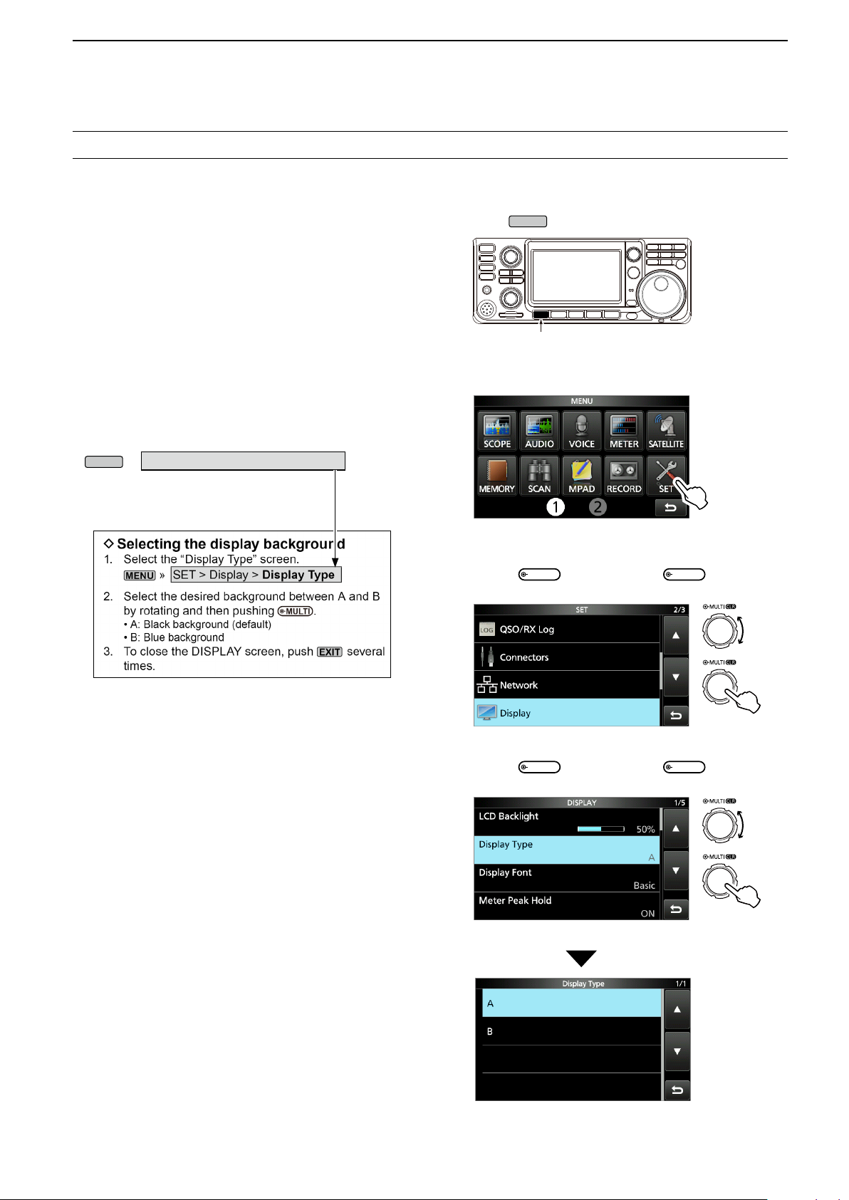
Routes to the Set modes and Setting screens
Routes to the Set mode, Setting screens and the setting
items are described in the following manner.
» SET > Display > Display Type
Instruction example
Detailed instruction
1. Push
• Opens the MENU screen.
.
Push
2. Touch [SET].
MENU screen
• Opens the SET screen.
3. Rotate
, and then push
“Display.”
to select
4. Rotate
“Display Type.”
SET screen
, and then push
DISPLAY screen
Push
to select
Push
“Display Type” screen
iv
Page 6

TABLE OF CONTENTS
IMPORTANT ............................................................... i
FEATURES ................................................................. i
EXPLICIT DEFINITIONS ............................................ i
SUPPLIED ACCESSORIES ....................................... i
FCC INFORMATION ..................................................ii
ABOUT CE AND DOC ................................................ ii
DISPOSAL ..................................................................ii
TRADEMARKS ...........................................................ii
ABOUT THE TOUCH SCREEN ................................iii
VOICE CORDING TECHNOLOGY ...........................iii
ABOUT THE MANUALS ............................................ iii
ABOUT THE INSTRUCTIONS ..................................iv
PRECAUTIONS ........................................................vii
1 PANEL DESCRIPTION ������������������������������������ 1-1
Front panel ....................................................... 1-1
Rear panel ........................................................ 1-3
Touch screen display ........................................ 1-4
D FUNCTION screen .................................... 1-6
D MENU screen ............................................ 1-6
D QUICK MENU ............................................ 1-6
D Multi-function menus .................................. 1-7
Multi-function dial ............................................. 1-7
Keyboard entering and editing ......................... 1-8
D Entering and editing characters ................. 1-8
D Keyboard types .......................................... 1-9
D Entering and editing ................................... 1-9
D Entering and editing example .................. 1-10
2 INSTALLATION AND CONNECTIONS ����������� 2-1
Selecting a location .......................................... 2-1
Using the desktop stands ................................. 2-1
Connecting an external DC power supply ........ 2-1
Heat dissipation ................................................ 2-1
Grounding ......................................................... 2-1
3 BASIC OPERATION ���������������������������������������� 3-1
When rst applying power ................................ 3-1
Turning power ON or OFF ................................ 3-1
Adjusting the volume level ................................ 3-1
Selecting the VFO and Memory modes ........... 3-1
Using the VFO mode ........................................ 3-1
D Selecting VFO A or VFO B ......................... 3-1
D Equalizing VFO A and VFO B .................... 3-1
Dualwatch operation ......................................... 3-2
Selecting the Main and Sub bands ................... 3-2
D Swapping the Main band and Sub band .... 3-2
Selecting the operating band ............................ 3-3
D Using the band stacking registers .............. 3-3
Selecting the operating mode ........................... 3-3
Setting the frequency ....................................... 3-4
D Using the Main Dial .................................... 3-4
D About the Tuning Step function .................. 3-4
D Changing the Tuning Step ......................... 3-4
D About the 1 MHz Step Tuning function ...... 3-4
D About the 1 Hz step Fine Tuning function .. 3-4
D About the 1/4 Tuning function .................... 3-5
D About the Auto Tuning Step function .........3-5
D Directly entering a frequency ..................... 3-5
D Band Edge Beep ........................................ 3-6
D Entering a Band Edge ................................ 3-7
RF gain and SQL level ...................................3-10
Dial Lock function ........................................... 3-10
Adjusting the transmit output power ............... 3-10
D Adjusting the transmit output power ........ 3-10
Transmit Power Limit function ........................3-10
Meter display .................................................. 3-11
D Meter display selection ............................ 3-11
D Multi-function meter ................................. 3-11
Adjusting the microphone gain ....................... 3-11
4 RECEIVING AND TRANSMITTING ����������������� 4-1
Preampliers .................................................... 4-1
Attenuator ......................................................... 4-1
RIT function ...................................................... 4-1
D RIT monitor function .................................. 4-1
D CW Auto Tuning function ........................... 4-1
AGC function control ........................................ 4-2
D Selecting the AGC time constant
preset value ............................................... 4-2
D Setting the AGC time constant ................... 4-2
Using the Digital Twin PBT ............................... 4-3
Selecting the IF lter ......................................... 4-4
Selecting the IF lter shape .............................. 4-4
Noise Blanker ................................................... 4-5
D Adjusting the NB level and time ................. 4-5
Noise Reduction ............................................... 4-6
D Adjusting the Noise Reduction level .......... 4-6
Notch Filter ....................................................... 4-6
D Selecting the Notch lter type .................... 4-6
D Setting the Manual Notch lter ................... 4-6
Monitor function ................................................ 4-7
IP Plus function ................................................4-7
Setting the Speech Compressor ...................... 4-8
D Setting before using the Speech
Compressor function .................................. 4-8
D Using the Speech Compressor function .... 4-8
Split frequency operation .................................. 4-9
D Using the Quick Split function .................... 4-9
D Using the receive and transmit frequencies
set to VFO A and VFO B ............................ 4-9
Split Lock function .......................................... 4-10
Setting the transmit lter width ....................... 4-10
v
Page 7

Operating CW ................................................. 4-10
D Setting the CW pitch control .................... 4-10
D Setting the key speed .............................. 4-10
D Using the Break-in function ...................... 4-11
D Monitoring the CW side tone ................... 4-11
D About the electronic Keyer function ......... 4-12
5 SCOPE OPERATION ��������������������������������������� 5-1
Spectrum scope screen .................................... 5-1
D Marker ........................................................ 5-1
D Using the Spectrum Scope ........................ 5-1
D Center mode .............................................. 5-2
D Fixed mode ................................................ 5-2
D Touch screen operation .............................5-2
D Mini scope screen ...................................... 5-2
Audio scope screen .......................................... 5-3
D AUDIO SCOPE SET screen ...................... 5-3
6 SD CARD ��������������������������������������������������������� 6-1
About the SD cards .......................................... 6-1
Saving data ...................................................... 6-1
Inserting ............................................................ 6-1
Formatting ........................................................ 6-1
Unmounting ...................................................... 6-2
Saving the setting data ..................................... 6-2
Loading the saved data .................................... 6-3
Deleting a data le ............................................ 6-4
Displaying the card information ........................ 6-4
Importing or Exporting a CSV format le .......... 6-5
D Importing .................................................... 6-5
D Exporting .................................................... 6-6
About the SD card folders ................................ 6-7
7 SATELLITE COMMUNICATION ���������������������� 7-1
Satellite communications outline ...................... 7-1
Selecting the satellite mode ............................. 7-1
D Setting the satellite VFO ............................ 7-1
D Selecting NOR/REV tracking ..................... 7-1
Loop test procedure ......................................... 7-2
Satellite operation ............................................. 7-3
Satellite memories ............................................ 7-3
D Satellite memory screen ............................ 7-3
8 SET MODE ������������������������������������������������������� 8-1
Set mode description ........................................ 8-1
Tone Control/TBW ............................................ 8-2
Function ............................................................ 8-2
My Station ........................................................ 8-5
DV/DD Set ........................................................ 8-6
QSO/RX Log .................................................... 8-8
Connectors ..................................................... 8-11
Network .......................................................... 8-14
Display ............................................................ 8-15
Time Set .........................................................8-18
SD Card .......................................................... 8-18
Others ............................................................. 8-19
9 CLOCK ������������������������������������������������������������� 9-1
Setting the date and time ................................. 9-1
D Setting the date .......................................... 9-1
D Setting the current time .............................. 9-1
D Setting the UTC offset ............................... 9-1
NTP function .....................................................9-1
D Using the NTP Time Synchronize function 9-1
D Using the NTP function .............................. 9-1
10 MAINTENANCE ��������������������������������������������� 10-1
Cleaning ......................................................... 10-1
Replacing fuse ................................................ 10-1
Resetting ........................................................ 10-2
D Partial reset .............................................. 10-2
D All reset .................................................... 10-2
Cloning ........................................................... 10-3
Touch screen calibration function ................... 10-5
Troubleshooting .............................................. 10-6
D D-STAR operation ....................................10-8
11 SPECIFICATIONS ����������������������������������������� 11-1
D General .................................................... 11-1
D Transmitter ............................................... 11-2
D Receiver ................................................... 11-3
12 OPTIONS ������������������������������������������������������� 12-1
Options ........................................................... 12-1
Mounting the MB-118 ..................................... 12-2
Attaching the MB-123 ..................................... 12-2
13 CONNECTOR INFORMATION ����������������������13-1
[ACC] .............................................................. 13-1
[DC 13.8 V] ..................................................... 13-1
[PHONES] ...................................................... 13-1
[KEY] .............................................................. 13-2
[EXT-SP MAIN] / [EXT-SP SUB] .....................13-2
[USB] .............................................................. 13-2
[LAN] .............................................................. 13-2
[DATA] ............................................................13-2
[MIC] ............................................................... 13-3
[REMOTE] ...................................................... 13-3
[REF IN 10MHz] ............................................. 13-3
[144MHz ANT] ................................................ 13-3
[430MHz ANT] ................................................ 13-3
[1200MHz ANT] .............................................. 13-3
ABOUT THE LICENSES �������������������������������������������� I
INDEX������������������������������������������������������������������������ II
vi
Page 8

PRECAUTIONS
R DANGER HIGH RF VOLTAGE! NEVER touch an
antenna or antenna connector while transmitting. This could
cause an electrical shock or burn.
R DANGER! NEVER operate the transceiver near
unshielded electrical blasting caps or in an explosive
atmosphere. This could cause an explosion and death.
R WARNING RF EXPOSURE! This device emits Radio
Frequency (RF) energy. Extreme caution should be
observed when operating this device. If you have any
questions regarding RF exposure and safety standards
please refer to the Federal Communications Commission
Ofce of Engineering and Technology’s report on
Evaluating Compliance with FCC Guidelines for Human
Radio Frequency Electromagnetic Fields (OET Bulletin 65).
R WARNING! NEVER operate the transceiver with a
headset or other audio accessories at high volume levels. If
you experience a ringing in your ears, reduce the volume or
discontinue use.
R WARNING! NEVER apply AC power to the [DC13.8V]
socket on the transceiver rear panel. This could cause a re
or damage the transceiver.
R WARNING! NEVER apply more than 16 V DC to the
[DC13.8V] socket on the transceiver rear panel. This could
cause a re or damage the transceiver.
R WARNING! NEVER reverse the DC power cable
polarity. This could cause a re or damage the transceiver.
R WARNING! NEVER remove the fuse holder on the DC
power cable. Excessive current caused by a short could
cause a re or damage the transceiver.
R WARNING! NEVER let metal, wire or other objects
contact the inside of the transceiver, or make incorrect
contact with connectors on the rear panel. This could cause
an electric shock or damage the transceiver.
R WARNING! NEVER operate or touch the transceiver
with wet hands. This could cause an electric shock or
damage to the transceiver.
R WARNING! NEVER operate the equipment if you notice
an abnormal odor, sound or smoke. Immediately turn OFF
the power and/or remove the DC power cable. Contact your
Icom dealer or distributor for advice.
R WARNING! NEVER put the transceiver on an unstable
place where the transceiver may suddenly move or fall.
This could cause an injury or damage the transceiver.
CAUTION: DO NOT expose the transceiver to rain, snow
or any liquids. They could damage the transceiver.
CAUTION: DO NOT change the internal settings of the
transceiver. This could reduce transceiver performance
and/or damage to the transceiver. The transceiver warranty
does not cover any problems caused by unauthorized
internal adjustments.
CAUTION: DO NOT install or place the transceiver in a
place without adequate ventilation, or block any cooling
vents on the top, rear, sides or bottom of the transceiver.
Heat dissipation may be reduced and damage the
transceiver.
CAUTION: NEVER use harsh solvents such as Benzine or
alcohol when cleaning. This could damage the transceiver
surfaces. If the surface becomes dusty or dirty, wipe it clean
with a soft, dry cloth.
CAUTION: NEVER leave the transceiver in areas with
temperatures below –10°C (+14°F) or above +60°C
(+140°F) for mobile operations.
CAUTION: DO NOT place the transceiver in excessively
dusty environments. This could damage the transceiver.
CAUTION: DO NOT place the transceiver against walls
or putting anything on top of the transceiver. This may
overheat the transceiver.
CAUTION: DO NOT set the transceiver’s RF output power
to more than a connected linear amplier’s maximum input
level. Otherwise, the linear amplier will be damaged.
CAUTION: DO NOT use non-Icom microphones. Other
microphones have different pin assignments, and may
damage the transceiver.
BE CAREFUL! The transceiver will become hot when
operating the transceiver continuously for long periods of
time.
NEVER leave the transceiver in an insecure place to avoid
use by unauthorized persons.
Turn OFF the transceiver’s power and/or disconnect the DC
power cable when you will not use the transceiver for long
period of time.
The LCD display may have cosmetic imperfections
that appear as small dark or light spots. This is not a
malfunction or defect, but a normal characteristic of LCD
displays.
R WARNING! NEVER operate the transceiver during a
lightning storm. It may result in an electric shock, cause
a re or damage the transceiver. Always disconnect the
power source and antenna before a storm.
vii
Page 9
Front panel
POWER
TRANSMIT
CALL
DR
VOX/BK-IN
AF RF/SQL
M/S
OFF
M/S
OFF
MENU
FUNCTION
M.SCOPE
QUICK
AF RF/SQL
NOTCH
P.AMP
ATT
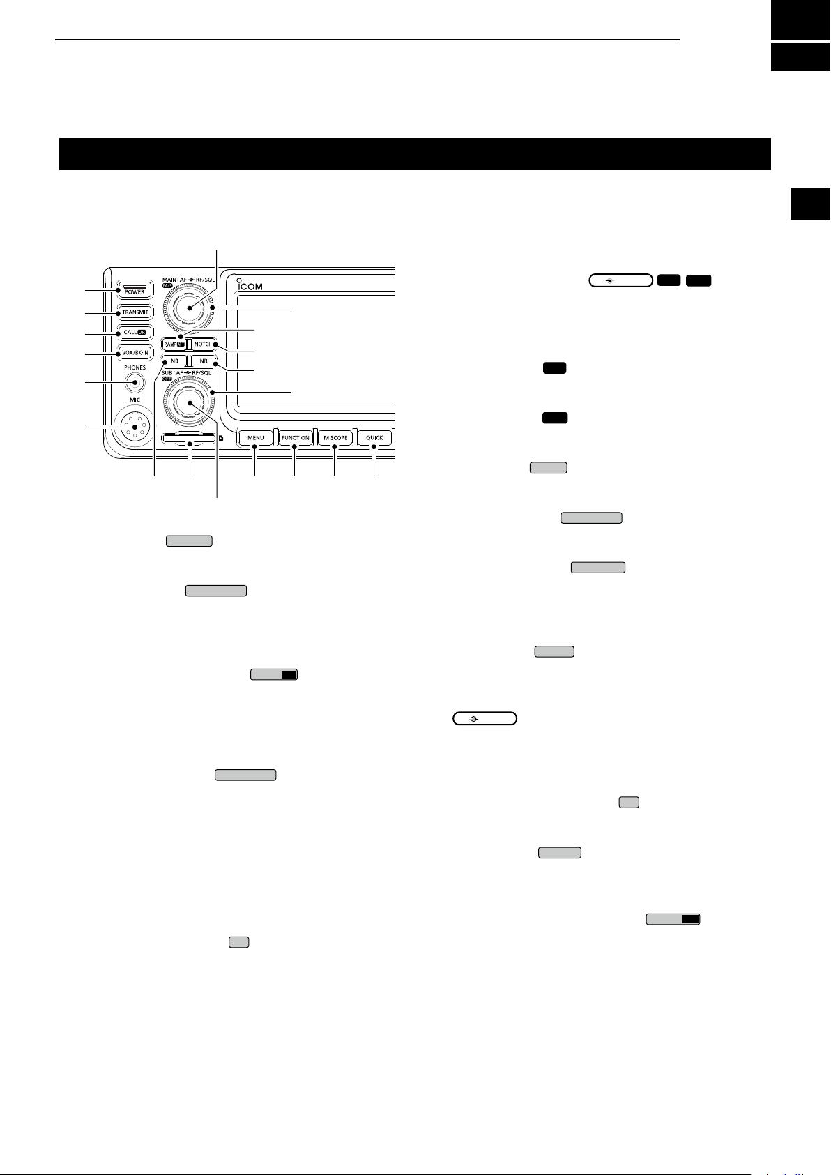
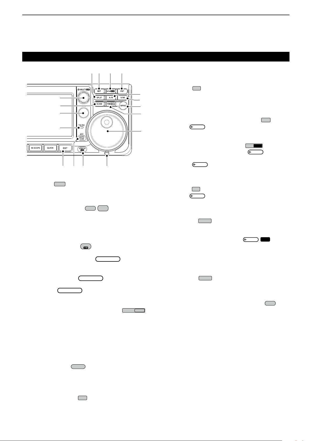
PANEL DESCRIPTION
1
This section describes the keys, controls and dials that you use to operate the IC-9700.
Refer to the pages posted beside each key, control, or dial for details.
o
q
w
e
r
t
y
u
i
q POWER KEY
Turns the transceiver ON or OFF.
w TRANSMIT KEY
z Toggles between transmit and receive.
z In the DD mode, turns the TX Inhibit function
ON or OFF.
e CALL/DR FUNCTION KEY
z Push to toggle between the Call channel mode
and the VFO/Memory modes.
z Hold down for 1 second to turn the DR function
ON or OFF.
r VOX/BREAK-IN KEY
Turns the VOX function (p. 4-7) and Break-in
function (p. 4-12) ON or OFF.
t HEADPHONE JACK [PHONES] (p� 2-1)
Connects to standard stereo headphones.
y MICROPHONE CONNECTOR [MIC] (p� 2-1)
Connects to the supplied or an optional microphone.
u NOISE BLANKER KEY NB (p� 4-5)
Turns the Noise Blanker ON or OFF.
!0
o
(p� 3-1)
(p� 3-9)
!4
!7
!6
!5
!4
!1 !2 !3
(p� 7-1)
o VOLUME CONTROL
L The upper control is for the Main band, and the
lower control is for the Sub band.
z Adjust the audio output level.
z Push to select the Main or Sub band.
z Hold down
between the Main and Sub band’s frequency
and operating modes.
z Hold down
Dualwatch function ON or OFF.
!0 MENU KEY
Opens the MENU screen.
!1 FUNCTION KEY
Opens the FUNCTION screen.
!2 MINI SCOPE KEY
Displays the Mini scope or Spectrum scope.
L The Mini scope is displayed only when the
Dualwatch function is OFF.
!3 QUICK KEY
Opens the QUICK MENU screen.
!4 RF GAIN CONTROL/SQUELCH CONTROL
(p� 3-9)
L The upper control is for the Main band, and the
lower control is for the Sub band.
Adjusts the RF gain and squelch threshold levels.
!5 NOISE REDUCTION KEY NR (p� 4-6)
Turns the Noise Reduction function ON or OFF.
!6 NOTCH KEY
Turns ON or OFF, and selects the Notch function
type.
!7 PREAMP/ATTENUATOR KEY
Turns ON or OFF, and selects one of two receive
RF preampliers or turns the Attenuator ON or OFF.
(upper) for 1 second to toggle
(lower) for 1 second to turn the
(p� 1-6)
(p� 1-6)
(p� 4-6)
/
(p� 1-6)
(p� 5-1)
/
(p� 4-1)
(p� 3-1)
1
2
3
4
5
6
7
8
9
10
11
12
13
14
15
16
17
18
19
20
21
i SD CARD SLOT [SD CARD] (p� 6-1)
Accepts an SD card.
1-1
Page 10
1
EXIT
AFC
AUTO
TUNE
SPEECH
MAIN DIAL
MAIN DIAL
MAIN DIAL
TONE
MPAD
V/M
A/B
PBT
MULTI
kHz
M-CH
MULTI
MULTI
RIT
MULTI
SPLIT
MULTI
CLR
SCAN
XFC
PANEL DESCRIPTION
Front panel (Continued)
#0 @7@9 @8
@6
!8 EXIT KEY
#1
#2
#3
#4
!8 @0
(p� 1-6)
!9
@1
@5
@4
@3
@2
Exits a setting screen or returns to the previous
screen.
!9 AFC/AUTO TUNE KEY
/
(p� 4-1)
z In the FM or DV mode, turns the Auto
Frequency Control function ON or OFF.
z In the CW mode, automatically tunes the
operating frequency to a close-by CW signal.
@0 SPEECH/LOCK KEY
(p� 3-9)
Announces the operating frequency or receiving
mode, or electronically locks
.
@1 FRICTION ADJUSTER
Adjusts the friction of
@2 MAIN DIAL
(p� 3-3)
.
Changes the operating frequency.
@3 TONE/RX CALL SIGN CAPTURE KEY
RX→CS
z In the FM mode, displays the Tone Set window.
For European versions: While holding down
[PTT], hold down this key to send the 1750 Hz tone.
z In the DV mode, push to display the RX History
list, or hold down for 1 second to capture the
latest received call sign (station or repeater) as
a temporary call destination.
@4 MEMO PAD KEY
Sequentially calls up the contents in the Memo
Pads, or saves the displayed contents into the
Memo Pad.
@5 VFO/MEMORY KEY
(p� 3-1)
Switches between the VFO and Memory mode, or
copies the memory channel contents to the VFO.
@6 A/B KEY
(p� 3-1)
Switches between VFO A and VFO B, or copies the
selected VFO’s frequency, mode and lter settings
to the other VFO.
@7 PASSBAND TUNING CONTROL KEY
Enables
to adjust the Passband Tuning
(p� 4-3)
Control (PBT).
@8 kHz TUNING STEP/M-CH KEY
In the VFO mode, push to enable
(p� 4-1)
to adjust
the kHz Tuning Control, or hold down for 1 second
to enable
to select the Memory Channel.
L In the Memory or Call channel mode, it only
enables the Memory channel selection.
@9 RIT KEY
Enables
(p� 4-1)
to adjust the Receiver Incremental
Tuning (RIT), and it turns the Receiver Incremental
Tuning (RIT) function ON or OFF.
#0 SPLIT KEY
(p� 4-10)
Turns the Split function ON or OFF.
#1 MULTI-FUNCTION CONTROL
/
(p� 1-6)
z Displays the Multi-function menu for various
adjustments, or selects a desired item.
z Hold down for 1 second to clear the RIT shift
frequency or the PBT setting.
#2 SCAN KEY
Displays the Scan Select window, or starts the
previously selected scan.
#3 TRANSMIT FREQUENCY CHECK KEY
(p� 4-9)
z In the Split or Duplex mode, enables you to
monitor the transmit frequency while holding the
key down.
z In Simplex mode, temporally opens the squelch
and cancels the noise reduction function while
holding the key down.
L In the DV mode, enables you to monitor signals in
the FM or DV mode, depending on the Digital Monitor
setting.
#4 TX/RX INDICATOR (p� 3-9)
Lights red while transmitting and lights green while
receiving.
1-2
Page 11
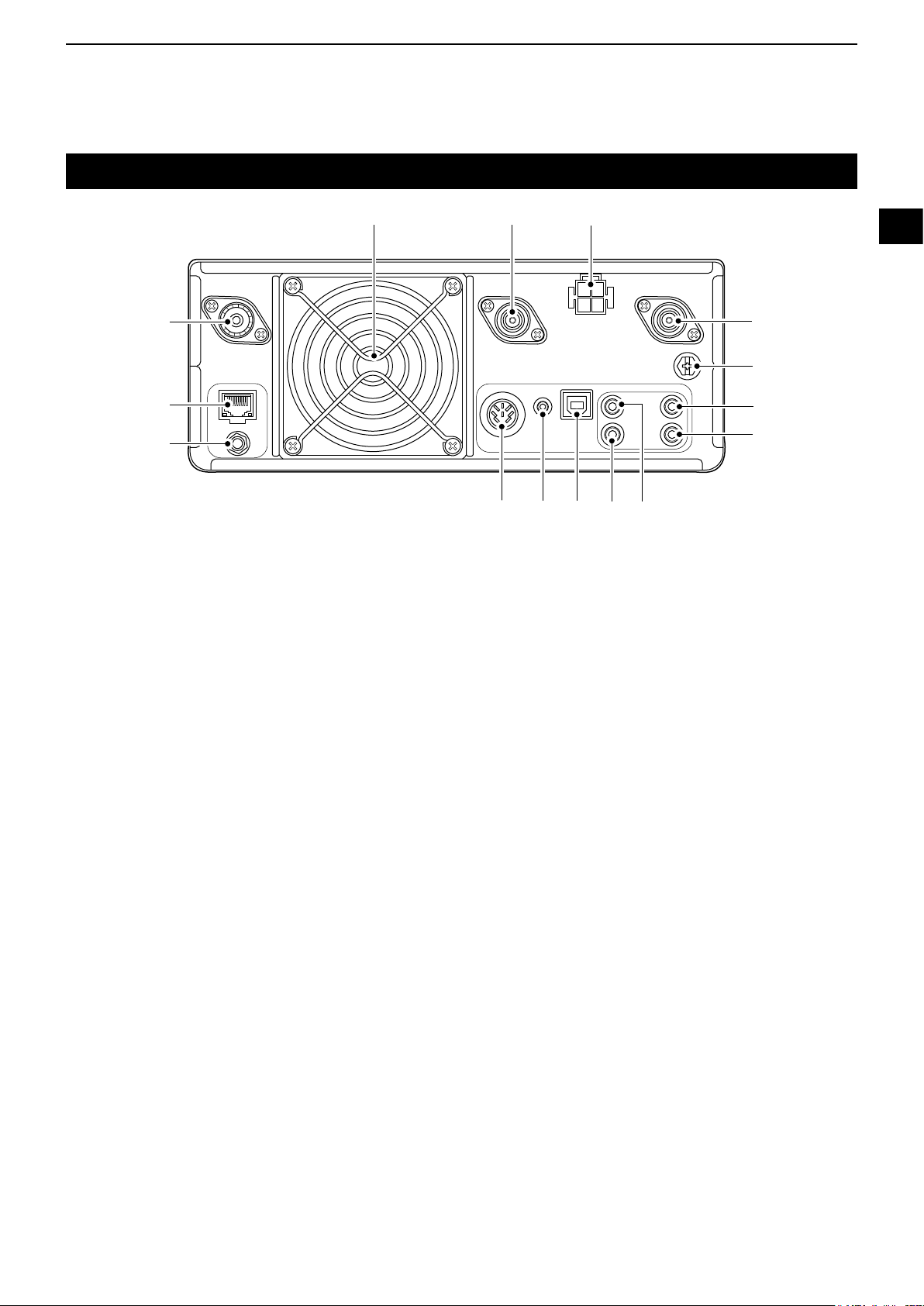
Rear panel
PANEL DESCRIPTION
1
q
w
e
q ANTENNA CONNECTOR [144 MHz ANT] (p. 13-3)
Connects to a 50 Ω PL-259 coax connector.
w ETHERNET CONNECTOR [LAN] (p. 13-2)
Connects to a PC network through a LAN.
e
REFERENCE SIGNAL INPUT [REF IN 10 MHz] (p. 13-3)
Inputs a 10 MHz reference signal through the SMA
connector.
r SOCKET [ACC] (p. 13-1)
Connects to devices to control an external unit or to
control the transceiver.
t DATA JACK [DATA] (p. 13-2)
Connects to devices to control an external unit or to
control the transceiver with 2.5 mm (1⁄10") stereo
plug.
!4!5
r t y u i
!1 GROUND TERMINAL [GND] (p. 2-1)
Connects to ground to prevent electrical shocks,
TVI, BCI and other problems.
!2
ANTENNA CONNECTOR [1200 MHz ANT] (p. 13-3)
Connects to a 50 Ω Type N coax connector for the
1.2 GHz band.
!3
DC POWER SOCKET [DC 13.8 V] (pp. 2-1 and 13-1)
Accepts 13.8 V DC through the DC power cable.
!4 ANTENNA CONNECTOR [430 MHz ANT] (p. 13-3)
Connects to a 50 Ω Type N coax connector for the
440 MHz band.
!5 COOLING FAN
Cools the PA unit when necessary.
!3
!2
!1
!0
o
1
2
3
4
5
6
7
8
9
10
11
12
13
14
15
16
17
y USB PORT (B TYPE) [USB] (p. 13-2)
Connects to a PC.
u KEY JACK [KEY] (p. 13-2)
Connects to a straight key, paddle, or an external
electronic keyer with 3.5 mm (1⁄8") stereo plug.
i CI-V REMOTE CONTROL JACK [REMOTE]
(p. 13-3)
Connects to a PC or other transceiver for external
control.
o EXTERNAL SPEAKER JACK [EXT-SP SUB]
!0 EXTERNAL SPEAKER JACK [EXT-SP MAIN]
(p. 13-2)
Accepts a 4~8 Ω external speaker with 3.5 mm
(1⁄8") mono plugs.
18
19
20
21
1-3
Page 12
1
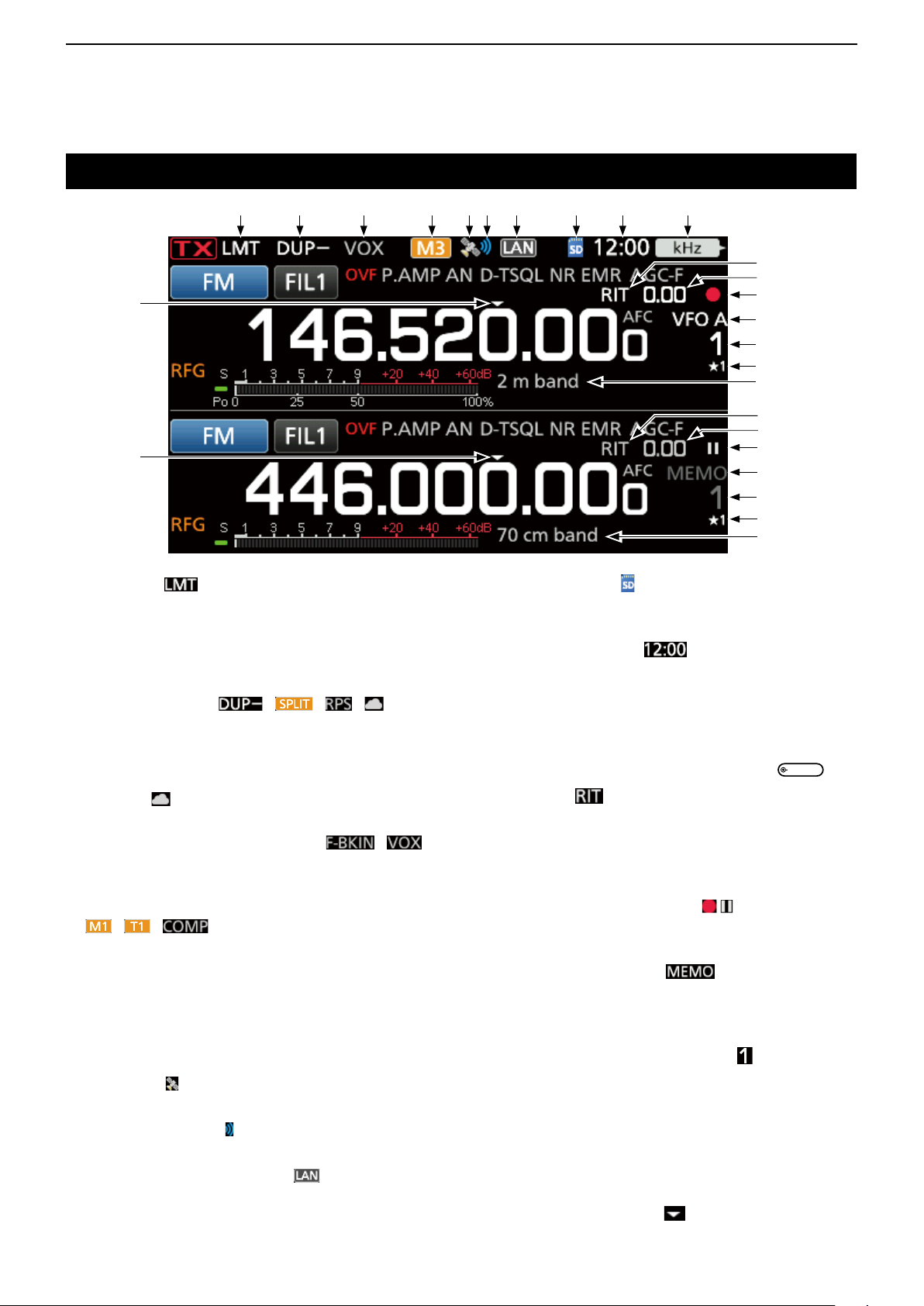
PANEL DESCRIPTION
Touch screen display
q w r iu o !0
!8
!8
q LMT ICON
Displayed if the power ampli er temperature
becomes extremely high, and the Protection
function is activated after transmitting continuously
for a long period of time.
w DUPLEX/SPLIT/REPEATER MODE/INTERNAL
GATEWAY ICONS / / /
Displays “DUP” when the Duplex mode is ON.
Displays “SPLIT” when the Split function is ON.
Displays “RPS” while using the Repeater Simplex
mode (RPS) in the DD mode.
Displays “ ” while using the Internal Gateway
function.
e t
y
!1
!2
!3
!4
!5
!6
!7
!1
!2
!3
!4
!5
!6
!7
i SD CARD ICON
Displayed when an SD card is inserted, and blinks
while accessing the SD card.
o CLOCK READOUT
Displays the current local time.
Touch the readout to display both the current local
time and UTC time.
!0 FUNCTION INDICATOR FOR MULTI-FUNCTION
CONTROL
Displays the function that is assigned to
!1 RIT ICON
Displayed when the RIT function is ON.
(p� 6-1)
(p� 4-1)
(p� 8-7)
MULTI
.
e BK-IN/F-BKIN/VOX INDICATORS
Displayed while the Semi Break-in, Full Break-in or
VOX function is ON.
r M1~M8/T1~T8/SPEECH COMPRESSOR ICONS
/ /
Displays “M1”~“M8” while “External Keypad” on the
CONNECTORS screen is set to ON and you are
using the Memory Keyer function (p. 4-14).
Displays “T1”~“T8” while using the Voice TX
memory.
Displays “COMP” when the Speech Compressor
function is ON.
t GPS ICON
Displays the status of the connected GPS receiver.
y GPS ALARM ICON
Displayed when the GPS Alarm function is ON.
u NETWORK CONTROL ICON
Displayed while the transceiver and the optional
RS-BA1 are connected through a LAN cable for
Remote control operation.
/
!2 RIT/DUPLEX OFFSET FREQUENCY READOUT
Displays the shift offset frequency for the RIT or
Duplex functions, while these functions are ON.
!3 VOICE RECORDER ICONS
Displayed while recording or pausing the Voice
recorder.
!4 VFO/MEMORY ICONS
Displays “VFO A” or “VFO B” when the VFO
mode is selected, and displays “MEMO” when the
Memory mode is selected.
!5 MEMORY CHANNEL READOUT
Displays the selected memory channel number.
!6 SELECT MEMORY CHANNEL ICON
Indicates that the displayed memory channel is
assigned as a Select Memory channel (★1~★3).
!7 MEMORY NAME (p� 4-8)
Displayed when the Memory name is entered.
!8 QUICK TUNING ICON
Displayed when the Quick Tuning Step function is
1-4
ON.
/
(p� 3-1)
Page 13
AF RF/SQL
TX
!9
@0 @1 @2 @3 @4 @5
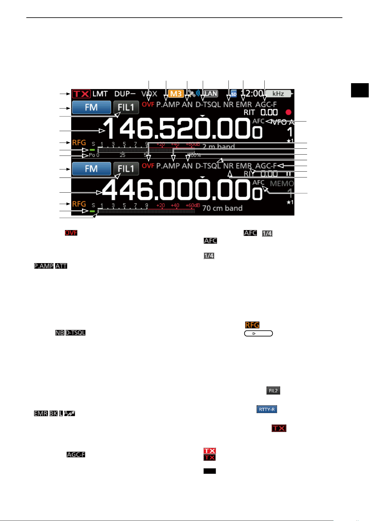
PANEL DESCRIPTION
1
#3
#2
#1
#0
@9
@8
@7
#2
#1
#0
@9
@8
@7
!9 OVF ICON
Displayed when an excessively strong signal is
received.
@0 PREAMPLIFIER/ATTENUATOR ICONS
/
Displayed when one the Preampli ers is ON, or the
Attenuator is ON.
@1 NOTCH INDICATOR
Displays “AN” when the Auto Notch function is ON,
and “MN” is displayed when the Manual Notch
function is ON.
@6
!9
@0
@1
@2
@3
@4
@5
@6
@6 AFC/
“
“ ” is displayed while the 1/4 Tuning function is
@7 MULTI-FUNCTION METER (p� 3-11)
Displays various values and levels, depending on
@8 RX STATUS INDICATOR
Lights green when a signal is received, or the
1
/4 ICON / (p� 8-5)
is displayed while the Auto Frequency
”
Control (AFC) is ON.
ON. (p. 3-5)
the function that you selected.
squelch is open.
1
2
3
4
5
6
7
8
9
10
11
12
13
14
15
@2 NOISE BLANKER/TONE/DIGITAL SQUELCH
ICONS
Displayed when the Noise Blanker function is ON,
when various tone functions are ON, or when
various digital squelch functions are ON.
@3 NOISE REDUCTION/AUTO TUNE INDICATORS
Displays “NR” when the Noise Reduction function is
ON.
Displays “AUTOTUNE” when the Auto Tuning
function is ON.
@4 EMR/BK/PACKET LOSS/AUTO REPLAY ICONS
Displayed when the EMR (Enhanced Monitor
Request) function is ON, when the BK (Break-in)
function is ON, when Packet loss has occured, or
when the Automatic Reply function is ON.
@5 AGC ICON
Displayed while the Auto Gain Control (AGC) is ON.
/
/ / /
(p� 3-9)
@9 RF GAIN ICON
Displayed when
counterclockwise from the 11 o’clock position. The
icon indicates that the RF gain is reduced.
#0 MAIN BAND FREQUENCY READOUT
SUB BAND FREQUENCY READOUT (p� 3-4)
Displays the transmit or receive frequency for the
Main and Sub bands.
#1 IF FILTER INDICATOR
Displays the selected IF lter number.
#2 MODE INDICATOR
Displays the selected operating mode.
#3 TX STATUS INDICATOR
Displays the transmit status of the displayed
frequency.
• is displayed while transmitting.
•
is displayed when the selected frequency is
outside of the band edge frequency range.
•
is displayed when transmission is inhibited (p. 3-10)
1-5
(p� 3-10)
(outer) is set to the
(p� 4-4)
(p� 3-3)
16
17
18
19
20
21
Page 14
1
FUNCTION
EXIT
QUICK
MENU
EXIT
PANEL DESCRIPTION
Touch panel (Continued)
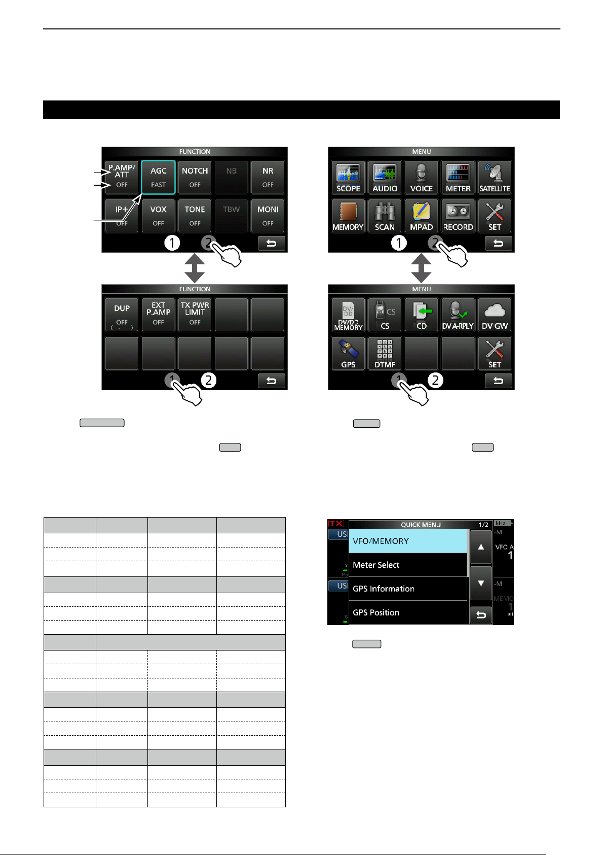
D FUNCTION screen
Function
name
Selected
value
Lights
blue when
active
z Push
the selected mode.
LTo close the FUNCTION screen, push
L Touching q or w at the bottom of the screen selects
Function screen 1 or 2.
FUNCTION screen list
*1 Touch for 1 second to select the function.
*2 Touch for 1 second to open its function menu.
P�AMP/ATT AGC
OFF FAST OFF OFF
P.AMP MID AN ON
*
1
ATT
2
*
NR
OFF OFF OFF OFF
ON ON ON BKIN
2
*
COMP
OFF OFF DTCS
ON TONE DTCS (T)
2
*
D�SQL
OFF WIDE OFF OFF
DSQL MID ON ON
CSQL NAR
2
*
DUP
OFF OFF OFF OFF
DUP– ON ON ON
DUP+
to open the FUNCTION screen in
.
2
*
SLOW MN
IP+ VOX
TSQL
TBW 1/4 MONI
EXP P�AMP RPS TX PWR LIMIT
NOTCH
TONE (T)/DTCS (R)
2
*
TONE
2
*
2
*
NB
BKIN
F-BKIN
DTCS (T)/TSQL (R)
TONE (T)/TSQL (R)
D MENU screen
z Push
selected band.
LTo close the MENU screen, push
L Touching q or w on the bottom of the screen selects
MENU screen 1 or 2.
to open the MENU screen on the
.
D QUICK MENU
2
*
2
*
z Push
2
*
2
*
to open the QUICK MENU screen.
1-6
Page 15
D Multi-function menus
MULTI
VOX/BK-IN
NB
NOTCH
MULTI
Rotate
MULTI
MULTI
MULTI
MULTI
MULTI
Touch the edge to
turn ON or OFF
Push
PANEL DESCRIPTION
1
Multi-function dial
When the Multi-function menu is closed,
be enabled to adjust functions that are either on the
upper right three keys or in the Multi-function menus.
The function is displayed in the upper right edge of the
screen.
Function indicator for
can
1
2
3
4
Multi-function menu
z Open the Multi-function menu by pushing
(Multi-function control).
z Open special menus by holding down
, NR, or
for 1 second.
z While the Multi-function menu is open, touch the
desired item and rotate
to set the desired
value.
Multi-function menu items
*1
Touch the edge to turn the function ON or OFF, or
when you want to adjust.
*2 Touch the item for 1 second to enable
SSB SSB-D CW RTTY
2
*
1, *2
*
*
*
*
1, *2
*
1, *2
*
1
*
2
*
2
2
RF POWER
MIC GAIN
MONITOR
2
RF POWER
TX INHIBIT
GAIN
ANTI VOX
DELAY
VOICE DELAY
RF POWER
MIC GAIN
COMP
MONITOR
FM/AM/DV DD NB NR
RF POWER
MIC GAIN
MONITOR
NOTCH VOX BK-IN TX PWR LIMIT
POSITION
WIDTH
*
1, *2
*
2
*
*
2
*
2
*
RF POWER
2
KEY SPEED
CW PITCH
2
*
1
*
2
1
*
LEVEL
DEPTH
WIDTH
DELAY
*
*
2
*
2
*
2
*
2
*
2
RF POWER
2
*
2
MONITOR
RF POWER
TPF
LEVEL
LIMIT
5
,
*1 You can independently enable
function for the MAIN and SUB bands
to adjust
.
the
*2 On the Multi-function menus, touch the item for
1 second to assign the function to
.
Indicator Action
Rotate Adjusts the RIT frequency.
1
*
RIT
kHz
.
M-CH
2
*
1
*
1, *2
*
2
*
2
*
PBT1
PBT2
RF PWR
MIC G
COMP
MONI
SPEED
PITCH
NB LEV
NB DEP
NB WID
NR LEV
NOTCH
VOX G
A-VOX
VOX D
BKIN D
Hold down Clears the RIT frequency.
Changes the operating frequency on the kHz
1
*
steps.
Selects Memory channels.
1
*
Using the DR function, selects an individual
station or preset repeater.
Rotate Adjusts the Shift value for PBT1.
1
*
Hold down Clears the Twin PBT setting.
Rotate Adjusts the Shift value for PBT2.
1
*
Hold down Clears the Twin PBT setting.
2
*
Adjusts the transmit output power.
2
*
Adjusts the microphone gain.
2
*
Adjusts the Speech Compressor level.
2
*
Adjusts the audio level for the Monitor function.
2
*
Sets the Key speed.
2
*
Sets the CW pitch.
2
*
Adjusts the Noise Blanker level.
2
*
Adjusts the DEPTH (Noise attenuation level).
2
*
Adjusts the WIDTH (Blanking duration time).
2
*
Adjusts the transmit output power.
2
*
Adjusts the Notch frequency.
2
*
Adjusts the VOX gain.
2
*
Adjusts the ANTI VOX level.
2
*
Adjusts the VOX delay time.
2
*
Adjusts the Break-in delay time.
6
7
8
9
10
11
12
13
14
15
16
17
18
19
20
21
1-7
Page 16

1
PANEL DESCRIPTION
Keyboard entering and editing
D Entering and editing characters
You can enter and edit the items in the following table.
Menu Category Item Selectable characters
SET My Station My Call Sign (DV)/(DD) A to Z, 0 to 9, (space), / 8+4
TX Message (DV) A to Z, a to z, 0 to 9, (space), ˽ ! " # $ % & ' ( ) * +
, - . / : ; < = > ? @ [ \ ] ^ _ ` { � } ~
Network Network Name A to Z, a to z, 0 to 9, ! " # $ % & ( ) + , - . ; = @ [ ] ^
_ ` { } ~
Network User 1/2 ID A to Z, a to z, 0 to 9, ˽ ! " # $ % & ' ( ) * + , - . / : ; < =
Network User 1/2 Password
Network Radio Name A to Z, a to z, 0 to 9, (space), ˽ ! " # $ % & ' ( ) * +
Time Set NTP Server Address A to Z, a to z, 0 to 9, - . 64
SD Card Save Setting A to Z, a to z, 0 to 9, (space), ˽ ! " # $ % & ' ( ) * +
Export
MEMORY Memory Name A to Z, a to z, 0 to 9, (space), ˽ ! " # $ % & ' ( ) * +
KEYER Keyer Memory A to Z, 0 to 9, (space), / ? ^ . , @
DECODE RTTY Memory
VOICE VOICE TX RECORD A to Z, a to z, 0 to 9, (space), ˽ ! " # $ % & ' ( ) * +
CS UR, R1, R2 A to Z, 0 to 9, (space), / 8
DV/DD
MEMORY
DV GW Internal Gateway
GPS GPS TX Mode Unproto Address A to Z, a to z, 0 to 9, ˽ ! " # $ % & ' ( ) * + , - . / : ; <
DTMF DTMF MEMORY 0 to 9, A B C D * # 24
DR TO SELECT Direct input (UR)/(RPT) A to Z, 0 to 9, (space), / 8
Your Call Sign NAME A to Z, a to z, 0 to 9, (space), ˽ ! " # $ % & ' ( ) * +
CALL SIGN A to Z, 0 to 9, (space), / 8
Repeater List GROUP NAME, NAME A to Z, a to z, 0 to 9, (space), ˽ ! " # $ % & ' ( ) * +
SUB NAME A to Z, a to z, 0 to 9, (space), ˽ ! " # $ % & ' ( ) * +
CALL SIGN, GW CALL SIGN A to Z, 0 to 9, (space), / 8
Gateway Repeater
Settings
GPS Memory GROUP NAME, NAME A to Z, a to z, 0 to 9, (space), ˽ ! " # $ % & ' ( ) * +
SEND Direct Input 0 to 9, A B C D * # 24
(Server IP/Domain)
Terminal/AP, Call Sign,
Allowed Call Sign List
Object Name, Item Name A to Z, a to z, 0 to 9, ˽ ! " # $ % & ' ( ) * + , - . / : ; < =
Comment A to Z, a to z, 0 to 9, ˽ ! " # $ % & ' ( ) * + , - . / : ; < =
GPS Message A to Z, a to z, 0 to 9, (space), ˽ ! " # $ % & ' ( ) * +
> ? @ [ \ ] ^ _ ` { � } ~
• Password: Minimum 8 characters
, - . / : ; < = > ? @ [ \ ] ^ _ ` { � } ~
, - . / : ; < = > ? @ [ ] ^ _ ` { } ~
• Illegal characters: / : ; * < > \ |
, - . / : ; < = > ? @ [ \ ] ^ _ ` { � } ~
• “ *” (asterisk) has its unique use.
A to Z, 0 to 9, (space), ! $ & ? " ' - / . , : ; ( ) ↵
, - . / : ; < = > ? @ [ \ ] ^ _ ` { � } ~
, - . / : ; < = > ? @ [ \ ] ^ _ ` { � } ~
, - . / : ; < = > ? @ [ \ ] ^ _ ` { � } ~
, - . / : ; < = > ? @ [ \ ] ^ _ ` { � } ~
A to Z, a to z, 0 to 9, - .
A to Z, 0 to 9, (space)
= > ? @ [ \ ] ^ _ ` { � } ~
• Normally 12 characters
> ? @ [ \ ] ^ _ ` { � } ~
> ? @ [ \ ] ^ _ ` { � } ~
• Maximum characters you can enter differs, depending
on the data extension and altitude settings.
, - . / : ; < = > ? @ [ \ ] ^ _ ` { � } ~
, - . / : ; < = > ? @ [ \ ] ^ _ ` { � } ~
Maximum
characters
20
15
16
16
16
20
16
70
70
16
16
16
8
64
8
56
9
43
20
16
1-8
Page 17
PANEL DESCRIPTION
MENU
QUICK
MENU
1
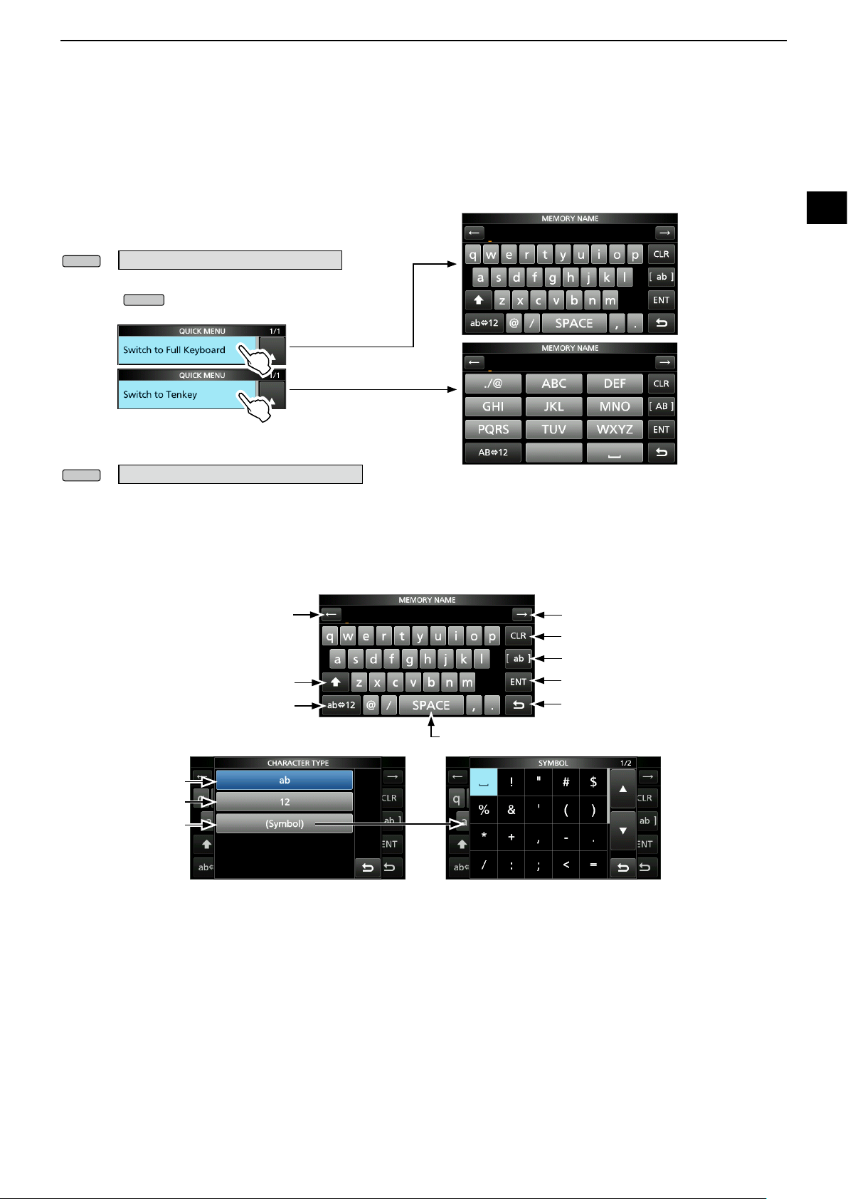
D Keyboard types
You can select the Full Keyboard or Tenkey pad in
“Keyboard Type” on the FUNCTION screen. (p. 8-4)
» SET > Function > Keyboard Type
L You can also temporarily switch in the QUICK MENU by
pushing
L You can select the full keyboard layout in “Full Keyboard
Layout” on the FUNCTION screen. (p. 8-4)
»
SET > Function > Full Keyboard Layout
D Entering and editing
.
Moves the cursor backward
Enters an uppercase letter
Selects alphabet mode
or number mode
Enters a space
Moves the cursor forward
Clears the entered character
Selects the character type
Saves the entry
Cancels entry and returns to the
previous screen
1
2
3
4
5
6
7
8
9
10
11
12
13
14
15
16
Alphabet mode
Number mode
Symbol mode
17
18
19
20
21
1-9
Page 18
1
MENU
Rotate
PANEL DESCRIPTION
Keypad entering and editing (Continued)
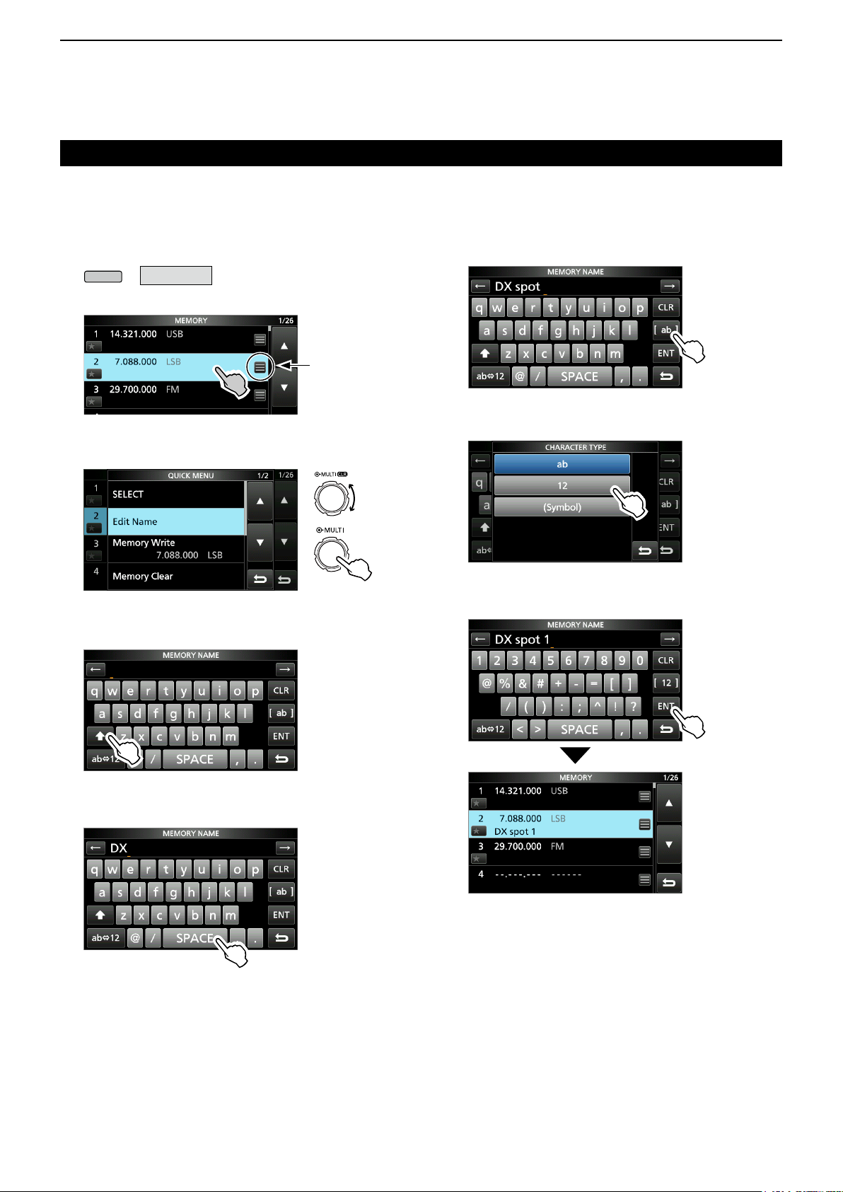
D Entering and editing example
Entering “DX spot 1” in the Memory channel 2
1. Open the MEMORY screen.
» MEMORY
2. Touch memory channel 2 for 1 second.
• Opens the QUICK MENU.
3. Select “Edit Name.”
• Opens the MEMORY NAME screen.
4. Touch [ ], and then touch [D].
You can also
open the
QUICK MENU
by touching this
key.
Push
9. Touch [ab].
• Opens the entry CHARACTER TYPE screen.
10. Touch [12].
11. To uch [1] .
12. Touch [ENT] to save the entry.
5. Touch [ ] again, and then touch [X].
6. Touch [SPACE].
• Returns to the previous screen.
• Enters a space.
7. Touch [s], [p], [o], and then [t].
8. Touch [SPACE].
• Enters a space.
1-10
Page 19
INSTALLATION AND CONNECTIONS
2
Selecting a location
Select a location for the transceiver that allows
adequate air circulation, free from extreme heat, cold
or vibration, and other electromagnetic sources.
Never place the transceiver in areas such as:
• Temperatures below –10°C (+14°F) or above +60°C
(+140°F).
• An unstable place that slopes or vibrates.
• In direct sunlight.
• High humidity and temperature environments.
• Dusty environments.
• Noisy environments.
Using the desktop stands
The transceiver has a stand for desktop use.
Heat dissipation
• DO NOT place the transceiver against walls or put
anything on top of the transceiver. This may block
airow and overheat the transceiver.
• NEVER install the transceiver in a place without
adequate ventilation. Heat dissipation may be
reduced, and the transceiver may be damaged.
• DO NOT touch the transceiver after transmitting
continuously for long periods of time. The transceiver
may become hot.
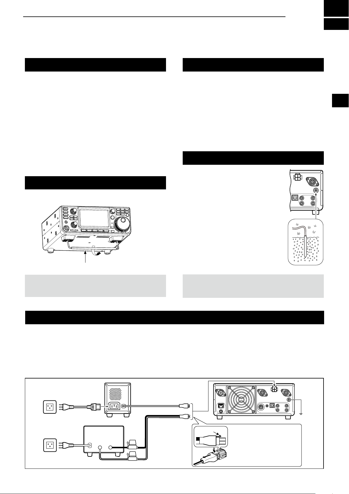
Grounding
To prevent electrical shock, television
interference (TVI), broadcast
interference (BCI) and other
problems, ground the transceiver
using the ground terminal [GND] on
the rear panel.
For best results, connect a heavy
gauge wire or strap to a long ground
rod. Make the distance between the
[GND] terminal and ground as short
as possible.
1
2
3
4
5
6
7
8
9
10
11
12
Stand
NOTE: DO NOT hold the stand, dials and controls
when you carry the transceiver. This may damage
them.
RWARNING! NEVER connect the [GND] terminal
to a gas or electric pipe, since the connection could
cause an explosion or electric shock.
Connecting an external DC power supply
Conrm that the transceiver is OFF before connecting
the DC power cable.
PS-126
AC cable
Non-Icom DC power supply
DC 13.8 V/18 A
or more
_+
PS-126
DC power cable
Fuses
Black
Supplied DC
power cable
L We recommend using Icom’s optional PS-126
(DC 13.8 V/25 A) power supply, when available.
L When connecting a non-Icom DC power cable, the
transceiver needs:
• DC 13.8 V (Capacity: At least 18 Amps)
• A power supply with an over current protective line, and
low voltage uctuation or ripple.
Locking tab
13
14
15
16
17
18
19
20
21
IC-9700
When disconnecting, rmly
push down the locking tab,
and then pull the connector
q
w
out of the socket.
GND
Red
2-1
Page 20
3
POWER
POWER
AF RF/SQL
MAIN DIAL
V/M
CALL
DR
A/B
A/B
V/M
V/M
A/B
BASIC OPERATION
When rst applying power
Before turning ON your transceiver for the rst time,
make sure all connections are correctly made.
After all connections are made, set the dials to the
positions described below.
Maximum counterclockwise
AF RF/SQL
12 oʼclock position
AF RF/SQL
TIP: When you turn OFF the transceiver, it memorizes
the current settings. Therefore, when you turn ON the
transceiver again, it restarts with the same settings.
Selecting the VFO and Memory modes
VFO mode
Set the desired frequency by rotating
Memory mode
Enter contents into the desired channel in the
MEMORY list.
Call channel mode
Call channels (or Main channel) are used to call on an
often used frequency. A Call channel is assigned on
each band.
Selecting the VFO mode or Memory mode
z Push
z Push
VFO mode (Example: VFO A)
to select the VFO or Memory mode.
to select the Call channel mode.
DR
CALL
.
Turning power ON or OFF
z To turn ON the transceiver, push
z To turn OFF the transceiver, hold down
1 second until “POWER OFF...” is displayed.
.
Adjusting the volume level
Rotate
(inner) to adjust the volume level.
for
Call Channel mode
(Example: Call channel 1)
Memory mode (Example: Memory channel 1)
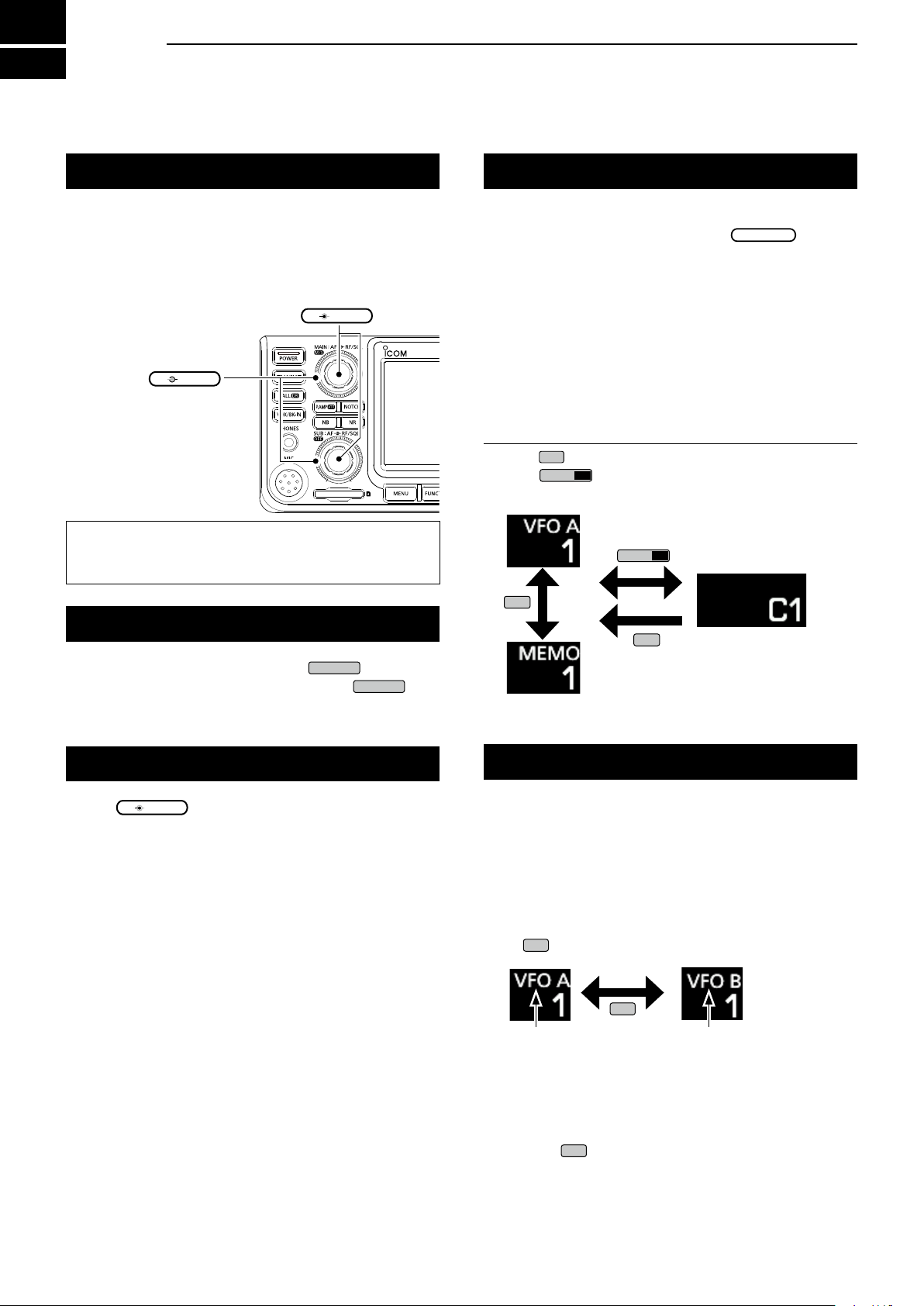
Using the VFO mode
The IC-9700 has 2 Variable Frequency Oscillators
(VFO), “A” and “B.” Having 2 VFOs is convenient to
quickly select 2 frequencies, or for split frequency
operation (p. 4-9). You can use either of the VFOs to
operate on a frequency and mode.
D Selecting VFO A or VFO B
Push
to select the VFO A or VFO B.
VFO A VFO B
D Equalizing VFO A and VFO B
You can set the displayed VFO’s frequency to the
VFO that is not displayed.
Hold down
3-1
until 2 short beeps sound.
Page 21
BASIC OPERATION
OFF
M/S
3
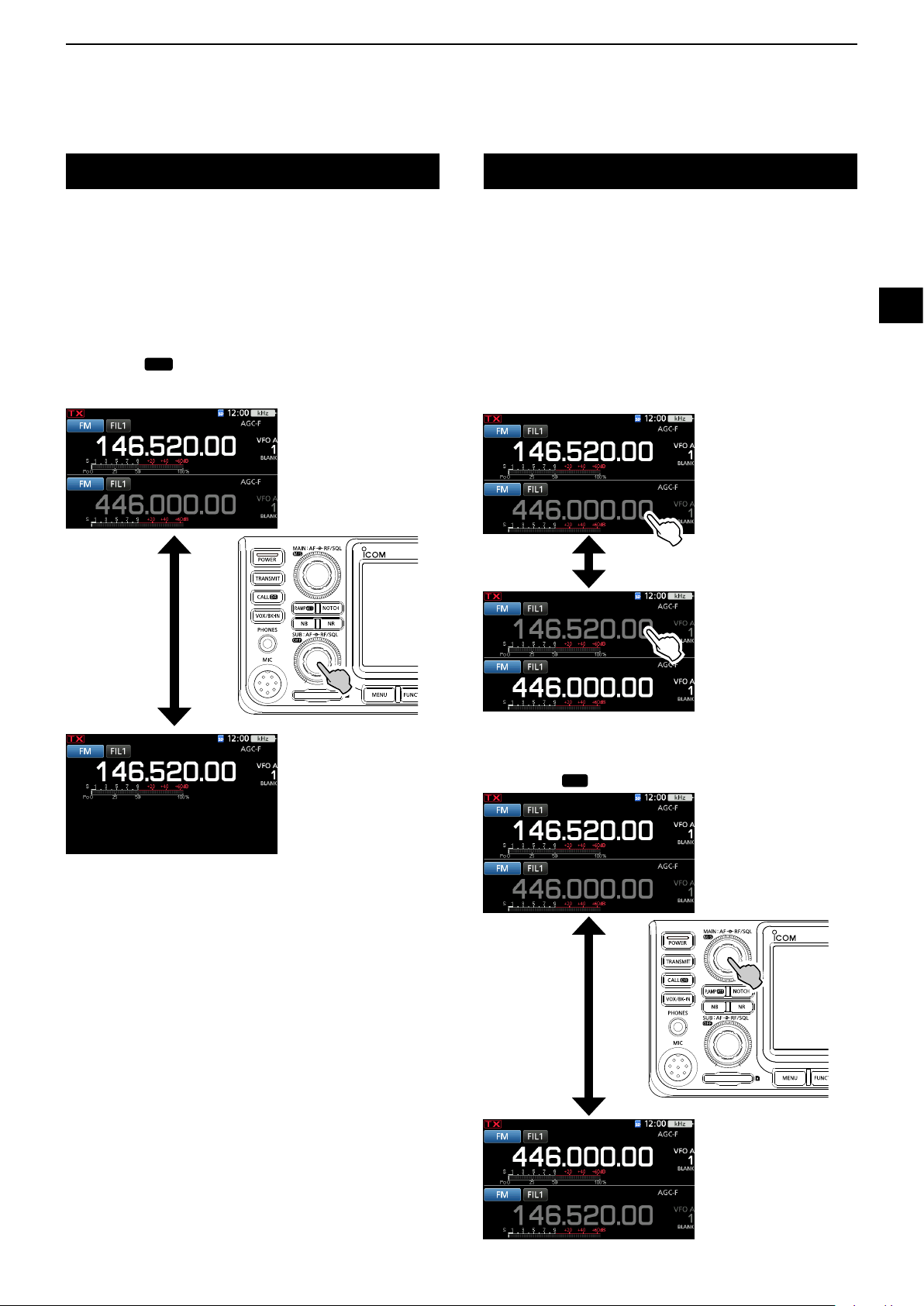
Dualwatch operation
Dualwatch simultaneously monitors two frequencies.
The IC-9700 has 2 independent receiver circuits, the
Main and Sub bands, so that you can use Dualwatch
with no compromises, even on different bands and
modes.
L The same frequency cannot be set to the both Main and
Sub bands.
Hold down
function ON or OFF.
for 1 second to turn the Dualwatch
Selecting the Main and Sub bands
The IC-9700 has 2 identical receivers, Main and Sub.
The Main band is displayed on the upper half of the
screen, and the Sub band is displayed on the lower half.
L Some functions can only be applied to the selected band,
and you can transmit on only the Main band (except in
Split Frequency operation).
To select the Main band or Sub band, touch the
grayed frequency readout.
• The selected band’s frequency readout is displayed clearly,
and the frequency of the non-selected band is grayed.
1
2
3
4
5
6
7
8
9
10
Hold down for 1 second.
D Swapping the Main band and Sub band
Hold down
for 1 second.
11
12
13
14
15
16
17
18
19
20
21
Hold down for 1 second.
3-2
Page 22
3
MENU
BASIC OPERATION
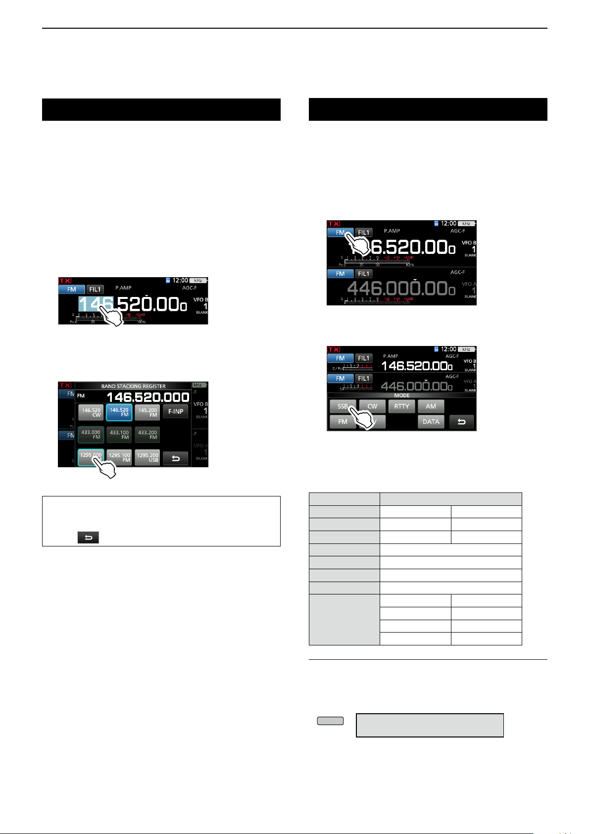
Selecting the operating band
Do the following steps to change the operating band.
Also, the band stacking register provides 3 memories
for each band key to store frequencies and operating
modes. This function is convenient to quickly recall
previously operated frequencies and modes on the
selected band.
D Using the band stacking registers
Follow the steps below to enter a register on the
selected band.
1. Touch the MHz digits. (Example: 146)
• Opens the BAND STACKING REGISTER screen.
2. Touch a band key. (Example: 1295 MHz)
L The same band cannot be set to both Main and Sub
bands.
Selecting the operating mode
You can select between the SSB (LSB/USB), SSB
data (LSB-DATA/USB-DATA), CW, CW reverse, RTTY,
RTTY reverse, AM, AM data (AM-DATA), FM, FM data
(FM-DATA), DV and DD* modes.
*Only for the 1200 MHz band
1. Touch the mode icon (example: FM).
• Opens the MODE screen.
2. On the MODE screen, touch the desired mode
key. (Example: SSB).
BAND STACKING REGISTER screen
TIP: Selecting a different Register
• Touching the band key for 1 second changes between
the 3 Registers.
• Touch
to return to the previous screen.
L In the SSB, AM or FM modes, the [DATA] key is
displayed.
• Operating mode selection list
LTouch mode key to select the operating mode.
Mode key Operating mode
[SSB] USB LSB
[CW] CW CW-R
[RTTY] RTTY RTTY-R
[AM] AM
[FM] FM
[DV]
[DD]
LSB LSB-D
[DATA]
Selecting the Data mode
You can operate data communications (SSTV, RTTY
(AFSK), PSK31, JT65B and FT8).
L When a data mode is selected, you can mute the input
from the microphone.
» SET > Connectors > MOD Input
> DATA MOD
USB USB-D
AM AM-D
FM FM-D
DV
DD
3-3
Page 23
Setting the frequency
MAIN DIAL
MAIN DIAL
BASIC OPERATION
3
D Using the Main Dial
1. Select the desired operating band. (p. 3-3)
(Example: 145 MHz)
2. Rotate
• The frequency changes according to the selected
Tuning Step.
L
is displayed when you set an amateur radio
frequency, and
when you set a frequency outside the Ham band, or
outside your set Band Edges.
.
(with dotted line) is displayed
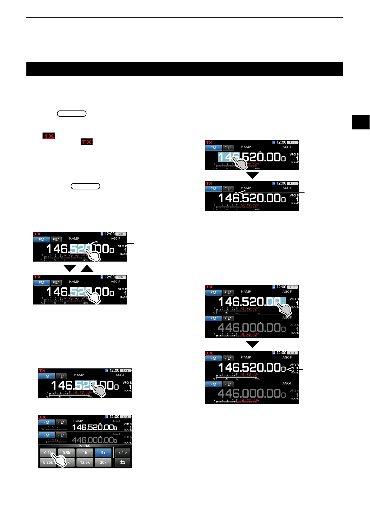
D About the Tuning Step function
You can set the
operating mode.
Touch the kHz digits to turn the Tuning Step function
ON or OFF.
L The Tuning Step function's icon “▼” is displayed above
the 1 kHz digit.
’s tuning step for each
The Tuning Step
function is ON.
D About the 1 MHz Step Tuning function
You can use the maximum tuning step of 1 MHz.
Touch the MHz digits for 1 second to turn the MHz
Step Tuning function ON or OFF.
L When using the [UP]/[DN] keys on the microphone,
the frequency changes in 1 MHz steps.
The MHz Step
function is ON.
D About the 1 Hz step Fine Tuning
function
You can use the minimum tuning step of 1 Hz for ne
tuning in the SSB, CW and RTTY modes.
Touch the Hz digits for 1 second to turn the Fine
Tuning function ON or OFF.
1
2
3
4
5
6
7
8
9
10
11
12
13
D Changing the Tuning Step
When the Tuning Step function is ON, you can change
the tuning steps for each operating mode.
1. Select the desired operating mode. (p. 3-3)
(Example: FM)
2. Touch the kHz digit for 1 second.
• The TS (FM) screen is displayed.
3. Touch the desired tuning step. (Example: 0.1 k)
• The tuning step is set and returns to the previous
screen.
The 1 Hz digit
is displayed.
L When using the [UP]/[DN] keys on the microphone,
the frequency changes in 50 Hz steps with the Fine
Tuning function ON or OFF.
14
15
16
17
18
19
20
21
3-4
Page 24
3
FUNCTION
EXIT
MAIN DIAL
EXIT
MAIN DIAL
MENU
BASIC OPERATION
Setting the frequency (Continued)
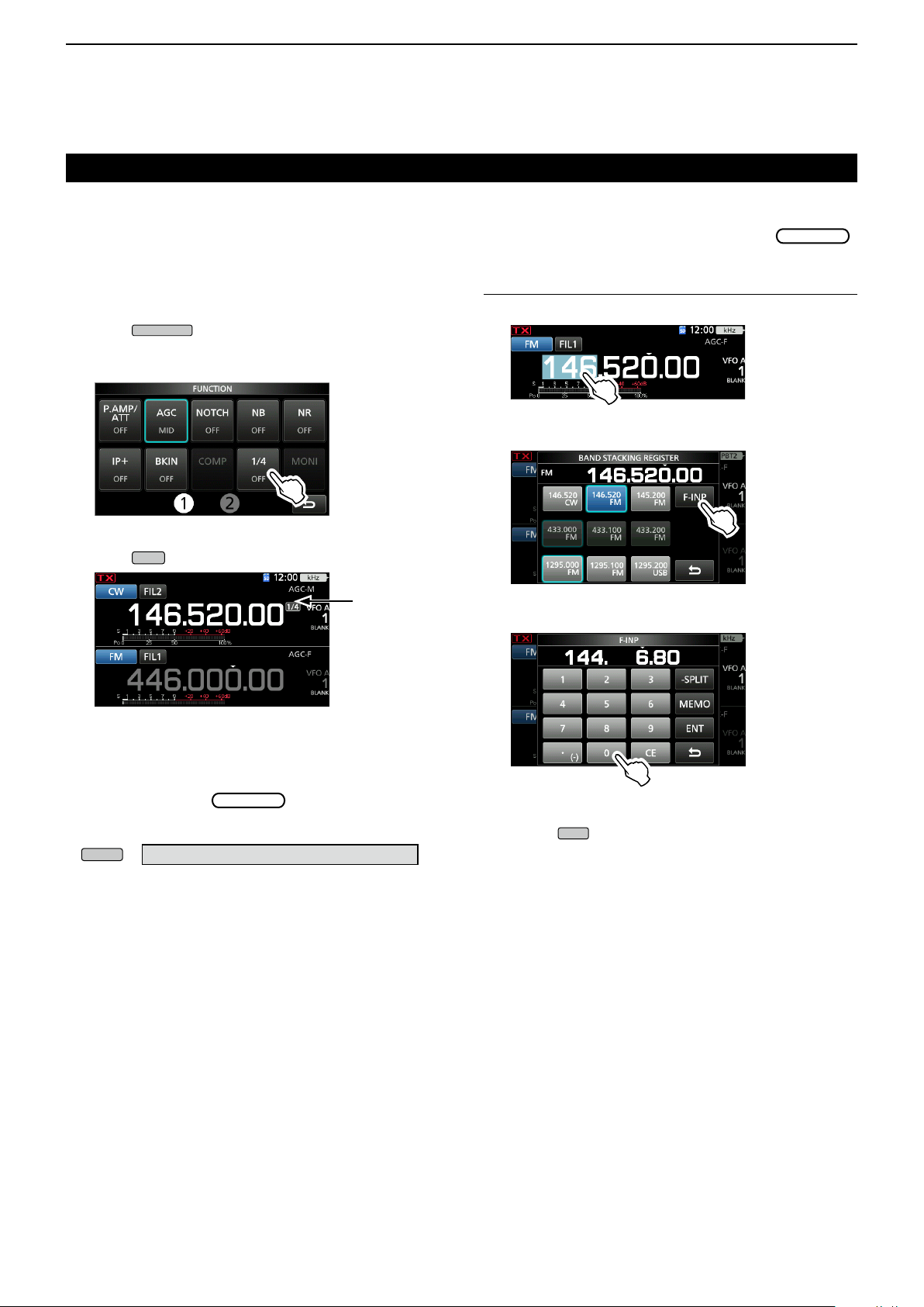
D About the 1/4 Tuning function
Mode: SSB-D/CW/RTTY
With the Tuning Function OFF, turn ON the 1⁄4 Tuning
function to reduce the tuning speed to 1⁄4 of the
normal speed, for ner tuning.
1. Push
• Opens the FUNCTION screen.
2. Touch [1/4].
FUNCTION screen
3. Push
.
.
1/4 Tuning
function
D Directly entering a frequency
You can set the frequency without rotating
by directly entering it on the keypad.
Entering the operating frequency
1. Touch the MHz digits. (Example: 146)
• Opens the BAND STACKING REGISTER screen.
2. Touch [F-INP].
• Opens the F-INP screen.
3. Start entry with the most significant digit.
D About the Auto Tuning Step function
The tuning step automatically changes, depending on
the rotating speed of
L You can change the Auto Tuning Step function settings in
the following menu. (p. 8-4)
» SET > Function > MAIN DIAL Auto TS
.
LTo clear the entry, touch [CE].
L To clear the entry and return to the previous screen,
push
.
4. Touch [ENT] to set the entered frequency.
• Closes the F-INP screen.
L If you touch [ENT] when the digits under 100 kHz are
not entered, “0” will be automatically entered into the
digits that are blank.
Entry examples
• 144.680 MHz: [1], [4], [4], [•(−)], [6], [8], [0], [ENT]
• 145.000 MHz: [1], [4], [5], [ENT]
• Changing from 144.680 MHz to 144.540 MHz:
[•(− )], [5], [4], [0], [ENT]
3-5
Page 25
Setting the frequency (Continued)
V/M
EXIT
MENU
MENU
BASIC OPERATION
3
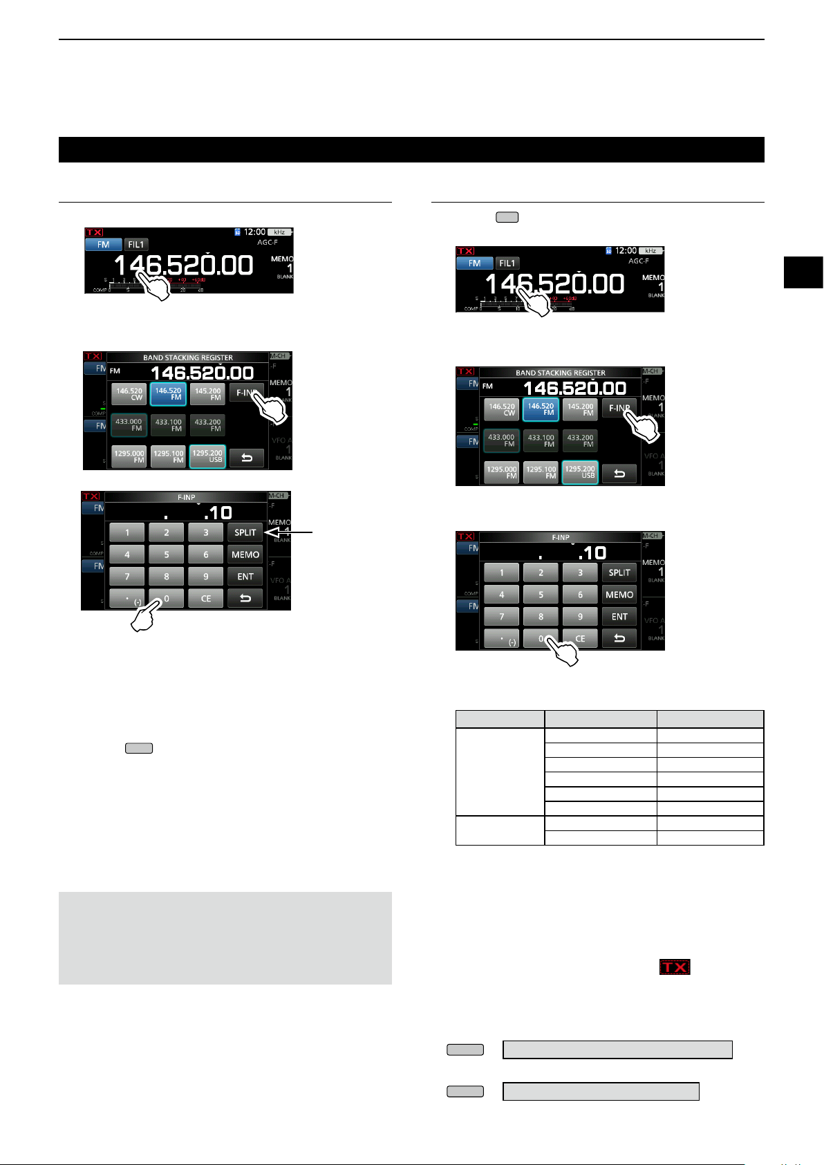
Entering the Split Frequency Offset
1. Touch the MHz digits. (Example: 146)
• Opens the BAND STACKING REGISTER screen.
2. Touch [F-INP].
• Opens the F-INP screen.
[SPLIT] or
[-SPLIT] is
displayed
Selecting a Memory channel by number
1. Touch
2. Touch the MHz digits. (Example: 146)
• Opens the BAND STACKING REGISTER screen.
3. Touch [F-INP].
• Opens the F-INP screen.
4. Enter a Memory channel number. (Example: 10)
to select the Memory mode.
1
2
3
4
5
6
7
8
9
10
11
12
3. Enter the Split Frequency Offset.
LIf you want the minus shift direction, touch [•(−)].
L Enter the offset between −9.999 MHz and +9.999
MHz (1 kHz steps).
LTo clear the entry, touch [CE].
L To clear the entry and return to the previous screen,
push
L After entering, the Split function is automatically
turned ON.
4. To save the entry, touch [SPLIT] or [−SPLIT].
• Closes the F-INP screen.
Entry examples
• 5 kHz: [5], [SPLIT]
• −10 kHz: [•(−)], [1], [0], [−SPLIT]
NOTE:
If the entered operating frequency is out of an
amateur band’s frequency range, the transmit
frequency is automatically set to the band edge
frequency.
.
L If you want to set the Program Scan Edge channel or
Call channel, enter between “100” ~ “107.”
Channel type Channel number Number to enter
1A 100
1B 101
Programming
Scan Edge
Call channel
5. Touch [MEMO] to select the memory channel of
entered number .
• Closes the F-INP screen.
• The selected memory channel contents are displayed.
2A 102
2B 103
3A 104
3B 105
C1 106
C2 107
D Band Edge Beep
You will hear a Band Edge Beep and will be
displayed when you tune into or out of an amateur
band’s frequency range.
L You can change the Band Edge Beep settings in the
following menu.
» SET > Function > Band Edge Beep
13
14
15
16
17
18
19
20
21
L If the Beep Level item is set to “0%,” no beep sounds.
» SET > Function > Beep Level
3-6
Page 26
3
MENU
Rotate
MAIN DIAL
MULTI
BASIC OPERATION
Setting the frequency (Continued)
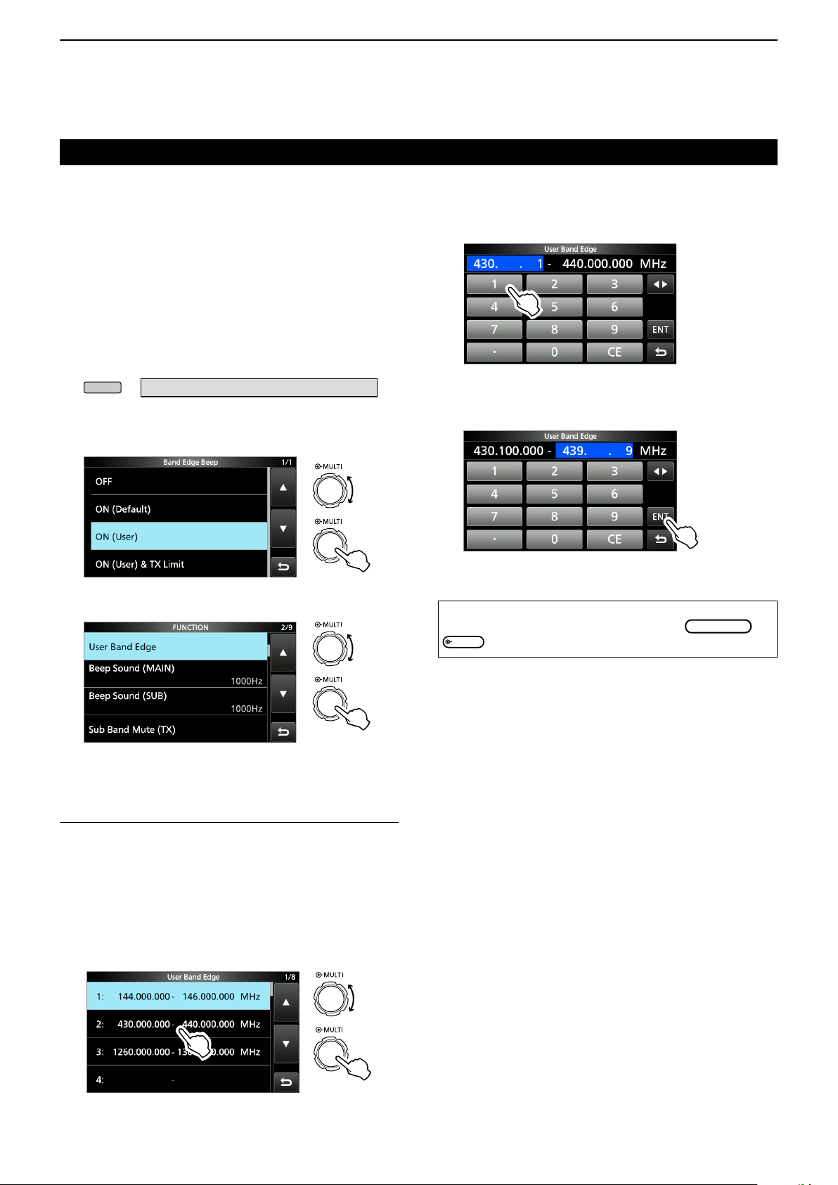
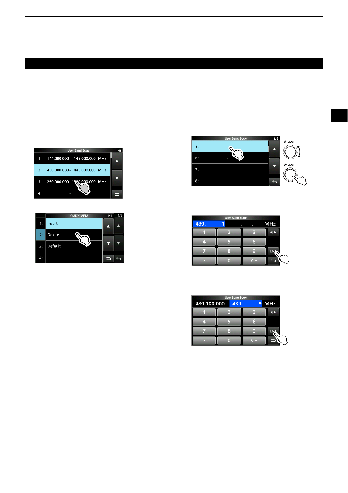
D Entering a Band Edge
When “ON (User)” or “ON (User) & TX Limit” is
selected on the “Band Edge Beep” screen, you can
enter a total of 30 band edge frequency pairs.
L Initially, all Ham band frequencies are entered into the
rst 3 band edges. Therefore, you must rst edit or delete
them to enter a new band edge.
L You cannot enter an overlapping frequency, or a
frequency that is out of the preset Ham band frequencies.
LBand edges are entered from the lower frequency rst.
1. Open the “Band Edge Beep” screen.
» SET > Function > Band Edge Beep
2. Select “ON (User)” or “ON (User) & TX Limit.”
L If you select “ON (User) & TX Limit,” you can limit
transmission to within the entered frequency range.
Rotate
Push
3. Edit the lower band edge frequency, then touch [ENT].
(Example: 430.1)
Entry example:
[•], [1], [ENT]
4. Edit the upper band edge frequency, then touch
[ENT]. (Example: 439.1)
Entry example: [4] [3] [9]
• The edited band edge is saved and returns to the
previous screen.
[•], [9], [ENT]
3. Select “User Band Edge.”
Rotate
Push
• Opens the “User Band Edge” screen.
Editing a Band Edge
You can edit a band edge entered as a default or
when entering a new band edge.
1. On the FUNCTION set screen, select “User Band
Edge.”
2. Touch the band edge you want to edit for 1
second.
(Example: 2: 430.000.000 – 440.000.000 MHz)
TIP:
You can also edit the frequency by rotating
.
or
Push
3-7
Page 27
Setting the frequency
Rotate
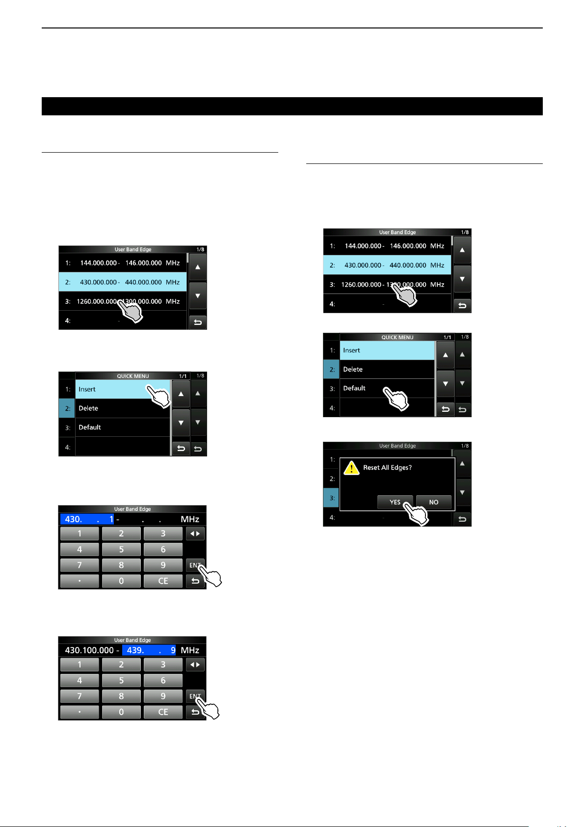
D Entering a Band Edge (Continued)
Deleting a Band Edge
To enter a new band edge, rst you must delete a
preset band edge.
BASIC OPERATION
Entering a new Band Edge
After you delete or edit the preset band edges, you
can enter a new band edge.
3
1
2
1. On the FUNCTION set screen, select “User Band
Edge.”
2. Touch the desired band edge to delete for 1
second.
(Example: 3: 1260.000.000 – 1300.000.000 MHz)
3. Touch “Delete.”
• The selected band edge is deleted and returns to the
previous screen.
1. On the FUNCTION set screen, select “User Band
Edge.”
2. Select a blank band. (Example: 5)
Push
3. Enter the lower band edge frequency
[ENT].
(Example: 430.1)
Entry example: [4] [3] [0]
4. Enter the upper band edge frequency
[ENT].
(Example: 439.9)
Entry example:
[4]
[3] [9]
[•]
[1] [ENT]
[•] [9]
[ENT]
, then touch
, then touch
3
4
5
6
7
8
9
10
11
12
13
14
15
3-8
• The entered band edge is saved and returns to the
previous screen.
16
17
18
19
20
21
Page 28
3
BASIC OPERATION
Setting the frequency
D Entering a Band Edge (Continued)
Inserting a Band Edge
After you delete or edit the preset band edges, follow
the steps below to insert a band edge.
1. On the FUNCTION set screen, select “User Band
Edge.”
2. Touch the band edge you want to insert a new
band edge above for 1 second.
(Example: 3: 1261.000.000–1300.000.000 MHz)
Resetting all band edges to presets
The steps below will reset all the band edges to their
initial settings. All entered settings will be deleted.
1. Open the “User Band Edge” screen.
2. Touch any band edge for 1 second.
3. Touch “Default.”
L The new band edge will be inserted above the
selected band edge.
3. Touch “Insert.”
4. Enter the lower band edge frequency
[ENT].
(Example: 430.1)
Entry example: [4] [3] [0]
[•]
[1] [ENT]
5. Enter the upper band edge frequency
[ENT].
(Example: 439.9)
Entry example:
[4]
[3] [9]
[•] [9]
[ENT]
then touch
, then touch
“User Band Edge” screen
• Displays “Reset All Edges?”
4. Touch [YES].
• All the band edges reset to the initial settings.
• The entered band edge is saved and returns to the
previous screen.
3-9
Page 29
BASIC OPERATION
MAIN DIAL
MULTI
TRANSMIT
MENU
AF RF/SQL
AF RF/SQL
AF RF/SQL
AF RF/SQL
AF RF/SQL
MENU
TRANSMIT
MULTI
3
RF gain and SQL level
Rotate
SQL level.
By default, rotating left (when set to the 12 o’clock
position) adjusts the RF gain, and rotating right
adjusts the squelch level, as described below.
Squelch is open
RF gain
adjustable range
is displayed
Minimum RF gain
RF gain
Adjust the RF gain to decrease the noise received
from a nearby strong station.
• Rotate counterclockwise to reduce the RF gain, which
reduces the receive sensitivity. “RFG” appears when
position. “RFG” indicates that the RF gain is reduced.
L If a strong signal is received and “OVF” (Overow)
appears, reduce the RF gain until “OVF” disappears.
SQL level
There are 2 types of SQL levels, depending on the
operating mode.
• Noise squelch
Rotate the
disappears and the TX/RX indicator goes OFF.
• S-meter squelch
The S-meter squelch disables the audio output from
the speaker or headphones when the received signal is
weaker than the specied S-meter squelch level.
Rotate the
position to increase the S-meter threshold level.
L You can change the
“RF/SQL Control.” (p. 3-10)
» SET > Function > RF/SQL Control
(outer) to adjust the RF gain and
Noise squelch (FM/DV mode)
Maximum RF gain
S-meter squelch
adjustable range
Maximum S-meter
squelch
is set to the counterclockwise from the 11 o’clock
(outer) until the noise just
clockwise from the 12 o’clock
(outer) control type in
Adjusting the transmit output
power
Before transmitting, monitor your selected operating
frequency to make sure you do not cause interference to other
stations on the same frequency. It is good amateur practice
to listen rst, and then, even if nothing is heard, ask if the
frequency in use once or twice, before you start operating.
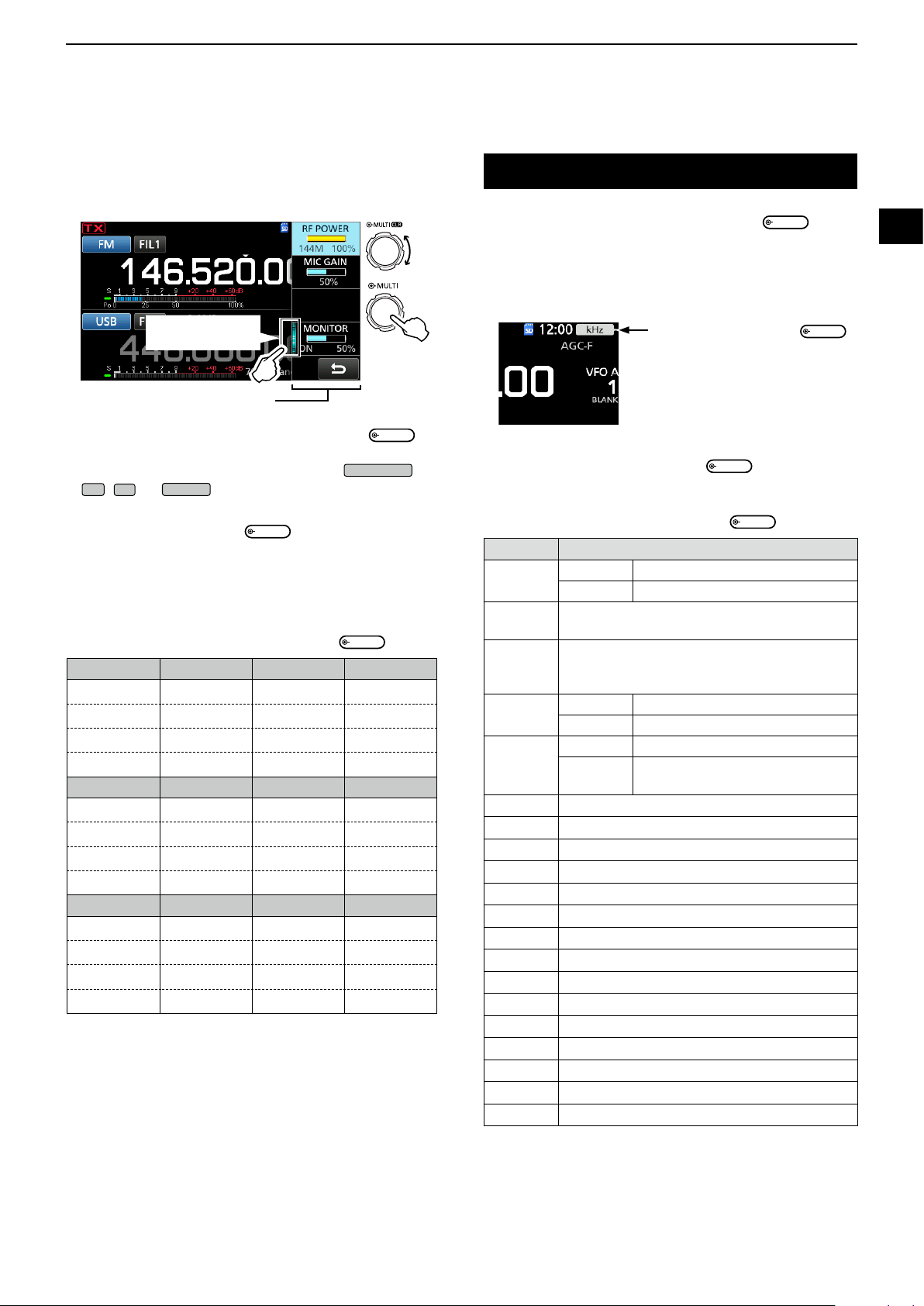
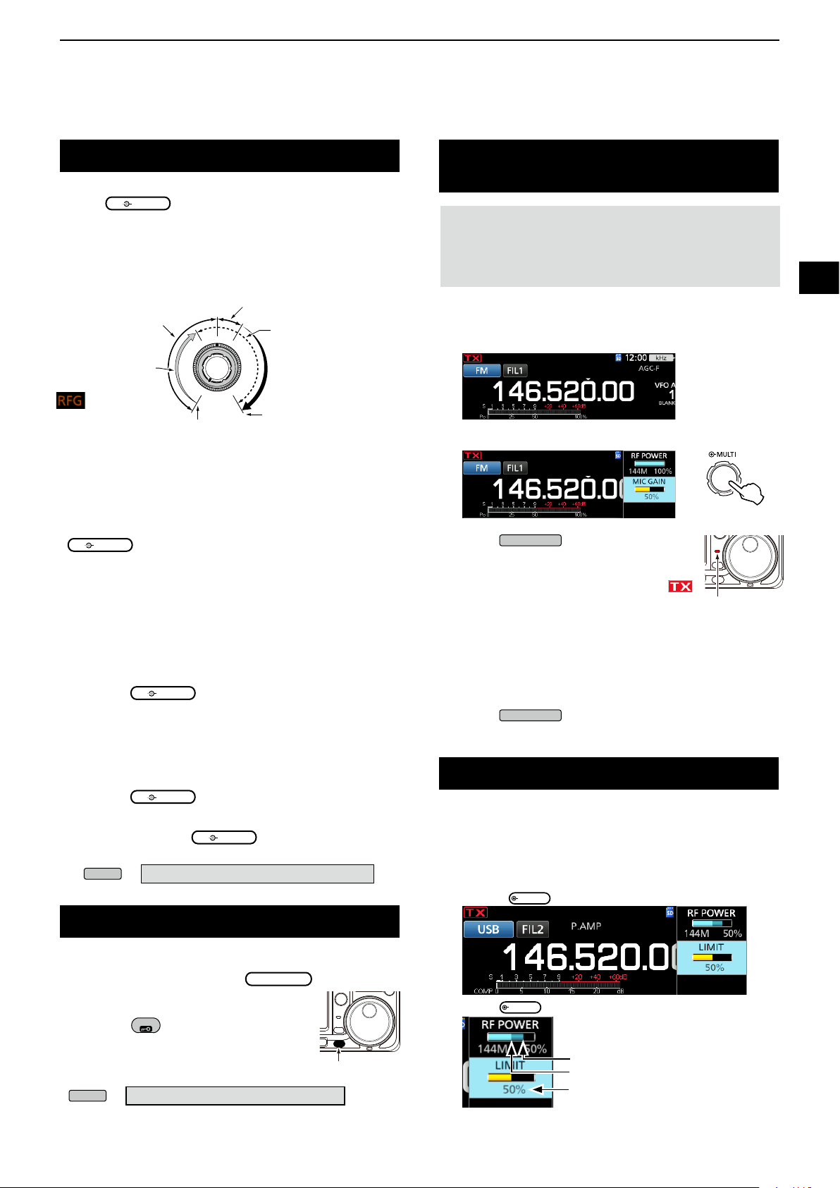
D Adjusting the transmit output power
1. Select the operating mode. (p. 3-3) (Example: USB)
2. Touch the meter to display the Po meter. (p. 3-11)
3. Open the Multi-function menu.
Push
4. Push
• The Po meter level changes according
to your voice level in the SSB mode.
• The TX/RX indicator lights red and
is displayed.
5. Touch “RF POWER.”
6. Adjust the transmit output power to between 0 and
100%.
• The Po meter displays the RF output power in a
percentage. It becomes the S-meter while receiving.
7. Push
• Returns to receive.
or hold down [PTT].
Lights red
or release [PTT].
Transmit Power Limit function
The Transmit Power Limit function limits the output
power to the preset level for each band.
1. On the FUNCTION set screen, touch [TX PWR LIMIT].
• Each touch turns the function ON or OFF.
2. Touc h [
3. Rotate
TX PWR LIMIT
to set the maximum transmit power.
] for 1 second.
1
2
3
4
5
6
7
8
9
10
11
12
13
14
15
16
17
18
19
20
Dial Lock function
The Dial Lock function prevents frequency changes
caused by accidently moving
LThis function electronically locks the dial.
Hold down
Dial Lock function ON or OFF.
• During Split Frequency operation, the Split
Lock function may be turned ON. (p. 4-10)
SPEECH
for 1 second to turn the
» SET > Function > Lock Function
.
Hold down
3-10
4. Push
21
to close the MENU.
Set transmit power
Limited transmit power (LIMIT value)
Even when set RF POWER exceeds
“LIMIT,” the actual output power is
limited to this value.
Page 30

3
Rotate
MULTI
MULTI
MULTI
BASIC OPERATION
Meter display
D Meter display selection
You can display one of the 6 different transmit
parameters (Po, SWR, ALC, COMP, VD and ID) for
your convenience.
Touch the parameter to display one of the meters.
D Multi-function meter
You can display all the parameters simultaneously.
L The TEMP meter is also displayed on the Multi-function
meter.
Hold down the parameter for 1 second to display the
Multi-function meter.
ALC meter
Adjusting the microphone gain
Adjust the microphone gain as described below.
1. Set the operating band and mode to SSB, AM, FM
or DV. (p. 3-3)
2. Push
3. Touch “MIC GAIN,” and rotate
microphone.
L Setting “50%” can be used for most voice operations,
but do following to make sure the microphone gain is
properly set.
• Hold the microphone 5 to 10 cm (2 to 4 inches) from
your mouth, then hold down [PTT] on the microphone
and speak at your normal voice level.
• In the SSB mode, touch the TX meter to select
the ALC meter, and rotate
microphone gain until the meter reading swings
between 30 to 50% of the ALC scale.
• In the AM, FM or DV mode, check the audio clarity with
another station, or use the Monitor function (p. 4-7).
to display the Multi-function menu.
to adjust the
to adjust the
ALC zone
Multi-function meter
TX inhibit zone
When the VD meter
reads on the red under
line or below, the output
power may decrease or
transceiver power may be
shut down.
S: Displays the receiving signal strength level.
Po: Displays the relative RF output power.
SWR: Displays the SWR of the antenna at the
frequency.
ALC: Displays the ALC level. When the meter
movement shows the input signal level exceeds
the allowed level, the ALC limits the RF power.
In such cases, decrease the microphone gain
level.
COMP: Displays the compression level when the
speech compressor is used.
VD: Displays the drain voltage of the nal amplier
MOS-FETs.
ID: Displays the drain current of the nal amplier
MOS-FETs.
TEMP: Displays the temperature of the nal amplier
MOS-FETs.
Displays the temperature of
the nal amplier MOS-FETs.
3-11
Page 31

RECEIVING AND TRANSMITTING
P.AMP
ATT
P.AMP
ATT
P.AMP
ATT
RIT
RIT
MULTI
RIT
RIT
Rotate
XFC
MENU
FUNCTION
AUTO
TUNE
4
Preampliers
The preamp amplies received signals in the receiver front
end to improve the signal-to-noise ratio and sensitivity. A
preamp is used when receiving weak signals.
L Each band memorizes the Preamplier setting.
Push
L Each push turns the preamplier ON or OFF.
Displayed when the preamp is used.
NOTE: When you use the preamp while receiving
strong signals, the receiving signal may be distorted.
In such case, turn OFF the preamp.
Using an external preamp
You can also use an external preamp (User supplied)
L To use an external preamp, you need to set the External
Preamplier ON or OFF for each band on the MENU
screen.
1. Push
2. Touc h [w] to change the screen.
3. Touch [EXT P.AMP].
(P.AMP).
» SET > Connectors > External P�AMP
.
RIT function
The RIT (Receive Increment Tuning) function compensates
for differences in frequencies of other stations.
The function shifts the receive frequency up to
±9.99 kHz without shifting the transmit frequency.
1. Push
• The RIT function turns ON.
L While using the Fine Tuning function (p. 3-4), the RIT
frequency is displayed in 4 digits, instead of 3.
LPushing
2. Set the RIT frequency to match the received
station’s frequency.
L You can reset the RIT frequency to “0.00” by holding
down
L You can add the frequency shift to the operating
frequency by holding down
3. After communicating, push
function OFF.
.
RIT frequency
(3 digits)
again turns OFF the RIT function.
Set the RIT
frequency.
for 1 second.
for 1 second.
to turn the RIT
1
2
3
4
5
6
7
8
9
10
11
12
13
• Each push turns the external preamp ON or OFF.
Attenuator
The Attenuator prevents a desired signal from
becoming distorted when a very strong signal is near
the frequency, or when a very strong electric eld, such
as from a broadcasting station, is near your location.
LEach band memorizes the Attenuator setting.
Hold down
Attenuator.
LPushing
L If a strong signal is received and “OVF” (Overow)
appears, turn OFF the attenuator, or reduce the RF gain
until “OVF” disappears. (p. 3-10)
Displayed when the Attenuator is ON
(ATT) for 1 second to turn ON the
turns OFF the Attenuator (no icon).
D RIT monitor function
When the RIT function is ON, you can directly monitor
the operating frequency by holding down
L While monitoring, the RIT function is temporarily OFF.
L While monitoring, the settings for the Noise Reduction,
Notch lter and Twin PBT are temporarily OFF.
D CW Auto Tuning function
CW mode
You can tune in a CW signal you are receiving using
the Auto Tuning function. You can automatically tune
by pushing
CW mode.
L During the Dual Watch mode, this function works on the
selected operational band (Main/Sub).
L While using RIT, the RIT frequency is automatically tuned
by this function.
NOTE: When receiving a weak signal, or receiving a signal
with interference, the Auto Tuning function may tune the
receiver to an undesired signal, or may not start to tune. In
such case, a warning beep sounds.
L The Auto Tuning function tunes the frequency in the IF
bandwidth.
4-1
. This function is active in only the
Displayed
while tuning
14
.
15
16
17
18
19
20
21
Page 32

4
FUNCTION
EXIT
FUNCTION
MAIN DIAL
EXIT
RECEIVING AND TRANSMITTING
AGC function control
SSB, CW, RTTY and AM modes
The AGC (Automatic Gain Control) controls receiver
gain to produce a constant audio output level, even
when the received signal strength greatly varies.
L Each band memorizes the AGC setting.
D Selecting the AGC time constant
preset value
The transceiver has FAST, MID and SLOW preset
AGC settings for all modes, except for the FM, DV
and DD modes.
1. Select the operating mode.
(Example: SSB)
2. Push
• Opens the FUNCTION screen.
3. Touch [AGC] to select the desired time constant.
L Touching [AGC] selects FAST, MID or SLOW.
LFor FM, DV and DD modes, FAST is xed.
4. To close the FUNCTION screen, push
NOTE: While you are receiving weak signals, and a strong
signal is momentarily received, the AGC function quickly
reduces the receiver gain. When that signal disappears,
the transceiver may not receive the weak signal because
of the AGC action. In that case, select FAST, or touch
[AGC] for 1 second to open the AGC screen, and then
select OFF.
.
.
D Setting the AGC time constant
You can set the preset AGC time constant to the
desired value.
1. Select the operating mode.
(Example: SSB)
2. Push
• Opens the FUNCTION screen.
3. Touch [AGC] for 1 second.
• Opens the AGC (SSB) screen.
4. Touch FAST, MID or SLOW.
(Example: MID)
5. Rotate
6. To close the AGC (SSB) screen, push
• Selectable AGC Time constant (unit: seconds)
Mode Default Adjustable time constant
LSB
USB
CW/RTTY
AM
FM 0.1
DV 0.1
DD 0.1
0.3
(FAST)
2.0
(MID)
6.0
(SLOW)
0.1
(FAST)
0.5
(MID)
1.2
(SLOW)
3.0
(FAST)
5.0
(MID)
7.0
(SLOW)
(FAST)
(FAST)
(FAST)
.
You can reset
to the default
settings by
touching this key
for 1 second.
to set the time constant.
.
OFF, 0.1, 0.2, 0.3, 0.5, 0.8, 1.2,
1.6, 2.0, 2.5, 3.0, 4.0, 5.0 or 6.0
OFF, 0.1, 0.2, 0.3, 0.5, 0.8, 1.2,
1.6, 2.0, 2.5, 3.0, 4.0, 5.0 or 6.0
OFF, 0.3, 0.5, 0.8, 1.2, 1.6, 2.0,
2.5, 3.0, 4.0, 5.0, 6.0, 7.0 or 8.0
Fixed
Fixed
Fixed
4-2
Page 33

Using the Digital Twin PBT
MULTI
MULTI
MULTI
RECEIVING AND TRANSMITTING
4
SSB, CW, RTTY and AM modes
To reject interference, the Digital Twin PBT
(Passband Tuning) narrows the IF passband width
by electronically shifting the IF frequency to slightly
above or below the IF center frequency. The IC9700 uses the digital function using the FPGA (Field
Programmable Gate Array) ltering method.
L Each band memorizes the PBT setting.
1. Push [PBT] to select “PB1.”
L Each push selects “PBT1” or “PBT2.”
“PBT1” or
“PBT2”
2. Rotate
L The passband width and shift value are displayed.
L Hold down
setting.
3. Repeat steps 1 and 2 to adjust the shift value for
“PBT2.”
to adjust the shift value.
for 1 second to clear the PBT
InformationL
• Touch the lter icon for 1 second to display the current
passband width and shift value.
• Opens the FILTER screen.
Passband
width
PBT1
PBT2
Shift
value
IF center frequency
Passband center frequency
SFT: Shift value
Passband width
BW:
1
2
3
4
5
6
7
8
9
10
11
12
InformationL
• To narrow the IF passband width, shift “PBT1” and
“PBT2” to the opposite direction from each other, to
narrow the overwrapped area.
• To shift the IF left or right, set “PBT1” and “PBT2” to the
same value.
• The PBT is adjustable in 50 Hz steps in the SSB, CW,
and RTTY modes, and 200 Hz in the AM mode. In this
case, the center shift value changes in 25 Hz steps in
the SSB, CW, and RTTY modes, and 100 Hz in the AM
mode.
NOTE: While rotating
noise. This comes from the FPGA and does not indicate an
equipment malfunction.
PBT is OFF
PBT1
PBT2
, you may hear some
Cutting
lower passband
PBT1
PBT2
Passband
Cutting both higher and
lower passbands
PBT1
PBT2
13
14
15
16
17
18
19
20
21
Passband
IF center frequency Interference Desired
signal
4-3
Interference Desired
signal
Interference
Page 34

4
MAIN DIAL
EXIT
EXIT
RECEIVING AND TRANSMITTING
Selecting the IF lter
SSB, CW, RTTY and AM modes
T
he IC-9700 has 3 IF lter passband widths for each
mode, and you can select them on the FILTER screen.
You can set the IF lter to wide (FIL 1), mid (FIL 2) or
narrow (FIL 3).
1. Select the operating mode. (Example: USB)
2. Touch the filter icon for 1 second.
• Opens the FILTER (SSB) screen.
3. Touch the filter icon several times to select FIL 1
(wide), FIL 2 (mid) or FIL 3 (narrow).
4. Touc h [B W].
• Selects the passband width mode.
5. Rotate
to select the passband width.
Touch for 1
second to reset
to default.
Mode IF lter Selectable range (steps)
FIL 1 (3.0 kHz)
SSB
SSB-D
CW
RTTY
AM
AM-D
FM
FM-D
DV
DD FIL 1 (150 kHz) Fixed
FIL 2 (2.4 kHz)
FIL 3 (1.8 kHz)
FIL 1 (3.0 kHz)
FIL 2 (1.2 kHz)
FIL 3 (500 Hz)
FIL 1 (1.2 kHz)
FIL 2 (500 Hz)
FIL 3 (250 Hz)
FIL 1 (2.4 kHz)
FIL 2 (500 Hz)
FIL 3 (250 Hz)
FIL 1 (9.0 kHz)
FIL 3 (3.0 kHz)
FIL 1 (15 kHz)
FIL 3 (7.0 kHz)
FIL 1 (15 kHz)
FIL 3 (7.0 kHz)
50 Hz to 500 Hz (50 Hz)/
600 Hz to 3.6 kHz (100 Hz)
50 Hz to 500 Hz (50 Hz)/
600 Hz to 3.6 kHz (100 Hz)
50 Hz to 500 Hz (50 Hz)/
600 Hz to 3.6 kHz (100 Hz)
50 Hz to 500 Hz (50 Hz)
600 Hz to 2.7 kHz (100 Hz)
200 Hz to 10.0 kHz (200 Hz)FIL 2 (6.0 kHz)
FixedFIL 2 (10 kHz)
FixedFIL 2 (10 kHz)
L You cannot change the passband width in the FM,
FM-D, DV or DD mode.
L When you change the passband width, the Digital
Twin PBT setting value is reset to the center position.
L “BPF” is displayed when a band width less than 500
Hz is selected in the SSB, CW or RTTY mode.
6. To close the FILTER screen, push
.
Selecting the IF lter shape
SSB, CW, RTTY and AM modes
You can set the IF lter shape for each operating mode.
1. Select the operating mode. (Example: USB)
2. Touch the filter icon for 1 second.
3. Opens the FILTER screen.
4. Touch the filter icon several times to select FIL1
(wide), FIL2 (mid) or FIL3 (narrow).
TIP: When you set the IF lter to FIL2 or FIL3 in the FM
mode, the transceiver will transmit in the FM narrow mode.
• SHARP
This selection is to emphasize the passband width of
the lter. The lter has an almost ideal shape factor.
Signals that are out of the passband are extremely
ltered out, and it gives you better audio quality.
• SOFT
The lter shoulders are roundly formed as in analog
lters. This decreases noise components in the
high and low frequencies of the lter passband,
and increases the S/N of the target signal. These
characteristics play an effective role in picking up
very weak signals in the 50 MHz band, for example.
The shape factor is kept, and the sharpness of the
bandpass is excellent.
When [SOFT] is selected
5. Touch [SHARP] or [SOFT].
6. To close the FILTER screen, push
.
4-4
Page 35

Noise Blanker
NB
MULTI
MULTI
RECEIVING AND TRANSMITTING
4
SSB, CW, RTTY and AM modes
The Noise blanker eliminates pulse-type noise such
as the noise from car ignitions.
Push
NOTE: When using the Noise Blanker, received signals
may be distorted if they are excessively strong, or the
noise is other than a pulse type. In that case, turn OFF the
Noise Blanker, or shallow the DEPTH on the NB menu.
See the description below for details.
to turn the Noise Blanker ON or OFF.
Displayed when
the Noise Blanker
is ON
D Adjusting the NB level and time
To deal with various type of noise, you can adjust the
attenuation level and blanking depth and width in the
NB menu.
1. Hold down NB for 1 second.
• Turns ON the Noise Blanker and opens the NB menu.
2. Touch the item to adjust. (Example: DEPTH)
Rotate
Push
NB is OFF
Pulse-type
noise
Desired signal
NB is ON
(DEPTH is too short)
Noise
still exists
Desired signal
Portion of desired signal is also removed
LEVEL (Default: 50%)
Adjust the level where the Noise Blanker activates
between 0 and 100%.
DEPTH (Default: 8)
Adjust the noise attenuation level to between 1 and 10.
WIDTH (Default: 50)
Adjust the blanking duration time to between 1 and 100.
NB is ON (Effective)
NB LEVEL
NB WIDTH
NB is ON
(WIDTH is too wide)
Noise removed
Desired signal
Desired signal
1
2
3
4
5
6
7
8
9
10
11
12
13
14
3. Rotate
4. Push
to adjust the item. (Example: 8)
to close the NB menu.
15
16
17
18
19
20
21
4-5
Page 36

4
NR
MULTI
Rotate
NOTCH
NOTCH
NOTCH
MULTI
EXIT
EXIT
RECEIVING AND TRANSMITTING
Noise Reduction
SSB, CW, RTTY, AM, FM and DV modes
The Noise Reduction function reduces random noise
components and enhances signal audio.
Push
OFF.
D Adjusting the Noise Reduction level
Adjust the Noise Reduction level to where noise is
reduced but the received signal is not distorted.
1. Hold down NR for 1 second.
2. Rotate
to turn the Noise Reduction function ON or
Displayed
when the Noise
Reduction
function is ON
• Turns ON the Noise Reduction function and opens the
NR menu.
to adjust the Noise Reduction
level to between 0 and 15.
L Adjust to a higher level to increase the reduction
level, and a lower level to decrease it.
Notch Filter
SSB, CW, RTTY, AM and FM modes
The IC-9700 has Auto Notch and Manual Notch
functions.
Auto Notch automatically attenuates beat tones,
tuning signals and so on. It can be used in the SSB,
AM and FM modes.
Manual Notch attenuates beat tones, tuning signals
and so on by manually adjusting the ltering
frequency. It can be used in the SSB, CW, RTTY and
AM modes.
D Selecting the Notch lter type
Push
or “MN (Manual Notch).”
L Pushing
“MN (Manual Notch)” and OFF.
several times to select “AN (Auto Notch)”
changes between “AN (Auto Notch),”
Displayed when
a notch lter is
selected
3. To close the NR menu, push
Noise Reduction OFF
NR level 0
Noise components Desired signal (CW)
Noise Reduction ON
.
NR level 4
Push
D Setting the Manual Notch lter
When Manual Notch is selected, adjust the ltered
frequency.
1. Hold down
NOTCH menu.
• Opens the Notch menu.
• The Manual Notch is automatically selected and “MN”
is displayed.
2. Touch [WIDTH] several times to select the Manual
Notch filter width from “WIDE,” “MID” and “NAR.”
3. Rotate
frequency.
4. To close the NOTCH menu, push
NOTE: While adjusting, noise may be heard.
This comes from the FPGA and does not indicate an
equipment malfunction.
for 1 second to display the
slowly, to manually attenuate the
.
4-6
Page 37

RECEIVING AND TRANSMITTING
FUNCTION
MULTI
EXIT
FUNCTION
EXIT
4
Monitor function
The Monitor function enables you to monitor your
transmit audio. Use this function to check the
voice characteristics while adjusting transmit audio
parameters.
L You can hear the CW sidetone regardless of the Monitor
function setting.
1. Select the operating mode that you want to
monitor. (Example: USB)
2. Push
• Opens the FUNCTION screen.
3. Touch [MONI] to turn ON the Monitor function.
LTouching [MONI] turns the Monitor function ON or OFF.
4. If you want to adjust the monitor audio output,
touch [MONI] for 1 second.
5. Rotate
audio output between 0% and 100%, while
speaking at your normal voice level.
.
to adjust
MONITOR to the clearest
Rotate
Push
IP Plus function
The IP Plus function improves the Intermodulation
Distortion (IMD) quality by exerting the direct sampling
system performance.
This function optimizes the Analog/Digital Converter
(ADC) against the distortion when you receive a
strong input signal. It also improves the Third-order
Intercept Point (IP3) while minimizing the reduction of
the receive sensitivity.
1. Push
• The FUNCTION screen is displayed.
2. Touch [IP+].
LTouch [IP+] to turn the IP Plus function ON or OFF.
L Select ON to prioritize the IP quality, and select OFF
to prioritize the receive sensitivity.
3. To close the FUNCTION screen, push
.
.
1
2
3
4
5
6
7
8
9
10
11
12
13
14
15
6. To close the NOTCH menu, push
NOTE: When using the VOX function, turn OFF the
Monitor function. Otherwise the transmitted audio will
echo.
.
16
17
18
19
20
21
4-7
Page 38

4
FUNCTION
EXIT
MULTI
FUNCTION
EXIT
RECEIVING AND TRANSMITTING
Setting the Speech Compressor
SSB mode
The Speech Compressor increases the average RF
output power, improving readability at the receiving
station. This function compresses the transmitter
audio input to increase the average audio output level.
L The function is effective for long-distance communication,
or when propagation conditions are poor.
D Setting before using the Speech
Compressor function
1. Select the SSB mode.
(Example: USB)
2. Push
• Opens the FUNCTION screen.
3. Be sure the Speech Compressor is OFF.
L If it is ON, touch [COMP] to turn it OFF.
.
OFF
D Using the Speech Compressor function
1. Touch the Multi-function meter again to display
the COMP meter.
2. Push
• Opens the FUNCTION screen.
3. Touch [COMP] to turn it ON.
4. Touch [COMP] for 1 second.
5. While speaking into the microphone at your
normal voice level, adjust the Speech Compressor
level to where the COMP meter reads within the
COMP zone (10 to 20 dB range).
L If the COMP meter peaks exceed the COMP zone,
your transmitted voice may be distorted.
Speech Compressor is ON
COMP zone
6. To close the COMP menu, push
.
Rotate
.
4. Push
to close the FUNCTION screen.
5. Touch the Multi-function meter to display the ALC
me ter.
L Touching the Multi-function meter sets the meter to
Po, SWR, ALC, COMP, V
ALC meter
6. Push
to display the Multi-function menu.
D or ID.
7. Touch [MIC GAIN], and then adjust it by speaking
into the microphone to where the ALC meter
reads within the 30 to 50% range of the ALC zone.
ALC zone
4-8
Page 39

Split frequency operation
SPLIT
XFC
XFC
A/B
SPLIT
SPLIT
A/B
RECEIVING AND TRANSMITTING
4
Split frequency operation enables you to transmit and
receive on different frequencies in the same band.
The other station My station
Transmit frequency
Receive frequency
USB mode
146.540 MHz
USB mode
146.560 MHz
VFO A
Receive frequency
VFO B
Transmit frequency
D Using the Quick Split function
The Quick Split function enables you to automatically
equalize the frequency and mode of VFOs to the
displayed VFO, and activate the Split function.
1. Set VFO A’s receive frequency and operating
mode.
(Example: 146.540 MHz in the USB mode)
2. Hold down
• The Quick Split function is turned ON and the VFO A
settings are set to VFO B.
Displayed
for 1 second.
There are 2 ways to use Split frequency operation.
• Use the Quick Split function
• Use the receive and transmit frequencies set to VFO
A and VFO B.
D Using the receive and transmit
frequencies set to VFO A and VFO B
1. Set VFO A’s receive frequency and operating
mode.
(Example: 146.540 MHz in the USB mode)
2. Push
frequency and the operating mode.
(Example: 146.560 MHz in the USB mode)
to select VFO B, and then set the receive
1
2
3
4
5
6
7
8
9
10
11
12
13
14
15
3. While holding down
frequency offset between transmit and receive.
(Example: 20.00 kHz)
, set the operating
The offset
between
transmit and
receive while
holding down
16
3. Push
L Pushing
to turn ON the Split function.
turns the Split function ON or OFF.
Displayed
17
18
19
20
.
21
4. Push
LThe Split frequency operation is ready.
4-9
to return to VFO A.
Page 40

4
XFC
MAIN DIAL
MENU
SPEECH
XFC
FUNCTION
MENU
MENU
MENU
MENU
MULTI
MULTI
RECEIVING AND TRANSMITTING
Split Lock function
To prevent accidentally changing the receive
frequency by releasing
while rotating
use the Split Lock function. Using both this function
and the Dial Lock function enables you to change only
the transmit frequency.
1. Turn ON the Split Lock function.
» SET > Function > SPLIT > SPLIT LOCK
2. Turn ON the Split function.
3. Hold down
for 1 second to turn ON the Dial
Lock function.
4. While holding down
, set the transmit
frequency.
Setting the transmit lter width
SSB mode
The transmit lter width for the SSB and SSB-D
modes can be set. Only for the SSB mode, WIDE
(wide), MID (middle) or NAR (narrow) can be selected.
Operating CW
D Setting the CW pitch control
,
You can set the received CW audio pitch and the CW
side tone to suit your preference without changing the
operating frequency.
1. Select the CW mode.
2. Display the Multi-function menu.
Push
3. Touch [CW PITCH].
4. Set the CW pitch to between 300 and 900 Hz (in
5 Hz steps).
5. Push
to close the Multi-function menu.
To change the lter width in the SSB mode:
1. Set the operating mode to USB or LSB.
2. Push
• Opens the FUNCTION screen.
.
3. Touc h [T BW].
L Touching [TBW] sets the lter width to WIDE, MID or
NAR.
The transmit lter widths are set to the following
values by default.
• SSB (WIDE): 100 Hz to 2900 Hz
• SSB (MID): 300 Hz to 2700 Hz
• SSB (NAR): 500 Hz to 2500 Hz
• SSB-D: 300 Hz to 2700 Hz
L You can change the lter width values in the following
settings.
SET > Tone Control/TBW > TX > SSB > TBW (WIDE)
»
SET > Tone Control/TBW > TX > SSB > TBW (MID)
»
SET > Tone Control/TBW > TX > SSB > TBW (NAR)
»
SET > Tone Control/TBW > TX > SSB-D > TBW
»
D Setting the key speed
You can set the keying speed of the internal electric keyer.
1. Select the CW mode.
2. Display the Multi-function menu.
Push
3. Touch [KEY SPEED].
4. Set the key speed to between 6 and 48 Words Per
Minute (WPM).
5. Push
to close the Multi-function menu.
4-10
Page 41

Operating CW (Continued)
VOX/BK-IN
VOX/BK-IN
Rotate
VOX/BK-IN
MULTI
EXIT
VOX/BK-IN
VOX/BK-IN
MENU
RECEIVING AND TRANSMITTING
4
D Using the Break-in function
Use the Break-in function in the CW mode to
automatically switch between transmit and receive
when keying. The IC-9700 is capable of Semi Break-in
and Full break-in modes.
TIP: The key type is set to “Paddle” by default. You can
select the keyer type on the CW-KEY SET screen. (p. 4-12)
Semi Break-in operation
In the Semi Break-in mode, the transceiver transmits
when keying, and then automatically returns to receive
after a preset time after you stop keying.
1. Select the CW mode.
2. Push
L Pushing
“F-BKIN (Full Break-in)” or OFF (no indication).
Semi Break-in
3. To adjust the Break-in delay time, hold down
• Opens the BKIN menu.
4. Set to where the transceiver does not return to
receive while keying.
to display “BKIN.”
selects “BKIN (Semi Break-in),”
for 1 second.
Full Break-in operation
In the Full Break-in mode, the transceiver
automatically transmits while keying down, and then
immediately returns to receive after keying up.
1. Select the CW mode.
2. Push
L Pushing
“F-BKIN (Full Break-in)” or OFF (no indication).
Full Break-in
3. Use a straight key or paddle.
L In the Full break-in mode, the transceiver
automatically returns to receive without a preset
break-in delay time after you stop keying. The
transceiver receives while keying up.
several times to select “F-BKIN.”
selects “BKIN (Semi Break-in),”
D Monitoring the CW side tone
When the transceiver is in standby and the Break-In
function is OFF, you can listen to the CW side tone
without actually transmitting.
1
2
3
4
5
6
7
8
9
10
11
12
13
14
L When you are using a paddle, push
the Multi-function menu, and then adjust the KEY
SPEED (p. 4-10) while operating the paddle.
5. To close the BKIN menu, push
.
to display
InformationL
• This enables you to match your transmit frequency
exactly to another station’s by matching the audio tone.
• You can also use the CW side tone (make sure the
Break-in function is OFF (p. 8-7)) to practice CW
sending.
• You can adjust the CW side tone level in “Side Tone
Level.”
» KEYER > EDIT/SET > CW-KEY SET >
Side Tone Level
15
16
17
18
19
20
21
4-11
Page 42

4
MENU
EXIT
Rotate
EXIT
RECEIVING AND TRANSMITTING
Operating CW (Continued)
D About the electronic Keyer function
You can set the Keyer Memory function settings,
paddle polarity settings, and so on of the Electronic
Keyer.
1. Select the CW mode.
2. Open the KEYER screen.
» KEYER
3. Touch [EDIT/SET].
• Opens the EDIT/SET screen.
EDIT
KEYER MEMORY edit menu
You can edit the Keyer memories
M1 to M8.
KEYER screen
4. Select the desired item to set.
EDIT/SET screen
5. To close the KEYER screen, push
times.
Push
several
001 SET
CW-KEY SET
KEYER 001 contest number
menu
You can set the following items.
• Number Style
• Count Up Trigger
• Present Number
CW-KEY SET menu
You can set the following items.
• Side Tone Level
• Side Tone Level Limit
• Keyer Repeat Time
• Dot/Dash Ratio
• Rise Time
• Paddle Polarity
• Key Type
• MIC Up/Down Keyer
4-12
Page 43

Spectrum scope screen
MENU
HOLD
MAIN DIAL
SCOPE OPERATION
5
The spectrum scope enables you to display the
activity on the selected band, as well as the relative
strengths of various signals.
The transceiver has two spectrum scope modes, the
Center mode and the Fixed mode.
You can also turn the Waterfall display ON or OFF.
In addition, you can select the Mini scope to display it
in a smaller size on the screen.
• Center mode screen
Span (Display range)
MAIN/SUB band icon
Center/Fixed mode icon
Span (Display range)
Operating frequency (stays on Center)
Waterfall zone
(FFT: Fast Fourier Transform)
• Fixed mode screen
MAIN/SUB band icon
Center/Fixed mode icon
Edge (Lower frequency)
Operating frequency (moves)
Waterfall zone
Grid (frequency/level)
FFT scope zone
Edge (Upper frequency)
Grid (frequency/level)
FFT scope zone
D Marker
The Marker displays the operating frequency in the
SPECTRUM SCOPE screen.
: The RX marker displays the re-
ceive frequency.
: The TX marker displays the trans-
mit frequency.
• About RX Marker
In the Fixed mode, the RX Marker displays the
operating frequency within a specied frequency
range. So, the transceiver always displays the RX
marker in the scope screen.
In the Center mode, the operating frequency stays on
the Center of the screen. Thus, the transceiver does
not display the RX Marker.
L When the Hold function is ON, the RX Marker is displayed
to indicate the operating frequency’s position.
D Using the Spectrum Scope
Display the SPECTRUM SCOPE screen.
»
SCOPE
MAIN/SUB band icon*
MENU 1: Center mode
MENU 1: Fix mode
MENU 2: Center/Fix mode
* Touch the MAIN/SUB band icon selects the displayed band.
Key Action
< 1 >
< 2 >
SPAN
EDGE
HOLD
CENT/FIX Selects the Center or Fixed mode.
EXPD/
SET
REF
SPEED
MARKER Selects the Marker.
Selects the Function menus.
In the Center mode, selects the
Touch
Touch for
1 second
In the Fixed mode, selects the Edge
frequencies.
L You can set the upper and lower edge
frequencies in the “Fixed Edges” item on
the SCOPE SET screen by touching [EXPD/
SET] for 1 second.
Touch
Touch for
1 second
Touch
Touch for
1 second
Opens the Reference level window.
L Rotate
level.
L Touch again to close the window.
Selects the sweep speed.
• “” (FAST), “” (MID), or “” (SLOW).
scope span.
• Spans: ±2.5, 5.0, 10, 25, 50, 100,
250 and 500 kHz
Resets to the ±2.5 kHz span.
Sets the Hold function to ON or
OFF.
• “
Clears the Peak Hold level.
Selects the Expanded or Normal
screen.
Displays the SCOPE SET screen.
” and the Marker are
displayed. Freezes the current
spectrum.
to adjust the Reference
1
2
3
4
5
6
7
8
9
10
11
12
13
14
15
16
17
18
19
20
21
5-1
Page 44

5
MENU
MENU
XFC
MENU
M.SCOPE
M.SCOPE
SCOPE OPERATION
Spectrum scope screen (Continue)
D Center mode
Displays signals around the operating frequency
within the selected span. The operating frequency is
always displayed in the center of the screen.
1. Display the SPECTRUM SCOPE screen.
»
SCOPE
2. Touch [CENT/FIX].
L Touch [CENT/FIX] to toggle between the Center and
Fixed modes.
3. Touch [SPAN] several times to select the scope
span.
• ±2.5, 5.0, 10, 25, 50, 100, 250 and 500 kHz
L Touch [SPAN] for 1 second to select the ±2.5 kHz
span.
–2.5 kHz
Center mode
+2.5 kHz
D Fixed mode
Displays signals within a specied frequency range.
The selected frequency band activity can easily be
observed in this mode.
Three Fixed Edge bands can be set for each amateur
frequency band covered by the transceiver in the
SCOPE SET screen.
D Touch screen operation
When you touch the FFT scope zone or the waterfall
zone in the SPECTRUM SCOPE screen, the area
will be zoomed in. Then you touch the signal in the
zoomed area, you can directly tune your frequency to
the signal in the SPECTRUM SCOPE screen.
L Holding down
1. Display the SPECTRUM SCOPE screen.
»
2. Touch the Scope screen.
• The area around the touched point is zoomed in.
3. Touch the signal in the zoomed area.
InformationL
• In the Center mode, the operating frequency
changes to the touched point, and the point moves to
the screen center.
• In the Fixed mode, the operating frequency and
marker change to the touched point.
• Touch out of the zoomed area to close the zoomed
window.
changes the transmit frequency.
SCOPE
1. Display the SPECTRUM SCOPE screen.
»
SCOPE
2. Touch [CENT/FIX].
L Touch [CENT/FIX] to toggle between the Center and
Fixed modes.
3. Touch [EDGE] several times to select the Edge
frequency.
L When the operating frequency moves outside
the upper or lower edge frequency, “<<” or “>>”
is displayed in the upper side corners of the
SPECTRUM SCOPE screen.
<<: The frequency is outside the lower edge.
>>: The frequency is outside the higher edge.
When the frequency goes further away, “Scope Out
of Range” is displayed.
145.800 MHz
Fixed mode
146.000 MHz
D Mini scope screen
The Mini scope screen can be simultaneously displayed
with another function displays, such as the RTTY
DECODE screen and the AUDIO SCOPE screen.
L The Mini scope screen cannot be used when the Dualwatch
function is ON.
Push
L Hold down
SPECTRUM SCOPE screen.
Mini scope screen with the AUDIO SCOPE screen
5-2
to turn the Mini scope screen ON or OFF.
for 1 second to display the
Page 45

Audio scope screen
MENU
HOLD
MENU
EXIT
MULTI
MULTI
SCOPE OPERATION
5
This audio scope enables you to display the received
signal’s frequency component on the FFT scope, and
its waveform components on the Oscilloscope. The
FFT scope also has an waterfall.
Display the AUDIO SCOPE screen.
»
AUDIO
AUDIO SCOPE screen
Key Action
Selects the attenuator for the FFT
Touch
ATT
Touch for
1 second
Sets the Hold function to ON or OFF.
HOLD
LEVEL
TIME
EXPD/
SET
• AUDIO SCOPE screen
MAIN/SUB band icon*
• “
audio spectrum.
Selects the Oscilloscope level.
• 0, –10, –20, or –30 dB
Selects the Oscilloscope sweep time.
• 1, 3, 10, 30, 100, or 300 ms/Div
Touch
Touch for
1 second
scope.
• 0 (OFF), 10, 20, or 30 dB
Turns OFF the attenuator. (0 dB)
” is displayed and freezes the current
Selects the Expanded or Normal
screen.
Enters the AUDIO SCOPE SET
screen.
D AUDIO SCOPE SET screen
This screen is used to set the FFT scope waveform
type, color, Waterfall display and oscilloscope
waveform color.
1. Display the AUDIO SCOPE screen.
»
AUDIO
2. Touch [SET].
3. Touch to select the item to set.
(Example: “FFT Scope Waveform Type”)
4. Touch the option to set.
L See below for details on the setting items and their
options.
5. To close the AUDIO SCOPE SET screen, push
.
TIP: You can set each item to its default by touching
the item for 1 second, and then touching “Default” on
the QUICK MENU.
FFT Scope Waveform Type (Default: Fill)
Select the type of waveform for the FFT scope.
• Line: Only the waveform outline is drawn.
• Fill: The full waveform is drawn in color.
FFT Scope Waveform Color
(Default: (R) 51 (G) 153 (B) 255)
Set the waveform color for the FFT scope.
L Touch and select the R (Red), G (Green) or B (Blue)
scale, and then rotate
to 255.
L The color is displayed in the box above the RGB scale.
FFT Scope Waterfall Display (Default: ON)
Turn the Waterfall display ON or OFF.
• OFF: Turns OFF the Waterfall display.
• ON: Turns ON the Waterfall display.
to adjust the ratio from 0
1
2
3
4
5
6
7
8
9
10
11
12
13
14
15
16
17
18
19
20
21
OscilloscopeWaterfall zone
FFT Scope zone
*Touching the MAIN/SUB band icon selects the displayed band.
Oscilloscope Waveform Color
(Default: (R) 0 (G) 255 (B) 0)
Set the waveform color for the Oscilloscope.
L Touch and select the R (Red), G (Green) or B (Blue)
scale, and then rotate
to 255.
L The color is displayed in the box above the RGB scale.
5-3
to adjust the ratio from 0
Page 46

6
MENU
EXIT
SD CARD
SD cards and SDHC cards are not supplied by Icom.
They are user supplied.
TIP: Icom recommends that you save the
transceiver’s factory default data for backup.
About the SD cards
You can use an SD card of up to 2 GB, or an SDHC of
up to 32 GB. Icom has checked the compatibility with
the following SD and SDHC cards.
(As of February 2019)
Brand Type Memory size
SanDisk
L The above list does not guarantee the card’s
performance.
L Throughout the rest of this document, the SD cards and
SDHC cards are simply called the SD card or the card.
NOTE:
• Before using the SD card, thoroughly read the
instructions that came with the card.
• If any of the following occur, the card's data may be
corrupted or deleted.
- You remove the card from the transceiver while it is still
accessing the card.
- A power failure occurs, or the power cable is
disconnected, while accessing the card.
- You drop, impact or vibrate the card.
• Do not touch the contacts of the card.
• The transceiver may take a longer time to recognize a
high capacity card.
• The card has a certain lifetime, so data reading or writing
may not be possible after using it for a long period of
time.
If reading or writing data is impossible, the card’s lifetime
may have ended. In that case, use a new one.
We recommend that you make a separate backup le of
the important data onto your PC.
• Icom will not be responsible for any damage caused by
data corruption on an SD card.
®
SD 2 GB
SDHC 4/8/16/32 GB
Inserting
Insert the SD card as shown below.
L Insert the SD card into the slot until it locks in place, and
makes a ‘click’ sound.
L Be sure to check the card orientation before inserting.
LOCK
SD
Beveled corner
NOTE:
Before using an SD card for the rst time, be
sure to format it in the transceiver�
• Formatting a card erases all its data.
• Before formatting any used card, back up its data onto
your PC.
• After inserting or formatting, a special folder on the card
that you need for operations like updating the rmware is
created on the card.
IMPORTANT: Even if you have formatted an SD
card, some data may remain in the card. When you
dispose the card, be sure to physically destroy it to
avoid unauthorized access to any data that remains.
Formatting
Before using an SD card, format it to be used with the
transceiver by doing the following steps.
1. Open the SD CARD screen.
» SET > SD Card
2. Touch “Format.”
Saving data
You can save the following data onto the card.
• Data settings and Memory channel contents of the
transceiver
• Communication/receive log and contents
• Automatic answering voice audio in the DV mode
• Voice audio for the Voice TX function
• RTTY decode log
• Captured screens
• Your (UR) call sign memory
• Repeater List
• GPS memory
3. Touch [YES] to start formatting.
• After formatting, returns to the SD CARD screen.
LTo cancel formatting, touch [NO].
4. To close the SD CARD screen, push
times.
6-1
several
Page 47

SD CARD
MENU
EXIT
MENU
EXIT
Unmounting Saving the setting data
6
Before you remove a card when the transceiver is ON,
be sure to electrically unmount it, as shown below.
Otherwise the data may be corrupted or deleted.
1. Open the SD CARD screen.
» SET > SD Card
2. Touch “Unmount.”
3. Touch [YES] to unmount.
The Memory channels and the transceiver’s settings
can be saved onto an SD card.
1. Open the SAVE SETTING screen.
» SET > SD Card > Save Setting
2. Touch “<<New File>>.”
L The le name is automatically set in the following
format: Setyyyymmdd_xx (yyyy: Year, mm: month,
dd: day, xx: serial number).
3. To save the file with the displayed name, touch
[ENT].
1
2
3
4
5
6
7
8
9
10
11
12
• After unmounting, returns to the SD CARD screen.
LTo cancel unmounting, touch [NO].
4. Remove the card from the transceiver.
q Push in
w Pull out
L Push in the SD card until a click sounds to unlock the
card, and then pull it out.
5. To close the SD CARD screen, push
times.
When the transceiver is OFF
You can remove the SD card starting from step 4 of
the steps described above.
several
L If you want to change the name, delete the name and
reenter it, and then touch [ENT].
4. Touch [YES].
• Saves the data settings.
5. To close the SD CARD screen, push
times.
several
13
14
15
16
17
18
19
20
21
6-2
Page 48

6
MENU
SD CARD
Loading the saved data
You can load the Memory channels and transceiver’s
settings from the SD card to the transceiver.
1. Open the LOAD SETTING screen.
» SET > SD Card > Load Setting
2. Touch the file to load
3. Touch “Select.”
L If you want to load all the contents on the LOAD
OPTION screen, touch “ALL” and go to step 6.
L If you want to load only the repeater list, touch
“Repeater List Only” and go to step 6.
4.
Touch the loading options. (Example: CI-V Address)
6. Touch [YES] or [NO].
• “Keep 'SKIP' settings in the Repeater List?” is
displayed.
L When you touch [YES], the skip settings of the
repeater list are retained.
L When you touch [NO], the skip settings of the
repeater list are cleared.
7. Touch [YES].
• After the loading ends, “COMPLETED! Restart the
IC-9700.” is displayed.
L When you select “REF Adjust” in step 4, “The new
"REF Adjust" setting will be saved” is displayed.
8. Turn OFF the transceiver power, then turn it ON
again to restart the transceiver.
• “✓” is displayed left side of the selected option.
L The Set mode settings and Memory channel
contents are always loaded.
5. Touch “<<Load>>.”
6-3
Page 49

SD CARD
MENU
EXIT
EXIT
MENU
EXIT
6
Deleting a data le
Follow the steps below to delete the les you no
longer need on the SD card.
NOTE: Deleted data from a card cannot be recalled.
Before deleting any data, back up the card data onto
your PC.
1. Open the SAVE SETTING screen.
» SET > SD Card > Save Setting
2. Touch the file to delete for 1 second.
3. Touch “Delete.”
Displaying the card information
You can display the SD card capacity, and the time
remaining for voice recording.
1. Open the SD CARD screen.
» SET > SD Card
2. Touch “SD Card Info.”
1
2
3
4
5
6
7
8
9
10
11
LTo delete all les, touch “Delete All.”
LTo cancel deleting, push
4. Touch [YES].
5. To close the SET screen, push
times.
Checking the le information
Touch “File Information” on the QUICK MENU to
display the le name, size and the saved date.
.
several
3. To close the SET screen, push
times.
several
12
13
14
15
16
17
18
19
20
21
6-4
Page 50

6
MENU
SD CARD
Importing or Exporting a CSV format le
Please read this section before importing or exporting
a Comma Separated Values (CSV) format le from the
SD card.
You can import or export the following data:
• Your Call Sign Memory
• Repeater List
• GPS Memory
D Importing
1. Open the IMPORT/EXPORT screen.
» SET > SD Card > Import/Export
2. Touch “Import.”
3. Touch the data to import. (Example: Your Call Sign)
NOTE:
• Before importing, make a backup le of all the
transceiver’s data to the SD card in case of data
loss.
• The transceiver cannot display a le that has a
le name longer than 21 characters. In this case,
rename it using 20 characters or less. When you
export the data in a CSV format le using the
CS- 9700, BE SURE to name it using 20 characters
or less.
5. Touch [YES].
• Starts to import.
LAfter importing ends, “COMPLETED!” is displayed.
LTo complete the importing, restart the transceiver.
TIP: To import a repeater list, see the ADVANCED
MANUAL for details.
4. Touch the CSV file to import.
6-5
Page 51

Importing or Exporting a CSV format le (Continued)
MENU
EXIT
SD CARD
6
D Exporting
1. Open the IMPORT/EXPORT screen.
» SET > SD Card > Import/Export
2. Touch “Export.”
3. Touch the data to export. (Example: Your Call Sign)
4. Touch “<<New File>>.”
5. To save the file with the displayed name, touch
[ENT].
L If you want to change the name, delete the name and
reenter it, and then touch [ENT].
6. Touch [YES].
7. To close the EXPORT screen, push
times.
several
1
2
3
4
5
6
7
8
9
10
11
12
13
L
The le name is automatically set in the following
format: Your*yyyymmdd_xx (yyyy: Year, mm: month,
dd: day, xx: serial number).
* “Rpt” is displayed for a repeater list, and “Gps” is
displayed for a GPS memory.
14
15
16
17
18
19
20
21
6-6
Page 52

6
SD CARD
About the SD card folders
You can easily restore data with a backup le, even if
the setting data in the SD card is accidentally deleted.
IC-9700 Capture
Csv RptList
Decode
QsoLog
Reply
RxLog
Setting
Voice
VoiceTx
GpsMemory
YourMemory
Rtty
yyyymmdd
yyyymmdd
The folder in the SD card contains the following.
• IC-9700 folder
The folders created in the IC-9700 are contained in
this folder.
• Capture folder
Saves the captured screen data in the “png” or
“bmp” format.
• Csv folder
Contains the GPS Memory, Repeater List and Your
Call Sign Memory folders.
• GpsMemory folder
Saves the Gps Memory in the “csv” format to import.
• RptList folder
Saves the Repeater List in the “csv” format to import.
• YourMemory folder
Saves the Your Call Sign Memory in the “csv” format
to import.
• Decode folder
Saves the RTTY decode log.
• Rtty folder
Saves the transmitted or received RTTY decode log
data in the “txt” or “html” format.
• QsoLog folder
Saves QSO log data in the “csv” format.
• Reply folder
Saves Automatic reply data in the “wav” format.
• RxLog folder
Saves RX record log data in the “csv” format.
• Setting folder
Saves the transceiver’s setting data in the “icf”
format.
• Voice folder
Creates the recorded QSO audio date folders.
• yyyymmdd folder
Saves the recorded audio le in the “wav” format.
The folder name is automatically created in the
following format:
yyyymmdd (yyyy: year, mm: month, dd: day)
• VoiceTx folder
Saves the recorded voice audio data for the Voice
TX function in the “wav” format.
6-7
Page 53

SATELLITE COMMUNICATION
MENU
MAIN DIAL
MAIN DIAL
MAIN DIAL
MAIN DIAL
MAIN DIAL
7
Satellite communications outline
Both Satellite Mode B (435 MHz uplink, 145 MHz
downlink), Mode J (145 MHz uplink, 435 MHz
downlink) and Mode L (1270 MHz uplink, 435 MHz
downlink) can be operated.
Preamplier (user supplied) may help receiving weak
signals.
Satellite information:
Satellite information describes satellite location, orbit
angles, and so on. Such information may be available in
ham magazines, organization publications or on web sites.
Satellite tracking software is also convenient.
FUJI 3 (FO-29)
Uplink
Downlink
145 MHz band 145 MHz band
435 MHz
band
435 MHz
band
D Setting the satellite VFO
1. Touch [MAIN].
• The Main band is selected.
2. Rotate
3. Touch [SUB].
• The Sub band is selected.
to set the downlink frequency.
1
2
3
4
5
6
7
8
9
10
Mode V/U operating diagram
[Example]: FUJI 3 (FO-29), Mode V/U
Uplink frequency: 145.9000–146.0000 MHz
Downlink frequency: 435.8000–435.9000 MHz
Tracking direction: Reverse
CW beacon frequency: 435.7950 MHz
Selecting the satellite mode
Operating frequencies in the satellite mode can be
selected either before or after selecting the mode.
Normal and reverse tracking are selectable.
Enter the Satellite mode in the MENU.
» SATELLITE
• Touch [SATELLITE] for 1 second, to copy the current
frequency to the Satellite VFO.
L When the DR or DD mode is selected, the frequency is
not copied.
L
Touch [SATELLITE] for 1 second again, to exit the Satellite mode.
Downlink (receive)
frequency
4. Rotate
to set the uplink frequency.
D Selecting NOR/REV tracking
Touching [NOR REV] changes the frequency
increment when rotating
.
11
12
13
14
15
16
17
18
19
20
21
Uplink (transmit)
frequency
Key Function
MAIN Touch to select the Main band (Downlink frequency).
NOR
Change the tracking.
REV
SUB Touch to select the Sub band (Uplink frequency).
• NOR: Both downlink and uplink frequencies
simultaneously increase or decrease in the same
steps when you rotate
• REV: The downlink frequency follows the tuning dial
rotation, however, the uplink frequency changes in
the reverse direction to the
7-1
the same steps.
.
rotation, in
Page 54

7
MENU
MAIN DIAL
MAIN DIAL
MAIN DIAL
SATELLITE COMMUNICATION
Loop test procedure
Decide on a usable satellite, and point your antenna
towards it.
L Monitored audio may cause howling. Using headphones
is recommended.
1. Set the downlink frequency (receive frequency) in
the Main band to match the beacon frequency.
L The beacon frequency drifts (Doppler effect). Rotate
to adjust the frequency.
2. When you can receive the beacon, rotate
to select a frequency within the
satellite’s coverage, as the downlink frequency on
the MAIN band.
About the Loop test:
Loop test is a method to conrm the communication status
between your station and the satellite. By transmitting your
voice (Example: your call sign), check the received audio.
5. While rotating
, speak at your normal
voice level to the microphone.
• Adjust the uplink frequency so that your voice is
clearly heard.
6. Touch [SUB].
• The Sub band is unselected.
Using the spectrum scope
You can visually check the signal presence on the
Spectrum Scope screen.
» SCOPE
L Select a vacant frequency within the satellite’s
coverage. Monitor the operating frequency to make
sure transmitting won’t cause interference to other
stations.
3. Push [PTT] on the microphone to transmit. (or
push [TRANSMIT] on the transceiver)
4. Touch [SUB].
• The Sub band is selected.
L By touching on the waterfall zone on the SPECTRUM
SCOPE screen, you can directly tune your frequency on
the displayed area of the band.
LRefer to Section 5 for details on the Scope screen.
About the Doppler effect:
Since the speed of satellite is high, the uplink and downlink
frequency appear to drift due to the Doppler effect.
As the satellite is moving towards your station, the
downlink or uplink frequency appears to be higher, and is
lower as the satellite is moving away. Therefore, you need
to precisely adjust the uplink or downlink frequency to
compensate for the frequency drift.
7-2
Page 55

SATELLITE COMMUNICATION
MAIN DIAL
MAIN DIAL
Satellite operation Satellite memories
7
When your own signal can be received with a loop
test, satellite communication can be performed.
1. Rotate
2. When a frequency is shifted by the Doppler effect,
rotate
• When you use beam antennas, you may need critical
adjustment of the antenna direction, especially when
communicating through satellites in low orbits.
Using the RIT
You can tune the downlink frequency ±9.99 kHz with
the RIT. (p. 4-1)
Communicating in the FM mode:
• Some satellites require the transmit signal with a
tone when communicating in the FM mode. Refer
to amateur radio websites for more information.
• The AFC function automatically compensates for
the frequency drift caused by the Doppler effect. (p.
7-2)
Communicating in the FM mode:
You can have a QSO with the crew of the ISS
(International Space Station) using the Split function. Refer
to related websites for more information.
to set the frequency.
to tune to the frequency.
The IC-9700 has 99 satellite memories to store both
uplink and downlink frequencies,
operating modes and other data.
L Tracking selection, normal or reverse, is not programmed
in the satellite memories.
L Refer to the ADVANCED MANUAL for memory
management details.
1 2 3 4
5
D Satellite memory screen
q Satellite memory number (1 ~ 99)
w Downlink frequency
The downlink frequency (Receive frequency) and
mode.
e Uplink frequency
The uplink frequency (Transmit frequency) and
mode.
r Memory edit icon
Touch to open the MEMORY menu. You can edit
the memory name, write or clear the memory in the
menu.
t Memory name
The saved memory name is displayed.
L Select a memory, then push [QUICK] to open the QUICK
MENU. You can edit the memory name,
the memory in the menu.
write or clear
1
2
3
4
5
6
7
8
9
10
11
12
13
14
15
16
17
18
19
20
21
7-3
Page 56

8
MENU
MULTI
EXIT
EXIT
QUICK
EXIT
SET MODE
Set mode description
You can use the Set mode to set infrequently changed
values or function settings.
1. Push
2. Touch [SET].
.
TIP: The Set mode is constructed in a tree structure.
You may go to the next tree level, or go back a
level, depending on the selected item.
5. Touch the item to open the item’s setting screen,
or to open its next tree level.
LTo go back the previous tree level, push
6. Touch to select or to set the option.
• The selected option is set, and returns to the previous
screen.
.
3. Touch the category that you want to select.
4. Push [▲] or [▼] to scroll through the items.
L You can also rotate
items.
to scroll through the
7. To close the SET screen, push
TIP: Resetting to the default setting
1. Push
2. Touch “Default” to reset to the default setting.
LTo close the Quick menu, push
to display the QUICK MENU screen.
several times.
.
8-1
Page 57

SET MODE
MENU
MENU
MENU
MENU
8
Tone Control/TBW
» SET > Tone Control/TBW > RX
SSB, AM, FM, DV, CW, RTTY
RX HPF/LPF (Default: – – – – – – – – –)
Sets the cut-off frequencies for the receive audio high-
pass lter and low-pass lter, in 100 Hz steps.
L If this item is set, the “RX Bass” and “RX Treble” items are
automatically set to “0.”
SSB, AM, FM, DV
RX Bass (Default: 0)
RX Treble (Default: 0)
Sets the bass or treble level of the receive audio.
» SET > Tone Control/TBW > TX
SSB, AM, FM, DV
TX Bass (Default: 0)
TX Treble (Default: 0)
Sets the bass or treble level of the transmit audio.
SSB
TBW (WIDE) (Default: 100 – 2900)
TBW (MID) (Default: 300 – 2700)
TBW (NAR) (Default: 500 – 2500)
Sets the transmission passband width to wide, mid,
or narrow, by changing the lower and higher cut-off
frequencies.
SSB-D
TBW (Default: 300 – 2700)
Sets the transmission passband width by changing
the lower and upper cut-off frequencies.
Function
» SET > Function
Beep Level (Default: 50%)
Sets the beep output level.
L If the “Beep (Conrmation)” item is set to “OFF,” no beeps
sound.
Beep Level Limit (Default: ON)
Selects whether or not to limit the volume up to the
specied level.
• OFF: Does not limit the volume level.
• ON: Limits the volume level.
Beep (Conrmation) (Default: ON)
Turns the Conrmation beep ON or OFF.
• OFF: Turns the function OFF for silent operation.
• ON: A beep sounds when a switch is pushed or
the touch panel is touched.
L If the “Beep Level” item is set to “0%,” no beep sounds.
Band Edge Beep (Default: ON (Default))
Selects an option for the Band Edge Beep function.
• OFF: Turns OFF the function.
• ON (Default): A beep sounds when you tune outside
of, or back into the default amateur
band’s frequency range.
• ON (User): A beep sounds when you tune outside
of, or back into a user programmed
amateur band’s frequency range.
• ON (User) & TX Limit:
A beep sounds when you tune outside
of, or back into a user programmed
amateur band’s frequency range.
Transmitting is inhibited outside of the
range.
L If the “Beep Level” item is set to “0%,” no beep sounds
Beep Sound (MAIN) (Default: 1000Hz)
Beep Sound (SUB) (Default: 1000Hz)
Sets the audio frequency for beeps.
L If the “Beep Level” item is set to “0%,” no beep sounds.
.
1
2
3
4
5
6
7
8
9
10
11
12
13
14
15
16
17
18
19
20
» SET > Function > Sub Band Mute (TX)
Speaker/Phones (Default: OFF)
USB (Default: OFF)
LAN (Default: OFF)
Selects whether or not to mute the received audio of
the SUB band when you transmit.
• OFF: Does not mute the received audio of the SUB
band.
• ON: Mutes the received audio of the SUB band.
8-2
21
Page 58

8
MENU
AF RF/SQL
MENU
MENU
MENU
SET MODE
Function (Continued)
» SET > Function
RF/SQL Control (Default: RF+SQL)
Sets the
(outer) control operation.
• Auto: Functions as an RF gain control in the
SSB, CW and RTTY modes.
Functions as a squelch control in the AM,
FM, DV, and DD modes.
• SQL:
Functions as a squelch control in all modes.
Does not function as an RF gain control.
• RF+SQL: Functions not only as an RF gain control,
but also as a squelch control in all modes.
When using as an RF gain/squelch control
Noise squelch (FM/DV mode)
Squelch is open
RF gain
adjustable range
is displayed
Minimum
RF gain
S-meter squelch
adjustable range
Maximum
RF gain
Maximum
S-meter squelch
» SET > Function > TX Delay
144M (Default: OFF)
430M (Default: OFF)
1200M (Default: OFF)
Sets the TX delay time on the 144, 430, or 1200 MHz
band.
L If an external equipment’s rise time is slower than that
of the IC-9700, a reected wave is produced and it may
damage the IC-9700 or the external device. To prevent
this, set the appropriate delay time so that no reected
wave, or timing damage occurs.
LSelect “OFF” for no rise speed.
Rx
SEND
Tx
Po
0 10
Delay time (ms)
» SET > Function
Time-Out Timer (Default: OFF)
Sets the Time-out Timer to OFF, 3, 5, 10, 20, or
30 minutes to prevent an accidental prolonged
transmission.
LSelect “OFF” for no time limit.
When using as an RF gain control
(Squelch is xed open: SSB, CW, RTTY only)
Maximum RF gain
RF gain
adjustable range
is displayed
Minimum
RF gain
Maximum
RF gain range
When using as a squelch control
(RF gain is xed at maximum.)
Noise squelch (FM mode)
Noise squelch
threshold
Squelch is open
S-meter squelch
threshold
S-meter squelch
adjustable range
Maximum
S-meter squelch
FM/DV Center Error (Default: ON)
Turns the FM/DV Center Error indication ON or OFF.
The MAIN/SUB band indicator shows the received
signal deviation.
When an off-center signal is received, the indicator
blinks green.
• OFF: Turns OFF the function.
• ON: Turns ON the function.
PTT Lock (Default: OFF)
Turns the PTT Lock function ON or OFF.
To prevent accidental transmissions, this function
inhibits all transmissions.
• OFF: Turns OFF the function.
• ON: Inhibits all transmissions.
» SET > Function > SPLIT
Quick SPLIT (Default: ON)
Turns the Quick SPLIT function ON or OFF.
This function automatically turns ON the SPLIT
function, and set the frequency and mode that is not
displayed (VFO A or AFO B), according to the SPLIT
Offset setting.
• OFF: Turns OFF the function.
• ON: Turns ON the function.
SPLIT Offset (Default: 0.000 MHz)
Sets the SPLIT offset between -9.999 and +9.999 MHz.
The SPLIT offset is the difference between the receive
and transmit frequencies for the Quick SPLIT function.
8-3
Page 59

SET MODE
MENU
XFC
MAIN DIAL
MENU
MENU
SPEECH
SPEECH
MENU
SPEECH
SPEECH
SPEECH
SPEECH
SPEECH
MAIN DIAL
AF RF/SQL
AF RF/SQL
POWER
SPEECH
MAIN DIAL
MAIN DIAL
8
» SET > Function > SPLIT
SPLIT LOCK (Default: OFF)
Turns the Split Lock function ON or OFF.
The SPLIT LOCK function enables you to adjust the
transmit frequency while holding down
while the Dial Lock function is activated.
To prevent accidentally changing the receive
frequency by rotating
LOCK and Dial Lock functions (p. 3-10).
• OFF: Turns OFF the function.
• ON: Turns ON the function.
» SET > Function
Auto Repeater (Default: ON)
The Auto repeater function automatically turns the
duplex operation and tone encoder ON or OFF.
LThis item is displayed only in the USA version.
• OFF: Turns OFF the function.
• ON (DUP):
• ON (DUP, TONE): Turns ON the duplex settings and
RTTY Mark Frequency (Default: 2125)
Selects the RTTY mark frequency.
L When the internal RTTY decoder is used, 2125 Hz is
automatically selected.
RTTY Shift Width (Default: 170)
Selects the RTTY shift width.
L When the internal RTTY decoder is used, 170 Hz is
automatically selected.
RTTY Keying Polarity (Default: Normal)
Selects the RTTY keying polarity.
• Normal: Key open/close = Mark/Space
• Reverse: Key open/close = Space/Mark
» SET > Function > SPEECH
SPEECH Language (Default: English)
Sets the speech language to English or Japanese.
Alphabet (Default: Normal)
Selects the alphabet characters announcement.
SPEECH Speed (Default: Fast)
Sets the speech speed to Fast or Slow.
RX Call Sign SPEECH (Default: ON (Kerchunk))
Turn the RX Call Sign Speech function ON or OFF for
calls received in the DV mode.
RX>CS SPEECH (Default: ON)
Turn the RX>CS Speech function ON or OFF.
Turns ON the duplex settings only.
the tone encoder function.
, use both the SPLIT
, even
S-Level SPEECH (Default: ON)
Turns the S-meter level announcement ON or OFF.
• OFF:
• ON: The signal strength level, the operating mode
MODE SPEECH (Default: OFF)
Turns the operating mode announcement ON or OFF.
• OFF:
• ON: The selected operating mode is announced.
SPEECH Level (Default: 50%)
Sets the Voice Synthesizer audio output level.
[SPEECH/LOCK] Switch (Default: SPEECH/LOCK)
Selects
• SPEECH/LOCK: Pushing
• LOCK/SPEECH: Pushing
Lock Function (Default: MAIN DIAL)
This function electronically locks
panel display* to prevent accidental changes.
* Keys and dials are also locked except for
Memo Pad Quantity (Default: 5)
Sets the number of memo pad channels.
MAIN DIAL Auto TS (Default: High)
Sets the Auto Tuning Step function for
When rapidly rotating
automatically changes according to the rotation speed.
• OFF: Auto tuning step is turned OFF.
• Low: Approximately two times faster.
• High: Approximately ve times faster when the
MIC Up/Down Speed (Default: Fast)
Selects the steps per second when changing
an operating frequency by holding down the
microphone’s [UP]/[DN] key.
• Slow: Low speed (25 tuning steps/second)
• Fast: High speed (50 tuning steps/second)
The operating mode and the operating
frequency are announced when you push
and the operating frequency are announced
when you push
The selected operating mode is not announced.
» SET > Function
action.
Synthesizer function.
Holding down
function ON or OFF.
function ON or OFF.
Holding down
Voice Synthesizer function.
,
tuning step is set to 1 kHz or smaller.
Approximately two times faster when the
tuning step is set to 5 kHz or larger.
, and
.
turns ON the Voice
turns the Lock
turns the Lock
turns ON the
or the
,
.
.
, the tuning step
.
1
2
3
4
5
6
7
8
9
10
11
12
13
14
15
16
17
18
19
20
21
8-4
Page 60

8
MENU
MENU
POWER
POWER
POWER
MENU
SET MODE
Function (Continued)
» SET > Function
AFC Limit (Default: ON)
Select whether to limit the operating range of the AFC
(Automatic Frequency Control) function, or not.
• OFF: Turns OFF the function.
• ON:
Limits the operating range of the AFC function.
The limit value differs depending on the IF
lter width as described below.
IF Filter width AFC limit value
15 kHz ±10 kHz
10 kHz ±7 kHz
7 kHz ±5 kHz
[NOTCH] Switch (SSB) (Default: Auto/Manual)
[NOTCH] Switch (AM) (Default: Auto/Manual)
Selects the notch function used in the SSB or AM mode.
• Auto: Only the Auto Notch function can be
used.
• Manual: Only the Manual Notch function can
be used.
• Auto/Manual: Both the Auto and Manual Notch
functions can be used.
Screen Capture [POWER] Switch (Default: OFF)
Assigns the Screen Capture function to
• OFF:
does not act as the Screen Capture
key.
• ON:
acts as the Screen Capture key.
Screen Capture File Type (Default: PNG)
Sets the le format for the Screen Capture function to
PNG or BMP.
» SET > Function > REF Adjust
REF Adjust
Adjusts the internal reference frequency.
REF Adjust (FINE)
Fine tune the value set in “REF Adjust.”
NOTE: The default setting of “REF Adjust” may differ
slightly, depending on the transceiver’s version.
My Station
» SET > My Station
.
SSB/CW Synchronous Tuning (Default: OFF)
Turns the Displayed Frequency Shift function ON or OFF.
This function automatically shifts the frequency to
match the CW pitch when the operating mode is
toggled between SSB and CW.
• OFF: Turns OFF the function.
• ON: When the operating mode is changed
between SSB and CW, the operating
frequency shifts by the offset amount.
CW Normal Side (Default: USB)
Selects the carrier point in the CW normal mode.
• LSB: Sets the carrier point to the LSB side.
• USB: Sets the carrier point to the USB side.
Keyboard Type (Default: Full Keyboard)
Sets the keyboard entry type to Ten-Key or Full
Keyboard.
Full Keyboard Layout (Default: English)
Selects the on-screen keyboard layout between
English, German and French.
My Call Sign (DV)
The transceiver has a total of 6 memories to save
your own call signs for DV mode.
You can enter a call sign of up to 8 digits. Also, a note
of up to 4 characters, for operating transceiver type,
area, and so on, can be entered.
TX Message (DV)
The transceiver has a total of 5 memories to save
short messages for simultaneous transmission in the
DV mode.
Enter a message of up to 20 alphanumeric characters
for each memory.
LTo transmit no message, select “OFF.”
My Call Sign (DD)
The transceiver has a total of 6 memories to save
your own call signs for DD mode.
You can enter a call sign of up to 8 digits. Also, a note
of up to 4 characters, for operating transceiver type,
area, and so on, can be entered.
8-5
Page 61

SET MODE
MENU
TRANSMIT
TRANSMIT
MENU
TRANSMIT
TRANSMIT
TRANSMIT
TRANSMIT
MENU
XFC
8
DV/DD Set
» SET > DV/DD Set
Standby Beep (Default: ON (to me:Alarm/High Tone)
Turns the Standby Beep function ON or OFF.
This function sounds a beep after a received signal
disappears, in the DV mode.
• OFF: Does not sound a beep after a received signal
disappears.
• ON: Sounds a beep after a received signal
disappears.
• ON (to me:High Tone):
Sounds a high pitched beep when a received
signal that is addressed to your call sign (MY)
disappears.
When any other received signal disappears, a
regular beep sounds.
• ON (to me:Alarm/High Tone):
Sounds alarm (PiRoPiRoPiRo) when a
received signal that is addressed to your call
sign (MY) disappears.
When any other received signal disappears, a
regular beep sounds.
L The standby beep sounds even when “Key-Touch Beep”
is set to “OFF.”
L The standby beep output level is depending on the Beep
level setting.
Auto Reply (Default: OFF)
Sets the Automatic Reply function to ON, OFF, Voice,
Position. This function automatically replies to a call
addressed to your own call sign, even if you are away
from the transceiver.
• OFF: Turns OFF the function.
• ON: Replies with your own call sign. (No audio
reply is sent)
• Voice: Replies with your call sign and any Auto
Reply message recorded on the SD (up to 10
seconds).
If no SD card is inserted, or no message is
recorded, only your call sign is transmitted.
The transmitted audio can be monitored.
L When “ON” or “Voice” is selected, the Automatic reply
function is automatically turned OFF when you push
or microphone’s [PTT].
DV Data TX (Default: Auto)
Selects whether to manually or automatically transmit
data in the DV mode.
• PTT: Push
manually transmit data.
• Auto: When data is input from a PC through the
[DATA] jack, the transceiver automatically
transmits it.
or the microphone’s [PTT] to
» SET > DV/DD Set > DV Fast Data
Fast Data (Default: OFF)
Selects whether or not to use the DV Fast Data
function for data communication in the DV mode.
The DV Fast Data function uses the data and the
audio frames to send data approximately 3.5 times
faster than the normal speed. So, no audio can be
sent.
• OFF: Sends data at the slow speed (approximately
950 bps).
• ON: Sends data at the fast speed (approximately
3480 bps).
L Even if “ON” is selected, when you push
or the microphone’s [PTT], the data is sent at the slow
speed, because the audio frame is used for the audio
transmission.
The GPS data speed is set in “GPS Data Speed.”
GPS Data Speed (Default: Slow)
Sets the GPS data speed when the data is sent using
the DV Fast Data function.
• Slow: Sends GPS data in the slow speed
(approximately 950 bps).
• Fast: Sends GPS data in the fast speed
(approximately 3480 bps).
L When you send the GPS data to other transceivers that
can receive only slow speed data, set to “Slow.”
TX Delay (PTT) (Default: 2sec)
Sets the TX delay time.
In this setting, you can set the time for the transceiver
sends the DV data using the DV Fast Data mode
when you push
microphone’s [PTT].
OFF: After pushing
[PTT], the transceiver returns to receive.
1 ~ 10sec: After pushing
[PTT], the transceiver sends data using
the DV Fast Data mode for this set period.
When the TX data is completely sent
within this set period, the transceiver
automatically returns to receive.
NOTE: This function is usable only when “DV Data
TX” is set to “PTT.”
» SET > DV/DD Set
Digital Monitor (Default: Auto)
Select a receive mode when
mode.
• Auto: Receives in the DV mode or the FM mode,
depending on the received signal.
• Digital: Receives in the DV mode.
• Analog: Receives in the FM mode.
or hold down the
, or releasing
, or releasing
is pushed in the DV
1
2
3
4
5
6
7
8
9
10
11
12
13
14
15
16
17
18
19
20
21
8-6
Page 62

8
MENU
AF RF/SQL
SET MODE
DV/DD Set (Continued)
» SET > DD Set
Digital Repeater Set (Default: ON)
Turn the digital repeater setting function ON or OFF.
When accessing a repeater that has a call sign that
is different than the transceiver’s setting, this function
reads the repeater’s transmit signal and automatically
sets the repeater call sign.
• OFF: Turns OFF the function.
• ON: Automatically sets the repeater call sign.
DV Auto Detect (Default: OFF)
Turns the DV mode automatic detect function ON
or OFF. When in the DV mode, if you receive a nondigital signal, this function automatically sets the
operating mode to the FM mode.
• OFF: Turns the function OFF. The operating mode
is xed to the DV mode.
• ON: Automatically selects the FM mode for
temporary operation.
RX Record (RPT) (Default: ALL)
The transceiver can record the data of up to 50
individual calls. When the received signal includes a
status message (“UR?” or “RPT?”) that is sent back
from the access repeater, you can record up to 50
messages, or only the last call, in the Received Call
Record.
• ALL: Records up to 50 calls.
• Latest Only: Records only the last call.
EMR AF Level (Default: 50%)
Set the audio output level when an EMR
communication mode signal is received.
When an EMR signal is received, the audio will be
heard at the programmed level, or the transceiver’s
audio level, whichever is higher.
To disable the setting, set to “0.”
NOTE: After an EMR signal disappears, the audio
level will remain at the EMR level. In this case, rotate
to adjust the audio level.
D TX Inhibit (Power ON) (Default: ON)
Select the TX INHIBIT setting when the transceiver is
turned ON.
• OFF: Sets to OFF.
• ON: Sets to ON.
DD Packet Output (Default: Normal)
Sets the condition for outputting the packets in the DD
mode.
• Normal: Outputs packets when:
- A call addressed to your own call sign or
a non-call sign specic call (CQCQCQ)
are received.
- An EMR signal is received.
- A break-in call is received.
• All: Outputs all packets.
BK (Default: OFF)
The Break-in (BK) function enables you to break
into a conversation, where the two other stations are
communicating with call sign squelch enabled.
• OFF: Turns OFF the function.
• ON: Turns ON the function.
L The BK function is automatically turned OFF when
transceiver is turned OFF.
EMR (Default: OFF)
The Enhanced Monitor Request (EMR) function
enables all transceivers that receive an EMR signal
automatically open their squelch to receive the signal.
• OFF: Turns OFF the function.
• ON: Turns ON the function.
L The EMR function is automatically turned OFF when
transceiver is turned OFF.
8-7
Page 63

SET MODE
MENU
MENU
8
QSO/RX Log
» SET > QSO/RX Log
QSO Log (Default: OFF)
Selects whether or not to make a communication log
on an SD card.
The communication log is made on an SD card, and
saved in the “csv” format.
LThis function requires an SD card (User supplied).
• OFF: The QSO Log function is OFF.
• ON: The transceiver makes a log on the SD card.
The transceiver starts making a log when you
begin talking.
TIP:
• The folder name is automatically created, as
[IC-9700\QsoLog].
• The le name is automatically created, as shown in
the example below:
Log start date and time: 1st January 2019 15:30:00
File name: 20190101_153000.csv
• The log contents is not displayed on the
transceiver.
• You can display the log contents on a PC.
RX History Log (Default: OFF)
Selects whether or not to make a DV mode’s receive
history log on an SD card.
The receive history log is made on an SD card, and
saved in the “csv” format.
LThis function requires an SD card (User supplied).
• OFF: The RX History Log function is OFF.
• ON: The transceiver makes a DV mode’s receive
history log on the SD card.
The transceiver starts making a receive
history log when you nish talking.
» SET > QSO/RX Log > CSV Format
Separator/Decimal (Default: Sep [,] Dec [.]*)
Select the separator and the decimal character for the
CSV format.
• Sep [,] Dec [.]: Separator is “,” and Decimal is “.”
• Sep [;] Dec [.]: Separator is “;” and Decimal is “.”
• Sep [;] Dec [,]: Separator is “;” and Decimal is “,”
* The default value may differ, depending on the transceiver
version.
Date (Default: mm/dd/yyyy*)
Select the date format between “yyyy/mm/dd,” “mm/
dd/yyyy” and “dd/mm/yyyy.” (y: year, m: month, d: day)
* The default value may differ, depending on the transceiver
version.
1
2
3
4
5
6
7
8
9
10
11
12
13
14
15
16
17
TIP:
• The folder name is automatically created, as
[IC-9700\RxLog].
• The le name is automatically created, as shown in
the example below:
Log start date and time: 1st January 2019 15:30:00
File name: 20190101_153000.csv
• The log contents is not displayed on the
transceiver.
• You can display the log contents on a PC.
18
19
20
21
8-8
Page 64

8
The call log contents are shown below:
SET MODE
QSO/RX Log (Continued)
Contents Example Descriptions
TX/RX TX RX Transmission and reception
Date 1/1/2019 13:51:48 1/1/2019 13:51:48 Date and time the call was started.
Main Frequency 438.010000 438.010000 Operating frequency of the MAIN band
Operating mode of the MAIN band
Main Mode DV DV
SUB Frequency 438.010000 438.010000 Operating frequency of the SUB band
SUB Mode DV DV
My Latitude 34.764667 34.764667
My Longitude 135.375333 135.375333
My Altitude 50.5 50.5 Your altitude (unit: m) Records to one decimal place.
RPT Call Sign JP3YHJ JP3YHJ A Repeater call sign (DV mode only)
TX Call Sign CQCQCQ (Blank) TX Call sign (DV mode only)
RX Call Sign (Blank) JA3YUA A/9700 RX Call sign (DV mode only)
Main RF Power 20% (Blank) TX output power level
Main S meter (Blank) S0
SUB RF Power 20% (Blank) TX output power level
SUB S meter (Blank) S0
RX Latitude (Blank) 34.764667
RX Longitude (Blank) 135.375333
RX Altitude (Blank) 30.5
( USB/USB-D/LSB/LSB-D/CW/CW-R/RTTY/RTTY-R/AM/
AM-D/FM/FM-D/DV/DD)
Operating mode of the SUB band
( USB/USB-D/LSB/LSB-D/CW/CW-R/RTTY/RTTY-R/AM/
AM-D/FM/FM-D/DV/DD)
Your latitude (unit: degree)
(+: North latitude, –: South latitude)
Your longitude (unit: degree)
(+: East longitude, –: West longitude)
The relative signal strength of the receive signal
(in 16 levels)
The relative signal strength of the receive signal
(in 16 levels)
Caller’s latitude, if sent. (unit: degree)
(+: North latitude, –: South latitude)
Records only when you receive in the DV mode.
Caller’s longitude, if sent. (unit: degree)
(+: East longitude, –: West longitude)
Records only when you receive in the DV mode.
Caller’s altitude, if sent. (unit: m)
Records only when you receive in the DV mode.
8-9
Page 65

SET MODE
8
The RX log contents are shown below:
Contents Example Descriptions
Frequency 438.010000 RX Frequency
Mode DV Operating mode (DV mode is xed)
Caller JA3YUA A Call sign of the caller station (up to 8 characters)
/ 9700 Note after the call sign (up to 4 characters)
Called CQCQCQ Call sign of the called station
Rx RPT1 JP3YHH G
Rx RPT2 JP3YHJ A Access repeater call sign of the called station
Message Hello CQ D-STAR! Message included in the received call (up to 20 characters)
Status (Blank)
Received date 1/1/2019 13:51:48
BK * BK call: “*”, Normal call: Blank
EMR * EMR call: “*”, Normal call: Blank
Latitude 34.764667
Longitude 135.375333
Altitude 30.5 Caller’s altitude, if sent. (unit: m) Records to one decimal place.
SSID -A Caller’s SSID, if sent. (0, -1 to -15, -A to -Z)
D-PRS Symbol Car Icon: Converts to text, None: Code
Course 123 Caller’s course (unit: degree)
Speed 23.5 Caller’s speed (unit: km/h) Records to one decimal place.
Power 49 TX power (unit: W)
Height 24 Antenna height (unit: m)
Gain 6 Antenna gain (unit: dB)
Directivity Omni Antenna directivity (Omni, 45, 90, 135, 180, 225, 270, 315 or 360)
Object/Item Name HAM FES Object name or Item name (up to 9 characters)
Data Type Live Object Data type of Object or Item (Live or Kill)
Temperature 20.5 Temperature (unit: ç) Records to two decimal places.
Rainfall 253.75 Rainfall (unit: mm) Records to two decimal places.
Rainfall (24 Hours) 253.75 Rainfall (24 Hours) (unit: mm) Records to two decimal places.
Rainfall (Midnight) 253.75 Rainfall (Midnight) (unit: mm) Records to two decimal places.
Wind Direction 315 Wind Direction (unit: degree)
Wind Speed 10.0 Wind Speed (unit: m/s) Records to one decimal place.
Gust Speed 10.0 Gust Speed (unit: m/s) Records to one decimal place.
Barometric 1013.0 Barometric (unit: hPa) Records to one decimal place.
Humidity 85 Humidity (unit: %)
GPS Time Stamp 12:00:00 Time data that the caller station acquires the position data
GPS Message Osaka City/IC-9700
Access repeater call sign of the caller station or the gateway repeater
call sign of your local area repeater.
Normal: blank, Uplink: “RPT UP”,
Access repeater reply: “UR?” or “RPT?”
Date and time the call was received
Depending on the setting, the format may differ.
Caller’s latitude, if sent. (unit: degree)
(+: North latitude, –: South latitude)
Caller’s longitude, if sent. (unit: degree)
(+: East longitude, –: West longitude)
Caller is “NMEA”: Records the GPS message
Caller is “D-PRS: Records the D-PRS comment
1
2
3
4
5
6
7
8
9
10
11
12
13
14
15
16
17
18
19
20
21
8-10
Page 66

8
MENU
MENU
MENU
MENU
SET MODE
Connectors
» SET > Connectors > External P�AMP
144M (Default: OFF)
430M (Default: OFF)
1200M (Default: OFF)
Selects whether or not to use an external preamplier,
for each band.
The preampliers amplify received signals to improve
the S/N ratio and sensitivity.
• OFF: Does not use an external preamplier.
• ON: Uses an external preamplier.
» SET > Connectors
External Speaker Separate (Default: Separate)
Sets the audio output when the external speaker is
connected.
• Separate: The MAIN band audio is output from the
[EXT-SP MAIN] jack, and the SUB band
audio is output from the [EXT-SP SUB]
jack.
• Mix: Mix and output the audio of the MAIN
band and SUB band.
» SET > Connectors > Phones
Level (Default: 0)
Sets the audio output level ratio of the headphone and
internal speaker between -15 and +15.
L/R Mix (Default: Auto)
Sets the audio output when the headphone is
connected.
• Separate: The MAIN band audio is output from
the left side, and the SUB band audio is
output from the right side.
• Mix: Mix and output the audio of the MAIN
band and SUB band.
• Auto: When the SUB band is displayed:
The MAIN band audio is output from
the left side, and the SUB band audio is
output from the right side.
When the SUB band is not displayed:
The MAIN band audio is output from the
left and right side.
» SET > Connectors > ACC AF/IF Output
AF/SQL Output Select (Default: MAIN)
Selects the audio and squelch signals to output from
the [ACC] (DIN 8-pin) socket in the MAIN/SUB bands.
• MAIN: Outputs the audio and squelch signals of the
MAIN band.
• SUB: Outputs the audio and squelch signals of the
SUB band.
Output Select (Default: AF)
Selects the signal output from [ACC].
• AF: An AF signal is output.
• IF: A 12 kHz IF signal is output.
AF Output Level (Default: 50%)
Sets the AF output level of [ACC], when “Output
Select” of ACC is set to “AF.”
AF SQL (Default: OFF (Open))
Selects whether or not to output the audio from [ACC],
according to the squelch state, when “Output Select”
of ACC is set to “AF.”
• OFF (Open): The squelch is always opened
regardless of the transceiver’s squelch
level.
• ON: The squelch opens and closes,
according to the transceiver’s squelch
level.
AF Beep/Speech��� Output (Default: OFF)
Sets the Beep and Speech audio output setting of
[ACC], when “Output Select” of ACC is set to “AF.”
• OFF: The beep and speech audio are not output.
• ON: The beep and speech audio are output.
IF Output Level (Default: 50%)
Sets the IF output level of [ACC], when “Output
Select” of ACC is set to “IF.”
8-11
Page 67

SET MODE
MENU
MENU
MENU
MENU
MENU
8
» SET > Connectors > USB AF/IF Output
Output Select (Default: AF)
Selects the signal output from [USB].
• AF: An AF signal is output.
• IF: A 12 kHz IF signal is output.
AF Output Level (Default: 50%)
Sets the AF output level of [USB], when “Output
Select” of USB is set to “AF.”
AF SQL (Default: OFF (Open))
Selects whether or not to output the audio from [USB],
according to the squelch state, when “Output Select”
of USB is set to “AF.”
• OFF (Open): The squelch is always opened
regardless of the transceiver’s squelch
level.
• ON: The squelch opens and closes,
according to the transceiver’s squelch
level.
AF Beep/Speech��� Output (Default: OFF)
Sets the Beep and Speech audio output setting of
[USB], when “Output Select” of USB is set to “AF.”
• OFF: The beep and speech audio are not output.
• ON: The beep and speech audio are output.
IF Output Level (Default: 50%)
Sets the IF output level of [USB], when “Output
Select” of USB is set to “IF.”
» SET > Connectors > LAN AF/IF Output
» SET > Connectors > MOD Input
ACC MOD Level (Default: 50%)
USB MOD Level (Default: 50%)
LAN MOD Level (Default: 50%)
Sets the modulation input level of each interface.
DATA OFF MOD (Default: MIC,ACC)
DATA MOD (Default: ACC)
In the SSB, AM, or FM mode, selects the connector(s)
to input the modulation signal when the data mode is
OFF, or ON.
» SET > Connectors > ACC SEND Output
144M (Default: ON)
430M (Default: ON)
1200M (Default: ON)
Selects whether or not to switch the SEND terminal
output level of [ACC] to the Low level during
transmitting.
• OFF: Does not switch to the Low level.
• ON: Switches to the Low level.
» SET > Connectors > USB SEND/Keying
TIP:
This is the setting for the terminal used for data
communication when you operate the transceiver
from the software on the PC.
When you connect the transceiver to a PC with a
USB cable, 2 COM ports are recognized on the PC.
To conrm USB (A)/USB (B), open the COM port
properties, and conrm the “Value” of the “Details” tab.
1
2
3
4
5
6
7
8
9
10
11
12
13
14
15
Output Select (Default: AF)
Selects the signal output from [LAN].
• AF: An AF signal is output.
• IF: A 12 kHz IF signal is output.
AF SQL (Default: ON)
Selects whether or not to output the audio from [LAN],
according to the squelch state, when “Output Select”
of LAN is set to “AF.”
• OFF (Open): The squelch is always opened
regardless of the transceiver’s squelch
level.
• ON: The squelch opens and closes,
according to the transceiver’s squelch
level.
USB SEND (Default: OFF)
Sets the USB terminal of the transceiver to receive the
SEND signal from the software on the PC.
Select the same terminal as the terminal set by the
software.
L You cannot select the terminal which is already selected in
the “USB Keying (CW)” or “USB Keying (RTTY)” item.
USB Keying (CW) (Default: OFF)
Sets the USB terminal of the transceiver to receive the
CW Keying signal from the software on the PC.
Select the same terminal as the terminal set by the
software.
L You cannot select the terminal which is already selected in
the “USB SEND” or “USB Keying (RTTY)” item.
USB Keying (RTTY) (Default: OFF)
Sets the USB terminal of the transceiver to receive the
RTTY Keying signal from the software on the PC.
Select the same terminal as the terminal set by the
software.
L You cannot select the terminal which is already selected in
the “USB SEND” or “USB Keying (CW)” item.
8-12
16
17
18
19
20
21
Page 68

8
MENU
MENU
MENU
SET MODE
Connectors (Continued)
» SET > Connectors > USB SEND/Keying
Inhibit Timer at USB Connection (Default: ON)
Sets to prevent unintentional SEND or Keying signal
transmission, under the following conditions.
- When connecting a PC to the transceiver using a
USB cable.
- While the transceiver and a PC are connected
using a USB cable, or when starting up the PC or
connecting or disconnecting a USB device to or from
the PC.
- When a virtual serial port communication has been
established.
• OFF: The transceiver transmits the SEND or Keying
signal right after a PC or USB device is
connected.
• ON: The transceiver transmits after a few seconds
have passed, to prevent unintentional
transmission.
L If you change this setting to “OFF,” update the transceiver’s USB
driver and make sure the SEND or Keying signal will not be
unintentionally transmitted.
CI-V USB/LAN→REMOTE Transceive Address
(Default: 00h)
Sets the address used to remotely control the
transceiver or the receiver, through the [USB] port or
the [LAN] port.
The external equipment control signal is output from
the [REMOTE] jack.
CI-V USB Port (Default: Unlink from [REMOTE])
Selects the internal connection type between the
[USB] and [REMOTE] CI-V ports.
• Link to [REMOTE]:
The [USB] and [REMOTE] CI-V ports are
internally connected.
• Unlink from [REMOTE]:
The [USB] and [REMOTE] CI-V ports are
not internally connected.
Each port functions independently.
CI-V USB Baud Rate (Default: Auto)
Selects the CI-V data transfer rate when remotely
controlling the IC-9700 through the
L When “Auto” is selected, the baud rate is automatically
set according to the data rate of the external device.
L This setting is valid only when the “CI-V USB Port” item is
set to “Unlink from [REMOTE].”
[USB] CI-V port
.
» SET > Connectors > External Keypad
VOICE (Default: OFF)
KEYER (Default: OFF)
RTTY (Default: OFF)
Enables each memory (voice, keyer, RTTY)
transmission using an external keypad.
» SET > Connectors > CI-V
CI-V Baud Rate (Default: Auto)
Selects the CI-V data transfer rate.
L When “Auto” is selected, the baud rate is automatically set
according to the data rate of the connected device.
CI-V Address (Default: A2h)
Sets the CI-V address.
L“A2h” is the default address of the IC-9700.
CI-V Transceive (Default: ON)
Turns the Transceive function ON or OFF.
• OFF: The status is not output.
• ON: The status is output.
When you change a setting on the
transceiver, the same change is automatically
set on other connected transceivers or
receivers, and vice versa.
CI-V USB Echo Back (Default: OFF)
Turns the Data Echo Back function ON or OFF, when
remotely controlling the IC-9700 through the [USB]
CI-V port.
L This setting is valid only when the “CI-V USB Port” item is
set to “Unlink from [REMOTE].”
CI-V DATA Baud Rate (Default: OFF)
Selects the CI-V data transfer rate when remotely
controlling the IC-9700 through the [DATA] jack.
CI-V DATA Echo Back (Default: OFF)
Turns the Data Echo Back function ON or OFF, when
remotely controlling the IC-9700 through the [DATA]
jack.
8-13
Page 69

MENU
POWER
MENU
»
SET > Connectors > USB (B)/DATA Function
USB (B) Function (Default: OFF)
The transceiver has 2 virtual COM ports, A and B.
When connecting to a USB port on your PC, the ports
are virtually named as USB (A) and USB (B).
In this item, sets the function to be assigned to USB
(B).
USB (A) is used for programming, or CI-V operation.
• OFF: Does not assign the function to USB
(B).
• RTTY Decode: Outputs the decoded data of the
RTTY signal.
• DV Data: Inputs or outputs low speed data for
the DV mode.
DATA Function (Default: GPS/Weather)
Sets the function to be assigned to the [DATA] jack.
• OFF: Does not assign the function to the
[DATA] jack.
• RTTY Decode: Outputs the decoded data of the
RTTY signal.
• DV Data: Inputs or outputs low speed data for
the DV mode.
• GPS/Weather: Selected when connecting a GPS
receiver.
• CI-V: Inputs or outputs CI-V commands.
GPS Out (Default: OFF)
Selects whether or not to output the position data to
USB (B) when the GPS receiver is connected to the
[DATA] jack.
• OFF: Does not output the position data
to USB (B).
• DATA→USB (B): Outputs the position data to USB
(B).
L It is valid when “USB (B) Function” is set to “OFF” or “DV
Data,” and “DATA Function” is set to “GPS/Weather.”
DV Data/GPS Out Baud Rate (Default: 9600)
Sets the transfer rate of the DV data and the GPS
output data.
RTTY Decode Baud Rate (Default: 9600)
Set the data transfer rate of the RTTY decoded
signals.
SET MODE
8
Network
» SET > Network
DHCP (Valid after Restart) (Default: ON)
Turns the DHCP function ON or OFF.
• OFF: Uses a static IP address.
• ON: Uses the DHCP function.
If a DHCP server is in your network
environment, the IP address is automatically
obtained.
IP Address (Valid after Restart)
(Default: 192.168.0.10)
Sets the static IP address.
Subnet Mask (Valid after Restart)
(Default: 255.255.255. 0 (24 bit))
Sets the subnet mask to connect to your PC or LAN
(Local Area Network), through the Ethernet.
Default Gateway (Valid after Restart) (Default: . . . .)
Sets the Default Gateway of the IC-9700.
When you remotely control the IC-9700, a Default
Gateway setting is required.
Primary DNS Server (Valid after Restart)
(Default: . . . .)
Sets the Primary DNS Server address.
2nd DNS Server (Valid after Restart) (Default: . . . .)
If there are two DNS server addresses, sets the
secondary DNS server address.
Network Name
If you are operating the IC-9700 using the optional
RS-BA1, enter a network name of up to 15 characters.
Network Control (Valid after Restart) (Default: OFF)
Selects whether or not to remotely control the IC-9700.
• OFF: Disables remote control of the IC-9700.
• ON: Enables remote control of the IC-9700.
Power OFF Setting (for Remote Control)
(Default: Shutdown only)
Selects whether or not to display the Standby/
Shutdown option dialog after holding down
1 second.
• Shutdown only: Shut down the IC-9700 when you
turn it OFF.
• Standby/Shutdown:
Displays the Standby/Shutdown
option dialog when you turn it OFF.
for
1
2
3
4
5
6
7
8
9
10
11
12
13
14
15
16
17
18
19
20
21
8-14
Page 70

8
MENU
MENU
MENU
MENU
MENU
MULTI
SET MODE
Network (Continued)
» SET > Network
Control Port (UDP) (Valid after Restart)
(Default: 50001)
Sets a port number for the control signal transfers
between the IC-9700 and the remote station, when
you remotely control the IC-9700.
Serial Port (UDP) (Valid after Restart)
(Default: 50002)
Sets a port number for the serial data transfers
between the IC-9700 and the remote station, when
you remotely control the IC-9700.
Audio Port (UDP) (Valid after Restart)
(Default: 50003)
Sets a port number for the audio signal transfers
between the IC-9700 and the remote station, when
you remotely control the IC-9700.
Internet Access Line (Valid after Restart)
(Default: FTTH)
Selects the Internet access line setting for the IP
remote control.
» SET > Network > Network User1
» SET > Network > Network User2
Network User1 ID
Network User2 ID
Sets a user name of up to 16 characters, when you
remotely control the IC-9700.
Network User1 Password
Network User2 Password
Sets a user password.
L The password must include a minimum of 8 characters
and a maximum of 16 characters.
L You cannot use a password that consists of the same
characters.
Network User1 ID Administrator (Default: NO)
Network User2 ID Administrator (Default: NO)
Selects whether or not to set the user as the
administrator.
Only the authorized user can disconnect the communication between the IC-9700 and the remote station.
» SET > Network
Network Radio Name (Default: IC-9700)
Sets the IC-9700’s name of up to 16 characters that
is displayed in the remote control software, when you
remotely control the IC-9700.
Display
» SET > Display
LCD Backlight (Default: 50%)
Sets the LCD backlight brightness.
Display Type (Default: A)
Sets the display type to A or B.
Display Font (Default: Basic)
Selects the font for the frequency readout.
Meter Peak Hold (Bar) (Default: ON)
Turns the Meter Peak Hold function ON or OFF.
Memory Name (Default: ON)
Turns the Memory name display in the Memory mode
ON or OFF.
MN-Q Popup (MN OFF→ON) (Default: ON)
Turns the Manual Notch lter width display ON or
OFF.
BW Popup (PBT) (Default: ON)
Selects whether or not to display the PBT shift value
during PBT operation with
BW Popup (FIL) (Default: ON)
Selects whether or not to display the IF lter width and
shift value when you switch the IF lter.
RX Call Sign Display (Default: Normal)
In the DV mode, selects whether or not to display the
call sign and the message of the caller station, when a
call is received.
• OFF: Does not display the caller station’s call
sign and message.
• Normal: The caller station’s call sign and message
automatically scroll once, and then
disappear.
• RX Hold: The caller station’s call sign and message
automatically scroll once, and then the
call sign is displayed on the transceiver’s
display until the signal disappears.
• Hold: The caller station’s call sign and message
automatically scroll once, and then the
call sign is displayed on the transceiver’s
display until the signal disappears.
When the signal disappears, the call sign
and the message are displayed each 2
seconds.
L When “Normal,” “RX Hold,” or “Hold” is selected, and if
the call sign and name of the caller station is programmed
in your memory, the programmed name is displayed after
showing the call sign.
8-15
.
Page 71

SET MODE
MENU
8
RX Position Indicator (Default: ON)
Selects whether or not to display the indicator when
the position data is included in the signal received in
the DV mode.
• OFF: No indicator is displayed even though the
position data is included in the received
signal.
• ON: The indicator is displayed when the position
data is included in the received signal.
L When “RX Call Sign Display” is set to “OFF,” the indicator
is not displayed even though position data is included in
the received signal.
RX Position Display (Default: ON (Main/Sub))
Selects whether or not to display in a dialog when the
caller station’s position data is included in the signal
received in the DV mode.
• OFF: No data is displayed in a dialog.
• ON (Main/Sub):
When the caller station’s position data is
included in the signal, its data is displayed in
a dialog.
• ON (Main Only):
When the caller station’s position data is
included in the signal received in the MAIN
band, its data is displayed in a dialog.
L The time period to display the dialog depends on the “RX
Position Display Timer” setting.
RX Position Display Timer (Default: 10sec)
Sets the RX position data’s time period to display in
the dialog.
• 5/10/15/30sec: Displays the caller’s position for this
set period of time.
• Hold: Displays the caller’s position until
you operate the transceiver.
Reply Position Display (Default: ON)
Selects whether or not to display the caller’s position
data when the data is included in the Auto Replay
signal.
• OFF: Does not display the caller’s position data.
• ON: Automatically displays the caller’s position
data.
TX Call Sign Display (Default: Your Call Sign)
Select whether or not to display My or Your call sign
while transmitting
• OFF: Turns the function OFF.
• Your Call Sign: Displays and scrolls the call sign of
the target station.
• My Call Sign:
L When “Your Call Sign” is selected, and if the call sign and
name of the caller station is programmed in your memory,
the programmed name is displayed after the call sign.
Scroll Speed (Default: Fast)
Set the scrolling speed of the message, call sign, or
other text, that are displayed on the transceiver’s LCD
to “Slow” or “Fast.”
Screen Saver (Default: 60min)
Sets the Screen Saver function.
This function activates and automatically turns OFF
the screen when no operation is performed for the
preset period of time.
Opening Message (Default: ON)
Selects whether or not to display the opening
message at power ON.
Power ON Check (Default: ON)
Selects whether or not to display the RF Power level
at power ON.
» SET > Display > Display Unit
Latitude/Longitude (Default: dddº mm.mm')
Selects the format to display the position.
*
The default value may differ, depending on the transceiver
version.
A
ltitude/Distance (Default: m)
Select the format to display the distance and
elevation.
Speed (Default: km/h)
Select the format to display the speed.
Temperature (Default: ºC)
Select the format to display the temperature.
Displays and scrolls your own call sign.
1
2
3
4
5
6
7
8
9
10
11
12
13
14
15
16
17
18
19
20
21
Barometric (Default: hPa)
Select the format to display the barometric pressure.
Rainfall (Default: mm)
Select the format to display the amount of rainfall.
Wind Speed (Default: mph)
Select the format to display the wind speed.
* The default value may differ, depending on the transceiver
version.
8-16
Page 72

8
MENU
SET MODE
Display (Continued)
» SET > Display
Display Language (Default: English)
Set the screen display language type to English or
Japanese.
L This item is displayed only when the “System Language”
is set to “Japanese.”
System Language (Default: English)
Set the system language of the transceiver.
• English: The system language of the transceiver
is English.
Only alphabetical characters (A to Z, a to
z, 0 to 9) and symbols (! “ # $ % & ‘ ( ) * +
, - . / : ; < = > ? @ [ \ ] ^ _ ` { | } ~) can be
displayed. If Japanese characters (Kanji,
Hiragana and Katakana) are included,
the display shows “=” or “_” instead of
that character. In that case, you can only
delete “=” or “_” in the transceiver’s edit
mode.
• Japanese: The system language of the transceiver
is Japanese.
Kanji, Hiragana and Katakana
characters, and the 2-bytes symbols can
be displayed. To display such characters
in the DR screen or Menu mode, set
“Display Language” to “Japanese.”
L When this item is set to “English,” “Display Language” is
not displayed.
When you set the system language of the
transceiver to Japanese, the IC-9700 has the
capability to display both English and Japanese
characters. HOWEVER, if you select Japanese, all
menu items throughout the IC-9700 system will be
displayed in only Japanese characters. There will
be no English item names. Unless you are uent in
reading Japanese characters, use this feature with
extreme caution.
If you have change the IC-9700’s language to
Japanese, and do not understand the menu system
in the new setting, you will have to change the
language back to English by doing a partial reset of
the IC-9700 CPU. A partial reset will not clear your
call sign databases.
To do a partial reset of the CPU, do the following steps:
1. Push [MENU].
2. Touc h <SE T>.
3. Touch the item (with the “etc” icon) shown below.
4. Touch the bottom item shown below.
5. Touch the upper item shown below.
6. The dialog is displayed as shown below. Touch
the left item.
The transceiver displays “PARTIAL RESET,” then
the partial reset is completed.
8-17
Page 73

SET MODE
MENU
MENU
MENU
MENU
MENU
MENU
8
Time Set
» SET > Time Set > Date/Time
Date
Sets the date (Year/Month/Day).
LThe day of the week is automatically set.
Time
Sets the current time.
LThe time is displayed in the 24 hour format.
NOTE: The backup battery for the internal clock
The IC-9700 has a rechargeable Lithium battery to backup
the internal clock. If you connect the transceiver to a
power source, the battery is charged and it keeps the
correct clock setting. However, if you do not connect the
transceiver to a power source for a long period of time, the
battery will discharge. In that case, the transceiver resets
the internal clock.
If you do not use the transceiver for a long period of time,
we recommend that you connect the transceiver to a
power source at least once a month. The charging period
is two days whether the transceiver’s power is ON or OFF.
<<NTP TIME SYNC>>
Synchronizes the internal clock with the time
management server.
L To use this function, you need an Internet connection
and default gateway settings.
NTP Function (Default: ON)
Automatically obtains the current time from the NTP
server.
NTP Server Address (Default: time.nist.gov)
Sets NTP server address.
SD Card
» SET > SD Card
Load Setting
Selects the saved data le to load.
Save Setting
Saves the setting data onto an SD card.
» SET > SD Card > Import/Export
Import
Import the UR call sign, repeater list or GPS memory
data in the CSV format le.
Export
Export the UR call sign, repeater list or GPS memory
data in the CSV format le.
» SET > SD Card > Import/Export
> CSV Format
Separator/Decimal (Default: Sep [,] Dec [.]*)
Select the separator and the decimal character for the
CSV format.
• Sep [,] Dec [.]: Separator is “,” and Decimal is “.”
• Sep [;] Dec [.]: Separator is “;” and Decimal is “.”
• Sep [;] Dec [,]: Separator is “;” and Decimal is “,”
* The default value may differ, depending on the transceiver
version.
Date (Default: mm/dd/yyyy*)
Select the date format between “yyyy/mm/dd,” “mm/
dd/yyyy” and “dd/mm/yyyy.” (y: year, m: month, d: day)
* The default value may differ, depending on the transceiver
version.
1
2
3
4
5
6
7
8
9
10
11
12
13
14
15
16
17
GPS Time Correct (Default: Auto)
Select whether or not the time data is automatically
corrected by a received GPS sentence.
» SET > Time Set
UTC Offset (Default: ± 0:00)
Sets the UTC offset time.
» SET > SD Card
SD Card Info
Displays the SD card capacity and the time remaining
for voice recording.
Screen Capture View
Displays the selected screen capture.
Firmware Update
Displays the Firmware Update mode.
Format
Formats the SD card.
If you use a brand new SD card, be sure to format it in
the transceiver.
8-18
18
19
20
21
Page 74

8
MENU
MENU
MENU
MENU
MENU
SET MODE
SD Card (Continued)
» SET > SD Card
Unmount
Unmounts the SD card.
Before you remove a card when the transceiver is ON,
be sure to electrically unmount it. Otherwise the data
may be corrupted or deleted.
Others
» SET > Others > Information
Version
Displays the transceiver rmware’s version number.
MAC Address
Displays the transceiver’s MAC address.
» SET > Others > Clone
Clone Mode
Selects to enter the clone mode to read or write the
CS-9700 data from or to the PC.
LRestart the IC-9700 to cancel the clone mode.
» SET > Others
Touch Screen Calibration
Touch to adjust the touch screen.
LSee the Advanced Manual for details.
» SET > Others > Reset
Partial Reset
Resets operating settings to their default values (VFO
frequency, VFO settings, menu contents) without
clearing the items below:
• Memory channel contents
• Call sign memories
• Message contents
• DTMF memory contents
• GPS memory contents
• Repeater list contents
• Network settings
• REF Adjust
• Fixed Edges
• Allowed call sign list contents
LSee “Resetting” (p. 10-2) for details.
All Reset
Clears all data and returns all settings to their factory
defaults.
Memory channel contents, lter setting and so on
will all be cleared, so you will need to rewrite your
operating settings.
LSee “Resetting” (
p. 10-2) for details.
8-19
Page 75

Setting the date and time NTP function
MENU
MENU
MENU
MENU
EXIT
MENU
EXIT
EXIT
EXIT
EXIT
CLOCK
9
D Setting the date
1. Open the Date screen.
» SET > Time Set > Date/Time > Date
2. Touch [+] or [–] to set the date.
3. Touch [SET] to save the date.
4. To close the DATE/TIME screen, push
several times.
D Setting the current time
1. Open the Time screen.
» SET > Time Set > Date/Time > Time
2. Touch [+] or [–] to set the current time.
3. Touch [SET] to save the time.
The NTP (Network Time Protocol) function synchronizes
the internal clock with the time management server.
L To use this function, an internet connection and default
gateway settings are necessary.
D Using the NTP Time Synchronize
1
2
3
function
4
Using this function you can manually synchronize
the internal clock by accessing the time management
server.
1. Open the DATE/TIME screen.
» SET > Time Set > Date/Time
2. Touch “<<NTP TIME SYNC>>.”
5
6
7
8
9
10
11
• “NTP Time Sync. Please wait...” is displayed.
• The transceiver starts accessing the NTP server
address that is set in the “NTP Server Address”
item.
3. When “Time Sync completed.” is displayed, touch
[OK].
4. To close the DATE/TIME screen, push
several times.
12
13
14
15
4. To close the DATE/TIME screen, push
several times.
D Setting the UTC offset
1. Open the UTC Offset screen.
» SET > Time Set > UTC Offset
2. Touch [+] or [–] to set the UTC offset.
3. Touc h
4. To close the TIME SET screen, push
times.
to save the UTC offset.
several
D Using the NTP function
By turning ON the NTP function, the transceiver
automatically synchronizes the internal clock with the
time management server.
1. Open the DATE/TIME screen.
» SET > Time Set > Date/Time
2. Touch “NTP Function.”
3. Select ON or OFF.
• When ON is selected, the transceiver starts accessing
the NTP server address that is set in the “NTP Server
Address” item.
4. To close the DATE/TIME screen, push
several times.
9-1
16
17
18
19
20
21
Page 76

10
MAINTENANCE
Cleaning
DO NOT use harsh solvents such as
benzine or alcohol when cleaning,
because they will damage the transceiver
surfaces.
If the transceiver becomes dusty or dirty,
wipe it clean with a dry, soft cloth.
Replacing fuse
If a fuse blows, or the transceiver stops functioning,
nd and repair the cause of the problem. Then replace
the damaged fuse with a new, adequately rated fuse.
L Spare fuses are supplied with the transceiver.
The fuses are installed in the DC power cable and in
the inside circuitry, to protect the transceiver.
• DC power cable fuses ................................. ATQ 25 A
• Circuitry fuse ................................................. ATC 5 A
1. Remove the 18 screws, then remove the cover.
Cover
2. Remove the 13 shield screws, then remove the
shield cover.
Shield cover
RWARNING!
• Disconnect the DC power cable from the transceiver
before replacing the fuse.
• NEVER use fuses that are not specied.
1
2
ATQ 25 A fuse
3
3. Replace the circuitry fuse as shown below.
CAUTION: When you remove a fuse, use longnose
pliers to protect your ngers and the fuse holders.
ATC 5 A fuse
4. Replace the removed parts.
10-1
Page 77

Resetting
MENU
MENU
PBT
V/M
POWER
MAINTENANCE
10
Occasionally, erroneous information may be
displayed. This may be caused by static electricity or
by other factors.
If this problem occurs, turn OFF the transceiver. After
waiting a few seconds, turn ON the transceiver again.
If the problem still exists, perform a Partial reset, as
described to the right.
If the problem still exists after a Partial reset, perform
an All reset, also described to the right.
NOTE: An All reset clears all data and returns all settings
to their factory defaults. Save memory channel content,
setting status, and so on, onto an SD card before an All
reset. (p. 10-2)
After performing a Partial reset
A Partial reset resets operating settings to their default
values (VFO frequency, VFO settings, menu contents)
without clearing the items listed below:
• Memory channel contents
• Call sign memories
• Message contents
• DTMF memory contents
• GPS memory contents
• Repeater list contents
• Network settings
• REF Adjust
• Fixed Edges
• Allowed call sign list contents
D Partial reset
1. Open the RESET screen.
» SET > Others > Reset
2. Touch “Partial Reset.”
• The conrmation screen is displayed.
3. Touc h [Yes].
L After the resetting, the default VFO mode screen is
displayed.
D All reset
1. Open the RESET screen.
» SET > Others > Reset
2. Touch “All Reset.”
1
2
3
4
5
6
7
8
9
10
11
12
13
14
After performing an All reset
All reset clears all data and returns all settings to their
factory defaults.
Memory channel contents, lter settings and so on
will all be cleared, so you will need to rewrite your
operating settings, unless you have a backup.
When you cannot enter the Set mode
If a touch screen operation error or an unexpected
operation occurs, you cannot enter the Set mode. In
this case, perform an All reset, as described below:
1. Turn OFF the transceiver.
2. While holding down
and
, push
.
• The conrmation screen is displayed.
3. Touch [NEXT].
4. After carefully reading the displayed message,
touch [YES] to perform the All reset.
L After the resetting, the default VFO mode screen is
displayed.
15
16
17
18
19
20
21
10-2
Page 78

10
MENU
EXIT
MAINTENANCE
Cloning
The IC-9700 has a data cloning capability. This
function is useful when you want to copy all of the
entered contents from one IC-9700 to another.
This section describes the cloning method using an
SD card.
L Recorded voice memories are not included in the cloning
data. To play back the master transceiver’s voice memory,
insert the SD card into a sub transceiver, or make a copy
onto the sub transceiver’s SD card using a PC.
L Assumes that the SD card has already been inserted into
the transceiver.
Step 1� Saving the master transceiver’s setting
data onto the SD card�
1. Open the SAVE SETTING screen.
» SET > SD Card > Save Setting
2. Touch “<<New File>>.”
L The le name is automatically set in the following
format: Setyyyymmdd_xx (yyyy: Year, mm: month,
dd: day, xx: serial number).
3. To save the file with the displayed name, touch
[ENT].
Step 2� Remove the SD card from the master
transceiver, then insert it into the sub
transceiver�
1. Turn OFF the master transceiver.
2. Remove the SD card from the master transceiver.
3. Insert the SD card into the sub transceiver, then
turn ON the sub transceiver.
NOTE:
• Turn OFF the transceiver before you attach or
detach the SD card.
• DO NOT turn OFF the transceiver while saving or
loading the setting data. Otherwise the data may be
corrupted or deleted.
Master Sub
TIP: The setting data are saved in the “icf” le
format that is used in the CS-9700 programming
software.
When the saved data on a card is copied to a PC,
you can edit it with the programming software.
For details, refer to the CS-9700 instructions that
can be downloaded from the Icom website.
L If you want to change the name, delete the name and
reenter it, and then touch [ENT].
4. Touch [YES].
• Saves the data settings.
5. To close the SD CARD screen, push
times.
(Continue the steps on the next page.)
several
10-3
Page 79

MENU
Cloning (Continued)
MAINTENANCE
10
Step 3� Loading the setting data into the sub
transceiver�
1. Open the LOAD SETTING screen.
» SET > SD Card > Load Setting
2. Touch the file to load
3. Touch “Select.”
L If you want to load all the contents on the LOAD
OPTION screen, touch “ALL” and go to step 6.
L If you want to load only the repeater list, touch
“Repeater List Only” and go to step 6.
4.
Touch the loading options. (Example: CI-V Address)
6. Touch [YES] or [NO].
• “Load le ?” is displayed.
L When you touch [YES], the skip settings of the
repeater list are retained.
L When you touch [NO], the skip settings of the
repeater list are cleared.
7. Touch [YES].
• After the loading ends, “COMPLETED! Restart the
IC-9700.” is displayed.
L When you select “REF Adjust” in step 4, “The new
"REF Adjust" setting will be saved” is displayed.
8. Turn OFF the transceiver power, then turn it ON
again to restart the transceiver.
1
2
3
4
5
6
7
8
9
10
11
12
13
14
• “✓” is displayed left side of the selected option.
L The Set mode settings and Memory channel
contents are always loaded.
5. Touch “<<Load>>.”
15
16
17
18
19
20
21
10-4
Page 80

10
MENU
MENU
EXIT
POWER
MAINTENANCE
Touch screen calibration function
When no screen action occurs, or a different function
is activated after touching the screen, the touched
point and the detected point may be different.
In that case, the Touch screen calibration function
helps to correct the touch screen sensing accuracy.
1. Open the OTHERS screen.
» SET > Others
2. Touch “Touch Screen Calibration.”
• A dot appears on the screen.
3. Touch the dot that is displayed on the screen.
• A new dot appears in another position.
Touch the displayed dot
TIP: When the touch screen is not accurate, and
you cannot access the OTHERS screen�
Do the following steps to display the “Touch Screen
Calibration” screen.
1. Turn OFF the transceiver.
2. While holding down
and
, push
to display the “Touch Screen
Calibration” screen.
3. Repeat step 3 and 4 on the left column.
4. Touch the frequency readout or a key on the
touch screen to conrm that the touch screen is
working correctly.
4. Repeat step 3.
L When the calibration is complete, the transceiver
returns to the OTHERS screen.
10-5
Page 81

Troubleshooting
POWER
AF RF/SQL
AF RF/SQL
AF RF/SQL
VOX/BK-IN
MULTI
MAINTENANCE
10
The following chart is designed to help you solve problems that are not equipment malfunctions.
If you are unable to locate the cause of a problem, or solve it through the use of this chart, contact your nearest
Icom Dealer or Service Center.
PROBLEM POSSIBLE CAUSE SOLUTION REF�
Power does not turn ON
when
No sound is heard from
the speaker.
Sensitivity is too low, and
only strong signals are
heard.
The transceiver
automatically switches to
transmit while receiving.
No power output or the
output power is too low.
Transmit signal is unclear
or distorted in the SSB
mode.
Received audio in the
SSB mode is unclear or
distorted.
is pushed.
The power cable is not connected
properly.
The external power supply is turned OFF. Turn ON the external power supply.
The DC power cable fuses or circuitry
fuse are blown.
The function that mutes the received
audio of the SUB band is turned ON.
The audio level is too low.
The squelch is closed.
Headphones are connected. Disconnect the headphones. p. 1-1
In the FM mode, the Tone Squelch
function is turned ON.
The attenuator is activated. Turn OFF the attenuator. p. 4-1
RF gain control is activated.
(
is displayed.)
The antenna is defective or the coaxial
cable is defective.
You are using an antenna that is not
suitable for the band you have selected.
The squelch is closed.
The VOX function is ON.
The VOX gain is set too high. Adjust the VOX gain.
The transmit output power is set too low. Adjust the RF POWER in the Multi-
The modulation input signal level is set
too low.
The output power is limited because of
power amplier protection.
The microphone is bad, or the [MIC]
connector is shorted or defective.
The antenna SWR is more than 3:1. Adjust the antenna for an SWR of less
The transceiver’s microphone gain is too
high.
The desktop microphone gain is too high.
The incorrect sideband is selected. Toggle between USB and LSB. p. 3-3
The PBT function is activated.
Reconnect the DC power cable properly. p. 2-1
Find and repair the cause of the problem,
and then replace the damaged fuse with
a new one.
Turn OFF the Sub Band Mute function. p. 8-2
Rotate
obtain a suitable listening level.
Rotate
o’clock position to open the squelch.
Turn OFF the Tone Squelch function. –
Set the RF gain higher until RFG just
goes off.
(
disappears.)
Repair the problem and then reconnect
the antenna.
Connect an antenna suitable for the
operating band.
Rotate
o’clock position to open the squelch.
Push
function.
function menu.
Adjust the microphone gain in Multifunction menu.
Stop transmitting, and then wait without
turning off the transceiver until the
temperature of the power amplier FET
drops sufciently.
Test the microphone and check the [MIC]
connector.
than 3:1.
Adjust the MIC GAIN level so that the
meter reading swings between 30 and
50% of the ALC scale.
Hold down
clear.
(inner) clockwise to
(outer) to the 12
(outer) to the 12
to turn OFF the VOX
, and then set to
p. 10-1
p. 3-1
p. 3-10
p. 13-3
p. 3-10
–
p. 3-10
p. 3-11
p. 3-10
p. 13-3
p. 3-11
p. 3-11
p. 4-3
1
2
3
4
5
6
7
8
9
10
11
12
13
14
15
16
17
18
19
20
21
10-6
Page 82

10
MULTI
MULTI
kHz
M-CH
MULTI
SPLIT
RIT
MAIN DIAL
SPEECH
POWER
AF RF/SQL
MAINTENANCE
Troubleshooting (Continued)
PROBLEM POSSIBLE CAUSE SOLUTION REF�
In the VFO mode, the
operating frequency is
not properly changed by
rotating
.
Cannot contact with
another station, even if
receiving and transmitting
seem normal.
There is no response after
transmitting.
The operating frequency
is not properly changed by
rotating
.
Display turns off. The Screen Saver function is ON.
Programmed scan does
not start.
Memory scan does not
start.
Select memory scan does
not start.
The function assigned to
wrong.
The transmit and receive frequencies are
different because of the Split function.
(
is displayed.)
A different receive or transmit frequency
is set because of the RIT function.
is displayed.)
(
Duplex function is ON, and the transmit
and receive frequencies are different.
The Dial Lock function is ON.
(The
lamp blinks green.)
The same frequencies have been set in
scan edge memory channels (1A/1B ~
3A/3B).
No, or only 1 memory channel is set. Set at least 2 memory channels. –
No, or only 1 memory channel is
designated as a Select channel.
is
Push
Push
, and then rotate
to turn OFF the Split
.
function.
Push
to turn OFF the RIT function.
Turn OFF the Duplex function. –
Hold down
to turn the Dial Lock
function OFF.
Operate something (push key, and so
on) to reset the screen saver startup
time.
Set different frequencies in scan edge
memory channels.
Designate at least 2 memory channels
as Select channels for the scan.
p. 1-7
p. 4-9
p. 4-1
p. 3-10
p. 9-16
–
–
The contents of a selected
memory channel is not
changed.
Cannot hear the speech
after pushing
SPEECH
.
is displayed.
Spectrum scope’s
sensitivity is too low, and
only strong signals are
displayed.
Cannot transmit voice
memories.
Cannot save TX/RX
histories or sound data.
“No SD card is found.” is
displayed.
The touch screen is not
working correctly.
The contents of the selected memory
channel were changed, but they were
not saved.
When you want to save the changed
settings, touch [MW] for 1 second to
write them into the memory channel on
–
the VFO/MEMORY screen.
The speech level is too low. Adjust “SPEECH Level” in the Speech
p. 8-4
setting.
An excessively strong signal is received.
Rotate
clockwise. (
(outer) counter
is displayed.)
p. 3-10
Turn ON the attenuator. p. 4-1
Turn OFF the Preampli er (P.AMP OFF). p. 4-1
The reference level is too low. Set the reference level to a higher level. p. 5-1
“DATA OFF MOD” is set to “ACC,”
“USB,” or “LAN” by control from an
Set “DATA OFF MOD” to “MIC,ACC”
(default).
p. 8-12
external device, and so on.
An SD card is not inserted. Insert an SD card. p. 6-1
An SD card is not recognized. • Con rm that an SD card is inserted.
p. 6-1
• Reinsert an SD card.
• Exchange with a new SD card.
The touched point and the detected point
may be different.
Calibrate the touch screen in the
OTHERS screen.
p. 8-19
10-7
Page 83

Troubleshooting (Continued)
CALL
DR
TONE
RX→CS
MAINTENANCE
10
PROBLEM POSSIBLE CAUSE SOLUTION REF�
The current time is reset. The transceiver has not been used for
a long time with the DC power cable
disconnected.
The clock is not set
automatically.
The transceiver is not connected to the
internet.
The transceiver IP address is wrong. Get the IP address automatically, or set
Connect the transceiver to the power
supply for 2 days (approximate) to
charge backup battery of the internal
clock.
Conrm the [LAN] port connection. p. 13-2
the correct IP address.
p. 8-18
p. 8-14
D D-STAR operation
To communicate through a repeater, your signal must access to the repeater. The following chart is designed to
help you correct problems which are not equipment malfunctions.
PROBLEM POSSIBLE CAUSE SOLUTION REF�
After your call, the
repeater does not return a
status reply.
After your call, the
repeater replies ‘UR?’ and
its call sign.
After your call, the
repeater replies ‘RX’ or
‘RPT?’ and the access
repeater’s call sign.
After your call, the
repeater replies ‘RPT?’
and the access repeater’s
call sign.
After your call, the
repeater replies ‘RPT?’
and the destination
repeater’s call sign.
Even holding down
, the DR screen is
not displayed.
Even push
received call sign will not
set to the destination call
sign.
A repeater setting is incorect. • Select the correct repeater.
• Correct the repeater frequency,
frequency offset, or duplex settings.
Your transmission did not reach the
repeater.
The call was successfully sent, but no
station immediately replied.
Your own call sign (MY) has not been
set.
Your own call sign (MY) has not been
registered on a gateway repeater, or the
registered contents do not match your
transceiver’s settings.
The call sign of the destination repeater
is wrong.
The repeater cannot connect to the
destination repeater.
The repeater is busy. Wait for a while, and try it again. –
There is no repeater list in your
transceiver.
The Lock function is activated.
The call sign has not been correctly
, the
received.
When a received signal is weak, or a
signal is received during scanning, the
call sign may not be received correctly. In
that case, “--------” is displayed and error
beeps sound, and a reply call cannot be
made.
• Wait until you are closer to the repeater
and try again.
• Try to access another repeater.
Wait for a while, and try again. –
Set your own call sign (MY). –
Register your own call sign (MY) on
a gateway repeater, or conrm the
registration of the call sign.
Correctly set the destination repeater call
sign.
Check the repeater settings. –
• Import the repeater using an SD card.
• Directly enter the Repeater list data into
the transceiver.
SPEECH
Hold down
OFF the Lock function.
Try it again, after the transceiver has
correctly received the call sign.
for 1 second to turn
–
–
–
–
–
–
–
1
2
3
4
5
6
7
8
9
10
11
12
13
14
15
16
17
18
19
20
21
10-8
Page 84

10
MAINTENANCE
Troubleshooting (Continued)
PROBLEM POSSIBLE CAUSE SOLUTION REF�
A Local area call can be
made, but the Gateway
call or destination station
call cannot be made.
“L” is displayed on the
LCD.
“DV” and “FM” icons
alternately blink.
MY call sign has not been registered on
a D-STAR repeater.
The repeater set in “FROM” (Access
Repeater) has no Gateway.
While receiving through the internet,
some packets may be lost due to
network error (poor data throughput
performance).
While in the DV mode, an FM signal is
received.
Register your own call sign (MY) on
a gateway repeater, or conrm the
registration of the call sign.
Check the repeater settings.
Wait a while, and try it again.
L When the transceiver receives
corrupted data, and misidenties it is
as Packet Loss, “L” is displayed, even
if it is a Local area call.
Use a different operating frequency until
there are no FM signals on the original
frequency.
10-9
Page 85

SPECIFICATIONS
D General
• Frequency coverage (unit: MHz):
USA Version Receiver/Transmitter 144.000000 ~ 148.000000
430.000000 ~ 450.000000
1240.000000 ~ 1300.000000
EUR Version Receiver/Transmitter 144.000000 ~ 146.000000
430.000000 ~ 440.000000
1240.000000 ~ 1300.000000
ITR Version Receiver/Transmitter 144.000000 ~ 146.000000
430.000000 ~ 434.000000
435.000000 ~ 438.000000
1240.000000 ~ 1245.000000
1270.000000 ~ 1298.000000
TPE Version Receiver/Transmitter 144.000000 ~ 146.000000
430.000000 ~ 432.000000
1260.000000 ~ 1265.000000
KOR Version Receiver/Transmitter 144.000000 ~ 146.000000
430.000000 ~ 440.000000
1260.000000 ~ 1300.000000
• Operating modes: USB/LSB (J3E), CW (A1A), RTTY (F1B), AM (A3E), FM (F2D/F3E),
DV (F7W), and DD (F1D)
• Number of memory channels: 297 channels (99 channels × 3 bands)
• Number of program scan channels: 18 channels (6 channels × 3 bands)
• Number of call channels: 6 channels (2 channels × 3 bands)
• Number of satellite memory channels: 99 channels
• Number of repeater memories: 2500
• Number of GPS memories: 300
• Antenna impedance: 50 Ω unbalanced
• Antenna connectors: SO-239 × 1 (for the 144 MHz band)
Type-N × 2 (for the 430/1200 MHz band)
• Power supply requirement: 13.8 V DC (±15%)
• Operating temperature range: –10°C to +60°C, 14°F to 140°F
• Frequency stability: Less than ±0.5 ppm (–10°C to +60°C, 14°F to 140°F)
• Frequency resolution: 1 Hz (minimum)
• Power consumption:
Receive Standby 1.2 A
Maximum audio 1.8 A
Transmit Maximum power 18.0 A
• Dimensions (projections not included): 240 (W) × 94 (H) × 238 (D) mm, 9.4 (W) × 3.7 (H) × 9.4 (D) in
• Weight (approximate): 4.7 kg, 10.4 Ib
11
1
2
3
4
5
6
7
8
9
10
11
12
13
14
15
16
17
18
19
20
11-1
11-1
21
Page 86

11
SPECIFICATIONS
D Transmitter
• Transmit output power:
144 MHz bands
SSB/CW/FM/RTTY/DV 0.5 ~ 100 W
AM 0.125 ~ 25 W
430 MHz bands
SSB/CW/FM/RTTY/DV 0.5 ~ 75 W
AM 0.125 ~ 18.75 W
1200 MHz bands
SSB/CW/FM/RTTY/DV/DD 0.1 ~ 10 W
AM 0.025 ~ 2.5 W
• Modulation system:
SSB Digital PSN modulation
FM Digital Reactance modulation
AM Digital Low power modulation
DV Digital GMSK modulation
DD Digital GMSK modulation
• Spurious emission:
Harmonics Less than –63 dB (144 MHz band)
Less than –61.8 dB (430 MHz band)
Less than –53 dB (1200 MHz band)
Out-of-band emission Less than –60 dB (144/430 MHz band)
Less than –50 dB (1200 MHz band)
• Carrier suppression: More than 50 dB
• Unwanted sideband suppression: More than 50 dB
• Microphone impedance: 600 Ω
11-2
Page 87

D Receiver
• Receive system: 144/430 MHz band RF Direct Sampling
1200 MHz band Down Conversion IF Sampling
• Intermediate frequency (1200 MHz band):
USA/EUR Version 311 ~ 371 MHz
ITR Version 311 ~ 316 MHz, 341 ~ 369 MHz
TPE Version 331 ~ 336 MHz
KOR Version 331 ~ 371 MHz
• Sensitivity (Filter: SOFT, P.AMP: ON, IP+: ON):
SSB/CW (at 10 dB S/N) Less than –19 dBµV (0.11 μV)
AM (at 10 dB S/N) Less than 0 dBµV (1.0 μV)
FM (at 12 dB SINAD) Less than –15 dBµV (0.18 μV)
DV (1% BER (PN9)) Less than –9 dBµV (0.35 μV)
DD (1% BER (PN9)) Less than 4 dBµV (1.59 μV)
• Sensitivity for the European version (Filter: SOFT, P.AMP: ON, IP+: ON):
SSB/CW (BW=2.4 kHz, 12 dB SINAD)
Less than –6 dBµV emf
AM (BW=4 kHz, 60% Modulation, 12 dB SINAD)
Less than 0 dBµV emf
FM (BW=7 kHz, 60% Modulation, 12 dB SINAD)
Less than –6 dBµV emf
• Selectivity (Filter: SHARP):
SSB (BW=2.4 kHz) More than 2.4 kHz/–3 dB
Less than 3.6 kHz/–60 dB
CW (BW=500 Hz) More than 500 Hz/–3 dB
Less than 700 Hz/–60 dB
RTTY (BW=500 Hz) More than 500 Hz/–3 dB
Less than 700 Hz/–60 dB
AM (BW=6 kHz) More than 6.0 kHz/–3 dB
Less than 15 kHz/–60 dB
FM (BW=15 kHz) More than 12.0 kHz/–6 dB
Less than 20 kHz/–60 dB
DV (Channel spacing=12.5 kHz) Less than –50 dB
DD (Channel spacing=300 kHz) Less than –40 dB
• Spurious and image rejection:
SSB/CW 144/430 MHz band More than 70 dB
1200 MHz band More than 50 dB
AM/FM/DV 144/430 MHz band More than 60 dB
1200 MHz band More than 50 dB
DD 1200 MHz band More than 50 dB
• Audio output power: More than 2.0 W (8 Ω load, 1 kHz, 10% distortion)
• AF output impedance: 8 Ω
• RIT variable range: ±9.999 kHz
• ANF attenuation More than 30 dB (with 1 kHz single tone)
• MNF attenuation More than 70 dB
• NR attenuation More than 6 dB (noise rejection in SSB)
SPECIFICATIONS
11
1
2
3
4
5
6
7
8
9
10
11
12
13
14
15
16
17
18
19
20
21
11-3
Page 88

12
mounting bracket
carrying handle
data cable
eXternal speaker
eXternal speaker
ci-V conVerter
ip remote control software
desktop microphone
microphone
desktop microphone
dc power supply
eXternal speaker
eXternal speaker
eXternal speaker
programming software
application
terminal mode/access point mode application
terminal mode/access point mode software
Options
OPTIONS
HM-219
The same as supplied.
SP-34
External speaker with high
and low frequency cut
functions.
SM-30
Desktop microphone with a
low frequency cut function.
SP-38
Designed to match the
IC-9700.
SM-50
Dynamic microphone with
[UP]/[DOWN] switches.
SP-41
Designed to match the
IC-9700.
PS-126
• Output voltage: 13.8 V DC
• Maximum output current:
25 A
• MB-118
To mount the transceiver inside a vehicle.
• MB-123
• OPC-2350LU
• SP-33
Designed for base station operation.
• SP-35
• CT-17
For remote transceiver control using a PC equipped
with an RS-232C port.
• RS-BA1 Version 2
NOTE: To remotely control transceivers using the
RS-BA1, BE SURE to comply with your local regulations.
Designed for mobile operation.
Approved Icom optional equipment is designed for optimal performance when used with an Icom transceiver. Icom
is not responsible for the destruction or damage to an Icom transceiver in the event the Icom transceiver is used
with equipment that is not manufactured or approved by Icom.
About the free download software
You can download each manual and guide from the Icom website.
http://www.icom.co.jp/world/support/
Before using, read each manual and guide, and use it according to the instructions.
L To use to the software, the following items are required.
CS-9700
RS-MS1A Android™
RS-MS3W (For Windows)
SD card
USB cable
OPC-2350LURS-MS3A (For Android™ devices)
L To add or expand a function, or to improve the performance, the software version may be upgraded. Before
you update your software version, see the instructions and cautions described on the Icom website.
12-1
Page 89

Mounting the MB-118
OPTIONS
12
Mount the MB-118 mounting bracket to a place
where it can be rmly attached.
L We recommend that you periodically check
whether the screws are loose or not, especially
after a long period of use.
Bolt
Screw
Spring washer
Flat washer
NOTE:
• Before mounting the MB-118, carefully read
PRECAUTIONS (p. vii) and decide the mounting
place.
• DO NOT use bolts other than the ones that are
supplied with the MB-118. Other bolts (longer than
8 mm/0.31 in) may damage the internal units.
Adjust for the best
viewing angle.
1
2
3
4
5
6
7
8
9
10
11
12
MB-118
Drill 4 holes of 3 mm (0.12 in) for the bracket location.
L Drill 5.5 mm~5.6 mm (0.21 in~0.22 in) holes when using
the supplied hex screws.
Attaching the MB-123
The optional MB-123 carrying handle with the
rubber feet is convenient for carrying the transceiver.
1. Attach the rubber feet supplied with the MB-123 to
the transceiver.
L To rmly attach, push-in the center part of the rubber
feet.
2. Attach the carrying handle using the supplied
screws, as shown to the right.
NOTE: DO NOT use other than the screws supplied
with the MB-123.
Carrying handle
Rubber
feet
Push-in the
center part
13
14
15
16
17
18
19
20
21
12-2
Rubber
feet
Page 90

13
MENU
MENU
MENU
MENU
CONNECTOR INFORMATION
[ACC]
Connects to external equipment or a PC to control an external unit or the transceiver.
ACC 1
8-pin
2
5
4
1
3
8
6
7
Rear panel view
PIN
No�
NAME DESCRIPTION SPECIFICATIONS
High level:
1 RTTY Controls RTTY keying.
2 GND Connects to ground. –
An external unit controls
the transceiver.
Input/output
AF/IF
1
pin.
Modulator input.
Connects to the internal modulator circuit.
Fixed AF detector or receive IF (12 kHz)
3
signal output.
Squelch output.
This pin goes to ground when the
squelch opens (TX/RX indicator lights
green).
3 SEND*
4 MOD
5
(IF=12 kHz)*
6 SQL S
7 13.8 V 13.8 V output when power is ON. Output current: Maximum 1A
8 ALC ALC voltage input.
When this pin goes to
ground, the transceiver
transmits.
The pin goes low when
the transceiver transmits.
Low level:
Output current:
Input voltage (RX):
Input voltage (TX):
Current ow:
Output voltage (TX):
Current ow:
Input impedance:
Output level:
Output impedance:
Output level:
SQL open:
SQL closed:
Input level:
Input impedance:
More than 2.4 V
Less than 0.6 V
Less than 2 mA
2 ~ 20 V
–0.5 ~ +0.8 V
Maximum 20 mA
Less than 0.1 V
Maximum 200 mA
10 kΩ
Approx. 100 mV rms*
4.7 kΩ
100 ~ 300 mV rms
Less than 0.3 V/5 mA
More than 6.0 V/100 μA
–4 ~ 0 V
More than 10 kΩ
4
*
2
1
*
When the SEND terminal controls an inductive load, such
as a relay, a counter-electromotive force can malfunction
or damage the transceiver. To prevent this, we recommend
adding a switching diode, such as an 1SS133, on the load
side of the circuit to absorb the counter-electromotive force.
When the diode is added, a delay in relay switching may
occur. Be sure to check its switching action before operating.
(Example) ACC socket
To a non-Icom
linear amplier
e SEND
u 13.8 V
Relay
Switching diode
[DC 13�8 V]
Accepts the regulated DC power
for 13.8 V DC ±15% through the
supplied DC power cable.
RWARNING! NEVER reverse the
Rear panel view
DC power cable polarity.
2
*
You can change the MOD input level.
L100 mV rms is at 50% as the default.
3
*
You can change the AF/IF
SET > Connectors > ACC MOD Level
»
(IF=12 kHz)
settings to output a
12 kHz IF signal. In that case.
SET > Connectors > ACC Output Select
4
*
»
You can change the AF/IF
(IF=12 kHz) output level
L Approximately 200 mV rms is at the 50% as the
default.
SET > Connectors > ACC IF Output Level
»
[PHONES]
Connects to standard stereo headphones:
• Output impedance: 8 ~ 16 Ω
• Output level: More than 5 mW into an 8 Ω load.
Sub band signal
1
3.5 (d) mm (
L The internal speaker is deactivated while an external
speaker is connected.
L When high impedance headphones are used, the audio
output level may be too high.
LYou can change the headphone output setting.
SET > Connectors > Phones >
»
LR/ Mix ACC MOD Level
13-1
/8 in)
GND
Main band signal
.
Page 91

CONNECTOR INFORMATION
MENU
MENU
MENU
MENU
MENU
13
[KEY]
Connects to a Paddle key or Straight key.
LYou can select the key type.
SET > KEYER > EDIT/SET >
»
CW-KEY SET > Key Type
• Paddle key
dot
com
dash
• Straight key
3.5 (d) mm (⅛ in)
_
+
3.5 (d) mm (⅛ in)
[EXT-SP MAIN] / [EXT-SP SUB]
Connects to external speakers.
3.5 mm, ⅛ in (d)
3.5 mm, ⅛ in (d))
• Output impedance: 4 ~ 8 Ω
• Output level: More than 2 W at 10% distortion
into an 8 Ω load.
Audio output settings (When [PHONES] is not in use)
Internal
speaker
Internal
speaker
External
speaker
(MAIN+SUB)
External
speaker
(MAIN)
External
speaker
(SUB)
* When the [External Speaker Separate] item is set to
"Mix," the audio from both MAIN and SUB are output,
and the internal speaker is deactivated.
»
InformationL
• The internal speaker is deactivated while an
external speaker is connected.
• [EXT-SP A] is for the Main band and [EXT-SP B] is
for the Sub band.
MAIN/SUB OFF OFF
OFF MAIN* SUB*
SUB MAIN* OFF
MAIN OFF SUB*
SET > Connectors >
SET > Connectors > EXT-SP MAIN/SUB Mix
»
(
EXT-SP MAIN
External Speaker Separate
EXT-SP SUB
AF
GND
[USB]
USB (1.1/2.0) type B
• Outputting the decoded RTTY data.
• Outputting the demodulated AF signal or 12 kHz IF
signal.
• Inputting the modulation AF signal.
• Interface for remote control by CI-V commands.
• Cloning the setting data using the CS-9700 software.
• Remotely controlling using optional RS-BA1.
L
You can change the signal output type and output level.
SET > Connectors > USB AF/IF Output
»
L You can download the USB driver and installation
guide from the Icom website.
http://www.icom.co.jp/world/support/download/rm/
[LAN]
• Time synchronization by an NTP server.
• Outputting the demodulated AF signal or
12 kHz IF signal.
• Remotely controlling using optional RSBA1.
• Gateway communication (D-STAR)
• Data communication (DD mode)
L You can select the output signal from AF and IF
signals.
About the LED indication
q LINK/ACT
• Lights when a cable is connected.
• Does not light when a cable is not connected.
• Blinks while communicating.
w Speed
• Lights while communicating in 100BASE-TX.
• Does not light while communicating.
• Blinks while communicating in 10BASE-T, or not
connected.
SET > Connectors > LAN AF/IF Output
»
[DATA]
Connects a PC through a data
communication cable (user supplied),
for data communication, DV Gateway
functions or remote controlling by
CI-V commands.
Using the optional communication cable, you can use
the RS-MS1A application.
Connecting a GPS unit (NMEA compatible) or GPS
output compatible Icom transceiver (Example: ID-
31PLUS) enables the received position data to be
displayed on the IC-9700's display.
13-2
2.5 (d) mm
GND
RxD
qw
TxD
1
2
3
4
5
6
7
8
9
10
11
12
13
14
15
16
17
18
19
20
21
Page 92

13
MENU
MENU
MENU
CONNECTOR INFORMATION
[MIC]
i AF output
q Microphone input
w +8 V DC output
e Frequency up/down
r Squelch line output
NOTE:
PIN No� DESCRIPTION
Pin 1 outputs 8 V DC power for Icom microphones.
Microphone input
q
+8 V DC output (Maximum 10 mA)
w
Frequency up/down
e
Grounded when the squelch opens.
r
PTT
t
PTT ground
y
Microphone ground
u
AF output from [EXT-SP MAIN] / [EXT-SP SUB]
i
(Varies with the AF control.)
By connecting an external keypad with a circuit as
shown below to [MIC], you can output memory content
from 4 memories. You can output memory contents
such as that from a CW Memory keyer (M1 ~ M4),
SSB/AM/FM/DV Voice Memory (T1 ~ T4) or RTTY
Memory (RT1 ~ RT4) to be transmitted.
u GND
(Microphone ground)
y GND (PTT ground)
t PTT
[REF IN 10MHz]
Inputs a 10 MHz signal as a reference
frequency signal.
SMA connecter
• Input frequency: 10 MHz
• Impedance: 50 Ω (unbalanced)
• Input level: –10 dBm (approximate)
LAdjust the internal reference frequency.
SET > Function > REF Adjust
»
[144MHz ANT]
Connect an antenna for the 144 MHz band. (SO-239)
• Input/Output impedance: 50 Ω (unbalanced)
[430MHz ANT]
Connect an antenna for the 430 MHz band. (Type N)
• Input/Output impedance: 50 Ω (unbalanced)
z Push a switch to send memory contents.
z Hold down the switch for 1 second to repeatedly
send memory contents.
L To use the external keypad, turn ON the following
items.
SET > Connectors > External Keypad
»
L The External keypad is not supplied by Icom.
[MIC]
2.2 kø
4.7 kø
External keypad
±
±
5%
5%
1.5 kø
±
5%
1.5 kø
±
S1S2S3S4
5%
PINe
PINy
connector
MIC
1
7
2
6
8
3
5
4
Front panel
view
L Memory "RT5 ~RT8" (RTTY), "T5 ~ T8" (Voice) and
"M5 ~ M8" cannot be sent from the external keypad.
[REMOTE]
Connects to a PC for remote
control using CI-V commands.
3.5 mm (⅛ in)
I/O
GND
[1200MHz ANT]
Connect an antenna for the 1200 MHz band. (Type N)
• Input/Output impedance: 50 Ω (unbalanced)
RWARNING!
A DC voltage can be applied to the antenna coax
connector to power an external preamplier. Be
careful when you connect a preamplier (user
supplied).
L To use an antenna preamplier, select “ON” for each
band.
SET > Connectors > External P�AMP
»
13-3
Page 93

ABOUT THE LICENSES
Information on the open source software
being used by this product.
COPYRIGHT NOTICE, DISCLAIMER, and
LICENSE:
If you modify libpng you may insert additional
notices immediately following this sentence.
This code is released under the libpng
license.
libpng versions 1.2.6, August 15, 2004,
through 1.6.12, June 12, 2014, are Copyright
(c) 2004, 2006-2014 Glenn RandersPehrson, and are distributed according to the
same disclaimer and license as libpng-1.2.5
with the following individual added to the list
of Contributing Authors:
Cosmin Truta
libpng versions 1.0.7, July 1, 2000, through
1.2.5, October 3, 2002, are Copyright (c)
2000-2002 Glenn Randers-Pehrson, and are
distributed according to the same disclaimer
and license as libpng-1.0.6 with the following
individuals added to the list of Contributing
Authors:
Simon-Pierre Cadieux
Eric S. Raymond
Gilles Vollant
and with the following additions to the
disclaimer:
There is no warranty against interference
with your enjoyment of the library or
against infringement. There is no warranty
that our efforts or the library will fulll any
of your particular purposes or needs.
This library is provided with all faults,
and the entire risk of satisfactory quality,
performance, accuracy, and effort is with
the user.
libpng versions 0.97, January 1998, through
1.0.6, March 20, 2000, are Copyright (c)
1998, 1999, 2000 Glenn Randers-Pehrson,
and are distributed according to the same
disclaimer and license as libpng-0.96, with
the following individuals added to the list of
Contributing Authors:
Tom Lane
Glenn Randers-Pehrson
Willem van Schaik
libpng versions 0.89, June 1996, through
0.96, May 1997, are Copyright (c) 1996,
1997 Andreas Dilger Distributed according
to the same disclaimer and license as
libpng-0.88, with the following individuals
added to the list of Contributing Authors:
John Bowler
Kevin Bracey
Sam Bushell
Magnus Holmgren
Greg Roelofs
Tom Tanner
libpng versions 0.5, May 1995, through 0.88,
January 1996, are Copyright (c) 1995, 1996
Guy Eric Schalnat, Group 42, Inc.
For the purposes of this copyright and
license, "Contributing Authors" is dened as
the following set of individuals:
Andreas Dilger
Dave Martindale
Guy Eric Schalnat
Paul Schmidt
Tim Wegner
The PNG Reference Library is supplied "AS
IS". The Contributing Authors and Group
42, Inc. disclaim all warranties, expressed
or implied, including, without limitation,
the warranties of merchantability and of
tness for any purpose. The Contributing
Authors and Group 42, Inc. assume no
liability for direct, indirect, incidental, special,
exemplary, or consequential damages,
which may result from the use of the PNG
Reference Library, even if advised of the
possibility of such damage.
Permission is hereby granted to use, copy,
modify, and distribute this source code, or
portions hereof, for any purpose, without fee,
subject to the following restrictions:
1. The origin of this source code must not
be misrepresented.
2. Altered versions must be plainly marked
as such and must not be misrepresented
as being the original source.
3. This Copyright notice may not be
removed or altered from any source or
altered source distribution.
The Contributing Authors and Group 42,
Inc. specically permit, without fee, and
encourage the use of this source code as a
component to supporting the PNG le format
in commercial products. If you use this
source code in a product, acknowledgment
is not required but would be appreciated.
A "png_get_copyright" function is available,
for convenient use in "about" boxes and the
like:
printf("%s", png_get_copyright(NULL));
Also, the PNG logo (in PNG format, of
course) is supplied in the les "pngbar.png"
and "pngbar.jpg (88x31) and "pngnow.png"
(98x31).
Libpng is OSI Certied Open Source
Software. OSI Certied is a certication mark
of the Open Source Initiative.
The contributing authors would like to thank
all those who helped with testing, bug xes,
and patience. This wouldn't have been
possible without all of you.
Thanks to Frank J. T. Wojcik for helping with
the documentation.
License for CMSIS-RTOS RTX
Implementation
Copyright (c) 1999-2009 KEIL, 2009-2013
ARM Germany GmbH All rights reserved.
Redistribution and use in source and
binary forms, with or without modication,
are permitted provided that the following
conditions are met:
- Redistributions of source code must retain
the above copyright notice, this list of
conditions and the following disclaimer.
- Redistributions in binary form must
reproduce the above copyright
notice, this list of conditions and the
following disclaimer in the documentation
and/or other materials provided with the
distribution.
- Neither the name of ARM nor the names
of its contributors may be used
to endorse or promote products derived
from this software without specic prior
written permission.
THIS SOFTWARE IS PROVIDED BY
THE COPYRIGHT HOLDERS AND
CONTRIBUTORS "AS IS" AND ANY
EXPRESS OR IMPLIED WARRANTIES,
INCLUDING, BUT NOT LIMITED TO,
THE IMPLIED WARRANTIES OF
MERCHANTABILITY AND FITNESS
FOR A PARTICULAR PURPOSE
ARE DISCLAIMED. IN NO EVENT
SHALL COPYRIGHT HOLDERS
AND CONTRIBUTORS BE LIABLE
FOR ANY DIRECT, INDIRECT,
INCIDENTAL, SPECIAL, EXEMPLARY,
OR CONSEQUENTIAL DAMAGES
(INCLUDING, BUT NOT LIMITED TO,
PROCUREMENT OF SUBSTITUTE GOODS
OR SERVICES; LOSS OF USE, DATA, OR
PROFITS; OR BUSINESS INTERRUPTION)
HOWEVER CAUSED AND ON ANY
THEORY OF LIABILITY, WHETHER IN
CONTRACT, STRICT LIABILITY, OR
TORT (INCLUDING NEGLIGENCE OR
OTHERWISE) ARISING IN ANY WAY OUT
OF THE USE OF THIS SOFTWARE, EVEN
IF ADVISED OF THE POSSIBILITY OF
SUCH DAMAGE.
ZLIB DATA COMPRESSION LIBRARY
zlib 1.2.8 is a general purpose data
compression library. All the code is thread
safe. The data format used by the zlib
library is described by RFCs (Request for
Comments) 1950 to 1952 in the les http://
tools.ietf.org/html/rfc1950 (zlib format),
rfc1951 (deate format) and rfc1952 (gzip
format).
All functions of the compression library are
documented in the le zlib.h (volunteer to
write man pages welcome, contact zlib@
gzip.org). A usage example of the library is
given in the le test/example.c which also
tests that the library is working correctly.
Another example is given in the le test/
minigzip.c. The compression library itself
is composed of all source les in the root
directory.
To compile all les and run the test program,
follow the instructions given at the top of
Makele.in. In short "./congure; make test",
and if that goes well, "make install" should
work for most avors of Unix. For Windows,
use one of the special makeles in win32/ or
contrib/vstudio/ . For VMS, use make_vms.
com.
Questions about zlib should be sent to
<zlib@gzip.org>, or to Gilles Vollant <info@
winimage.com> for the Windows DLL
version. The zlib home page is http://zlib.
net/ . Before reporting a problem, please
check this site to verify that you have the
latest version of zlib; otherwise get the latest
version and check whether the problem still
exists or not.
PLEASE read the zlib FAQ http://zlib.net/
zlib_faq.html before asking for help.
Mark Nelson <markn@ieee.org> wrote an
article about zlib for the Jan. 1997 issue of
Dr. Dobb's Journal; a copy of the article is
available at http://marknelson.us/1997/01/01/
zlib-engine/ .
The changes made in version 1.2.8 are
documented in the le ChangeLog.
Unsupported third party contributions are
provided in directory contrib/ .
zlib is available in Java using the java.util.zip
package, documented at http://java.sun.com/
developer/technicalArticles/Programming/
compression/ .
A Perl interface to zlib written by Paul
Marquess <pmqs@cpan.org> is available
at CPAN (Comprehensive Perl Archive
Network) sites, including http://search.cpan.
org/~pmqs/IO-Compress-Zlib/ .
A Python interface to zlib written by A.M.
Kuchling <amk@amk.ca> is available in
Python 1.5 and later versions, see http://
docs.python.org/library/zlib.html .
zlib is built into tcl: http://wiki.tcl.tk/4610 .
An experimental package to read and write
les in .zip format, written on top of zlib by
Gilles Vollant <info@winimage.com>, is
available in the contrib/minizip directory of
zlib.
Notes for some targets:
- For Windows DLL versions, please see
win32/DLL_FAQ.txt
- For 64-bit Irix, deate.c must be compiled
without any optimization. With
- O, one libpng test fails. The test works in
32 bit mode (with the -n32 compiler ag).
The compiler bug has been reported to
SGI.
I
- zlib doesn't work with gcc 2.6.3 on a DEC
3000/300LX under OSF/1 2.1 it works
when compiled with cc.
- On Digital Unix 4.0D (formely OSF/1)
on AlphaServer, the cc option -std1 is
necessary to get gzprintf working correctly.
This is done by congure.
- zlib doesn't work on HP-UX 9.05 with some
versions of /bin/cc. It works with other
compilers. Use "make test" to check your
compiler.
- gzdopen is not supported on RISCOS or
BEOS.
- For PalmOs, see http://palmzlib.
sourceforge.net/
Acknowledgments:
The deate format used by zlib was
dened by Phil Katz. The deate and zlib
specications were written by L. Peter
Deutsch. Thanks to all the people who
reported problems and suggested various
improvements in zlib; they are too numerous
to cite here.
Copyright notice:
(C) 1995-2013 Jean-loup Gailly and Mark
Adler
This software is provided 'as-is', without any
express or implied warranty. In no event will
the authors be held liable for any damages
arising from the use of this software.
Permission is granted to anyone to use
this software for any purpose, including
commercial applications, and to alter it and
redistribute it freely, subject to the following
restrictions:
1. The origin of this software must not be
misrepresented; you must not claim
that you wrote the original software.
If you use this software in a product,
an acknowledgment in the product
documentation would be appreciated but
is not required.
2. Altered source versions must be plainly
marked as such, and must not be
misrepresented as being the original
software.
3. This notice may not be removed or altered
from any source distribution.
Jean-loup Gailly Mark Adler
jloup@gzip.org madler@alumni.caltech.edu
If you use the zlib library in a product, we
would appreciate *not* receiving lengthy
legal documents to sign. The sources are
provided for free but without warranty of any
kind. The library has been entirely written by
Jean-loup Gailly and Mark Adler; it does not
include third-party code.
If you redistribute modied sources, we
would appreciate that you include in the le
ChangeLog history information documenting
your changes. Please read the FAQ for more
information on the distribution of modied
source versions.
1
2
3
4
5
6
7
8
9
10
11
12
13
14
15
16
17
18
19
20
21
Page 94

INDEX
Numbers and symbols
1/4 Tuning function ..................................................3-5
A
Accessories ................................................................. i
AGC function ........................................................... 4-2
Attenuator ................................................................ 4-1
Audio scope ............................................................. 5-3
Auto Tuning Step function .......................................3-5
B
Band Edge ............................................................... 3-7
Band Edge Beep ..................................................... 3-6
Band stacking register ............................................. 3-3
Break-in function.................................................... 4-11
C
Cleaning ................................................................ 10-1
Clock
Current time ......................................................... 9-1
Date ..................................................................... 9-1
UTC offset ...........................................................9-1
Cloning .................................................................. 10-3
Connecting
DC power supply ................................................. 2-1
Connector .............................................................. 13-1
Connectors (Set mode) ......................................... 8-11
CW
Operating ........................................................... 4-10
Pitch control ....................................................... 4-10
Side tone ........................................................... 4-11
D
Data mode ............................................................... 3-3
Desktop stands ........................................................ 2-1
Dial Lock function .................................................. 3-10
Digital Twin PBT ......................................................4-3
Display ..................................................................... 1-4
Display (Set mode) ................................................ 8-15
Dualwatch operation ................................................ 3-2
DV/DD Set (Set mode) ............................................ 8-6
E
Electronic Keyer function ....................................... 4-12
Entering
Example ............................................................ 1-10
Keyboard ............................................................. 1-9
Exporting a CSV ...................................................... 6-6
F
Features ...................................................................... i
FFT scope ...............................................................5-3
Filter
IF lter ................................................................. 4-4
Notch Filter .......................................................... 4-6
Transmit lter width ...........................................4-10
Fine Tuning function ................................................ 3-4
Frequency
Directly entering .................................................. 3-5
Using the Main Dial ............................................. 3-4
Function (Set mode) ................................................ 8-2
G
Grounding ................................................................ 2-1
H
Heat dissipation ....................................................... 2-1
I
Importing a CSV ...................................................... 6-5
IP Plus function ........................................................4-7
K
Keyboard
Entering and editing ............................................ 1-8
Keyboard types ................................................... 1-9
M
Main band ................................................................ 3-2
Memory mode.......................................................... 3-1
MENU screen .......................................................... 1-6
Meter ..................................................................... 3-11
Microphone gain .................................................... 3-11
Monitor function ....................................................... 4-7
Multi-function
Dial ...................................................................... 1-7
Menus .................................................................. 1-7
My Station (Set mode) ............................................. 8-5
N
Network (Set mode)............................................... 8-14
Noise Blanker .......................................................... 4-5
Noise Reduction ...................................................... 4-6
NTP function ............................................................ 9-1
O
Operating band ........................................................ 3-3
Operating mode ....................................................... 3-3
Options .................................................................. 12-1
Oscilloscope ............................................................ 5-3
Others (Set mode) ................................................. 8-19
II
Page 95

INDEX
P
Panel
Front .................................................................... 1-1
Rear ..................................................................... 1-3
Touch screen ....................................................... 1-4
Power
Applying ............................................................... 3-1
ON or OFF ........................................................... 3-1
Preampliers............................................................ 4-1
Q
QSO/RX Log (Set mode) ......................................... 8-8
QUICK MENU .......................................................... 1-6
R
Replacing fuse ....................................................... 10-1
Resetting
All reset ............................................................. 10-2
Partial reset ....................................................... 10-2
RF gain .................................................................. 3-10
RIT function .............................................................4-1
S
Satellite communications
Loop test .............................................................. 7-2
Memories ............................................................. 7-3
Mode ................................................................... 7-1
Operation ............................................................. 7-3
Outline ................................................................. 7-1
Tracking ............................................................... 7-1
SD card
Deleting ............................................................... 6-4
Folders ................................................................ 6-7
Formatting ........................................................... 6-1
Information .......................................................... 6-4
Inserting ............................................................... 6-1
Loading ................................................................ 6-3
Saving ................................................................. 6-2
Unmounting ......................................................... 6-2
SD Card (Set mode) .............................................. 8-18
Set mode ................................................................. 8-1
Connectors ........................................................ 8-11
Display ............................................................... 8-15
DV/DD Set ........................................................... 8-6
Function ............................................................... 8-2
My Station ........................................................... 8-5
Network ............................................................. 8-14
Others ................................................................ 8-19
QSO/RX Log ....................................................... 8-8
SD Card ............................................................. 8-18
Time Set ............................................................8-18
Tone Control/TBW ............................................... 8-2
Specications ........................................................ 11-1
Spectrum scope
Center mode ................................................. 5-1, 5-2
Fixed mode ................................................... 5-1, 5-2
Marker ................................................................. 5-1
Mini scope ........................................................... 5-2
Touch screen ....................................................... 5-2
Speech Compressor ................................................ 4-8
Split frequency operation ......................................... 4-9
Split Lock function ................................................. 4-10
SQL level ............................................................... 3-10
Squelch
Noise ................................................................. 3-10
S-meter .............................................................. 3-10
Sub band ................................................................. 3-2
T
Time Set (Set mode) .............................................8-18
Tone Control/TBW (Set mode) ................................ 8-2
Touch screen calibration function .......................... 10-5
Transmit output power ........................................... 3-10
Transmit Power Limit function ...............................3-10
Troubleshooting ..................................................... 10-6
Tuning Step function ................................................3-4
V
VFO mode ............................................................... 3-1
Volume level ............................................................3-1
III
Page 96

A7508H-1EX
Printed in Japan
© 2019 Icom Inc. Feb. 2019
1-1-32 Kamiminami, Hirano-ku, Osaka 547-0003, Japan
 Loading...