

Page 1

This device complies with Part 15 of the FCC Rules. Operation is subject to the following two conditions: (1) this device may not cause
harmful interference, and (2) this device must accept any interference
received, including interference that may cause undesired operation.
WARNING: MODIFICATION OF THIS DEVICE TO RECEIVE CELLULAR RADIO TELEPHONE SERVICE SIGNALS IS PROHIBITED
UNDER FCC RULES AND FEDERAL LAW.
INSTRUCTION MANUAL
i91A
VHF/UHF FM TRANSCEIVER
Y The above photo
shows IC-91AD.
i91AD
VHF/UHF DIGITAL TRANSCEIVER
Page 2
i
FOREWORD
Thank you for purchase of this fine Icom product. We understand you have a choice of many different radios in the market place. Many hours of research and development went into
the design of your IC-91A/91AD, following Icom’s philosophy
of “technology first.”
The IC-91A/91AD
VHF/UHF FM TRANSCEIVER
is designed with
Icom’s superior technology and craftsmanship combining traditional analog technologies with the new digital D-STAR
technologies for a balanced packaged.
With proper care, this product should provide you with years
of trouble-free operation. We want to take a couple of moments of your time to thank you for making your IC-91A/91AD
your radio of choice, and hope you agree with Icom’s philosophy of “technology first.”
EXPLICIT DEFINITIONS
FEATURES
❍ DV mode (Digital voice + Low-speed data
communication) operation is ready
– GPS receiver connection
– Text message and call sign exchange
(Optional UT-121
DIGITAL UNIT
is required for IC-91A.)
❍ Simple band scope
❍ Dualwatch operation
❍ Optional PC remote control
IMPORTANT
READ ALL INSTRUCTIONS carefully and completely
before using the transceiver.
SAVE THIS INSTRUCTION MANUAL— This in-
struction manual contains important operating instructions for
the IC-91A/91AD.
WORD DEFINITION
R WARNING!
CAUTION
NOTE
Personal injury, fire hazard or electric shock
may occur.
Equipment damage may occur.
Recommended for optimum use. No risk of
personal injury, fire or electric shock.
Icom, Icom Inc. and the logo are registered trademarks of Icom
Incorporated (Japan) in the United States, the United Kingdom, Germany, France, Spain, Russia and/or other countries.
Page 3

ii
PRECAUTIONS
1
2
3
4
5
6
7
8
9
10
11
12
13
14
15
16
RWARNING RF EXPOSURE!
This device emits
Radio Frequency (RF) energy. Caution should be observed
when operating this device. If you have any questions regarding RF exposure and safety standards please refer to the
Federal Communications Commission Office of Engineering
and Technology’s report on Evaluating Compliance with FCC
Guidelines for Human Radio Frequency Electromagnetic
Fields (OET Bulletin 65)
RWARNING!
NEVER hold the transceiver so that the
antenna is very close to, or touching exposed parts of the
body, especially the face or eyes, while transmitting. The
transceiver will perform best if the microphone is 5 to 10 cm (2
to 4 inches) away from the lips and the transceiver is vertical.
RWARNING! NEVER operate the transceiver with a
earphone, headphones or other audio accessories at high
volume levels. Hearing experts advise against continuous
high volume operation. If you experience a ringing in your
ears, reduce the volume level or discontinue use.
RWARNING! NEVER operate the transceiver while
driving a vehicle. Safe driving requires your full attention—
anything less may result in an accident.
NEVER connect the transceiver to a power source of more
than 16 V DC. This will ruin the transceiver.
NEVER connect the transceiver to a power source using
reverse polarity. This will ruin the transceiver.
NEVER expose the transceiver to rain, snow or any liquids.
The transceiver may be damaged.
NEVER operate or touch the transceiver with wet hands.
This may result in an electric shock or damage the transceiver.
DO NOT operate the transceiver near unshielded electri-
cal blasting caps or in an explosive atmosphere.
DO NOT push the PTT when not actually desiring to transmit.
BE CAREFUL! The transceiver will become hot when op-
erating it continuously for long periods.
AVOID using or placing the transceiver in direct sunlight or
in areas with temperatures below –20°C (–4˚F) or above
+60°C (+140˚F).
Place the unit in a secure place to avoid inadvertent use by
children.
AVOID the use of chemical agents such as benzine or al-
cohol when cleaning, as they can damage the transceiver’s
surfaces.
For U.S.A. only
CAUTION!: Changes or modifications to this device, not
expressly approved by Icom Inc., could void your authority to
operate this device under FCC regulations.
17
18
19
Page 4

iii
FOREWORD …………………………………………………………… i
EXPLICIT DEFINITIONS ……………………………………………… i
FEATURES ……………………………………………………………… i
IMPORTANT …………………………………………………………… i
PRECAUTIONS ……………………………………………………… ii
TABLE OF CONTENTS ……………………………………………… iii
SUPPLIED ACCESSORIES ………………………………………… v
1 ACCESSORY ATTACHMENT ………………………………… 1
■ Antenna ………………………………………………………… 1
■ Belt clip ………………………………………………………… 1
■ Handstrap ……………………………………………………… 1
■ Battery pack …………………………………………………… 1
2 PANEL DESCRIPTION ……………………………………… 2–7
■ Front, top and side panels …………………………………… 2
■ Function display ……………………………………………… 6
3 BATTERY CHARGING ……………………………………… 8–13
■ Caution ………………………………………………………… 8
■ Regular charging ……………………………………………… 10
■ Rapid charging ……………………………………………… 11
■ Optional battery case ………………………………………… 12
■ Battery information …………………………………………… 12
■ External DC power operation ……………………………… 13
4 FREQUENCY AND CHANNEL SETTING ……………… 14–19
■ Main band selection ………………………………………… 14
■ Mode selection ……………………………………………… 15
■ Operating band selection …………………………………… 16
■ Setting a tuning step ………………………………………… 18
■ Setting a frequency …………………………………………… 18
5 BASIC OPERATION ……………………………………… 20–28
■ Receiving ……………………………………………………… 20
■ Setting audio volume ………………………………………… 20
■ Setting squelch level ………………………………………… 21
■ Operating mode selection …………………………………… 21
■ Monitor function ……………………………………………… 22
■ Attenuator function …………………………………………… 22
■ Band scope …………………………………………………… 23
■ Transmitting …………………………………………………… 24
■ Transmit power selection …………………………………… 24
■ Lock function ………………………………………………… 25
■ Dualwatch operation ………………………………………… 25
■ TV channel operation ………………………………………… 28
6 REPEATER AND DUPLEX OPERATIONS ……………… 29–33
■ Repeater operation …………………………………………… 29
■ Duplex operation ……………………………………………… 31
■ Auto repeater function ……………………………………… 32
■ 1750 Hz tone ………………………………………………… 33
7 DV MODE OPERATION
(Optional UT-121 is required for IC-91A) ………………… 34–63
■ Digital mode operation ……………………………………… 34
■ Call sign programming ……………………………………… 34
■ Digital voice mode operation ………………………………… 38
■ About D-STAR system ……………………………………… 40
■ Digital repeater operation …………………………………… 41
■ Received call sign …………………………………………… 46
■ Copying the call sign ………………………………………… 48
■ Break-in communication …………………………………… 51
■ Message operation …………………………………………… 52
■ Automatic reply function ……………………………………… 54
TABLE OF CONTENTS
Page 5

iv
■ EMR communication ………………………………………… 56
■ Low-speed data communication …………………………… 56
■ GPS operation ………………………………………………… 58
■ Other functions for DV mode operation …………………… 62
8 MEMORY/CALL CHANNELS …………………………… 64–73
■ General description ………………………………………… 64
■ Selecting a memory channel ………………………………… 64
■ Selecting a call channel ……………………………………… 65
■ Memory channel programming ……………………………… 66
■ Memory bank setting ………………………………………… 67
■ Memory bank selection ……………………………………… 68
■ Programming memory/bank/scan name …………………… 69
■ Selecting memory/bank name indication ………………… 70
■ Copying memory/call contents ……………………………… 71
■ Memory clearing ……………………………………………… 72
■ Erasing/transferring bank contents ………………………… 73
9 SCAN OPERATION ………………………………………… 74–81
■ Scan types …………………………………………………… 74
■ Full/band/programmed scan ………………………………… 75
■ Scan edges programming …………………………………… 76
■ Memory scan ………………………………………………… 77
■ Memory bank scan …………………………………………… 78
■ Skip channel/frequency setting ……………………………… 79
■ Scan resume condition ……………………………………… 81
10 PRIORITY WATCH ………………………………………… 82–84
■ Priority watch types ………………………………………… 82
■ Priority watch operation ……………………………………… 83
11 MENU SCREEN OPERATION ………………………… 85–102
■ General ………………………………………………………… 85
■ MENU screen indication for B band ………………………… 86
■ Menu list ……………………………………………………… 86
■ Items list ……………………………………………………… 86
■ Set mode items ……………………………………………… 88
■ DV set mode items …………………………………………… 92
■ Scan set mode items ………………………………………… 96
■ DUP/TONE set mode items ………………………………… 97
■ Display set mode items ……………………………………… 99
■ Sounds set mode items …………………………………… 102
12 OTHER FUNCTIONS …………………………………… 103–118
■ Programming a DTMF code ……………………………… 103
■ Transmitting a DTMF code ………………………………… 104
■ Clearing a DTMF memory ………………………………… 105
■ Confirming a DTMF memory ……………………………… 105
■ Setting DTMF transfer speed ……………………………… 106
■ Tone frequency and DTCS code ………………………… 106
■ Digital code and digital call sign setting ………………… 108
■ Tone/DTCS squelch ………………………………………… 110
■ Digital code/digital call sign squelch ……………………… 110
■ Pocket beep function ……………………………………… 111
■ DTCS polarity setting ……………………………………… 111
■ Tone scan …………………………………………………… 112
■ Beep tones …………………………………………………… 113
■ Dial speed acceleration …………………………………… 113
■ Key lock effect ……………………………………………… 113
■ Weather channel operation ………………………………… 114
■ Power save ………………………………………………… 115
■ Auto power OFF …………………………………………… 116
Page 6
■ Auto power ON ……………………………………………… 116
■ Time-out timer ……………………………………………… 116
■ PTT lock ……………………………………………………… 116
■ Cloning function …………………………………………… 117
■ [MIC/SP] jacks ……………………………………………… 117
■ Resetting …………………………………………………… 118
13 TROUBLESHOOTING ………………………………………… 119
14 SPECIFICATIONS ……………………………………… 120–121
15 OPTIONS ………………………………………………… 122–124
■ Optional UT-121 installation ……………………………… 123
■ Optional HM-75A
REMOTE CONTROL MICROPHONE
……… 124
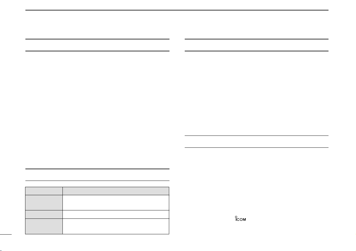
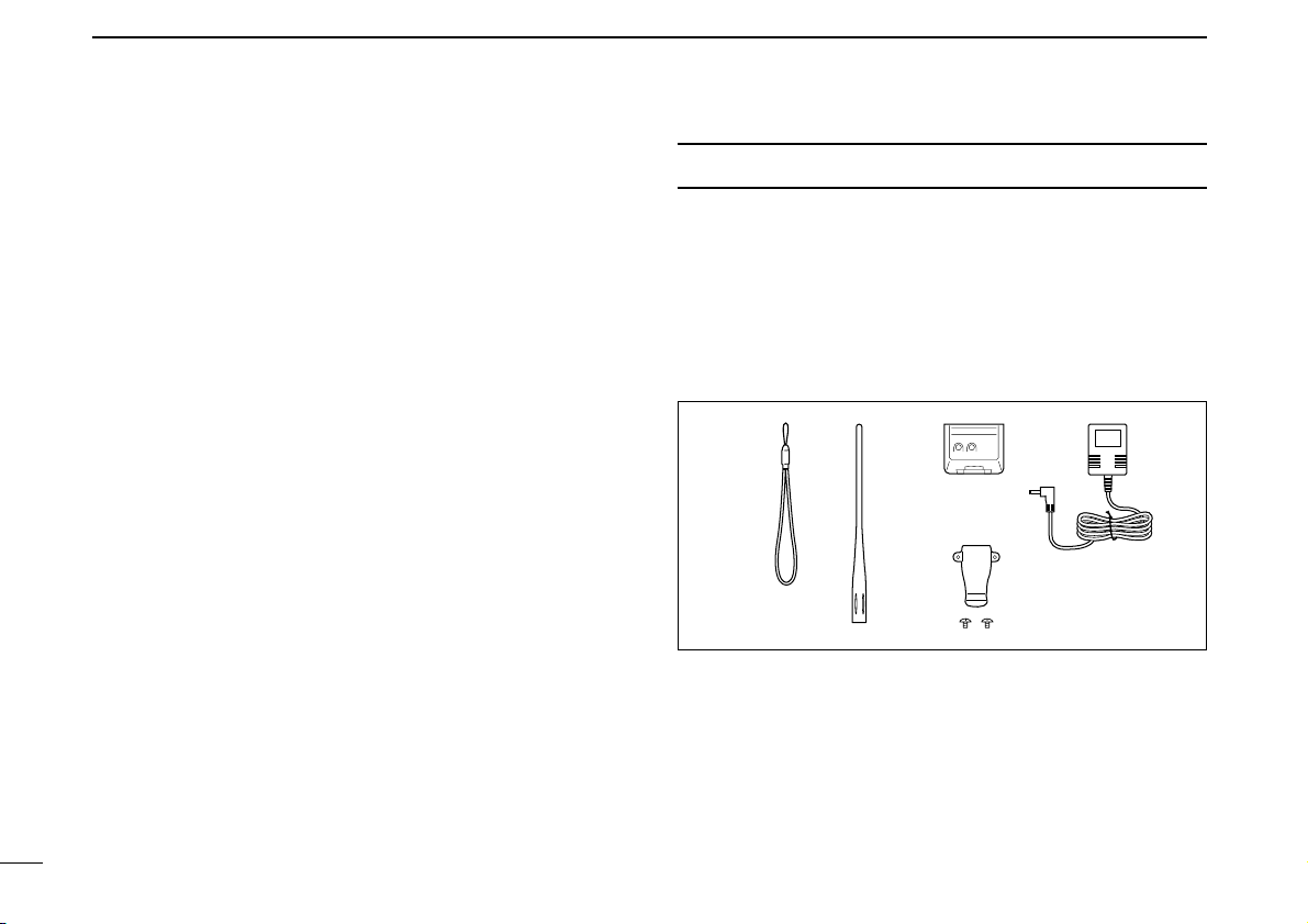
SUPPLIED ACCESSORIES
The following accessories are supplied with the transceiver.
q Hand strap ………………………………………………… 1
w Antenna …………………………………………………… 1
e Battery pack* ……………………………………………… 1
r Battery charger* …………………………………………… 1
t Belt clip
(with screws) ………………………………… 1 set
*Not supplied with some versions.
re
q
t
w
v
Page 7
1
1
ACCESSORY ATTACHMENT
1
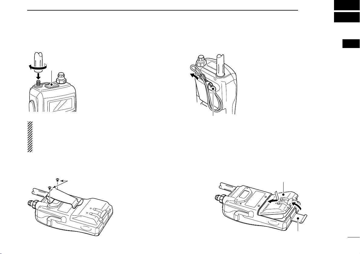
■ Antenna
Insert the supplied antenna into the
antenna connector and screw down
the antenna as shown at left.
NEVER carry the transceiver by holding the antenna.
KEEP the jack cover attached when
jack is not in use to protect the connector from dust and moisture.
✔
For your information
Third-party antennas may increase transceiver performance. An optional AD-92SMA
ANTENNA CONNECTOR
ADAPTER
is available to connect an antenna with a BNC
connector.
■ Belt clip
■ Handstrap
Slide the handstrap through the loop
on the top of the belt clip as illustrated
at left to facilitate carrying the
transceiver.
■ Battery pack
Attach the Li-Ion battery pack (BP-217) or battery case (BP-
216) as illustrated below.
• Charge the Li-Ion battery pack before use. (pgs. 10, 11)
Battery pack/
Battery case
Latch
q
w
Handstrap
Supplied screws*
*NOTE:
USE the supplied screws
only. Using screws longer than specified could
damage the transceiver.
Jack cover
Page 8
2
PANEL DESCRIPTION
2
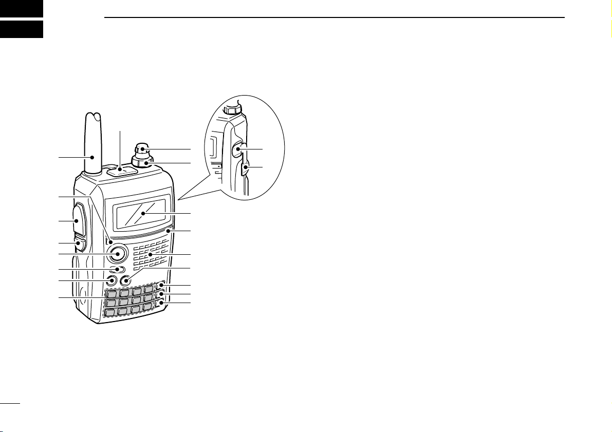
■ Front, top and side panels
qANTENNA CONNECTOR (p. 1)
Connects the supplied antenna.
• An optional AD-92SMA adapter (p. 122) is available for connecting an antenna with a BNC connector.
wTX/RX INDICATOR [TX/RX] (p. 24)
Lights green while receiving a signal or when the squelch
is open; lights red while transmitting.
ePTT SWITCH [PTT] (p. 24)
Push and hold to transmit, release to receive.
rSQUELCH KEY [SQL]
➥ Push and hold to open the squelch temporarily and
monitor the operating frequency. (p. 22)
➥ While pushing and holding this key, rotate [DIAL] to ad-
just the squelch level. (p. 21)
tMENU/LOCK KEY [MENU/LOCK]
➥ Push to toggle menu screen indication ON and OFF.
(p. 85)
➥ Push and hold for 1 sec. to toggle the lock function ON
and OFF. (p. 25)
yPOWER KEY [PWR]
Push and hold for 1 sec. to turn the transceiver power ON
and OFF.
uMAIN/DUAL KEY [MAIN/DUAL]
➥ Push to select the main band between A and B bands.
(p. 26)
➥ Push and hold for 1 sec. to toggle the dualwatch func-
tion ON and OFF. (p. 25)
iKEYPAD (pgs. 4, 5)
q
w
!5
Function display
Internal microphone
Speaker
!2
!6
e
r
t
y
u
i
!4
!3
o
!0
!1
!7
Page 9

3
2
PANEL DESCRIPTION
2
oCALL/RX➝CS KEY [CALL]/[RX➝CS](CALL)
➥ Push to select the call channel/TV channel/weather
channel. (p. 16)
➥ During DV mode operation, push and hold for 1 sec. to
set the received call signs (station and repeaters) for
operation. (p. 47)
➥ Enters or sends the DTMF code “C.” (pgs. 103, 104)
!0MEMORY/SELECT MEMORY WRITE KEY
[MR]/[S.MW](MR)
➥ Push to select memory mode. (p. 15)
➥ During memory mode operation, push to toggle be-
tween memory and memory bank mode. (p. 68)
➥ Push and hold for 1 sec. to enter select memory write
mode. (p. 64)
➥ Enters or sends the DTMF code “B.” (pgs. 103, 104)
!1VFO/MHz KEY [VFO]/[MHz](VFO)
➥ Push to toggle select VFO mode. (p. 15)
➥ During VFO mode operation, push and hold for 1 sec. to
select and toggle 1 MHz and 10 MHz tuning steps
(p. 18)
➥ Enters or sends the DTMF code “A.” (pgs. 103, 104)
!2BAND KEY [BAND]
➥ During VFO mode operation, push to select an operat-
ing frequency band. (pgs. 16, 17)
➥ During memory bank mode, push to select a memory
bank. (p. 68)
➥ Enters or sends the DTMF code “D.” (pgs. 103, 104)
!3EXTERNAL DC IN JACK [DC IN]
➥ Connects the supplied wall charger, BC-167, to charge
the attached battery pack. (p. 10)
➥ Connect an external DC power supply through the op-
tional CP-12L, CP-19R or OPC-254L for external DC
operation. (p. 13)
!4DATA JACK [DATA]
Connects a PC through the optional data communication
cable, OPC-1529R, for low-speed data communication or
control the transceiver remotely using the optional RS-91
(OPC-1529R is supplied). (p. 56)
!5VOLUME CONTROL [VOL]
Rotate to adjust the audio output level. (p. 20)
!6CONTROL DIAL [DIAL]
➥ Rotate to tune the operating frequency. (p. 18)
➥ During memory mode, rotate to select the memory
channel. (pgs. 15, 64)
➥ While pushing and holding [BAND], selects the operat-
ing band in VFO mode. (p. 18)
➥ While scanning, changes the scanning direction. (p. 75)
➥ While pushing and holding [SQL], sets the squelch
level. (p. 21)
➥ While pushing and holding [BAND], selects the pro-
grammed bank in memory mode. (p. 68)
!7EXTERNAL SPEAKER/MICROPHONE JACK [MIC/SP]
Connect an optional speaker-microphone or headset, if desired.
See page 122 for a list of available options.
Page 10

4
2 PANEL DESCRIPTION
DD
KEYPAD
KEY Pushed momentarily Pushed and held for 1 sec.
• Inputs digit ‘1’ for frequency input, memory channel selection,
etc.
• While pushing [PTT], this key sends the DTMF code “1.”
• Inputs digit ‘2’ for frequency input, memory channel selection,
etc.
• While pushing [PTT], this key sends the DTMF code “2.”
• Inputs digit ‘3’ for frequency input, memory channel selection,
etc.
• While pushing [PTT], this key sends the DTMF code “3.”
• Inputs digit ‘4’ for frequency input, memory channel selection,
etc.
• While pushing [PTT], this key sends the DTMF code “4.”
• Inputs digit ‘5’ for frequency input, memory channel selection,
etc.
• While pushing [PTT], this key sends the DTMF code “5.”
• Inputs digit ‘6’ for frequency input, memory channel selection,
etc.
• While pushing [PTT], this key sends the DTMF code “6.”
• Displays the simple band scope for a single sweep. (p. 23)
• Starts a scan. (p. 75)
• Toggles the transmit output power between high and low. (p. 24)
- “LOW” appears when low power is selected.
- While pushing and holding this key, with [DIAL] rotation selects
the output power.
• Activates the following duplex functions in order.
- Minus duplex operation— “–DUP” appears.
- Plus duplex operation— “+DUP” appears.
- Simplex operation— no duplex indicator appears.
- While pushing and holding this key, with [DIAL] rotation selects
the duplex function.
• Turn the frequency skip function ON and OFF in VFO mode, or
set the memory channel as the following skip channel in memory
mode in order (p. 79).
- Skip channel— “SKIP” appears.
- Frequency skip channel— “PSKIP” appears.
- Non-skip channel— no skip indicator appears.
• Turn the memory name or bank name indication ON and OFF.
(p. 70)
Page 11

5
2
PANEL DESCRIPTION
2
KEY Pushed momentarily Pushed and held for 1 sec.
• Inputs digit ‘7’ for frequency input, memory channel selection,
etc.
• While pushing [PTT], this key sends the DTMF code “7.”
• Inputs digit ‘8’ for frequency input, memory channel selection,
etc.
• While pushing [PTT], this key sends the DTMF code “8.”
• Inputs digit ‘9’ for frequency input, memory channel selection,
etc.
• While pushing [PTT], this key sends the DTMF code “9.”
• Inputs digit ‘0’ for frequency input, memory channel selection,
etc.
• While pushing [PTT], this key sends the DTMF code “0.”
• Inputs MHz digit for frequency input.
• While pushing [PTT], this key sends the DTMF code “F (#).”
• During DV mode operation, selects the record track for voice
memory. (p. 62)
• While pushing [PTT], this key sends the DTMF code “E (✱).”
• During FM/FM-N mode operation, selects repeater tone, tone
squelch, DTCS squelch and no tone operation in sequence.
(p. 110)
• During DV mode operation, selects digital call sign, digital code
and no tone operation in sequence. (p. 110)
• Selects tuning step selection. (p. 18)
• During FM/FM-N mode operation, starts tone scan function.
(p. 112)
• During DV mode operation, selects break-in operation mode.
(p. 51)
• During DV mode operation, set “CQCQCQ” for station’s call sign
for operation.
• Select DTMF memory mode. (p. 103)
• During DV mode operation, to turn EMR mode operation ON,
keep pushing and holding until 3 short and 1 long beeps are
emitted. (p. 56)
• Selects the operating mode.
Page 12
6
2 PANEL DESCRIPTION
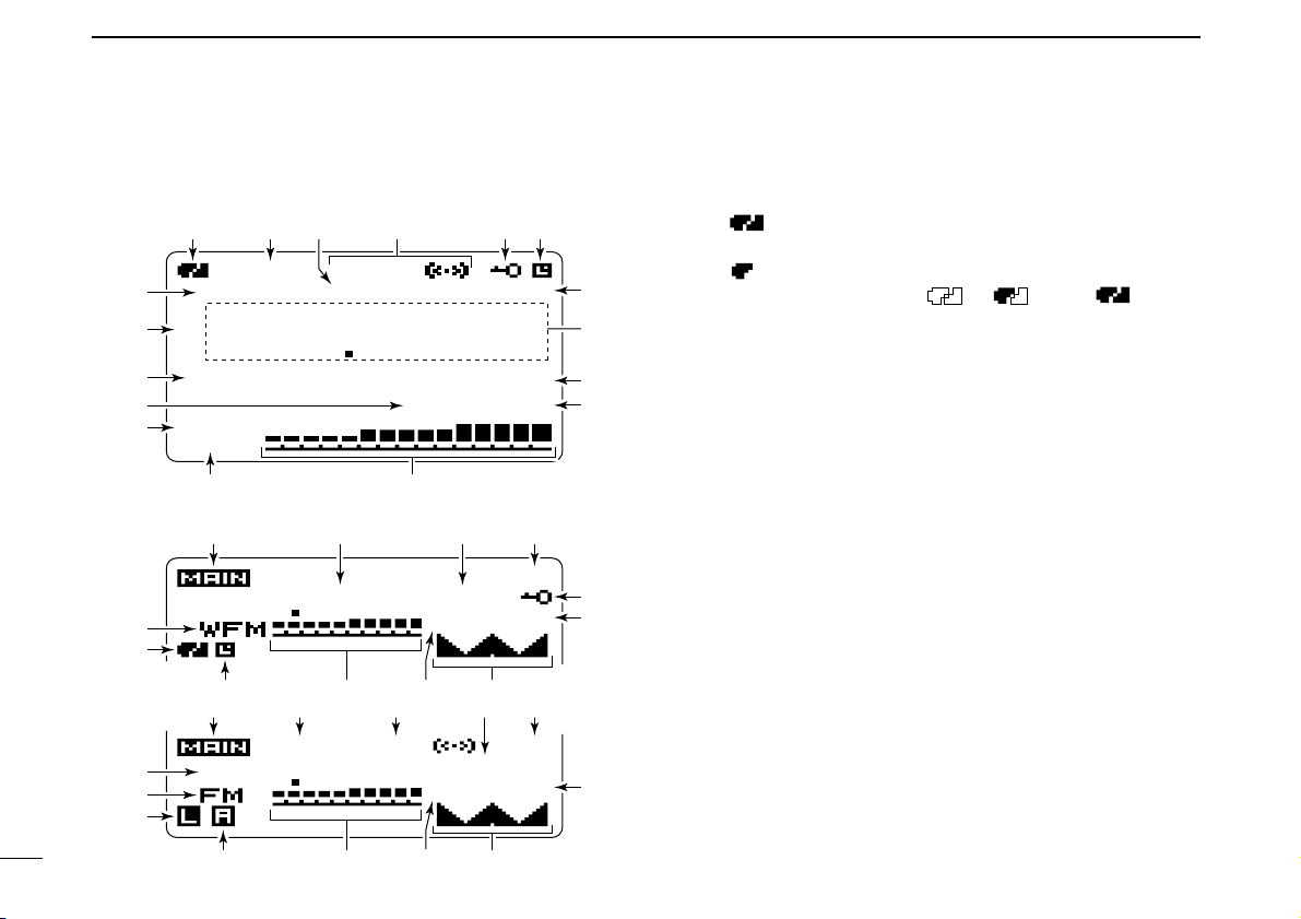
■ Function display
qBATTERY INDICATOR (pgs. 10, 12)
➥ “ ” (battery indicators) appear when the Li-Ion bat-
tery pack is attached.
➥ “ ” appears when the battery pack must be charged.
➥ The indicators show “ ,” “ ” and “ ” in se-
quence while charging the attached battery pack.
wDUPLEX INDICATORS (p. 29)
“+DUP” appears when plus duplex, “–DUP” appears when
minus duplex is selected.
ePRIORITY WATCH INDICATOR (p. 83)
Appears when priority watch is in use.
rTONE INDICATORS
• While operating in FM mode;
➥ “TONE” appears while the subaudible tone encoder is
in use. (pgs. 29, 106)
➥ “TSQL” appears while the tone squelch function is in
use. (p. 110)
➥ “DTCS” appears while the DTCS squelch function is in
use. (p. 110)
➥ “S” appears with the “TSQL” or “DTCS” indicator
while the pocket beep function
(with CTCSS or DTCS) is
in use. (p. 111)
• While operating in DV mode;
➥ “DSQL” appears while the call sign squelch function is
in use. (p. 110)
➥ “CSQL” appears while the digital code squelch function
is in use. (p. 110)
MemoName
µ
PRIO EMR
DSQL
DV
B
LOW
ATT
439 706
PSKIP
-DUP
25
000
PS
PRIOPRIO
25
µ
000000
88 100
DTCS
PS
PRIOPRIO
-DUP
75
µ
000000
439 706
q
!6 i e o
we r ty
!1
!8!1y !4
!2
!3
!7
q
!4
!5
!6
!7
u
t
!0
!6 w r e o
!8!1!2 !4
!7
i
!3
!0
i
o
!0
• Dualwatch indication
• Single band indication
Page 13

7
2
PANEL DESCRIPTION
2
➥ “S” appears with the “DSQL” or “CSQL” indicator
while the pocket beep function
(with digital call sign or dig-
ital code squelch) is in use. (p. 111)
tKEY LOCK INDICATOR (pgs. 25, 113)
Appears when the key lock function is activated.
yAUTO POWER OFF INDICATOR (p. 88)
Appears when the auto power OFF function is in use.
uEMR MODE INDICATOR (p. 56)
Appears when the EMR mode operation is selected.
iFREQUENCY READOUT
Displays a variety of information, such as operating frequency, set mode contents, memory names.
• The decimal point blinks during scan.
oSKIP INDICATORS (pgs. 79, 80)
➥ “SKIP” appears when the selected memory channel is
set as a skip channel.
➥ “P SKIP” appears when the displayed frequency is set
as a skip frequency.
!0MEMORY CHANNEL NUMBER INDICATOR
➥ Shows the selected memory channel number. (pgs. 64,
65)
➥ “C” appears when the call channel is selected. (pgs. 16,
65)
➥ “WX” appears when the weather channel is selected.
(pgs. 16, 114)
➥ “TV” appears when the TV channel is selected.
(pgs. 16, 28)
!1S/RF METER
➥ Shows the relative signal strength while receiving sig-
nals.
➥ Shows the output power level while transmitting. (p. 24)
!2ATTENUATOR INDICATOR (p. 22)
Appears when the RF attenuator is in use.
!3LOW POWER INDICATOR (p. 24)
➥ “LOW” appears when low power is selected.
➥ No indicator appears when high power is selected.
!4MEMORY INDICATOR (p. 64)
Appears when memory mode is selected.
!5NAME INDICATOR (p. 70)
During memory mode operation, the programmed memory
or memory bank name is displayed.
!6MAIN BAND INDICATOR (p. 14)
Shows which operating band, “A” or “B,” is selected for the
main band.
!7OPERATING MODE INDICATOR (p. 21)
Shows the selected operating mode.
• DV, FM, FM-N, WFM and AM are available, depending on operating band.
!8SIMPLE BAND SCOPE INDICATOR (p. 23)
When the simple band scope function is in use, shows the
band conditions.
Page 14

8
BATTERY CHARGING
3
■ Caution
• R DANGER! Use and charge only specified Icom battery
packs with Icom radios. Only Icom battery packs are tested
and approved for use with Icom radios. Using third-party or
counterfeit battery packs may cause smoke, fire, or cause
the battery to burst.
DD
Battery caution
• R DANGER! DO NOT hammer or otherwise impact the bat-
tery. Do not use the battery if it has been severely impacted
or dropped, or if the battery has been subjected to heavy
pressure. Battery damage may not be visible on the outside
of the case. Even if the surface of the battery does not show
cracks or any other damage, the cells inside the battery may
rupture or catch fire.
• R DANGER! NEVER use or leave battery pack in areas
with temperatures above +60˚C (+140˚F). High temperature
buildup in the battery, such as could occur near fires or
stoves, inside a sun heated car, or in direct sunlight may
cause the battery to rupture or catch fire. Excessive temperatures may also degrade battery performance or shorten
battery life.
• R DANGER! DO NOT expose the battery to rain, snow,
seawater, or any other liquids. Do not charge or use a wet
battery. If the battery gets wet, be sure to wipe it dry before
using. The battery is not waterproof.
• R DANGER! NEVER incinerate an used battery pack since
internal battery gas may cause it to rupture, or may cause
an explosion.
• R DANGER! NEVER solder the battery terminals, or
NEVER modify the battery pack. This may cause heat generation, and the battery may burst, emit smoke or catch fire.
• R DANGER! Use the battery only with the transceiver for
which it is specified. Never use a battery with any other
equipment, or for any purpose that is not specified in this instruction manual.
• R DANGER! If fluid from inside the battery gets in your
eyes, blindness can result. Rinse your eyes with clean
water, without rubbing them, and see a doctor immediately.
• WARNING! Immediately stop using the battery if it emits an
abnormal odor, heats up, or is discolored or deformed. If any
of these conditions occur, contact your Icom dealer or distributor.
• WARNING! Immediately wash, using clean water, any part
of the body that comes into contact with fluid from inside the
battery.
Misuse of Lithium-Ion batteries may result in the following hazards: smoke, fire, or the battery may rupture.
Misuse can also cause damage to the battery or degradation of battery performance.
Page 15

9
3
BATTERY CHARGING
3
• WARNING! NEVER put the battery in a microwave oven,
high-pressure container, or in an induction heating cooker.
This could cause a fire, overheating, or cause the battery to
rupture.
• CAUTION! Always use the battery within the specified tem-
perature range, –20˚C to +60˚C (–4˚F to +140˚F). Using the
battery out of its specified temperature range will reduce the
battery’s performance and battery life.
• CAUTION! Shorter battery life could occur if the battery is
left fully charged, completely discharged, or in an excessive
temperature environment (above +50˚C; +122˚F) for an extended period of time. If the battery must be left unused for a
long time, it must be detached from the radio after discharging. You may use the battery until the battery indicator
shows half-capacity, then keep it safely in a cool dry place
with the temperature between –20˚C to +20˚C (–4˚F to
+68˚F).
DD
Charging caution
• R DANGER! NEVER charge the battery pack in areas with
extremely high temperatures, such as near fires or stoves,
inside a sun heated car, or in direct sunlight. In such environments, the safety/protection circuit in the battery will activate, causing the battery to stop charging.
• WARNING! DO NOT charge or leave the battery in the bat-
tery charger beyond the specified time for charging. If the
battery is not completely charged by the specified time, stop
charging and remove the battery from the battery charger.
Continuing to charge the battery beyond the specified time
limit may cause a fire, overheating, or the battery may rupture.
• WARNING! NEVER insert the transceiver (battery attached
to the transceiver) into the charger if it is wet or soiled. This
could corrode the battery charger terminals or damage the
charger. The charger is not waterproof.
• CAUTION! DO NOT charge the battery outside of the spec-
ified temperature range: 0˚C to +35˚C (+32˚F to +95˚F).
Icom recommends charging the battery at +20˚C (+68˚F).
The battery may heat up or rupture if charged out of the
specified temperature range. Additionally, battery performance or battery life may be reduced.
Page 16
10
3 BATTERY CHARGING
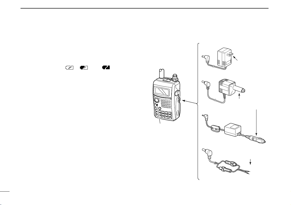
■ Regular charging
Prior to using the transceiver for the first time, the battery
pack must be fully charged for optimum life and operation.
DD
Battery indicators
The indicators show “ ,” “ ” and “ ” in sequence
while charging, and both indicators disappear when completely charged.
DD
Charging note
• Be sure to turn the transceiver power OFF.
Otherwise the battery pack will not be charged completely or takes
longer charging time periods.
• External DC power operation becomes possible when using
an optional CP-12L, CP-19R or OPC-254L. The attached
battery pack is also charged simultaneously, except during
transmit. (see p. 11 for more details)
• The external DC power supply voltage must be within
10–16 V to charge the battery pack and operation when
using an optional OPC-254L.
• BC-167A/D
• CP-12L (Optional)
• CP-19R (Optional)
• OPC-254L (Optional)
to AC outlet
to cigarette lighter
socket (12 V DC)
to 12 V DC
(power supply)
White: +
Black: _
Transceiver
to
[DC IN]
Turn power OFF while
charging the battery
pack.
• Charging time period:
Approx. 6 hours
Page 17
11
3
BATTERY CHARGING
3
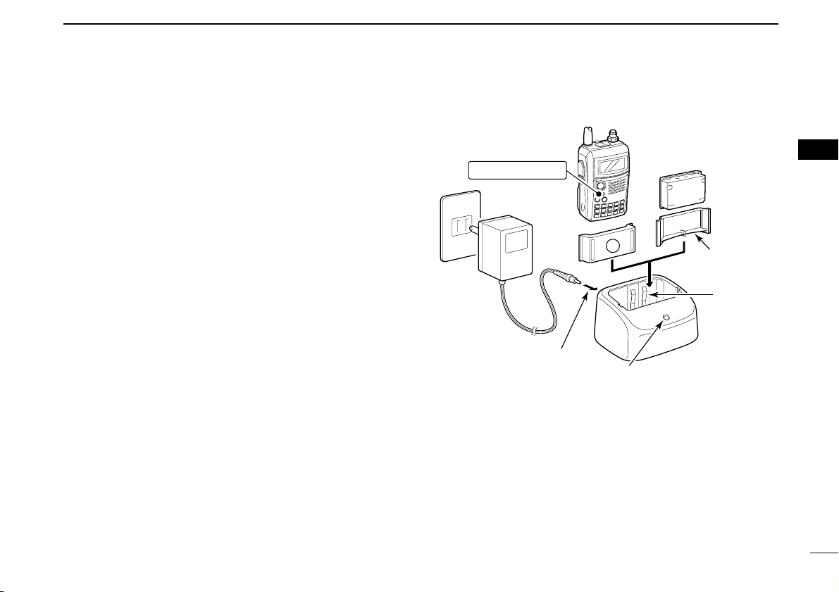
■ Rapid charging
The optional BC-139 provides rapid charging of the battery
pack.
• Charging period: 2.5 hours (with BP-217)
DD
Charging note
• Be sure to turn the transceiver power OFF.
Detach the battery pack from the transceiver then charge
the battery pack by itself, or charge the battery with regular
charging when the transceiver power cannot be turned OFF.
Otherwise the battery pack will not be charged
(charging indi-
cator on the BC-139 blinks orange).
• The desktop charger, BC-139, can only be charged BP-217.
Other types of rechargeable battery, Ni-Cd or Ni-MH, cannot be charged.
• If the charging indicator blinks orange, there may be a problem with the battery pack
(or charger). Reinsert the battery
pack or contact your dealer.
• The optional CP-12L, CP-19R and OPC-254L can be used
instead of the supplied AC adapter
(BC-123). Connect one of
these to the [AC ADAPTER] jack in this case.
A
Transceiver
(with battery pack)
Turn power OFF.
Check the
orientation.
Battery pack
to AC outlet
BC-139 (optional)
Desktop charger
to [AC ADAPTER]
Adapter (supplied
with BC-139)
Charging indicator
Charging : Orange
Finished : Green
Charging
terminal
BC-123
(supplied
with BC-139)
Page 18
12
3 BATTERY CHARGING
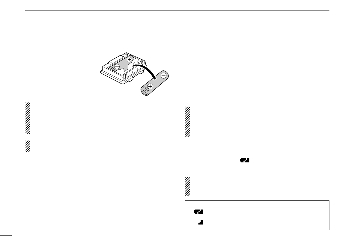
■ Optional battery case
➥ Install 2 R6 (AA) size alka-
line batteries into the optional BP-216
BATTERY
CASE
.
• Be sure to observe the correct polarity.
A built-in step-up convertor in the BP-216 increases the
voltage to 5 V DC.
Approx. 100 mW of output power is possible with the BP-
216 operation. Also, no transmit output power selection is
available.
Keep battery contacts clean. It’s a good idea to clean battery terminals once a week.
D Battery information
The batteries may seem to have low capacity when used in
low temperatures such as –10°C
(+14°F) or below. Keep the
battery case or pack warm in this case.
D Battery replacement
When the batteries become exhausted, the function display
may blink or have a lower contrast. In these cases, replace
all batteries with new, same brand, alkaline batteries.
■ Battery information
DD
Battery life
The transceiver operates with the BP-217 as follows.
However, when operating in DV mode, operating time may be
shortened by one-half hour.
• VHF band : Approx. 5 hours
• UHF band : Approx. 4.5 hours
(Tx: Rx: Stand-by=1: 1: 8)
Even when the transceiver power is OFF, a slight current
still flows in the circuits. Remove the battery pack or case
from the transceiver when not using it for a long time. Otherwise, the battery pack or installed batteries will become
exhausted.
DD
Battery indicator
The battery indicator, “ ,” appears only when the BP-217
is attached to the transceiver.
The battery indicator does not appear when turning power
ON after the charging is completed without disconnecting
the battery charger or external DC power.
Indication Battery condition
The battery has ample capacity.
The battery is nearing exhaustion. Charging is necessary.
Page 19
13
3
BATTERY CHARGING
3
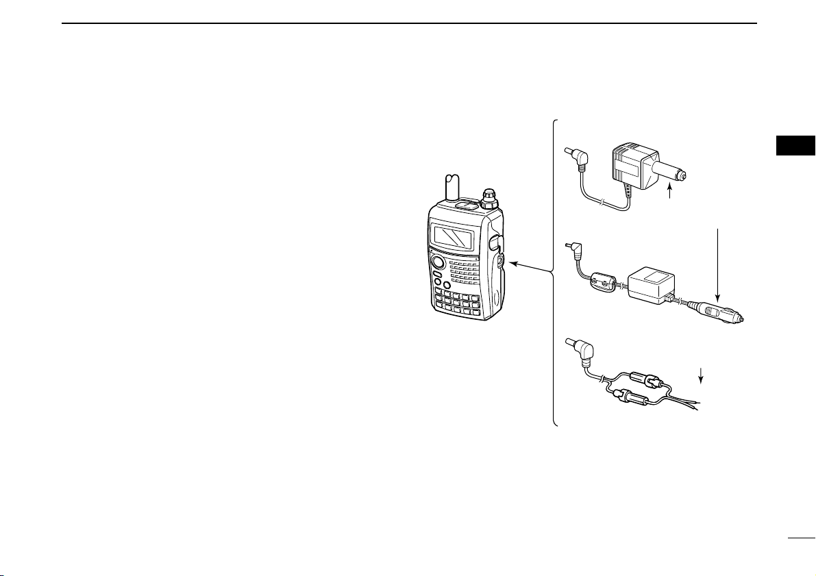
■ External DC power operation
An optional cigarette lighter cable (CP-12L or CP-19R; for 12 V
cigarette lighter socket) or external DC power cable (OPC-254L)
can be used for external power operation.
DD
Operating note
• Power supply range is between 10.0–16.0 V DC.
NEVER CONNECT OVER 16 V DC directly into the [DC IN]
jack of the transceiver.
• BE SURE to use CP-12L,CP-19R or OPC-254L when connecting a regulated 12 V DC power supply.
Use an external DC-DC converter to connect the transceiver
through optional CP-12L, CP-19R or OPC-254L to a 24 V
DC power source.
• The voltage of the external power supply must be within
10–16 V DC when using either CP-12L, CP-19R or OPC254L, otherwise, use the battery pack.
• Up to 5 W
(approx.) of maximum output power is provided
with the external DC power operation, however, when the
supplied voltage exceeds 14 V, the built-in protection circuit
activates to reduce the transmit output power to 0.5 W
(ap-
prox.).
• Disconnect the power cables from the transceiver when not
using it. Otherwise, the vehicle battery will become exhausted.
• The power save function is deactivated automatically during
external DC power operation.
• CP-12L (Optional)
• CP-19R (Optional)
• OPC-254L (Optional)
to cigarette lighter
socket (12 V DC)
to 12 V DC
(power supply)
White: +
Black: _
Transceiver
to
[DC IN]
Page 20
14
FREQUENCY AND CHANNEL SETTING
4
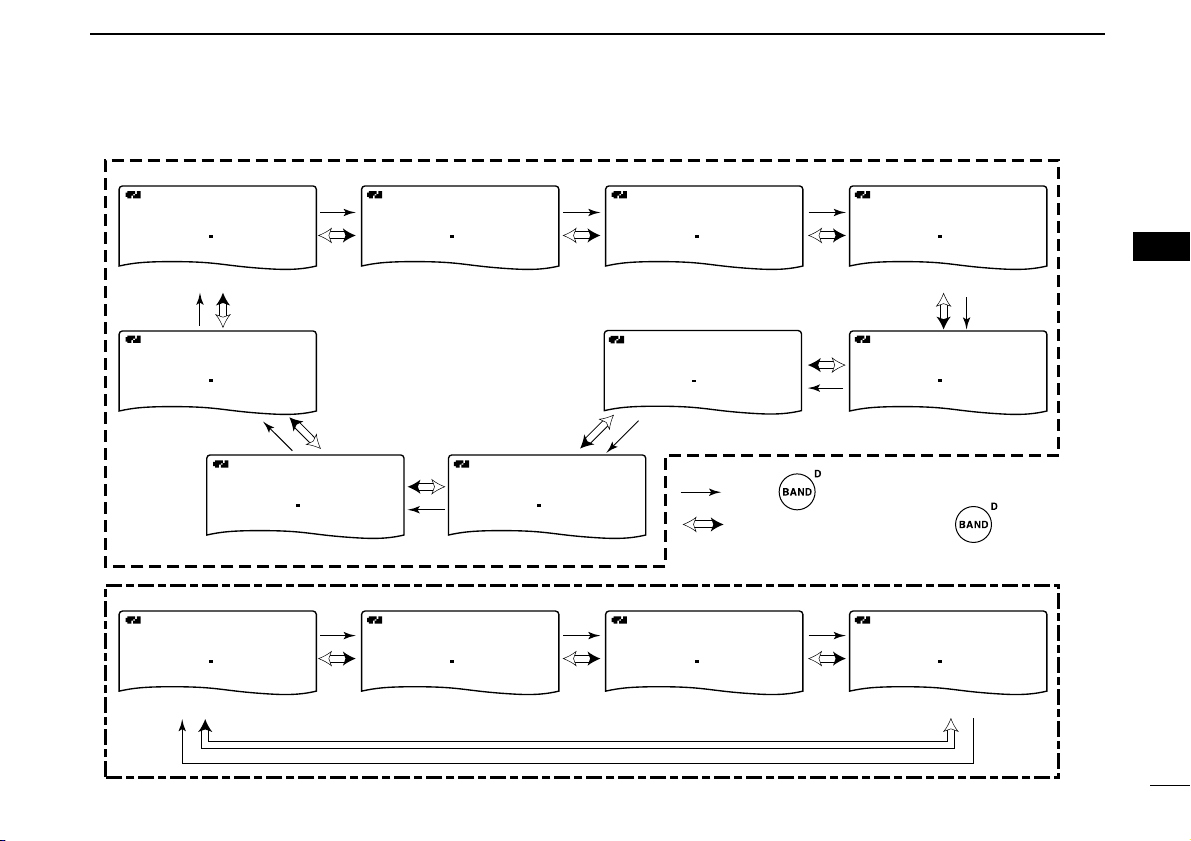
■ Main band selection
The IC-91A/91AD has two independent operating bands; A
band
(VFO A) and B band (VFO B). A band
(VFO A) can operate
0.495 MHz to 999.990 MHz*, and B band
(VFO B) can operate
118 MHz to 174 MHz and 350 MHz to 470 MHz.
*Some frequency ranges are blocked for the USA version by regula-
tion.
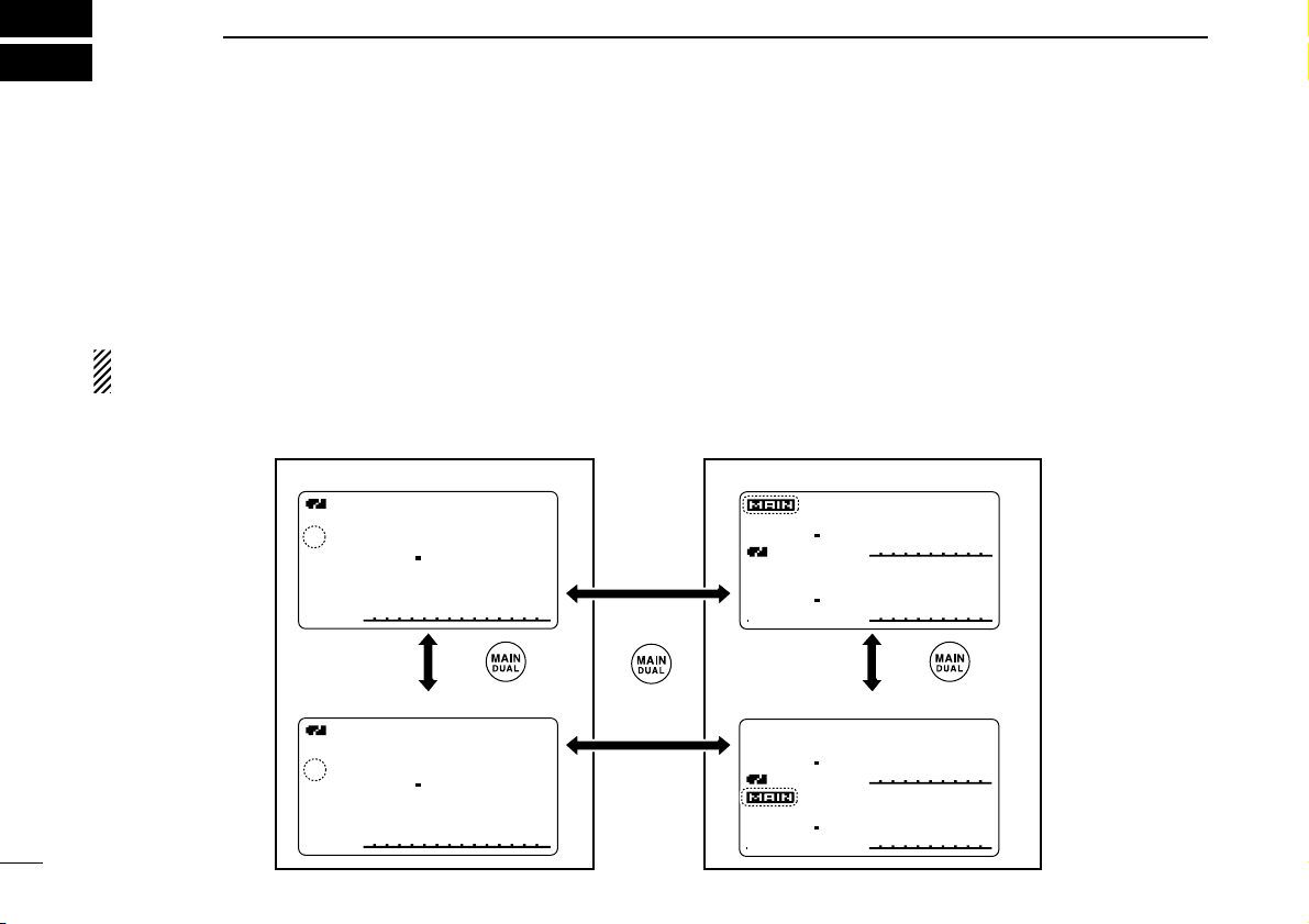
NOTE: When in dualwatch mode, transmission is available
from the MAIN band only.
DD
How to change the main band
➥ Push [MAIN/DUAL] to toggle between A and B band.
➥ Push and hold [MAIN/DUAL] for 1 sec. to turn the dual-
watch operation ON and OFF.
• While in dualwatch operation, the display indicates A band in the
upper half and B band in the lower half.
➥ During dualwatch operation, push [MAIN/DUAL] to select
A band or B band as the main operating band alternately.
DTCS
DTCS
W
PS
EM
W
PS
FMFM
PRIO
PRIO
+DUP+DUP
+DUP+DUP
FM
146 010
440 000
25
50
µ
000000
µ
000000
DTCS
DTCS
W
PS
EMEM
W
PS
FMFM
PRIO
PRIO
+DUP+DUP
+DUP+DUP
FM
146 010
440 000
25
50
µ
000000
µ
000000
A
MemoName
µ
PRIOPRIO WXWX EMREMR
DTCSDTCS
FMFM
LOWLOW
ATTATT
146 010
P SKIPSKIP
+DUP+DUP
2525
000
MemoName
µ
PRIOPRIO WXWX EMREMR
DTCSDTCS
FMFM
B
LOWLOW
ATTATT
440 000
P SKIPSKIP
+DUP+DUP
2525
000
Push Push
• Selecting A band • Selecting upper side as main band
• Selecting lower side as main band
• Selecting B band
Push
Single band operation Dualwatch operation
for 1 sec.
Page 21
15
4
FREQUENCY AND CHANNEL SETTING
4
■ Mode selection
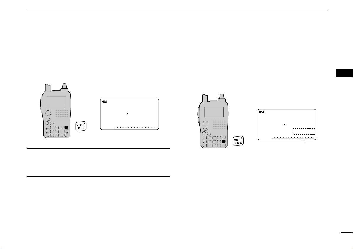
DD
VFO mode
VFO mode is used to set the desired frequency.
➥ Push [VFO] to select VFO mode.
What is VFO?
VFO is an abbreviation of Variable Frequency Oscillator. Frequencies for both transmitting and receiving are generated
and controlled by the VFO.
DD
Memory mode
Memory mode is used for operation on memory channels
which store programmed frequencies.
qPush [MR] to select memory mode.
•“µµ” appears when memory mode is selected.
wRotate [DIAL] to select the desired memory channel.
• Only programmed memory channels can be selected.
• Enter the memory channel directly to select the desired memory
channel. (p. 64)
• See p. 66 for memory programming details.
A
MemoName
µ
PRIOPRIO WXWX EMREMR
DTCSDTCS
FMFM
LOWLOW
ATTATT
146 010
P SKIP
+DUP+DUP
25
000000
• Memory mode indication
Appear
A
MemoNameMemoName
µ
PRIOPRIO WXWX EMREMR
DTCSDTCS
FMFM
LOWLOW
ATTATT
146 010
P SKIP
+DUP+DUP
25
000000
• VFO mode indication
Page 22
16
4 FREQUENCY AND CHANNEL SETTING
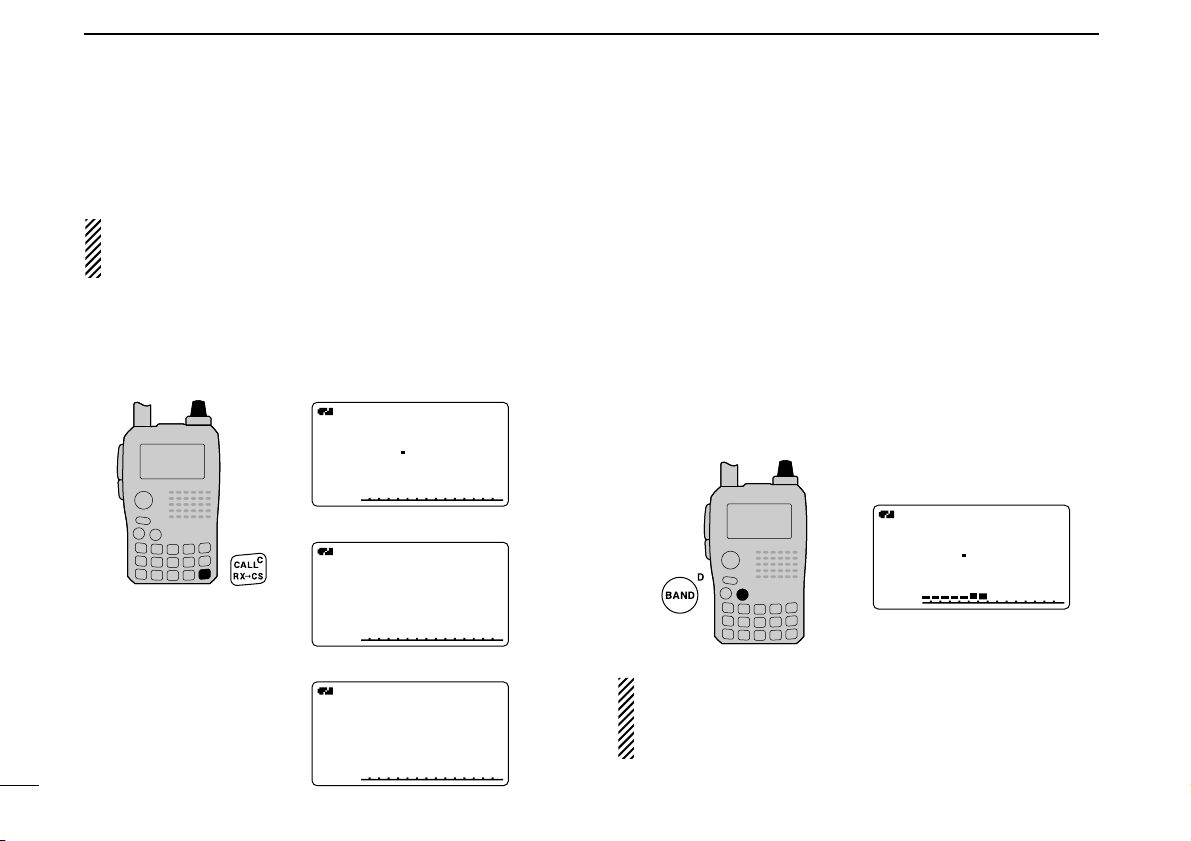
DD
Call/TV*/Weather
†
channels
Call channels are used for quick recall of most-often used frequencies.
*Appears only when TV channels are programmed via the
optional RS-91. Also available for A band operation only.
†
Available for the USA version only.
qPush [CALL] several times to select call channels/TV
channels (A band only)/Weather channels.
• Call/TV/Weather channels can be selected in sequence.
wRotate [DIAL] to select the desired channel.
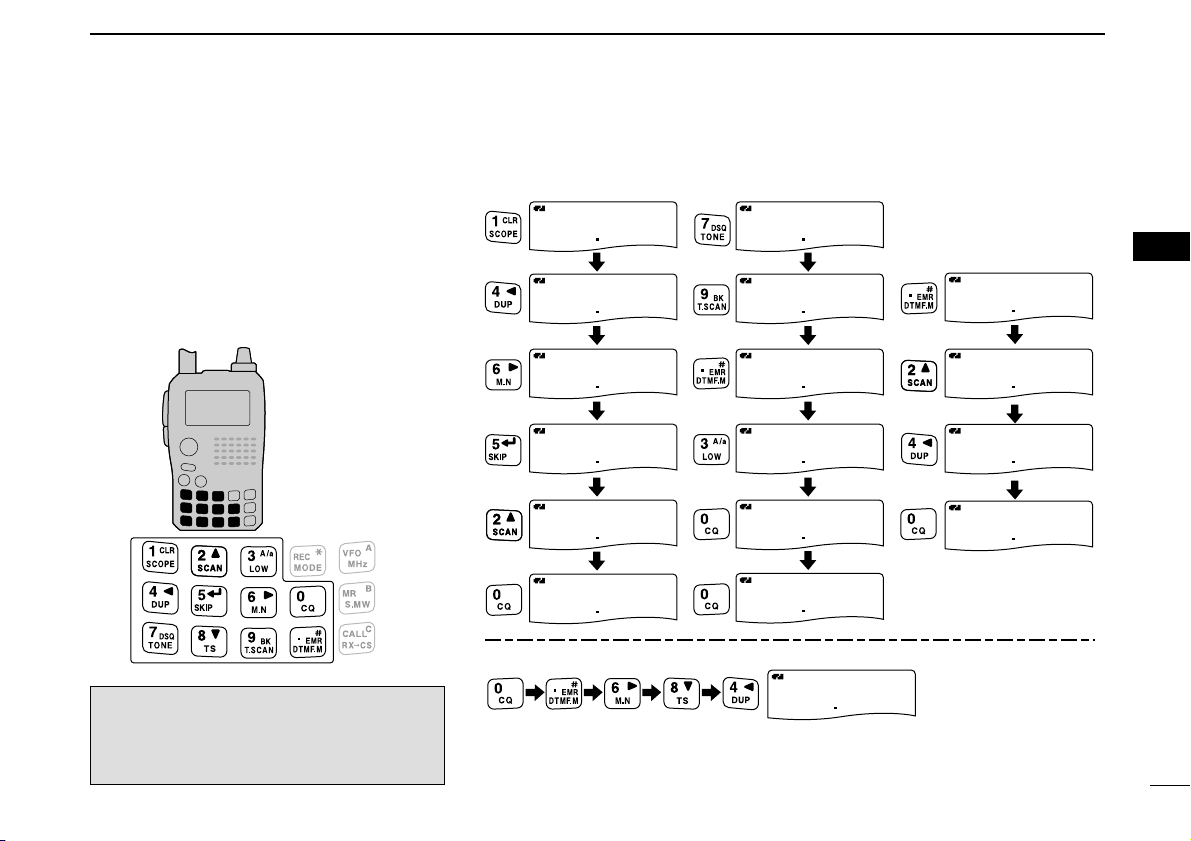
■ Operating band selection
The transceiver can receive the AM broadcast, HF bands,
50 MHz, FM broadcast, VHF air, 144 MHz, 300 MHz,
400 MHz or 800 MHz* bands.
(Some bands are not selectable
for B band operation. See next page for details.)
➥ In VFO mode, push [BAND] several times to select the de-
sired frequency band.
• If the other than VFO mode is selected, such as a memory channel/call channel/TV channel/Weather channel, push [VFO] to se-
lect VFO mode first, then push [BAND] to select the desired
band.
➥ While pushing and holding [BAND], rotating [DIAL] also
selects frequency band.
Available frequency bands are different depending on version. See the specification for details. (pgs. 120, 121)
*Some frequency ranges are blocked for the USA version
by regulation.
A
MemoName
µ
PRIOPRIO WXWX EMREMR
DTCSDTCS
FMFM
LOWLOW
ATTATT
146 010
P SKIP
+DUP+DUP
25
000000
[DIAL]
[DIAL]
A
MemoNameMemoName
µ
PRIOPRIO WXWX EMREMR
DTCSDTCS
FMFM
LOWLOW
ATTATT
146 010
P SKIP
+DUP+DUP
25
C0C0
TVTV
A
MemoNameMemoName
µ
PRIOPRIO WXWX EMREMR
DTCSDTCS
WFMWFM
LOWLOW
ATTATT
10 ch
P SKIP
+DUP+DUP
25
WXWX
A
MemoNameMemoName
µ
PRIOPRIO WXWX EMREMR
DTCSDTCS
WFMWFM
LOWLOW
ATTATT
1
P SKIP
+DUP+DUP
25
• Call channel indication
• TV channel indication
• Weather channel indication
Page 23
17
4
FREQUENCY AND CHANNEL SETTING
1
2
3
4
5
6
7
8
9
10
11
12
13
14
15
16
17
18
19
• Available frequency bands
A
MemoName
PRIOPRIO WXWX EMREMR
DTCSDTCS
AMAM
118 000
P SKIP
+DUP+DUP
25
A
MemoNameMemoName
PRIOPRIO WXWX EMREMR
DTCSDTCS
AMAM
B
118 000
P SKIP
+DUP+DUP
25
A
MemoName
PRIOPRIO WXWX EMREMR
DTCSDTCS
FMFM
B
146 010
P SKIP
+DUP+DUP
25
A
MemoNameMemoName
PRIOPRIO WXWX EMREMR
DTCSDTCS
FMFM
B
370 000
P SKIP
+DUP+DUP
25
A
MemoName
PRIOPRIO WXWX EMREMR
DTCSDTCS
FMFM
B
440 000
P SKIP
+DUP+DUP
25
A
MemoNameMemoName
PRIOPRIO WXWX EMREMR
DTCSDTCS
FMFM
850 000
P SKIP
+DUP+DUP
25
A
MemoNameMemoName
PRIOPRIO WXWX EMREMR
DTCSDTCS
FMFM
440 000
P SKIP
+DUP+DUP
25
A
MemoNameMemoName
PRIOPRIO WXWX EMREMR
DTCSDTCS
AMAM
370 000
P SKIP
+DUP+DUP
25
A
MemoNameMemoName
PRIOPRIO WXWX EMREMR
DTCSDTCS
FMFM
146 010
P SKIP
+DUP+DUP
25
A
MemoNameMemoName
PRIOPRIO WXWX EMREMR
DTCSDTCS
AMAM
001 620
P SKIP
+DUP+DUP
25
A
MemoName
PRIOPRIO WXWX EMREMR
DTCSDTCS
AMAM
005 000
P SKIP
+DUP+DUP
25
A
MemoNameMemoName
PRIOPRIO WXWX EMREMR
DTCSDTCS
FMFM
051 000
P SKIP
+DUP+DUP
25
A
MemoName
PRIOPRIO WXWX EMREMR
DTCSDTCS
WFMWFM
076 000
P SKIP
+DUP+DUP
25
AM broadcast band HF band
• A band
• B band
50 MHz band
800 MHz band
400 MHz band
400 MHz band
FM broadcast band
VHF air band
VHF air band
144 MHz band
144 MHz band
300 MHz band
300 MHz band
: Push
: Rotating [DIAL] while pushing
Initial frequencies shown differ according to version.
Page 24
18
4 FREQUENCY AND CHANNEL SETTING
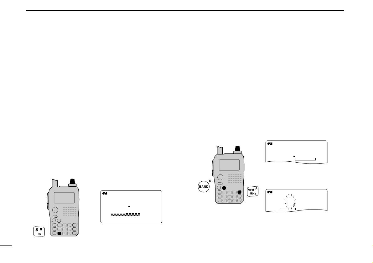
■ Setting a tuning step
The tuning step can be selected for each frequency band.
The following tuning steps are available for the IC-91A/91AD.
• 5.0 kHz* • 6.25 kHz* • 8.33 kHz
†
• 9.0 kHz‡• 10.0 kHz
• 12.5 kHz • 15.0 kHz • 20.0 kHz • 25.0 kHz • 30.0 kHz
• 50.0 kHz • 100.0 kHz • 125.0 kHz • 200.0 kHz
* Appears for below the 600 MHz bands only.
†
Appears for the VHF air band only.
‡
Appears for the AM broadcast band only.
DD
Tuning step selection
qPush [VFO] to select VFO mode, if necessary.
wPush [BAND] to select the desired frequency band.
• Or, while pushing and holding [BAND], rotate [DIAL] to select
the desired frequency band.
e
Push and hold [TS](8) for 1 sec. to enter tuning step set mode.
rRotate [DIAL] to select the desired tuning step.
tPush [TS](8) (or [VFO]) to return to VFO mode.
■ Setting a frequency
DD
Using the dial
qPush [VFO] to select VFO mode, if necessary.
wSelect the desired frequency band with [BAND].
• Or, while pushing and holding [BAND], rotate [DIAL] to select
the desired frequency band.
eRotate [DIAL] to select the desired frequency.
• The frequency changes according to the preset tuning steps.
See the left-hand side of the page to set the tuning step.
• Push and hold [MHz](VFO) for 1 sec. then rotate [DIAL] to
change the frequency in 1 MHz steps, or push and hold for 1 sec.
again then rotate [DIAL] to change the frequency in 10 MHz
steps. (Each pushing and holding for 1 sec. toggles 1 MHz or
10 MHz tuning steps. Push [MHz](VFO) to cancel it.)
A
PRIOPRIO WXWX EMREMR
DTCSDTCS
FMFM
146 010
+DUP+DUP
25
A
PRIOPRIO WXWX EMREMR
DTCSDTCS
FMFM
146 010
+DUP+DUP
25
[DIAL]
[DIAL] changes the frequency according to the selected tuning step.
After pushing and holding
[MHz](VFO) for 1 sec.,
[DIAL] changes the frequency in 1 MHz/10 MHz steps.
A
PRIOPRIO WXWX EMREMR
DTCSDTCS
FMFM
146 010
P
+DUP+DUP
25
SET-TS:5.0kHz
µ
000000
SKIP
[DIAL]
5 kHz tuning step
Page 25
19
4
FREQUENCY AND CHANNEL SETTING
1
2
3
4
5
6
7
8
9
10
11
12
13
14
15
16
17
18
19
DD
Using the keypad
The frequency can be directly set via numeric
keys.
• If a frequency outside the frequency range is entered, the previously displayed frequency is automatically recalled after editing last digit.
qPush [VFO] to select VFO mode, if neces-
sary.
w Enter the desired frequency via the keypad.
A
PRIO WX
DTCS
FM
730 000
+DUP
2525
A
PRIO WX
DTCS
FM
790 000
+DUP
2525
A
PRIO WX
DTCS
FM
079 300
+DUP
2525
A
PRIO WX
DTCS
FM
079 3 00
+DUP
2525
A
PRIO WX
DTCS
FM
079 300
+DUP
2525
A
PRIO WX
DTCS
FM
079 300
+DUP
2525
A
PRIO WX
DTCS
FM
146 520
+DUP
2525
A
PRIO WX
DTCS
FM
146 520
+DUP
2525
A
PRIO WX
DTCS
FM
146 520
+DUP
2525
A
PRIO WX
DTCS
FM
146 520
+DUP
2525
A
PRIO WX
DTCS
FM
146 520
+DUP
2525
A
PRIO WX
DTCS
FM
146 520
+DUP
2525
A
PRIO WX
DTCS
FM
146 240
+DUP
2525
A
PRIO WX
DTCS
FM
000 684
+DUP
2525
A
PRIO WX
DTCS
FM
146 240
+DUP
2525
A
PRIO WX
DTCS
FM
146 240
+DUP
2525
A
PRIO WX
DTCS
FM
146 240
+DUP
2525
• Entering 146.520 MHz• Entering
79.3 MHz
• Editting to 684 kHz
• Changing 100 kHz
and below.
Editting
146.520 MHz
to 146.240 MHz
Depending on the tuning step setting, the 1
kHz digit may not acceptable as input. In
this case, enter “0” as 1 kHz digit, then ro-
tate [DIAL] to set the desired frequency.
Page 26
20
BASIC OPERATION
5
■ Receiving
Make sure charged battery pack (BP-217) or brand new alkaline batteries (BP-216) are installed (pgs. 1, 12).
qPush and hold [PWR] for 1 sec. to turn power ON.
wRotate [VOL] to set the desired audio level.
• The frequency display shows the volume level while setting. See
the section at right for details.
eSet the receiving frequency. (p. 18)
rSet the squelch level. (p. 21)
• While pushing and holding [SQL], rotate [DIAL].
• The first click of [DIAL] indicates the current squelch level.
•“LEVEL 1” is loose squelch (for weak signals) and “LEVEL 9” is
tight squelch (for strong signals).
•“AUTO” indicates automatic level adjustment by a noise pulse
counting system.
• Push and hold [SQL] to open the squelch manually.
tWhen a signal is received:
• Squelch opens and audio is output.
• The S/RF-meter shows the relative signal strength level.
■ Setting audio volume
➥ Rotate [VOL]
to adjust the audio level.
• If squelch is closed, push and hold [SQL] to verify the audio
level.
• The display shows the volume level while setting.
µ
000000
VOLVOL
µ
000000
VOLVOL
µ
000000
VOLVOL
A
MemoName
µ
PRIOPRIO WXWX EMREMR
DTCSDTCS
FMFM
LOWLOW
ATTATT
146 010
P SKIP
P SKIP
P SKIP
P SKIP
+DUP+DUP
25
000000
Minimum setting
(no audio)
Volume level indicator
Maximum setting
[VOL]
q [PWR]
e Set frequency
r Set squelch level
w Set audio level
e Select band
r Push for setting
the squelch
(Push to monitor)
Page 27
21
5
BASIC OPERATION
1
2
3
4
5
6
7
8
9
10
11
12
13
14
15
16
17
18
19
■ Setting squelch level
The squelch circuit mutes the received audio signal depending on the signal strength. The receiver has 9 squelch levels,
a continuously open setting and an automatic squelch setting.
➥ While pushing and holding [SQL], rotate [DIAL] to select
the squelch level.
•“LEVEL 1” is loose squelch (for weak signals) and “LEVEL 9” is
tight squelch (for strong signals).
•“AUTO” indicates automatic level adjustment by a noise pulse
counting system.
•“OPEN” indicates continuously open setting.
■ Operating mode selection
Operating modes are determined by the modulation of the
radio signals. The transceiver has total 5 operating modes (A
band: FM, WFM and AM modes, B band FM, FM-N, AM and
DV modes). The mode selection is stored independently for
each band and memory channel.
Typically, AM mode is used for the AM broadcast stations
(0.495–1.620 MHz) and air band (118–136.995 MHz), and
WFM is used for FM broadcast stations (76–107.9 MHz).
WFM mode cannot be selected above 810 MHz for USA version.
➥ Push and hold [MODE](REC) for 1 sec. several times to
select the desired operating mode.
A
FMFM
146 010
25
A
WFMWFM
176 000
25
A
AMAM
118 000
25
FM mode
WFM mode
AM mode
• Display example
A
MemoNameMemoName
µ
PRIOPRIO WXWX EMREMR
DTCSDTCS
FMFM
LOWLOW
ATTATT
146 010
P SKIP
+DUP+DUP
25
000000
SQUELCH:LEVEL9
µ
000000
P SKIP
SQUELCH:AUTO
µ
000000
P SKIP
Automatic squelch
Maximum level
[DIAL]
Page 28
22
5 BASIC OPERATION
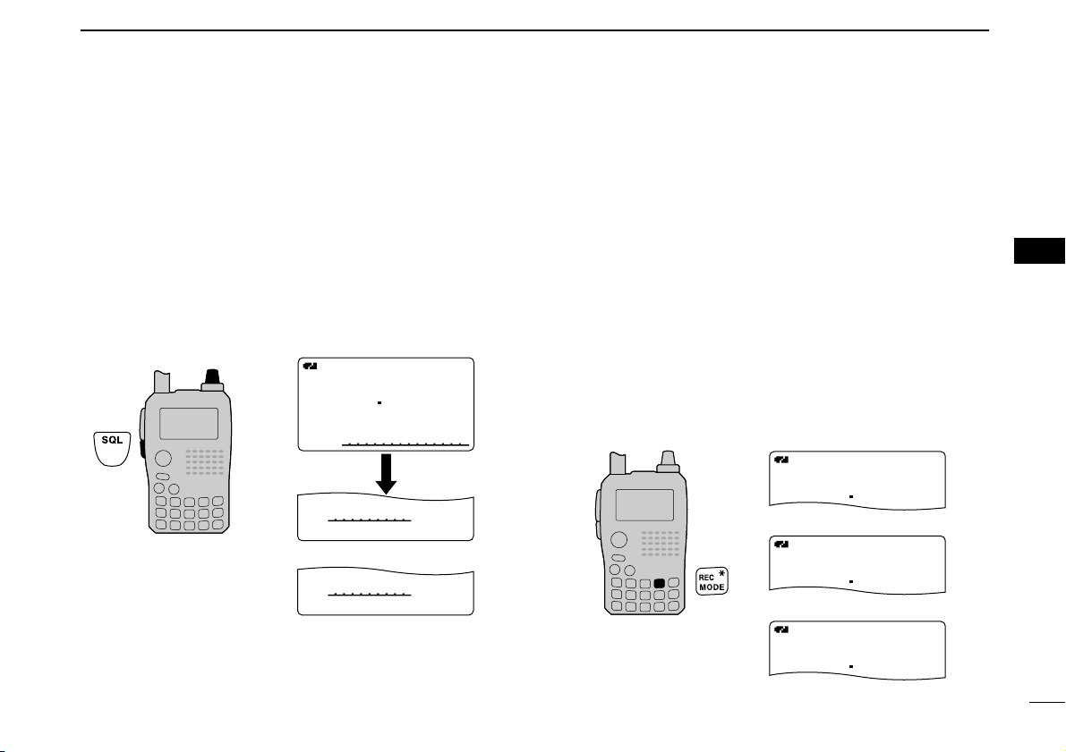
■ Monitor function
This function is used to listen to weak signals without disturbing the squelch setting or to open the squelch manually even
when mute functions such as the tone squelch are in use.
➥ Push and hold [SQL] to monitor the operating frequency.
• The 1st segment of the S-meter blinks.
The [SQL] key can be set to ‘sticky’ operation in set mode.
See page 89 for details.
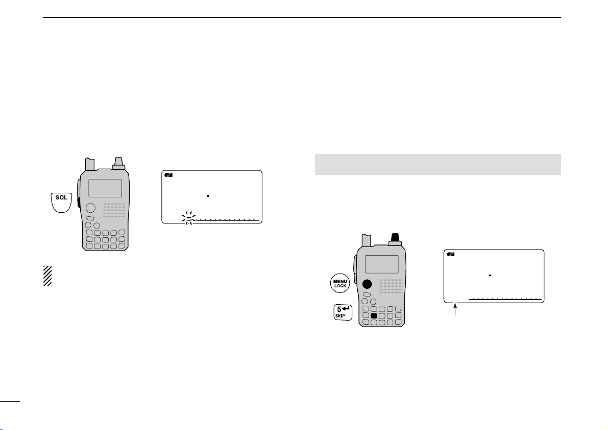
■ Attenuator function
The attenuator prevents a desired signal from distortion by
very strong signals near the desired frequency or when very
strong electric fields, such as from a broadcasting station, are
near your location. The attenuation is about 10 dB.
q Enter “ATTENUATOR” in set mode. (p. 88)
w Rotate [DIAL]†to select “ON” or “OFF.”
e Push [ï](5)
(or [ΩΩ](4)) to return to set mode, and push
[MENU/LOCK] to return to frequency indication.
• “ATT ” appears on the function display when “ON” is selected.
A
MemoName
µ
PRIOPRIO WXWX EMREMR
DTCSDTCS
FMFM
LOWLOW
ATTATT
146 010
P SKIP
+DUP+DUP
25
000000
[DIAL]
Appears.
MENU screen ➪ SET MODE ➪ ATTENUATOR
(Push [MENU/LOCK]) (Rotate [DIAL]†, then push [ï](5)†.)
A
MemoNameMemoName
µ
PRIOPRIO WXWX EMREMR
DTCSDTCS
FMFM
LOWLOW
ATTATT
146 010
P SKIP
+DUP+DUP
25
000000
The 1st segment blinks
†
[DIAL] ↔ [∫∫](2)/[√√](8) [ï](5) ↔ [≈≈](6)
Page 29
23
5
BASIC OPERATION
1
2
3
4
5
6
7
8
9
10
11
12
13
14
15
16
17
18
19
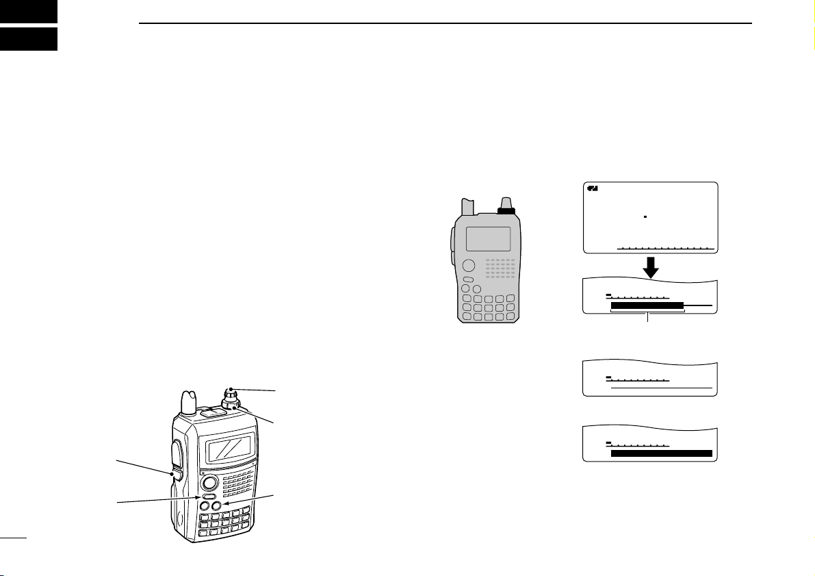
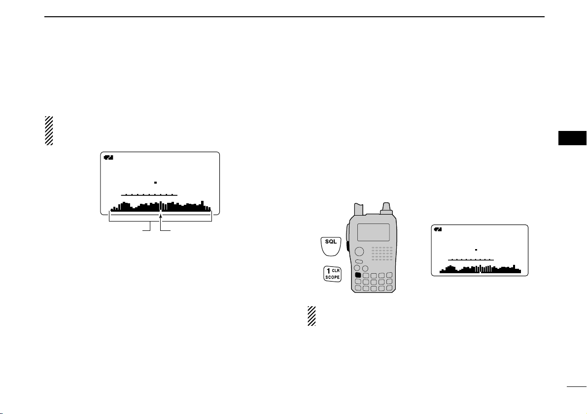
■ Band scope
The band scope function allows you to visually check a specified frequency range around the center frequency.
About the sweep steps: The specified tuning step in each
frequency band
(in VFO mode) or programmed tuning step
(in memory mode) is used during sweep.
DD
Single sweep
q Set the desired frequency as band scope center frequency.
w Push and hold [SCOPE](1) for 1 sec. to start a single
sweep.
• 1 short and 1 long beeps sound.
• Signal conditions (strengths) appear starting from the center of
the range.
e Rotate [DIAL] to set the highlighted cursor to the desired
signal and set the frequency of the signal.
r Push [VFO] to return to normal operation.
DD
Continuous sweep
q Set the desired frequency as band scope center frequency.
w Push and hold [SCOPE](1) for 3 sec. to start continuous
sweep.
• 2 short beeps sound after 1 short and 1 long beeps.
• Signal conditions (strengths) appear starting from the center of
the range.
e Push and hold [SCOPE](1) for 1 sec. to cancel sweep.
• Pushing [SQL] also cancels sweep.
r Push [VFO] to return to normal operation.
The receive audio during sweeping can be muted in
sounds set mode. See page 102 for details.
PRIOPRIO WXWX EMREMR
DTCSDTCS
FMFM
B
A
145 780
P SKIPP SKIP
+DUP+DUP
25
µ
000000
PRIO WX EMR
DTCS
FM
B
A
145 780
P SKIPP SKIP
+DUP
2525
µ
000
Sweep markerBand scope indication
Page 30
24
5 BASIC OPERATION
■ Transmitting
NOTE: To prevent interference, listen on the channel be-
fore transmitting by pushing and holding [SQL].
qSet the operating frequency. (pgs. 18, 19)
• Transmission is available on the 144 MHz/440 MHz amateur
bands only.
• Select output power if desired. See the section at right for details.
wPush and hold [PTT] to transmit.
• Tx/Rx indicator lights red.
• S/RF meter shows the output power level.
eSpeak into the microphone using your normal voice level.
• DO NOT hold the transceiver too close to your mouth or speak
too loudly. This may distort your speech.
rRelease [PTT] to return to receive.
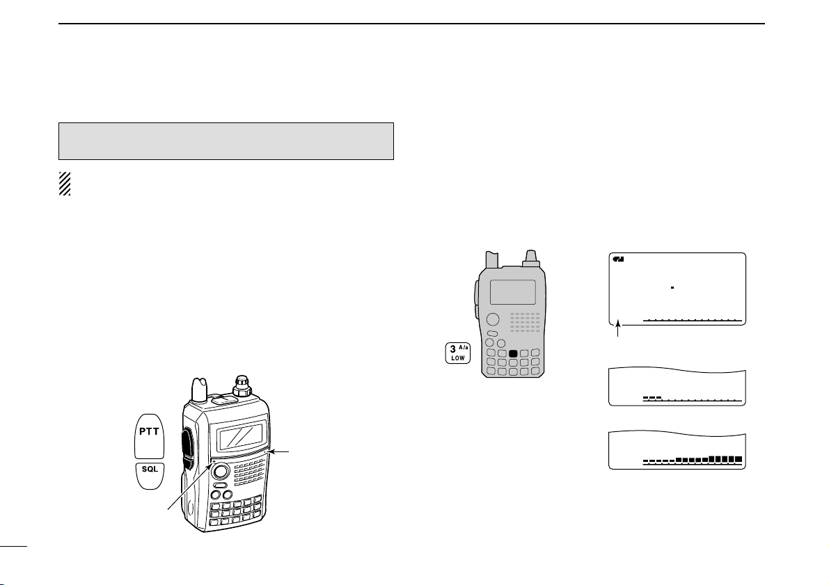
■ Transmit power selection
The transceiver has two output power levels to suit your operating requirements. Low output power during short-range
communications may reduce the possibility of interference to
other stations and will reduce current consumption.
➥
Push and hold [LOW](3) for 1 sec. to toggle the transmit
output power between High and Low.
•“LOW” appears when the low power is selected.
A
MemoName
µ
PRIOPRIO WXWX EMREMR
DTCSDTCS
FMFM
LOWLOW
LOWLOW
LOWLOW
ATTATT
146 010
P SKIP
+DUP+DUP
25
000000
Appears
Low power transmission
High power transmission
Tx/Rx indicator
Microphone
CAUTION: Transmitting without an antenna will damage
the transceiver.
Page 31

25
5
BASIC OPERATION
1
2
3
4
5
6
7
8
9
10
11
12
13
14
15
16
17
18
19
■ Lock function
To prevent accidental frequency changes and unnecessary
function access, use the lock function.
➥ Push and hold [MENU/LOCK] for 1 sec. to turn the lock
function ON and OFF.
•“ ” appears while the lock function is activated.
• The squelch control and volume control can be used while the
lock function is in use with default setting. Either or both the
squelch control and volume control can also be locked in set
mode. (p. 90)
■ Dualwatch operation
Dualwatch operation monitors two frequencies simultaneously. The IC-91A/91AD has two independent receiver circuits as A band and B band
(available frequency bands and
operating mode are different depending on bands).
DD
Dualwatch operation
➥ Push and hold [MAIN/DUAL] for 1 sec. to turn the dual-
watch operation ON and OFF.
• While in dualwatch operation, the display indicates A band in the
upper half and B band in the lower half.
DTCSDTCS
DTCSDTCS
W
PSPS
EM
W
PSPS
FM
PRIOPRIO
PRIOPRIO
+DUP
+DUP
FMFM
146 010
440 000
2525
5050
µ
000
µ
000
A
MemoName
µ
PRIOPRIO WXWX EMREMR
DTCSDTCS
FMFM
LOWLOW
ATTATT
146 010
P SKIP
+DUP+DUP
25
000000
A
MemoNameMemoName
µ
PRIOPRIO WXWX EMREMR
DTCSDTCS
FMFM
LOWLOW
ATTATT
146 010
P SKIP
+DUP+DUP
25
000000
Appears
Page 32

26
5 BASIC OPERATION
DD
Main band selection
➥ Push [MAIN/DUAL] to select A band or B band as the
main operating band alternately.
DD
Setting audio volume
The audio level for dualwatch operation can be adjusted both
on A band and B band simultaneously (default).
This setting can be set separately for each band in sounds
set mode.
qPush and hold [MAIN/DUAL] for 1 sec. to enter the dual-
watch operation, if necessary.
wRotate
[VOL] to adjust the audio level for the main band.
• If squelch is closed, push and hold [SQL] to verify the audio
level.
• The display shows the volume level while setting.
DTCSDTCS
DTCSDTCS
W
PSPS
EM
W
PSPS
FM
PRIOPRIO
PRIOPRIO
+DUP
+DUP
FMFM
146 010
440 000
2525
5050
µ
000
µ
000
DTCS
DTCS
W
PS
EMEM
W
PS
PRIO
PRIO
+DUP+DUP
+DUP+DUP
25
75
µ
000000
µ
000000
146 010
DTCS
DTCS
W
EMEM
W
PS
PRIO
PRIO
+DUP+DUP
+DUP+DUP
25
75
µ
000000
µ
000000
440 000
FMFM
440 000
PSPS
FM
146 010
VOLVOL
VOLVOL
[VOL]
Setting for A band (upper side)
Setting for B band (lower side)
DTCSDTCS
DTCSDTCS
W
PSPS
EM
W
PSPS
FM
PRIOPRIO
PRIOPRIO
+DUP
+DUP
FMFM
146 010
440 000
2525
5050
µ
000
µ
000
DTCSDTCS
DTCSDTCS
W
PSPS
EM
W
PSPS
FM
PRIOPRIO
PRIOPRIO
+DUP
+DUP
FMFM
146 010
440 000
2525
5050
µ
000
µ
000
Page 33

27
5
BASIC OPERATION
1
2
3
4
5
6
7
8
9
10
11
12
13
14
15
16
17
18
19
DD
Volume setting for dualwatch
The volume setting for dualwatch can be set for both bands
simultaneously or for each band separately in set mode.
q Enter “VOLUME SELECT” in sounds set mode. (p. 102)
w Rotate [DIAL]
†
to select “BOTH” or “SEPARATE.”
e Push [ï](5)
(or [ΩΩ](4)) to return to sounds set mode, and
push [MENU/LOCK] to return to frequency indication.
DD
Setting squelch level
qPush and hold [MAIN/DUAL] for 1 sec. to enter the dual-
watch operation, if necessary
wWhile pushing and holding [SQL], rotate [DIAL] to adjust
the main band’s squelch level.
•“LEVEL 1” is loose squelch and “LEVEL 9” is tight squelch.
•“AUTO” indicates automatic level adjustment with a noise pulse
count system.
•“OPEN” indicates continuously open setting.
DTCS
DTCS
W
PS
EMEM
W
PS
PRIO
PRIO
+DUP+DUP
+DUP+DUP
25
75
µ
000000
µ
000000
SQUELCH:AUTO
146 010
DTCS
DTCS
W
EMEM
W
PS
PRIO
PRIO
+DUP+DUP
+DUP+DUP
25
75
µ
000000
µ
000000
SQUELCH:LEVEL6
440 000
FMFM
440 000
PSPS
FM
146 010
DTCSDTCS
DTCSDTCS
W
PSPS
EM
W
PSPS
FM
PRIOPRIO
PRIOPRIO
+DUP
+DUP
FMFM
146 010
440 000
2525
5050
µ
000
µ
000
Setting for A band (Upper)
Setting for B band (Lower)
[DIAL]
MENU screen ➪ SOUNDS ➪ VOLUME SELECT
(Push [MENU/LOCK]) (Rotate [DIAL]†, then push [ï](5)†.)
†
[DIAL] ↔ [∫∫](2)/[√√](8) [ï](5) ↔ [≈≈](6)
Page 34

28
5 BASIC OPERATION
■ TV channel operation
TV channel operation is available only when TV channels are
programmed using the optional RS-91.
(p. 122) Also available
for A band operation only.
D TV channel receiving
q Push [CALL] several times to select TV channels.
•“TV” and channel number appear.
w Rotate [DIAL] to select the desired channel.
• While pushing and holding [BAND], rotating [DIAL] selects the
all channels including skip channel.
D Skip channel setting
Unwanted channels can be skipped for rapid selection, etc.
q Push [CALL] several times to select TV channels.
•“TV” and channel number appear.
w Rotate [DIAL] to select the channel to be skipped.
• To clear the skip setting, rotate [DIAL] while pushing and holding
[BAND] to select a skip channel.
e Push and hold [SKIP](5) for 1 sec. to toggle the skip set-
ting ON and OFF.
•“SKIP” appears when the channel is set as skip channel.
D Automatic TV channel programming
TV channels can be programmed automatically.
q Push [CALL] several times to
select TV channels.
•“TV” and channel number ap-
pear.
w Push [SCAN](2) to start TV
channel programming.
• The programming will automatically stop after scanning all channels.
TVTV
A
MemoName
µ
PRIOPRIO WXWX EMREMR
DTCSDTCS
WFMWFM
LOWLOW
ATTATT
2 ch
P SKIP
+DUP+DUP
25
TVTV
A
MemoName
µ
PRIOPRIO WXWX EMREMR
DTCSDTCS
WFMWFM
LOWLOW
ATTATT
12 ch
P SKIP
+DUP+DUP
25
[DIAL]
Appears
TVTV
A
MemoNameMemoName
µ
PRIOPRIO WXWX EMREMR
DTCSDTCS
WFMWFM
LOWLOW
ATTATT
10 ch
P SKIP
+DUP+DUP
25
TV mode indication
Channel indication
[DIAL]
Page 35

29
6
REPEATER AND DUPLEX OPERATIONS
1
2
3
4
5
6
7
8
9
10
11
12
13
14
15
16
17
18
19
■ Repeater operation
When using a repeater, the transmit frequency is shifted from
the receive frequency by the offset frequency.
(p. 97) It is con-
venient to program repeater information into memory channels.
(p. 66)
q Set the receive frequency (repeater output frequency).
w Set the shift direction of the transmit frequency.
(–DUP or
+DUP; see p. 31 for details.)
• When the auto repeater function is in use (U.S.A. and Korean
versions only), this selection and step e are not necessary.
(p. 32)
e Push and hold [TONE](7) for 1
sec. to activate the subaudible
tone encoder, according to repeater requirements.
•“TONE” appears.
Refer to p. 107 for tone frequency
settings.
r Push and hold [PTT] to transmit.
• The displayed frequency automati-
cally changes to the transmit frequency (repeater input frequency).
• If “OFF” appears, check the offset frequency or shift direction.
(p. 30)
t Release [PTT] to receive.
y Push and hold [SQL] to check whether the other station’s
transmit signal can be directly received or not.
U.S.A. and Korean versions:
Auto repeater function uses standard values of the repeater tone frequency and offset frequency.
While receiving
While transmitting
A
TONE
FM
145
P SKIP
-DUP
A
TONE
FM
144700
P SKIP
-DUP
300
A
TONETONE
FMFM
145300
-DUP-DUP
“–DUP”or “+DUP” appears.
Station A
Station B
Repeater
145.300 MHz
144.700 MHz
144.700 MHz
145.300 MHz
Uplink
Downlink
(transmitting freq.)
(receiving freq.)
Page 36

30
6 REPEATER AND DUPLEX OPERATIONS
D Checking the repeater input signal
The transceiver can check whether the other station’s transmit signal can be received directly or not, by listening on the
repeater input frequency.
➥ Push and hold [SQL] to check whether the other station’s
transmit signal can be directly received or not.
• When the other station’s signal can be directly received, move
to a non-repeater frequency to use simplex. (duplex OFF)
DD
Off band indication
If the transmit frequency is out of the amateur band, the off
band indication, “OFF,” appears on the display when [PTT] is
pushed. Check the offset frequency or duplex direction in this
case.
(p. 31)
U.S.A. and Korean versions:
Auto repeater function uses standard values of the offset
frequency.
✔
CONVENIENT!
Tone scan function: When you don’t know the subaudible
tone used for a repeater, the tone scan is convenient for detecting the tone frequency.
➥ Push and hold [T.SCAN](9) for 1 sec. to start the tone
scan. See p. 112 for more information.
A
OFFOFF
TONETONE
FMFM
P SKIPSKIP
-DUP-DUP
Indication while receiving.
Receives –0.6 MHz shift frequency.
Blinks while pushing and holding [SQL].
A
TONE
FM
145300
P SKIP
-DUP
A
TONE
FM
144 700
P SKIP
-DUP
Push and hold
Page 37

31
6
REPEATER AND DUPLEX OPERATIONS
1
2
3
4
5
6
7
8
9
10
11
12
13
14
15
16
17
18
19
■ Duplex operation
D Setting offset frequency
q Enter “OFFSET FREQ” in DUP/TONE… set mode. (p. 97)
w Rotate [DIAL]
†
to set offset frequency.
• 1 MHz and 10 MHz tuning steps are available by pushing and
holding [MHz](VFO) for 1 sec.: push [MHz](VFO) to cancel it.
e Push [ï](5) (or [
ΩΩ
](4)) to return to DUP/TONE… set mode,
and push [MENU/LOCK] to return to frequency indication.
D Setting duplex direction
➥ Push and hold [DUP](4) for 1 sec. to select “–DUP” or
“+DUP”.
•“–DUP” or “+DUP” indicates the transmit frequency for minus
shift or plus shift, respectively.
• When offset frequency is 0.6 MHz.
U.S.A. and Korean versions:
Auto repeater function has priority over the manual duplex
setting. If the frequency changes after setting, the auto repeater function may have changed the duplex setting.
–Duplex example +Duplex example
Receiving
Transmitting
A
TONETONE
FMFM
145300
PSKIPSKIP
-DUP-DUP
A
TONETONE
FMFM
144700
PSKIPSKIP
-DUP-DUP
Receiving
Transmitting
A
TONETONE
FMFM
145300
PSKIPSKIP
+DUP+DUP
A
TONETONE
FMFM
145900
PSKIPSKIP
+DUP+DUP
5.0 MHz offset
No offset frequency
5.000.00 5.000.00
OFFSET FREQ
0.000.00 0.000.00
OFFSET FREQ
MENU screen ➪ DUP/TONE… ➪ OFFSET FREQ
(Push [MENU/LOCK]) (Rotate [DIAL]†, then push [ï](5)†.)
Although [DIAL] and [ï](5) are used for description in this
section, [∫∫](2)/[√√](8) and [≈≈](6) are available instead of
[DIAL] and [ï](5).
†
[DIAL] ↔ [∫∫](2)/[√√](8) [ï](5) ↔ [≈≈](6)
Page 38

32
6 REPEATER AND DUPLEX OPERATIONS
■ Auto repeater function
The U.S.A. and Korean versions automatically use standard
repeater settings
(duplex ON/OFF, duplex direction, tone encoder
ON/OFF) when the operating frequency falls within or outside
of the general repeater output frequency range. The offset
and repeater tone frequencies are not changed by the auto
repeater function, reset these frequencies, if necessary.
D Frequency range and offset direction
• U.S.A. version
• Korean version
q Enter “AUTO RPT” in set mode. (p. 89)
w Rotate [DIAL]
†
to select the auto repeater setting.
[U.S.A. version]:
•“RPT1” : Activates duplex only. (default)
•“RPT2” : Activates duplex and tone.
•“OFF” : Auto repeater function is turned OFF.
[Korean version]:
•“ON” : Activates duplex and tone. (default)
•“OFF” : Auto repeater function is turned OFF.
e Push [ï](5) (or [
ΩΩ
](4)) to return to set mode, and push
[MENU/LOCK] to return to frequency indication.
MENU screen ➪ SET MODE ➪ AUTO RPT
(Push [MENU/LOCK]) (Rotate [DIAL]†, then push [ï](5)†.)
U.S.A./KOREAN versions only
FREQUENCY RANGE SHIFT DIRECTION
439.000–440.000 MHz “–DUP” appears
FREQUENCY RANGE SHIFT DIRECTION
147.000–147.395 MHz “+DUP” appears
442.000–444.995 MHz “+DUP” appears
447.000–449.995 MHz “–DUP” appears
145.200–145.495 MHz
146.610–146.995 MHz
“–DUP” appears
Page 39

33
6
REPEATER AND DUPLEX OPERATIONS
1
2
3
4
5
6
7
8
9
10
11
12
13
14
15
16
17
18
19
■ 1750 Hz tone
Some European repeaters require a 1750 Hz tone burst to be
accessed. For such European repeaters, perform the following.
• This tone can be use as a ‘Call signal’ in countries out of Europe.
q Push and hold [DTMF.M](.) for 1 sec. to select DTMF
memory.
w Rotate [DIAL]
†
counter-clockwise until “T-CALL” appears.
e Push [ï](5) to set.
r Push [VFO] to exit DTMF memory.
t Set the receive frequency
(repeater output frequency).
y Set the shift direction of the transmit frequency.
(–DUP or
+DUP; see p. 31 for details.)
u While pushing [PTT], push [SQL] to transmit a 1750 Hz
tone burst signal.
• If “OFF” appears, check the offset frequency or shift direction.
(p. 97)
• The displayed frequency automatically changes to the transmit
frequency (repeater input frequency).
i Push and hold [PTT] to transmit.
o Release [PTT] to receive.
!0 Push and hold [SQL] to check whether the other station’s
transmit signal can be received directly or not, by listening
on the repeater input frequency.
r
T-CALLT-CALL
DTMF MEMORY
r
Ch01Ch01
DTMF MEMORY
†
[DIAL] ↔ [∫∫](2)/[√√](8)
Page 40

34
DV MODE OPERATION (Optional UT-121 is required for IC-91A)
7
■ Digital mode operation
The IC-91A*/91AD can be operated in digital voice mode and
low-speed data operation for both transmit and receive. It can
also be connected to a GPS receiver
(compatible with an RS-
232 output/NMEA format/4800 bps) and transmit/receive position
data.
*The optional UT-121 is required for the IC-91A.
■ Call sign programming
Four types of call sign memories are available; your own call
sign “MY CALL SIGN,” other station call sign “YOUR CALL
SIGN,” repeater call sign “RPT1 CALL SIGN” and “RPT2
CALL SIGN.” “MY CALL SIGN” can store up to 6 call signs,
“YOUR CALL SIGN” can store up to 60 call signs and
“RPT1/2 CALL SIGN” can store up to 60 call signs, and each
call sign can be programmed with up to 8 characters.
DD
Your own call sign programming
Your own call sign must be programmed for both digital voice
and low-speed data communications
(including GPS transmis-
sion).
q Select B band as the main band.
(p. 14)
w Enter “MY” in call sign set mode.
• MY CALL SIGN screen is displayed.
e Rotate [DIAL]†to select the desired call sign memory,
“M01” to “M06.”
r Push [≈≈](6) to enter call sign programming mode.
• The 1st digit blinks.
t Rotate [DIAL]†to select the desired character or code.
• Push [A/a](3) to change the character group from “AB” (alphabetical characters; capital letters), “12” (numbers) and “/” (symbols) in sequence.
M01M01
†
/
MY CALL SIGN
r
:SET:SET
:SEL:SEL
:CUR:CUR
CLR:CLRCLR:CLR
A/a:CHARA/a:CHAR
AB
M01M01
/
:SET
:BACK
:SEL
:EDIT
CLR:CLR
MY CALL SIGN
r
MENU screen ➪ CALL SIGN ➪ MY
(Push [MENU/LOCK]) (Rotate [DIAL]†, then push [ï](5)†.)
Although [DIAL] and [ï](5) are used for description in this
section, [∫∫](2)/[√√](8) and [≈≈](6) are available instead of
[DIAL] and [ï](5).
Page 41

35
7
DV MODE OPERATION (Optional UT-121 is required for IC-91A)
7
y Push [≈≈](6) to select 2nd digit, then rotate [DIAL]†to se-
lect the desired character or code.
• Push [≈≈](6) to move the cursor right; push [ΩΩ](4) to move the
cursor left.
• 2nd digit blinks (1st digit stops blinking).
u Repeat the steps t and y to enter your own call sign.
• Up to a 8-digit of call sign can be set.
• If an un-necessary character is entered, push [≈≈](6) or [ΩΩ](4) to
select the character, then push [CLR](1) to erase the selected
character, or push and hold [CLR](1) for 1 sec. to erase all characters following the cursor.
• When programming a note (Up to a 4-digit for operating radio
type or area, etc.), go to step i, otherwise go to step !0.
i Push [≈≈](6) several times to set the cursor beside “/” indi-
cation.
o Repeat steps t to y to program the desired 4-character
note.
!0 Push [ï](5) to store the programmed call sign with note
and returns to MY CALL SIGN screen.
!1 Push [MENU/LOCK] to return to frequency indication.
M01M01
MYCALL MYCALL
/IC91 /IC91
:SET
:BACK
:SEL
:EDIT
CLR:CLR
MY CALL SIGN
r
M01M01
M†
/
MY CALL SIGN
r
:SET:SET
:SEL:SEL
:CUR:CUR
CLR:CLRCLR:CLR
A/a:CHARA/a:CHAR
AB
†
[DIAL] ↔ [∫∫](2)/[√√](8) [ï](5) ↔ [≈≈](6)
1
2
3
4
5
6
8
9
10
11
12
13
14
15
16
17
18
19
Page 42

36
7 DV MODE OPERATION (Optional UT-121 is required for IC-91A)
DD
Station call sign programming
Station call sign must be programmed for the specified station call as well as repeater operation in both digital voice and
low-speed data communications.
q Select B band as the main band.
(p. 14)
w Enter “UR” in call sign set mode.
• YOUR CALL SIGN screen is displayed.
e Rotate [DIAL]†to select the desired call sign memory,
“U01” to “U60.”
r Push [≈≈](6) to enter call sign programming mode.
• The 1st digit blinks.
t Rotate [DIAL]†to select the desired character or code.
• Push [A/a](3) to change the character group from “AB” (alphabetical characters; capital letters), “12” (numbers) and “/” (symbols) in sequence.
y Push [≈≈](6) to select 2nd digit, then rotate [DIAL]†to se-
lect the desired character or code.
• Push [≈≈](6) to move the cursor right; push [ΩΩ](4) to move the
cursor left.
• 2nd digit blinks (1st digit stops blinking).
u Repeat the steps t and y to enter the desired station call
sign.
• Up to an 8-digit of call sign can be set.
• If an un-necessary character is entered, push [≈≈](6) or [ΩΩ](4) to
select the character, then push [CLR](1) to erase the selected
character, or push and hold [CLR](1) for 1 sec. to erase all characters following the cursor.
i Push [ï](5) to store the programmed call sign and returns
to YOUR CALL SIGN screen.
o Push [MENU/LOCK] to return to frequency indication.
U01U01
STATION1 STATION1
:SET
:BACK
:SEL
:EDIT
CLR:CLR
YOUR CALL SIGN
r
U01 AB
S†
:SET:SET
:SEL:SEL
:CUR:CUR
CLR:CLRCLR:CLR
A/a:CHARA/a:CHAR
0:CQ0:CQ
YOUR CALL SIGNYOUR CALL SIGN
r
U01U01 ABAB
†
:SET:SET
:SEL:SEL
:CUR:CUR
CLR:CLRCLR:CLR
A/a:CHARA/a:CHAR
0:CQ0:CQ
YOUR CALL SIGNYOUR CALL SIGN
r
U
CQCQCQ CQCQCQ
:SET
:BACK
:SEL
:EDIT
CLR:CLR
YOUR CALL SIGN
r
MENU screen ➪ CALL SIGN ➪ UR
(Push [MENU/LOCK]) (Rotate [DIAL]†, then push [ï](5)†.)
Page 43

37
7
DV MODE OPERATION (Optional UT-121 is required for IC-91A)
7
NOTE: During the call sign programming mode (r to u),
push [CQ](0) to set “CQCQCQ,” and push [CQ](0) again
to return to the previously stored call sign.
✔
For your information
The IC-91A/91AD has call sign edit record function.
When editing a call sign stored in a call sign memory, regular
memory or call channel, the default setting is to store the
edited call sign into a blank channel automatically. (“FULL” is
displayed when all call sign memory is programmed.)
The edited call sign can be over-written when the setting of
the EDIT RECORD is set to OFF or SELECT.
(p. 95)
However, you must manually over-write a programmed call
sign in regular memory and call channels. (Temporary operation without over-writing is possible.)
†
[DIAL] ↔ [∫∫](2)/[√√](8) [ï](5) ↔ [≈≈](6)
1
2
3
4
5
6
8
9
10
11
12
13
14
15
16
17
18
19
Page 44

38
7 DV MODE OPERATION (Optional UT-121 is required for IC-91A)
■ Digital voice mode operation
qSet the desired frequency in B band. (pgs. 14, 18)
• Select output power, if desired. (p. 24)
wSelect DV mode. (p. 21)
eSet your own call sign for DV operation as follows.
zEnter “MY” in call sign set mode.
xRotate [DIAL]
†
to select the desired your own call sign
channel
(if you have programmed several call signs) then
push [ï](5) to set the call sign and return to CALL SIGN
screen.
• See page 34 for your own call sign programming details.
rSet the desired call sign as described in “When calling the
desired station
(p. 39)” or “When sending a CQ (p. 39).”
tPush and hold [PTT] to transmit and speak into the micro-
phone at normal voice level.
• Tx/Rx indicator lights red and the RF meter shows the output
power.
yRelease [PTT] to return to receive.
• The other station call sign will be received.
• Received call signs can be stored into the received call record
automatically. See page 93 for details.
NOTE: The digital mode operation is vastly different from
FM mode. One of the differences is in digital mode the
squelch does not function as in FM mode. Changing the
squelch setting will not open it to hear the hiss of “White
Noise.” It only activates for digital squelch functions such
as CSQL
(Digital code squelch) or DSQL
(Digital call sign
squelch)
.
UR:UR:
R1:R1:
R2:NOT USE*R2:NOT USE*
MY:MYCALLMY:MYCALL
/IC91 /IC91
CALL SIGN
r
MENU screen ➪ CALL SIGN ➪ MY
(Push [MENU/LOCK]) (Rotate [DIAL]†, then push [ï](5)†.)
Page 45

39
7
DV MODE OPERATION (Optional UT-121 is required for IC-91A)
7
DD
When calling the desired station
Continued instruction from step x on page 38.
cRotate [DIAL]
†
to select “UR,” then push [ï](5)†.
• YOUR CALL SIGN screen is displayed.
vRotate [DIAL]†to select the call sign channel in which de-
sired station’s call sign is programmed.
• See page 36 for station call sign programming details.
bPush [ï](5) to set the station’s call sign and return to
CALL SIGN screen.
nPush [MENU/LOCK] to return to frequency indication.
mPerform the instruction steps t and y on page 38.
DD
When sending a CQ
Continued instruction from step x on page 38.
cRotate [DIAL]
†
to select “UR,” then push [ï](5)†.
• YOUR CALL SIGN screen is displayed.
vRotate [DIAL]†to select the call sign channel in which
“CQCQCQ” is programmed.
Or, select “U” then push [≈≈](6) and [CQ](0) in sequence to
set “CQCQCQ.”
bPush [ï](5) to set “CQCQCQ” as the call sign and return
to CALL SIGN screen.
nPush [MENU/LOCK] to return to frequency indication.
mPerform the instruction step t and y on page 38.
UR:CQCQCQUR:CQCQCQ
R1:R1:
R2:NOT USE*R2:NOT USE*
MY:MYCALLMY:MYCALL
/IC91 /IC91
CALL SIGN
r
UR:STATION1UR:STATION1
R1:R1:
R2:NOT USE*R2:NOT USE*
MY:MYCALLMY:MYCALL
/IC91 /IC91
CALL SIGN
r
†
[DIAL] ↔ [∫∫](2)/[√√](8) [ï](5) ↔ [≈≈](6)
1
2
3
4
5
6
8
9
10
11
12
13
14
15
16
17
18
19
Page 46

40
7 DV MODE OPERATION (Optional UT-121 is required for IC-91A)
■ About D-STAR system
In the D-STAR system, repeater linking via a 10 GHz band
backbone and internet network (gateway connection) capabilities are available. This system provides you to with much
wider coverage range during digital voice mode operation.
• D-STAR system outline
For current repeater operation, stations that are communicating must both be in the same repeater’s operating area.
However, in the D-STAR system as in the illustration at left,
the repeaters can be linked via the system repeaters (with a
10 GHz signal). Thus stations A and B can communicate even
though they are in different repeater operating areas.
Also, the D-STAR system repeaters are connectable through
the internet— gateway connection capability.
For example, when station B uses the gateway connection
station B can communicate with the station C!
By using the gateway connection, long distance communication like DX operation may be possible with 144 or 440 MHz
digital voice!
In the D-STAR system, an independent repeater’s operating
area is called an Area and a group that of linked repeaters via
a 10 GHz backbone is called a Zone.
Station
A
Station C
Station D
Repeater A
Repeater D
440 MHz
440 MHz
Repeater C
10 GHz
Station
B
Repeater B
10 GHz
440 MHz
440 MHz
Internet
network
Internet
network
About time-out timer function
The IC-91A/91AD has a time-out timer function for digital
repeater operation. The timer limits a continuous transmission for approx. 10 min. Warning beeps will sound before
30 sec. (approx.) and just before the timer functioning.
Page 47

41
7
DV MODE OPERATION (Optional UT-121 is required for IC-91A)
7
■ Digital repeater operation
Repeater call signs must be programmed for repeater operation in both digital voice and low-speed data communications.
DD
Repeater call sign programming
q Select B band as the main band. (p. 14)
w Enter “R1” or “R2” in call sign set mode.
• RPT1 or RPT2 CALL SIGN screen is displayed.
e Rotate [DIAL]†to select the desired call sign memory,
“R01” to “R60.”
r Push [≈≈](6) to enter call sign programming mode.
• The 1st digit blinks.
t Rotate [DIAL]†to select the desired character or code.
• Push [A/a](3) to change the character group from “AB” (alpha-
betical characters; capital letters), “12” (numbers) and “/” (symbols) in sequence.
• Set “/” at the 1st digit then set the desired area repeater’s call
sign (in a different zone) for CQ call (“/” stands for “CQCQCQ”) in
a different zone operation. (p. 44)
y Push [≈≈](6) to select 2nd digit, then rotate [DIAL]†to se-
lect the desired character or code.
• Push [≈≈](6) to move the cursor right; push [ΩΩ](4) to move the
cursor left.
• 2nd digit blinks (1st digit stops blinking).
u Repeat the steps t and y to enter the desired repeater
call sign.
• Up to an 8-digit of call sign can be set.
• Push [7] when setting with the gateway connection if the se-
lected repeater has gateway capability. (The gateway connection can be set in RPT1 only when “NOT USE✱” is set to RPT2.)
• If an un-necessary character is entered, push [≈≈](6) or [ΩΩ](4) to
select the character, then push [CLR](1) to erase the selected
character, or push and hold [CLR](1) for 1 sec. to all characters
following the cursor.
i Push [ï](5) to store the programmed call sign and returns
to RPT1 or RPT2 CALL SIGN screen.
o Push [MENU/LOCK] to return to frequency indication.
R01R01
RPT1AA G RPT1AA G
:SET
:BACK
:SEL
:EDIT
CLR:CLR
RPT1 CALL SIGN
r
MENU screen ➪ CALL SIGN ➪ R1/R2
(Push [MENU/LOCK]) (Rotate [DIAL]†, then push [ï](5)†.)
†
[DIAL] ↔ [∫∫](2)/[√√](8) [ï](5) ↔ [≈≈](6)
1
2
3
4
5
6
8
9
10
11
12
13
14
15
16
17
18
19
Page 48

42
7 DV MODE OPERATION (Optional UT-121 is required for IC-91A)
DD
Repeater operation in the same zone
qSet the desired repeater’s frequency, offset and shift direc-
tion in B band.
(pgs. 18, 31)
• Select DV mode in advance. (p. 21)
wSet your own call sign. (p. 38)
• See p. 34 for your own call sign programming.
eSet the desired station call sign. (p. 39)
• See p. 36 for station call sign programming.
rSet the repeater’s call sign as follows;
zEnter “R1” in call sign set mode.
xRotate [DIAL]
†
to select the nearest repeater’s call sign.
cPush [ï](5) to set the call sign for “R1.”
• Return to CALL SIGN screen.
vRotate [DIAL]†to select “R2” then push [ï](5)†.
• RPT2 CALL SIGN screen is displayed.
bRotate [DIAL]†to select the desired repeater’s (in the
same zone) call sign.
• Select “NOT USE✱” when not operating RPT2.
nPush [ï](5) to set the call sign for “R2.”
• Return to CALL SIGN screen.
mPush [MENU/LOCK] to return to frequency indication.
tPush [PTT] to transmit; release to receive.
UR:CQCQCQUR:CQCQCQ
R1:RPT1AAR1:RPT1AA
R2:NOT USE*R2:NOT USE*
MY:MYCALLMY:MYCALL
/IC91 /IC91
CALL SIGN
r
MENU screen ➪ CALL SIGN ➪ R1
(Push [MENU/LOCK]) (Rotate [DIAL]†, then push [ï](5)†.)
†
[DIAL] ↔ [∫∫](2)/[√√](8) [ï](5) ↔ [≈≈](6)
Page 49

43
7
DV MODE OPERATION (Optional UT-121 is required for IC-91A)
7
Area 1
Zone
to another Zone
• Setting example 1
Repeater 1
: A11111
Area 2 Repeater 2
: A22222
Area 3
(Gateway)
Repeater 3
: A33333
Area 4 Repeater 4
: A44444
✔
What is the area?
The Area is the communication range that is
covered by a local repeater.
A Local repeater is called an area repeater in
the D-STAR system.
✔
What is the zone?
The Zone is composed of several areas, that
are linked by the 10 GHz microwave signal.
The areas 1 to 4 make up a zone in the example above.
Station A
:A2222A
Station B
: A2222B
Station C
: A4444C
Internet
network
Internet
network
❑ The setting when Station A is call-
ing Station B
UR : A2222B
R1 : A22222
R2 : NOT USEQ
MY : A2222A
❑ The setting when Station A is mak-
ing a CQ call in area 1
UR : CQCQCQ
R1 : A22222
R2 : A 11111
MY : A2222A
❑ The setting when Station A is call-
ing Station C
UR : A4444C
R1 : A22222
R2 : A44444
MY : A2222A
1
2
3
4
5
6
8
9
10
11
12
13
14
15
16
17
18
19
Page 50

44
7 DV MODE OPERATION (Optional UT-121 is required for IC-91A)
DD
Repeater operation into another zone
qSet the desired repeater’s frequency, offset and shift direc-
tion in B band.
(pgs. 18, 31)
• Select DV mode in advance.
wSet your own call sign. (p. 38)
• See p. 34 for your own call sign programming.
eSet the desired station call sign. (p. 39)
• When making a CQ call
Set the desired repeater’s
(in a different zone) call sign with
a “/” symbol at the 1st digit, for the area in which you
want to make a CQ call, into “UR.”
• See p. 36 for station call sign programming.
rSet the repeater’s call sign as follows;
zEnter “R1” in call sign set mode.
xRotate [DIAL]
†
to select the nearest repeater’s call sign.
• If the nearest repeater is gateway repeater, select the re-
peater’s call sign with “G” setting at the 8th digit.
cPush [ï](5) to set the call sign for “R1.”
• Return to CALL SIGN screen.
vRotate [DIAL]†to select “R2” then push [ï](5)†.
bRotate [DIAL]
†
to select the gateway repeater’s (in the
same zone) call sign.
• The call sign should have “G” setting at the 8th digit.
• When gateway repeater call sign is set in “R1,” select “NOT
USE✱” for “R2” setting.
nPush [ï](5) to set the call sign for “R2.”
• Return to CALL SIGN screen.
mPush [MENU/LOCK] to return to frequency indication.
tPush [PTT] to transmit; release to receive.
UR:CQCQCQUR:CQCQCQ
R1:RPT1AAR1:RPT1AA
R2:NOT USE*R2:NOT USE*
MY:MYCALLMY:MYCALL
/IC91 /IC91
CALL SIGN
r
MENU screen ➪ CALL SIGN ➪ R1
(Push [MENU/LOCK]) (Rotate [DIAL]†, then push [ï](5)†.)
†
[DIAL] ↔ [∫∫](2)/[√√](8) [ï](5) ↔ [≈≈](6)
Page 51

45
7
DV MODE OPERATION (Optional UT-121 is required for IC-91A)
7
Area 1
Zone A
• Setting example 2
Repeater 1
: A11111
Area 2
Repeater 2
: A22222
Area 3
(Gateway)
Repeater 3
: A33333
Repeater 3 3
: A33333
Repeater 3
: A33333
Area 4
Repeater 4
: A44444
Zone B
Area 6
Repeater 6
: B66666
Area 7
(Gateway)
Repeater 7
: B77777
Area 8
Repeater 8
: B88888
Area 5
Repeater 5
: B55555
Station C
: B6666C
Station A
: A2222A
Station B
: A3333B
Internet
network
Internet
network
❑ The setting when Station A is call-
ing Station C
UR : B6666C
R1 : A22222
R2 : A33333 G
MY : A2222A
❑ The setting when Station A is mak-
ing a CQ call in area 8
UR : /B88888
R1 : A22222
R2 : A33333 G
MY : A2222A
❑ The setting when Station B is call-
ing Station C
UR : B6666C
R1 : A33333 G
R2 : NOT USE✱
MY : A3333B
1
2
3
4
5
6
8
9
10
11
12
13
14
15
16
17
18
19
Page 52

46
7 DV MODE OPERATION (Optional UT-121 is required for IC-91A)
■ Received call sign
When a call is received in DV mode, the calling station and
the repeater call signs being used can be stored into the received call record. The stored call signs are viewable in the
following manner.
Up to 20 calls can be recorded.
DD
Desired call record indication
qEnter RX call sign set mode.
• RX CALL SIGN screen is displayed.
wRotate [DIAL]†to select the desired record channel.
eTo confirm the received call, push [ï](5) several times to
select the desired call sign from CALLER, CALLED,
RXRPT1 and RXRPT2.
CALLER : The station call sign that made a call.
CALLED : The station call sign called by the caller.
RXRPT1 : The repeater call sign used by the caller station.
RXRPT2 : The repeater call sign linked from RXRPT1.
rPush [MENU/LOCK] to return to frequency indication.
NOTE: When a call is received in DV mode when the
power save function is activated, the call sign may not be
received correctly.
This is normal, not a malfunction, because of header of the
call sign cannot be detected during power save.
Turn the power save function OFF
(p. 115) if you want to
receive a call sign correctly even in stand-by condition.
✔
For your information
When receiving a call, the received station call sign is automatically displayed and scrolled in sequence at the bottom
line of the function display.
This can be turned OFF in display set mode. (p.100)
RX01RX01
CALLER: CALLER:
AAAAAAAAAAAA
/
:CALLED
:SEL
:COPY CLR:CLR
RX CALL SIGN
r
RX01RX01
CALLED: CALLED:
CQCQCQCQCQCQ
:RXRPT1
:SEL
:COPY CLR:CLR
RX CALL SIGN
r
RX01RX01
RXRPT2: RXRPT2:
:CALLER
:SEL
:COPY CLR:CLR
RX CALL SIGN
r
RX01RX01
RXRPT1: RXRPT1:
:RXRPT2
:SEL
:COPY CLR:CLR
RX CALL SIGN
r
Push
• Station call sign • Called station call sign
• Repeater 1 call sign• Repeater 2 call sign
MENU screen ➪ RX CALL SIGN
(Push [MENU/LOCK]) (Rotate [DIAL]†, then push [ï](5)†.)
†
[DIAL] ↔ [∫∫](2)/[√√](8) [ï](5) ↔ [≈≈](6)
Page 53

47
7
DV MODE OPERATION (Optional UT-121 is required for IC-91A)
7
DD
One-touch reply using the call record
The stored call signs in the call record can be used to the call.
qAfter receiving a call, push and hold [RX➝CS](CALL) for
1 sec.
Or, while pushing and holding [RX➝CS](CALL), rotate
[DIAL] to select the desired call sign record.
• Set your own call sign (MY) in advance. (p. 34)
• The call sign stored in “CALLER” is stored as “UR,” “RXRPT1” is
stored as “R2” and “RXRPT2” is stored as “R1.”
• Error beeps sound when a call sign is received incorrectly, and
no call sign is set in this case.
wPush [PTT] to transmit; release to receive.
✔
For your information
When a call specifying your call sign is received, the call signs
of the calling station and the repeater it is using can be used
for operation automatically.
• When “RX call sign auto write”
(p. 93) is set to “AUTO,” the
station call sign in “CALLER” is set to “UR” automatically.
• When “Repeater call sign auto write” (p. 93) is set to “AUTO,”
the stored station call sign in “RXRPT1” is stored as “R2”
and “RXRPT2” is stored as “R1” automatically.
Important!
Setting call signs with the “One-touch reply using the call
record” operation as at left are for temporary operation only.
Therefore, the set call signs will be overwritten when another call record is used to set call signs.
• Never saved into a call sign memory.
If you want to save the set call signs, see “Copying the call
record contents into call sign memory”
(p. 50) for details.
DV
-DUP
1
2
3
4
5
6
8
9
10
11
12
13
14
15
16
17
18
19
-DUP
DV
B
439 706
AAAAAA
The received call sign is displayed while pushing and
holding [CALL/RX➝CS] when [DIAL] is rotated while
[CALL/RX➝CS] is pushed.
25
Page 54

48
7 DV MODE OPERATION (Optional UT-121 is required for IC-91A)
■ Copying the call sign
DD
Copying the call sign memory contents
This function is convenient when or modifying a part of the
current call sign.
NOTE: Make sure that the “EDIT RECORD” item in DV set
mode is set to “AUTO” or “SELECT” in advance.
(p. 95)
qDuring DV mode operation, enter call sign set mode.
• CALL SIGN screen is displayed.
wRotate [DIAL]†to select “UR,” “R1” or “R2” as desired, then
push [ï](5)
†
.
eRotate [DIAL]
†
to select the desired call sign channel to be
copied.
• U01–U60 and R01–R60 are available.
• When “AUTO” is set to “EDIT RECORD” item
rPush [≈≈](6) to select the call sign programming mode.
• A blank channel is selected automatically.
• The 1st digit of the selected call sign blinks.
tEdit or modify the selected call sign as described in “D Sta-
tion call sign programming”
(p. 36) or “D Repeater call sign
programming”
(p. 41).
yPush [ï](5) to store the edited/modified call sign into the
selected blank channel.
NOTE: The message “FULL” is displayed when no blank
channel is available in station or repeater call sign memory.
Select the desired call sign channel number as described
in step u of “• When “SELECT” is set to “EDIT RECORD”
item” at right-hand page in this case.
U21 AB
†AAAAAAAAAA
:SET:SET
:SEL:SEL
:CUR:CUR
CLR:CLRCLR:CLR
A/a:CHARA/a:CHAR
0:CQ0:CQ
YOUR CALL SIGNYOUR CALL SIGN
r
A blank channel
number blinks.
MENU screen ➪ CALL SIGN
(Push [MENU/LOCK]) (Rotate [DIAL]†, then push [ï](5)†.)
Page 55

49
7
DV MODE OPERATION (Optional UT-121 is required for IC-91A)
7
• When “SELECT” is set to “EDIT RECORD” item
rPush [≈≈](6) to select the call sign programming mode.
• The 1st digit of the selected call sign blinks.
tEdit or modify the selected call sign as described in “D Sta-
tion call sign programming”
(p. 36) or “D Repeater call sign
programming”
(p. 41)
.
yPush [ï](5).
• Call sign channel number blinks.
uRotate [DIAL]†to select the desired call sign channel to
store.
iPush [ï](5) to store the edited/modified call sign into the
selected channel.
U21U21 ABAB
AAAAA1 AAAAA1
:SET:SET
:SEL:SEL
:CUR:CUR
CLR:CLRCLR:CLR
A/a:CHARA/a:CHAR
0:CQ0:CQ
YOUR CALL SIGNYOUR CALL SIGN
r
Call sign channel
number bliks.
†
[DIAL] ↔ [∫∫](2)/[√√](8) [ï](5) ↔ [≈≈](6)
1
2
3
4
5
6
8
9
10
11
12
13
14
15
16
17
18
19
Page 56

50
7 DV MODE OPERATION (Optional UT-121 is required for IC-91A)
DD
Copying the call record contents into call sign memory
This is a way to copying the call record contents (“CALLER,”
“RXRPT1” and “RXRPT2”) into call sign memory (“UR,” “R1” and
“R2”) at the same time or individually.
qPerform the steps q to e of “D Desired call record indica-
tion” (p. 46) to select the desired call record or call sign.
wPush [≈≈](6) to select copy select mode.
• COPY SELECT screen is displayed.
eRotate [DIAL]†to select the desired call sign to be copied
from “ALL,” “RXRPT1” and “RXRPT2.”
•“ALL” selection won’t appear when either station or repeater call
sign memory has no blank channel.
• When “ALL” is selected
➥ Push [≈≈](6) to copy the selected record’s contents into
the appropriate call sign memory.
• Returns to RX CALL SIGN screen automatically.
• When “CALLER,” “RXRPT1” or “RXRPT2” is
selected
z
Push
[≈≈](6) then r
otate [DIAL]†to select the desired condition of call sign memory channel selection to be copied to
from “AUTO” and “LIST SEL.”
•“AUTO” selection won’t appear when the appropriate call sign
memory has no blank channel.
• Go to step r when “AUTO” is selected.
xPush [≈≈](6), then select the desired call sign memory
channel to copy to with [DIAL].
cPush [≈≈](6) to copy the call sign into the selected call
sign memory.
• Returns to RX CALL SIGN screen automatically.
rPush [MENU/LOCK] to return to frequency indication.
RX01RX01
AUTOAUTO
LIST SELLIST SEL
:BACK:BACK
:LIST:LIST
COPY SELECTCOPY SELECT
:SEL:SEL
r
RX01RX01
ALLALL
:BACK:BACK
:LIST:LIST C:CURRC:CURR
COPY SELECTCOPY SELECT
:SEL:SEL
r
†
[DIAL] ↔ [∫∫](2)/[√√](8) [ï](5) ↔ [≈≈](6)
Page 57

51
7
DV MODE OPERATION (Optional UT-121 is required for IC-91A)
7
■ Break-in communication
The break-in function allows you to break into a conversation,
where the two original stations are communicating with call
sign squelch enabled.
qWhile receiving an another station’s communication, push
and hold [RX➝CS](CALL) for 1 sec. to set the communicating station’s call sign.
• When a call sign has not been received correctly, error beeps
sound and no call sign is set. Receive the call sign of a communicating signal again, or set the call sign manually.
wPush and hold [BK](9) for 1 sec. to turn the break-in func-
tion ON.
•“BK” appears.
eWhen both stations are in standby, push [PTT] to transmit
a break-in call.
• The programmed call sign station receives the break-in call as
well as your call sign.
rWait for the reply call from the station who receives the
break-in call.
tAfter receiving the reply call, communicate normally.
yTo cancel the break-in, push and hold [BK](9) for 1 sec. to
turn OFF.
BKBKDVDV
B
LOWLOW
ATTATT
430 712
50
Appears
• How to use the break-in?
While operating with the call sign squelch (p. 110), the
squelch never opens
(no audio sounds) even if a call is re-
ceived, unless your own call sign
(“MY”) is specified.
However, when the call including the “BK ON” signal
(break-
in call) is received, the squelch will open and audio sounds
even if the call is specified for another station.
Station A Station B
Station C
• Station C calling to Station A with “BK OFF”
Station A Station B
Station C
• Station C calling to Station A with “BK ON”
Station A and B are
communicating using the call sign
squelch.
Station A and B are
communicating using the call sign
squelch.
Station B never hears that
Station C is calling Station A.
Station B also hears that Station C is calling Station A.
1
2
3
4
5
6
8
9
10
11
12
13
14
15
16
17
18
19
Page 58

52
7 DV MODE OPERATION (Optional UT-121 is required for IC-91A)
■ Message operation
DD
TX message programming
TX messages are available for up to 5 channels and each
channel can be programmed with a message of up to 20
characters. Available characters are 0 to 9, A to Z
(capital let-
ters), a to z (lower case letters), some symbols and space.
qEnter “TX MESSAGE” in message/position set mode.
• TX MESSAGE screen is displayed.
wRotate [DIAL]†to select the desired transmit message
channel.
• Ch01 to Ch05 and OFF are available.
• Previously message is displayed if programmed.
ePush [≈≈](6) to select the message edit condition.
• The 1st digit of the message blinks.
rRotate [DIAL]†to select the desired character or symbol.
• Push [A/a](3) to change the character group from “AB” (alphabetical characters; capital letters), “ab” (alphabetical characters;
lower case letters), “12” (numbers) and “ !”” (symbols) in se-
quence.
• If an un-necessary character is entered, push [≈≈](6) or [ΩΩ](4) to
select the character, then push [CLR](1) to erase the selected
character, or push and hold [CLR](1) for 1 sec. to erase all characters following the cursor.
tPush [≈≈](6) to select 2nd digit, then rotate [DIAL]†to select
the desired character or code.
• Push [≈≈](6) to move the cursor right; push [ΩΩ](4) to move the
cursor left.
• 2nd digit blinks (1st digit stops blinking).
yRepeat the steps r and t to enter the desired message.
• Up to 20-character messages can be set.
uPush [ï](5) to store the message.
iPush [MENU/LOCK] to return to frequency indication.
Ch01Ch01 !''
Hello!Hello!
†
:SET:SET
:SEL:SEL
:CUR:CUR
CLR:CLRCLR:CLR
A/a:CHARA/a:CHAR
TX MESSAGETX MESSAGE
r
Ch01Ch01
†
:SET:SET :SEL:SEL
:BACK:BACK
CLR:CLRCLR:CLR
TX MESSAGETX MESSAGE
:EDIT:EDIT
r
MENU screen ➪ MESSAGE/POSITION ➪ TX MESSAGE
(Push [MENU/LOCK]) (Rotate [DIAL]†, then push [ï](5)†.)
Page 59

53
7
DV MODE OPERATION (Optional UT-121 is required for IC-91A)
7
DD
Message Transmission
Select the message transmission function ON (Ch01–05) and
OFF. When a message channel is selected, the transceiver
transmits a text message
(pre-programmed). (default: OFF)
qSet the operating frequency, call signs and other settings,
such as repeater, as desired in B band.
wPerform the steps q to e in “D TX message program-
ming” as at left.
eRotate [DIAL]
†
to select the desired message channel.
•“Ch01” to “Ch05” available.
• See left-hand pages for message programming.
rPush [ï](5) to set the message for transmission.
tPush [PTT] to transmit the selected message.
• The message is transmitted each time [PTT] is pushed.
• The message is transmitted each 30 sec. automatically during
continuous transmission.
yRelease [PTT] to return to receive.
uWhen the reply call with a message is received, the call
sign and the message scrolls at the bottom of the function
display.
✔
For your information
The automatic received call sign and/or message indication
can be turned OFF in display set mode, if desired.
➥ RX CALL SIGN
(p. 100)
➥ RX MESSAGE (p. 101)
NOTE: Only 1 message can be stored in the IC91A/91AD. The received message is cleared by turning
power OFF, or overwritten when another message is received.
A transmitted message that includes lower case characters from the IC-91A/91AD may not be decoded and displayed correctly by the ID-800H, IC-V82/U82, etc.
DVDV
B
430 712
50
MSG:Hello!
Scrolls the received message.
†
[DIAL] ↔ [∫∫](2)/[√√](8) [ï](5) ↔ [≈≈](6)
1
2
3
4
5
6
8
9
10
11
12
13
14
15
16
17
18
19
Page 60

54
7 DV MODE OPERATION (Optional UT-121 is required for IC-91A)
DD
RX message indication
The received message can also be checked in DV set mode.
qSelect “RX MESSAGE” in message/position set mode.
• The received message is displayed in RX MESSAGE screen.
wRotate [DIAL] or push [√√](8) to display the station call
sign.
ePush [ï ](5) or [ΩΩ](4) to return to MESSAGE/POSITION
screen.
rPush [MENU/LOCK] to return to frequency indication.
■ Automatic reply function
The automatic reply function replies to calls by a station that
specified your call sign.
Two methods of replying are available— one is making a
reply call with your own call sign, and other one is making a
reply call with reply voice audio that has been recorded in DV
voice memory.
DD
Automatic reply function setting
qEnter “AUTO REPLY” in DV set mode. (p. 92)
• AUTO REPLY screen is displayed.
wRotate [DIAL]†to select the desired reply condition.
OFF : Deactivate the automatic reply function.
(default)
ON : Reply to the call with your own call sign.
VOICE : Reply to the call with the recorded voice memory.
ePush [ï](5).
• Returns to DV SET MODE screen automatically.
rPush [MENU/LOCK] to return to frequency indication.
OFFOFF
ONON
VOICEVOICE
AUTO REPLY
r
MENU screen ➪ DV SET MODE ➪ AUTO REPLY
(Push [MENU/LOCK]) (Rotate [DIAL]†, then push [ï](5)†.)
CALLER:CALLER:
BBBBBB BBBBBB
/
:MSG:MSG
:BACK:BACK
RX MESSAGERX MESSAGE
r
MESSAGE:MESSAGE:
Hello!Hello!
:CALLER:CALLER
:BACK:BACK
RX MESSAGERX MESSAGE
r
MENU screen ➪ MESSAGE/POSITION ➪ RX MESSAGE
(Push [MENU/LOCK]) (Rotate [DIAL]†, then push [ï](5)†.)
Page 61

55
7
DV MODE OPERATION (Optional UT-121 is required for IC-91A)
7
DD
Voice memory recording for automatic reply
qSelect DV mode in B band, and deactivate the priority
watch
(p. 83) and weather alert function (p. 114) if activated.
wEnter “REPLY VOICE” in DV voice memo set mode.
• REPLY VOICE screen is displayed.
eWhile pushing and holding [PTT], speak into the micro-
phone.
• Up to 10 seconds of message is recordable.
• The recording stops after 10 second or when [PTT] is released.
rPush [ΩΩ](4) to return to DV VOICE MEMO screen.
tPush [MENU/LOCK] to return to frequency indication.
DD
Play-back or erase the voice memory
qPush [MENU/LOCK] to select menu mode indication.
wRotate [DIAL]
†
to select “DV VOICE MEMO,” then push
[ï](5)
†
.
eRotate [DIAL]
†
to select “REPLY VOICE,” then push
[ï](5)
†
.
• REPLY VOICE screen is displayed.
rTo play-back the recorded voice memory, push [ï](5).
• Push [ï](5) again to pause, push [≈≈](6) to cancel the play-back.
tTo erase the recorded voice memory, push and hold
[CLR](1) for 1 sec.
REPLY VREPLY V
PTT:PTT:
●
:BACK:BACK CLR:CLRCLR:CLR
REPLY VOICEREPLY VOICE
:
r
MENU screen ➪ DV VOICE MEMO ➪ REPLY VOICE
(Push [MENU/LOCK]) (Rotate [DIAL]†, then push [ï](5)†.)
IMPORTANT!
Deactivate the dualwatch function and set minimum [VOL]
level when recording the DV voice memo.
Otherwise received audio or unwanted noise from A band is
also recorded into the voice memory.
†
[DIAL] ↔ [∫∫](2)/[√√](8) [ï](5) ↔ [≈≈](6)
1
2
3
4
5
6
8
9
10
11
12
13
14
15
16
17
18
19
Page 62

56
7 DV MODE OPERATION (Optional UT-121 is required for IC-91A)
■ EMR communication
The EMR communication mode is available for digital mode
operation. In the EMR communication mode, no call sign setting is necessary. When an EMR communication mode signal is received, the audio (voice) will be heard at the specified
level even the volume setting level is set to minimum level, or
digital call sign/digital code squelch is in use.
qSet the desired frequency in 144 or 440 MHz band then
push and hold [EMR](.) until 3 short and 1 long beeps
sound to turn the EMR setting ON.
•“EMR” appears
wOperate the transceiver normal way.
eTo cancel the EMR communication mode, push and hold
[EMR](.) for 1 sec. to turn OFF.
■
Low-speed data communication
In addition to the digital voice communication, low-speed data
communication is available.
The optional OPC-1529R
DATA COMMUNICATION CABLE
and se-
rial data communication software
(purchase locally) are re-
quired in addition.
The optional RS-91
REMOTE CONTROL SOFTWARE
(OPC-1529R
supplied) also includes a low-speed data communication ca-
pability.
NOTE: Turn OFF the GPS mode
(p. 58)
in advance to op-
erate the low-speed data communication.
DD
Connection
Connect the transceiver to your PC using with the optional
OPC-1529R as illustrated below.
OPC-1529R
(optional)
to [DATA]
to
RS-232C
EMREMRDVDV
B
430 712
50
Appears
Page 63

57
7
DV MODE OPERATION (Optional UT-121 is required for IC-91A)
7
DD
Low-speed data communication application
setting
Configure the low-speed data communication application as
follows.
• Port : The same COM port number as IC-
91A/91AD’s
• Baud rate : 38.4 kbps
(fixed value)
• Data : 8 bit
• Parity : None
• Stop : 1 bit
• Flow control : Xon/Xoff
DD
Low-speed data communication operation
NOTE: Confirm that in AUTO, the computer controls when
[PTT] is activated to send data and the user doesn’t have
to operate the radio.
qSet your own, station call signs, etc. as described in
“■ Digital voice mode operation”
(p. 38) and “■ Digital re-
peater operation”
(p. 41).
wRefer to the instructions of the low-speed data communi-
cation application.
eTo transmit data
• With your voice audio, push and hold [PTT] to transmit while
sending data from the PC. Release [PTT] to receive.
• Under computer control, see Transmission condition setting at
right.
DD
Transmission condition setting
qEnter “DV DATA TX” in DV set mode. (p. 92)
wRotate [DIAL]†to select “PTT” or “AUTO.”
ePush [ï](5)
(or [ΩΩ](4)) to return to DV set mode, and push
[MENU/LOCK] to return to frequency indication.
MENU screen ➪ DV SET MODE ➪ DV DATA TX
(Push [MENU/LOCK]) (Rotate [DIAL]†, then push [ï](5)†.)
†
[DIAL] ↔ [∫∫](2)/[√√](8) [ï](5) ↔ [≈≈](6)
1
2
3
4
5
6
8
9
10
11
12
13
14
15
16
17
18
19
Page 64

58
7 DV MODE OPERATION (Optional UT-121 is required for IC-91A)
■ GPS operation
During GPS mode operation, a GPS receiver (RS-232C out-
put/NMEA format) can be connected to the [DATA] socket of
the IC-91A/91AD to indicate the current position
(Latitude and
Longitude). The position data is transmitted with your voice sig-
nals at the same time.
In addition, the GPS message transmission is also available
for the GPS mode operation.
DD
Sentence formatter setting
qEnter “GPS MODE” in DV set mode. (p. 94)
• GPS MODE screen is displayed.
wRotate [DIAL]†to select “ON.”
ePush [ï](5)
†
to select GPS SENTENCE screen.
rRotate [DIAL]
†
to select the desired GPS sentence, then
push [ï](5).
• A total 5 sentences, RMC, GGA, GLL, GSA and VTG are available.
tRotate [DIAL]†to turn the sentence usage ON and OFF.
yPush [ï](5)
(or [ΩΩ](4)) to return to GPS SENTENCE
screen.
uRepeat the steps r to y to set another GPS sentence
usage.
• Up to 3 GPS sentences are usable at the same time.
iPush [MENU/LOCK] to return to frequency indication.
OFF
ON
GPS MODEGPS MODE
:SENTENCE:SENTENCE
r
MENU screen ➪ DV SET MODE ➪ GPS MODE
(Push [MENU/LOCK]) (Rotate [DIAL]†, then push [ï](5)†.)
OPC-1529R
(optional)
to [DATA]
to RS-232C port
(null modem
adapter is required)
GPS
receiver
Page 65

59
7
DV MODE OPERATION (Optional UT-121 is required for IC-91A)
7
DD
GPS message programming
qEnter “GPS” in message/position set mode.
• GPS MESSAGE screen is displayed.
wPush [≈≈](6) to select the message edit condition.
• The 1st digit of the message blinks.
eRotate [DIAL]†to select the desired character or symbol.
• Push [A/a](3) to change the character group from “AB” (alphabetical characters; capital letters), “ab” (alphabetical characters;
lower case letters), “12” (numbers) and “ !”” (symbols) in se-
quence.
rPush [≈≈](6) to select 2nd digit, then rotate [DIAL]†to select
the desired character or code.
• Push [≈≈](6) to move the cursor right; push [ΩΩ](4) to move the
cursor left.
• 2nd digit blinks (1st digit stops blinking).
tRepeat the steps r and t to enter the desired message.
• Up to 20-character messages can be set.
yPush [ï](5) to store the message.
uPush [MENU/LOCK] to return to frequency indication.
DATA:DATA: AB
Hello!Hello!
†
:SET:SET
:SEL:SEL
:CUR:CUR
CLR:CLRCLR:CLR
GPS MESSAGEGPS MESSAGE
A/a:CHARA/a:CHAR
r
DATA:DATA: ABAB
†
:SET:SET
:SEL:SEL
:CUR:CUR
CLR:CLRCLR:CLR
GPS MESSAGEGPS MESSAGE
A/a:CHARA/a:CHAR
r
MENU screen ➪ MESSAGE/POSITION ➪ GPS
(Push [MENU/LOCK]) (Rotate [DIAL]†, then push [ï](5)†.)
†
[DIAL] ↔ [∫∫](2)/[√√](8) [ï](5) ↔ [≈≈](6)
1
2
3
4
5
6
8
9
10
11
12
13
14
15
16
17
18
19
Page 66

60
7 DV MODE OPERATION (Optional UT-121 is required for IC-91A)
DD
GPS message automatic transmission
qEnter “GPS AUTO TX” in DV set mode. (p. 95)
• GPS AUTO RX screen is displayed.
wRotate [DIAL]†to select the desired position data transmit-
ting interval from 5 sec., 10 sec., 30 sec., 1 min., 3 min.,
5 min., 10 min., 30 min. and OFF.
• The position data is transmitted only when [PTT] is pushed with
OFF setting, the data is transmitted automatically once every
5 sec., 10 sec., 30 sec., 1 min., 3 min., 5 min., 10 min. and
30 min. when the appropriate setting is selected.
• The GPS message is also transmitted if programmed.
ePush [ï](5) (or [
ΩΩ
](4)) to return to DV SET MODE screen.
rPush [MENU/LOCK] to return to frequency indication.
NOTE: Your own call sign (“MY”) should be set to activate
the GPS automatic transmission.
DD
Position indication
qEnter “POSITION” in message/position set mode.
• GPS POSITION screen is displayed.
wRotate [DIAL]†to select the received position data indica-
tion.
ePush [ï](5)
(or [ΩΩ](4)) to return to MESSAGE/POSITION
screen.
rPush [MENU/LOCK] to return to frequency indication.
MY POSITION
GPS POSITIONGPS POSITION
r
34.56.789 N34.56.789 N
123.45.678 E123.45.678 E
:RX POS:RX POS
:BACK:BACK
MENU screen ➪ MESSAGE/POSITION ➪ POSITION
(Push [MENU/LOCK]) (Rotate [DIAL]†, then push [ï](5)†.)
OFF
5SEC5SEC
10SEC10SEC
30SEC30SEC
1MIN1MIN
GPS AUTO TXGPS AUTO TX
r
MENU screen ➪ DV SET MODE ➪ GPS AUTO TX
(Push [MENU/LOCK]) (Rotate [DIAL]†, then push [ï](5)†.)
Page 67

61
7
DV MODE OPERATION (Optional UT-121 is required for IC-91A)
1
2
3
4
5
6
7
8
9
10
11
12
13
14
15
16
17
18
19
DD
Received GPS message indication
qEnter “RX GPS” in message/position set mode.
• RX GPS MESSAGE screen is displayed.
wPush [ï](5) (or [
ΩΩ
](4)) to return to MESSAGE/POSITION
screen.
ePush [MENU/LOCK] to return to frequency indication.
DATA:DATA:
Call from Call from
Osaka! Osaka!
:BACK:BACK
RX GPS MESSAGERX GPS MESSAGE
r
MENU screen ➪ MESSAGE/POSITION ➪ RX GPS
(Push [MENU/LOCK]) (Rotate [DIAL]†, then push [ï](5)†.)
†
[DIAL] ↔ [∫∫](2)/[√√](8) [ï](5) ↔ [≈≈](6)
Page 68

62
7 DV MODE OPERATION (Optional UT-121 is required for IC-91A)
■ Other functions for DV mode operation
DD
DV voice memory
The IC-91A/91AD has a DV voice memory that records a total
30 second
(approx.) of received audio.
The DV voice memory is divided into 2 tracks, 15 seconds
each in a track, as the default setting.
◆ Recording received audio
qSelect DV mode in B band, and deactivate the priority
watch
(p. 83) and weather alert function (p. 114) if activated.
wWhile receiving a DV signal, push [REC].
eRotate [DIAL] to select the desired track.
•“✱” is displayed beside the track number when the selected track
has been recorded.
rPush [REC] to start recording.
• Track counter (bar meter) is displayed during record.
• The recording is paused automatically when the DV signal is in-
terrupted or when the DV audio signal cannot be received correctly. Re-starts the recording when the DV audio signal is
received correctly.
tPush [REC] again to stop recording.
• The recording stops automatically when the track becomes full.
◆ Track size setting
The track size can be changed with the following instruction.
qEnter “TRACK SIZE” in DV voice memo set mode.
• TRACK SIZE screen is displayed
wRotate [DIAL]†to select the desired track size.
10S/3TRACK : Makes 3 tracks and 10 seconds audio
can be recorded in each track.
15S/2TRACK : Makes 2 tracks and 15 seconds audio
can be recorded in each track.
30S/1TRACK : Makes 1 track only and 30 seconds audio
can be recorded in a track.
ePush [ï](5)
(or [ΩΩ](4)) to return to DV VOICE MEMO
screen.
rPush [MENU/LOCK] to return to frequency indication.
10S/3TRACK10S/3TRACK
15S/2TRACK15S/2TRACK
30S/1TRACK30S/1TRACK
TRACK SIZETRACK SIZE
r
MENU screen ➪ DV VOICE MEMO ➪ TRACK SIZE
(Push [MENU/LOCK]) (Rotate [DIAL]†, then push [ï](5)†.)
DVDV
B
440 012
50
qREC TRACK:2
Page 69

63
7
DV MODE OPERATION (Optional UT-121 is required for IC-91A)
1
2
3
4
5
6
7
8
9
10
11
12
13
14
15
16
17
18
19
◆ Playing-back and erasing the recorded audio
qSelect DV mode in B band, and deactivate the priority
watch
(p. 83) and weather alert function (p. 114) if activated.
wEnter “TRACK” in DV voice memo set mode.
• TRACK screen is displayed
eRotate [DIAL]†to select the desired audio track to be play-
back or erased.
•“✱” is displayed beside the track number when the selected track
has been recorded.
rPush [ï](5) to play-back the recorded audio.
• Push [ï](5) again to pause, push [≈≈](6) to stop play-back.
tPush and hold [CLR](1) for 1 sec. to erase the recorded
audio.
yPush [ΩΩ](4) to return to DV VOICE MEMO screen.
uPush [MENU/LOCK] to return to frequency indication.
DD
DV automatic detect
The “DV” mode indicator blinks when a non-DV signal is re-
ceived during DV mode operation.
The IC-91A/91AD DV automatic detection monitors in FM
mode when other than DV mode signal is received.
qEnter “AUTO DETECT” in DV set mode.
(p. 95)
wRotate [DIAL]†to turn the DV automatic detect function ON
and OFF.
OFF : “DV” mode indicator blinks, however the trans-
ceiver receives in DV mode even if non-DV mode
signals are received.
ON : “DV” mode indicator blinks and the transceiver
monitors the signal in FM mode.
ePush [ï](5)
(or [ΩΩ](4)) to return to DV SET MODE screen
rPush [MENU/LOCK] to return to frequency indication.
NOTE: The received FM audio may be distorted when re-
ceiving an FM signal with DV automatic detect function.
MENU screen ➪ DV SET MODE ➪ AUTO DETECT
(Push [MENU/LOCK]) (Rotate [DIAL]†, then push [ï](5)†.)
TRACK:1TRACK:1 *
::SEL:SEL
:BACK:BACK CLR:CLRCLR:CLR
TRACKTRACK
r
MENU screen ➪ DV VOICE MEMO ➪ TRACK
(Push [MENU/LOCK]) (Rotate [DIAL]†, then push [ï](5)†.)
†
[DIAL] ↔ [∫∫](2)/[√√](8) [ï](5) ↔ [≈≈](6)
Page 70

64
MEMORY/CALL CHANNELS
8
■ General description
The IC-91A/91AD has 850 memory channels in A band, 450
memory channels in B band, and 2 call channels in each
band. Memory channels in each bands including 50 scan
edge memory channels
(25 pairs) for storage of often-used
frequencies, respectively.
And a total of 26 memory banks, A to Z, are available in each
bands for storing groups of frequencies, etc. Up to 100 channels can be assigned into a bank.
DD
Memory channel contents
The following information can be programmed into memory
channels:
• Operating frequency
(p. 18)
• Operating mode (p. 21)
• Duplex direction (+DUP or –DUP) with an offset frequency
(p. 31)
• Subaudible tone encoder (p. 107), tone squelch or DTCS
squelch ON/OFF
(p. 110)
• Subaudible tone frequency (p. 107), tone squelch fre-
quency or DTCS code with polarity
(pgs. 107, 111)
• Scan skip information (p. 80)
• Memory bank (p. 67)
• Memory name (p. 70)
• Tuning step (p. 18)
• Call sign squelch or Digital code squelch* (p. 110)
• Station call sign* (p. 36)
• RPT1/RPT2 call sign* (p. 41)
*Available for B band operation only.
■ Selecting a memory channel
DD
Using [DIAL]— Programmed channels
qPush [MR] to select memory mode.
wRotate [DIAL] to select the desired memory channel.
• Only programmed channels are displayed.
DD
Using [DIAL]— All channels
qPush [MR] to select memory mode.
wPush and hold [S.MW](MR) for 1 sec. to enter select mem-
ory write mode.
• 1 short and 1 long beep sound.
•“µµ” indicator blinks.
eRotate [DIAL] to select the desired memory channel.
• All channels are displayed.
• Push [VFO] to return to memory mode indication.
[DIAL]
A
µ
FMFM
146 010
000000
Appears
Rotate [DIAL] to select
the memory channel.
Page 71

65
8
MEMORY/CALL CHANNELS
1
2
3
4
5
6
7
8
9
10
11
12
13
14
15
16
17
18
19
DD
Using the KEYPAD
qPush [MR] to select memory mode.
wPush the keypad to enter 3 digits to select the desired
memory channel.
• The blank channels are also selectable.
• Example— selecting memory channel “25”
Push [MR] then push [0], [2], [5].
■ Selecting a call channel
qPush [CALL] to select call channel mode.
• Pushing [CALL] toggles call, TV* and weather†channels.
wRotate [DIAL] to select the desired call channel.
•“C0” and “C1” are selectable.
*Appears only when TV channels are programmed via the
optional RS-91. Also available for A band operation only.
†
Available for the USA version only.
[DIAL]
A
FMFM
440 000
C1C1
A
FMFM
146 010
C0C0
VHF band call channel
UHF band call channel
Appears
A
µ
FMFM
145 600
025025
The entered memory
channel is selected.
Keypad
[DIAL]
146 010
BANK :----
MNAME:
SKIP :OFF
FMFM
r
µ
000
Blinks
Rotate [DIAL] to select
the memory channel.
Page 72

66
8 MEMORY/CALL CHANNELS
■
Memory channel programming
qPush [VFO] to select VFO mode.
wSet the desired frequency:
➥ Select the desired band with [BAND].
➥ Set the desired frequency with [DIAL].
➥ Or set the desired frequency with keypad directly.
In this case, the band and frequency settings with
[BAND] and [DIAL] as above are not required.
➥ Set other data (e.g. offset frequency, duplex direction,
tone squelch, etc.), if desired.
ePush and hold [S.MW](MR) for 1 sec. to enter select mem-
ory write mode.
• 1 short and 1 long beep sound.
•“µµ” indicator blinks.
rRotate [DIAL] to select the desired channel.
• Call channels (C0, C1), VFO (VFO) and scan edge channels
(0A/0B to 24A/24B), as well as regular memory channels, can
be programmed in this way.
tPush and hold [S.MW](MR) for 1 sec. to program.
• 3 beeps sound.
• Memory channel number automatically increases when contin-
uing to push and hold [S.MW](MR) for 3 sec. after programming.
[EXAMPLE]: Programming 145.870 MHz into memory chan-
nel 11 (blank channel).
[DIAL]
146 010
BANKBANK :----:----
MNAME:MNAME:
SKIPSKIP :OFF:OFF
FMFM
r
µ
000
BANKBANK :----:----
MNAME:MNAME:
SKIPSKIP :OFF:OFF
r
µ
011
A
FMFM
145 870
PSKIPPSKIP
A
FMFM
145 870
PSKIPPSKIP
A
µ
FMFM
145 870
PSKIPPSKIP
011
VFO mode
Enter select memory
write mode.
Rotate [DIAL] to select
channel 11.
Push
for 1 sec.
Channel 11
Push and hold
for 1 sec. to program.
Return to the VFO mode
Page 73

67
8
MEMORY/CALL CHANNELS
1
2
3
4
5
6
7
8
9
10
11
12
13
14
15
16
17
18
19
■ Memory bank setting
The IC-91A/91AD has a total of 26 banks (A to Z). Regular
memory channels, 000 to 799 (A band)/000 to 399 (B band),
are assigned to the desired bank for easy memory management.
qPush and hold [S.MW](MR) for 1 sec. to enter select mem-
ory write mode.
• 1 short and 1 long beep sound.
•“µµ” indicator blinks.
wRotate [DIAL] to select the desired memory channel.
ePush [∫∫](2) or [√√](8) to select “BANK.”
• Bank group and channel number is displayed if the selected memory channel has already been previously assigned to a bank.
rPush [ΩΩ](4) or [≈≈](6) several times to select the desired
bank group from “A” to “Z.”
tRotate [DIAL] to select the bank channel number from “00”
to “99.”
• Only vacant bank channel numbers will be displayed.
yPush and hold [S.MW](MR) for 1 sec. to assign the chan-
nel to the bank.
• Return to the previous indication.
145 870
BANK :C-05
MNAME:
SKIP :OFF
r
µ
011
Bank channel is selected with [DIAL].
145 870
BANK :C-00
MNAME:
SKIP :OFF
r
µ
011
Bank group is selected
with or .
145 870
BANK :----
MNAME:
SKIP :OFF
FM
r
µ
011
145 870
BANK :----
MNAME:
SKIP :OFF
r
µ
011
[DIAL]
Push or
Page 74

68
8 MEMORY/CALL CHANNELS
■ Memory bank selection
qPush [MR] several times to select memory bank mode.
wWhile pushing and holding [BAND], rotate [DIAL] to select
the desired bank (A to Z).
• Only programmed banks are displayed.
eRotate [DIAL] to select the bank channel.
• Only programmed channels are displayed.
rPush [MR] to return to regular memory condition.
A
µ
FMFM
145 620
C01C01
Memory bank mode
[DIAL]
Bank channel is selected with [DIAL].
A
µ
FMFM
145 870
011011
Memory mode
A
µ
FMFM
145 870
C05C05
Memory bank mode
Bank channel is
displayed.
Memory channel is
displayed.
[DIAL]
Page 75

69
8
MEMORY/CALL CHANNELS
1
2
3
4
5
6
7
8
9
10
11
12
13
14
15
16
17
18
19
■ Programming memory/bank/scan name
Each memory channel can be programmed with an alphanumeric channel name for easy recognition and can be indicated independently by channel. Names can be a maximum
of 8 characters.
NOTE: Scan name indication can be turned ON or OFF in
display set mode.
(p. 101)
qPush [MR] to select memory mode.
• When programming a call channel name, push [CALL] to select
call channel mode.
wRotate [DIAL] to select the desired memory channel.
• Select scan edge channels (0A/0B to 24A/24B) for programming
a scan name.
ePush and hold [S.MW](MR) for 1 sec. to enter select mem-
ory write mode.
• 1 short and 1 long beep sound.
•“µµ” indicator blinks.
rPush [∫∫](2) or [√√](8) several times to select “BNAME,”
“MNAME” or “SNAME” when programming the bank name,
the memory name or the scan name, respectively.
• After selecting the name to be programmed, a cursor blinks for
the first character.
tRotate [DIAL] to select the desired character.
• The selected character blinks.
• Push [A/a](3) to change the character group from “AB” (alphabeti-
cal characters; capital letters), “ab” (alphabetical characters; lower
case letters), “12” (numbers) and “ !”” (symbols) in sequence.
• Push [≈≈](6) to move the cursor right; push [ΩΩ](4) to move the
cursor left.
• Push [CLR](1) to erase the selected character, or push and hold
[CLR](1) for 1 sec. to erase all characters following the cursor.
yRepeat step t until the desired channel name is pro-
grammed.
uPush and hold [S.MW](MR) for 1 sec. to program the name
and exit channel name programming.
• 3 beeps sound.
NOTE: Only one bank name can be programmed into
each bank. Therefore, the previously programmed bank
name will be displayed when bank name indication is selected. Also, the programmed bank name is assigned for
the other bank channels automatically.
DD
Available characters
ABCDEFGHIJKLMNOPQRSTUVWXYZ
abcdefghijklmnopqrstuvwxyz
0123456789
! ''#$%&'()*+,-./:;<=>?@[\]
^_`{|}~ (Space)
Page 76

70
8 MEMORY/CALL CHANNELS
[EXAMPLE]: Programming the bank name “AIR” into the
scan edge channel 03A.
■ Selecting memory/bank name
indication
During memory mode operation, either the programmed
memory name or bank name can be displayed below the frequency indication.
NOTE: The programmed scan name is displayed during
the programmed scan edge channel selection.
qPush [MR] to select memory mode.
wWhile pushing [M.N](6), rotate [DIAL] to select display in-
dication type from bank name, memory name and OFF.
A
AIR
µ
FMFM
127 500
03A
A
Airport1
µ
FMFM
127 500
03A
A
µ
FMFM
127 500
03A
[DIAL]
Name indication OFF.
Memory name indication
Bank name indication
127 500
BANKBANK :A-01:A-01
BNAME: BNAME:
MNAME:MNAME:
SNAME:SNAME:
AMAM
r
µ
03A
A
µ
AMAM
127 500
03A
A
µ
FMFM
145 870
011
127 500
BANKBANK :A-01:A-01
BNAME:AIR BNAME:AIR
MNAME:MNAME:
SNAME:SNAME:
AMAM
r
µ
03A
127 500
BANKBANK :A-01:A-01
BNAME:AI BNAME:AI
MNAME:MNAME:
SNAME:SNAME:
AMAM
r
µ
03A
127 500
BANKBANK :A-01:A-01
BNAME:A BNAME:A
MNAME:MNAME:
SNAME:SNAME:
AMAM
r
µ
03A
Enter select memory
write mode.
Push
for 1 sec.
Push and hold
for 1 sec. to program.
Push
to select memory mode.
Rotate [DIAL] to select
scan edge channel 03A.
Push
to select BNAME *.
or
Scan edge channel 03A
Rotate [DIAL] to enter
A , push .
Enter I and R
with [DIAL] and .
*Select
when programming the mem-
ory name or the scan name,
respectively.
Page 77
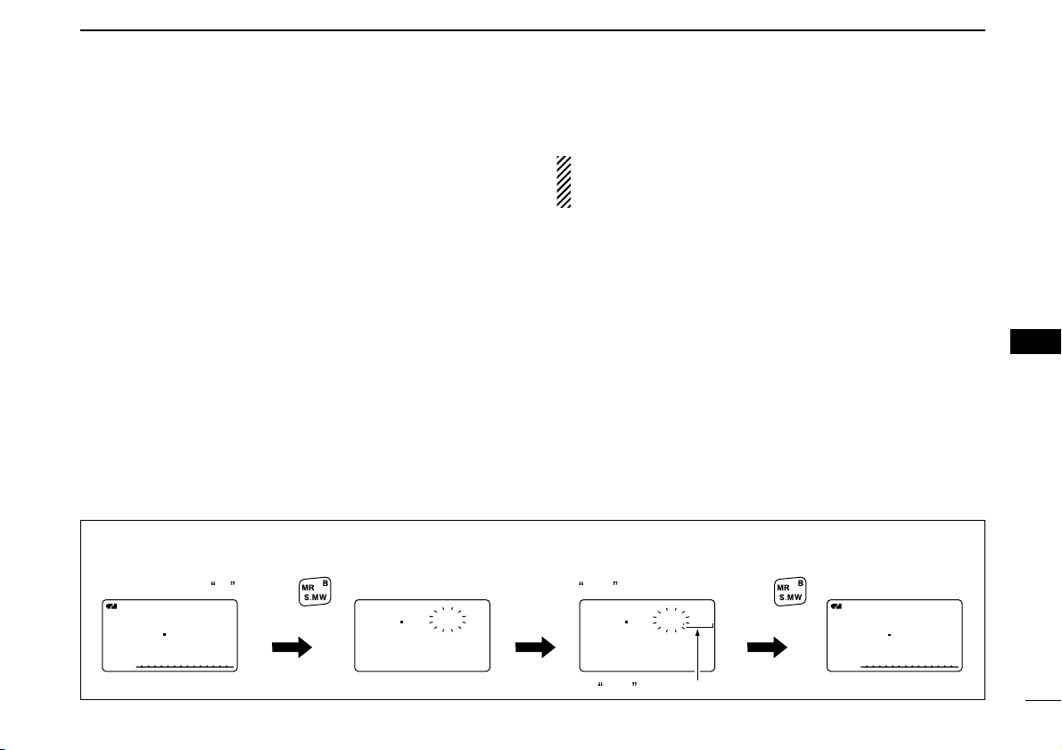
71
8
MEMORY/CALL CHANNELS
1
2
3
4
5
6
7
8
9
10
11
12
13
14
15
16
17
18
19
■ Copying memory/call contents
This function transfers a memory channel’s contents to VFO
(or another memory/call channel). This is useful when searching for signals around a memory channel frequency and for
recalling the offset frequency, subaudible tone frequency etc.
D Memory/call➪VFO
qSelect the memory (call) channel to be copied.
➥ Push [MR] or [CALL] to select memory mode or call
channel mode, then rotate [DIAL] to select the desired
channel.
wPush and hold [S.MW](MR) for 1 sec. to enter select mem-
ory write mode.
• 1 short and 1 long beep sound.
•“µµ” indicator blinks.
eRotate [DIAL] to select “VFO.”
rPush and hold [S.MW](MR) for 1 sec. to write the selected
channel contents to VFO mode.
• Returns to VFO mode automatically.
Holding [S.MW](MR) for 2 sec. at the step w, will also
copy the memory contents to VFO. In this case, the steps
e and r are not necessary.
D Memory/call➪memory/call
qSelect the memory (call) channel to be copied.
➥ Push [MR] or [CALL] to select memory mode or call
channel mode, then rotate [DIAL] to select the desired
memory channel.
wPush and hold [S.MW](MR) for 1 sec. to enter select mem-
ory write mode.
• 1 short and 1 long beep sound.
•“µµ” indicator blinks.
• Do not hold [S.MW](MR) for more than 2 sec. otherwise the
memory contents will be copied to VFO.
eRotate [DIAL] to select the target memory (call) channel.
rPush and hold [S.MW](MR) for 1 sec. again to copy.
A
FMFM
145 870
PSKIPPSKIP
A
µ
FMFM
145 870
011
145 000
FMFM
µ
VFO
145 870
BANKBANK :----:----
MNAME:MNAME:
SKIPSKIP :OFF:OFF
FMFM
r
µ
011
During memory mode,
rotate [DIAL] to select
memory channel 11 .
Rotate [DIAL] to select
VFO .
Push
for 1 sec.
Push
for 1 sec.
VFO is selected.
[EXAMPLE]: Copying memory channel 11 to VFO.
Page 78
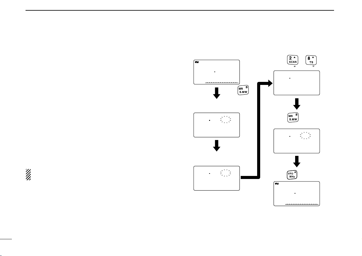
72
8 MEMORY/CALL CHANNELS
■ Memory clearing
Contents of programmed memories can be cleared (blanked),
if desired.
qPush and hold [S.MW](MR) for 1 sec. to enter select mem-
ory write mode.
• 1 short and 1 long beeps sound.
•“µµ” indicator blinks.
• Do not hold [S.MW](MR) for more than 2 sec. otherwise the
memory contents will be copied to VFO.
wRotate [DIAL] to select the desired memory channel to be
cleared.
ePush [∫∫](2) or [√√](8) to select “CLEAR.”
rPush and hold [S.MW](MR) for 1 sec. to clear the contents.
• 3 beeps sound.
• The cleared channel changes to blank channel
• Return to select memory write mode.— “µµ” indicator blinks.
Push [VFO] to exit select memory write mode.
NOTE: Be careful!— the contents of cleared memories
CANNOT be recalled.
146 010
BANKBANK :----:----
MNAME:MNAME:
SKIPSKIP :OFF:OFF
FMFM
r
µ
000
145 000
MNAME:MNAME:
SKIPSKIP :OFF:OFF
CLEARCLEAR
r
µ
005
A
FMFM
145 870
PSKIPPSKIP
145 000
BANKBANK :----:----
MNAME:MNAME:
SKIPSKIP :OFF:OFF
r
µ
005
BANKBANK :----:----
MNAME:MNAME:
SKIPSKIP :OFF:OFF
r
µ
005
A
FMFM
145 870
PSKIPPSKIP
VFO mode
Rotate [DIAL] to select
the desired channel.
Push
for 1 sec. to clear.
Push .
Return to the VFO mode.
Enter select memory
write mode.
Push
for 1 sec.
Push
to select CLEAR .
or
Page 79

73
8
MEMORY/CALL CHANNELS
1
2
3
4
5
6
7
8
9
10
11
12
13
14
15
16
17
18
19
■ Erasing/transferring bank contents
The bank contents of programmed memory channels can be
cleared or reassigned to another memory bank.
INFORMATION: Even if the memory bank contents are
cleared, the memory channel contents still remain programmed.
qSelect the desired bank contents to be transferred or
erased from the bank.
(p. 68)
➥ Push [MR] several times to select memory bank mode.
➥ While pushing [BAND], rotate [DIAL] to select the de-
sired memory bank group.
➥ Rotate [DIAL] to select the bank channel.
wPush [S.MW](MR) for 1 sec. to enter select memory write
mode.
• 1 short and 1 long beeps sound.
• Displays the original memory channel number automatically and
“µµ” indicator blinks.
• Do not hold [S.MW](MR) for more than 2 sec., otherwise the
memory contents will be copied to VFO.
ePush [∫∫](2) or [√√](8) to select “BANK.”
rPush [≈≈](6) or [ΩΩ](4) several times to select the desired
bank group to be transferred.
• Select “– – – –” indication when erasing the contents from the
bank.
tRotate [DIAL] to select the desired bank channel.
• Skip this step when “––––” indication is selected in step r.
yPush [S.MW](MR) for 1 sec. to erase/transfer the bank
contents.
145 600
BANK :---BNAME:
MNAME:
SKIP :OFF
FM
r
µ
025
145 600
BANK :B-11
BNAME:
MNAME:
SKIP :OFF
FM
r
µ
025
To transfer the bank contents
to ch 11 in Bank B.
To erase
[DIAL]
Bank channel is
displayed.
is displayed.
A
µ
FM
433 000
001
A
µ
FM
433 000
C05
[DIAL]
Page 80
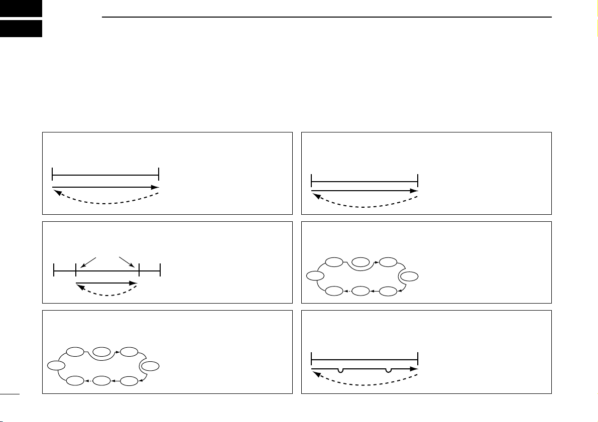
74
SCAN OPERATION
9
■ Scan types
Scanning searches for signals automatically and makes it
easier to locate new stations for contact or listening purposes.
There are 7 scan types and 4 resume conditions to suit your
operating needs.
FULL SCAN (p. 75)
Repeatedly scans all frequencies over the entire band.
Some frequency ranges are
not scanned according to the
frequency coverage of the
transceiver’s version.
495
kHz
999.990
MHz
Scan
Jump
SELECTED BAND SCAN
(p. 75)
Repeatedly scans all frequencies over the entire selected
band.
Band
edge
Band
edge
Scan
Jump
ALL/SELECTED BANK
SCAN (p. 78)
Repeatedly scans all bank
channels or selected bank
channels. The skip scan is
also available.
SKIP
SKIP
A99
A03
A00 A01 A02
A04
A98
A05
FREQUENCY/MEMORY
SKIP FUNCTION (p. 79)
Skips unwanted frequencies
or channels that inconveniently stop scanning. This
function can be turned ON
and OFF by pushing and
holding [SKIP](5) in either
VFO or memory mode.
Band
edge
Band
edge
Scan
SKIP SKIP
Jump
PROGRAMMED SCAN
(p. 75)
Repeatedly scans between
two user-programmed frequencies. Used for checking
for frequencies within a specified range such as repeater
output frequencies, etc.
Band
edge
xxA xxB
Band
edge
Scan edges
Scan
Jump
MEMORY (SKIP) SCAN
(p. 77)
Repeatedly scans memory
channels except those set as
skip channel. Skip channels
can be turned ON and OFF
by pushing and holding
[SKIP](5) in memory mode.
SKIP
SKIP
M 0
M 4
M 1 M 2 M 3
M 5
M 199
M 6
Page 81

75
9
SCAN OPERATION
1
2
3
4
5
6
7
8
9
10
11
12
13
14
15
16
17
18
19
■ Full/band/programmed scan
qPush [VFO] to select VFO mode.
• Select the desired frequency band with [BAND], if desired.
wSet the squelch level.
eWhile pushing and holding [SCAN](2), rotate [DIAL] to se-
lect the desired scanning type.
•“ALL” for full scan; “BAND” for band scan, “PROG-xx (or scan
name if programmed)” for programmed scan (xx= 0 to 24; programmed scan edges numbers are only displayed), “DUP” (appears only when duplex operation is set) for duplex scan.
rTo start the scan, release [SCAN](2).
• Scan pauses when a signal is received.
• Rotate [DIAL] to change the scanning direction, or resumes
manually.
• Push [VFO] to stop the scan.
About the scanning steps: The selected tuning step in
each frequency band (in VFO mode) is used during scan.
Duplex scan function: Repeatedly scans two frequencies
(transmission/reception) during duplex scan operation.
FMFM
A
148 800
FMFM
A
P SKIPSKIP P SKIPSKIP
P01P01
148 800
• During full/band scan • During programmed scan
FMFM
A
146 010
SCAN:ALL
FM
A
148 800
SCAN:BAND
FM
A
148 800
SCAN:PROG-01
P SKIPSKIP
P SKIPSKIP
P SKIPSKIP
• Full scan selection
• Programmed scan selection
• Band scan selection
Selectable between “ 00” to “24”
if programmed.
[DIAL]
FMFM
A
148 800
P SKIPSKIP
P01P01
FMFM
A
148 800
P SKIPSKIP
SCAN:SCANNAME
Scan name
Scan name is not displayed during a programmed scan.
Scan edge number
Scan name selection
Page 82

76
9 SCAN OPERATION
■ Scan edges programming
Scan edges can be programmed in the same manner as
memory channels. Scan edges are programmed into scan
edges, 00A/00B to 24A/24B, in memory channels.
qPush [VFO] to select VFO mode.
wSet the desired frequency:
➥ Select the desired band with [BAND].
➥ Set the desired frequency with [DIAL].
➥ Set other data
(e.g. offset frequency, duplex direction, tone
squelch, etc.), if desired.
ePush and hold [S.MW](MR) for 1 sec. to enter the select
memory write mode.
• 1 short and 1 long beeps sound.
•“µµ” indicator blinks.
rRotate [DIAL] to select the desired programmed scan
edge channel from 00A to 24A.
tPush and hold [S.MW](MR) for 1 sec.
• 3 beeps sound.
• The other scan edge channel “B,” 00B to 24B, is automatically
selected when continuing to push [S.MW](MR) after programming.
yTo program a frequency for the other pair of scan edges,
00B to 24B, repeat steps w and r.
• If the same frequency is programmed into a pair of scan edges,
programmed scan will not function.
[DIAL]
[EXAMPLE]: Programming 145.300 MHz into scan edges 03A.
A
FMFM
145 300
P SKIPSKIP
A
FMFM
145 300
P SKIPSKIP
03A
A
FMFM
145 300
P SKIPSKIP
146 010
BANKBANK :----:----
MNAME:MNAME:
SKIPSKIP :OFF:OFF
FMFM
r
µ
001
BANKBANK :----:----
MNAME:MNAME:
SNAME:SNAME:
FMFM
r
µ
03A
Push for 1 sec.
Rotate [DIAL]
Push for 1 sec.
Page 83

77
9
SCAN OPERATION
1
2
3
4
5
6
7
8
9
10
11
12
13
14
15
16
17
18
19
■ Memory scan
IMPORTANT!: To perform memory scan, 2 or more mem-
ory channels MUST be programmed, otherwise the scan
will not start.
qPush [MR] to select memory mode.
wSet the squelch level.
eWhile pushing and holding [SCAN](2), rotate [DIAL] to se-
lect the desired scanning type.
•“ALL” for full memory scan; “BAND” for band memory scan,
“MODE” for mode scan, “DUP” (appears only when duplex oper-
ation is set) for duplex scan.
rRelease [SCAN](2) to start the selected scan.
• Scan pauses when a signal is received.
• Rotate [DIAL] to change the scanning direction, or resumes
manually.
tTo stop the scan, push [VFO].
Band memory scan function: Repeatedly scans all
memory channels programmed with any frequencies of the
band programmed in the memory channel selected for
scanning.
Mode scan function: Repeatedly scans all memory channels in which the same operating mode as the selected
memory channel has been programmed.
Duplex scan function: Repeatedly scans two frequencies
(transmission/reception) during duplex scan operation.
FM
A
µ
012
148 800
• During memory scan
FMFM
A
146 010
µ
088088
SCAN:ALL
FM
A
148 800
µ
088088
SCAN:BAND
FM
A
148 800
µ
088088
SCAN:MODE
P SKIPSKIP
P SKIPSKIP
P SKIPSKIP
• All memory scan selection
• Mode scan selection
• Band memory scan selection
[DIAL]
Page 84

78
9 SCAN OPERATION
■ Memory bank scan
IMPORTANT!: To perform memory bank scan, 2 or more
bank channels MUST be programmed, otherwise the scan
will not start.
qPush [S.MW](MR) several times to select memory bank
mode.
wSet the squelch level.
eWhile pushing and holding [SCAN](2), rotate [DIAL] to se-
lect the desired scanning type.
•“ALL” for all bank scan; “BANK-LINK” for bank link scan or
“BANK-x” for bank scan (x= A to Z; programmed bank groups
are only displayed.), “DUP” (appears only when duplex operation is set) for duplex scan.
rRelease [SCAN](2) to start the selected scan.
• Scan pauses when a signal is received.
• Rotate [DIAL] to change the scanning direction, or resumes
manually.
tTo stop the scan, push [VFO].
The bank-link setting can be changed in scan set mode.
See page 97 for details.
Duplex scan function: Repeatedly scans two frequencies
(transmission/reception) during duplex scan operation.
FM
A
µ
888
148 800
• During all bank/bank link scan • During bank scan
FM
A
µ
A88
148 800
FMFM
A
146 010
µ
A01A01
SCAN:ALL
FM
A
148 800
µ
A01A01
SCAN:BANK-LINK
FM
A
148 800
µ
A01A01
SCAN:BANK-A
P SKIPSKIP
P SKIPSKIP
P SKIPSKIP
• All bank scan selection
• Bank scan selection
• Bank link scan selection
Selectable between “A” to “Z”
if programmed.
[DIAL]
Page 85

79
9
SCAN OPERATION
1
2
3
4
5
6
7
8
9
10
11
12
13
14
15
16
17
18
19
■ Skip channel/frequency setting
Memory channels can be set to be skipped for memory skip
scan. In addition, memory channels can be set to be skipped
for both memory skip scan and frequency skip scan. These
are useful to speed up the scan rate.
qSelect a memory channel:
➥ Push push [MR] to select memory mode.
➥ Rotate [DIAL] to select the desired channel to be a skip
channel/frequency.
wPush and hold [S.MW](MR) for 1 sec. to enter select mem-
ory write mode.
ePush [∫∫](2) or [√√](8) several times to select “SKIP.”
rRotate [DIAL] to select the skip condition from “SKIP,”
“P SKIP” or “OFF” for the selected channel.
• P SKIP: The channel is skipped during memory/bank scan and
the programmed frequency is skipped during VFO scan,
such as programmed scan.
• SKIP : The channel is skipped during memory or bank scan.
• OFF : The channel is scanned during any scan.
(Continue to the next page.)
146 010
BANK :----
MNAME:
SKIP :OFF
FMFM
r
µ
012
146 010
MNAME:
SKIP :OFF
CLEAR
FMFM
r
µ
012
or
several times.
Push
FMFM
A
µ
020020
145 870
[DIAL]
Page 86

80
9 SCAN OPERATION
tPush and hold [S.MW](MR) for 1 sec. to store the skip con-
dition into the memory.
•“SKIP” or “P SKIP” indicator appears, according to the skip se-
lection in the step r.
✔
CONVENIENT!
The the skip setting can be set with the following operation.
qSelect the desired memory channel to be set as a skip
channel/frequency.
w
While pushing [SKIP](5), rotate [DIAL] to select the skip condition from “P SKIP,” “SKIP” and “OFF (no indication).”
✔
CONVENIENT!
During VFO scanning, such as programmed scan, the skip
setting can be programmed into the highest blank memory
channel which is automatically selected with the following operation.
qStart the VFO scan.
➥ Push
[VFO] to select VFO mode.
• Select the desired frequency band with [BAND], if desired.
➥ Set the squelch level.
➥ While pushing and holding [SCAN](2), rotate [DIAL] to
select the desired scanning type.
•“ALL” for full scan; “BAND” for band scan, “PROG-xx (or scan
name if programmed)” for programmed scan (xx= 0 to 24;
programmed scan edges numbers are only displayed), “DUP”
for duplex scan.
➥ To start the scan, release [SCAN](2).
• Scan pauses when a signal is received.
• Rotate [DIAL] to change the scanning direction, or resumes
manually.
wWhen scan pauses and you want to set the paused fre-
quency as a skip frequency.
➥ Push and hold [SKIP](5) for 1 sec. to store the paused
frequency into the highest blank memory channel.
• While pushing and holding [SKIP](5), rotate [DIAL] to select a
skip condition from “SKIP,” “P SKIP” and “OFF.”
• While pushing and holding [SKIP](5), scan pauses; and after
writing the frequency, scan resumes.
FMFM
A
µ
SKIPSKIP
033033
145 700
FMFM
A
µ
P SKIPSKIP
033033
145 700
• Skip channel setting
• Program skip setting
“SKIP” appears
“P SKIP” appears
Page 87

■ Scan resume condition
DD
Scan pause timer
The scan pauses when receiving signals according to the
scan pause time. It can be set from 2 to 20 sec. or unlimited.
qEnter “PAUSE” in scan set mode.
(p. 96)
w Rotate [DIAL]†to set the desired scan pausing time from
2–20 sec. (2 sec. steps) or “HOLD.”
•“2SEC”–“20SEC”: Scan pauses for 2–20 sec. while receiving a
signal.
•“HOLD” : Scan pauses on a received a signal until it
disappears.
e Push [ï](5) (or [
ΩΩ
](4)) to return to scan set mode.
r [MENU/LOCK] to return to frequency indication.
DD
Scan resume timer
The scan restarts after the signal disappears according to the
resume time. It can be set from 0–5 sec. or unlimited.
qEnter “RESUME” in scan set mode.
(p. 96)
w Rotate [DIAL]†to set the desired scan resume time from
0–5 sec. (1 sec. steps) and “HOLD.”
•“0SEC” : Scan restarts immediately after the signal
disappears.
•“1SEC”–“5SEC” : Scan restarts 1–5 sec. after the signal disap-
pears.
•“HOLD” : Scan restarts by rotating [DIAL] only.
e Push [ï](5) (or [
ΩΩ
](4)) to return to scan set mode.
r [MENU/LOCK] to return to frequency indication.
Scan resume timer must be set shorter than the scan
pause timer, otherwise this timer does not activate.
• Resume timer setting
2SEC2SEC
4SEC4SEC
3SEC3SEC
1SEC1SEC
5SEC5SEC
RESUME TIMER
r
MENU screen ➪ SCAN ➪ RESUME
(Push [MENU/LOCK]) (Rotate [DIAL]†, then push [ï](5)†.)
10SEC10SEC
6SEC6SEC
8SEC8SEC
4SEC4SEC
12SEC12SEC
PAUSE TIMER
r
• Pause timer setting
MENU screen ➪ SCAN ➪ PAUSE
(Push [MENU/LOCK]) (Rotate [DIAL]†, then push [ï](5)†.)
81
9
SCAN OPERATION
1
2
3
4
5
6
7
8
9
10
11
12
13
14
15
16
17
18
19
†
[DIAL] ↔ [∫∫](2)/[√√](8) [ï](5) ↔ [≈≈](6)
Page 88

82
PRIORITY WATCH
10
■ Priority watch types
Priority watch checks for signals on the frequency every
5 sec. while operating on a VFO frequency or scanning. The
transceiver has 3 priority watch types to suit your needs.
The watch resumes according to the selected scan resume
condition. See page 81 for details.
NOTE: If the pocket beep function is activated, the transceiver automatically selects the tone squelch function
when priority watch starts.
DD
About priority beep function
When receiving a signal on the priority frequency, you can be
alerted with beeps and a blink “S.” This function can be
activated when setting the priority watch function ON.
MEMORY/CALL CHANNEL WATCH
While operating on a VFO frequency, priority watch checks for
a signal on the selected every 5
sec.
• A memory channel with skip information can be watched.
MEMORY SCAN WATCH
While operating on a VFO frequency, priority watch checks for
signals on each memory channel in sequence.
• The memory skip function and/or
memory bank scan is useful to
speed up the scan.
VFO SCAN WATCH
While scanning in VFO mode,
priority watch checks for signals
on the selected every 5 sec.
5 sec.
VFO
frequency
5 sec.
VFO
frequency
5 sec.
VFO
scan
SKIP
Memory
(Call)
channel
Mch 000
Mch 001
Mch 001
Mch 999
Memory
(Call)
channel
Page 89

■ Priority watch operation
DD
Memory/call channel and memory scan watch
qSelect VFO mode; then, set an operating frequency.
wSet the watching channel(s).
For memory channel watch:
Select the desired memory channel.
For call channel watch:
Select the desired call channel.
For memory scan watch:
Select memory mode, or the desired bank group; then,
push and hold [SCAN](2) for 1 sec. to start memory/bank
scan.
eEnter “PRIO WATCH” in scan set mode.
(p. 96)
r Rotate [DIAL]†to select “ON.”
• Select “BELL” if the priority beep function is desired.
t Push [MENU/LOCK] to exit scan set mode and start the
watch.
•“PRIO” indicator appears.
• The transceiver checks the memory/bank channel(s) or call
channel every 5 sec.
• The watch resumes according to the selected scan resume condition. (p. 81)
y Push [VFO] to cancel the watch.
• During priority watch
Monitors VFO frequency
for 5 sec.
Pauses on a memory or
call channel when a signal is received.
• During priority watch with priority beep
Emits beep and blinks “S” indicator when a signal is re-
ceived on a memory or call channel.
PRIOPRIOFMFM
A
145 180
µ
035035
PRIOPRIOFMFM
A
433 260
P SKIPSKIP
PRIOPRIOFMFM
A
145 180
µ
035035
PRIOPRIOFMFM
A
433 260
P SKIPSKIP
MENU screen ➪ SCAN ➪ PRIO WATCH
(Push [MENU/LOCK]) (Rotate [DIAL]†, then push [ï](5)†.)
Although [DIAL] and [ï](5) are used for description in this
section, [∫∫](2)/[√√](8) and [≈≈](6) are available instead of
[DIAL] and [ï](5).
83
10
PRIORITY WATCH
1
2
3
4
5
6
7
8
9
10
11
12
13
14
15
16
17
18
19
†
[DIAL] ↔ [∫∫](2)/[√√](8) [ï](5) ↔ [≈≈](6)
Page 90

84
10 PRIORITY WATCH
DD
VFO scan watch
qSet the watching channel(s).
For memory channel watch:
Select the desired memory channel.
For call channel watch:
Select the desired call channel.
For memory scan watch:
Select memory mode, or the desired bank group; then,
push and hold [SCAN](2) for 1 sec. to start memory/bank
scan.
wEnter “PRIO WATCH” in scan set mode.
(p. 96)
e Rotate [DIAL]†to select “ON.”
• Select “BELL” if the priority beep function is desired.
r Push [VFO] to exit scan set mode and start the watch.
•“PRIO” indicator appears.
tPush and hold [SCAN](2) for 1 sec. to enter scan type se-
lection condition.
yRotate [DIAL] to select the desired scan type from “ALL,”
“BAND” and “PROG-xx
(xx= 0–24),” “DUP.”
uRelease [SCAN](2) to start the VFO scan watch.
• The transceiver checks the memory/bank channel(s) or call
channel every 5 sec.
• The watch resumes according to the selected scan resume condition. (p. 81)
i Push [VFO] to cancel the watch.
• During priority watch
Searches VFO frequencies
for 5 sec.
Pauses on a memory or
call channel when a signal is received.
• During priority watch with priority beep
Emits beep and blinks “S” indicator when a signal is re-
ceived on a memory or call channel.
PRIOPRIOFMFM
A
145 000
µ
000000
PRIOPRIOFMFM
A
888 800
P SKIPSKIP
PRIOPRIOFMFM
A
145 000
µ
000000
PRIOPRIOFMFM
A
888 800
P SKIPSKIP
MENU screen ➪ SCAN ➪ PRIO WATCH
(Push [MENU/LOCK]) (Rotate [DIAL]†, then push [ï](5)†.)
†
[DIAL] ↔ [∫∫](2)/[√√](8) [ï](5) ↔ [≈≈](6)
Page 91

85
11
MENU SCREEN OPERATION
1
2
3
4
5
6
7
8
9
10
11
12
13
14
15
16
17
18
19
■ General
MENU screen is used for programming infrequently changed
values or conditions of functions.
DD
Entering MENU screen and operation
e.g.) Set “AUTO power OFF” to 30 minutes.
qPush [MENU/LOCK] to enter MENU screen.
wRotate [DIAL]
†
to select the desired menu group, then
push [ï](5)
†
.
eRotate [DIAL]
†
to select the desired item, then push
[ï](5)
†
.
rRotate [DIAL]
†
to select the desired value or condition,
then push [ï](5) to return to the setting item selection
mode.
tPush [MENU/LOCK] to return to frequency indication, re-
peat steps w to r to set another items.
[DIAL]
OFFOFF
30MIN30MIN
60MIN60MIN
90MIN90MIN
120MIN120MIN
AUTO POWER OFF
r
OFFOFF
30MIN30MIN
60MIN60MIN
90MIN90MIN
120MIN120MIN
AUTO POWER OFF
r
AP OFFAP OFF
POWER SAVEPOWER SAVE
ATTENUATORATTENUATOR
MONITORMONITOR
DIAL SPEEDDIAL SPEED
SET MODE
r
• Setting items
appear.
SET MODESET MODE
SCANSCAN
DUP/TONE...DUP/TONE...
DISPLAYDISPLAY
SOUNDSSOUNDS
***** MENU *****
r
• MENU groups
appear.
†
[DIAL] ↔ [∫∫](2)/[√√](8) [ï](5) ↔ [≈≈](6)
Page 92

86
11 MENU SCREEN OPERATION
■ MENU screen indication for
B band*
While B band is selected, MENU screen shows following indication.
*The optional UT-121 is required for IC-91A.
■ Menu list
†
Refer to the chapter 7 for details.
■ Items list
DD
Set mode
AUTO POWER OFF
POWER SAVE
ATTENUATOR
MONITOR
DIAL SPEED-UP
AUTO REPEATER
MIC SIMPLE MODE
ITEMS
p. 88
p. 88
p. 88
p. 89
p. 89
p. 89
p. 90
REF.
WEATHER ALERT
AUTO POWER ON
LOCK
PTT LOCK
BUSY LOCKOUT
TIME-OUT TIMER
ACTIVE BAND
ITEMS
p. 90
p. 90
p. 90
p. 91
p. 91
p. 91
p. 91
REF.
pgs. 92–95
pgs. 96, 97
pgs. 97–99
pgs. 99–101
p. 102
—
—
—
—
pgs. 88–91
CALL SIGN
†
RX CALL SIGN
†
MESSAGE/POSITION
†
DV VOICE MEMO
†
SET MODE
MENU REF.
DV SET MODE
SCAN
DUP/TONE…
DISPLAY
SOUNDS
MENU REF.
RX CALL SRX CALL S
MESSAGE/POSMESSAGE/POS
DV VOICE MDV VOICE M
SET MODESET MODE
DV SET MODEDV SET MODE
***** MENU ********** MENU *****
r
MENU screen indication for B band.
Page 93

87
11
MENU SCREEN OPERATION
1
2
3
4
5
6
7
8
9
10
11
12
13
14
15
16
17
18
19
DD
DV set mode
Available for B band of IC-91AD, or if the UT-121 is installed in the IC91A.
DD
Scan set mode
‡
Not available during the TV band or weather channel mode selection.
DD
DUP/TONE set mode
Not available for the TV and weather channel mode.
DD
DISPLAY set mode
*1Available for B band of IC-91AD, or UT-121 is installed IC-91Aonly.
*2Available for B band of IC-91AD, or if the UT-121 is installed in the
IC-91A.
DD
SOUNDS set mode
*1Available for B band of IC-91AD, or if the UT-121 is installed in the
IC-91A.
BEEP LEVEL
KEY-TOUCH BEEP
SCAN STOP BEEP
ITEMS
p. 102
p. 102
p. 102
REF.
SCOPE AF OUTPUT
VOLUME SELECT
STANDBY BEEP*
1
ITEMS
p. 102
p. 102
p. 103
REF.
BACKLIGHT
BUSY LED
LCD CONTRAST
RX CALL SIGN*
1
TX CALL SIGN*
1
RX MESSAGE*
1
ITEMS
p. 99
p. 99
p. 100
p. 100
p. 100
p. 100
REF.
SCAN NAME
OPENING LOGO
OPENING CALL S*
2
FONT SIZE
ITEMS
p. 101
p. 101
p. 101
p. 101
REF.
OFFSET FREQ
REPEATER TONE
CTCSS TONE
ITEMS
p. 97
p. 97
p. 98
REF.
DTCS CODE
DTCS POLARITY
DTMF SPEED
ITEMS
p. 98
p. 99
p. 99
REF.
PRIO WATCH
‡
PAUSE TIMER
RESUME TIMER
ITEMS
p. 96
p. 96
p. 96
REF.
BANK LINK
➥ BANK-A
ITEMS
p. 97
p. 97
REF.
AUTO REPLY
DIGITAL CODE
DV DATA TX
DIGITAL MONITOR
DIGITAL RPT SET
RXCALL WRITE
RXRPT WRITE
ITEMS
p. 92
p. 92
p. 92
p. 93
p. 93
p. 93
p. 93
REF.
GPS MODE
➥ GPS SENTENCE
➥ RMC SENTENCE
GGA SENTENCE
GLL SENTENCE
GSA SENTENCE
VTG SENTENCE
GPS AUTO TX
DV AUTO DETECT
EDIT RECORD
ITEMS
p. 94
p. 94
p. 94
p. 94
p. 94
p. 94
p. 94
p. 95
p. 95
p. 95
REF.
Page 94

88
11 MENU SCREEN OPERATION
■ Set mode items
DD
Auto power OFF
The transceiver can be set to automatically turn OFF after a
specified time period with a beep when no key operations are
performed.
30 min., 60 min, 90 min, 120 min and OFF
(default) can be
specified. The specified time period is retained even when the
transceiver is turned OFF by the auto power OFF function. To
cancel the function, select “OFF” in this item.
DD
Power save
The power save function reduces the current drain to conserve battery power. This power save function can be turned
OFF, if desired, by turning power ON and OFF.
In the default setting
(“AUTO” selection), the power save func-
tion is activated in a 1:1
(150 msec.: 150 msec.) ratio when no
signal is received for 5 sec. The ratio becomes 1:4
(150 msec.:
600 msec.) when no signal is received for another 60 sec.
Then the ratio becomes 1:8
(150 msec.: 1200 msec.) when no
signal is received for another more 60 sec.
DD
Attenuator
The attenuator prevents distortion of a desired signal by very
strong RF signals near the desired frequency or when very
strong electric fields, such as from a broadcasting station, are
present at your location.
Select the attenuator function ON and OFF
(default).
OFFOFF
ONON
ATTENUATOR
r
ONON
OFFOFF
ATTENUATOR
r
AUTOAUTO
OFFOFF
POWER SAVE
r
OFFOFF
AUTOAUTO
POWER SAVE
r
OFFOFF
30MIN30MIN
60MIN60MIN
90MIN90MIN
120MIN120MIN
AUTO POWER OFFAUTO POWER OFF
r
30MIN30MIN
OFFOFF
60MIN60MIN
90MIN90MIN
120MIN120MIN
AUTO POWER OFF
r
Page 95

89
11
MENU SCREEN OPERATION
1
2
3
4
5
6
7
8
9
10
11
12
13
14
15
16
17
18
19
DD
Monitor key action
The monitor key, [SQL] , can be set as a ‘sticky’ key. When
set to the sticky condition, each push of [SQL] toggles the
monitor function ON and OFF.
• PUSH: Pushing and holding [SQL] to monitor the fre-
quency. (default)
• HOLD : Push [SQL] momentarily to monitor the frequency
and push momentarily again to cancel it.
DD
Dial speed acceleration
The dial speed acceleration automatically speeds up the tuning dial speed when rotating [DIAL] rapidly.
• OFF : The dial speed acceleration is turned OFF.
• ON : The dial speed acceleration is tuned ON.
(default)
DD
Auto repeater
The auto repeater function automatically turns ON or OFF the
duplex operation and tone encoder. The offset and repeater
tone is not changed by the auto repeater function. Reset
these frequencies, if necessary.
U.S.A. version:
• OFF : The auto repeater function is turned OFF.
• RPT1 : Activates for duplex only. (default)
• RPT2 : Activates for duplex and tone.
Korean version:
• OFF : Deactivates the function.
• ON : Activates duplex and tone. (default)
ONON
OFFOFF
AUTO REPEATER
r
OFFOFF
ONON
AUTO REPEATER
r
RPT1RPT1
OFFOFF
RPT2RPT2
AUTO REPEATER
r
OFFOFF
RPT1RPT1
RPT2RPT2
AUTO REPEATER
r
U.S.A./KOREAN versions only
ONON
OFFOFF
DIAL SPEED-UP
r
OFFOFF
ONON
DIAL SPEED-UP
r
PUSHPUSH
HOLDHOLD
MONITOR
r
HOLDHOLD
PUSHPUSH
MONITOR
r
Page 96

90
11 MENU SCREEN OPERATION
DD
Microphone simple mode
Microphone simple mode is used to change the function assignments for keys on the optional HM-75A
REMOTE CONTROL
SPEAKER
-
MICROPHONE
. (pgs. 122, 124)
• SIMPLE
• NORM-1 (default)
• NORM-2
DD
Weather alert function
Turns weather alert function ON and OFF. (p. 114)
(default: OFF)
DD
Auto power ON
Auto power ON function turns the transceiver power ON automatically after passing the set time period from power OFF.
Select the desired time period within 30 minutes to 24 hours
in 30 minutes steps and OFF.
(default: OFF)
DD
Key lock Type
While the key lock function is ON, [PWR], [PTT], [SQL],
[VOL] and [MENU](
Lock function only) can still be accessed.
Accessible keys can be set to 1 of 4 groups.
• NORMAL : [PWR], [PTT], [SQL], [VOL] and [MENU]
(Lock function only) accessible. (default)
• NO SQL : [PWR], [PTT], [SQL], and [MENU] (Lock func-
tion only) are accessible.
• NO VOL : [PWR], [PTT], [VOL], and [MENU]
(Lock func-
tion only) are accessible.
• ALL : [PWR], [PTT] and [MENU]
(Lock function only)
are accessible.
NORMALNORMAL
NO SQLNO SQL
NO VOLNO VOL
ALLALL
LOCK
r
NORMALNORMAL
NO SQLNO SQL
NO VOLNO VOL
ALLALL
LOCK
r
OFFOFF
AUTO POWER ON
24:0024:00
AUTO POWER ON
OFFOFF
ONON
WEATHER ALERT WEATHER ALERT
r
OFFOFF
ONON
WEATHER ALERT
r
U.S.A. version only
NORM-1NORM-1
SIMPLESIMPLE
NORM-2NORM-2
MIC SIMPLE MODEMIC SIMPLE MODE
r
SIMPLESIMPLE
NORM-1NORM-1
NORM-2NORM-2
MIC SIMPLE MODE
r
Page 97

91
11
MENU SCREEN OPERATION
1
2
3
4
5
6
7
8
9
10
11
12
13
14
15
16
17
18
19
DD
PTT lock
Turns the PTT lock function ON and OFF.
Transmission with [PTT] is inhibited when ON is selected to
prevent accidental transmission, etc. (default: OFF)
DD
Busy lockout
Turns the busy lockout function ON and OFF.
This function inhibits transmission while receiving a signal or
when the squelch is open. (default: OFF)
DD
Time-out timer
To prevent accidental prolonged transmission, etc., the transceiver has a time-out timer. This function cuts a transmission
OFF after 1, 3, 5 or 10 min. of continuous transmission. This
timer can be cancelled.
• OFF : The time-out timer is turned OFF. (default)
• 1 to 10 MIN : The transmission is cut OFF after the set
period elapses.
DD
Active band
Allows continuous frequency selection of the operating frequency across all bands.
• SINGLE : A single operating frequency can be se-
lected within the current band. Push
[BAND] for band selection in this case.
• ALL : The operating frequency can be selected
continuously. (default)
ALLALL
SINGLESINGLE
ACTIVE BAND
r
ALLALL
SINGLESINGLE
ACTIVE BAND
r
OFFOFF
1MIN1MIN
3MIN3MIN
5MIN5MIN
10MIN10MIN
TIME-OUT TIMER
r
OFFOFF
1MIN1MIN
3MIN3MIN
5MIN5MIN
10MIN10MIN
TIME-OUT TIMER
r
OFFOFF
ONON
BUSY LOCKOUT
r
OFFOFF
ONON
BUSY LOCKOUT
r
OFFOFF
ONON
PTT LOCK
r
OFFOFF
ONON
PTT LOCK
r
Page 98

92
11 MENU SCREEN OPERATION
■ DV set mode items
The following items are selectable by the IC-91AD or optional
UT-121 is installed into the IC-91A.
DD
Auto reply
This function replies to an individual station call even you are
away from the transceiver.
After a manual transmission (pushing [PTT]), the Auto Reply
setting returns to OFF automatically.
• OFF : No reply is performed even a call is received.
(default)
• ON : Sets caller’s call sign and reply to the call with
the set own call sign automatically.
• VOICE : Sets caller’s call sign and reply to the call with
the recorded audio in REPLY VOICE memory of
DV VOICE MEMO.
NOTE: When “ON” or “VOICE” is set to the auto reply
function, the power save function
(p. 88) is turned OFF au-
tomatically to receive call sign signal properly.
DD
Digital code
Sets the desired digital code for digital code squelch operation. Total of 100 codes (00–99) are available. (default: 00)
DD
DV data TX
During low-speed data operation, auto data transmission
function is available. This function transmits when data has
been input from PC via the [DATA] jack.
(default: PTT)
PTTPTT
AUTOAUTO
DV DATA TX
PTTPTT
AUTOAUTO
DV DATA TX
r
r
0000
DIGITAL CODE
9999
DIGITAL CODE
OFFOFF
ONON
VOICEVOICE
AUTO REPLYAUTO REPLY
r
OFFOFF
ONON
VOICEVOICE
AUTO REPLY
r
Page 99

93
11
MENU SCREEN OPERATION
1
2
3
4
5
6
7
8
9
10
11
12
13
14
15
16
17
18
19
DD
Digital monitor
Sets the desired monitoring mode during digital mode operation from “Auto,” “Digital” and “Analog.”
• AUTO : The transceiver sets monitoring mode to FM
and DV according to the received signal.
(de-
fault)
• DIGITAL : Monitors in DV mode.
• ANALOG : Monitors in FM mode.
DD
Digital repeater setting
When accessing a digital repeater with a call sign different
than is programmed, the repeater call sign can be stored into
“RPT1” and/or “RPT2” automatically by reading the repeater’s
transmission. The stored repeater’s call sign can be re-called
when selecting the repeater call sign. (default: ON)
DD
RX call sign auto write
When an individual station call is received, the calling station
call sign can be automatically set in “UR.” (default: OFF)
DD
Repeater call sign auto write
When accessing a repeater with a call sign different than is
programmed, the repeater call sign can be set into “RPT1”
and/or “RPT2” automatically by reading the repeater’s transmission. (default: OFF)
The transceiver sets the received repeater call sign for operation. Therefore, when a different call sign is set for operation, the previously set repeater call sign will be lost.
OFFOFF
AUTOAUTO
RXRPT WRITE
r
OFFOFF
AUTOAUTO
RXRPT WRITE
r
OFFOFF
AUTOAUTO
RXCALL WRITE
r
OFFOFF
AUTOAUTO
RXCALL WRITE
r
ONON
OFFOFF
DIGITAL RPT SET
r
ONON
OFFOFF
DIGITAL RPT SET
r
AUTOAUTO
DIGITALDIGITAL
ANALOGANALOG
DIGITAL MONITOR
r
AUTOAUTO
DIGITALDIGITAL
ANALOGANALOG
DIGITAL MONITOR
r
Page 100

94
11 MENU SCREEN OPERATION
DD
GPS mode
Sets GPS mode operation ON and OFF.
When the position information is received from a connected
GPS receiver and the GPS Auto TX Timer setting (p. 95) is
set to a specific time, the transceiver automatically transmits
with the current position and message at every setting interval.
(default: OFF)
• Sentence formatter setting
q Select “ON” in GPS mode item, then push [ï](5)†to enter
the sentence formatter selection.
w Rotate [DIAL]
†
to select the desired sentence formatter.
• RMC, GGA, GLL, GSA and VTG are selectable.
e Push [ï](5)†to enter the desired sentence formatter se-
lection.
r Rotate [DIAL]
†
to select the setting.
t Rotate [DIAL]†to select next sentence and repeat steps
w to r, or push [MENU/LOCK] to return to frequency in-
dication.
• Only three sentence formatters can be activated at same time.
OFFOFF
ONON
RMC SENTENCE
r
OFFOFF
ONON
RMC SENTENCE
r
RMC:OFFRMC:OFF
GGA:ONGGA:ON
GLL:OFFGLL:OFF
GSA:OFFGSA:OFF
VTG:OFFVTG:OFF
GPS SENTENCE
r
RMC:OFFRMC:OFF
GGA:ONGGA:ON
GLL:OFFGLL:OFF
GSA:OFFGSA:OFF
VTG:OFFVTG:OFF
GPS SENTENCE
r
OFFOFF
ONON
:SENTENCE
GPS MODE
r
:SENTENCE
OFFOFF
ONON
GPS MODE
r
†
[DIAL] ↔ [∫∫](2)/[√√](8) [ï](5) ↔ [≈≈](6)
 Loading...