

Icom IC-7851 Instruction Manual

THE TRANSCEIVER
i7851
Instruction Manual
A-7205H-1EX-0a
Printed in Japan
© 2015 Icom Inc.

i
FOREWORD
Thank you for choosing the IC-7851. The IC-7851 has many built-in high technology circuitry and unique functions, such as the Dualwatch on the Main and
Sub bands, a high speed spectrum scope scan, a high-resolution waterfall
screen, and many other outstanding features.
The internal frequency signals in a radio utilizing a PLL are not always sufficiently pure. This results in a considerable number of unwanted spurious
components, called phase noise, in its frequency spectrum. We focused intensively in drastically reducing the phase noise of LO (Local Oscillator) because
the phase noise degrades the interference rejection and noise characteristics
of the receiver. As a result, we succeeded in developing an LO with high purity outputs so that results in an RMDR (Reciprocal Mixing Dynamic Range)
of 110 dB with newly developed 1.2 kHz Optimum Roofing Filter. Currently no
competitors have been able to achieve this extremely high result performance.
We believe we would not have been able to exceed the standard specifications without our full focus on LO purity.
In addition, Icom that has chosen to base the IC-7851 on an up-conversion,
double super-heterodyne receiver design, which has many advantages over
traditional receiver designs.
We are proud to have developed the IC-7851 for your amateur radio activities,
and hope it brings you years of enjoyable operation.
Please read this instruction manual thoroughly before using the IC-7851.
ii
IMPORTANT
READ THIS INSTRUCTION MANUAL CAREFULLY before at-
tempting to operate the transceiver.
SAVE THIS INSTRUCTION MANUAL. This manual contains important
safety and operating instructions for the IC-7851.
EXPLICIT DEFINITIONS
WORD DEFINITION
R DANGER!
Personal death, serious injury or an explosion may occur.
R WARNING!
Personal injury, fire hazard or electric shock may occur.
CAUTION
Equipment damage may occur.
NOTE
Recommended for optimum use. No risk of personal injury, fire or electric shock.
TRADEMARKS
Icom, Icom Inc. and the Icom logo are registered trademarks of Icom
Incorporated (Japan) in Japan, the United States, the United Kingdom,
Germany, France, Spain, Russia and/or other countries.
This product includes “zlib” open source software, and is licensed according to the open source software license.
This product includes “libpng” open source software, and is licensed according to the open source software license.
Refer to the Text files in the License folder of included CD for information on the open source software being used
by this product.
DISPOSAL
The crossed-out wheeled-bin symbol on your product, literature, or packaging reminds you that in
the European Union, all electrical and electronic products, batteries, and accumulators
(rechargeable batteries) must be taken to designated collection locations at the end of their working life. Do not dispose of these products as unsorted municipal waste.
Dispose of them according to the laws in your area.

iii
PRECAUTIONS
R DANGER HIGH RF VOLTAGE! NEVER
attach an antenna or internal antenna connector
during transmission. This may result in an electrical
shock or burn.
R WARNING! NEVER operate the transceiver
with a headset or other audio accessories at high
volume levels. The continuous high volume operation
may cause a ringing in your ears. If you experience
the ringing, reduce the volume level or discontinue
use.
R WARNING! NEVER operate or touch the
transceiver with wet hands. This may result in an electric shock or damage to the transceiver.
R WARNING! NEVER let metal, wire or other ob-
jects protrude into the transceiver or into connectors
on the rear panel. This may result in an electric shock.
R WARNING! Immediately turn the transceiver
power OFF and remove the power cable if it emits an
abnormal odor, sound or smoke. Contact your Icom
dealer or distributor for advice.
CAUTION: NEVER put the transceiver in any un-
stable place (such as on a slanted surface or vibrated
place). This may cause injury and/or damage to the
transceiver.
CAUTION: NEVER put the transceiver’s rear
panel side down after lifting up the transceiver by
holding rack mounting handle. This may scratch the
surface of the place or damage the connectors on the
transceiver’s rear panel.
CAUTION: NEVER change the internal settings
of the transceiver. This may reduce transceiver performance and/or damage to the transceiver.
In particular, incorrect settings for transmitter circuits,
such as output power, idling current, etc., might damage the expensive final devices.
The transceiver warranty does not cover any problems caused by unauthorized internal adjustment.
CAUTION: NEVER block any cooling vents on the
top, rear or bottom of the transceiver.
CAUTION: NEVER expose the transceiver to rain,
snow or any liquids.
CAUTION: NEVER install the transceiver in a
place without adequate ventilation. Heat dissipation
may be reduced, and the transceiver may be damaged.
CAUTION: The transceiver weighs approximately
23.5 kg (52 lb). Always have two people available to
carry, lift or turn over the transceiver.
CAUTION: The line-voltage receptacle must be
near the transceiver and must be easily accessible.
DO NOT use extension cords.
DO NOT
use harsh solvents such as benzine or alcohol when cleaning, as they can damage the transceiver’s surfaces.
DO NOT
push the PTT switch when you don’t actu-
ally desire to transmit.
DO NOT use or store the transceiver in areas with
temperatures below ±0°C (+32°F) or above +50°C
(+122°F).
DO NOT place the transceiver in excessively dusty
environments or in direct sunlight.
DO NOT place the transceiver against walls or
putting anything on top of the transceiver. This may
overheat the transceiver.
Always place unit in a secure place to avoid inadvertent use by children.
BE CAREFUL! If you use a linear amplifier, set the
transceiver’s RF output power to less than the linear
amplifier’s maximum input level, otherwise, the linear
amplifier will be damaged.
BE CAREFUL!
NEVER touch the transceiver top
cover when transmitting continuously for long periods
of time. The top cover may be hot.
Use Icom microphones only (supplied or optional).
Other manufacturers’ microphones have different pin
assignments, and connection to the IC-7851 may
damage the transceiver or microphone.
The LCD display may have cosmetic imperfections
that appear as small dark or light spots. This is not a
malfunction or defect, but a normal characteristic of
LCD displays.
During mar itime mobile operation, keep the transceiver and microphone as far away as possible from
the magnetic navigation compass to prevent erroneous indications.
Turn [I/O] switch (on the rear panel) OFF and/or disconnect the AC power cable from the AC outlet when
you will not use the transceiver for long period of time.
iv
FOR CLASS B UNINTENTIONAL RADIATORS
This equipment has been tested and found to comply
with the limits for a Class B digital device, pursuant to
part 15 of the FCC Rules. These limits are designed to
provide reasonable protection against harmful interference in a residential installation. This equipment generates, uses and can radiate radio frequency energy
and, if not installed and used in accordance with the
instructions, may cause harmful interference to radio
communications. However, there is no guarantee that
interference will not occur in a particular installation.
If this equipment does cause harmful interference to
radio or television reception, which can be determined
by turning the equipment off and on, the user is encouraged to try to correct the interference by one or
more of the following measures:
• Reorient or relocate the receiving antenna.
• Increase the separation between the equipment
and receiver.
• Connect the equipment into an outlet on a circuit different from that to which the receiver is connected.
• Consult the dealer or an experienced radio/TV
technician for help.
CAUTION: Changes or modifications to this device,
not expressly approved by Icom Inc., could void your
authority to operate this device under FCC regulations.
FCC INFORMATION
ABOUT THE SUPPLIED CD
This device complies with Part 15 of the FCC Rules.
Operation is subject to the following two conditions: (1)
this device may not cause harmful interference, and
(2) this device must accept any interference received,
including interference that may cause undesired operation.
WARNING: MODIFICATION OF THIS DEVICE TO
RECEIVE CELLULAR RADIOTELEPHONE SERVICE
SIGNALS IS PROHIBITED UNDER FCC RULES AND
FEDERAL LAW.
The following instructions and installers are included
on the CD.
• Instruction manual
Instructions for the full operations, the same as this
manual
• Schematic diagram
Includes the schematic and block diagrams
• Adobe® Reader® Installer
Installer for Adobe® Reader
®
A PC with the following Operating System is required.
• Microsoft
®
Windows® 8.1, Microsoft® Windows
®
8, Microsoft® Windows® 7 , or Microsoft® Windows
Vista
®
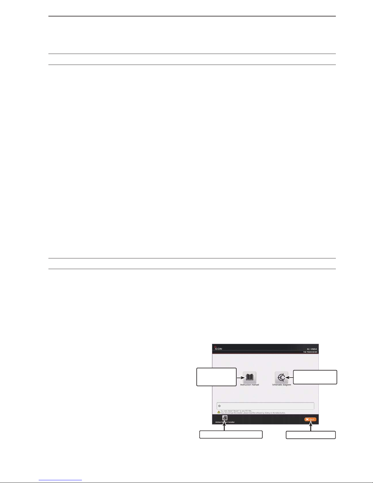
Starting the CD
D
Insert the CD into the CD drive. q
• Double click “Menu.exe” on the CD.
• Depending on the PC setting, the Menu screen shown
below is automatically displayed.
Click the desired button to open the file. w
• To close the Menu screen, click [Quit].
To read the Instruction manual or Schematic diagram,
Adobe® Reader® is required. If you have not installed it,
please install the Adobe® Reader® on the CD or downloaded it from Adobe Systems Incorporated’s web
site.
Quits the Menu screen
Installs the Adobe® Reader
®
Opens the
Instruction manual
(this manual)
Opens the
Schematic diagram
v
FUNCTIONS AND FEATURES of Adobe® Reader
®
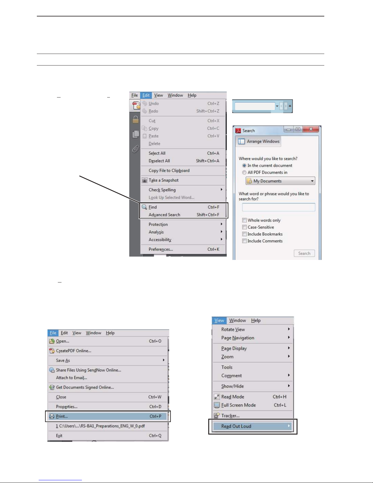
The following functions and features can be used with Adobe® Reader®.
• Keyword search
Click “Find (Ctrl+F)” or “Advanced
Search (Shift+Ctrl+F)” in the Edit
menu to open the search screen.
This is convenient when search-
ing for a particular word or phrase
in this manual.
* The Menu screen may differ, de-
pending on the Adobe® Reader®
version.
• Find screen
• Advanced search screen
Click to open the Find or Search
screen or Advanced search screen.
• Printing out the desired pages.
Click “Print...(Ctrl+P)” in File menu, and then select
the paper size and page numbers you want to print.
* The printing setup may differ, depending on the
printer. Refer to your printer’s instruction manual
for details.
* Select “A4” size to print out the page in the equal-
ized size.
• Read Out Loud feature.
The Read Out Loud feature reads aloud the text in
this Instruction Manual.
Refer to the Adobe® Reader® Help for the details.
( This feature may not be usable, depending on your
PC environment including the operating system.)
* The screen may differ, depending on the Adobe® Reader®
version.

vi
DESCRIPTION INFORMATION
This instruction manual is described based on the following manner.
“ ” (Quotation marks): Used to indicate icons, setting items, and screen titles displayed on the screen.
[ ] (brackets): Used to indicate keys, dials, and knobs.
Routes to the Set mode and setting screen descriptions
Routes to the Set mode, setting screen and the setting items are described in the following manner.
About the transceiver’s illustrations
To indicate the keys and knobs in the operating steps, the transceiver is illustrated as illustrated below.
Band edge warning beep
This function allows you to hear a beep tone when
you tune in or out of an amateur band’s frequency
range. A regular beep sounds when you tune into a
range, and a lower tone error beep will sound when
you tune out of a range.
The Multi-function screens are OFF:
Select the “Beep (Band Edge)” item in the Others q
set screen.
SET [F-7] OTHERS [F-5] Beep (Band Edge)
Rotate [MAIN DIAL] to select the option. w
• Band Edge Beep options:
OFF: Band edge beep is OFF.
ON (Default): When you tune into or out of the de-
fault amateur band’s frequency range,
a beep sounds. (default)
SET [F-7] OTHERS [F-5] Beep (Band Edge)
The Set mode menu screen.
The Multi-function screens are OFF.
The Others set screen.
() Multi-function keys Band key
(F) Function keys Mode keys
Also, the keys and knobs are described in the following
manner.
() Multi-function keys
Example:
Push the Multi-function [METER]() key.
(F) Function key
Example: Push [SCOPE](F).
Mode key
Example: P
ush the Mode key [SSB].
vii
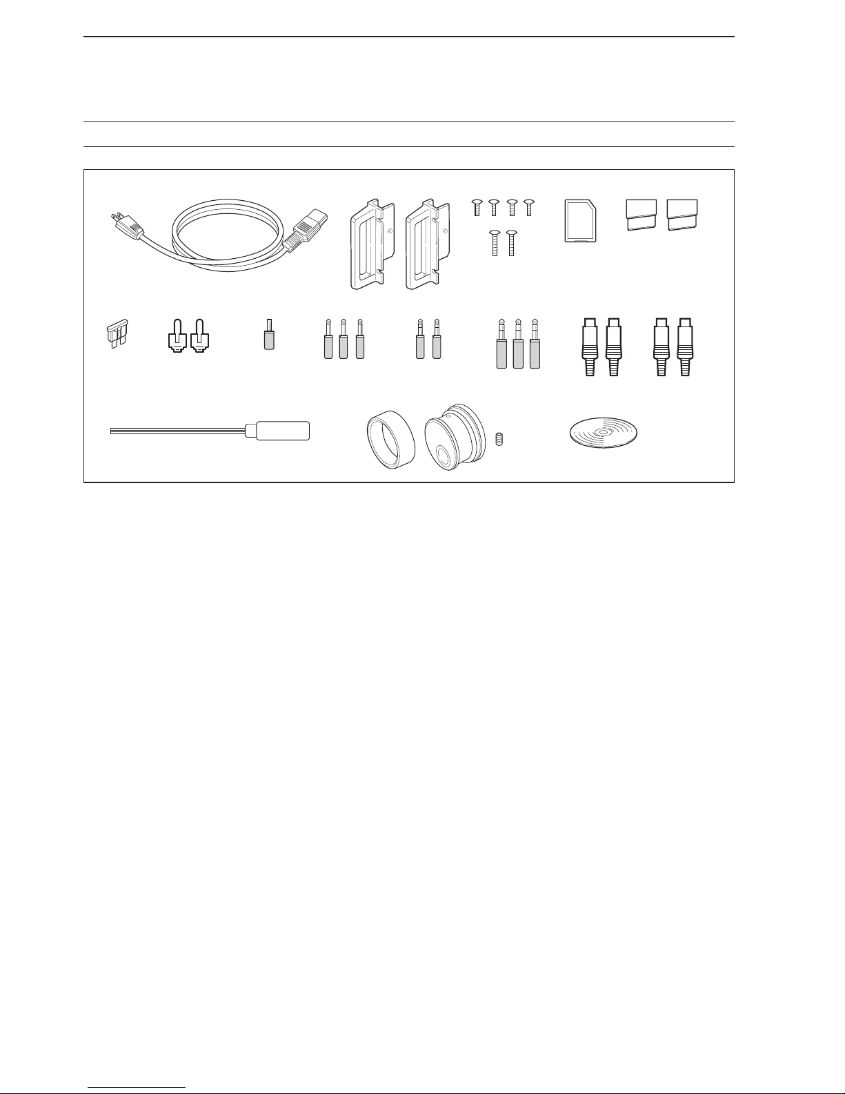
AC power cable q
†
.................................................. 1
Rack mounting handles w ................................ 1 pair
Screws for rack mounting handles e ................... 1 set
SD card r .................................................................1
Feet t .............................................................. 1 pair
Spare fuse (2 A) y .................................................. 1
RCA plugs u ........................................................... 2
DC plug i ............................................................... 1
2-conductor o
1
⁄8″ plugs .......................................... 3
!0 3-conductor 1⁄8″ plugs .......................................... 2
!1 3-conductor 1⁄4″ plugs .......................................... 3
!2 ACC plugs (7-pin) ................................................ 2
!3 ACC plugs (8-pin) ................................................ 2
!4 Hexagonal wrench‡ .............................................. 1
!5 Main dial‡ ............................................................. 1
!6 CD ....................................................................... 1
†
May differ from that shown depending on the version.
‡
See page 3-3 for the Main dial attachment details.
SUPPLIED ACCESSORIES
q
!0 !1 !2 !3
!4 !6!5
yu io
w
er t

viii
TABLE OF CONTENTS
PANEL DESCRIPTION Section 1
F ront panel ……………………………………………………………… 1-2
R ear panel ………………………………………………………………1-12
D isplay ……………………………………………………………………1-14
S creen menu arrangement …………………………………………… 1-16
SET MODE ITEMS Section 2
A bout the Setting screen configuration ……………………………… 2-2
S COPE SET …………………………………………………………… 2-3
V OICE SET ……………………………………………………………… 2-4
K EYER 001 ……………………………………………………………… 2-4
K EYER CW-KEY ……………………………………………………… 2-5
R TTY LOG SET ………………………………………………………… 2-5
R TTY DECODE SET …………………………………………………… 2-5
P SK LOG SET ………………………………………………………… 2-6
P SK DECODE SET …………………………………………………… 2-6
S CAN SET ……………………………………………………………… 2-6
A UDIO SCOPE SET …………………………………………………… 2-6
L EVEL SET ……………………………………………………………… 2-7
A CC SET ………………………………………………………………… 2-8
D ISPLAY SET …………………………………………………………… 2-10
T IME SET ………………………………………………………………2-11
O THERS SET ……………………………………………………………2-11
L OAD SET ………………………………………………………………2-16
S AVE SET ……………………………………………………………… 2-16
A NT TYPE ……………………………………………………………… 2-16
V OX ……………………………………………………………………… 2-17
N B …………………………………………………………………………2-17
F ILTER SHAPE SET ……………………………………………………2-17
INSTALLATION AND CONNECTIONS Section 3
U npacking ……………………………………………………………… 3-2
S electing a location …………………………………………………… 3-2
G rounding ……………………………………………………………… 3-2
A ttaching the rack mounting handle ………………………………… 3-2
C onnecting antenna …………………………………………………… 3-3
R equired connections ………………………………………………… 3-4
D Front panel (Electronic keyer and microphone) ………………… 3-4
D Rear panel (Basic connection) …………………………………… 3-4
A dvanced connections ………………………………………………… 3-5
D Front panel (Microphone, headphones and SD card) …………… 3-5
D Rear panel (Optional products and external equipment) ……… 3-5
D Rear panel (Optional products and external equipment) ……… 3-6
D Rear panel (External keypad and meter) ………………………… 3-6
L inear amplifier connections ………………………………………… 3-7
D Connecting the IC-PW1/EURO …………………………………… 3-7
D Connecting a non-Icom linear amplifier …………………………… 3-7
T ransverter jack information …………………………………………… 3-8
F SK and AFSK (SSTV) connections ………………………………… 3-8

ix
TABLE OF CONTENTS
M icrophones (optional products) ……………………………………… 3-9
D SM-50 ………………………………………………………………… 3-9
D SM-30 ………………………………………………………………… 3-9
D HM-36 ………………………………………………………………… 3-10
BASIC OPERATION Section 4
W hen first applying power …………………………………………… 4-2
P ower ON ……………………………………………………………… 4-3
R D esetting the CPU (initial setup) …………………………………… 4-3
A djusting the Volume level …………………………………………… 4-4
A djusting the Squelch level …………………………………………… 4-4
A djusting the RF gain ………………………………………………… 4-4
S electing Main and Sub bands ……………………………………… 4-5
S electing the VFO or memory mode ………………………………… 4-5
S electing an operating band…………………………………………… 4-6
U D sing the band stacking registers ………………………………… 4-6
S etting the frequency ………………………………………………… 4-7
T D uning with [DIAL] …………………………………………………… 4-7
A D bout the Quick tuning step ………………………………………… 4-7
S D electing the Fine tuning function ………………………………… 4-8
A D bout the Auto tuning step function ……………………………… 4-8
A D bout the 1⁄4 tuning step function ………………………………… 4-9
E D ntering the frequency with the keypad …………………………… 4-9
O perating mode selection ……………………………………………… 4-10
S electing the Meter readout ……………………………………………4-11
D D igital multi-function meter …………………………………………4-11
S D electing the meter type …………………………………………… 4-12
D ial lock function ………………………………………………………4-12
B asic transmit operation ………………………………………………4-13
T D ransmitting ………………………………………………………… 4-13
A D djusting the microphone gain …………………………………… 4-13
D D rive gain adjustment ………………………………………………4-14
T D ransmit power limit …………………………………………………4-14
B and edge warning beep ………………………………………………4-15
E D ntering the user band edge ……………………………………… 4-16
A bout the 5 MHz frequency band operation (USA version only) …4-18
RECEIVE AND TRANSMIT Section 5
C onvenient functions for Receive …………………………………… 5-2
C onvenient functions for Transmit …………………………………… 5-3
O perating SSB ………………………………………………………… 5-4
O perating CW …………………………………………………………… 5-5
A D bout the CW pitch control ………………………………………… 5-6
A D PF (Audio Peak Filter) operation ………………………………… 5-6
A D djusting the Key speed …………………………………………… 5-7
A D bout the CW reverse mode ……………………………………… 5-7
C D W side tone function ……………………………………………… 5-7
A D bout 137 kHz band operation (Europe version only) ………… 5-8

x
TABLE OF CONTENTS
E lectronic keyer functions ……………………………………………… 5-9
M D emory keyer screen ……………………………………………… 5-10
E D diting a Keyer memory ……………………………………………5-11
C D ontest number set mode ………………………………………… 5-12
K D eyer set mode ……………………………………………………… 5-13
O perating RTTY (FSK) …………………………………………………5-14
A D bout the RTTY reverse mode ……………………………………5-15
T D win peak filter ………………………………………………………5-15
F D unctions for the RTTY decoder display …………………………5-16
S D etting the decoder threshold level …………………………………5-17
R D TTY memory transmission ……………………………………… 5-17
A D utomatic transmission/reception setting ………………………… 5-18
E D diting the RTTY memory …………………………………………5-19
T D urning ON the RTTY log ……………………………………………5-20
C D onfirm the RTTY log contents ……………………………………5-21
R D TTY decode set mode ……………………………………………5-22
O perating PSK ………………………………………………………… 5-24
V D ector indicator and Waterfall display ………………………………5-25
F D unctions for the PSK decoder display …………………………… 5-26
A D bout the BPSK and QPSK modes ……………………………… 5-27
A D bout the BPSK31 and BPSK63 modes …………………………5-27
S D etting the decoder threshold level …………………………………5-28
A D bout the PSK reverse mode ……………………………………… 5-28
A D FC/NET function ……………………………………………………5-28
P D SK memory transmission ………………………………………… 5-29
A D utomatic transmission/reception setting ………………………… 5-30
E D diting the PSK memory ……………………………………………5-31
T D urning ON the PSK log ……………………………………………5-32
C D onfirm the PSK log contents ………………………………………5-33
P D SK decode set mode ……………………………………………… 5-34
O perating AM or FM ……………………………………………………5-36
R epeater operation ……………………………………………………5-37
C D hecking the repeater input signal …………………………………5-37
R D epeater tone frequency setting ……………………………………5-38
T one squelch operation …………………………………………………5-39
D ata mode (AFSK) operation …………………………………………5-40
SCOPE OPERATION Section 6
S pectrum scope screen ……………………………………………… 6-2
O D perating the Spectrum scope …………………………………… 6-3
C D enter mode ………………………………………………………… 6-4
F D ixed mode …………………………………………………………… 6-5
D D ual scope screen …………………………………………………… 6-6
M D ini scope screen …………………………………………………… 6-6
S D cope attenuator …………………………………………………… 6-7
A D djusting the Reference level ……………………………………… 6-8
S D weep speed ………………………………………………………… 6-9
S D cope set screen ……………………………………………………6-10
U D SB mouse operation ……………………………………………… 6-14
A udio scope screen ……………………………………………………6-15
A D udio scope set mode ………………………………………………6-16

xi
TABLE OF CONTENTS
Functions for Receive Section 7
P reamplifier ……………………………………………………………… 7-2
A ttenuator ……………………………………………………………… 7-2
R IT function ……………………………………………………………… 7-3
ï RIT monitor function ………………………………………………… 7-3
A GC function control …………………………………………………… 7-4
ï Selecting the preset value ………………………………………… 7-4
ï Adjusting the AGC time constant ………………………………… 7-4
ï Setting the AGC time constant preset value ……………………… 7-4
T win PBT operation …………………………………………………… 7-5
I F filter selection ………………………………………………………… 7-6
ï IF filter selection ……………………………………………………… 7-6
ï DSP filter shape ……………………………………………………… 7-7
ï Roofing filter selection ……………………………………………… 7-7
ï 1.2 kHz Filter calibration …………………………………………… 7-8
ï Filter shape set mode ……………………………………………… 7-9
D ualwatch operation ……………………………………………………7-10
N oise blanker ……………………………………………………………7-11
ï NB Set mode …………………………………………………………7-11
N oise reduction ………………………………………………………… 7-12
D igital selector …………………………………………………………7-12
N otch function …………………………………………………………… 7-13
ï Auto notch function …………………………………………………7-13
ï Manual notch function ………………………………………………7-13
A uto tuning function ……………………………………………………7-14
FUNCTIONS FOR TRANSMIT Section 8
About the VOX function ………………………………………………… 8-2
Turning ON D the VOX function ……………………………………… 8-2
A D djusting the VOX function ………………………………………… 8-2
V D OX set mode ……………………………………………………… 8-3
About the Break-in function …………………………………………… 8-4
S D emi break-in operation …………………………………………… 8-4
F D ull break-in operation ……………………………………………… 8-4
About the ∂TX function ………………………………………………… 8-5
∂ D TX monitor function ……………………………………………… 8-5
About the Monitor function …………………………………………… 8-5
Setting the Speech compressor (SSB only) ………………………… 8-6
Setting the Transmit filter width (SSB only) ………………………… 8-6
Operating the Split frequency ………………………………………… 8-7
About the Quick split function ………………………………………… 8-8
S D plit lock function …………………………………………………… 8-8
VOICE RECORDER FUNCTIONS Section 9
R ecording function ……………………………………………………… 9-2
R ecording a QSO ……………………………………………………… 9-3
Q D uick recording ……………………………………………………… 9-3
B D asic recording ……………………………………………………… 9-3
P laying back the recorded audio (QSO) ……………………………… 9-4
O perating while playing back ………………………………………… 9-5

xii
TABLE OF CONTENTS
D eleting a recorded audio file ………………………………………… 9-6
D eleting a recorded audio folder ……………………………………… 9-6
I nstant replay function ………………………………………………… 9-7
R ecording the communication audio ………………………………… 9-8
P laying back the recorded audio ……………………………………… 9-8
R ecording or playing back a TX message …………………………… 9-9
R D ecording …………………………………………………………… 9-9
P D laying back ………………………………………………………… 9-9
P D rogramming a TX message name ………………………………9-10
T ransmitting a recorded message ……………………………………9-11
S D ingle TX ………………………………………………………………9-11
R D epeat TX …………………………………………………………… 9-11
S D etting the transmit level …………………………………………… 9-12
V oice Set mode ………………………………………………………… 9-13
S aving a voice memory onto an SD card or USB flash drive ………9-14
USING AN SD CARD OR USB MEMORY Section 10
A bout the SD card ………………………………………………………10-2
I D nserting the SD card ………………………………………………10-2
R D emoving the SD card ………………………………………………10-2
S D/USB-Memory menu screen ………………………………………10-3
S D ave set screen ………………………………………………………10-4
L D oad set screen ………………………………………………………10-4
S aving the setting data onto an SD card or USB flash drive ………10-5
L oading the saved data files onto an SD card or USB flash drive … 10-6
S aving with a different file name ………………………………………10-7
D eleting a data file ………………………………………………………10-8
F ormatting an SD card or USB flash drive …………………………… 10-8
U nmounting an SD card or USB flash drive ………………………… 10-9
S creen Capture function …………………………………………… 10-10
C D apturing the screen ……………………………………………… 10-10
V D iewing the captured screen …………………………………… 10-10
MEMORY OPERATION Section 11
M emory channels ………………………………………………………11-2
M emory channel selection …………………………………………… 11-2
U D sing the M-CH [p] or [q] keys ……………………………………11-2
U D sing the keypad ……………………………………………………11-2
M emory list screen ………………………………………………………11-3
S D electing a memory channel using the Memory list screen …… 11-3
C D onfirming programmed memory channels ……………………… 11-3
Entering Memory channel contents …………………………………11-4
Entering D in the VFO mode …………………………………………11-4
Entering D in the Memory mode ………………………………………11-4
C opying Memory contents ……………………………………………11-5
C D opying in the VFO mode ………………………………………… 11-5
C D opying in the Memory mode ………………………………………11-5
M emory names …………………………………………………………11-6
E D diting (programming) memory names ……………………………11-6
M emory clearing………………………………………………………… 11-6

xiii
TABLE OF CONTENTS
M emo pads ………………………………………………………………11-7
E D ntering frequencies and operating modes into Memo pads ……11-7
C D alling up a frequency and operating mode from Memo pads …11-8
U D sing the Memo pad list screen ……………………………………11-8
SCANS Section 12
S can types ………………………………………………………………12-2
P reparation ………………………………………………………………12-3
S can set mode …………………………………………………………12-4
P rogrammed scan ………………………………………………………12-5
F ine programmed scan …………………………………………………12-6
M emory scan operation ………………………………………………12-7
S elect memory scan operation ………………………………………12-7
S etting select memory channels ………………………………………12-8
S D etting in the Scan screen …………………………………………12-8
S D etting in the Memory list screen ………………………………… 12-8
E D rasing the select scan setting ……………………………………12-8
∂ F scan operation ………………………………………………………12-9
F ine ∂F scan ……………………………………………………………12-9
T one scan …………………………………………………………… 12-10
V oice squelch control function ……………………………………… 12-10
ANTENNA TUNER OPERATION Section 13
A ntenna connection and selection ……………………………………13-2
R eceive Antenna-I/O selection ……………………………………… 13-2
A ntenna memory settings ………………………………………………13-3
A D ntenna type selection ………………………………………………13-4
A D ntenna selection mode ……………………………………………13-5
T D emporary memory ………………………………………………… 13-5
R D eceive antenna I/O setting ………………………………………… 13-6
A bout the Antenna tuner ………………………………………………13-7
U sing the Antenna tuner operation ……………………………………13-7
I D f the tuner cannot tune the antenna ……………………………… 13-8
CLOCK AND TIMERS Section 14
T ime set mode …………………………………………………………14-2
S D etting the Date ………………………………………………………14-2
S D etting the Current time ……………………………………………14-2
S D etting the UTC Offset ………………………………………………14-2
S D electing the CLOCK2 Function ……………………………………14-3
S D etting the CLOCK2 UTC Offset …………………………………… 14-3
E D ntering the CLOCK2 Name ……………………………………… 14-3
S D etting the NTP Function ……………………………………………14-4
S D etting the NTP Server address ……………………………………14-4
S etting the Daily timer …………………………………………………14-5
S etting the Sleep timer …………………………………………………14-6
T imer operation ………………………………………………………… 14-6

xiv
SET MODE Section 15
S et mode description …………………………………………………… 15-2
S D et mode operation …………………………………………………15-2
S D creen arrangement …………………………………………………15-3
L evel set screen …………………………………………………………15-4
A CC set screen ………………………………………………………… 15-6
D isplay set screen …………………………………………………… 15-10
T ime set screen ……………………………………………………… 15-12
O thers set screen …………………………………………………… 15-13
MAINTENANCE Section 16
A djusting the Main dial brake …………………………………………16-2
U sing the Voice synthesizer operation ………………………………16-2
S WR reading ……………………………………………………………16-3
C alibration the Frequency (approximate) …………………………… 16-4
S etting My call sign ……………………………………………………16-5
C leaning ………………………………………………………………… 16-7
R esetting the CPU ………………………………………………………16-7
A bout protection indications ……………………………………………16-8
O pening the transceiver’s case ………………………………………16-8
F use replacement ……………………………………………………… 16-9
C lock backup battery replacement ……………………………………16-9
T roubleshooting ……………………………………………………… 16-10
D Transceiver power ………………………………………………… 16-10
D Transmit and receive ……………………………………………… 16-10
D Scanning …………………………………………………………… 16-11
D Display ……………………………………………………………… 16-11
UPDATING THE FIRMWARE Section 17
G eneral …………………………………………………………………17-2
D Checking the firmware version …………………………………… 17-2
P reparation ………………………………………………………………17-3
D File downloading …………………………………………………… 17-3
F irmware update— using an SD card/USB flash drive ……………17-4
CONTROL COMMAND Section 18
Remote control (CI-V) information …………………………………… 18-2
CI-V connection D …………………………………………………… 18-2
Preparing D ……………………………………………………………18-2
Data format D ……………………………………………………………18-2
Data content description D ………………………………………… 18-10
TABLE OF CONTENTS

xv
TABLE OF CONTENTS
SPECIFICATIONS AND OPTIONS Section 19
S pecifications ……………………………………………………………19-2
D General ………………………………………………………………19-2
D Transmitter ……………………………………………………………19-2
D Receiver ……………………………………………………………… 19-3
D Antenna tuner ………………………………………………………… 19-3
O ptions …………………………………………………………………19-4
CONNECTOR INFORMATION Section 20
A CC socket ………………………………………………………………20-2
M icrophone connector …………………………………………………20-3
[ ELEC-KEY] jack ………………………………………………………20-3
[ KEY] jack ……………………………………………………………… 20-3
[ EXT KEYPAD] jack …………………………………………………… 20-4
[ REF I/O] connector ……………………………………………………20-4
[ X-VERTER] connector …………………………………………………20-4
[ RELAY] jack …………………………………………………………… 20-4
[ METER] jack …………………………………………………………… 20-5
[ REMOTE] jack …………………………………………………………20-5
[ DC OUT] jack …………………………………………………………… 20-5
[ EXT-SP] jack …………………………………………………………… 20-5
[ S/P DIF] jack …………………………………………………………… 20-5
[ RX-I/O] connector ………………………………………………………20-5
INDEX

1-1
PANEL DESCRIPTION Section 1
F ront panel ……………………………………………………………… 1-2
R ear panel ………………………………………………………………1-12
D isplay ……………………………………………………………………1-14
S creen menu arrangement …………………………………………… 1-16
1-2
1
PANEL DESCRIPTION
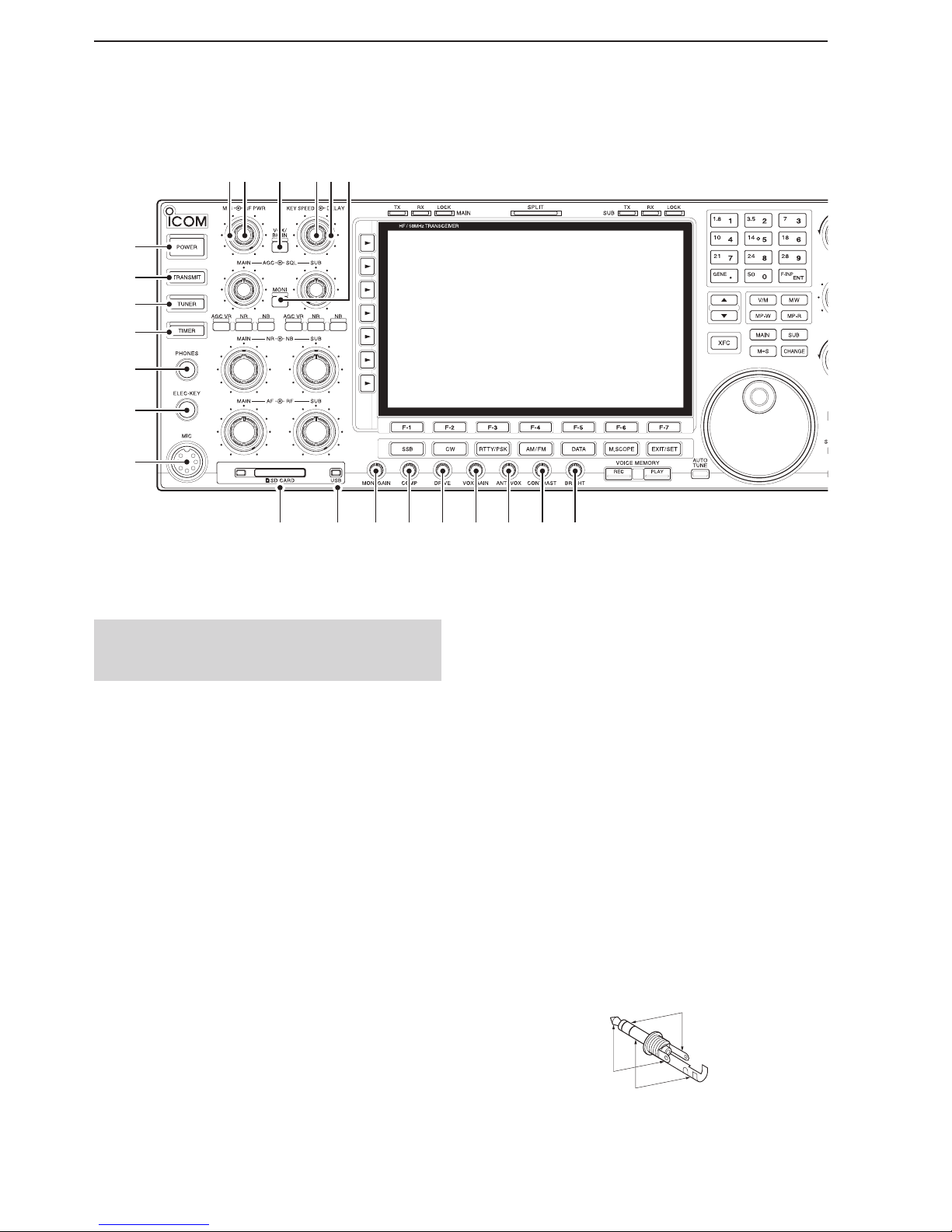
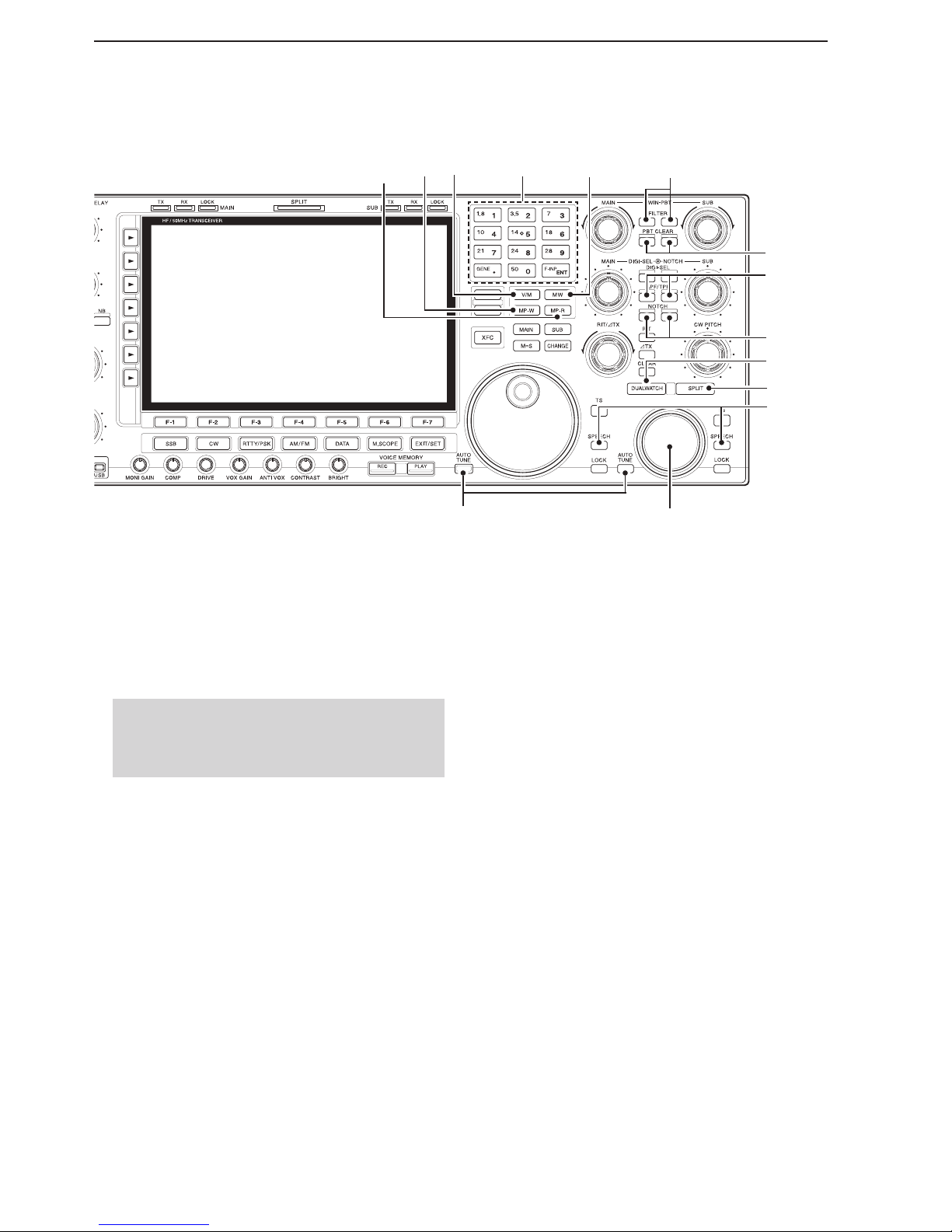
q POWER KEY [POWER] (pp. 4-3, 14-6)
First, turn ON the internal power supply. The internal
power supply switch is located on the rear panel.
(p. 1-12)
Push to turn ON the transceiver power.
• The [POWER] indicator above this key lights blue.
Hold down for 1 second to turn OFF the power.
• The [POWER] indicator lights orange when the transceiver is OFF, but the internal power supply is turned
ON.
w TRANSMIT KEY [TRANSMIT] (p. 4-13)
Push to transmit, release to receive.
• The [TX] indicator lights red while transmitting and the
[RX] indicator lights green when the squelch is open.
e ANTENNA TUNER KEY [TUNER] (p.13-7)
Momentarily push to turn the tuner ON or OFF
(bypass.)
• The [TUNER] indicator above this key lights white
when the tuner is turned ON, and goes off when the
tuner is turned OFF (bypassed).
Hold down for 1 second to manually start the
tuner.
•
The [TUNER] indicator blinks red during manual tuning.
• When the tuner cannot tune the antenna, the tuning
circuit is automatically bypassed after 20 seconds.
r TIMER KEY [TIMER] (p. 14-5)
Push to turn ON or OFF the sleep or daily timer
function.
• The [TIMER] indicator above this key lights white
when the timer is in use.
Hold down for 1 second to enter the Timer set
screen.
t HEADPHONE JACK [PHONES]
(p. 3-5)
Connect standard stereo headphones.
• Output power: 50 mW with an 8 Ω load.
• When headphones are connected, the internal speaker
and any connected external speaker do not function.
y
ELECTRONIC KEYER JACK [ELEC-KEY] (p. 20-3)
Connect a paddle to activate the internal electronic
keyer for CW operation.
• Select the internal electronic keyer, bug-key or straight
key operation in the Keyer set screen. (p. 5-13)
• A straight key jack is located on the rear panel. See
[KEY] on page 1-13.
• Set the keyer polarity (dot and dash) in the Keyer set
screen. (p. 5-13)
• Eight keyer memory channels can be used. (p. 5-11)
dash
dot
com
Front panel
q
w
e
r
t
y
u
i o !0 !1 !2 !3 !4 !5 !6
!8
!9
@1
@2
@0
!7

1-3
1
PANEL DESCRIPTION
u MICROPHONE CONNECTOR [MIC]
Connect an optional microphone.
• See page 3-4 for appropriate microphones.
• See page 20-3 for microphone connector information.
i SD CARD SLOT [SD CARD] (pp. 3-5, 10-2)
Insert the supplied SD card for both reading and storing a wide variety of the transceiver’s information and
data.
• The indicator beside the slot lights, or blinks when reading from or writing to the card.
• Push the card once to remove it.
o USB INDICATOR [USB]
(p. 10-4)
Lights while accessing a USB flash drive inserted to
the [USB A] port.
!0
MONITOR GAIN CONTROL [MONI GAIN] (p. 8-5)
Rotate to adjust the transmit IF signal monitor level.
!1 COMPRESSION LEVEL CONTROL [COMP]
(p. 8-6)
Rotate to adjust the speech compression level in
SSB.
!2 DRIVE GAIN CONTROL [DRIVE] (p. 4-14)
Rotate to adjust the transmitter level at the driver
stage. Activates in all modes
(except SSB with [COMP]
OFF)
.
!3 VOX GAIN CONTROL [VOX GAIN] (p. 8-2)
Rotate to adjust the transmit/receive switching
threshold level for VOX operation.
!4 ANTI VOX CONTROL [ANTI VOX] (p. 8-2)
Adjusts the VOX deactivate level to prevent un-
wanted VOX activation from the speaker or other
sounds.
!5 DISPLAY CONTRAST CONTROL [CONTRAST]
Adjusts the display contrast.
!6 DISPLAY BRIGHTNESS CONTROL [BRIGHT]
Adjusts the display brightness.
!7 MONITOR KEY [MONI] (p. 8-5)
Push to monitor your transmitted signal.
• The CW sidetone functions regardless of the [MONI] key
setting in the CW mode.
• The [MONI] indicator above this key lights white while
the function is activated.
!8 BREAK-IN DELAY CONTROL [DELAY] (p. 8-4)
Rotate to adjust the transmit-to-receive switching
delay time in the CW semi-break-in mode.
!9 ELECTRONIC CW KEYER SPEED CONTROL
[KEY SPEED] (p. 5-7)
Rotate to adjust the internal electronic CW keyer’s
speed to between 6 wpm (minimum) and 48 wpm
(maximum).
• The keyer’s speed is displayed.
@0 VOX/BREAK-IN KEY [VOX/BK-IN]
Push to turn the VOX function ON or OFF in the
SSB, AM, or FM mode. (p. 8-2)
Push to turn the break-in function ON (Semi break-
in, Full break-in)
or OFF in the CW mode. (p. 8-4)
Hold down for 1 second to enter the VOX set
screen. (p. 8-3)
What is the VOX function?
The VOX function (voice operated transmission) starts
transmission without pushing the transmit key or PTT
switch when you speak into the microphone, then automatically returns to receive when you stop speaking.
What is the break-in function?
The break-in function toggles between transmit and
receive with CW keying. Full break-in (QSK) can monitor the receive signal during keying.
@1 RF POWER CONTROL [RF PWR] (p. 4-13)
Rotate to continuously vary the RF output power
from less than 5 watts (minimum) to 200* watts
(maximum).
*AM mode: less than 5 W to 50 W
• The output power setting is displayed.
@2 MIC GAIN CONTROL [MIC]
Rotate to adjust microphone gain.
• The transmit audio tone in the SSB, AM, or FM mode
can be independently adjusted in the Level set screen.
(p. 4-13)
How to set the microphone gain.
Adjust the [MIC] control so that the ALC meter swings
within the ALC range during normal voice level transmission in the SSB or AM mode. (The ALC meter must
be selected.)
1-4
1
PANEL DESCRIPTION
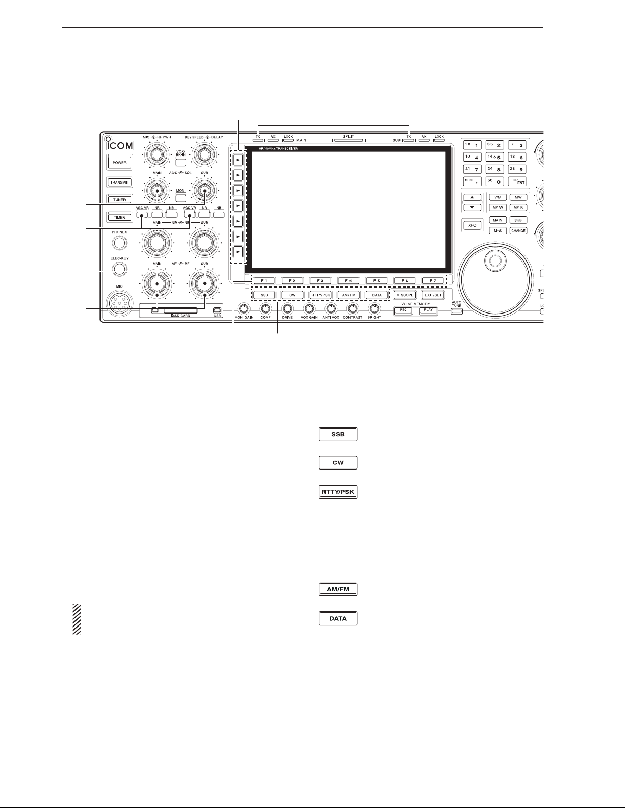
@3 AGC CONTROL [AGC] (p. 7-4)
Rotate to adjust the continuously-variable AGC cir-
cuit time constant.
• To use the [AGC] control, push the appropriate band’s
[AGC VR] (The [AGC VR] indicator lights white).
@4 AGC VOLUME KEY [AGC VR] (p. 7-4)
Push to toggle the [AGC] control ON or OFF.
• Use the [AGC] control to set the AGC time constant
when switched ON.
• The [AGC VR] indicator above this key lights white
when the control is ON.
Hold down for 1 second to turn OFF the AGC
function.
@5 AF CONTROL [AF] (p. 4-4)
Rotate to adjust the audio output level of the speak-
er or headphones.
@6 RF GAIN CONTROL [RF] (p. 4-4)
Rotate to adjust the RF gain level.
While rotating the RF gain control, you may hear
noise. This comes from the DSP unit and does
not indicate a malfunction.
@7 FUNCTION KEYS [F-1]–[F-7]
Push to select the function indicated in the display
above these keys.
• Functions vary, depending on the operating mode.
@8 MODE KEYS
Selects the desired mode. (p. 4-10)
•
The Voice synthesizer announces the selected mode.
(p. 16-2)
Push to alternately
select the USB or
LSB mode.
Push to alternately select the CW or
CW-R (CW reverse) mode.
Push to toggle between the RTTY and
PSK modes.
Hold down for 1 second to toggle be-
tween the RTTY and RTTY-R (RTTY re-
verse)
modes.
Hold down for 1 second to toggle be-
tween the PSK and PSK-R (PSK reverse)
modes.
Push to alternately
select the
AM or FM
mode.
Push to toggle between
the
SSB, AM, or
FM data (USB-D, LSB-D, AM-D, FM-D) and
voice modes.
Hold down for 1 second to toggle be-
tween D1, D2, and D3.
@9 TRANSMIT INDICATOR [TX]
Lights red while transmitting.
• The SUB band’s [TX] indicator lights only when in split
operation.
Front panel (Continued)
@8
@7
@4
@6
@3
@5
@9#0
1-5
1
PANEL DESCRIPTION
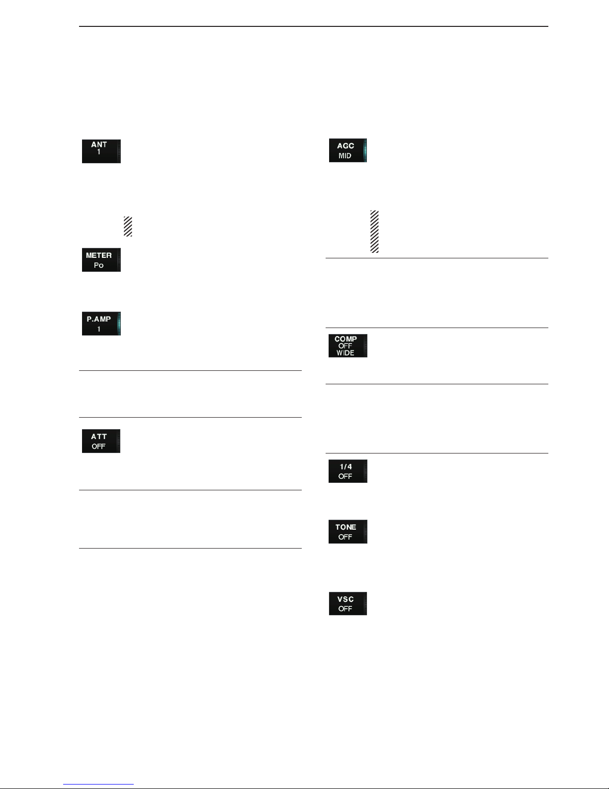
#0 MULTI-FUNCTION KEYS
Push to select the functions indicated in the display
to the right of these keys.
• Functions vary, depending on the operating mode.
Push to select the ANT1, ANT2, ANT3 or
ANT4 antenna connector. (p. 13-2)
Hold down for 1 second to display the
antenna selection memory. (p.13-5)
• When the receive antenna is activated, the
antenna that is connected to [ANT4] is used
only for receive.
When a transverter is used, this [ANT]
does not function and “TRV” appears.
Push to select the RF power (Po), SWR,
ALC, COMP, Vd or Id metering while
transmitting. (p. 4-11)
Hold down for 1 second to turn the Digital
multi-function meter ON or OFF. (p. 4-11)
Push to select one of two receive RF
preamps, or bypass them. (p. 7-2)
• “P.AMP1” activates a 10 dB preamp.
• “P.AMP2” activates a 16 dB high-gain pre-
amp.
What is a preamp?
A preamp amplifies received signals in the front end
circuit to improve S/N ratio and sensitivity. Select
“P.AMP1” or “P.AMP2” when receiving weak signals.
Push to select the 6 dB, 12 dB or 18 dB
attenuator. (p. 7-2)
Hold down for 1 second to select the 3
dB, 6 dB, 9 dB, 12 dB, 18 dB, or 21 dB
attenuator. (p. 7-2)
What is an attenuator?
An attenuator prevents a desired signal from distorting
when very strong signals are near the desired frequency, or when very strong electric fields, such as from a
broadcasting station, are near your location.
Push to activate and then select the
“FAST,” “MID,” or “SLOW” AGC time constant. (p. 7-4)
• In the FM mode, only “FAST” is selectable.
Hold down for 1 second to enter the AGC
set mode. (p. 7-4)
The AGC time constant can be set be-
tween 0.1 to 8.0 second (depending on the
mode)
, or turned OFF. When AGC is
“OFF,” the S-meter does not function.
What is AGC?
The AGC controls receiver gain to produce a constant
audio output level, even when the received signal
strength varies dramatically. Select “FAST” for tuning
and then select “MID” or “SLOW” depending on the receiving condition.
Turns the speech compressor ON or
OFF in the SSB mode. (p. 8-6)
Selects the narrow, middle or wide com-
pression when held down for 1 second.
What is a speech compressor?
A speech compressor compresses the transmitter audio input to increase the average audio output level,
and therefore increase the talk power. This function
is effective for long-distance communication, or when
propagation conditions are poor.
Push to turn the 1⁄4-speed tuning func-
tion ON or OFF in the SSB data, CW,
RTTY and PSK modes. (p. 4-9)
•
1
⁄4 function sets the dial rotation to 1⁄4 of the
normal speed for fine tuning.
In the FM mode, push to toggle between
the tone encoder, tone squelch function
and no-tone operation. (p. 5-39)
In the FM mode, hold down for 1 second
to enter the Tone set mode. (pp. 5-38,
5-39)
Push to turn the Voice squelch control
function ON or OFF. This is useful for
scanning. (p. 12-10)
1-6
1
PANEL DESCRIPTION
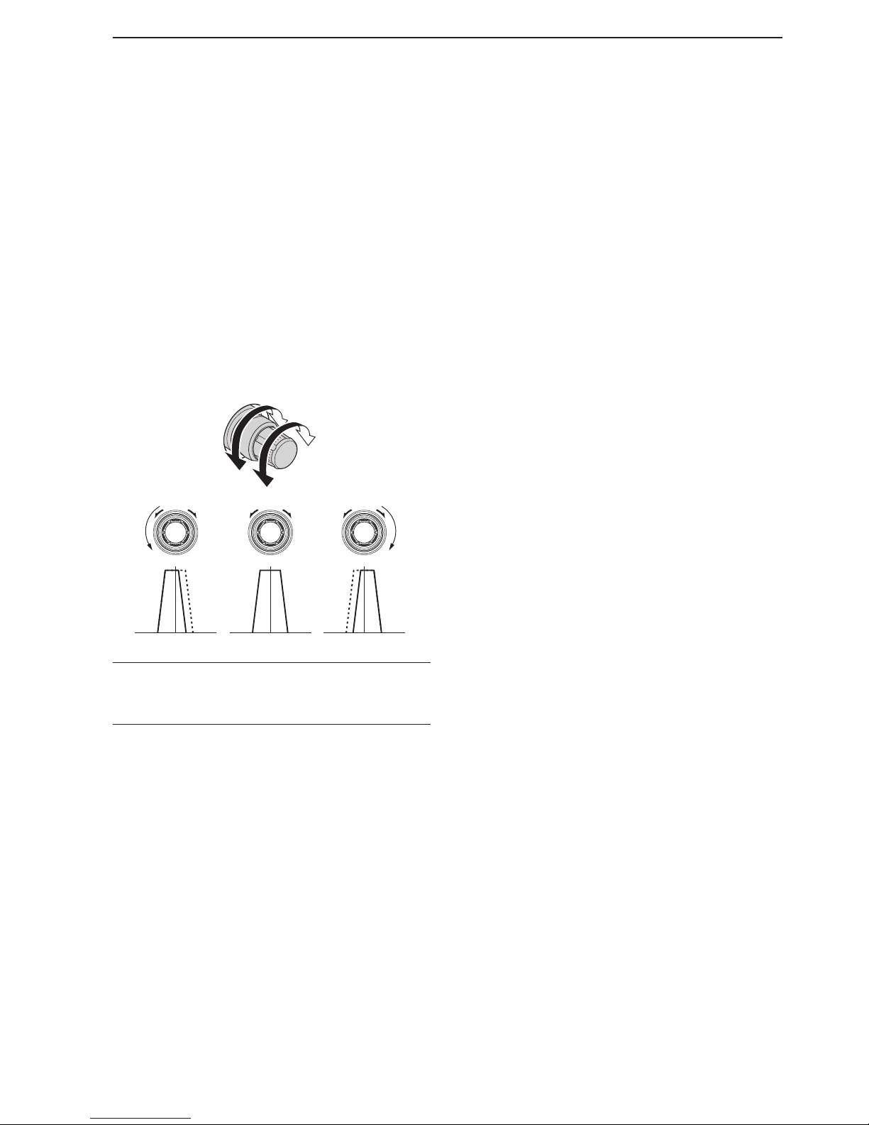
#1 SQUELCH CONTROL [SQL] (p. 4-4)
Rotate to adjust the squelch threshold level. The
squelch removes noise output from the speaker
(closed condition) when no signal is received.
• The squelch is particularly effective for FM. It is also
available for other modes.
• 11 to 12 o’clock position is recommended for any setting
of the [SQL] control.
S-meter
squelch
Noise squelch
Squelch
is open.
Squelch
threshold
#2 NOISE BLANKER KEY [NB] (p. 7-11)
Push to turn the noise blanker ON or OFF.
The noise blanker reduces pulse-type noise such
as that generated by automobile ignition systems.
This function cannot be used in the FM mode, or
for non-pulse-type noise.
• The [NB] indicator above this key lights white while
the function is activated.
Hold down for 1 second to enter the Noise blank-
er set mode.
#3
NOISE REDUCTION KEY [NR]
(p. 7-12)
Push to turn the DSP noise reduction ON or OFF.
• The [NR] indicator above this key lights white when the
function is activated.
#4 NOISE REDUCTION LEVEL CONTROL [NR]
(p. 7-12)
Adjusts the DSP noise reduction level when the noise
reduction is in use. Set for maximum readability.
• To use this control, push the appropriate Main or Sub
band’s [NR].
#5 NOISE BLANKER CONTROL [NB] (p. 7-11)
Adjust the noise blanker threshold level.
• To use this control, push appropriate band’s [NB] key.
#6 LOCK INDICATOR [LOCK] (p. 4-12)
Lights when the dial lock function is activated.
#7 FUNCTION DISPLAY (p. 1-14)
Shows the operating frequency, function key menus,
Spectrum scope screen, Memory channel screen,
Set mode settings, and so on.
Front panel (Continued)
$8 $6 $3$9%0
#6 #7$7#8 $1#9 $0 $2
$5 $4
#5
#3
#4
#2
#1

1-7
1
PANEL DESCRIPTION
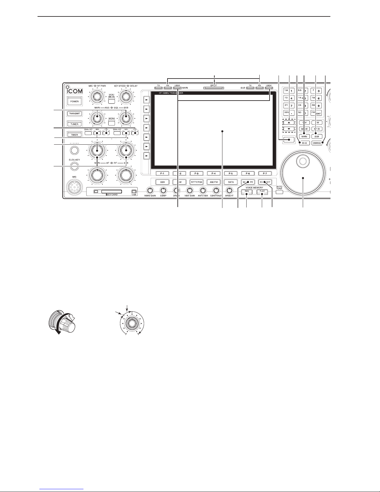
#8
MINI SPECTRUM SCOPE KEY [M.SCOPE] (p. 6-2)
Push to t
urn the Mini spectrum scope screen ON
or OFF.
• You can simultaneously display the Mini spectrum
scope screen with other screens, such as the Memory or Set mode screens.
Hold down for 1 second to t
urn ON the regular
spectrum scope screen.
#9 VOICE MEMORY RECORD KEY [REC]
Push to store the previous received signal for the
preset time period. This function is called Instant
replay. (p. 9-7)
• The preset time period can be set in the Voice set
screen. (p. 9-13)
Hold down for 1 second to record a QSO (Communication) audio onto a memory device. (p. 9-3)
• Hold down again for 1 second to stop recording.
• The recorded memory device can be selected in the
Voice set screen. (p. 9-13)
$0 VOICE MEMORY PLAY BACK KEY [PLAY]
(pp. 9-2, 9-8)
Push to playback the last 5 seconds of the Instant
replay memory.
• The playback time can be changed in the Voice set
screen.
Hold down for 1 second to playback all of the in-
stant replay memory.
• The recording time can be changed in the Voice set
screen.
$1 EXIT/SET KEY [EXIT/SET]
Push to exit, or return to the previous screen in-
dication during Spectrum scope, Memory, Scan
or Set screen display.
Hold down for 1 second to display the Set mode
menu screen. (p. 15-3)
$2 MAIN DIAL
Changes the displayed frequency (Main band), se-
lects set mode option, and so on.
$3
MAIN/SUB CHANGE KEY [CHANGE] (pp. 7-10, 8-7)
Push to toggle the frequency and selected memory
channel between the Main and Sub band readouts.
• When the split frequency function is ON, push to toggle
between the transmit frequency and the receive frequency.
$4 SUB BAND ACCESS KEY [SUB]
Push to select the Sub band readout.
• The Sub band readout frequency is clearly displayed.
$5 MAIN BAND ACCESS KEY [MAIN]
Push to select the Main band readout.
• The Main band readout frequency is clearly displayed.
The Sub band readout functions only during split operation or Dualwatch.
$6 MAIN/SUB EQUALIZING KEY [M=S] (p. 8-7)
Hold down for 1 second to equalize the Sub band
readout frequency to the Main band readout frequency.
$7 MEMORY CHANNEL UP/DOWN KEYS [p]/[q]
(p. 11-2)
Push to select the desired memory channel.
• Memory channels can be selected both in the VFO and
the memory modes.
$8 TRANSMIT FREQUENCY CHECK KEY [XFC]
(p. 6-5)
Hold down to monitor the transmit frequency (includ-
ing ∂TX frequency offset)
during split frequency op-
eration.
• While holding down, the transmit frequency can be
changed with [MAIN DIAL], keypad, memo pad or [Y]/
[Z] keys.
• When the split lock function is turned ON, push [XFC] to
cancel the Dial lock function. (pp. 8-7, 8-8)
$9 RECEIVE INDICATOR [RX]
Lights green while receiving a signal and when the
squelch is open.
%0 SPLIT OPERATION INDICATOR [SPLIT] (p. 8-7)
Lights white during split frequency operation.
1-8
1
PANEL DESCRIPTION
%1 AUTOMATIC TUNING KEY [AUTO TUNE]
Push to turn ON the Automatic tuning function in the
CW or AM mode.
IMPORTANT!
When receiving a weak signal, or receiving a signal
with interference, the automatic tuning function may
tune the receiver to an undesired signal.
%2 SUB DIAL
Changes the displayed frequency in the Sub band.
%3 SPEECH KEY [SPEECH] (p. 16-2)
Push to announce the S-meter level and the se-
lected operating frequency.
• You can change the speech language, speech speed,
and speech contents in the Others set screen.
(p. 15-14)
Hold down for 1 second to announce the select-
ed operating mode.
%4 SPLIT KEY [SPLIT] (pp. 8-7, 8-8)
Push to turn the split function ON or OFF.
Hold down for 1 second to turn the split func-
tion ON and equalize the Sub band frequency to
the Main band in non-FM modes, and then sets
the Sub band readout for frequency input mode.
(Quick split function)
• In the FM mode, the Sub band frequency is shifted
by the preset frequency offset from the Main band
readout frequency. (p. 15-14)
• The quick split function can be turned OFF in the Others set screen. (p. 15-13)
After entering a frequency offset, push to turn
ON the split function. The Sub band frequency
is shifted the offset amount from the Main band
frequency.
%5 DUALWATCH KEY [DUALWATCH] (p. 7-10)
Push to turn the Dualwatch function ON or OFF.
Hold down for 1 second to turn the Dualwatch
function ON, and equalize the Main/Sub band
frequency to the Sub/Main band. (Quick dualwatch function)
• The Quick Dualwatch function can be turned OFF in
the Others set screen. (p. 15-13)
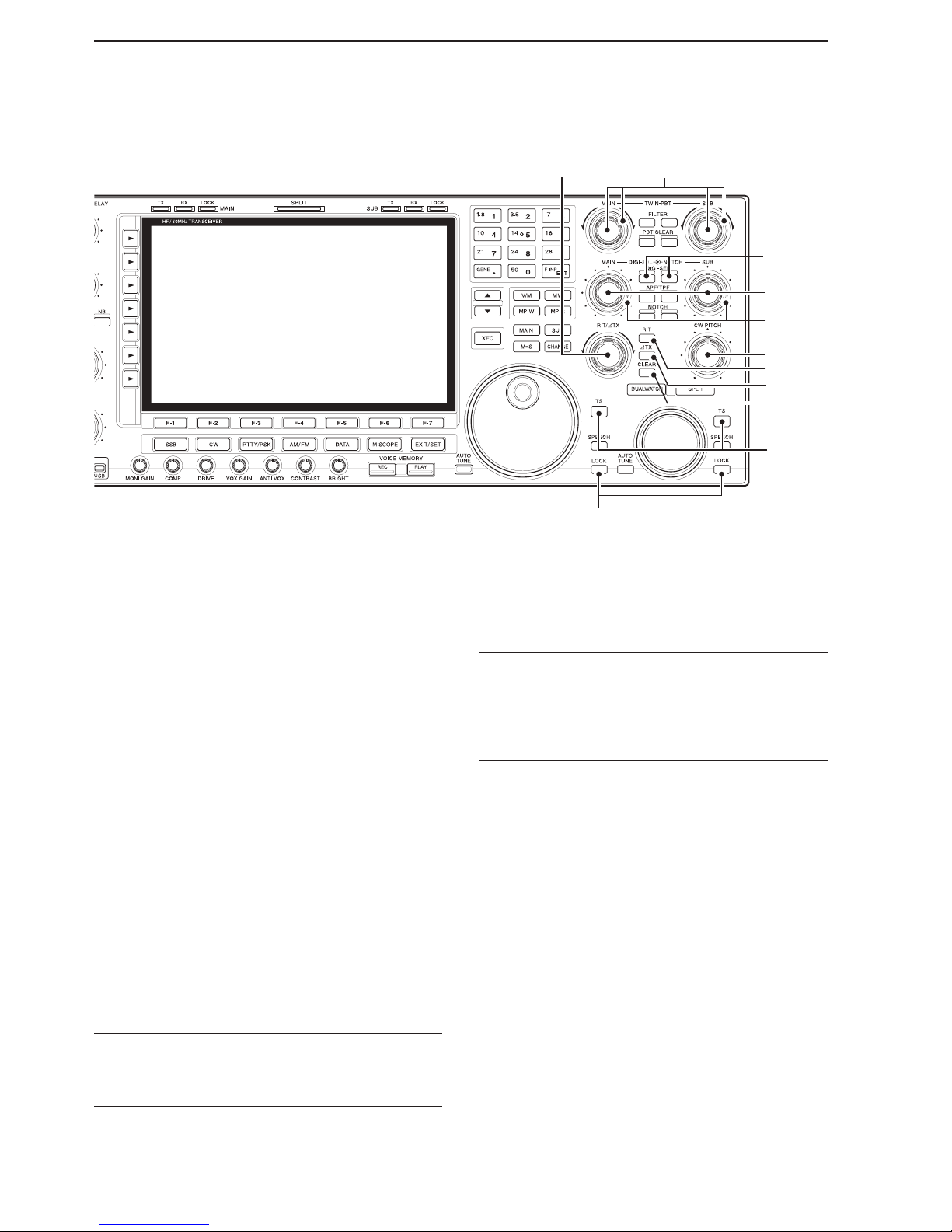
Front panel (Continued)
^4%9^3 ^2
^0
^1
%4
%5
%6
%8
%7
%3
%1 %2

1-9
1
PANEL DESCRIPTION
%6 NOTCH KEY [NOTCH]
(p. 7-13)
Push to select the Notch function between auto,
manual, or OFF in the SSB or AM mode.
Push to turn the Manual notch function ON or
OFF in the CW, RTTY, or PSK mode.
Push to turn the Auto notch function ON or OFF
in the FM mode.
• “
MN
” is displayed when the Manual notch filter is in
use.
• “
AN
” is displayed when the Auto notch filter is in
use.
Hold down for 1 second to select the Manual
notch width from wide, mid, or narrow.
What is the Notch function?
The notch function eliminates unwanted CW or AM
carrier tones while preserving the desired voice signal.
The DSP circuit automatically adjusts the filtering frequency to effectively eliminate unwanted tones.
%7 AUDIO PEAK FILTER/TWIN PEAK FILTER KEY
[APF/TPF]
During CW mode operation (p. 5-6)
Push to turn the Audio peak filter ON or OFF.
• “
APF
” appears when audio peak filter is in use.
Hold down for 1 second to select the APF pass-
band width from WIDE, MID, or NAR or from 320,
160, or 80 Hz, depending on the APF type setting.
During RTTY mode operation (p. 5-15)
Push to turn the Twin peak filter ON or OFF.
• “
TPF
” appears when twin peak filter is in use.
%8 PBT CLEAR KEY [PBT CLEAR] (p. 7-5)
Hold down for 1 second to clear the PBT settings.
• The [PBT CLEAR] indicator above this key lights when
the PBT function is in use.
%9 FILTER KEY [FILTER] (p. 7-6)
Push to select one of three IF filter settings.
Hold down for 1 second to enter the Filter
screen.
^0 MEMORY WRITE KEY [MW] (p. 11-4)
Hold down for 1 second to store the selected fre-
quency and operating mode into the displayed
memory channel.
• This function is usable in both the VFO and memory
modes.
^1 KEYPAD
Push to select the operating band.
• Push [GENE] to select the general coverage band.
Push the same key 2 or 3 times to call up other
stacked frequencies in the band. (p. 4-6)
• Icom’s triple band stacking register memorizes 3 frequencies in each band.
After pushing [F-INP], push to enter a frequency
or memory channel. Pushing [ENT] or [p]/[q] to
save and exit. (pp. 4-9, 11-2)
• Example: To enter 14.195 MHz, push [F-INP] [1] [4]
[•] [1] [9] [5] [ENT].
^2 VFO/MEMORY KEY [V/M]
Push to toggle the selected operating mode be-
tween the VFO and memory. (pp. 4-5, 11-2)
Hold down for 1 second to copy the memory con-
tents to the VFO. (p. 11-5)
^3 MEMO PAD-WRITE KEY [MP-W] (p. 11-7)
Enters the selected frequency and operating mode
into a memo pad.
• The ve most recent entries remain in the memo pads.
• The number of memo pads can be expanded from 5 to
10 in the Others set screen. (p. 15-15)
^4 MEMO PAD-READ KEY [MP-R] (p. 11-8)
Push to call up a frequency and operating mode
in a memo pad.
The 5 (or 10) most recently entered frequencies
and operating modes can be recalled, starting
from the most recent.
• The number of memo pads can be expanded from 5
to 10 in Others set screen. (p. 15-15)
Hold down for 1 second to enter the Memo pad
list screen.
1-10
1
PANEL DESCRIPTION
^5 LOCK KEY [LOCK] (p. 4-12)
Push to turn the Dial lock function ON or OFF.
^6 QUICK TUNING KEY [TS]
Push to turn the Quick Tuning step function ON or
OFF. (p. 4-7)
• While the Quick Tuning icon, “Z,” is displayed above
the frequency readout, the frequency can be changed
in selected kHz steps.
• 0.1, 1, 5, 9, 10, 12.5, 20 and 25 kHz steps can be
independently set for each operating mode.
When the Quick tuning step is OFF, hold down
for 1 second to turn the 1 Hz tuning step ON or
OFF. (p. 4-8)
When the Quick Tuning step is ON, hold down
for 1 second to enter the Quick Tuning step set
screen. (p. 4-7)
^7 CLEAR KEY [CLEAR] (pp. 7-3, 8-5)
You can clear the RIT/∂TX shift frequency by hold-
ing down for 1 second or pushing, depending on the
quick RIT/∂TX clear function setting (p. ?12-18).
^8 ∂TX KEY [∂TX] (p. 8-5)
Push to turn the ∂TX function ON or OFF.
• Rotate the [RIT/∂TX] control to vary the ∂TX fre-
quency.
Hold down for 1 second to add the ∂TX shift fre-
quency to the operating frequency.
What is the ∂TX function?
∂TX shifts the transmit frequency without shifting the
receive frequency. This is useful for simple split frequency operation in CW, and so on.
^9 RIT KEY [RIT] (p. 7-3)
Push to turn the RIT function ON or OFF.
• Rotate the [RIT/∂TX] control to vary the RIT frequen-
cy.
Hold down for 1 second to add the RIT shift fre-
quency to the operating frequency.
What is the RIT function?
Receiver incremental tuning (RIT) shifts the receive
frequency without shifting the transmit frequency.
This is useful for fine tuning stations calling you on
off-frequency or when you prefer to listen to slightly
different-sounding voice characteristics, and so on.
&0 CW PITCH CONTROL [CW PITCH] (p. 5-6)
Shifts the received CW audio pitch and the CW side
tone pitch without changing the operating frequency.
&1 MANUAL NOTCH FILTER CONTROL [NOTCH]
(p. 7-13)
Varies the “valley” frequency of the manual notch
filter to reject an interfering signal while the manual
notch function is ON.
• Notch lter center frequency:
SSB : –1060 Hz ~ 4040 Hz
CW : CW pitch frequency + 2540 Hz ~ CW pitch
frequency –2540 Hz
AM : –5100 Hz ~ 5100 Hz
&2 DIGITAL RF SELECTOR CONTROL [DIGI-SEL]
(p. 7-12)
Adjusts the digital RF selector center frequency.
• The control can be reassigned as the Audio peak lter
adjustment (p. 15-15)
Front panel (Continued)
&5 &4
&2
&3
&1
&0
^7
^8
^9
^6
^5
1-11
1
PANEL DESCRIPTION
&3 DIGITAL RF SELECTOR KEY [DIGI-SEL]
(p. 7-12)
Push to turn the digital RF preselector ON or OFF.
• The [DIGI-SEL] indicator lights white when the preselector is in use.
&4 PASSBAND TUNING CONTROLS [TWIN PBT]
(p. 7-5)
Adjusts the receiver’s IF filter ‘passband width’ using
the DSP.
• The passband width and shift frequency are displayed in
the Multi-function display.
•
Hold down [PBT CLEAR] for 1 second to clear the PBT
settings.
• The adjustment range is half of the selected lter passband width, and the value is adjustable in 25 Hz steps
for the SSB/CW/RTTY/PSK modes, and 100 Hz steps
for the AM mode.
PBT2
PBT1
Low cutHigh cut Center
–+
What is the PBT control?
The PBT function electronically modifies the IF passband
width to reject interference. This transceiver uses the DSP
circuit for the PBT function.
&5 RIT/∂TX CONTROL [RIT/∂TX] (pp. 7-3, 8-5)
Shifts the receive and/or transmit frequency without
changing the transmit and/or receive frequency.
• Rotate the control clockwise to increase the frequency,
or rotate the control counterclockwise to decrease the
frequency. The RIT or ∂TX functions must be ON.
• The shift frequency range is ±9.999 kHz in 1 Hz steps (or
±9.99 kHz in 10 Hz steps).
1-12
1
PANEL DESCRIPTION
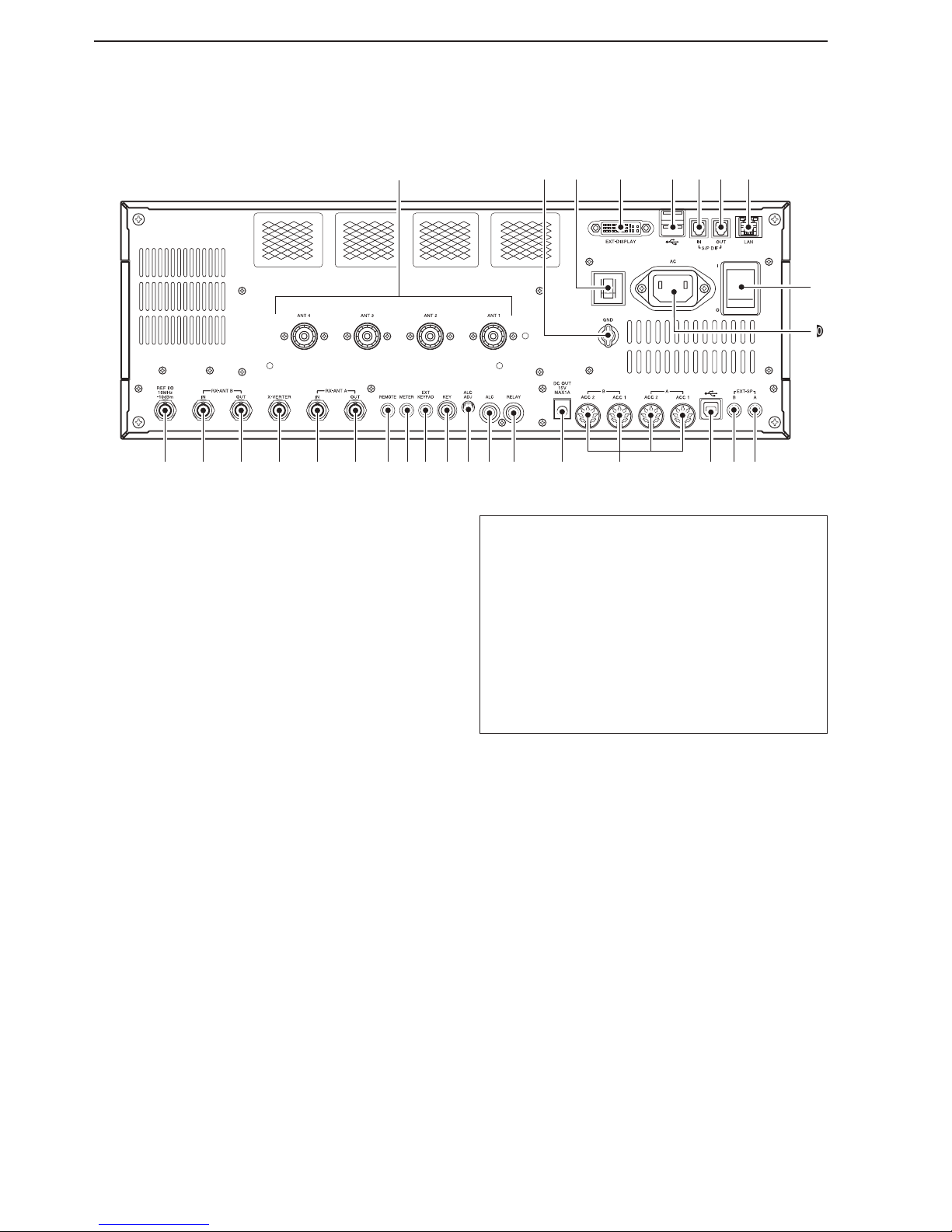
q ANTENNA CONNECTOR [ANT 1–4] (p. 3-4)
Connects to a 50 Ω antenna with a PL-259 plug
connector.
w GROUND TERMINAL [GND] (p. 3-2)
Connect this terminal to ground to prevent electrical
shocks, TVI, BCI and other problems.
e CIRCUIT BREAKER
Cuts off the AC input if excessive current flows.
r EXTERNAL DISPLAY TERMINAL [EXT-DISPLAY]
(p. 3-6)
Connects to an external display monitor.
• At least 800×600 pixel display is necessary.
t USB (Universal Serial Bus) PORT [USB A]
Insert a USB flash drive* for both reading and
storing a wide variety of the transceiver’s information and data.
• The indicator lights or blinks when the transceiver
reads or writes to the memory data.
• An unmount operation should be performed before
removing the USB flash drive*.
Connects to a PC keyboard for RTTY and PSK
operations.
• USB keyboards* are supported.
*: A USB flash drive or USB keyboard is not supplied
by Icom.
About the [USB A] connector:
• Supports only a USB ash drive, keyboard, mouse
or hub.
• Turn the transceiver power OFF when connecting
or disconnecting a USB keyboard, mouse or hub.
• DO NOT connect the following devices:
- Two or more of the same kind of USB devices.
(Example: Two USB hubs or two USB mice)
- A Multimedia adapter
- A USB HDD
- A USB flash drive larger than 32 GB
- A Bluetooth® keyboard or mouse.
y S/P DIF INPUT TERMINAL [S/P DIF– IN]
u S/P DIF OUTPUT TERMINAL [S/P DIF– OUT]
Connects to external equipment that supports S/P
DIF input/output.
i ETHERNET CONNECTOR [LAN] (p. 3-6)
Connects to a PC network through a LAN (Local
Area Network).
o MAIN POWER KEY [I/O] (p. 4-3)
Turns the internal power supply ON or OFF.
!0 AC POWER SOCKET [AC] (p. 3-4)
Connects the supplied AC power cable to an AC re-
ceptacle.
!1
EXTERNAL SPEAKER JACK MAIN [EXT-SP A]
(p. 3-5)
!2
EXTERNAL SPEAKER JACK SUB [EXT-SP B]
(p. 3-5)
Connects to an external speaker (4–8 Ω), if de-
sired.
L
B
q
!1!2!4 !3!5!6!7!8!9@0@1@2@3@4@5@6@7@8
r t y u i
o
!0
w e
Rear panel
1-13
1
PANEL DESCRIPTION
!3
USB PORT [USB B]
USB B type port connects to a PC.
• A USB A-USB B cable is required.
!4 ACCESSORY SOCKET [A ACC1]
ACCESSORY SOCKET [A ACC2]
ACCESSORY SOCKET [B ACC1]
ACCESSORY SOCKET [B ACC2]
Connects to external equipment such as a linear
amplifier, an automatic antenna selector/tuner, a
TNC for data communications, and so on.
• See page 20-2 for detailed socket information.
!5 DC OUTPUT JACK [DC OUT] (p. 20-5)
Outputs regulated 14 V DC (approximately) for ex-
ternal equipment. Connected in parallel with 13.8 V
outputs of [ACC 1] and [ACC 2]. (maximum 1 A in
total)
+
_
_
!6 T/R CONTROL JACK [RELAY] (pp. 3-5, 20-4)
Goes to ground when transmitting to control an ex-
ternal unit, such as a non-Icom linear amplifier.
NOTE: T/R control voltage and current must be
lower than 16 V DC/0.5 A (or 250 V AC,
200 mA with MOS-FET switching).
!7 ALC INPUT JACK [ALC] (p. 3-5)
Connects to the ALC output jack of a non-Icom lin-
ear amplifier.
!8 ALC LEVEL ADJUSTMENT POT [ALC ADJ]
Rotate to adjust the ALC levels.
No adjustment is required when the ALC output lev-
el of the connected non-Icom linear amplifier is 0 to
–4 V DC.
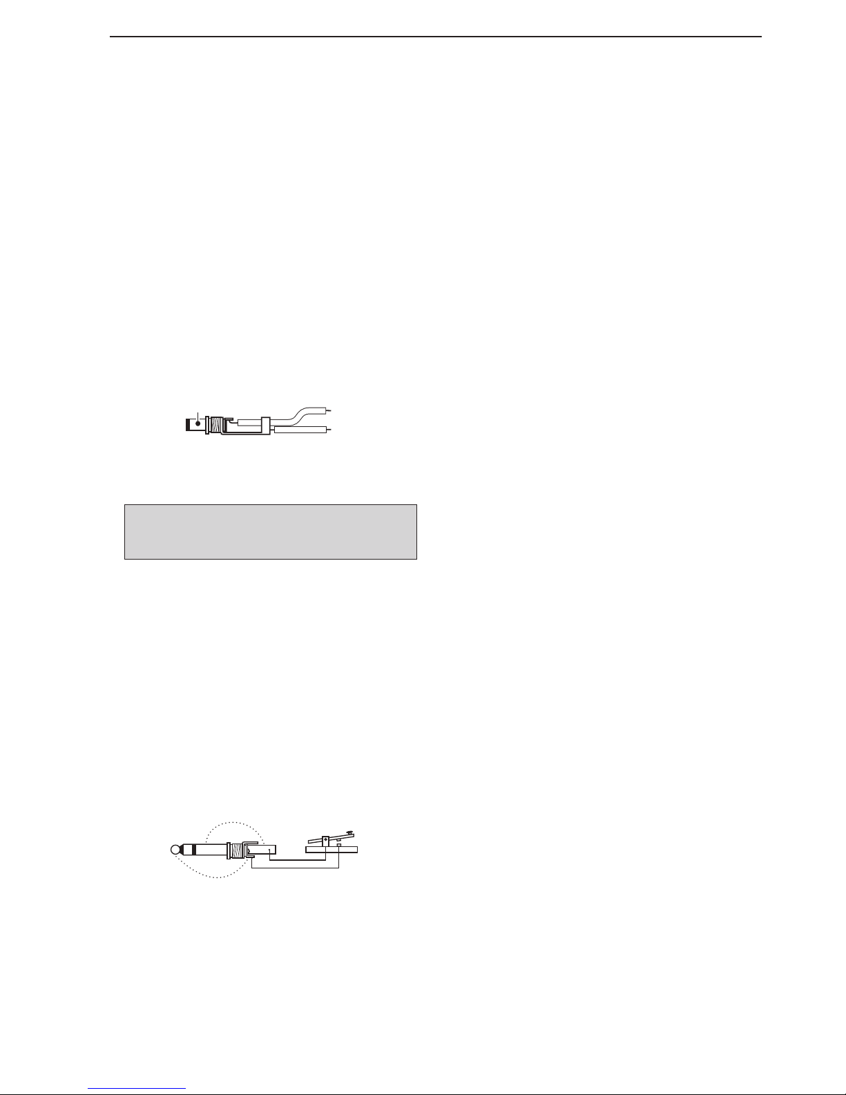
!9 STRAIGHT KEY JACK [KEY] (p. 20-3)
Connects to a straight key or external electronic
keyer with
1
⁄4 inch standard plug.
• [ELEC-KEY] on the front panel can be used for a straight
key or external electronic keyer. Deactivate the internal
electronic keyer in the Keyer set screen. (p. 5-13)
+
_
@0 EXTERNAL KEYPAD JACK [EXT KEYPAD]
(p. 20-4)
Connects to an external keypad for direct voice
memory (p. 9-11), memory keyer (p. 5-10), RTTY
memory (p. 5-17) or PSK memory (p. 5-29) transmission.
A transceiver mute control line (both transmit and
receive) is also supported.
@1 METER JACK [METER] (p. 20-5)
Outputs the received signal strength, transmit out-
put power, VSWR, ALC, speech compression, V
d or
Id levels for an external meter.
@2 CI-V REMOTE CONTROL JACK [REMOTE]
(p. 20-5)
Connects to a PC through the optional CT-17
c i -v
l e v e l c o n v e r t e r for external control of the trans-
ceiver.
Used for transceive operation with another Icom
CI-V transceiver or receiver.
@3 RECEIVE ANTENNA A OUT [RX ANT A– OUT]
@4 RECEIVE ANTENNA A IN [RX ANT A– IN]
Located between the transmit/receive switching cir-
cuit and the receiver’s RF stage in the Sub band
(Main band in the split frequency mode).
Connects to an external unit, such as preamplifier
or RF filter, using BNC connectors, if desired.
When no external unit is connected, [RX ANT A–
IN] and [RX ANT A– OUT] must be deactivated
and internally shorted by the switching relay. This
setting is available in the ANT screen. (p. 13-6)
@5 TRANSVERTER CONNECTOR [X-VERTER]
(p. 20-4)
Connects to an external transverter for input/out-
put.
Activated by a voltage applied to [ACC 2] pin 6, or
when the transverter function is in use. (pp. 20-2,
15-14)
@6 RECEIVE ANTENNA B OUT [RX ANT B– OUT]
@7 RECEIVE ANTENNA B IN [RX ANT B– IN]
Located between the transmit/receive switching cir-
cuit and receiver’s RF stage in the Main band (Sub
band during split operation).
Connects an external unit, such as preamplifier or
RF filter, using BNC connectors, if desired.
When no external unit is connected, [RX ANT B–
IN] and [RX ANT B– OUT] must be deactivated
and internally shorted by the switching relay. This
setting is available in the ANT screen. (p. 13-6)
@8 REFERENCE SIGNAL INPUT/OUTPUT
TERMINAL [REF I/O]
Input or output for a 10 MHz reference signal.

1-14
1
PANEL DESCRIPTION
q BAND WIDTH INDICATOR (p. 7-5)
Displays the passband width of the IF filter.
w MODE INDICATOR
Displays the selected mode.
e SHIFT FREQUENCY INDICATOR (p. 7-5)
Displays the shift frequency of the IF filter.
r PASSBAND WIDTH INDICATOR (p. 7-5)
Graphically displays the passband width for twin
PBT operation and the center frequency for IF shift
operation.
t QUICK TUNING INDICATOR (p. 4-7)
Appears when the Quick Tuning step function is ON.
y BANDPASS FILTER INDICATOR
Appears when the narrow filter (500 Hz or less) is
selected in the CW, RTTY, or PSK mode.
u RTTY TUNING INDICATOR
Displays the tuning level in the RTTY mode.
i CLOCK READOUT
Displays the current time.
o FREQUENCY READOUTS
Displays the operating frequency.
• Gray characters are used for a non-active frequency.
!0 IF FILTER INDICATOR
Displays the selected IF filter number.
!1 VFO/MEMORY CHANNEL INDICATOR (p. 4-5)
Indicates the VFO mode or selected memory chan-
nel number.
!2 TX ICON
“
TX
” appears while transmitting.
Indicates the frequency used for transmit.
• Displays on the Sub readout when the split function
is turned ON.
• A TX icon with doted rectangle, “
TX
” is displayed,
instead of the regular “
TX
” TX icon, when a frequency outside of an amateur band frequency range
is selected. This function can be turned OFF in the
Others set screen, if desired. (p. 4-5)
!3 S/RF METER (p. 4-11)
Displays the signal strength while receiving. Dis-
plays the relative output power, SWR, ALC or compression levels while transmitting.
Display
qw wt
!3
!2
o
!1
!0
e er ry yu uiq
t
 Loading...