


INSTRUCTION MANUAL
HF/50 MHz
ALL MODE TRANSCEIVER
i703
FOREWORD
Thank We understand that you have a choice of many different radios in the market place. We want to take a couple of moments of your time to thank you for making the IC-703 your radio of choice, and hope you agree with Icom’s philosophy of “technology first.” Many hours of research and development went into the design of your IC-703.
FEATURES
DSP features (AF DSP; UT-106 DSP UNIT required some version)
All mode capability covering 160–6 m
9.0–15.87 V operation
Compact with detachable front panel
±0.5 ppm of high frequency stability
Built in antenna tuner
Simple band scope function
IMPORTANT
READ THIS INSTRUCTION MANUAL CAREFULLY before attempting to operate the transceiver.
SAVE THIS INSTRUCTION MANUAL. This manual contains important safety and operating instructions for the IC-703.
EXPLICIT DEFINITIONS
WORD |
DEFINITION |
|
|
Personal injury, fire hazard or electric RWARNING shock may occur.
CAUTION Equipment damage may occur.
If disregarded, inconvenience only. No NOTE risk or personal injury, fire or electric
shock.
PRECAUTION
RWARNING RF EXPOSURE! This device emits Radio Frequency (RF) energy. Extreme caution should be observed when operating this device. If you have any questions regarding RF exposure and safety standards please refer to the Federal Communications Commission Office of Engineering and Technology’s report on Evaluating Compliance with FCC Guidelines for Human Radio Frequency Electromagnetic Fields (OET Bulletin 65).
RWARNING HIGH VOLTAGE! NEVER attach an antenna or internal antenna connector during transmission. This may result in an electrical shock or burn.
RNEVER apply AC to the [DC13.8V] receptacle on the transceiver rear panel. This could cause a fire or damage the transceiver.
RNEVER apply more than 16 V DC, such as a 24 V battery, to the [DC13.8V] receptacle on the transceiver rear panel. This could cause a fire or damage the transceiver.
RNEVER let metal, wire or other objects touch any internal part or connectors on the rear panel of the transceiver. This may result in an electric shock.
NEVER expose the transceiver to rain, snow or any liquids.
AVOID using or placing the transceiver in areas with temperatures below –10°C (+14°F) or above +60°C (+140°F). Be aware that temperatures on a vehicle’s dashboard can exceed 80°C (+176°F), resulting in permanent damage to the transceiver if left there for extended periods.
AVOID placing the transceiver in excessively dusty environments or in direct sunlight.
i
AVOID placing the transceiver against walls or putting anything on top of the transceiver. This will obstruct heat dissipation.
Place unit in a secure place to avoid inadvertent use by children.
During mobile operation, DO NOT operate the transceiver without running the vehicle’s engine. When the transceiver’s power is ON and your vehicle’s engine is OFF, the vehicle’s battery will soon become exhausted.
Make sure the transceiver power is OFF before starting the vehicle. This will avoid possible damage to the transceiver by ignition voltage spikes.
During maritime mobile operation, keep the transceiver and microphone as far away as possible from the magnetic navigation compass to prevent erroneous indications.
BE CAREFUL! The rear panel will become hot when operating the transceiver continuously for long periods.
BE CAREFUL! If a linear amplifier is connected, set the transceiver’s RF output power to less than the linear amplifier’s maximum input level, otherwise, the linear amplifier will be damaged.
Use Icom microphones only (supplied or optional). Other manufacturer’s microphones have different pin assignments, and connection to the IC-703 may damage the transceiver.
Beat signals may be heard on some frequencies. These will occur as a result of circuit construction.
For U.S.A. only
Caution: Changes or modifications to this transceiver, not expressly approved by Icom Inc., could void your authority to operate this transceiver under FCC regulations.
FOREWORD …………………………………………… i IMPORTANT ……………………………………………i
EXPLICIT DEFINITIONS ……………………………… i PRECAUTION …………………………………………i
TABLE OF CONTENTS ……………………………… ii
QUICK REFERENCE GUIDE ……………… I–X
■Installation ………………………………………… I
1.Grounding your Shack ……………………… I
2. Installing your DC Power Supply ………… I
3.Installing lightning protection ……………… II
4.Installing your antenna system …………… II
5.Connect other peripheral equipment …… III
■Operation ………………………………………… III
1.Voice ………………………………………… III
2.CW…………………………………………… III
3.Other convenient items …………………… IV
■Your first contact ………………………………… IV D Getting started ………………………………… IV D Just listening …………………………………… V
1.Select the desired band …………………… V
2.Tune to the desired frequency …………… V
3.Adjust audio output ………………………… V D What are you hearing? ……………………… VI
1.Verify mode ………………………………… VI
2.Reducing interference (Some functions may require
an optioanl unit depending on version) … VI
■Ready to call CQ? ……………………………… IX
1.Setting up your Mic Gain ………………… IX
2.Speech compressor………………………… X
TABLE OF CONTENTS
1 PANEL DESCRIPTION ………………… 1–10
■Front panel ………………………………………… 1
■Multi-function switches …………………………… 4 DM1 functions …………………………………… 4 DM2 functions …………………………………… 4 DM3 functions …………………………………… 4 DM4 functions …………………………………… 5 DS1 functions …………………………………… 6 DS2 functions …………………………………… 6 DS3 functions …………………………………… 6 DS4 functions
(UT-106 is required for some version) ……… 6
■Rear panel ………………………………………… 7 DDATA socket …………………………………… 8 DACC socket……………………………………… 8
■Function display…………………………………… 9
■Microphone (HM-103) ………………………… 10
2 INSTALLATION AND CONNECTIONS … 11–16
■Unpacking………………………………………… 11
■Selecting a location……………………………… 11
■Grounding………………………………………… 11
■Antenna connection……………………………… 11
■Installation ……………………………………… 12 DSingle body mounting ………………………… 12 DStand …………………………………………… 12 DFront panel separation ……………………… 12 DFront panel mounting ………………………… 12
■Required connections…………………………… 13
■Advanced connections ………………………… 14
■DC Power voltage ……………………………… 15
■DC Power supply connections ………………… 15
■Battery connections …………………………… 15
■External antenna tuners and linear amplifier … 16
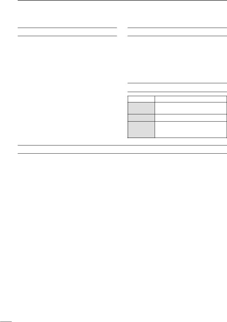
SUPPLIED ACCESSORIES
The transceiver comes with the following accessories.
|
|
Qty. |
q Hand microphone (HM-103) .............................. |
1 |
|
w DC power cable (OPC-1229) ............................. |
1 |
|
e Spare fuse (FGB 4 A) ........................................ |
3 |
|
r ACC cable ........................................................... |
1 |
|
t 3.5 |
(d) mm plug ................................................... |
1 |
y 6.5 |
(d) mm Electronic keyer plug......................... |
1 |
u Microphone hanger.............................................. |
1 |
|
q |
|
|
|
|
|
|
|
|
|
|
|
|
|
|
w |
|
|
|
|
|
|
|
|
|
|
|
|
|
|
|
|
e |
|
|
|
|
|
r |
t y u |
|||||||||||
|
|
|
|
|
|
|
|
|
|
|
|
|
|
|
|
|
|
|
|
|
|
|
|
|
|
|
|
|
|
|
|
|
|
|
|
|
|
|
|
|
|
|
|
|
|
|
|
|
|
|
|
|
|
|
|
|
|
|
|
|
|
|
|
|
|
|
|
|
|
|
|
|
|
|
|
Icom, Icom Inc. and the 
 logo are registered trademarks of Icom Incorporated (Japan) in the United States, the United Kingdom, Germany, France, Spain, Russia and/or other countries.
Quick Reference
1
2
3
4
5
6
7
8
9
10
11
12
13
14
15
16
17
18
19
ii

TABLE OF CONTENTS
3 BASIC OPERATION ……………………17–26
■When first applying power (CPU resetting)…… 17 DM1 display selection ………………………… 17
■Initial settings …………………………………… 17
■VFO description ………………………………… 18 DThe differences between VFO and
memory mode ………………………………… 18
■Frequency setting ……………………………… 19
■Operating mode selection ……………………… 23
■Volume setting …………………………………… 23
■Squelch and receive (RF) sensitivity ………… 24
■Dial lock function ………………………………… 25
■Basic transmit operation ……………………… 25 DTransmitting …………………………………… 25 DMaximum output power ……………………… 25 DSetting output power ………………………… 26 DSetting microphone gain……………………… 26
4 RECEIVE AND TRANSMIT …………… 27–45
■Operating SSB…………………………………… 27 DConvenient functions for receive …………… 27 DConvenient functions for transmit …………… 27
■Operating CW …………………………………… 28 DConnections for CW ………………………… 28 DCW operation ………………………………… 29 DConvenient functions for receive …………… 30 DConvenient functions for transmit …………… 30 DCW reverse mode …………………………… 30 DCW pitch control ……………………………… 31 DElectronic CW keyer ………………………… 31 DCW side tone function………………………… 32 DKeyer set mode ……………………………… 32
■Memory keyer functions………………………… 33 DMemory keyer send menu …………………… 34 DEditing a memory keyer ……………………… 35 DContest number set mode …………………… 36 DMemory keyer set mode……………………… 37
■Operating RTTY ………………………………… 38 DConnections for RTTY (FSK)………………… 38 DRTTY (FSK) operation ……………………… 38 DConvenient functions for receive …………… 39 DRTTY reverse mode ………………………… 39 DPresetting for RTTY ………………………… 40 DRTTY tone set mode ………………………… 40
■Operating AM …………………………………… 41 DConvenient functions for receive …………… 41 DConvenient functions for transmit …………… 41
■Operating FM …………………………………… 42 DConvenient functions for receive …………… 42 DConvenient functions for transmit …………… 42 DTone squelch operation ……………………… 43 DTone scan operation ………………………… 43 DFM tone set mode …………………………… 44
■Repeater operation ……………………………… 45
5 FUNCTION FOR RECEIVE …………… 46–50
■Simple band scope ……………………………… 46
■Preamp and attenuator ………………………… 46
■RIT function ……………………………………… 47
■IF shift function ………………………………… 47
■Noise blanker …………………………………… 48
DNoise blanker level set mode ……………… 48
■AGC time constant ……………………………… 48
■Optional filter selection ………………………… 49
■Peak meter hold ………………………………… 50
■DSP Functions (may require an optional unit depending on version) ………………………… 50 DANF (Automatic Notch Filter) function ……… 50 DNR (Noise Reduction) function ……………… 50
6 FUNCTION FOR TRANSMIT …………… 51–55
■Split frequency operation ……………………… 51 DQuick split function …………………………… 52
■Meter selection ………………………………… 52
■VOX operation …………………………………… 53 DVOX set mode ………………………………… 53
■Speech compressor …………………………… 54 DCompression level set mode ………………… 54
■SWR………………………………………………… 55 DMeasuring SWR ……………………………… 55
7 MEMORY OPERATION ………………… 56–60
■Memory channels ……………………………… 56
■Memory channel selection……………………… 56
■Memory programming ………………………… 57
■Memory clearing ………………………………… 58
■Frequency transferring ………………………… 58
■Memory names ………………………………… 59
■Memo pads ……………………………………… 60
8 SCAN OPERATION …………………… 61–63
■Scan types ……………………………………… 61
■Preparation ……………………………………… 61
■Programmed scan operation…………………… 62
■Memory scan operation ………………………… 62
■Select memory scan operation ………………… 63
■Priority watch …………………………………… 63
9 ANTENNA TUNER OPERATION……… 64–66
■Antenna tuner operation ……………………… 64 DInternal antenna tuner………………………… 64 DTuner operation ……………………………… 64 DOptional external tuner operation …………… 65 DOptional AT-180
AUTOMATIC ANTENNA TUNER operation ……… 65
DOptional AH-4
AUTOMATIC ANTENNA TUNER operation ……… 66
iii

TABLE OF CONTENTS
10 DATA COMMUNICATION …………… 67–70 |
29 [UP]/[DN] speed ………………………… 80 |
|
■Connections for packet ………………………… 67 |
30 Noise blanker in AM mode ……………… 80 |
|
DWhen connecting to [DATA] socket ………… 67 |
31 Available memo pads …………………… 80 |
|
DWhen connecting to [ACC] socket ………… 67 |
32 Power ON check function ……………… 81 |
|
DWhen connecting to [MIC] connector ……… 67 |
33 Auto tune start function ………………… 81 |
|
■Packet (AFSK) operation ……………………… 68 |
34 PTT tune function ………………………… 81 |
|
DFrequency indication during AFSK operation … 68 |
35 Tuner switch condition …………………… 81 |
|
DSSB-D mode selection ……………………… 69 |
36 Packet data speed ……………………… 81 |
|
DCarrier point setting…………………………… 69 |
37 Voice synthesizer language……………… 82 |
|
DAdjusting the transmit signal from the TNC… 70 |
38 Voice synthesizer speed ………………… 82 |
|
11 CONTROL COMMAND ……………… 71–73 |
39 S-meter level speech …………………… 82 |
|
40 CI-V address setting ……………………… 82 |
||
■Remote jack (CI-V) information ……………… 71 |
41 CI-V data transffer rate…………………… 82 |
|
DCI-V connection example ……………………… 71 |
42 CI-V transceive …………………………… 82 |
|
DData format ……………………………………… 71 |
43 CI-V operating frequency data length … 82 |
|
DCommand table ……………………………… 72 |
13 MAINTENANCE …………………………… 83 |
|
D Band stacking register ……………………… 73 |
||
■Fuse replacement ……………………………… 83 |
||
D Codes for memory keyer contents ………… 73 |
||
D Codes for memory name contents ………… 73 |
■Memory backup ………………………………… 83 |
|
12 SET MODE …………………………… 74–82 |
■Cleaning ………………………………………… 83 |
|
14 TROUBLESHOOTING………………… 84–85 |
||
■General …………………………………………… 74 |
||
|
||
DQuick set mode operation …………………… 74 |
15 OPTIONAL UNIT |
|
DInitial set mode operation …………………… 74 |
||
INSTALLATIONS AND SETTINGS … 86–89 |
||
■Quick set mode items…………………………… 75 |
||
■Opening the transceiver case ………………… 86 |
||
■Initial set mode items …………………………… 76 |
||
■UT-102 VOICE SYNTHESIZER UNIT ……………… 86 |
||
1 Maximum output power setting ………… 76 |
||
DOperation ……………………………………… 86 |
||
2 Power save setting ……………………… 76 |
||
■IF filter …………………………………………… 87 |
||
3 Simple mode setting ……………………… 76 |
||
■UT-106 DSP RECEIVER UNIT …………………… 88 |
||
4 Mode availability ………………………… 76 |
||
■MB-72 CARRYING HANDLE ……………………… 88 |
||
5 Output power setting for mode ………… 76 |
||
■AT-180 internal switch description …………… 89 |
||
6 Confirmation beeps ……………………… 77 |
||
|
||
7 Band edges beeps ……………………… 77 |
16 SPECIFICATIONS ………………………… 90 |
|
8 Beep level adjustment …………………… 77 |
||
■General …………………………………………… 90 |
||
9 Beep audio level limit …………………… 77 |
||
■Transmitter ……………………………………… 90 |
||
10 CW carrier point setting ………………… 77 |
||
■Receiver ………………………………………… 90 |
||
11 CW side tone level ……………………… 77 |
||
■Antenna tuner …………………………………… 90 |
||
12 CW side tone level limit ………………… 77 |
||
|
||
13 SSB/CW frequency shift setting ………… 78 |
17 OPTIONS ……………………………… 91–92 |
|
14 Display backlighting ……………………… 78 |
18 MENU GUIDE ………………………… 93–94 |
|
15 Key/switch backlighting ………………… 78 |
||
16 Light timer setting ………………………… 78 |
19 ABOUT CE……………………………… 95–96 |
|
17 LED brightness …………………………… 78 |
||
18 Automatic power OFF …………………… 78 |
|
|
19 Current intercept point …………………… 79 |
|
|
20 RF gain/squelch control ………………… 79 |
|
|
21 Sub dial setting …………………………… 79 |
|
|
22 Optional filter selection…………………… 79 |
|
|
23 Peak meter hold setting ………………… 79 |
|
|
24 Quick split function ……………………… 79 |
|
|
25 Split lock function ………………………… 80 |
|
|
26 Split offset frequency …………………… 80 |
|
|
27 Scan resume condition…………………… 80 |
|
|
28 Scanning speed…………………………… 80 |
|
Quick Reference
1
2
3
4
5
6
7
8
9
10
11
12
13
14
15
16
17
18
19
iv
QUICK REFERENCE GUIDE
■ Installation
1.Install a ground system for DC noise suppression and RFI suppression
2.Install your DC power supply
3.Install lightning protection. This will help protect more than your gear.
4.Install and connect an antenna system for the appropriate bands of operation
5.Connect other peripheral equipment. This includes microphones, headsets, TNC, amplifiers and any other equipment necessary to make your shack complete.
1. Grounding your Shack
Although your radio will operate by connecting the DC power supply and antenna, it is necessary to have a good ground system in your shack. A ground connection is the electrical contact between the common point of an electrical or electronic system and the earth.
A good earth ground is necessary to prevent electrical shock, eliminate problems from RFI and DC noise. With more electronic devices being used today, it is also important to reduce RFI and EMI. Although you may not see interference in your shack, without a grounding system, your neighbours may experience interference. Even though many of these devices are Part 15, where they must accept interference from their surrounding environment, it is best to eliminate as much of the possible interference from your shack.
If you do not have a grounding system for your shack, depending on the location of your shack, basement or ground floor, a good ground system can be as simple as a couple of ground rods driven 6 to 8 feet into the soil. When installing your IC-703 to your grounding system, the shortest most direct connection is recommended.
 NOTE: There are many publications covering
  proper grounding techniques. Check with your local
  dealer for more information and recommendations.
 RWARNING!: NEVER ground station equip-
  ment or antennas to house gas lines. NEVER at-
  tach ground lines to plastic (pvc) pipe.
D Some Symptoms if inadequate grounding a. Poor DC Ground
50/60 Hz hum on the audio either Rx or Tx without the antenna connected.
If you feel a tingling sensation when you touch a metal surface. Surfaces such as the cover of your radio or power supply.
b. Poor RF Ground
While transmitting and you feel a tingling sensation when you touch a metal surface. Surfaces such as the cover of your radio or power supply.
While transmitting, you experience interference to other electronic devices, such as the telephone, television or stereo audio systems.
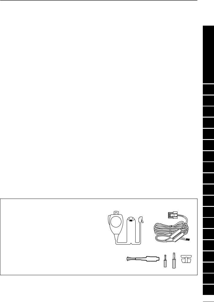
2. Installing your DC Power Supply
The DC power supply is a device used to convert 110/220 V AC, also know as Household current, to a steady source of 13.8 V DC.
The perfect match to your IC-703 is the PS-125. This plug and play unit plugs into the DC power receptacle using an optional OPC-1248 located on the rear of the radio.
Or connect the supplied DC power cable (OPC-1229) to the appropriate color coded terminals, then insert the DC connector into the DC power receptacle located on the rear of the radio.
 NOTE: Although the power supply current require-
ment is quite low during receiving, this not the case
 when you transmit. With many electrical devices in
  the shack, it is very important to verify the electrical
  circuit is not overloaded.
I
|
|
Transceiver |
|
Ground |
|
AC |
|
|
to DC |
||
PS-125 |
outlet |
||
power |
A DC power |
||
|
|||
|
receptacle |
supply* |
|
|
|
Black Red |
|
|
|
_ + |
|
|
*13.8 V; |
|
|
|
at least 3.0 A |
||
|
continuous |
AC cable |
|
DC power cable |
|
||
|
|
||
Optional |
Supplied |
|
|
OPC-1248 |
OPC-1229 |
||
Connect to an AC outlet |
4 A fuses |
|
using the supplied AC cable. |
||
|
QUICK REFERENCE GUIDE
3. Installing lightning protection
Although you may not live in an area with high occur- |
NOTE: There are many publications covering |
rence for lightning storms, it is always wise to take |
proper lightning protection, check with your local |
precautions for lightning or static discharges. Proper |
dealer for more information and recommendations. |
lightning protection not only offers protection to the |
|
ham gear, but the shack and most importantly the op- |
|
erator. |
|
|
|
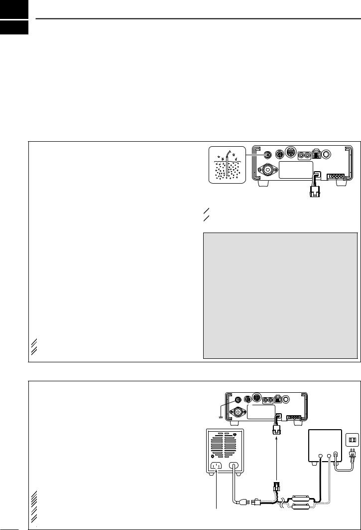
4. Installing your antenna system
Whether your IC-703 is your first radio or one of many, one of your key elements in a great shack is the antenna system. There is a connection on the back of your IC-703, for HF and 6 m. If you are using one antenna for HF and 6 m, for simplicity, connect the antenna coax to ANT.
ANTENNA
Connect a HF/50MHz antenna
Impedance: 50Ω
Your IC-703 is equipped with an internal antenna tuner (ATU) for operation on 160–6 m. This ATU is designed to work with an unbalanced 50 Ω feedline. The purpose of the internal antenna tuner is to match the impedance of your antenna system to as close to a 50 Ω load as possible. This ATU will not operate with a long wire or ladder line (450 Ω or other balanced feedlines). An external ATU such as the AH-4 would be necessary for this kind of operation.
PL-259 CONNECTOR INSTALLATION EXAMPLE
q |
|
30 mm |
|
|
|||||||
|
|
|
|
|
|
|
|
|
|
|
|
|
|
|
|
|
|
|
|
|
|
|
|
|
|
|
|
|
|
|
|
|
|
|
|
|
|
|
|
|
|
|
|
|
|
||
|
|
|
|
|
|
|
|
|
|
|
|
Coupling ring |
10 mm (soft solder) |
||||||||||
w |
10 mm |
Soft |
|||||||||
|
|
|
|
|
|
|
|||||
|
|
|
|
|
|
|
solder |
||||
|
|
|
|
|
|
|
|
|
|
|
|
|
|
|
|
|
|
|
|
|
|
|
|
|
|
|
|
|
|
|
|
|
|
|
|
|
|
|
|
|
1–2 mm |
||||||
e |
|
solder solder |
|||||||||
|
|
|
|
|
|
|
|
||||
|
|
|
|
|
|
|
|
|
|
|
|
r
Slide the coupling ring down. Strip the cable jacket and soft solder.
Strip the cable as shown at left. Soft solder the center conductor.
Slide the connector body on and solder it.
Screw the coupling ring onto the connector body.
30 mm ≈ 9⁄8 in 10 mm ≈ 3⁄8 in 1–2 mm ≈ 1⁄16 in
 RWARNING: Although a mag mount antenna
works great on a vehicle, DO NOT use the IC-703
 with this type of antenna.
 CAUTION: Although your IC-703 has protection to
drop down power with a high SWR, this does not
 completely protect the transceiver from transmis-
sion without an antenna. Make sure you have an
 antenna connected whenever you transmit with
 your radio.
 NOTE: There are many publications covering
proper antennas and their installation, check with
 your local dealer for more information and recom-
  mendations.
Antenna SWR
Each antenna is tuned for a specified frequency range and SWR may be increased out-of-range. When the SWR is higher than approx. 2.0:1, the transceiver’s power drops to protect the final transistors. In this case, an antenna tuner is useful to match the transceiver and antenna. Low SWR allows full power for transmitting even when using the antenna tuner. The IC-703 has an SWR meter to monitor the antenna SWR continuously.
Quick Reference
II
QUICK REFERENCE GUIDE
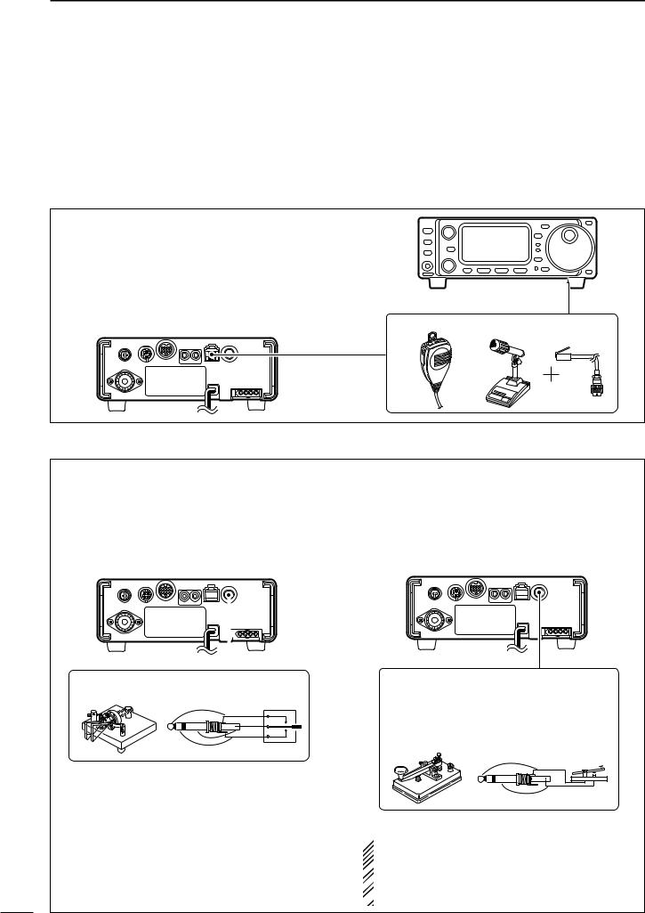
5. Connect other peripheral equipment
Everyone has his or her favorite ad-on gear; now is |
If you do not see the particular item you are wanting |
the time to connect this gear! We will cover the basic |
to connect, refer to the Advance Connections section |
devices that can be connected to your IC-703. |
starting on page 14. |
|
|
■ Operation
1. Voice
Microphones: Connect the microphone to the modu- lar-type connector bottom of the front panel or back of the radio.
Front panel
Rear panel |
MICROPHONES |
|
HM-103 |
SM-20 OPC-589 |
2. CW
CW Key: There are several types of keys or keyers that can be used with your IC-703.
a.Iambic Key paddle: Use a 6.35(d) mm (1⁄4″) stereo plug and connect to the [KEY] jack located on the rear of the radio.
b.Straight Key: Use a 6.35(d) mm (1⁄4″) mono plug and connect key to the back of the radio.
c.External Keyer: Use a 6.35(d) mm (1⁄4″) mono plug and connect to the back of the radio.
d.Computer Keying: Use a 6.35(d) mm (1⁄4″) mono plug and connect to the back of the radio.
Rear panel |
|
Rear panel |
|
||||||||
|
|
|
|
|
|
|
|
|
|
|
|
|
|
|
|
|
|
|
|
|
|
|
|
|
|
|
|
|
|
|
|
|
|
|
|
|
|
|
|
|
|
|
|
|
|
|
|
|
|
|
|
|
|
|
|
|
|
|
|
CW KEY
When connecting a paddle
(dot)
(com)
(dash)
CW KEY
A straight key can be used when the internal electronic keyer is turned OFF in keyer set mode. (p. 32)
When connecting a straight key or else
(+)
(_)
 NOTE: You will need to select the type of keyer you
are using in the keyer set mode. There are many
 advanced CW functions in this set mode. Until you
  have a full understanding of these functions
  change only the items necessary.
III
QUICK REFERENCE GUIDE
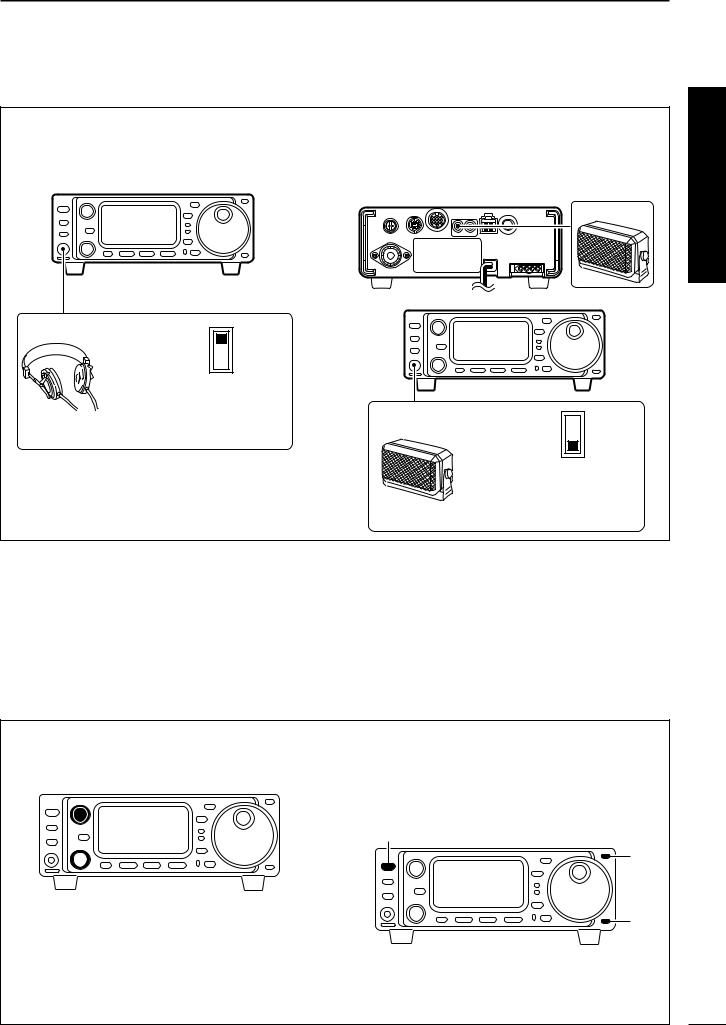
3. Other convenient items
Headphones:
A 3.5(d) mm (1⁄4″) mono jack for operation without using the internal or external speakers. Perfect for operation without disturbing others in the room.
Front panel
HEADPHONES
PHONES ∫
SPEAKER √
Select ‘PHONES’ with the [PHONES/SPEAKER] switch on the back of the front panel.
External Speaker:
A 3.5(d) mm (1⁄8″) mono jack for operation with an external speaker. (Input impedance: 8 Ω/Max. input power: 5 W)
Rear panel
SPEAKER
or
Front panel
SPEAKER
PHONES ∫
SPEAKER √
Select ‘SPEAKER’ with the [PHONES/SPEAKER] switch on the back of the front panel.
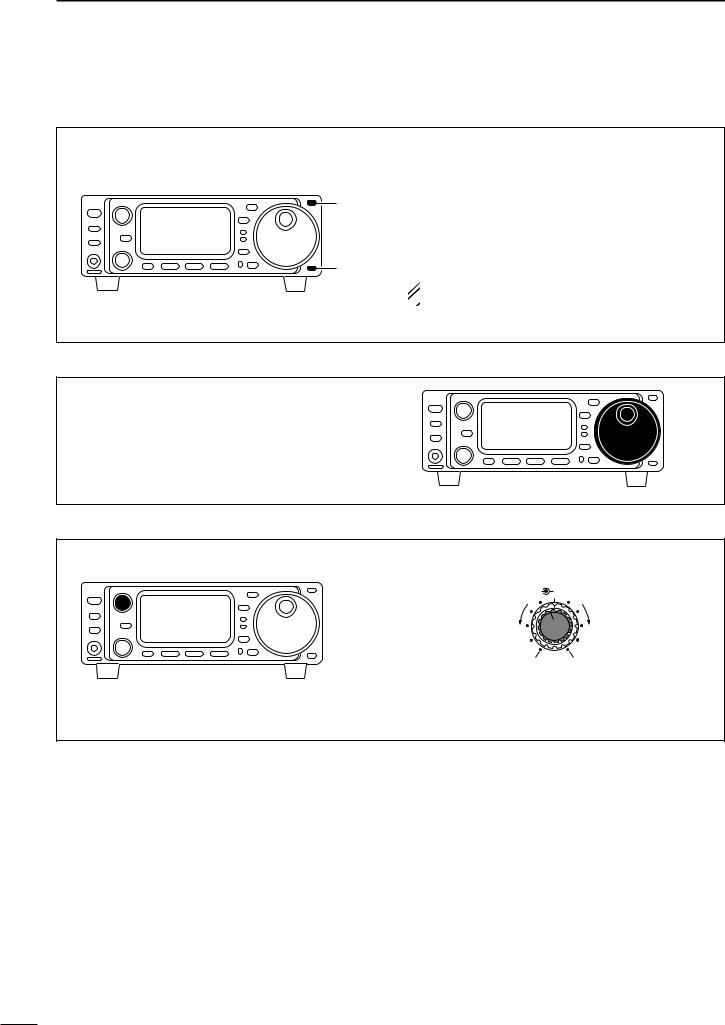
■ Your first contact
Now you should have your IC-703 installed in your shack, and like a kid on his birthday, you are probably excited to get on the air. We would like to take you through a few basic operation steps to make your first “On The Air” an enjoyable experience.
DGetting started
1.Before powering up your radio, you may want to make sure the following controls are set in the following positions:
• [AF] |
: Commonly referred to as the vol- |
|
ume: fully counter clockwise. |
• [RF/SQL] |
: The control for the RF Gain and |
|
Squelch circuits: 12 o’clock. |
• [SHIFT] |
: Shifts the IF center frequency: |
|
12 o’clock |
2.Resetting the CPU: Although you have purchased a brand new radio, some settings may be changed from the factory defaults during the QC process. So your radio can start from Factory Defaults resetting the CPU is necessary. (Refer to p.17)
[POWER]
[Y]
[Z]
Quick Reference
IV
QUICK REFERENCE GUIDE
DJust listening
1. Select the desired band
On your IC-703, an easy way of changing bands is by using the [(Y)BAND] or [(Z)BAND] located just right corner on the front panel.
Push [(Y)BAND] or [(Z)BAND] to select the desired band.
•Pushing [(Y)BAND] or [(Z)BAND] continuously scrolls through the available bands.
[Y]
[Z]
•Say you want to go to 20 meters or 14 MHz; you would push [(Y)BAND] or [(Z)BAND] several times to select it. This will change the displayed operating frequency to the 20-meter band.
 NOTE: The band stacking register can also be
  used to select bands. (Refer to p. 22)
2. Tune to the desired frequency
Directly left of the [(Y)BAND]/[(Z)BAND] is the main dial. This will allow you to dial in the frequency you want to operate. You will notice the tuning speed [TS] is 10 Hz resolution. Page 20 will instruct you on how to set the tuning speed [TS] for 1 Hz resolution.
3. Adjust audio output
Adjust this control to a comfortable audio level.
AF |
RF/SQL |
Decreases |
Increases |
No audio output |
Max. audio output |
V
QUICK REFERENCE GUIDE
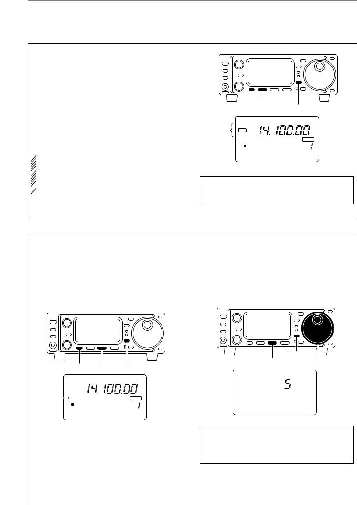
DWhat are you hearing?
Stop and focus on what you are hearing. Do you hear a lot of noise? Is the signal intelligible? Are you set up for the right mode? How about the filters?
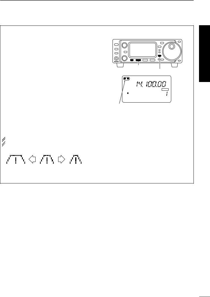
1. Verify mode
Although your IC-703 will automatically select USB or
MODE
LSB in the HF bands, it will not select any of the other modes. You will need to select the proper mode whether CW, RTTY, AM or FM.
Hint!
The Band Stacking Register will memorize the last frequency used in the band, as well as the Mode, Filter, Tuner and AGC settings. This makes band hoping much easier.
2. Reducing interference (some functions may require an optional unit depending on version)
Your IC-703 has many features to reduce QRM and QRN from the desired signal.
a.Noise Reduction: The noise reduction system on your IC-703 is part of the DSP. This is used to reduce the hiss and QRM levels.
qSelect S4 (DSP menu).
•Push [DISPLAY] once or twice to select S. •Push [MENU] one or more times to select S4.
wPush [(F-2)NR] to activate the noise reduction function.
•“DSP” and “NR” appear when the function is ON.
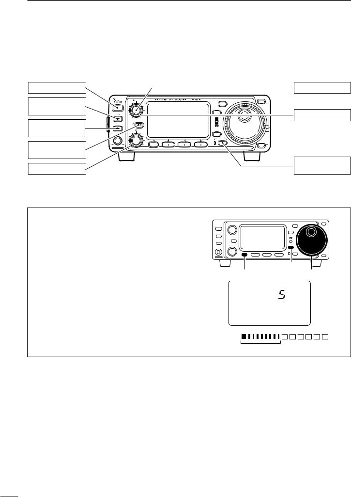
b.Adjusting the Noise Reduction: The noise reduction is completely variable on how much of the DSP Noise Reduction is used.
qPush [(F-3)NRL] to indicate the noise reduction level.
wRotate the [M-CH] control to set the noise reduction level.
ePush [(F-3)NRL] to exit the noise reduction level set mode.
Quick Reference
[MENU] |
[(F-2)] [DISPLAY] |
[M-CH] |
[(F-3)] |
USB
DSP
Appear
NR
|
|
|
BLANK |
S1 3 5 7 9 |
20 |
40 60dB |
VFO A |
PO |
5 |
10 |
CH |
S4 ANF NR NRL
Noise reduction ON
Noise reduction OFF
USB
DSP
NR
|
|
|
BLANK |
S1 3 5 7 9 |
20 |
40 60dB |
VFO A |
PO |
5 |
10 |
CH |
S4 LEVEL 4 NRL
Hint!
How far you advance the NR control will determine how much the noise can be effectively reduced. Adjusting the noise reduction level too high may cause some distortion to occur on the received signal. The noise reduction level should only be set as high as is necessary. Use this setting, along with RF gain, NB (noise blanker, if needed), and IF filters as well, to minimize the effects of noise on the target signal.
VI
QUICK REFERENCE GUIDE
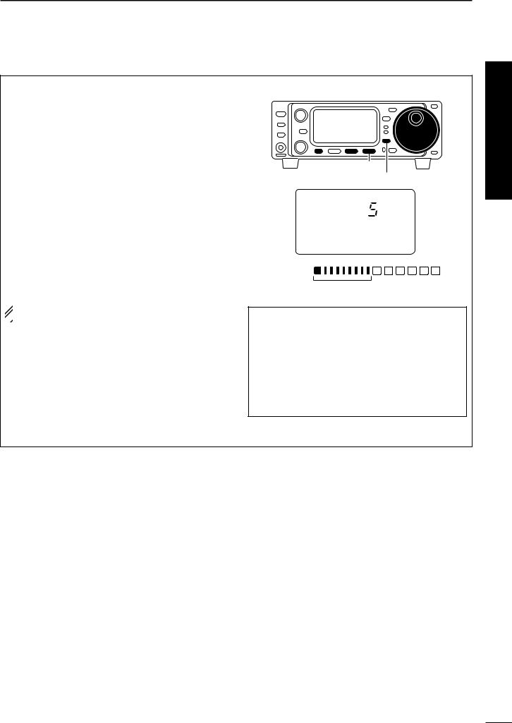
c.Automatic Notch: The automatic notch will track up to heterodynes. This is helpful for eliminating annoying transmitter “tune up” tones on any band, and to minimize continuous tone “heterodynes” encountered on the 40 meter phone bands at night, for example. Once selected an icon will appear “ANF” on the display.
qSelect S4.
•Push [DISPLAY] once or twice to select S.
• Push [MENU] one or more times to select S4.
wPush [(F-1)ANF] to activate the automatic notch filter.
 NOTE: Your IC-703 is equipped with an AGC cir-
cuit. This allows the DSP to filter out interfering sig-
 nals and QRM, while also taking this interference
out of the AGC. Bottom line, this will either elimi-
 nate or greatly reduce the pumping of the AGC
  from the interfering signal.
 [(F-1)]
[MENU] [DISPLAY]
USB
DSP
Appear ANF
|
|
|
BLANK |
S1 3 5 7 9 |
20 |
40 60dB |
VFO A |
PO |
5 |
10 |
CH |
S4 ANF NR NRL
Hint!
The Automatic Notch will not operate in the CW, RTTY or SSB-D modes.
d.Noise Blanker: The noise blanker function reduces pulse-type noise such as that generated by automobile ignition systems. This function is not effective for FM modes or for non pulse-type noise.
qSelect M3.
•Push [DISPLAY] once or twice to select M.
• Push [MENU] one or more times to select M3.
wPush [(F-2)NB] to activate the noise blanker.
•“NB” appears when the function is ON.
|
|
[MENU] |
[(F-2)] [DISPLAY] |
||
|
|
USB |
|
|
|
Appears |
|
NB |
|
|
BLANK |
|
|
|
|||
|
|
S1 3 5 7 9 |
20 |
40 60dB |
VFO A |
|
|
PO |
5 |
10 |
CH |
M3 FIL NB MET
e.Adjusting the Noise Blanker: The noise blanker is completely variable on how much of the Noise Blanker is used.
qPush [(F-2)NB] for 1 sec. to enter the noise blanker level set mode.
wRotate the main dial to set the noise blanker level.
ePush [DISPLAY] to exit the noise blanker level set mode.
[DISPLAY]
[(F-2)] |
Main dial |
USB
N1 NB LEVEL
Hint!
When using the noise blanker, received signals may be distorted if the noise blanker level setting has been too high.
VII
QUICK REFERENCE GUIDE
f.Filter:
One optional filter can be installed in the IC-703.
Narrow filters help reject interference from adjacent signals and obtain good selectivity.
Wide filters provide improved audio for SSB operation when no interfering signals are present.
Narrow filters for AM/FM modes are standard.
FILTER PRESETTING:
After you install a filter (see p. 87 for installation), you
must specify the installed filter in initial set mode (item “22 OPT. FIL” ; see p. 79).
FILTER ON/OFF: qSelect M3.
•Push [DISPLAY] once or twice to select M.
• Push [MENU] one or more times to select M3.
wPush [(F-1)FIL] momentarily to select the narrow filter; push for 1 sec. to select the wide filter.
•ã appears when the narrow filter is selected; ç appears when the wide filter is selected.
 NOTE: When selecting the narrow filter (or wide fil-
  ter), the graphic passband is changed (see dia-
  gram below).
wide is |
Normal |
narrow is |
selected |
operation |
selected |
 [(F-1)]
[MENU] [DISPLAY]
N W |
|
USB |
|
|
|
|
|
|
BLANK |
S1 |
3 |
5 7 9 20 |
40 60dB |
VFO A |
PO |
|
5 |
10 |
CH |
M3 FIL NB MET
Either these
appears when selected
Quick Reference
We hope these pointers have been helpful. Now you are ready for the “Ready to call CQ?”.
VIII
QUICK REFERENCE GUIDE
■ Ready to call CQ?
[POWER]: OFF
[P.AMP/ATT]: OFF (indicator lights out)
[TUNER]: OFF (indicator lights out)
[RIT/SUB]: OFF (indicator lights out)
[SHIFT]: Center
|
|
|
|
|
|
|
[AF]: Max. CCW |
|
AF |
RF SQL |
|
|
MODE |
Y |
CCW : counterclockwise |
POWER |
|
|
|
|
|
BAND |
|
|
|
|
|
TS |
|
|
|
|
|
|
|
|
|
[RF/SQL]: Center |
|
P.AMP ATT |
|
|
|
|
|
|
|
|
|
|
|
|
RX |
|
|
TUNER |
RIT |
|
|
|
TX |
|
|
SUB |
|
|
|
|
|
|
|
|
|
|
|
|
|
|
|
|
M-CH |
SHIFT |
|
|
DISPLAY |
|
|
PHONES |
|
|
|
|
|
|
|
|
|
|
|
|
LOCK |
BAND |
|
|
|
|
|
|
|
|
|
|
|
MENU F 1 |
F 2 |
F 3 |
|
Z |
|
[LOCK]: OFF (indicator light out)
1. Setting up your Mic Gain
Microphone gain must be adjusted properly so that your signal does not distort when transmitted.
qSelect SSB or another phone mode (AM or FM mode).
wPush [DISPLAY] for 1 sec. to select quick set mode.
ePush [MENU] one or more times to select “Q2 MIC GAIN.”
•The ALC meter is selected automatically when operating in SSB mode.
rWhile speaking into the microphone, rotate the main dial to adjust the microphone gain so that the
ALC meter does not peak past the ALC zone.
•While transmitting at your normal voice level, the ALC meter should read at about the middle of the ALC zone.
• Be sure the mic gain is in the range of 2 to 5. tPush [DISPLAY] to exit quick set mode.
|
|
|
|
|
|
|
[DISPLAY] |
[MENU] |
|
|
|
Main dial |
|||
|
|
|
USB |
|
|
|
|
S1 |
3 |
5 |
7 |
9 |
20 |
40 |
60dB |
ALC
Q2 MIC GAIN
ALC
ALC zone
IX
QUICK REFERENCE GUIDE
2. Speech compressor
The IC-703 has a built-in, low distortion speech compressor circuit. This circuit increases your average talk power in SSB mode and is especially useful for DX’ing when the receiving station is having difficulty copying your signal.
qSelect USB or LSB mode.
wSelect the ALC meter.
•Push [DISPLAY] once or twice to select M.
•Push [MENU] one or more times to select M3, then push
[(F-3)MET] one or more times to select “ALC.” eSelect M4.
•Push [MENU] one more time to select M4.
rPush [(F-2)COM] to turn the speech compressor function ON.
•“COM” appears.
tPush [(F-2)COM] for 1 sec. to enter the compression level set mode (p. 54).
yRotate the main dial to set the speech compression level.
 NOTE: When the ALC meter peaks at light the ALC
  zone, your transmitted voice may be distorted.

 [(F-3)]
  [MENU] [(F-2)] [DISPLAY] Main dial
USB
S1 |
3 |
5 |
7 |
9 |
20 |
40 |
60dB |
ALC
C1 COMP LEVEL
ALC
ALC zone
Hint!
Voice patterns and audio characteristics vary with each operator, therefore the Microphone gain, speech compression settings will be different for each operator. Actual on air experimenting is necessary to get just the right sound. It’s best to test and adjust your audio on the air, while someone who knows what your real voice sounds like listens, and provides and opinion on your audio quality.
Quick Reference
Verify you have selected a clear frequency and call out your CQ!
X
1 PANEL DESCRIPTION
■Front panel
q |
|
w e |
|
|
|
AF |
RF SQL |
|
POWER |
|
|
|
P.AMP ATT |
|
|
@2 |
|
|
|
@1 |
TUNER |
RIT |
|
|
SUB |
|
|
@0 |
|
|
|
|
M-CH |
SHIFT |
|
|
|
||
PHONES
!9
|
|
r |
t y u i |
o |
|
|
|
MODE |
Y |
|
|
|
|
|
USB |
|
|
|
BAND |
|
|
TS |
|
|
|
|
|
|
|
|
|
|
RX |
|
S1 3 5 7 9 |
20 |
40 60dB VFO A |
TX |
|
PO |
5 |
10 |
CH |
!0 |
|
M1 SPL A/B XFC DISPLAY
|
|
|
|
LOCK |
|
|
|
|
BAND |
MENU |
F 1 |
F 2 |
F 3 |
Z |
|
|
|
|
!8!7 !6 !5 |
!4 |
!3!2 |
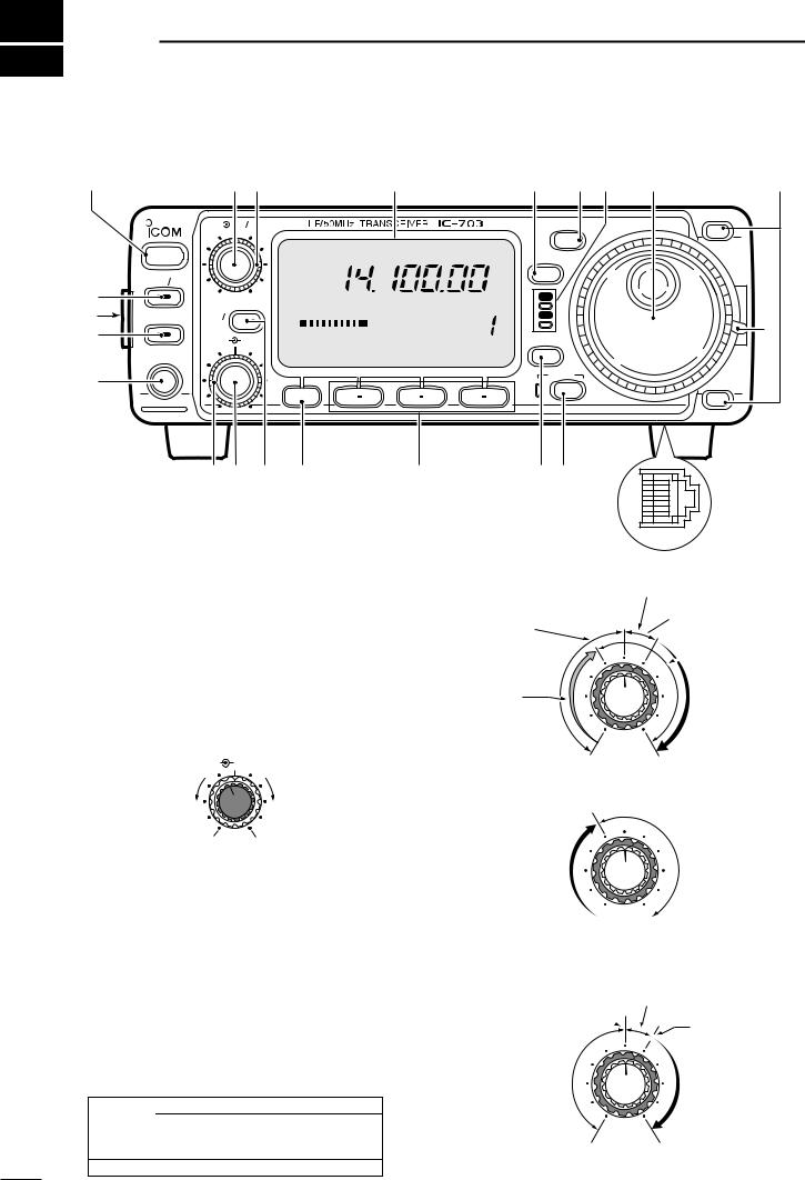
qPOWER SWITCH [POWER] (p. 17)
While transceiver’s power is OFF: Push to turn power ON.
• Turn the DC power supply ON in advance.
While transceiver’s power is ON:
Push momentarily to indicate the connected power supply voltage.
Push for 1 sec. to turn power OFF.
wAF GAIN CONTROL [AF] (inner control; p. 17) Varies the audio output level from the speaker.
AF |
RF/SQL |
Decreases |
Increases |
No audio output |
Max. audio output |
eRF GAIN CONTROL/SQUELCH CONTROL [RF/SQL] (outer control; p. 24)
Adjusts the RF gain and squelch threshold level. The squelch removes noise output from the speaker (closed condition) when no signal is received.
•The squelch is particularly effective for FM. It is also available for other modes.
•12 to 13 o’clock position is recommended for any setting of the [RF/SQL] control.
•The control can be set as ‘Auto’ (RF gain control in SSB, CW and RTTY; squelch control in AM and FM) or squelch control (RF gain is fixed at maximum) in initial set mode as follows. (p. 79)
MODE |
SET MODE SETTING |
|||
AUTO |
SQL |
RF GAIN + SQL |
||
|
||||
SSB, CW |
RF GAIN |
SQL |
RF GAIN + SQL |
|
RTTY |
||||
|
|
|
||
AM, FM |
SQL |
SQL |
RF GAIN + SQL |
|
!1
• When setting as RF gain/squelch control
Noise squelch (FM mode)
Recommended level
Squelch is
open.
 Maximum RF gain
RF gain |
|
adjustable |
S-meter |
range |
squelch |
•When functioning as RF gain control
(Squelch is fixed open; SSB, CW, RTTY only)
Maximum
RF gain
Adjustable range
Minimum RF gain 
•When functioning as squelch control
(RF gain is fixed at maximum.)
Noise squelch (FM mode)
Noise squelch
threshold  (FM mode)
S-meter squelch threshold
Squelch is |
S-meter |
|
squelch |
||
open. |
||
|
||
Shallow |
Deep |
1
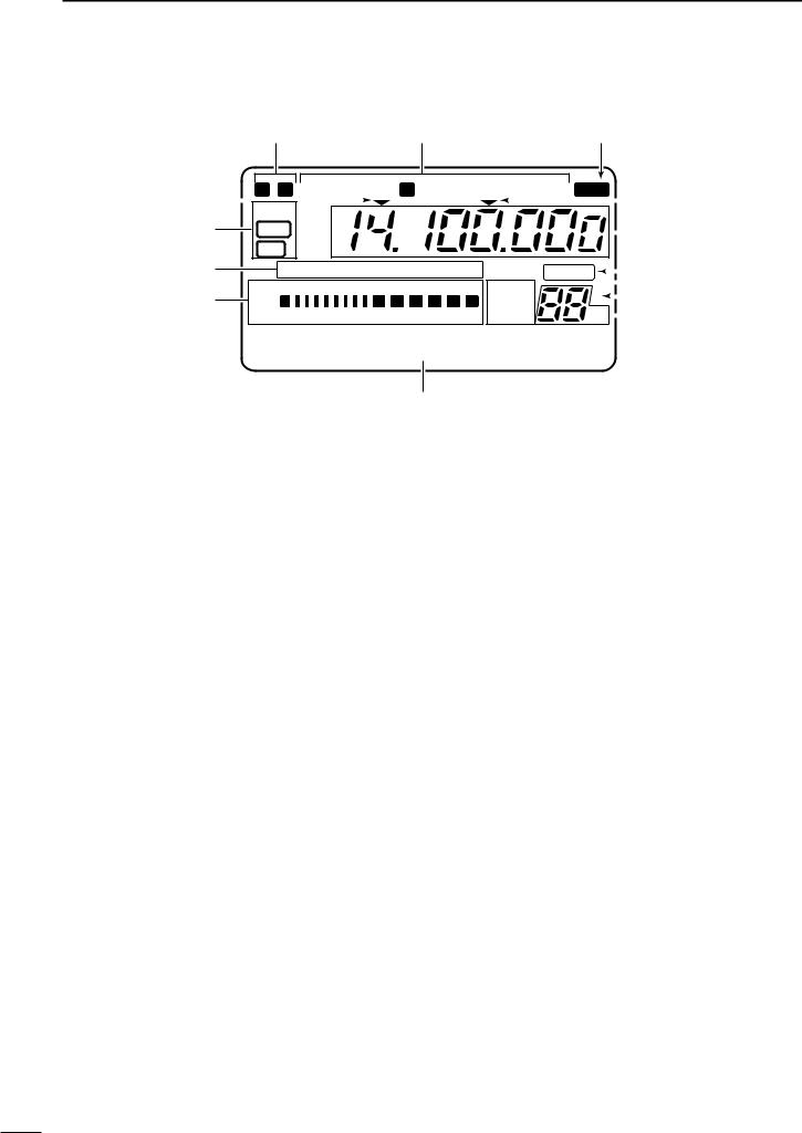
rFUNCTION DISPLAY
Shows the operating frequency, dot matrix indications, selected memory channel, etc. See p. 9 for details.
tTUNING STEP SWITCH [TS] (pgs. 19–21)
While in SSB/CW/RTTY modes, push momentarily to turn the programmable tuning step ON and OFF. While in FM/AM mode push momentarily to toggle the programmable tuning step and 1 MHz quick tuning step.
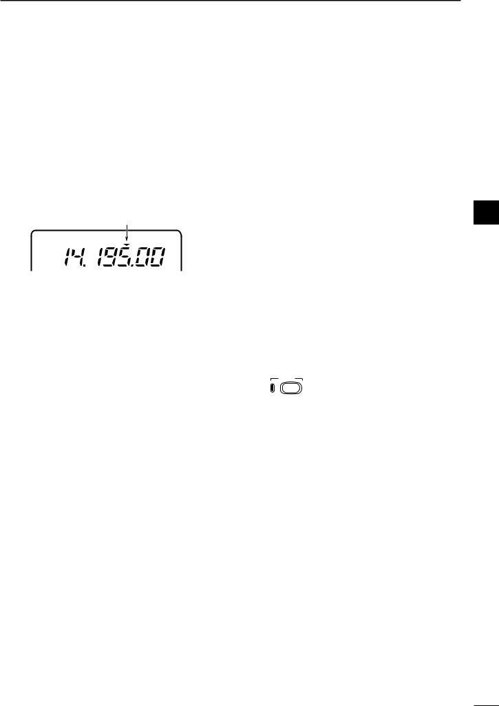
•While the programmable tuning step indicator is displayed, the frequency can be changed in programmed kHz steps.
Programmable tuning step indicator
USB
•0.01 (FM/AM mode only), 0.1, 1, 5, 9, 10, 12.5, 20, 25 and 100 kHz tuning steps are available.
•1 MHz quick tuning step are only available in FM and AM modes.
While the programmable tuning step is OFF, turns the 1 Hz step ON and OFF when pushed for 1 sec.
•1 and 10 Hz steps are only available in SSB, CW and RTTY modes.
•1 Hz indication appears, and the frequency can be changed in 1 Hz steps.
While the programmable tuning step is ON, enters the tuning step selection mode when pushed for 1 sec.
yMODE SWITCH [MODE] (p. 23)
Push momentarily to cycle through the operating modes:
USB/LSB CW RTTY/SSB-D FM/AM
Push for 1 sec. to toggle the following operating modes:
USB LSB
CW Memory keyer mode RTTY SSB-D (SSB data mode) FM AM
uRECEIVE/TRANSMIT INDICATORS [RX]/[TX]
[RX]: Lights green while receiving a signal and when squelch is open.
[TX]: Lights red while transmitting.
iMAIN DIAL
Changes the displayed frequency, sets the values of selected initial set mode items, etc.
PANEL DESCRIPTION |
1 |
oUP/DOWN (BAND) SWITCHES [Y/Z(BAND)]
Push momentarily to select a band.
•Can also be used to advance or back the quick set mode items, initial set mode items, etc.
Push and hold to scroll through the bands continuously.
!0MAIN DIAL TENSION LATCH
Selects the main dial tension.
• 2 positions are available.
!1MICROPHONE CONNECTOR (p. 10) Modular-type microphone connector—Accepts the supplied microphone (HM-103).
•The optional OPC-589 can be used to connect an 8-pin 1 microphone such as the SM-8 or SM-20, if desired.
•A microphone connector is also available on the rear panel. DO NOT connect 2 microphones simultaneously.
!2LOCK SWITCH [LOCK]
Push momentarily to toggle the dial lock function ON and OFF.
•The dial lock function electronically locks the main dial.
When the optional UT-102 VOICE SYNTHESIZER UNIT is installed (p. 86), push for 1 sec. to have the frequency, etc. announced.
•UT-102 operation can be adjusted in the initial set mode (p. 82).
LOCK
Lights while the lock function is activated.
!3DISPLAY SWITCH [DISPLAY] (p. 94)
Push momentarily to select one of the three menu sets: M1 to M4, S1 to S4 and G1 to G4.
Push for 1 sec. to enter the quick set mode.
!4MULTI-FUNCTION SWITCHES [F1] / [F2] / [F3]
Push to select the function indicated in the dot matrix display above these switches. (pgs. 4–6, 94)
• Functions vary depending on the menu set selected.
Push to edit a character for memory keyer programming or memory name. (pgs. 35, 59)
!5MENU SWITCH [MENU] (p. 94)
Push this switch one or more times to select menus within a menu set (M, S or G), or push to advance through the quick set mode and initial set mode displays.
Push for 1 sec. to jump between two different function menu sets.
2
1 PANEL DESCRIPTION
!6RIT/SUB DIAL SWITCH [RIT/SUB] (pgs. 21, 47)
Push to toggle the RIT or SUB DIAL function ON and OFF—initial set mode is used to select the desired action*.
•Lights green when the SUB DIAL function is ON; lights red when the RIT function is ON.
•Use the [M-CH] control to vary the RIT frequency or SUB DIAL frequency (see below).
When the RIT function is ON, push for 1 sec. to add or subtract the shifted frequency to the operating frequency.
RIT/
SUB
Lights red while the RIT function is activated; green while the SUB DIAL function is activated.
*Even if RIT is selected in initial set mode, RIT cannot be selected when operating AM or FM modes.
What is the RIT function?
The RIT (Receiver Incremental Tuning) shifts the receive frequency without shifting the transmit frequency.
This is useful for fine tuning stations calling you on an off-fre- quency or when you prefer to listen to slightly differentsounding voice characteristics, etc.
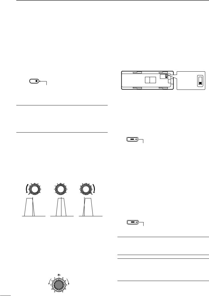
!7SHIFT CONTROL [SHIFT] (outer control; p. 47) Shifts the center frequency of the receiver’s IF passband.
•Rotate the control clockwise to shift the center frequency higher, or rotate the control counterclockwise to shift the center frequency lower.
•When rotate the control, the IF passband is graphically displayed and changes in accordance with the [SHIFT] control.
M-CH 
 SHIFT M-CH
 SHIFT M-CH
  SHIFT
SHIFT
Shifts low |
Center |
Shifts high |
!8M-CH CONTROL [M-CH] (inner control)
When the RIT or SUB DIAL functions are OFF, rotate to select a memory channel number (p. 56).
Shifts the receive frequency while the RIT function is ON in SSB, CW and RTTY modes (see above or p. 47).
• RIT variable range is ± 9.99 kHz
Changes the operating frequency in the selected tuning steps while the SUB DIAL function is ON (p. 21).
M-CH |
SHIFT |
Decreases |
Increases |
!9HEADPHONE JACK [PHONES] (p. 14) Accepts headphones with 8–16 Ω impedance.
•When headphones are connected, no receive audio comes from the speaker.
•When the PHONES/SPEAKER switch on the back of the front panel is set to the [SPEAKER] position, an external speaker can be connected. This is convenient for mobile or outdoor operation.
Back of the front panel
PHONES ∫ |
PHONES ∫ |
SPEAKER √ |
SPEAKER √
@0TUNER SWITCH [TUNER] (pgs. 64–66)
Push momentarily to toggle the automatic antenna tuner function ON and OFF (bypass).
•Lights red when the automatic antenna function is ON.
Push this switch for 1 sec. to manually tune the antenna.
•When the tuner cannot tune the antenna, the tuning circuit is bypassed automatically after 20 sec.
TUNER
Lights while the automatic tuning function is activated.
@1FRONT PANEL LATCH (p. 12)
Pull away from the transceiver (towards yourself when looking at the front of the transceiver) to detach the front panel from the main body of the transceiver.
@2PRE AMP/ATTENUATOR SWITCH [P.AMP/ATT]
(p. 46)
Push momentarily to turn the preamp ON or OFF.
Push for 1 sec. to turn the 20 dB attenuator ON;
push momentarily to turn the attenuator OFF.
•Lights green when the preamp is ON; lights red when the 20 dB attenuator is ON.
P.AMP/ATT
Lights green while the preamp is activated; lights red while the attenuator is activated.
What is the preamp?
The preamp amplifies received signals in the front end circuit to improve the S/N ratio and sensitivity. Turn ON ‘P.AMP’ when receiving weak signals.
What is the attenuator?
The attenuator prevents a desired signal from distorting when very strong signals are near the desired frequency, or when very strong electric fields, such as from a broadcasting station, are near your location.
3
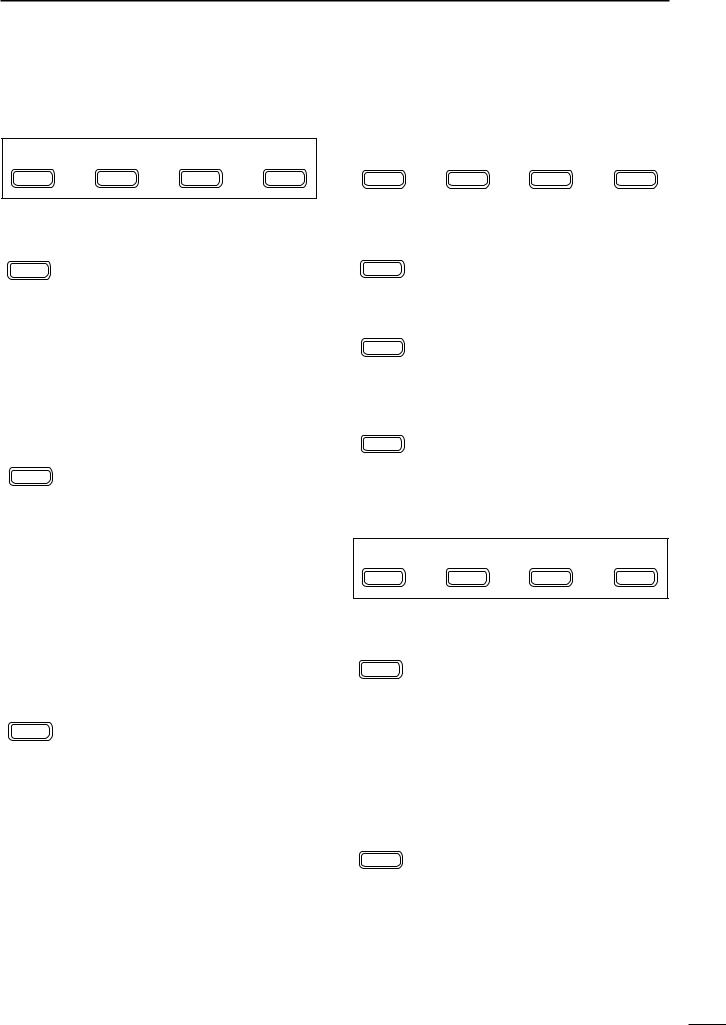
■Multi-function switches
DM1 functions
M1 |
SPL |
A/B |
XFC |
MENU |
F-1 |
F-2 |
F-3 |
SPLIT OPERATION (p. 30)
SPL Push momentarily to toggle the split function ON and OFF. (p. 51)
F-1 |
• “ä”appears when the split function is ON. |
Push for 1 sec. to turn the quick split function ON. (p. 52)
•The offset frequency must be programmed in advance using initial set mode. (p. 80)
•The offset frequency is shifted from the displayed frequency.
•The quick split function can be turned OFF using initial set mode. (p. 79)
VFO A/B SELECTION
A/B Push momentarily to toggle VFO A and VFO B in VFO mode. (p. 18)
F-2 Push momentarily to toggle the transmission VFO and reception VFO during split operation. (p. 51)
Push momentarily to toggle the transmit and receive frequencies (and modes) of memory channels when the split function is turned ON.
Push for 1 sec. to equalize the frequency and operatingmode of the two VFO’s.
•The rear (undisplayed) frequency and operating mode are equalized to the front (displayed) VFO frequency and operating mode.
TRANSMIT FREQUENCY CHECK (p. 51)
XFC |
Monitors the transmit frequency when |
|
F-3 |
pushed and held. |
|
•While pushing this switch, the transmit fre- |
||
|
||
|
quency can be changed with the main dial. |
PANEL DESCRIPTION |
1 |
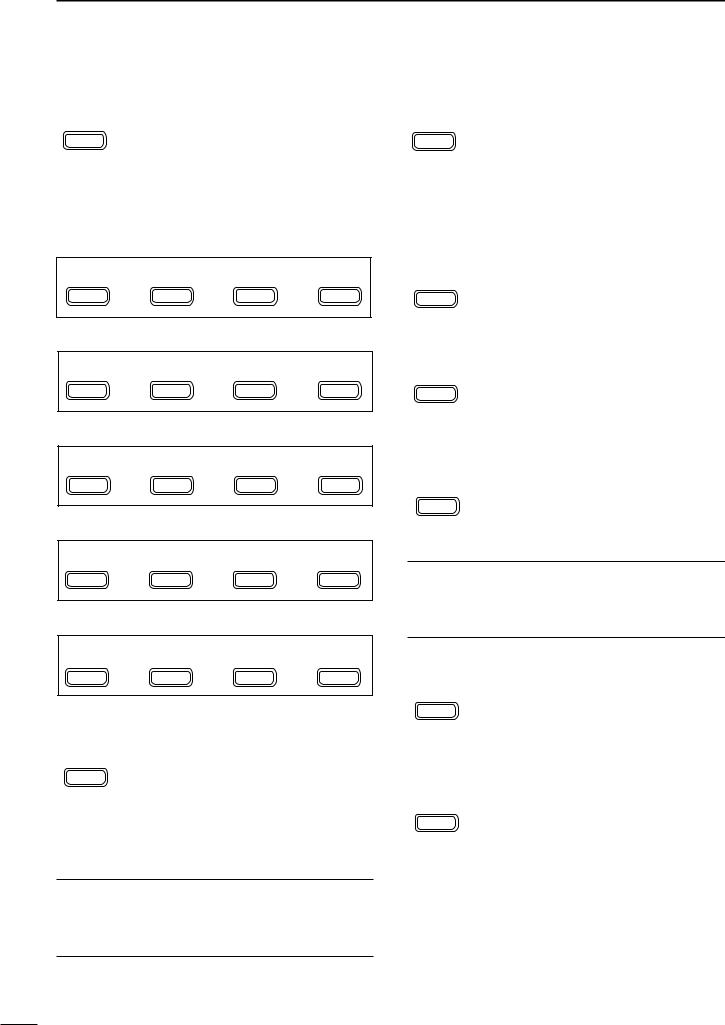
DM2 functions
M2 |
MW |
MCL |
V/M |
|
|
MENU |
F-1 |
F-2 |
F-3 |
|
|
|
|
|
|
|
|
MEMORY WRITE (p. 57) |
|
|
|
|
|
MW |
Push for 1 sec. to store the selected read- |
||||
F-1 |
out frequency and operating mode into |
||||
the displayed memory channel. |
|
|
|
||
|
|
|
|
||
MEMORY CLEAR (p. 58) |
|
|
1 |
||
|
|
|
|
||
MCL |
Push for 1 sec. to clear the selected read- |
|
|||
|
|||||
|
out memory channel contents. |
|
|
|
|
F-2 |
• “}” appears. |
|
•This switch does not function in VFO mode.
VFO/MEMORY
V/M Push momentarily to toggle between VFO and memory modes. (p. 56)
F-3 Push for 1 sec. to transfer the frequency and operating mode in the selected memory channel to a VFO. (p. 58)
DM3 functions
M3 FIL NB MET
MENU |
F-1 |
F-2 |
F-3 |
FILTER SELECTION (p. 49)
FIL |
Push to toggle the narrow filter (or wide |
|
F-1 |
filter—push for 1 sec.) ON and OFF. |
|
•“ã”appears when the narrow filter is ON; |
||
|
||
|
“ç” appears when the wide filter is ON. |
|
|
•An optional filter installation and presetting in |
|
|
initial set mode (p. 79) is necessary to use |
|
|
the following: |
|
|
CW/RTTY narrow: FL-52A or FL-53A |
|
|
SSB narrow: FL-222 |
|
|
SSB wide: FL-257 |
|
NOISE BLANKER (p. 48) |
||
NB |
Push momentarily to toggle the noise |
|
|
blanker ON and OFF. |
|
F-2 |
•“NB” appears when the noise blanker func- |
|
|
|
tion is ON. |
|
•The noise blanker does not function in FM |
|
mode; “30 AM NB” item (p. 80) in initial set |
|
mode must be set to ON for the noise |
|
blanker to work in AM mode. |
|
Push for 1 sec. to enter the noise blanker |
|
level set mode. |
|
•The noise blanker level can be set in noise |
|
blanker level set mode (p. 46). |
4
1 PANEL DESCRIPTION
METER SELECTION (p. 52)
MET |
Selects the type of meter displayed (dur- |
|
F-3 |
ing transmit) in the function display. |
|
•Power, ALC or SWR metering can be se- |
||
|
||
|
lected. |
|
|
•Only an S-meter is available for receive. |
DM4 functions
DURING SSB/AM OPERATION:
M4 VOX COM AGC
MENU |
F-1 |
F-2 |
F-3 |
DURING CW OPERATION:
M4 1/4 KEY AGC
MENU |
F-1 |
F-2 |
F-3 |
DURING RTTY OPERATION:
M4 1/4 TON AGC
MENU |
F-1 |
F-2 |
F-3 |
DURING SSB-D OPERATION:
M4 |
1/4 |
|
AGC |
MENU |
F-1 |
F-2 |
F-3 |
DURING FM OPERATION:
M4 VOX TON
MENU |
F-1 |
F-2 |
F-3 |
VOX FUNCTION (p. 53)
VOX Push momentarily to toggle the VOX function ON and OFF.
F-1 |
•“VOX” appears when the VOX function is |
ON.
Push for 1 sec. to enter the VOX set mode.
•The VOX delay, VOX gain and ANTI-VOX can be set in VOX set mode.
What is the VOX function?
The VOX function (voice operated transmission) starts transmission without pushing the PTT switch when you speak into the microphone; then, automatically returns to receive when you stop speaking.
SPEECH COMPRESSOR (p. 54)
COM Push momentarily to toggle the speech compressor ON and OFF.
F-2 |
•“COM” appears when the speech compres- |
sor is ON.
Push for 1 sec. to enter the compression level set mode.
AGC (p. 48)
AGC
F-3
•The COMP gain can be set in compression level set mode.
Push to change the time constant of the AGC circuit.
•“FAGC” appears when the fast time constant is selected.
1/4 FUNCTION
1/4 |
Push to toggle the 1/4 tuning function ON |
F-1 |
and OFF. |
•When the 1⁄4 function is ON, a bar appears |
|
|
under the 1⁄4 indication and fine tuning can be |
|
used. |
KEYER SET MODE (p. 32) |
|
KEY |
Push for 1 sec. to enter the keyer set |
|
mode. |
F-2 |
•The break-in setting, break-in delay time, CW |
|
|
|
pitch, CW paddle type and dot/dash ratio can |
|
be set in the keyer set mode. |
What is the break-in function?
Full break-in (QSK) activates the receiver between transmitted dots and dashes. This is useful when operating in nets, or during DX pileups and during contests, when “fast exchanges” are common.
RTTY TONE SET MODE (p. 40)
TON |
Push for 1 sec. to enter the RTTY tone set |
|
F-2 |
mode. |
|
•The RTTY tone frequency, RTTY shift fre- |
||
|
||
|
quency and RTTY keying polarity can be set |
|
|
in RTTY tone set mode. |
|
FM TONE OPERATION |
||
TON |
Push momentarily to select the subaudi- |
|
ble tone encoder for repeater use, tone |
||
F-2 |
squelch function and OFF. (pgs. 43–45) |
|
•“T” appears when the repeater tone function is ON. (pgs. 43, 45)
•“TSQL” appears when the tone squelch function is ON. (p. 43)
Push for 1 sec. to enter the FM tone set mode. (p. 44)
•The repeater tone frequency, tone squelch frequency can be set in FM tone set mode.
5
DS1 functions
S1 |
MW |
MPW |
MPR |
MENU |
F-1 |
F-2 |
F-3 |
|
|
|
|
MEMORY WRITE (p. 57) |
|
|
|
MW |
Push for 1 sec. to store the selected |
||
|
|||
F-1 |
readout frequency and operating mode |
||
into the displayed memory channel. |
|||
MEMO PAD WRITE (p. 60) |
|
|
|
MPW |
Push to store the the selected readout |
||
F-2 |
frequency and operating mode into a |
||
memo pad. |
|
|
|
|
|
|
|
MEMO PAD READ (p. 60) |
|
|
|
MPR |
Push to call up a memo pad. |
|
|
F-3 |
|
|
|
DS2 functions
DURING VFO MODE:
S2 SCN PRI V/M
MENU |
F-1 |
F-2 |
F-3 |
DURING MEMORY MODE:
S2 SCN SEL V/M
MENU |
F-1 |
F-2 |
F-3 |
SCAN (pgs. 61–63)
SCN |
Push to start or stop the scan function. |
F-1 |
|
PRIORITY WATCH (p. 63) |
|
PRI |
Push to start or stop the priority watch. |
F-2 |
|
VFO/MEMORY
V/M Push momentarily to toggle between VFO and memory modes. (p. 56)
F-3 Push for 1 sec. to transfer the frequency and operating mode in the selected memory channel to a VFO. (p. 58)
SELECT SCAN (p. 61)
SEL |
Push to toggle the select setting ON and |
F-2 |
OFF for the selected memory channel. |
|
PANEL DESCRIPTION |
1 |
DS3 functions
S3 7 14 21
MENU |
F-1 |
F-2 |
F-3 |
QUICK BAND CHANGE FUNCTION (p. 22)
This item provides access to the band stacking register. By default the 7, 14 and 21 MHz bands are displayed. Push [F-1], [F-2] or [F-3] for 1 sec. to select a new band if desired.
•A mode is memorized along with the frequency for each
band.
1
DS4 functions
(UT-106 is required for some version)
S4 ANF NR NRL
MENU |
F-1 |
F-2 |
F-3 |
AUTOMATIC NOTCH FILTER (p. 50)
ANF |
This function automatically attenuates |
|
F-1 |
beat tones, tuning signals, etc., even if |
|
they are moving. |
||
|
||
NOISE REDUCTION (p. 50) |
||
NR |
This function reduces noise components |
|
and picks out desired signals which are |
||
F-2 |
||
buried in the noise. |
||
NOISE REDUCTION LEVEL DISPLAY (p. 50) |
||
NRL |
This switch displays the noise reduction |
|
F-3 |
level when pushed. |
|
|
||
6

1 PANEL DESCRIPTION
■Rear panel
e |
r |
t y |
u |
i |
w |
|
|
|
|
q |
|
|
|
|
|
|
!0 |
|
o |
qANTENNA CONNECTOR [ANT] (p. 13)
Accepts a 50 Ω antenna with a PL-259 connector.
wGROUND TERMINAL [GND] (p. 11)
Connect this terminal to a ground to prevent electrical shocks, TVI, BCI and other problems.
eDATA SOCKET [DATA] (pgs. 8, 14)
6-pin min DIN socket to connect a TNC (Terminal Node Controller), etc. for packet operation.
•See page at right for socket information.
rACCESSORY SOCKET [ACC] (pgs. 8, 14) Enables connection to external equipment such as a TNC for data communications, a linear amplifier or an automatic antenna selector/tuner, etc.
•See page at right for socket information.
tEXTERNAL SPEAKER JACK [EXT SP] (p. 14) Accepts a 4–8 Ω speaker.
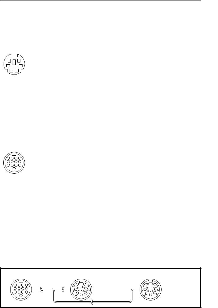
yCI-V REMOTE CONTROL JACK [REMOTE] (p. 71)
Designed for use with a personal computer for remote control of the transceiver functions.
Used for transceiver operation with another Icom CI-V transceiver or receiver.
uMICROPHONE CONNECTOR [MIC] (p. 13) Accepts the supplied microphone (connected in parallel with the front panel’s [MIC] connector).
•See p. 2 for microphone notes.
•See p. 10 for microphone connector information.
iELECTRONIC KEYER JACK [KEY] (p. 28) Accepts a paddle to activate the internal electronic keyer.
•Selection between the internal electronic keyer and straight key operation can be made in keyer set mode. (p. 32)
( )
When connecting a straight key
|
(dot) |
|
When connecting |
(com) |
|
(dash) |
||
a paddle |
||
|
 If you use an external electronic keyer, make sure
the voltage retained by the keyer is less than 0.4 V
 when the key is ON.
oTUNER CONTROL SOCKET [TUNER] (p. 14) Accepts the control cable from an optional AH-4
HF/50 MHz AUTOMATIC ANTENNA TUNER.
!0DC POWER SOCKET [DC13.8V] (p. 15)
Accepts 9.0–15.87 V DC through the supplied DC power cable.
 NOTE: DO NOT use a cigarette lighter socket as a
power source when operating in a vehicle. The plug
 may cause voltage drops and ignition noise may be
  superimposed onto transmit or receive audio.
7
PANEL DESCRIPTION |
1 |
DDATA socket
|
DATA |
|
PIN No. |
NAME |
|
DESCRIPTION |
|
|
|
|||
|
|
|
|
1 |
DATA IN |
Input terminal for data transmit. (1200 bps: AFSK/9600 bps: G3RUH, GMSK) |
|
|
||||
|
|
|
|
|
|
|
|
|
|
|||
|
|
|
|
2 |
GND |
|
Common ground for DATA IN, DATA OUT and AF OUT. |
|
|
|||
|
|
|
|
|
|
|
|
|
||||
6 |
5 |
3 |
PTT P |
PTT terminal for packet operation. Connect ground to transmit data. |
|
|
||||||
|
|
|
|
|
|
|
|
|
||||
4 |
DATA OUT |
Data out terminal for 9600 bps operation only. |
|
|
|
|||||||
4 |
|
|
3 |
|
|
|
||||||
|
|
|
|
|
|
|
|
|
|
|
||
|
2 |
1 |
|
5 |
AF OUT |
Data out terminal for 1200 bps operation only. |
|
|
|
|||
|
|
|
|
|
|
|
|
|
|
|
||
Rear panel view |
|
|
|
|
Squelch out terminal. Becomes ground level when the transceiver receives a signal |
|
|
|||||
|
|
|
|
which opens the squelch. |
|
|
|
|
||||
|
|
|
|
|
|
|
|
|
|
|
|
|
|
|
|
|
6 |
SQ |
|
•To avoid unnecessary TNC transmission, connect squelch to the TNC to inhibit trans- |
|
|
|||
|
|
|
|
|
|
1 |
||||||
|
|
|
|
|
|
|
|
mission when receiving signals. |
|
|
|
|
|
|
|
|
|
|
|
|
• Keep audio output at a normal level, otherwise a “SQ” signal will not be output. |
|
|
||
|
|
|
|
|
|
|
|
|
|
|||
|
|
|
|
|
|
|
|
|
|
|||
DACC socket |
|
|
|
|
|
|
|
|
||||
|
|
|
|
|
|
|
|
|
|
|
||
|
ACC |
|
PIN No. |
NAME |
|
|
DESCRIPTION |
SPECIFICATIONS |
|
|
||
|
|
|
|
1 |
8 V |
|
Regulated 8 V output. |
Output voltage |
: 8 V ±0.3 V |
|
|
|
|
|
|
|
|
Output current |
: Less than 10 mA |
|
|
||||
|
|
|
|
|
|
|
|
|
|
|
||
|
|
|
|
|
|
|
|
|
|
|
|
|
|
|
|
|
2 |
GND |
|
Connects to ground. |
——— |
|
|
|
|
|
|
|
|
|
|
|
|
|
|
|
|
|
|
|
|
|
|
|
|
Input/output pin. (HF/50 MHz only) |
Ground level |
: –0.5 V to 0.8 V |
|
|
|
|
|
|
|
3 |
HSEND |
Goes to ground when transmitting. |
Output current |
: Less than 20 mA |
|
|
||
|
|
|
|
|
|
|
When grounded, transmits. |
Input current (Tx) |
: Less than 200 mA |
|
|
|
|
|
|
|
|
|
|
|
|
|
|
|
|
|
|
|
|
4 |
BDT |
|
Data line for the optional AT-180. |
——— |
|
|
|
|
4 |
3 |
2 |
1 |
|
|
|
|
|
|
|
|
|
|
|
|
Band voltage output. |
|
|
|
|
|||||
8 |
7 |
6 |
5 |
5 |
BAND |
|
Output voltage |
: 0 to 8.0 V |
|
|
||
12 |
11 |
10 |
9 |
|
|
|
(Varies with amateur band) |
|
|
|
|
|
|
13 |
|
|
|
|
|
|
|
|
|
|
|
|
|
6 |
ALC |
|
ALC voltage input. |
Control voltage |
: –4 V to 0 V |
|
|
|||
|
|
|
|
|
|
|
||||||
Rear panel view |
|
Input impedance |
: More than 10 kΩ |
|
|
|||||||
|
|
|
|
|
|
|
||||||
q brown |
i gray |
7 |
NC |
|
——— |
——— |
|
|
|
|||
|
|
|
|
|
|
|
|
|
||||
w red |
|
o white |
8 |
13.8 V |
|
13.8 V output when power is ON. |
Output current |
: Max. 1 A |
|
|
||
e orange !0black |
|
|
|
|
|
|
|
|
|
|||
9 |
TKEY |
|
Key line for the optional AT-180. |
——— |
|
|
|
|||||
r yellow |
!1pink |
|
|
|
|
|||||||
t green |
!2light |
|
|
|
|
|
|
|
|
|
||
|
|
|
|
|
“High” level |
: More than 2.4 V |
|
|
||||
y blue |
|
blue |
|
|
|
|
|
|
|
|||
u purple |
!3light |
10 |
FSKK |
|
Controls RTTY keying |
“Low” level |
: Less than 0.6 V |
|
|
|||
|
|
|
green |
|
|
|
|
|
Output current |
: Less than 2 mA |
|
|
|
|
|
|
|
|
|
|
|
|
|
|
|
|
|
|
|
11 |
MOD |
|
Modulator input. |
Input impedance |
: 10 kΩ |
|
|
|
|
|
|
|
|
|
|
Connects to a modulator. |
Input level |
: Approx. 100 mV rms |
|
|
|
|
|
|
|
|
|
|
AF detector output. |
Output impedance |
: 4.7 kΩ |
|
|
|
|
|
|
|
12 |
AF |
|
Fixed, regardless of [AF] position in |
|
|
|||
|
|
|
|
|
|
|
default settings. |
Output level |
: 100–300 mV rms |
|
|
|
|
|
|
|
|
|
|
|
|
|
|
||
|
|
|
|
|
|
|
|
|
|
|
|
|
|
|
|
|
13 |
SQLS |
|
Squelch output. |
SQL open |
: Less than 0.3 V/5 mA |
|
|
|
|
|
|
|
|
|
|
Goes to ground when squelch opens. |
SQL closed |
: More than 6.0 V/100 µA |
|
|
|
Color refers to the cable strands of the supplied cable.
• When connecting the ACC conversion cable (OPC-599)
|
|
|
|
ACC 1 |
|
q FSKK |
t AF |
ACC 2 |
|
q 8 V |
t ALC |
|
4 |
3 |
2 |
1 |
7 |
6 |
7 |
6 |
|||||
|
|
|||||||||||
8 |
7 |
6 |
5 |
|
8 |
w GND |
y SQLS |
|
|
w GND |
y VSEND |
|
3 |
1 |
3 |
1 |
|||||||||
12 |
11 |
10 |
9 |
5 |
4 |
e HSEND |
u 13.8 V |
5 |
4 |
e HSEND |
u 13.8 V |
|
|
|
13 |
|
|
2 |
r MOD |
i ALC |
|
2 |
|||
|
|
|
|
|
|
|
||||||
|
|
|
|
|
|
|
r BAND |
|
||||
|
|
|
|
|
|
|
|
|
|
|
Connect to ACC socket
8
1 PANEL DESCRIPTION
■Function display
q w e
rb |
|
|
|
N W |
LSB USB CW |
R RTTY AM |
FM |
|
|
TSQL SPL |
|
|
ra |
|||||||||||
|
|
|
||||||||||||||||||||||
|
|
|
DSP |
|
|
|
|
|
|
|
|
|
|
|
|
|
|
|
||||||
!3 |
|
|
|
|
|
|
|
|
|
|
|
|
|
|
|
|
|
|
|
|
|
|
||
|
|
|
ANF |
|
|
|
|
|
|
|
|
|
|
|
|
|
|
|
t |
|||||
|
|
|
|
|
|
|
|
|
|
|
|
|
|
|
|
|
||||||||
|
|
|
|
NR |
|
|
|
|
|
|
|
|
|
|
|
|
|
|
|
|
|
|
|
|
!2 |
|
|
|
|
NB VOX F-BK COM FAGC |
|
|
|
|
|
|
|
|
|
|
|
|
|
||||||
|
|
|
|
VFO A |
|
BLANK |
u y |
|||||||||||||||||
|
|
|
|
|
|
|||||||||||||||||||
|
|
|
|
|
S1 |
3 |
5 |
7 9 |
20 40 |
60dB |
|
|
|
|
|
|
|
|
i |
|||||
!1 |
|
ALC |
|
|
|
|
∞ |
|
VFO B |
|
S |
|
|
|
|
|||||||||
|
|
|
|
|
|
|
|
|
|
|
|
|||||||||||||
|
|
SWR PO 1 |
1.5 |
2 |
3 5 |
10 |
MEMO |
|
CH |
|
|
|
o |
|||||||||||
|
|
|
|
|
|
|||||||||||||||||||
|
|
|
|
|
|
|
|
|||||||||||||||||
|
|
|
|
M1 SPL A/B XFC |
|
|
|
|
|
|||||||||||||||
|
|
|
|
|
|
|
|
|
||||||||||||||||
!0
qNARROW/WIDE FILTER INDICATORS
“ã” appears when selecting AM narrow or FM narrow modes.
When installing an optional narrow filter, narrow mode can be selected in CW, RTTY and SSB modes.
•When the SSB wide filter is installed, “ç” appears during wide mode selection.
wMODE INDICATORS
Show the selected operating mode.
•“å” appears when CW reverse or RTTY reverse mode is selected.
eSPLIT INDICATOR
Appears during split operation.
rPROGRAMMABLE/1 MHz TUNING STEP INDICATORS
ra appears when the programmable tuning step is selected.
rb appears when the 1 MHz quick tuning step is selected.
tFREQUENCY READOUT
Shows the operating frequency.
yBLANK MEMORY INDICATOR
Appears when the displayed memory channel is not programmed (blank channel).
• This indicator appears both in VFO and memory modes.
uVFO/MEMORY INDICATORS
VFO A or B appears when VFO mode is selected; MEMO appears when memory mode is selected.
iSELECT MEMORY CHANNEL INDICATOR
Appears when the selected memory channel is set as a select memory channel.
oMEMORY CHANNEL READOUT
Shows the selected memory channel.
!0DOT MATRIX INDICATORS
These alphanumeric readouts show a variety of information such as current functions of the “F” keys [F1] to [F3], memory channel names, set mode items, etc. See p. 94 for an overview of these indicators.
!1METER READOUTS
Shows receiving signal strength while receiving.
Shows one of transmit power meter, ALC or SWR meter while transmitting.
!2FUNCTION INDICATORS
“NB” appears when the noise blanker is activated.
“VOX” appears when the VOX function is selected.
“F-BK” appears when full break-in operation is selected and only “BK” appears when semi breakin operation is selected.
“COM” appears when the speech compressor is activated.
“FAGC” appears when the fast AGC function is selected.
!3DSP INDICATORS
Appear when the (optional*) DSP unit UT-106 is (installed and) activated.
* UT-106 DSP unit is optional for some version.
9
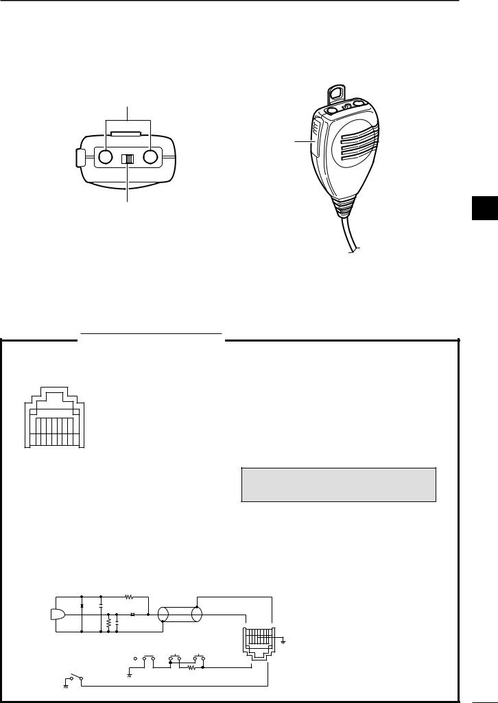
■Microphone (HM-103)
q
LOCK
DN UP
OFF ON
w
qUP/DOWN SWITCHES [UP]/[DN]
Change the operating frequency.
•Push and hold to change the frequency continuously. •Tuning step is 50 Hz when no TS indicator appears.
PANEL DESCRIPTION |
1 |
e
1
wLOCK SWITCH [LOCK]
Locks the [UP]/[DN] switches.
ePTT SWITCH [PTT]
Push and hold to transmit; release to receive.
TECHNICAL INFORMATION
• MICROPHONE CONNECTOR
Rear panel view
87654321
q +8 V DC output
w Frequency up/down e AF output
r PTT
t GND (Microphone ground) y Microphone input
u GND
iSquelch switch
•HM-103 SCHEMATIC DIAGRAM
PIN NO. |
FUNCTION |
DESCRIPTION |
|
1 |
+8 V DC output |
Max. 10 mA |
|
|
|
|
|
2 |
Frequency up |
Ground |
|
|
|
||
Frequency down |
Ground through 470 Ω |
||
|
|||
|
|
|
|
8 |
Squelch open |
“LOW” level |
|
|
|
||
Squelch closed |
“HIGH” level |
||
|
|||
|
|
|
CAUTION: DO NOT short pin 1 to ground as this can damage the internal 8 V regulator.
MICROPHONE 2k |
MICROPHONE PLUG |
||
|
|
|
MICROPHONE |
10 |
+ |
4700p |
CABLE |
|
|
||
MIC |
|
0.33 + |
|
ELEMENT |
|
|
|
|
|
4700p |
1 2345678 |
|
|
|
|
|
|
2.2k |
|
|
|
LOCK |
DOWN UP |
PTT |
RECEIVE |
470 |
|
|
|||
TRANSMIT
10
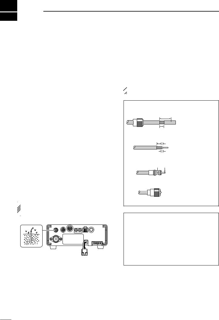
2 INSTALLATION AND CONNECTIONS
■ Unpacking |
■ Antenna connection |
After unpacking, immediately report any damage to the delivering carrier or dealer. Keep the shipping cartons.
For a description and a diagram of accessory equipment included with the IC-703, see ‘Supplied accessories’ on p. ii of this manual.
■ Selecting a location
Select a location for the transceiver that allows adequate air circulation, free from extreme heat, cold, or vibrations, and away from TV sets, TV antenna elements, radios and other electromagnetic sources.
The base of the transceiver has an adjustable stand for desktop use. Set the stand to one of two angles depending on your operating conditions. (see description at right page)
■ Grounding
To prevent electrical shock, television interference (TVI), broadcast interference (BCI) and other problems, ground the transceiver through the GROUND terminal on the rear panel.
For best results, connect a heavy gauge wire or strap to a long earth-sunk copper rod. Make the distance between the [GND] terminal and ground as short as possible.
 RWARNING: NEVER connect the [GND] ter-
minal to a gas or electric pipe, since the connection  could cause an explosion or electric shock.
For radio communications, the antenna is of critical importance, along with output power and sensitivity. Select antenna(s), such as a well-matched 50 Ω antenna, and feedline. 1.5:1 or better of Voltage Standing Wave Ratio (VSWR) is recommended for your desired band. Of course, the transmission line should be a coaxial cable.
 CAUTION: Protect your transceiver from lightning
  by using a lightning arrestor.
PL-259 CONNECTOR INSTALLATION EXAMPLE
q
Coupling ring
w
e
r
30 mm
10 mm (soft solder)
10 mm Soft solder
1–2 mm
solder solder
Slide the coupling ring down. Strip the cable jacket and soft solder.
Strip the cable as shown at left. Soft solder the center conductor.
Slide the connector body on and solder it.
Screw the coupling ring onto the connector body.
ANTENNA SWR
Each antenna is tuned for a specified frequency range and SWR may be increased out-of-range. When the SWR is higher than approx. 2.0 : 1, the transceiver’s power drops to protect the final transistors. In this case, an antenna tuner is useful to match the transceiver and antenna. Low SWR allows full power for transmitting even when using the antenna tuner. The IC-703 has an SWR meter to monitor the antenna SWR continuously.
11
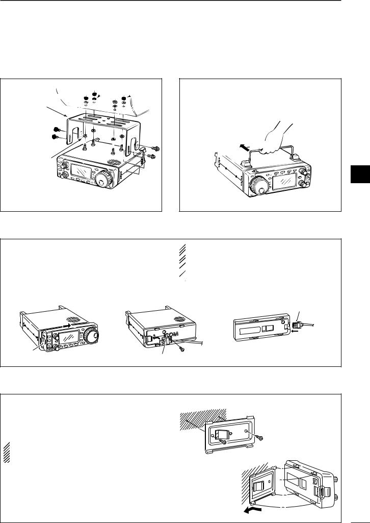
■Installation
DSingle body mounting
Spring washer


 Nut MB-62


(optional)
Supplied with 

 the MB-62*


Flat washer
*CAUTION: Non-supplied screws (longer than 8 mm) may damage the internal units.
INSTALLATION AND CONNECTIONS |
2 |
DStand
To raise the stand:
With the transceiver upside down, pull the stand towards the rear panel and then upwards, as illustrated below.
then up
Pull back
2
DFront panel separation
qWhile pulling the panel release button towards you, slide the front panel to the right (fig. 1).
wAttach the optional OPC-581 to the main body and tighten the supplied screw as in fig. 2.
eAttach the other end of the OPC-581 to the detached front panel as in fig. 3.
fig. 1 |
fig. 2 |
 CAUTION: NEVER detach/attach the front panel
 when connecting the DC power supply (or battery).
 Make sure the disconnecting DC power cable from
  the [13.8 V] receptacle on the transceiver rear
  panel.
fig. 3
Separation cable
Latch |
Separation cable |
|
DFront panel mounting
qAttach the MB-63 to a flat surface using the two |
fig. 1 |
|
supplied screws (fig. 1). |
||
|
wFix the detached front panel to the MB-63 as illustrated in fig. 2.
 BE CAREFUL of the orientation of the MB-63, otherwise, the front panel may become attached in the
opposite direction. |
fig. 2 |
|
12
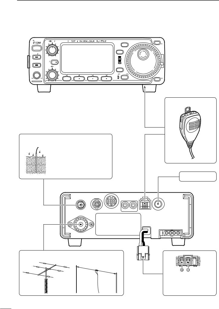
2 INSTALLATION AND CONNECTIONS
■Required connections
|
AF |
RF SQL |
|
|
MODE |
POWER |
|
|
|
|
TS |
|
|
|
|
|
|
P.AMP ATT |
|
|
|
|
|
|
|
|
|
|
RX |
TUNER |
RIT |
|
|
|
TX |
SUB |
|
|
|
|
|
|
|
|
|
|
|
|
M-CH |
SHIFT |
|
|
DISPLAY |
PHONES |
|
|
|
|
|
|
|
|
|
|
LOCK |
|
|
MENU |
F 1 |
F 2 |
F 3 |
GROUND (p. 11)
Use the heaviest gauge wire or strap available and make the connection as short as possible.
Grounding prevents electrical shocks, TVI and other problems.
HF/50 MHz ANTENNA
Y
BAND
BAND
Z
MICROPHONE (p. 10)
HM-103
CW KEY (p. 28)
Connects to DC 9.0–15.8 V power supply. See p. 15 for details.
13

INSTALLATION AND CONNECTIONS |
2 |
■Advanced connections
AF RF SQL |
MODE |
Y |
|
|
BAND
POWER |
|
TS |
|
|
|
P.AMP ATT |
|
|
|
|
RX |
TUNER |
RIT |
TX |
SUB |
|
|
|
|
|
|
M-CH SHIFT |
DISPLAY |
PHONES
LOCK
BAND
MENU |
F 1 |
F 2 |
F 3 |
Z |
HEADPHONES |
SPEAKER |
or
Selectable with the [PHONE/SPEAKER] switch on the back of the front panel.
ACC SOCKET (p. 8)
DATA SOCKET (p. 8)
6-pin mini DIN socket to connect to a TNC, etc. for packet operation.
OPC-589 (p. 92) |
2 |
EXTERNAL
SPEAKER (p. 91)
SM-20
SP-7/SP-10
DESKTOP (p. 91)
MICROPHONE
|
AH-4 |
(p. 16) |
REMOTE (p. 71) |
AH-2b |
Used for computer control |
||
|
|
|
and transceive operation. |
14
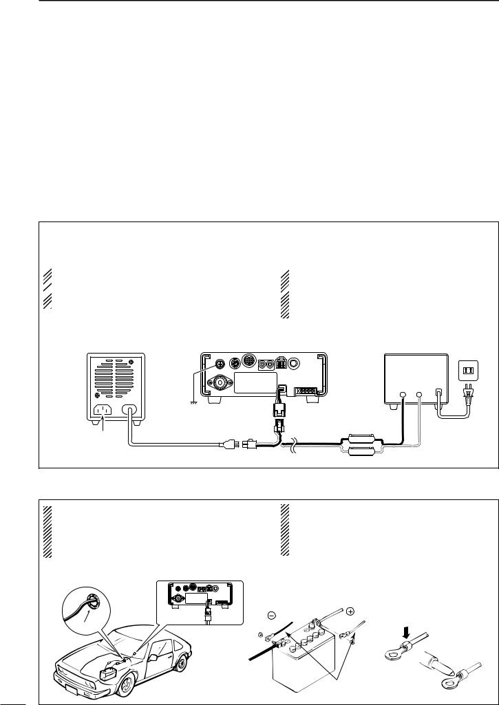
2 INSTALLATION AND CONNECTIONS
■DC Power voltage
Depending on the applied voltage from the connected |
when the voltage reaches 11.5 V. This 0.5 V voltage |
power supply, a boarder voltage of 11.0 V is set as the |
difference prevents irregular switching between nor- |
point where the IC-703 switches between normal op- |
mal mode and battery mode, caused by the voltage |
erating mode (over 11.0 V), and battery operating |
drop which are current capacity, receiving or transmit- |
mode (under 11.0 V: power save mode). |
ting. |
However when the connected voltage decreases from |
When 11.3 V voltage is applied, the IC-703 may acti- |
13.8 V to 11.0V, the IC-703 switches from normal |
vate the battery operating mode depending on the |
mode to battery mode. Conversely the IC-703 |
current capacity of the power supply. |
switches back to normal mode from battery mode |
|
|
|
■DC Power supply connections |
|
Use a 13.8 V DC power supply with at least 3 A capacity. when operating IC-703 with AC power. Refer to the diagram below for connection.
 CAUTION:
 Before connecting the DC power cable, check the
  following important items. Make sure:
 • The [POWER] switch is OFF.
 •Output voltage of the power source is 9.0–15.8 V
when you use a non-Icom power supply.
 •DC power cable polarity is correct.
Red: positive (+) terminal, Black: negative (–) terminal
CONNECTING PS-125 DC POWER SUPPLY |
CONNECTING A DC POWER SUPPLY |
PS-125 |
Transceiver |
|
Ground |
Optional |
to DC power |
|
receptacle |
|
|
OPC-1248 |
|
Connect to an AC |
DC power cable |
|
|
outlet using the |
|
supplied AC cable. |
|
*13.8 V; at least 3.0 A continuous AC
outlet
A DC power supply*
Black Red
_+
Supplied |
AC cable |
OPC-1229 |
|
4 A fuses |
|
■Battery connections
• RWARNING NEVER connect to a battery |
• DO NOT use the cigarette lighter socket for power |
|
without supplied DC fuse, otherwise a fire hazard |
|
connections. (See p. 7 for details) |
occur. |
• Attach a rubber grommet when passing the DC |
|
• NEVER connect the transceiver directly to a |
|
power cable through a metal plate to prevent a |
24 V battery. |
|
short circuit. |
CONNECTING A VEHICLE BATTERY |
|
|
|
|
Note: Use terminals for |
|
|
the cable connections. |
|
black |
red |
|
Crimp |
|
Grommet |
|
|
|
|
|
|
|
Solder |
|
12 V |
|
|
battery |
|
|
|
Supplied |
|
|
DC power cable |
15
 Loading...