

Page 1

THE TRANSCEIVER
i7800
Instruction Manual
A-6328H-1EX-r
Printed in Japan
© 2004 Icom Inc.
Page 2

i
FOREWORD
Congratulations! You are the owner of the world’s most advanced amateur
HF/50 MHz transceiver— IC-7800. The IC-7800 is designed and built with
Icom’s superior technology and craftsmanship. With proper care, this product should provide you with years of trouble-free operation.
We would like to take a few moments of your time to thank you for making
the IC-7800 your radio of choice, and hope you agree with Icom’s philosophy of “technology first.” Many hours of research and development went
into the design of your IC-7800.
D
FEATURES
❍ Ultimate receiver performance: third-order intercept (IP3)
of +40 dBm (HF bands only), both main and sub
❍ Independent identical receiver circuits for main and sub
bands provide perfect no-compromise Dualwatch operation
❍ Built-in Baudot RTTY and PSK31 modulator/demodulator
and direct PC keyboard connection capability for RTTY
and PSK31 operation without a PC
❍ Upgraded real-time spectrum scope— center frequency
and fix frequency modes, plus mini-scope displays
IMPORTANT
READ THIS INSTRUCTION MANUAL CAREFULLY before at-
tempting to operate the transceiver.
SAVE THIS INSTRUCTION MANUAL. This manual contains im-
portant safety and operating instructions for the IC-7800.
EXPLICIT DEFINITIONS
TRADEMARKS
Icom, Icom Inc. and the logo are registered trademarks of Icom
Incorporated (Japan) in the United States, the United Kingdom, Germany,
France, Spain, Russia and/or other countries.
WORD DEFINITION
RR
WARNING
Personal injury, fire hazard or electric shock may
occur.
CAUTION Equipment damage may occur.
NOTE
If disregarded, inconvenience only. No risk of personal injury, fire or electric shock.
Page 3

ii
PRECAUTIONS
R WARNING HIGH RF VOLTAGE! NEVER
attach an antenna or internal antenna connector during
transmission. This may result in an electrical shock or
burn.
R WARNING! NEVER operate the transceiver
with a headset or other audio accessories at high volume levels. Hearing experts advise against continuous
high volume operation. If you experience a ringing in
your ears, reduce the volume or discontinue use.
R CAUTION! NEVER change the internal set-
tings of the transceiver. This may reduce transceiver
performance and/or damage to the transceiver.
In particular, incorrect settings for transmitter circuits,
such as output power, idling current, etc., might damage the expensive final devices.
The transceiver warranty does not cover any problems
caused by unauthorized internal adjustment.
R CAUTION! NEVER touch the transceiver top
cover when transmitting continuously for long periods.
The top cover may be hot.
R CAUTION! The transceiver weighs approx. 25 kg
(55 lb). Always have two people available to carry, lift
or turn over the transceiver.
R CAUTION! The line-voltage receptacle must be
near the transceiver and must be easily accessible.
Avoid extension cords.
R ACHTUNG! Die Steckdose muß nabe bei
diesem Gerät angebracht und zugänglich sein.
R NEVER let metal, wire or other objects protrude
into the transceiver or into connectors on the rear
panel. This may result in an electric shock.
R NEVER block any cooling vents on the top, rear
or bottom of the transceiver.
R NEVER expose the transceiver to rain, snow or
any liquids.
R NEVER install the transceiver in a place without
adequate ventilation. Heat dissipation may be reduced,
and the transceiver may be damaged.
R NEVER operate or touch the transceiver with wet
hands. This may result in an electric shock or damage
to the transceiver.
DO NOT
use chemical agents such as benzine or alcohol when cleaning the IC-7800, as they can damage
the transceiver’s surfaces.
DO NOT push the PTT switch when you don’t actu-
ally desire to transmit.
AVOID using or storing the transceiver in areas with
temperatures below ±0°C (+32°F) or above +50°C
(+122°F).
AVOID placing the transceiver in excessively dusty environments or in direct sunlight.
AVOID placing the transceiver against walls or putting
anything on top of the transceiver. This may overheat
the transceiver.
Always place unit in a secure place to avoid inadvertent use by children.
BE CAREFUL! If you use a linear amplifier, set the
transceiver’s RF output power to less than the linear
amplifier’s maximum input level, otherwise, the linear
amplifier will be damaged.
Use Icom microphones only (supplied or optional).
Other manufacturers’ microphones have different pin
assignments, and connection to the IC-7800 may damage the transceiver or microphone.
The LCD display may have cosmetic imperfections that
appear as small dark or light spots. This is not a malfunction or defect, but a normal characteristic of LCD
displays.
During maritime mobile operation, keep the transceiver
and microphone as far away as possible from the magnetic navigation compass to prevent erroneous indications.
Turn [I/O] switch (on the rear panel) OFF and/or disconnect the AC power cable from the AC outlet when
you will not use the transceiver for long period of time.
For U.S.A. only
CAUTION: Changes or modifications to this device,
not expressly approved by Icom Inc., could void your
authority to operate this device under FCC regulations.
Page 4
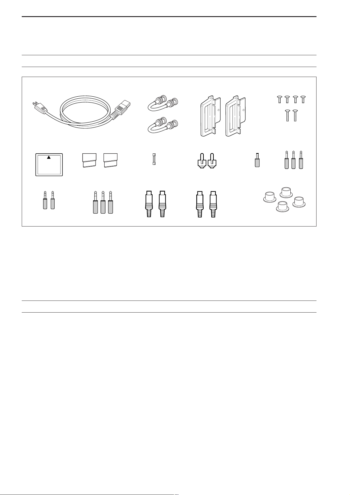
q AC power cable* ………………………………… 1
w Antenna jumper cables …………………………… 2
e Rack mounting handles ……………………… 1 pair
r Screws for rack mounting handles ………… 1 set
t CF (Compact Flash) memory card ……………… 1
y Stands ………………………………………… 1 pair
u Spare fuse (FGB 2 A) …………………………… 1
i RCA plugs ………………………………………… 2
o DC power plug …………………………………… 1
!0 2-conductor 1⁄8″ plugs …………………………… 3
!1 3-conductor 1⁄8″ plugs …………………………… 2
!2 3-conductor 1⁄4″ plugs …………………………… 3
!3 ACC plugs (7-pin) ………………………………… 2
!4 ACC plugs (8-pin) ………………………………… 2
!5 Antenna connector caps ………………………… 4
*May differ from that shown according to version
iii
SUPPLIED ACCESSORIES
Section 1 PANEL DESCRIPTION
■ Front panel ……………………………………………………………… 1-2
■ Rear panel ……………………………………………………………… 1-12
■ LCD display …………………………………………………………… 1-14
■ Screen menu arrangement …………………………………………… 1-15
Section 2 INSTALLATION AND CONNECTIONS
■ Unpacking ……………………………………………………………… 2-2
■ Antenna jumper cable connection …………………………………… 2-2
■ Selecting a location …………………………………………………… 2-2
■ Rack mounting handle attachment …………………………………… 2-2
■ Grounding ……………………………………………………………… 2-3
■ Antenna connection …………………………………………………… 2-3
■ CF (Compact Flash) memory card …………………………………… 2-3
■ Required connections ………………………………………………… 2-4
D Front panel …………………………………………………………… 2-4
D Rear panel …………………………………………………………… 2-4
■ Advanced connections ………………………………………………… 2-5
D Front panel …………………………………………………………… 2-5
D Rear panel—1 ……………………………………………………… 2-5
TABLE OF CONTENTS
q
!0
!1 !2 !3 !4 !5
yuio
e
w
r
t
Page 5

iv
D Rear panel—2 ……………………………………………………… 2-6
■ Linear amplifier connections …………………………………………… 2-7
D Connecting the IC-PW1/EURO …………………………………… 2-7
D Connecting a non-Icom linear amplifier …………………………… 2-7
■ Transverter jack information …………………………………………… 2-8
■ FSK and AFSK (SSTV) connections ………………………………… 2-8
■ Microphone connector information …………………………………… 2-9
■ Microphones (options) ………………………………………………… 2-9
D SM-20 ………………………………………………………………… 2-9
D HM-36 ………………………………………………………………… 2-9
■ Accessory connector information …………………………………… 2-10
Section 3 BASIC OPERATIONS
■ When first applying power (CPU resetting) ………………………… 3-2
■ Initial settings …………………………………………………………… 3-2
■ Main/Sub band selection ……………………………………………… 3-3
■ Selecting VFO/memory mode ………………………………………… 3-3
■ Selecting an operating band …………………………………………… 3-4
D Using the band stacking registers ………………………………… 3-4
■ Frequency setting ……………………………………………………… 3-5
D Tuning with the main dial …………………………………………… 3-5
D Direct frequency entry with the keypad …………………………… 3-5
D Quick tuning step …………………………………………………… 3-6
D Selecting “kHz” step ………………………………………………… 3-6
D1⁄4 tuning step function ……………………………………………… 3-6
D Selecting 1 Hz step ………………………………………………… 3-7
D Auto tuning step function …………………………………………… 3-7
D Band edge warning beep …………………………………………… 3-7
■ Operating mode selection ……………………………………………… 3-8
■ Volume setting ………………………………………………………… 3-9
■ RF gain adjustment …………………………………………………… 3-9
■ Squelch level adjustment ……………………………………………… 3-9
■ Meter indication selection …………………………………………… 3-10
D Multi-function digital meter ………………………………………… 3-10
D Meter type selection ……………………………………………… 3-11
■ Basic transmit operation ……………………………………………… 3-12
D Transmitting ………………………………………………………… 3-12
D Microphone gain adjustment ……………………………………… 3-12
D Drive gain adjustment ……………………………………………… 3-13
Section 4 RECEIVE AND TRANSMIT
■ Operating SSB ………………………………………………………… 4-2
D Convenient functions for receive ……………………………………4-2
D Convenient functions for transmit ……………………………………4-3
D About 5 MHz band operation (USA version only) …………………4-3
■ Operating CW …………………………………………………………… 4-4
D Convenient functions for receive ……………………………………4-4
D Convenient functions for transmit ……………………………………4-5
D About CW reverse mode ……………………………………………4-5
D About CW pitch control ………………………………………………4-5
D CW side tone function ………………………………………………4-5
D APF (Audio Peak Filter) operation …………………………………4-6
D About 137 kHz band operation (Europe, UK, Italy, Spain, France
versions only) …………………………………………………………4-6
■ Electronic keyer functions ……………………………………………… 4-7
TABLE OF CONTENTS
Page 6

D Memory keyer screen …………………………………………………4-8
D Editing a memory keyer ………………………………………………4-9
D Contest number set mode …………………………………………4-10
D Keyer set mode ………………………………………………………4-11
■ Operating RTTY (FSK) ……………………………………………… 4-13
D Convenient functions for receive …………………………………4-14
D About RTTY reverse mode …………………………………………4-14
D Twin peak filter ………………………………………………………4-14
D Functions for the RTTY decoder indication ………………………4-15
D Setting the decoder threshold level ………………………………4-15
D RTTY memory transmission ………………………………………4-16
D Automatic transmission/reception setting …………………………4-16
D Editing RTTY memory ………………………………………………4-17
D RTTY decode set mode ……………………………………………4-18
D Data saving …………………………………………………………4-20
■ Operating PSK ………………………………………………………… 4-21
D Convenient functions for receive …………………………………4-22
D About BPSK and QPSK mode ……………………………………4-22
D Functions for the PSK decoder indication ………………………4-23
D Setting the decoder threshold level ………………………………4-23
D PSK memory transmission …………………………………………4-24
D Automatic transmission/reception setting …………………………4-24
D Editing PSK memory ………………………………………………4-25
D PSK decode set mode ………………………………………………4-26
D Data saving …………………………………………………………4-28
■ Operating AM ………………………………………………………… 4-29
D Convenient functions for receive …………………………………4-29
D Convenient functions for transmit …………………………………4-30
■ Operating FM ………………………………………………………… 4-31
D Convenient functions for receive …………………………………4-31
D Convenient functions for transmit …………………………………4-31
■ Repeater operation …………………………………………………… 4-32
D Repeater tone frequency setting …………………………………4-32
■ Tone squelch operation ……………………………………………… 4-33
■ Data mode (AFSK) operation ………………………………………… 4-34
Section 5 FUNCTIONS FOR RECEIVE
■ Spectrum scope screen ……………………………………………… 5-2
D Center mode ………………………………………………………… 5-2
D Fix mode ……………………………………………………………… 5-3
D Mini scope screen indication ……………………………………… 5-4
D Scope set mode ……………………………………………………… 5-4
■ Preamplifier ……………………………………………………………… 5-9
■ Attenuator ……………………………………………………………… 5-9
■ RIT function …………………………………………………………… 5-10
D RIT monitor function …………………………………………………5-10
■ AGC function …………………………………………………………… 5-11
D Selecting the preset value …………………………………………5-11
D Adjusting the AGC time constant …………………………………5-11
D Setting the AGC time constant preset value ………………………5-11
■ Twin PBT operation …………………………………………………… 5-12
■ IF filter selection ……………………………………………………… 5-13
D IF filter selection …………………………………………………… 5-13
D Filter passband width setting (except FM mode) ……………… 5-13
D Roofing filter selection ……………………………………………… 5-14
v
TABLE OF CONTENTS
Page 7

vi
D DSP filter shape …………………………………………………… 5-14
D Filter shape set mode ……………………………………………… 5-14
■ Dualwatch operation ………………………………………………… 5-16
■ Noise blanker ………………………………………………………… 5-17
D NB set mode ………………………………………………………… 5-17
■ Noise reduction ………………………………………………………… 5-18
■ Dial lock function ……………………………………………………… 5-18
■ Notch function ………………………………………………………… 5-19
■ Digital selector ………………………………………………………… 5-19
Section 6 FUNCTIONS FOR TRANSMIT
■ VOX function …………………………………………………………… 6-2
D Using the VOX function …………………………………………… 6-2
D Adjusting the VOX function ………………………………………… 6-2
D VOX set mode ……………………………………………………… 6-2
■ Break-in function ………………………………………………………… 6-3
D Semi break-in operation …………………………………………… 6-3
D Full break-in operation ……………………………………………… 6-3
■ ∂TX function …………………………………………………………… 6-4
D ∂TX monitor function ………………………………………………… 6-4
■ Monitor function ………………………………………………………… 6-4
■ Transmit filter width setting (SSB only) ……………………………… 6-5
■ Speech compressor (SSB only) ……………………………………… 6-5
■ Split frequency operation ……………………………………………… 6-6
■ Quick split function ……………………………………………………… 6-7
D Split lock function …………………………………………………… 6-7
Section 7 VOICE RECORDER FUNCTIONS
■ About digital voice recorder …………………………………………… 7-2
■ Recording a received audio …………………………………………… 7-3
D Basic recording ……………………………………………………… 7-3
D One-touch recording ………………………………………………… 7-3
■ Playing the recorded audio …………………………………………… 7-4
D Basic playing ………………………………………………………… 7-4
D One-touch playing …………………………………………………… 7-4
■ Protect the recorded contents ………………………………………… 7-5
■ Erasing the recorded contents ………………………………………… 7-5
■ Recording a message for transmit …………………………………… 7-6
D Recording …………………………………………………………… 7-6
D Confirming a message for transmit ………………………………… 7-6
■ Programming a memory name ……………………………………… 7-7
■ Sending a recorded message ………………………………………… 7-8
D Transmit level setting ……………………………………………… 7-8
■ Voice set mode ………………………………………………………… 7-9
■ Saving a voice memory into the CF card …………………………… 7-10
D Saving the received audio memory ……………………………… 7-10
D Saving the TX memory …………………………………………… 7-10
Section 8 MEMORY OPERATION
■ Memory channels ……………………………………………………… 8-2
■ Memory channel selection …………………………………………… 8-2
D Using the [Y]/[Z] keys ……………………………………………… 8-2
D Using the keypad …………………………………………………… 8-2
■ Memory list screen ……………………………………………………… 8-3
D Selecting a memory channel using the memory list screen …… 8-3
D Confirming programmed memory channels ……………………… 8-3
TABLE OF CONTENTS
Page 8

■ Memory channel programming ……………………………………… 8-4
D Programming in VFO mode ………………………………………… 8-4
D Programming in memory mode …………………………………… 8-4
■ Frequency transferring ………………………………………………… 8-5
D Transferring in VFO mode ………………………………………… 8-5
D Transferring in memory mode ……………………………………… 8-5
■ Memory names ………………………………………………………… 8-6
D Editing (programming) memory names …………………………… 8-6
■ Memory clearing ………………………………………………………… 8-6
■ Memo pads ……………………………………………………………… 8-7
D Writing frequencies and operating modes into memo pads …… 8-7
D Calling up a frequency from a memo pad ………………………… 8-7
Section 9 SCANS
■ Scan types ……………………………………………………………… 9-2
■ Preparation ……………………………………………………………… 9-2
■ Voice squelch control function ………………………………………… 9-3
■ Scan set mode ………………………………………………………… 9-3
■ Programmed scan operation ………………………………………… 9-4
■ ∂F scan operation ……………………………………………………… 9-4
■ Fine programmed scan/∂F scan ……………………………………… 9-5
■ Memory scan operation ………………………………………………… 9-6
■ Select memory scan operation ……………………………………… 9-6
■ Setting select memory channels ……………………………………… 9-7
D Setting in scan screen ……………………………………………… 9-7
D Setting in memory list screen ……………………………………… 9-7
D Erasing the select scan setting …………………………………… 9-7
■ Tone scan ……………………………………………………………… 9-8
Section 10 ANTENNA TUNER OPERATION
■ Antenna connection and selection ………………………………… 10-2
■ Antenna memory settings …………………………………………… 10-3
D Antenna type selection …………………………………………… 10-3
D Temporary memory ………………………………………………… 10-4
D Antenna selection mode …………………………………………… 10-4
■ Antenna tuner operation ……………………………………………… 10-5
D Tuner operation …………………………………………………… 10-5
D If the tuner cannot tune the antenna …………………………… 10-6
Section 11 CLOCK AND TIMERS
■ Time set mode ………………………………………………………… 11-2
■ Daily timer setting ……………………………………………………… 11-3
■ Setting sleep timer …………………………………………………… 11-4
■ Timer operation ………………………………………………………… 11-4
Section 12 SET MODE
■ Set mode description ………………………………………………… 12-2
D Set mode operation ………………………………………………… 12-2
D Screen arrangement ……………………………………………… 12-3
■ Level set mode ………………………………………………………… 12-4
■ ACC set mode ………………………………………………………… 12-6
■ Display set mode …………………………………………………… 12-11
■ Miscellaneous (Others) set mode ………………………………… 12-14
■ CF card set menu …………………………………………………… 12-22
D CF card set screen arrangement ……………………………… 12-22
D Save option set mode …………………………………………… 12-23
vii
TABLE OF CONTENTS
Page 9

viii
D Load option set mode …………………………………………… 12-24
■ File saving …………………………………………………………… 12-25
■ File loading …………………………………………………………… 12-26
■ Changing the file name ……………………………………………… 12-27
■ Deleting a file ………………………………………………………… 12-28
■ Formatting the CF card ……………………………………………… 12-28
Section 13 MAINTENANCE
■ Troubleshooting ……………………………………………………… 13-2
D Transceiver power ………………………………………………… 13-2
D Transmit and receive ……………………………………………… 13-2
D Scanning …………………………………………………………… 13-3
D Display ……………………………………………………………… 13-3
■ Main dial brake adjustment ………………………………………… 13-3
■ Voice synthesizer operation ………………………………………… 13-3
■ SWR reading …………………………………………………………… 13-4
■ Screen type and font selections …………………………………… 13-4
■ Frequency calibration (approximate) ……………………………… 13-5
■ Opening the transceiver’s case ……………………………………… 13-6
■ Clock backup battery replacement ………………………………… 13-6
■ Fuse replacement …………………………………………………… 13-7
■ Resetting the CPU …………………………………………………… 13-7
■ About protection indications ………………………………………… 13-8
■ Screen saver function ………………………………………………… 13-8
Section 14 CONTROL COMMAND
■ Remote jack (CI-V) information ……………………………………… 14-2
D CI-V connection example ………………………………………… 14-2
D Data format ………………………………………………………… 14-2
D Command table …………………………………………………… 14-9
D To send/read memory contents …………………………………… 14-9
D Band stacking register …………………………………………… 14-9
D Codes for memory keyer contents ……………………………… 14-9
D Codes for memory name, opening message
and clock 2 name contents ……………………………………… 14-9
D Offset frequency setting ………………………………………… 14-10
D Repeater tone/tone squelch frequency setting ………………… 14-10
D SSB transmission passband width setting …………………… 14-10
D Color setting ……………………………………………………… 14-10
D Bandscope edge frequency setting …………………………… 14-10
D Data mode with filter width setting ……………………………… 14-10
D Antenna memory setting ………………………………………… 14-10
Section 15 SPECIFICATIONS AND OPTIONS
■ Specifications ………………………………………………………… 15-2
D General ……………………………………………………………… 15-2
D Transmitter ………………………………………………………… 15-2
D Receiver …………………………………………………………… 15-3
D Antenna tuner ……………………………………………………… 15-3
■ Options ………………………………………………………………… 15-4
TABLE OF CONTENTS
Page 10

Section 16 UPDATING THE FIRMWARE
■ General ………………………………………………………………… 16-2
■ Caution ………………………………………………………………… 16-2
■ Preparation …………………………………………………………… 16-3
D Firmware and firm utility …………………………………………… 16-3
D File downloading …………………………………………………… 16-3
■ Firmware update— CF memory card ……………………………… 16-4
■ Firmware update— PC ……………………………………………… 16-6
D Connections ………………………………………………………… 16-6
D IP address setting ………………………………………………… 16-7
D Updating from the PC ……………………………………………… 16-8
ix
TABLE OF CONTENTS
Page 11

1-1
PANEL DESCRIPTION Section 1
■ Front panel ……………………………………………………………… 1-2
■ Rear panel ……………………………………………………………… 1-12
■ LCD display …………………………………………………………… 1-14
■ Screen menu arrangement …………………………………………… 1-15
Page 12
1-2
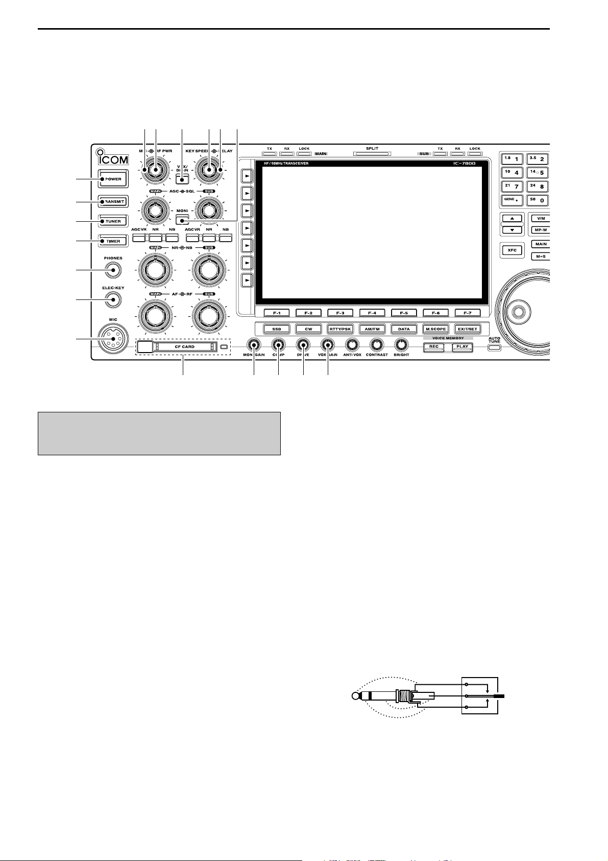
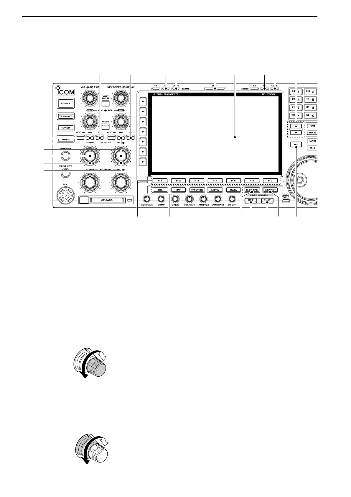
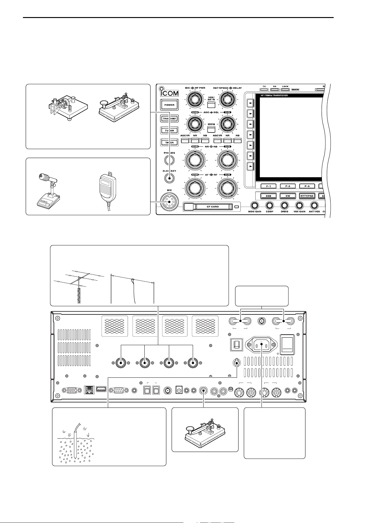
■ Front panel
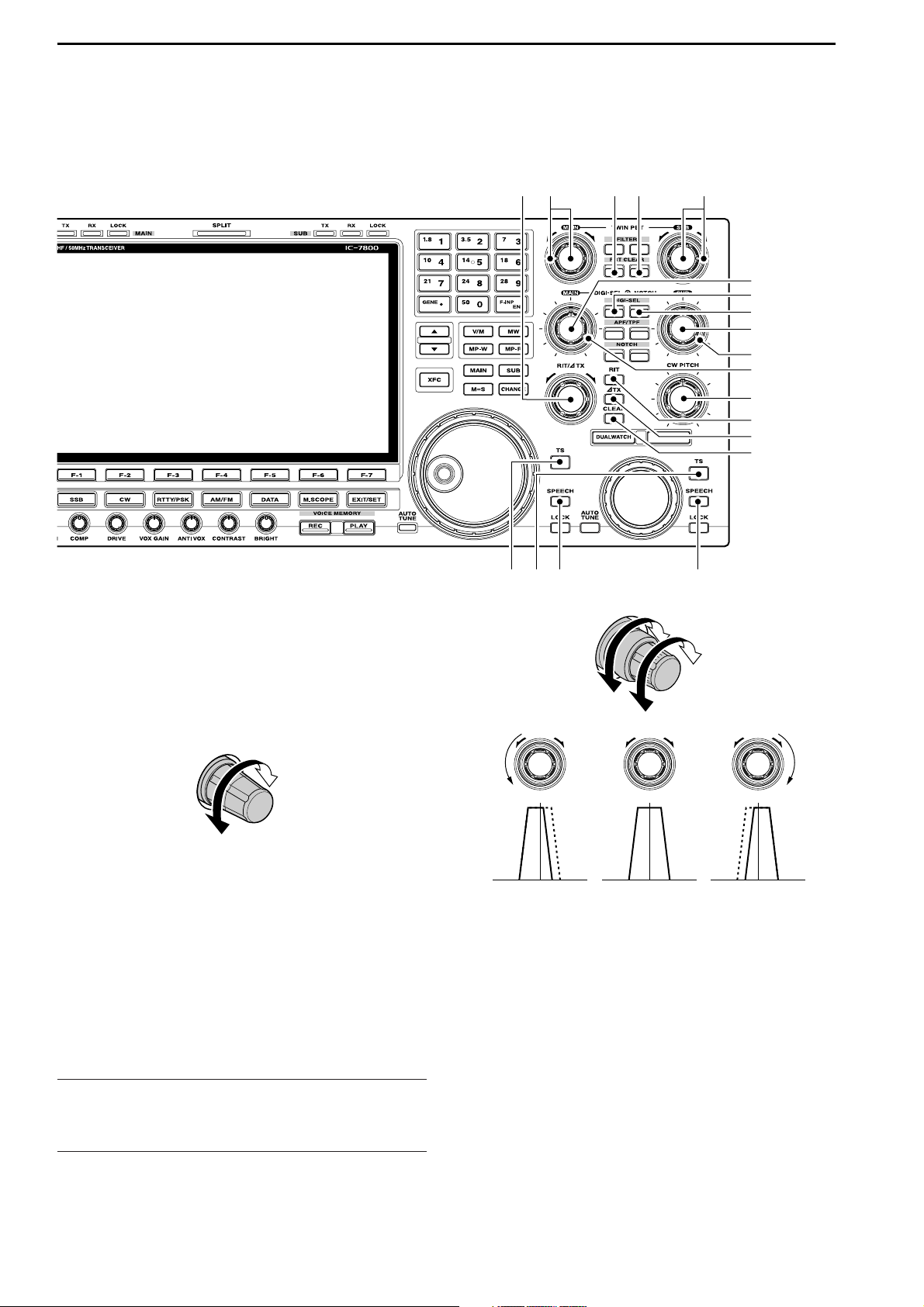
q POWER SWITCH [POWER] (p. 3-2)
➥ Push to turn the transceiver power ON.
• The [POWER] indicator above this switch lights green
when powered ON.
➥ Push for 1 sec. to turn the transceiver power
OFF.
• The [POWER] indicator lights orange when the transceiver is OFF when the internal power supply is
switched ON.
w TRANSMIT SWITCH [TRANSMIT]
Selects transmitting or receiving.
• The [TX] indicator lights red while transmitting and the
[RX] indicator lights green when the squelch is open.
e ANTENNA TUNER SWITCH [TUNER] (p. 10-5)
➥ Turns the internal antenna tuner ON and OFF
(bypass) when pushed momentarily.
• The [TUNER] indicator above this switch lights green
when the tuner is turned ON, goes off when tuner is
turned OFF (bypassed).
➥ Tunes the antenna tuner manually when pushed
for 1 sec.
• The [TUNER] indicator blinks red during manual tuning.
• When the tuner cannot tune the antenna, the tuning
circuit is bypassed automatically after 20 sec.
r TIMER SWITCH [TIMER] (p. 11-4)
➥ Turns the sleep or daily timer function ON and
OFF.
• The [TIMER] indicator above this switch lights green
when the timer is in use.
➥ Enters timer set mode when pushed for 1 sec.
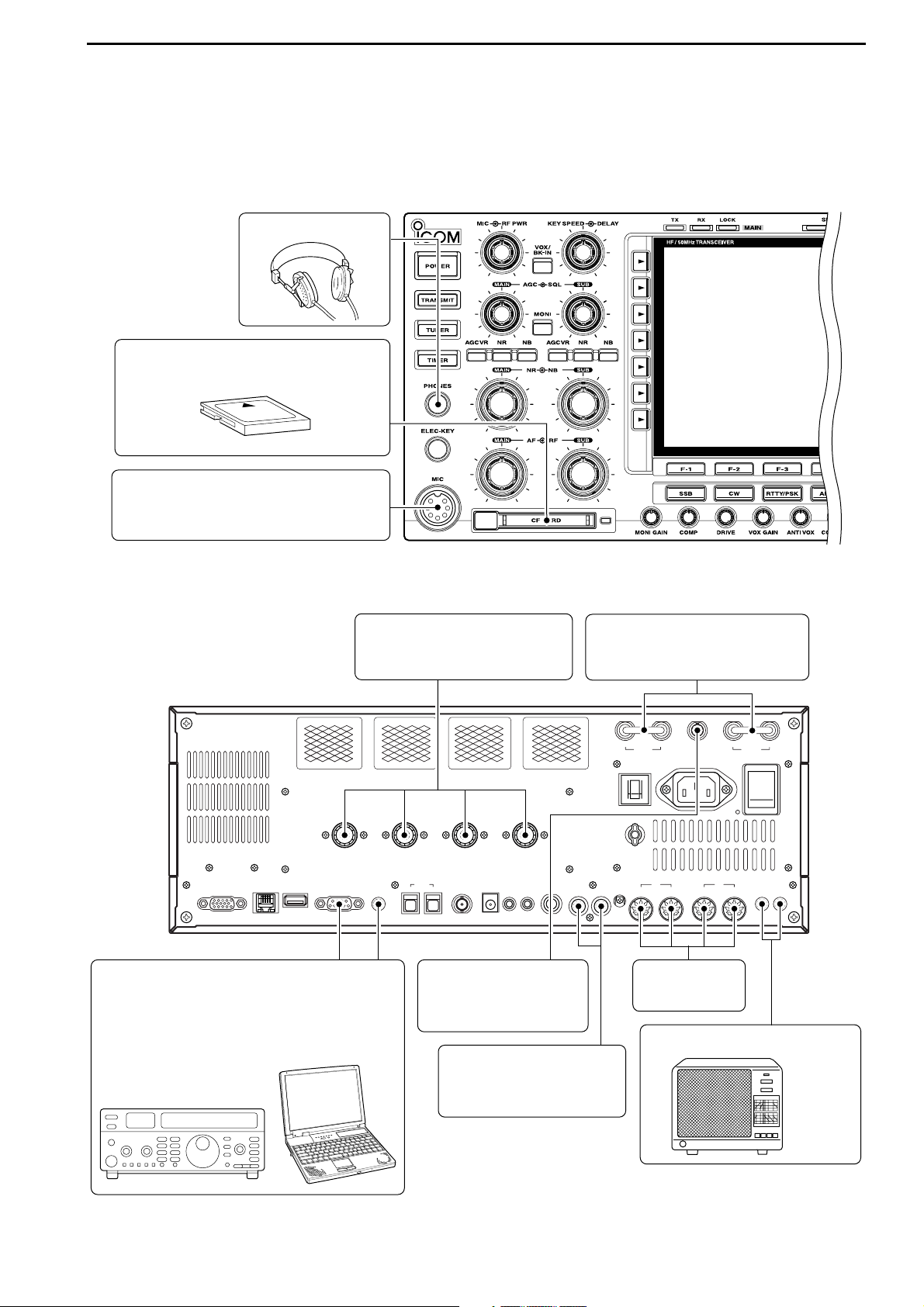
t HEADPHONE JACK [PHONES]
Accepts standard stereo headphones.
• Output power: 50 mW with an 8 Ω load.
• When headphones are connected, the internal speaker
or connected external speaker does not function.
y ELECTRONIC KEYER JACK [ELEC-KEY] (p. 2-4)
Accepts a paddle to activate the internal electronic
keyer for CW operation.
• You can select internal electronic keyer, bug-key or
straight key operation in keyer set mode. (p. 4-12)
• A straight key jack is located on the rear panel. See
[KEY] on p. 1-13.
• Keyer polarity (dot and dash) can be reversed in keyer
set mode. (p. 4-12)
• 4-channel memory keyer is available for your convenience. (p. 4-8)
u MICROPHONE CONNECTOR [MIC]
Accepts an optional microphone.
• See p. 15-4 for appropriate microphones.
• See p. 2-9 for microphone connector information.
(dot)
(com)
(dash)
Turn the internal power supply ON in advance. The
internal power supply switch is located on the rear
panel. (p. 3-2)
1
PANEL DESCRIPTION
q
w
e
r
t
y
u
io !0 !1 !2 !3
!4 !5 !6
!7 !8
Page 13
1-3
i RF POWER CONTROL [RF PWR] (p. 3-12)
Continuously varies the RF output power from minimum (5 W*) to maximum (200 W*).
*AM mode: 5 W to 50 W
o MIC GAIN CONTROL [MIC]
Adjusts microphone input gain.
• The transmit audio tone in SSB, AM and FM modes can
be adjusted independently in set mode. (p. 12-4)
✔
How to set the microphone gain.
Set the [MIC] control so that the ALC meter sometimes
swings during normal voice transmission in SSB, AM or FM
mode.
!0 VOX/BREAK-IN SWITCH [VOX/BK-IN]
➥ Push to turn the VOX function ON and OFF dur-
ing SSB, AM and FM mode operation. (p. 6-2)
➥ Push to turn the break-in function ON (semi-break-
in, full-break-in)
and OFF during CW mode opera-
tion. (p. 6-3)
➥ Push for 1 sec. to enter VOX set mode. (p. 6-2)
✔
What is the VOX function?
The VOX function (voice operated transmission) starts transmission without pushing the transmit switch or PTT switch
when you speak into the microphone; then, automatically returns to receive when you stop speaking.
✔
What is the break-in function?
The break-in function switches transmit and receive with CW
keying. Full break-in (QSK) can monitor the receive signal
during keying.
!1 ELECTRONIC CW KEYER SPEED CONTROL
[KEY SPEED] (p. 4-4)
Adjusts the internal electronic CW keyer’s speed.
• 6 wpm (min.) to 60 wpm (max.) can be set.
!2 BREAK-IN DELAY CONTROL [DELAY] (p. 6-3)
Adjusts the transmit-to-receive switching delay time
for CW semi-break-in operations.
!3 MONITOR SWITCH [MONI] (p. 6-4)
Monitors your transmitted IF signal.
• The CW sidetone functions regardless of [MONI] switch
setting in CW mode.
• The [MONI] indicator above this switch lights green
while the function is activated.
!4 MEMORY CARD SLOT [CF CARD] (p. 2-3)
Insert the supplied CF (Compact Flash) memory
card for both reading/storing a wide variety of the
transceiver’s information and data.
• The indicator beside the slot lights or blinks when the
transceiver reads or writes to the memory card.
• Push the eject button to remove the memory card.
!5 MONITOR GAIN CONTROL [MONI GAIN] (p. 6-4)
Adjusts the transmit IF signal monitor level.
!6 COMPRESSION LEVEL CONTROL [COMP]
(p. 6-5)
Adjusts the speech compression level in SSB.
!7 DRIVE GAIN CONTROL [DRIVE] (p. 3-13)
Adjusts the transmitter level at the driver stage. Activate in all modes
(except SSB with [COMP] OFF).
!8 VOX GAIN CONTROL [VOX GAIN] (p. 6-2)
Adjusts the transmit/receive switching threshold
level for VOX operation.
Low
sensitivity
High
sensitivity
Push
Decreases
Increases
Push
Compression
gain decreases
Compression
gain increases
Push
Monitor gain
decreases
Monitor gain
increases
Push
Long delay for
slow speed keying
Short delay for
high speed keying
Max.
60 wpm
Min.
6 wpm
Recommended level for
an Icom microphone
Decreases Increases
Increases
Decreases
1
PANEL DESCRIPTION
Page 14
1-4
■ Front panel (continued)
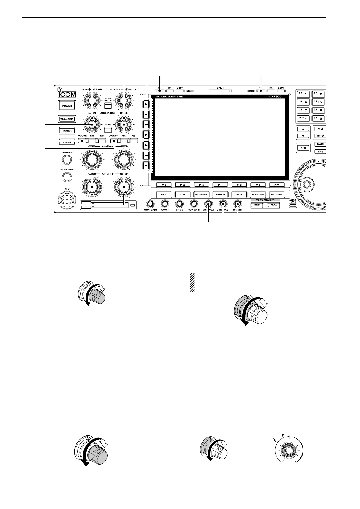
!9 AGC CONTROL [AGC] (for MAIN band; p. 5-11)
@0 AGC CONTROL [AGC] (for SUB band; p. 5-11)
Adjusts the continuously-variable AGC circuit time
constant.
• To use [AGC] control, push the appropriate band’s
[AGC VR] ([AGC VR] indicator lights).
@1 AGC VOLUME SWITCH [AGC VR]
(for MAIN band; p. 5-11)
@2 AGC VOLUME SWITCH [AGC VR]
(for SUB band; p. 5-11)
➥ Push to toggle [AGC] control usage ON and OFF.
• Use [AGC] control to set the AGC time constant when
switched ON.
• The [AGC VR] indicator above this switch lights
green when the control is ON.
➥ Turns the AGC function OFF when pushed for
1 sec.
@3 AF CONTROL [AF] (inner control; for SUB band)
@4 AF CONTROL [AF] (inner control; for MAIN band)
Varies the audio output level of the speaker or
headphones.
@5 RF GAIN CONTROL [RF] (outer control; for MAIN
band; p. 3-9)
@6 RF GAIN CONTROL [RF] (outer control; for SUB
band; p. 3-9)
Adjusts the RF gain level.
While rotating the RF gain control, you may hear
noise. This comes from the DSP unit and does
not indicate a malfunction.
@7 SQUELCH CONTROL [SQL] (outer control; for
MAIN band; p. 3-9)
@8 SQUELCH CONTROL [SQL] (outer control; for
SUB band; p. 3-9)
Adjusts the squelch threshold level. The squelch removes noise output from the speaker (closed condition) when no signal is received.
• The squelch is particularly effective for FM. It is also
available for other modes.
• 11 to 12 o’clock position is recommended for any setting of the [SQL] control.
Deep
Deep
S-meter
squelch
Noise squelch
Squelch
is open.
Squelch
threshold
Shallow
Shallow
Sensitivity
increases
Sensitivity
decreases
Audio output
increases
Audio output
decreases
Slow
Fast
1
PANEL DESCRIPTION
@6
@4
@5
@1
@2
@3
#2
!9
#0 #1@9
@0
#3 #4
@7 @8
Page 15
1-5
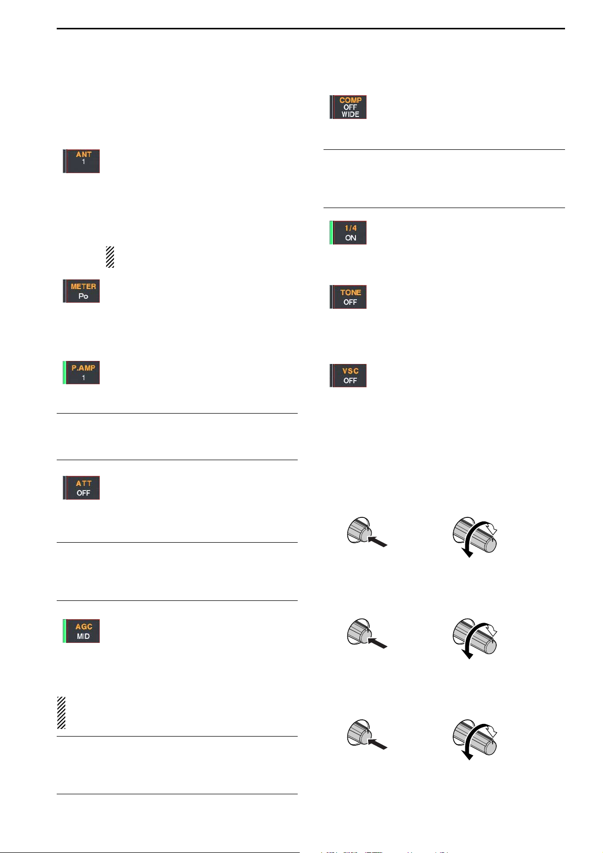
@9 MULTI-FUNCTION SWITCHES
Push to select the functions indicated in the LCD
display to the right of these switches.
• Functions vary depending on the operating condition.
➥ Selects the antenna connector from
ANT1, ANT2, ANT3 and ANT4 when
pushed. (p. 10-2)
➥ Displays antenna selection memory
when pushed for 1 sec.
• When the receive antenna is activated, the
antenna which is connected to [ANT4] is
used for receive only.
When a transverter is in use, this [ANT]
does not function and ‘TRV’ appears.
➥ Selects RF power (Po), SWR, ALC,
COMP, VD or ID metering during transmit.
(p. 3-10)
➥ Switches the multi-function digital meter
ON and OFF when pushed for 1 sec.
(p. 3-10)
➥ Selects one of 2 receive RF preamps or
bypasses them. (p. 5-9)
• “P. AMP1” activates 10 dB preamp.
•
“P. AMP2” activates 16 dB high-gain preamp.
✔
What is the preamp?
The preamp amplifies received signals in the front end circuit to improve S/N ratio and sensitivity. Select “P. AMP1” or
“P. AMP2” when receiving weak signals.
➥ Selects 6 dB, 12 dB or 18 dB attenuator
when pushed. (p. 5-9)
➥ Selects 3 dB, 6 dB, 9 dB, 12 dB, 18 dB,
or 21 dB attenuator when pushed for
1 sec. (p. 5-9)
✔
What is the attenuator?
The attenuator prevents a desired signal from distorting
when very strong signals are near the desired frequency, or
when very strong electric fields, such as from a broadcasting station, are near your location.
➥ Activates and selects fast, middle or slow
AGC time constant when pushed. (p. 5-
11)
• In FM mode, only “FAST” is available.
➥ Enters the AGC set mode when pushed
for 1 sec. (p. 5-11)
AGC time constant can be set between 0.1 to
8.0 sec.
(depends on mode), or turned OFF. When
AGC is “OFF,” the S-meter does not function.
✔
What is the AGC?
The AGC controls receiver gain to produce a constant audio
output level, even when the received signal strength varies
dramatically. Select “FAST” for tuning and then select “MID”
or “SLOW” depending on the receiving condition.
➥ Turns the speech compressor ON and
OFF in SSB mode. (p. 6-5)
➥ Switches the narrow, middle or wide
compression when pushed for 1 sec.
✔
What is the speech compressor?
The speech compressor compresses the transmitter audio
input to increase the average audio output level, to increase
talk power. This function is effective for long-distance communication or when propagation conditions are poor.
➥ Turns the 1⁄4
-speed tuning function ON
and OFF in SSB data, CW, RTTY and
PSK modes. (p. 3-6)
•1⁄4 function sets dial rotation to 1⁄4 of normal
speed for fine tuning.
➥ Switches between the tone encoder,
tone squelch function and no-tone operation when pushed in FM mode. (pgs. 432, 4-33)
➥ Enters the tone set mode when pushed
for 1 sec. in FM mode. (pgs. 4-32, 4-33)
➥ Switches the voice squelch control func-
tion ON and OFF; useful for scanning.
(p. 9-3)
#0 TRANSMIT INDICATOR [TX] (for MAIN band)
#1 TRANSMIT INDICATOR [TX] (for SUB band)
Lights red while transmitting.
• SUB band’s [TX] indicator lights only when in split operation.
#2 ANTI VOX CONTROL [ANTI VOX] (p. 6-2)
Adjusts the VOX deactivate level to prevent unwanted VOX activation from the speaker audio.
#3 LCD CONTRAST CONTROL [CONTRAST]
Adjusts the LCD contrast.
#4 LCD BRIGHTNESS CONTROL [BRIGHT]
Adjusts the LCD brightness.
Dark
Bright
Push
Low
contrast
High
contrast
Push
Decreases
cut-off level
Increases
cut-off level
Push
1
PANEL DESCRIPTION
Page 16
1-6
■ Front panel (continued)
#5 NOISE REDUCTION SWITCH [NR] (for MAIN
band; p. 5-18)
#6 NOISE REDUCTION SWITCH [NR] (for SUB band;
p. 5-18)
Push to switch the DSP noise reduction ON and
OFF.
• The [NR] indicator above this switch lights green when
the function is activated.
#7 NOISE REDUCTION LEVEL CONTROL [NR]
(inner control; for SUB band; p. 5-18)
#8 NOISE REDUCTION LEVEL CONTROL [NR]
(inner control; for MAIN band; p. 5-18)
Adjusts the DSP noise reduction level when the
noise reduction is in use. Set for maximum readability.
• To use this control, push the appropriate band’s [NR].
#9 NOISE BLANKER CONTROL [NB] (outer control;
for MAIN band; p. 5-17)
$0 NOISE BLANKER CONTROL [NB] (outer control;
for SUB band; p. 5-17)
Adjust the noise blanker threshold level.
• To use this control, push appropriate band’s [NB] switch.
$1 NOISE BLANKER SWITCH [NB] (for MAIN band;
p. 5-17)
$2 NOISE BLANKER SWITCH [NB] (for SUB band;
p. 5-17)
➥ Switches the noise blanker ON and OFF when
pushed. The noise blanker reduces pulse-type
noise such as that generated by automobile ignition systems. This function cannot be used for
FM, or non-pulse-type noise.
• The [NB] indicator above this switch lights green
while the function is activated.
➥ Enters blank-width set mode when pushed for
1 sec.
$3 RECEIVE INDICATOR [RX] (for MAIN band)
$4 RECEIVE INDICATOR [RX] (for SUB band)
Lights green while receiving a signal and when the
squelch is open.
$5
LOCK INDICATOR [LOCK] (for MAIN band; p. 5-18)
$6 LOCK INDICATOR [LOCK] (for SUB band; p. 5-18)
Lights when the dial lock function is activated.
$7 SPLIT OPERATION INDICATOR [SPLIT]
Lights during split frequency operation.
$8 LCD FUNCTION DISPLAY (p. 1-14)
Shows the operating frequency, function switch
menus, spectrum scope screen, memory channel
screen, set mode settings, etc.
Deep
Shallow
Increases
Decreases
1
PANEL DESCRIPTION
#5
#6
$1 $2
#8
#9
$5$3 $6 $9$4$7 $8
#7
$0
%0 %1 %3 %4 %6%2 %5
Page 17
1-7
$9 MEMORY UP/DOWN SWITCHES [YY]/[ZZ] (p. 8-2)
Push to select the desired memory channel.
• Memory channels can be selected both in VFO and
memory modes.
%0 LCD FUNCTION SWITCHES [F-1]–[F-7]
Push to select the function indicated in the LCD display above these switches.
• Functions vary depending on the operating condition.
%1 MODE SWITCHES
Selects the desired mode. (p. 3-8)
• Announces selected mode via the speech synthesizer.
(p. 12-16)
➥ Selects USB and LSB modes alternately.
➥ Selects CW and CW-R (CW reverse)
modes alternately.
➥ Switches between RTTY and PSK
mode.
➥ Switches RTTY and RTTY-R (RTTY re-
verse)
mode when pushed for 1 sec. in
RTTY mode.
➥ Switches PSK and PSK-R (PSK reverse)
mode when pushed for 1 sec. in PSK
mode.
➥ Selects AM and FM modes alternately.
➥ Selects SSB, AM or FM data mode
(USB-
D, LSB-D, AM-D, FM-D)
when pushed in
SSB, AM or FM mode, respectively.
➥ Switches D1, D2 and D3 when pushed
for 1 sec.
%2 MINI SPECTRUM SCOPE SWITCH [M.SCOPE]
(p. 5-4)
Turns the mini spectrum scope screen ON and OFF.
• The mini spectrum scope screen can be displayed with
another screen, such as memory or set mode screen,
simultaneously.
%3 VOICE MEMORY RECORD SWITCH [REC]
(p. 7-3)
➥ Records the received signal for the preset time
period when pushed.
• After the preset time has passed, stops recording automatically.
➥ Records the received signal until cancelling the
record when pushed for 1 sec.
• Push this switch momentarily to stops recording.
• The memory records the latest 30 sec. of audio.
%4 VOICE MEMORY PLAY BACK SWITCH [PLAY]
(p. 7-4)
➥ Plays back the previously recorded audio for the
preset time period when pushed.
➥ Plays back all of the previously recorded audio
when pushed for 1 sec.
%5 EXIT/SET SWITCH [EXIT/SET]
➥ Push to exit, or return to the previous screen in-
dication during spectrum scope, memory, scan or
set mode screen display.
➥ Displays set mode menu screen when pushed
for 1 sec.
%6 TRANSMIT FREQUENCY CHECK SWITCH [XFC]
(p. 6-6)
Monitors the transmit frequency (including ∂TX fre-
quency offset)
when pushed and held during split fre-
quency operation.
• While pushing this switch, the transmit frequency can be
changed with the main dial, keypad, memo pad or
[Y]/[Z] switches.
• When the split lock function is turned ON, pushing [XFC]
cancels the dial lock function. (p. 6-7)
1
PANEL DESCRIPTION
Page 18
1-8
■ Front panel (continued)
%7 MEMO PAD-WRITE SWITCH [MP-W] (p. 8-7)
Programs the selected readout frequency and operating mode into a memo pad.
• The 5 most recent entries remain in memo pads.
• The memo pad capacity can be expanded from 5 to 10
in set mode. (p. 12-16)
%8 VFO/MEMORY SWITCH [V/M]
➥ Switches the selected readout operating mode
between the VFO and memory when pushed.
(pgs. 3-3, 8-2)
➥ Transfers the memory contents to VFO when
pushed for 1 sec. (p. 5-5)
%9 KEYPAD
➥ Pushing a key selects the operating band.
• [GENE•.] selects the general coverage band.
➥ Pushing the same key 2 or 3 times calls up other
stacked frequencies in the band. (p. 3-4)
• Icom’s triple band stacking register memorizes 3 frequencies in each band.
➥ After pushing [F-INP•ENT], enters a frequency or
memory channel. Pushing [F-INP•ENT] or [Y/[Z]
is necessary to end. (pgs. 3-5, 8-2)
• e.g. to enter 14.195 MHz, push [F-INP] [1.8•1] [10•4]
[GENE •] [1.8•1] [28•9] [14•5] [F-INP•
ENT].
^0 MEMORY WRITE SWITCH [MW] (p. 8-4)
Stores the selected readout frequency and operating mode into the displayed memory channel when
pushed for 1 sec.
• This function is available both in VFO and memory
modes.
^1 MEMO PAD-READ SWITCH [MP-R] (p. 8-7)
Each push calls up a frequency and operating mode
in a memo pad. The 5 (or 10) most recently programmed frequencies and operating modes can be
recalled, starting from the most recent.
• The memo pad capacity can be expanded from 5 to 10
in set mode. (p. 12-16)
^2
FILTER SWITCH [FILTER] (for MAIN band; p. 5-13)
^3 FILTER SWITCH [FILTER] (for SUB band; p. 5-13)
➥ Selects one of 3 IF filter settings.
➥ Enters the filter set screen when pushed for
1 sec.
^4 AUDIO PEAK FILTER/TWIN PEAK FILTER
SWITCH [APF/TPF] (for MAIN band)
^5 AUDIO PEAK FILTER/TWIN PEAK FILTER
SWITCH [APF/TPF] (for SUB band)
➥ Push to turn the audio peak filter ON and OFF
during CW mode operation. (p. 4-6)
➥ Push to turn the twin peak filter ON and OFF dur-
ing RTTY mode operation. (p. 4-14)
• “ ” appears when audio peak filter is in use.
• “ ” appears when twin peak filter is in use.
➥ During CW mode operation, push for 1 sec. to
select the APF passband width from 80, 160 and
320 Hz. (p. 4-6)
TPF
APF
1
PANEL DESCRIPTION
%7 %8 ^0 ^1%9
&0 &8&1 &5&4&2 &6 &3 &7&9
^2 ^3
^5
^4
^6
^7
^9
^8
Page 19

1-9
^6 NOTCH SWITCH [NOTCH] (for SUB band; p. 5-19)
^7
NOTCH SWITCH [NOTCH] (for MAIN band; p. 5-19)
➥ Switches the notch function between auto, man-
ual and OFF in SSB and AM modes.
➥ Turns the manual notch function ON and OFF
when pushed in CW, RTTY and PSK31 mode.
➥ Turns the auto notch function ON and OFF when
pushed in FM mode.
• “ ” appears when auto notch is in use.
• “ ” appears when manual notch is in use.
➥ Switches the manual notch characteristics from
wide, middle and narrow when pushed for 1 sec.
✔
What is the notch function?
The notch function eliminates unwanted CW or AM carrier
tones while preserving the desired voice signal. The DSP circuit automatically adjusts the filtering frequency to effectively
eliminate unwanted tones.
^8 DUALWATCH SWITCH [DUALWATCH] (p. 5-16)
➥ Turns the dualwatch function ON and OFF when
pushed.
➥ Turns the dualwatch function ON and equalizes
the main/sub readout frequency to the sub/main
readout when pushed for 1 sec.
(Quick dualwatch
function)
• The quick dualwatch function can be turned OFF
using set mode. (p. 12-14)
^9 SPLIT SWITCH [SPLIT] (p. 6-6)
➥ Turns the split function ON and OFF when
pushed.
➥ Turns the split function ON. When pushed for
1 sec. in non-FM modes, equalizes the sub readout frequency to the main readout and sets the
sub readout for frequency input. (Quick split func-
tion)
• The offset frequency is shifted from the main readout
frequency in FM mode. (p. 12-15)
• The quick split function can be turned OFF using set
mode. (p. 12-15)
➥ Turns the split function ON and shifts the sub
readout frequency after inputting an offset.
&0 MAIN BAND ACCESS SWITCH [MAIN]
Selects the main readout.
• The main readout frequency is clearly displayed. The
sub readout functions only during split operation or dualwatch.
&1 MAIN/SUB EQUALIZING SWITCH [M=S]
Equalizes the sub readout frequency to the main
readout frequency when pushed for 1 sec.
&2 AUTOMATIC TUNING SWITCH [AUTO TUNE]
(for MAIN band)
&3 AUTOMATIC TUNING SWITCH [AUTO TUNE]
(for SUB band)
Turns the automatic tuning function ON and OFF in
CW and AM modes.
&4 MAIN DIAL
Changes the displayed frequency (main band), selects set mode setting, etc.
&5 MAIN/SUB CHANGE SWITCH [CHANGE]
Switches the frequency and selected memory
channel between main and sub readouts when
pushed.
• Switches between transmit frequency and receive frequency when the split frequency function is ON. (p. 6-6)
&6 LOCK SWITCH [LOCK] (for MAIN band; p. 5-18)
&7 LOCK SWITCH [LOCK] (for SUB band; p. 5-18)
Push to switch the dial lock function ON and OFF.
&8 SUB BAND ACCESS SWITCH [SUB]
Selects the sub readout.
• The sub readout frequency is clearly displayed. The
main readout functions only during split operation or dualwatch.
&9 SUB DIAL
Changes the displayed frequency in sub band.
IMPORTANT!
When receiving a weak signal, or receiving a signal with interference, the automatic tuning function may tune the receiver to an undesired signal.
1
PANEL DESCRIPTION
Page 20
1-10
■ Front panel (continued)
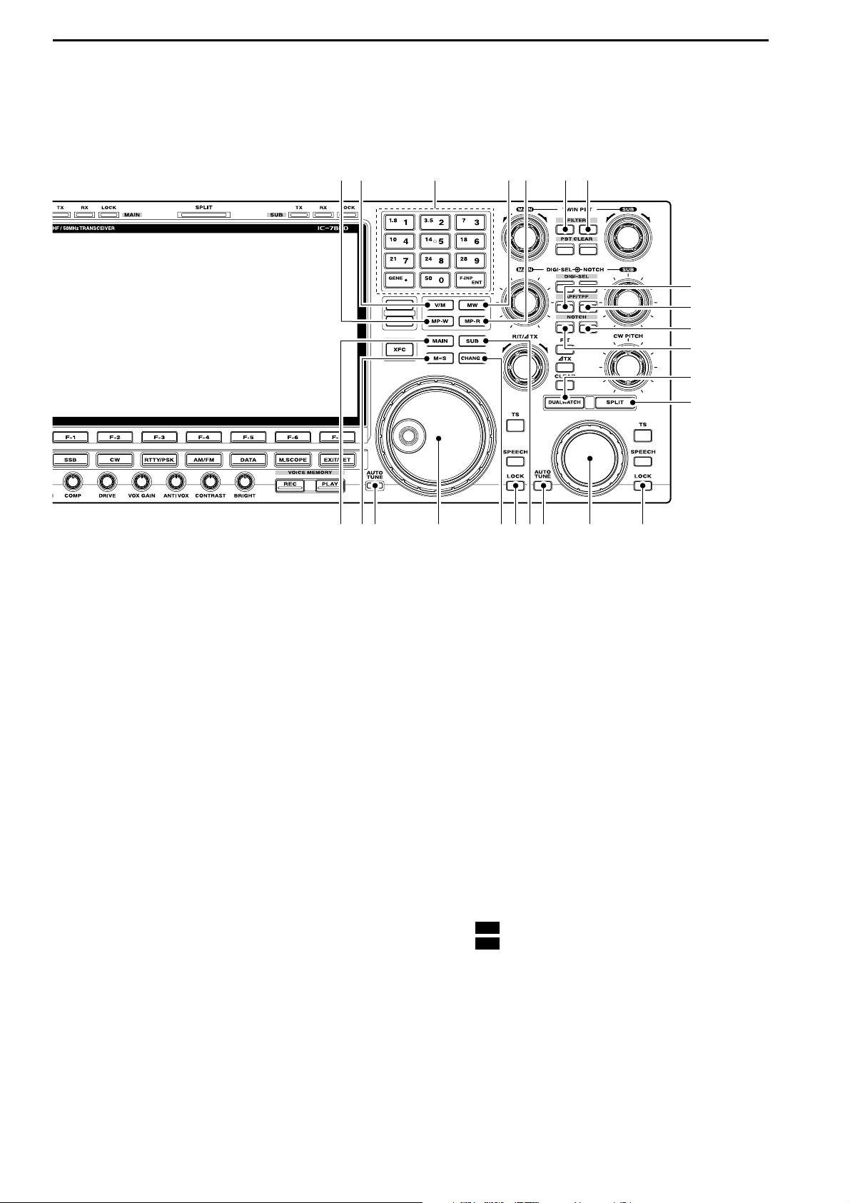
*0 RIT/∂∂TX CONTROL [RIT/∂∂TX] (pgs. 5-10, 6-4)
Shifts the receive and/or transmit frequency without
changing the transmit and/or receive frequency.
• Rotate the control clockwise to increase the frequency,
or rotate the control counterclockwise to decrease the
frequency. The RIT or ∂TX functions must be ON.
• The shift frequency range is ±9.999 kHz in 1 Hz steps
(or ±9.99 kHz in 10 Hz steps).
*1 PASSBAND TUNING CONTROLS [TWIN PBT]
(for MAIN band; p. 5-12)
*2 PASSBAND TUNING CONTROLS [TWIN PBT]
(for SUB band; p. 5-12)
Adjusts the receiver’s IF filter “passband width” via
the DSP.
• Passband width and shift frequency are displayed in the
multi-function display.
• Push [PBT CLEAR] for 1 sec. to clear the PBT settings.
• Variable range is set to half of the IF filter passband
width. 25 Hz steps and 50 Hz steps are available.
✔
What is the PBT control?
The PBT function electronically modifies the IF passband
width to reject interference. This transceiver uses the DSP
circuit for the PBT function.
*3 PBT CLEAR SWITCH [PBT CLEAR]
(for MAIN band; p. 5-12)
*4 PBT CLEAR SWITCH [PBT CLEAR]
(for SUB band; p. 5-12)
Clears the PBT settings when pushed for 1 sec.
• The [PBT CLEAR] indicator above this switch lights
when PBT is in use.
PBT1
PBT2
Low cutHigh cut Center
–+
Frequency
increases
Frequency
decreases
1
PANEL DESCRIPTION
*0
(5 (6 (7 (8
*3*1 *2*4
*8
*7
*9
(0
(2
(3
(4
*6
*5
(1
Page 21
1-11
*5 DIGITAL RF SELECTOR CONTROL [DIGI-SEL]
(for MAIN band; p. 5-19)
*6 DIGITAL RF SELECTOR CONTROL [DIGI-SEL]
(for SUB band; p. 5-19)
Adjusts the digital RF selector center frequency.
• The control can be reassigned as the audio peak filter
adjustment (p. 12-18)
*7 DIGITAL RF SELECTOR SWITCH [DIGI-SEL]
(for MAIN band; p. 5-19)
*8 DIGITAL RF SELECTOR SWITCH [DIGI-SEL]
(for SUB band; p. 5-19)
Turns the digital RF preselector ON and OFF.
• The [DIGI-SEL] indicator lights green when the preselector is in use.
*9 MANUAL NOTCH FILTER CONTROL [NOTCH]
(for SUB band; outer control; p. 5-19)
(0 MANUAL NOTCH FILTER CONTROL [NOTCH]
(for MAIN band; outer control; p. 5-19)
Varies the “valley” frequency of the manual notch filter to reject an interfering signal while the manual
notch function is ON.
• Notch filter center frequency:
SSB : –1060 Hz to 4040 Hz
CW : CW pitch freq. + 2540 Hz to CW pitch freq.
–2540 Hz
AM : –5100 Hz to 5100 Hz
(1 CW PITCH CONTROL [CW PITCH] (p. 4-5)
Shifts the received CW audio pitch and the CW side
tone pitch without changing the operating frequency.
(2 RIT SWITCH [RIT] (p. 5-10)
➥ Turns the RIT function ON and OFF when
pushed.
• Use [RIT/∂TX] control to vary the RIT frequency.
➥ Adds the RIT shift frequency to the operating fre-
quency when pushed for 1 sec.
✔
What is the RIT function?
Receiver incremental tuning (RIT) shifts the receive frequency without shifting the transmit frequency.
This is useful for fine tuning stations calling you on off-frequency or when you prefer to listen to slightly differentsounding voice characteristics, etc.
(3∂∂TX SWITCH [∂∂TX] (p. 6-4)
➥ Turns the ∂TX function ON and OFF when
pushed.
• Use [RIT/∂TX] control to vary the ∂TX frequency.
➥ Adds the ∂TX shift frequency to the operating
frequency when pushed for 1 sec.
✔
What is the ∂∂TX function?
∂TX shifts the transmit frequency without shifting the receive
frequency. This is useful for simple split frequency operation
in CW, etc.
(4 CLEAR SWITCH [CLEAR] (pgs. 5-10, 6-4)
Clears the RIT/∂TX shift frequency when pushed
for 1 sec. or when pushed momentarily, depending
on the quick RIT/∂TX clear function setting
(p. 12-
17)
.
(5 QUICK TUNING SWITCH [TS] (for MAIN band)
(6 QUICK TUNING SWITCH [TS] (for SUB band)
➥ Turns the quick tuning step ON and OFF. (p. 3-
6)
• While the quick tuning indicator, “Z,” is displayed
above the frequency indication, the frequency can be
changed in programmed kHz steps.
• 0.1, 1, 5, 9, 10, 12.5, 20 and 25 kHz steps are available for each operating mode independently.
➥ When the quick tuning step is OFF, push for
1 sec. to turn the 1 Hz tuning step ON and OFF.
(p. 3-7)
➥ When the quick tuning step is ON, push for
1 sec. to enter quick tuning step set mode. (p. 3-
6)
(7 SPEECH SWITCH [SPEECH]
(for MAIN band; p. 13-3)
(8 SPEECH SWITCH [SPEECH]
(for SUB band; p. 13-3)
➥ Push to announce the S-meter indication and the
selected readout frequency.
➥ The selected operating mode is additionally an-
nounced when pushed for 1 sec.
High
frequency
Low
frequency
Higher
frequency
Lower
frequency
Higher
frequency
Lower
frequency
1
PANEL DESCRIPTION
Page 22
1-12
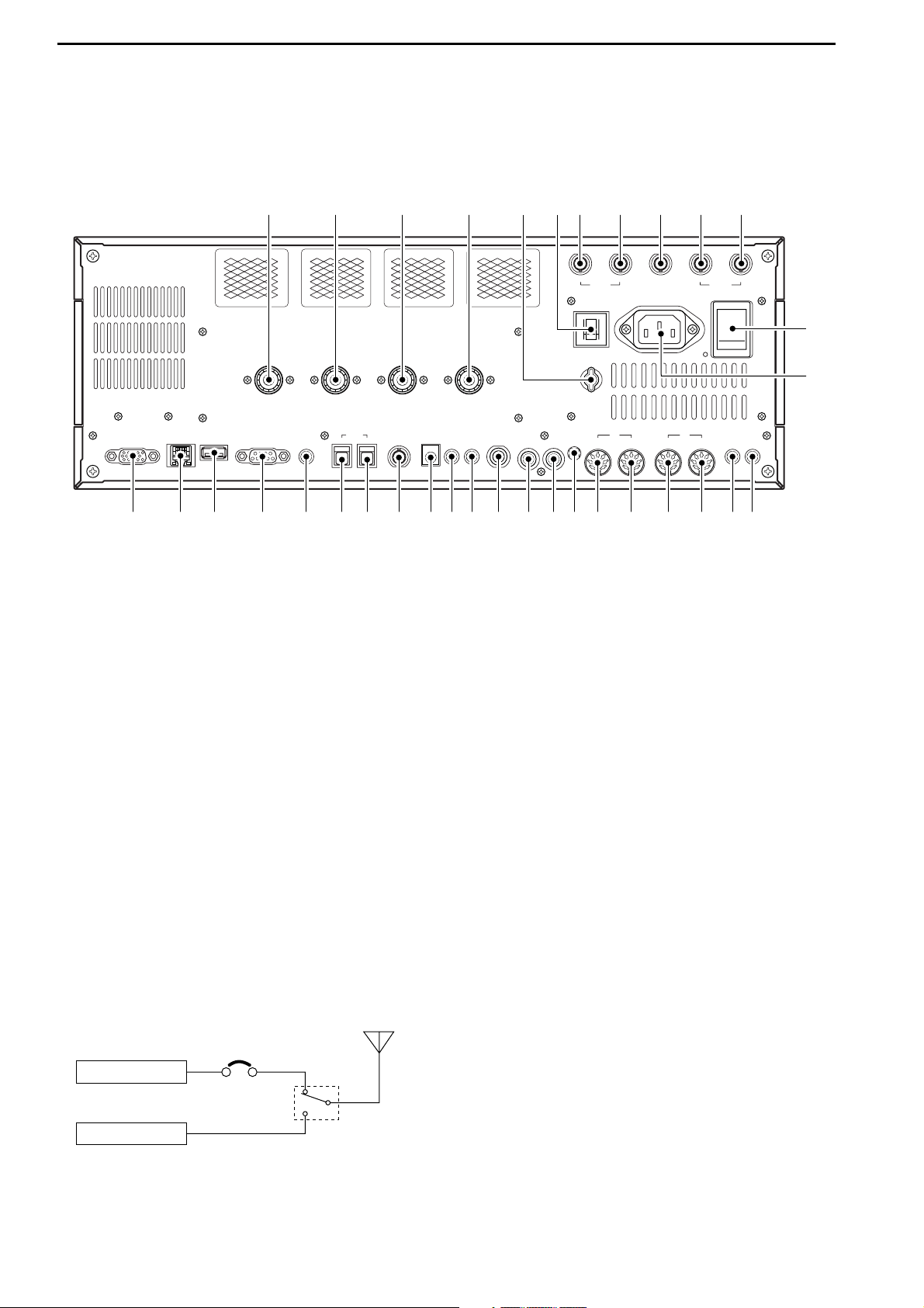
■ Rear panel
q ANTENNA CONNECTOR 1 [ANT 1] (p. 2-4)
w ANTENNA CONNECTOR 2 [ANT 2] (p. 2-4)
e ANTENNA CONNECTOR 3 [ANT 3] (p. 2-4)
r ANTENNA CONNECTOR 4 [ANT 4] (p. 2-4)
Accept a 50 Ω antenna with a PL-259 plug connector.
t GROUND TERMINAL [GND] (p. 2-3)
Connect this terminal to a ground to prevent electrical shocks, TVI, BCI and other problems.
y CIRCUIT BREAKER
Cuts off the AC input when over-current occurs.
u RECEIVE ANTENNA B OUT [RX ANT B– OUT]
i RECEIVE ANTENNA B IN [RX ANT B– IN]
Located between the transmit/receive switching circuit and receiver’s RF stage in SUB band (MAIN
band during split operation).
Connects an external unit, such as preamplifier or
RF filter, using BNC connectors, if desired.
When no external unit is connected, [RX ANT B–
OUT] and [RX ANT B– IN] must be shorted with the
supplied coaxial cable. (p. 2-2)
o TRANSVERTER CONNECTOR [X-VERTER]
(p. 2-5)
External transverter input/output connector.
Activated by voltage applied to [ACC 2] pin 6, or
when the transverter function is in use. (pgs. 2-10,
4-6)
!0 RECEIVE ANTENNA A OUT [RX ANT A– OUT]
!1 RECEIVE ANTENNA A IN [RX ANT A– IN]
Located between the transmit/receive switching circuit and receiver’s RF stage in MAIN band (SUB
band during split operation).
Connects an external unit, such as preamplifier or
RF filter, using BNC connectors, if desired.
When no external unit is connected, [RX ANT A–
OUT] and [RX ANT A– IN] must be shorted with the
supplied coaxial cable. (p. 2-2)
!2 MAIN POWER SWITCH [I/O] (p. 3-2)
Turns the internal power supply ON and OFF.
!3 AC POWER SOCKET [AC] (p. 2-4)
Connects the supplied AC power cable to an AC
line-voltage receptacle.
!4
EXTERNAL SPEAKER JACK MAIN [EXT-SP MAIN]
(p. 2-5)
!5 EXTERNAL SPEAKER JACK SUB [EXT-SP SUB]
(p. 2-5)
Connects an external speaker (4–8 Ω), if desired.
Receiver
Transmitter
IN
[RX ANT A/B]
OUT
Transmit/Receive
switching circuit
1
PANEL DESCRIPTION
MAINSUB
ACC 1
ACC 2
ACC 1
ACC 2
ALC
ADJ
ALC
RELAY
KEY
EXT
KEYPAD
METER
DC OUT
15V
MAX1A
REF I/O
10MHz
-
10dBm
INOUT
REMOTE
RS
-
232C
KEY BOARD
EXT-DISPLAY
A
B
S/P DIF
EXT-SP
ANT 1
ANT 2
ANT 3
ANT 4
GND
AC
I
X-VERTER
A
IN
RX ANT
B
RX ANT
OUT
IN
OUT
q w e r u i o !0 !1
!4!5!7!9 !6!8@0@1@2@3@4@5@6@7@8@9#0#1#2#3 #4
!2
!3
t y
Page 23
1-13
!6 ACCESSORY SOCKET 1 A [ACC 1–A]
!7 ACCESSORY SOCKET 2 A [ACC 2–A]
!8 ACCESSORY SOCKET 1 B [ACC 1–B]
!9 ACCESSORY SOCKET 2 B [ACC 2–B]
Enable connection of external equipment such as a
linear amplifier, an automatic antenna
selector/tuner, a TNC for data communications, etc.
• See p. 2-10 for socket information.
@0 ALC LEVEL ADJUSTMENT POT [ALC ADJ]
Adjusts the ALC levels.
No adjustment is required when the ALC output
level of the connected non-Icom linear amplifier is
0 to –4 V DC.
@1 ALC INPUT JACK [ALC] (p. 2-7)
Connects to the ALC output jack of a non-Icom linear amplifier.
@2 T/R CONTROL JACK [RELAY] (p. 2-7)
Goes to ground when transmitting to control an external unit, such as a non-Icom linear amplifier.
@3 STRAIGHT KEY JACK [KEY] (p. 2-4)
Accepts a straight key or external electronic keyer
with 1⁄4 inch standard plug.
• [ELEC-KEY] on the front panel can be used for a
straight key or external electronic keyer. Deactivate the
internal electronic keyer in keyer set mode. (p. 4-12)
@4 EXTERNAL KEYPAD JACK [EXT KEYPAD]
(p. 2-6)
Connects an external keypad for direct voice memory or electronic keyer control.
Transceiver mute control line (both transmit and receive) is also supported.
@5 METER JACK [METER] (p. 2-6)
Outputs the receiving signal strength level signal,
transmit output power, VSWR, ALC, speech compression, VD or ID level for external meter indication.
@6 DC OUTPUT JACK [DC OUT] (p. 2-6)
Outputs a regulated 14 V DC (approx.) for external
equipment. Connected in parallel with 13.8 V outputs of [ACC 1] and [ACC 2]. (max. 1 A in total)
@7 REFERENCE SIGNAL INPUT/OUTPUT
TERMINAL [REF I/O]
Inputs/outputs a 10 MHz reference signal.
@8 S/P DIF INPUT TERMINAL [S/P DIF– IN] (p. 2-6)
@9 S/P DIF OUTPUT TERMINAL [S/P DIF– OUT]
(p. 2-6)
Connects external equipment that supports S/P DIF
input/output.
#0 CI-V REMOTE CONTROL JACK [REMOTE]
(p. 2-5)
➥ Connects a PC via the optional CT-17
CI-V LEVEL
CONVERTER for external control of the transceiver.
➥ Used for transceive operation with another Icom
CI-V transceiver or receiver.
#1 RS-232C TERMINAL [RS-232C] (p. 2-5)
Connects an RS-232C cable, D-sub 9-pin to connect the IC-7800 to a PC.
Can be used for remotely control the IC-7800 without the optional CT-17, or for RTTY/PSK31 decoded signal output. The [RS-232C] interface is
wired as a modem (DCE).
#2 KEYBOARD CONNECTOR [KEYBOARD]
(p. 2-6)
Connects a PC keyboard for RTTY and PSK31 operations.
• USB (Universal Serial Bus) keyboard is supported.
#3 EXTERNAL DISPLAY TERMINAL
[EXT-DISPLAY] (p. 2-6)
Connects to an external display monitor.
• At least 800×600 pixel display is necessary.
#4 ETHERNET CONNECTOR (p. 16-6)
Connects to a PC through a LAN (Local Area Network).
+
_
_
(+)
(_)
NOTE: T/R control voltage and current must be
lower than 16 V DC/0.5 A (or 250 V AC,
200 mA with MOS-FET switching).
1
PANEL DESCRIPTION
Page 24
■ LCD display
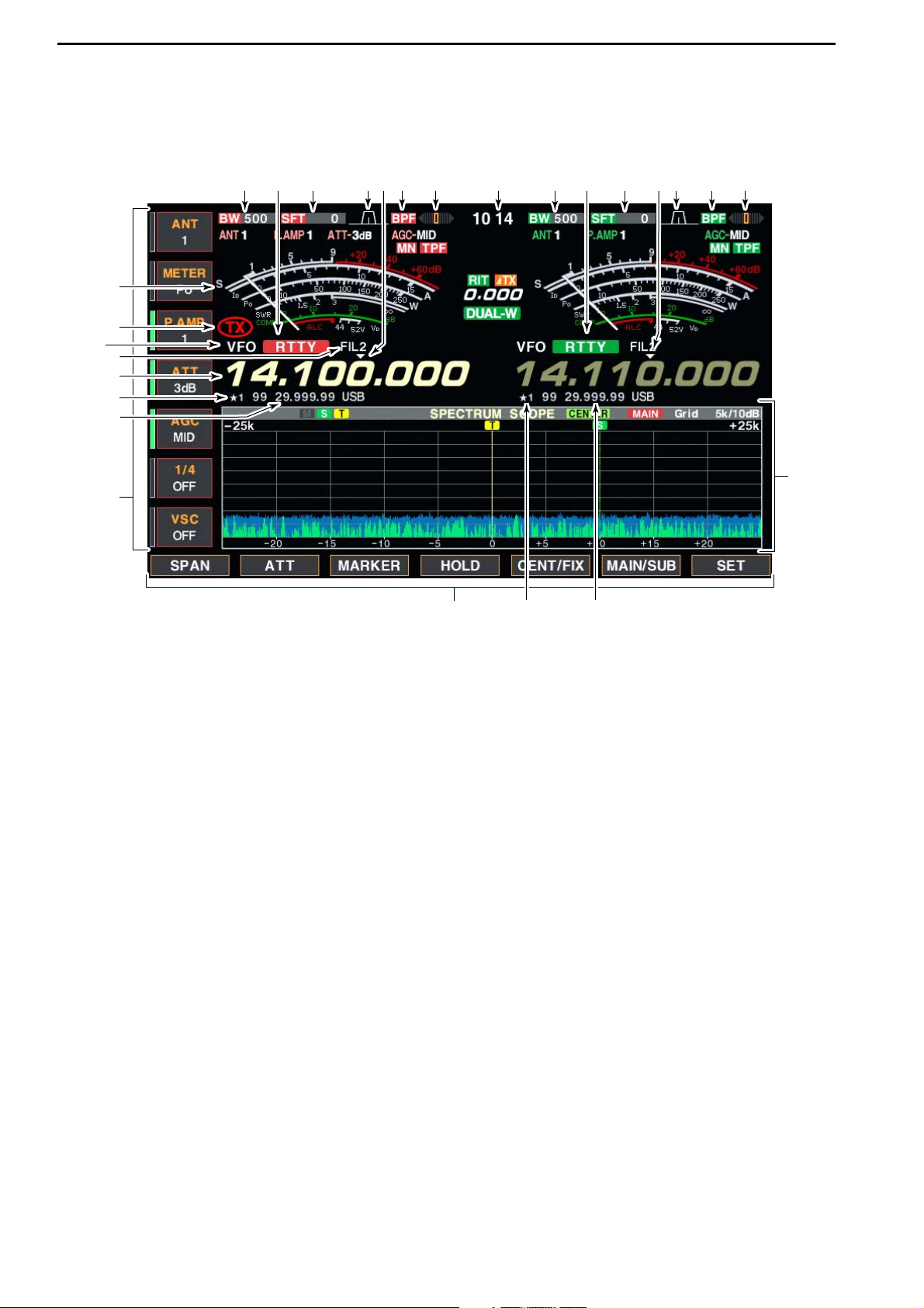
q BAND WIDTH INDICATOR (p. 5-12)
Shows the passband width of the IF filter.
w MODE INDICATOR
Shows the selected mode.
e SHIFT FREQUENCY INDICATOR (p. 5-12)
Shows the shift frequency of the IF filter.
r QUICK TUNING INDICATOR (p. 3-6)
Appears when the quick tuning step function is in use.
t PASSBAND WIDTH INDICATOR (p. 5-12)
Graphically displays the passband width for twin
PBT operation and center frequency for IF shift operation.
y BANDPASS FILTER INDICATOR
Appears when the narrow filter (500 Hz or less) is
selected during CW, RTTY or PSK31 operation.
u RTTY TUNING INDICATOR
Shows the tuning level in RTTY mode.
i CLOCK READOUT
Shows the current time.
o S/RF METER (p. 3-10)
Shows the signal strength while receiving. Shows
the relative output power, SWR, ALC or compression levels while transmitting.
!0 TX INDICATOR
Indicates the frequency readout for transmit.
!1 VFO/MEMORY CHANNEL INDICATOR (p. 3-3)
Indicates the VFO mode or selected memory channel number.
!2 IF FILTER INDICATOR
Shows the selected IF filter number.
!3 FREQUENCY READOUTS
Shows the operating frequency.
• Gray characters are used for non-active readout.
!4
SELECT MEMORY CHANNEL INDICATOR (p. 9-7)
Indicates the displayed memory channel is set as a
select memory channel.
!5 MEMORY CHANNEL READOUTS
➥ Shows the selected memory channel contents in
VFO mode.
➥ Shows the VFO contents in memory mode.
!6 MULTI-FUNCTION SWITCH GUIDE
Indicates the function of the multi-function switches.
!7 LCD FUNCTION SWITCH GUIDE
Indicates the function of the LCD function switches
([F-1] – [F-7]).
!8 MULTI-FUNCTION SCREEN
Shows the screens for the multi-function digital
meter, spectrum scope, voice recorder, memory
channel, scan, memory keyer, RTTY decoder, PSK
decoder, IF filter selection or set modes, etc.
1-14
1
PANEL DESCRIPTION
q w e t uy ir q w e t uyr
!7
!4 !5
!6
!4
!5
!3
!2
!1
!0
o
!8
Page 25
1-15
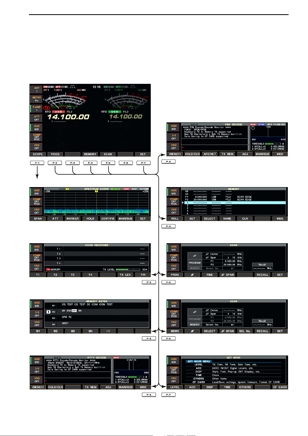
■ Screen menu arrangement
The following screens can be selected from the start
up screen. Choose the desired screen using the following chart.
Pushing [EXIT/SET] several times returns to the start
up screen. See p. 12-3 for set mode arrangement.
1
PANEL DESCRIPTION
• Spectrum scope screen (p. 5-2)
• Voice recorder screen (p. 7-3)
• RTTY decoder screen (p. 4-13)
• Memory keyer screen (CW mode; p. 4-8)
• Memory channel screen (p. 8-3)
• PSK31 decoder screen (p. 4-21)
• Scan screen (VFO mode; p. 9-4)
• Scan screen (Memory mode; p. 9-6)
• Set mode menu screen (p. 12-2)
Page 26

2-1
INSTALLATION AND CONNECTIONS Section 2
■ Unpacking ……………………………………………………………… 2-2
■ Antenna jumper cable connection …………………………………… 2-2
■ Selecting a location …………………………………………………… 2-2
■ Rack mounting handle attachment …………………………………… 2-2
■ Grounding ……………………………………………………………… 2-3
■ Antenna connection …………………………………………………… 2-3
■ CF (Compact Flash) memory card …………………………………… 2-3
■ Required connections ………………………………………………… 2-4
D Front panel …………………………………………………………… 2-4
D Rear panel …………………………………………………………… 2-4
■ Advanced connections ………………………………………………… 2-5
D Front panel …………………………………………………………… 2-5
D Rear panel—1 ……………………………………………………… 2-5
D Rear panel—2 ……………………………………………………… 2-6
■ Linear amplifier connections …………………………………………… 2-7
D Connecting the IC-PW1 …………………………………………… 2-7
D Connecting a non-Icom linear amplifier …………………………… 2-7
■ Transverter jack information …………………………………………… 2-8
■ FSK and AFSK (SSTV) connections ………………………………… 2-8
■ Microphone connector information …………………………………… 2-9
■ Microphones (options) ………………………………………………… 2-9
D SM-20 ………………………………………………………………… 2-9
D HM-36 ………………………………………………………………… 2-9
■ Accessory connector information …………………………………… 2-10
CAUTION!: The transceiver weighs approx. 25 kg (55 lb).
Always have two people available to carry, lift or
turn over the transceiver.
Page 27
2-2
■ Unpacking
After unpacking, immediately report any damage to the
delivering carrier or dealer. Keep the shipping cartons.
For a description and a diagram of accessory equipment included with the IC-7800, see ‘Supplied accessories’ on p. iii of this manual.
■ Antenna jumper cable connection
Connect the supplied coaxial cable (terminated with
BNC connectors) between [RX ANT A— IN] and [RX
ANT A— OUT], and, [RX ANT B— IN] and [RX ANT
B— OUT], respectively.
When connecting an external filter unit, pre-amplifier,
etc., connect the unit between [RX ANT A/B— IN] and
[RX ANT A/B— OUT] connectors.
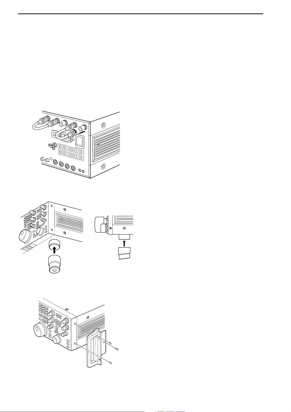
■ Selecting a location
Select a location for the transceiver that allows adequate air circulation, free from extreme heat, cold, or
vibrations, and away from TV sets, TV antenna elements, radios and other electromagnetic sources.
The base of the transceiver has an adjustable stand
for desktop use. Set the stand to one of two angles depending on your operating preference.
■ Rack mounting handle attachment
Remove the four screws from both sides of the front
panel and the two screws from both sides of the side
panel, then attach the rack mounting handles to the
sides of the transceiver using the supplied screws.
2
INSTALLATION AND CONNECTIONS
Page 28
2-3
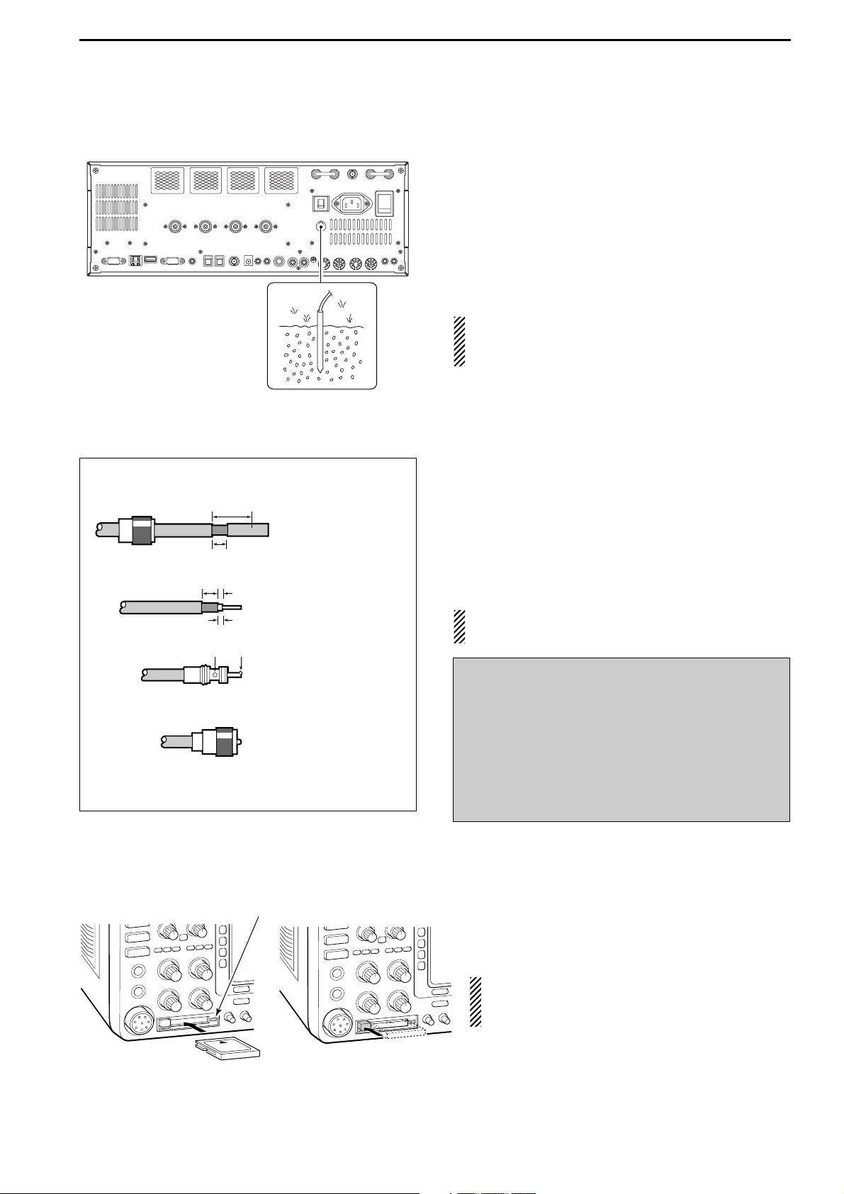
■ Grounding
To prevent electrical shock, television interference
(TVI), broadcast interference (BCI) and other problems, ground the transceiver through the GROUND
terminal on the rear panel.
For best results, connect a heavy gauge wire or strap
to a long earth-sunk copper rod. Make the distance between the [GND] terminal and ground as short as possible.
R WARNING: NEVER connect the [GND]
terminal to a gas or electric pipe, since the connection could cause an explosion or electric shock.
■ Antenna connection
For radio communications, the antenna is of critical im-
portance, along with output power and receiver sensitivity. Select antenna(s), such as a well-matched 50 Ω
antenna, and feedline. We recommend 1.5:1 or better
of Voltage Standing Wave Ratio (VSWR) for your desired band. Of course, the transmission line should be
a coaxial cable.
When using 1 antenna, use the [ANT1] connector.
CAUTION: Protect your transceiver from lightning
by using a lightning arrestor.
■ CF (Compact Flash) memory card
Insert the supplied CF (Compact Flash) memory
card into the CF memory card slot.
• To remove the CF memory card, push-in the button, located at left hand side of the slot.
Make sure to install the memory card correctly.
NEVER insert or remove the CF memory card
when the read/write indicator lights or blinks.
Read/write indicator
Antenna SWR
Each antenna is tuned for a specified frequency
range and SWR may be increased out-of-range.
When the SWR is higher than approx. 2.0:1, the
transceiver’s power drops to protect the final transistors. In this case, an antenna tuner is useful to match
the transceiver and antenna. Low SWR allows full
power for transmitting. The IC-7800 has an SWR
meter to monitor the antenna SWR continuously.
2
INSTALLATION AND CONNECTIONS
PL-259 CONNECTOR INSTALLATION EXAMPLE
30 mm ≈9⁄
8 in 10 mm ≈
3
⁄
8 in 1–2 mm ≈
1
⁄
16 in
q
Coupling ring
w
e
r
30 mm
10 mm (soft solder)
10 mm
Soft
solder
1–2 mm
solder solder
Slide the coupling ring
down. Strip the cable
jacket and soft solder.
Strip the cable as
shown at left. Soft solder the center conductor.
Slide the connector
body on and solder it.
Screw the coupling
ring onto the
connector body.
Page 29
2-4
■ Required connections
DD
Front panel
DD
Rear panel
MAINSUB
ACC 1
ACC 2
ACC 1
ACC 2
ALC
ADJ
ALC
RELAY
KEY
EXT
KEYPAD
METER
DC OUT
15V
MAX1A
REF I/O
10MHz
-
10dBm
INOUT
REMOTE
RS
-
232C
KEY BOARD
EXT-DISPLAY
A
B
S/P DIF
EXT-SP
ANT 1
ANT 2
ANT 3
ANT 4
GND
AC
I
X-VERTER
A
IN
RX ANT
B
RX ANT
OUT
IN
OUT
Straight key
A jumper cable is
connected.
Antenna 1, 2, 3, 4 (p. 2-3)
Ground
(p. 2-3)
Use the heaviest gauge
wire or strap available and
make the connection as
short as possible.
Grounding prevents electrical shocks, TVI and other problems.
AC outlet
R WARNING:
Use the supplied
AC power cable
only.
NOTE: Attach the sup-
plied antenna connector cap when no antenna or external equipment is connected.
[Example]: ANT1 for 1.8–18 MHz bands, ANT 2 for 21–28 bands
ANT3 for 50 MHz band, ANT 4 for receive antenna.
Microphones (p. 2-9)
CW key
A straight or bug key can be used when the
internal electronic keyer is turned OFF in
keyer set mode. (p. 4-12)
Optional
SM-20
Optional
HM-36
2
INSTALLATION AND CONNECTIONS
Page 30
2-5
■ Advanced connections
DD
Front panel
DD
Rear panel— 1
MAINSUB
ACC 1
ACC 2
ACC 1
ACC 2
ALC
ADJ
ALC
RELAY
KEY
EXT
KEYPAD
METER
DC OUT
15V
MAX1A
REF I/O
10MHz
-
10dBm
INOUT
REMOTE
RS
-
232C
KEY BOARD
EXT-DISPLAY
A
B
S/P DIF
EXT-SP
ANT 1
ANT 2
ANT 3
ANT 4
GND
AC
I
X-VERTER
A
IN
RX ANT
B
RX ANT
OUT
IN
OUT
RX ANT A/B IN/OUT
Connects an external preamp
or lowpass filter.
External speaker (p. 15-4)
ACC sockets
(pgs.2-8, 2-10)
Antenna 1, 2, 3, 4 (p. 2-7)
Connects a linear amplifier,
antenna selector, etc.
[X-VERTER]
Connects a transverter
for V/UHF band use.
[RELAY], [ALC] (p.2-7)
Used for connecting a
non-Icom linear amplifier.
SP-20
(option)
[REMOTE], [RS-232C] (p. 14-2)
Used for computer control and transceive
operation.
The optional CT-17 is required when connecting a PC to [REMOTE].
MIC
Headphones
CF (Compact Flash) memory card
The AFSK modulation signal can also
be input to [MIC].
2
INSTALLATION AND CONNECTIONS
Page 31

2-6
DD
Rear panel— 2
MAINSUB
ACC 1
ACC 2
ACC 1
ACC 2
ALC
ADJ
ALC
RELAY
KEY
EXT
KEYPAD
METER
DC OUT
15V
MAX1A
REF I/O
10MHz
-
10dBm
INOUT
REMOTE
RS
-
232C
KEY BOARD
EXT-DISPLAY
A
B
S/P DID
EXT-SP
ANT 1
ANT 2
ANT 3
ANT 4
GND
AC
I
X-VERTER
A
IN
RX ANT
B
RX ANT
OUT
IN
OUT
External Display
Connects a PC-style
monitor display (at least
800×600 resolution).
Video output signal can
be turned ON and OFF
in set mode (p. 12-12)
[DC OUT]
Outputs regulated 14 V
(approx.) DC for external
equipment power supply.
(max. 1 A capacity)
External keypad
Connects an external keypad for direct voice memory
and memory keyer controls.
Keyboard
Connects an USB type
PC keyboard directly for
RTTY/PSK31 operation,
as well as other text edit
operations.
Connects a PC for
audio signal data
input/output.
48 kHz, 16-bit
Stereo output
(L=Main band;
R=Sub band)
[S/P DEAF IN/OUT]
Connects a PC
via a LAN for the
CPU firmware
update.
Ethernet connector (p. 16-6)
1.5 kΩ
±5%
1.5 kΩ
±5%
2.2 kΩ
±5%
4.7 kΩ
±5%
S1
(T1/M1)
S2
(T2/M2)
S3
(T3/M3)
S4
(T4/M4)
EXTERNAL KEYPAD
3.5 (d) mm;
1⁄8≤
plug
Mute switch: Mutes both transmission and
reception when switched ON during transceive operation, etc.
[METER]
Connects an external meter, etc.
3.5 (d) mm;
1⁄8≤
plug
MAIN band meter
SUB band meter
2
INSTALLATION AND CONNECTIONS
Page 32

2-7
■ Linear amplifier connections
DD
Connecting the IC-PW1/EURO
DD
Connecting a non-Icom linear amplifier
R WARNING:
Set the transceiver output power and linear amplifier ALC output level referring to the linear amplifier
instruction manual.
The ALC input level must be in the range 0 V to
–4 V, and the transceiver does not accept positive
voltage. Non-matched ALC and RF power settings
could cause a fire or ruin the linear amplifier.
The maximum control level of [RELAY] jack is
16 V/0.5 A DC with initial setting, and 250 V/200 mA
with “MOS-FET” setting (see p. 12-9 for details).
Use an external relay unit when your non-Icom linear amplifier requires control voltage and/or current
greater than specified.
RF OUTPUT RF INPUT
SEND
ALC
50 Ω
coaxial cable
Transceiver
ANT1
ALC
RELAY
To an
antenna
Non-Icom linear amplifier
To an
antenna
ACC-1
ANT
ANT2
ANT1
ACC 2
INPUT1
INPUT2
REMOTE
EXCITER
1
1&2
GND
GND
IC-PW1/EURO
AC outlet
(Non-European versions: 100–120/220–240 V
European version : 230 V)
Ground
Transceiver
REMOTE
Remote control cable (supplied with the IC-PW1/EURO)
ACC cable (supplied with the IC-PW1/EURO)
Be sure to connect the cable
to the 7-pin ACC 2 jack.
Coaxial cable
(supplied with the
IC-PW1/EURO)
Coaxial cable*
*Optional
Connect
[INPUT2]
if necessary
2
INSTALLATION AND CONNECTIONS
Page 33

2-8
■ Transverter jack information
When 2 to 13.8 V is applied to pin 6 of [ACC 2], the [XVERTER] connector is activated for transverter operation and the antenna connectors do not receive or
transmit any signals. (p. 4-6)
While receiving, [X-VERTER] connector can be activated as an input terminal from an external transverter.
While transmitting, the [X-VERTER] connector outputs
signals of the displayed frequency at –20 dBm (22 mV)
as signals for the external transverter.
■ FSK and AFSK (SSTV) connections
To connect a TNC or scan converter, etc., refer to the
diagram below.
Connect to serial port, parallel
port, speaker jack, microphone
jack and line IN/OUT jack, etc.
See the instruction manual of
the application for details.
D AFSK operation
• When connecting to [ACC 1]
• When connecting to [MIC]
• When using a PC application
• When using a TNC
PC
RS-232C
TNC or scan converter
PTT
Audio output
AF input
GND
AFSK output
AF input
GND
PTT*
SQL input
†
*When using the VOX function, no need to connect. Refer to the instruction
manual of the external equipment (TNC, etc.).
†
When connecting the squelch line, consult the necessary manual (TNC, etc.).
q
w
ert
y
u
i
1
2
3
4
5
6
7
8
z
z
x
x
c
c
v
v*
z
x
c
v
z
x
c
v
b
b
n
†
n
†
b
n
†
Rear panel view
Rear panel view
2
INSTALLATION AND CONNECTIONS
Transverter connector
D FSK operation— when connecting to [ACC 1]
• When using a PC application
RTTY
2
4
5
3
1
8
6
7
GND
AF
SEND
RTTY OUTPUT
GND
AUDIO INPUT
PTT
Connect to serial port, parallel
port, speaker jack, microphone
jack and line IN/OUT jack, etc.
See the instruction manual of the
application for details.
PC
Rear panel view
• When using a TNC
RTTY
2
4
1
8
6
Rear panel view
GND
5
AF
3
SEND
7
TNC or scan converter
RTTY OUTPUT
GND
AUDIO INPUT
PTT
RS-232C
Page 34

2-9
■ Microphone connector information
(Front panel view)
CAUTION: DO NOT short pin 2 to ground as this
can damage the internal 8 V regulator.
NOTE: DC voltage is applied to pin 1 for microphone operation. Take care when using a non-Icom
microphone.
■ Microphones (options)
q UP/DOWN SWITCHES [UP]/[DN]
Change the selected readout frequency or memory
channel.
• Continuous pushing changes the frequency or memory
channel number continuously.
• While pushing [XFC], the transmit readout frequency can
be controlled while in split frequency operation.
• The [UP]/[DN] switch can simulate a key paddle. Preset
in the keyer set mode. (p. 4-12)
w PTT SWITCH
Push and hold to transmit; release to receive.
e PTT LOCK SWITCH (available for SM-20 only)
Push to toggle between transmit and receive.
D SM-20
D HM-36
q
w
q
w
e
y GND (PTT ground)
t PTT
r Main readout squelch switch
q Microphone input
w +8 V DC output
e Frequency up/down
u GND
(Microphone ground)
i Main readout AF output
(varies with [AF])
2
INSTALLATION AND CONNECTIONS
[MIC]
FUNCTION DESCRIPTION
Pin No.
w +8 V DC output Max. 10 mA
e
Frequency up Ground
Frequency down Ground through 470 Ω
r
Squelch open “Low” level
Squelch closed “High” level
Page 35

2-10
■ Accessory connector information
2
INSTALLATION AND CONNECTIONS
ACC 2
PIN No.
NAME DESCRIPTION SPECIFICATIONS
ACC 1
PIN No.
NAME DESCRIPTION SPECIFICATIONS
NOTE: If the CW side tone level limit or beep level
limit is in use, the CW side tone or beep tone decreases from the fixed level when the [AF] control is
rotated above a specified leve. (p. 12-5)
“High” level : More than 2.4 V
1 RTTY Controls RTTY keying “Low” level : Less than 0.6 V
Output current : Less than 2 mA
2 GND Connects to ground. Connected in parallel with ACC 2 pin 2.
Input/output pin.
Ground level : –0.5 V to 0.8 V
3 SEND Goes to ground when transmitting.
Output current : Less than 20 mA
When grounded, transmits.
Input current (Tx) : Less than 200 mA
Connected in parallel with ACC 2 pin 3.
4 MOD
Modulator input. Input impedance : 10 kΩ
Connects to a modulator. Input level : Approx. 100 mV rms
AF detector output.
Output impedance : 4.7 kΩ
5 AF Fixed, regardless of [AF] position
Output level : 100–300 mV rms
in default settings. (see notes below)
6 SQLS
Squelch output. SQL open : Less than 0.3 V/5 mA
Goes to ground when squelch opens.
SQL closed : More than 6.0 V/100 µA
7 13.8 V 13.8 V output when power is ON.
Output current : Max. 1 A
Connected in parallel with ACC 2 pin 7.
Control voltage : –4 V to 0 V
8 ALC ALC voltage input. Input impedance : More than 10 kΩ
Connected in parallel with ACC 2 pin 5.
1 8 V Regulated 8 V output.
Output voltage : 8 V ±0.3 V
Output current : Less than 10 mA
2 GND Same as ACC 1 pin 2.
3 SEND Same as ACC 1 pin 3.
4 BAND
Band voltage output.
Output voltage : 0 to 8.0 V
(Varies with amateur band)
5 ALC Same as ACC 1 pin 8.
6TRV
Activates [X-VERTER] input/output Input impedance : More than 10 kΩ
when “HIGH” voltage is applied. Input voltage : 2 to 13.8 V
7
13.8 V
Same as ACC 1 pin 7.
1
2
3
4
5
6
7
4
1
6
2
5
3
8
7
Page 36

3-1
BASIC OPERATIONS Section 3
■ When first applying power (CPU resetting) ………………………… 3-2
■ Initial settings …………………………………………………………… 3-2
■ Main/Sub band selection ……………………………………………… 3-3
■ Selecting VFO/memory mode ………………………………………… 3-3
■ Selecting an operating band …………………………………………… 3-4
D Using the band stacking registers ………………………………… 3-4
■ Frequency setting ……………………………………………………… 3-5
D Tuning with the main dial …………………………………………… 3-5
D Direct frequency entry with the keypad …………………………… 3-5
D Quick tuning step …………………………………………………… 3-6
D Selecting “kHz” step ………………………………………………… 3-6
D1⁄4 tuning step function ……………………………………………… 3-6
D Selecting 1 Hz step ………………………………………………… 3-7
D Auto tuning step function …………………………………………… 3-7
D Band edge warning beep …………………………………………… 3-7
■ Operating mode selection ……………………………………………… 3-8
■ Volume setting ………………………………………………………… 3-9
■ RF gain adjustment …………………………………………………… 3-9
■ Squelch level adjustment ……………………………………………… 3-9
■ Meter indication selection …………………………………………… 3-10
D Multi-function digital meter ………………………………………… 3-10
D Meter type selection ……………………………………………… 3-11
■ Basic transmit operation ……………………………………………… 3-12
D Transmitting ………………………………………………………… 3-12
D Microphone gain adjustment ……………………………………… 3-12
D Drive gain adjustment ……………………………………………… 3-13
Page 37

3-2
■ When first applying power (CPU resetting)
Before first applying power, make sure all connections
required for your system are complete by referring to
Section 2. Then, reset the transceiver using the following procedure.
Resetting CLEARS all programmed contents in
memory channels and returns programmed values
in set mode to default values.
q Turn the main power ON with [I/O] on the rear
panel.
• The transceiver power is still OFF and the [POWER] indicator lights orange.
w While pushing and holding [F-INP•
ENT] and [MW],
push [POWER] to turn power ON.
• The CPU is reset.
• The CPU start-up takes approx. 5 sec.
• The transceiver displays its initial VFO frequencies
when resetting is complete.
e Change the set mode settings after resetting, if de-
sired.
In cooler temperatures, the LCD may appear dark
and unstable after turning power ON. This is normal
and does not indicate any equipment malfunction.
■ Initial settings
After resetting the transceiver, set controls as shown
in the figure below.
[RF PWR]
: Max. clockwise
[MIC]
: 10–12 o’clock
[SQL]
: Max. counter clockwise
[AGC]: 12 o’clock
[DEGI-SEL]
: 12 o’clock
[NOTCH]
: 12 o’clock
[NB]
: Max. counter clockwise
[AF]
: Max. counter clockwise
[MONI GAIN], [COMP], [DRIVE],
[VOX GAIN], [ANTI VOX]
: 12 o’clock
[RF]
: Max. clockwise
[DELAY]
: Max. clockwise
[KEY SPEED]
: 10–12 o’clock
[CW PITCH]
: 12 o’clock
[NR]
: Max. counter clockwise
[F-INP•ENT][MW]
[I/O]
[POWER]
3
BASIC OPERATIONS
Page 38

■ Main/Sub band selection
The IC-7800 has 2 identical receivers, main and sub.
The main band is displayed on the left hand side, and
the sub band is displayed on the right hand side of the
LCD. Some functions can only be applied to the selected band and transmission occurs on the main band
(except during split frequency operation).
➥ Push [MAIN] to select the main band.
• The key backlight for [MAIN] lights.
• Main band’s frequency readout highlighted.
➥ Push [SUB] to select the sub band.
• The key backlight for [SUB] lights.
• Sub band’s frequency readout highlighted.
■ Selecting VFO/memory mode
VFO is an abbreviation of Variable Frequency Oscilla-
tor, and is commonly referred to as a main tuning function.
The main dial is often called the “VFO knob.”
➥ Push [V/M] to switch between VFO and memory
modes.
• “VFO” appears when in VFO mode, or the selected
memory channel number appears when in memory
mode.
• Pushing [V/M] for 1 sec. transfers the contents of the selected memory channel to VFO. (p. 8-5)
“VFO” indicator
Memory channel
number
[V/M]
[MAIN] [SUB]
3-3
3
BASIC OPERATIONS
Page 39

3-4
■ Selecting an operating band
The triple band stacking register provides 3 memories
for each band key, storing frequency and mode information.
If a band key is pushed once, the frequency and operating mode last used are called up. When the key is
pushed again, another stored frequency and operating
mode are called up.
This function is convenient when you operate 3 modes
on one band. For example, one register is used for a
CW frequency, another for an SSB frequency and the
other one for an RTTY frequency.
See the table below for a list of the bands available
and the default settings for each band.
DD
Using the band stacking registers
q Push [14•5], then select a frequency and an oper-
ating mode.
• Frequency and operating mode are memorized in the
first band stacking register.
w Push [14•5] again, then select another frequency
and operating mode.
• This frequency and operating mode are memorized in
the second band stacking register.
e Push [14•5] again, then select another frequency
and operating mode.
• This frequency and operating mode are memorized in
the third band stacking register.
• When a fourth frequency and operating mode are selected on a band, the first register set in step q, is over
written.
[Example]: 14 MHz band
Band keys
3
BASIC OPERATIONS
BAND REGISTER 1 REGISTER 2 REGISTER 3
1.8 MHz 1.900000 MHz CW 1.910000 MHz CW 1.915000 MHz CW
3.5 MHz 3.550000 MHz LSB 3.560000 MHz LSB 3.580000 MHz LSB
7 MHz 7.050000 MHz LSB 7.060000 MHz LSB 7.020000 MHz CW
10 MHz 10.120000 MHz CW 10.130000 MHz CW 10.140000 MHz CW
14 MHz 14.100000 MHz USB 14.200000 MHz USB 14.050000 MHz CW
18 MHz 18.100000 MHz USB 18.130000 MHz USB 18.150000 MHz USB
21 MHz 21.200000 MHz USB 21.300000 MHz USB 21.050000 MHz CW
24 MHz 24.950000 MHz USB 24.980000 MHz USB 24.900000 MHz CW
28 MHz 28.500000 MHz USB 29.500000 MHz USB 28.100000 MHz CW
50 MHz 50.100000 MHz USB 50.200000 MHz USB 51.000000 MHz FM
General 15.000000 MHz USB 15.100000 MHz USB 15.200000 MHz USB
Page 40

3-5
■ Frequency setting
The transceiver has several tuning methods for conve-
nient frequency tuning.
DD
Tuning with the main dial
q Push the desired band key on the keypad 1–3
times.
• 3 different frequencies can be selected on each band
with the band key.
• Push [MAIN] or [SUB] to select the band.
w Rotate the main dial to set the desired frequency in
the main band, rotate the sub dial to set the desired
frequency in the sub band.
If the dial lock function is activated, the lock indicator
lights, and the main dial does not function. In this
case, push [LOCK] to deactivate the lock function.
(see p. 5-18 for details)
✔
CONVENIENT!
The sub dial is always available for tuning the sub
band. The sub dial allows quick tuning in the sub band
without switching from main to sub.
DD
Direct frequency entry with the keypad
The transceiver has a keypad for direct frequency
entry as described below.
q Push [MAIN] or [SUB] to select the band.
w Push [F-INP•
ENT].
• “ ” indicator appears and keypad backlight
lights.
e Input the desired frequency
• Push [GENE•.] to input “. (decimal point)” between the
MHz units and kHz units.
r Push [F-INP•
ENT
] to set the input frequency.
• To cancel the input, push [Y]/[Z] instead of [F-INP•ENT].
[EXAMPLE]
7.00000 MHz
21.24000 MHz
21.24000 MHz ⇒ 21.36000 MHz
Push
Push
Push
3
BASIC OPERATIONS
Band keys
Main dial Sub dial
Keypad
Page 41

3-6
DD
Quick tuning step
The operating frequency can be changed in kHz steps
(0.1, 1, 5, 9, 10, 12.5, 20 or 25 kHz selectable) for
quick tuning.
q Push [TS] to turn the quick tuning function ON.
•“Z” appears when the quick tuning function ON.
w Rotate the main dial to change the frequency in pro-
grammed kHz steps.
e Push [TS] again to turn OFF the indicator.
r Rotate the main dial for normal tuning if desired.
DD
Selecting “kHz” step
q Push [TS] to turn the quick tuning function ON and
OFF.
•“Z” appears when the quick tuning function ON.
w Push [TS] for 1 sec. to enter tuning step setting dis-
play.
• Selected tuning steps for all modes appear.
e Select the desired operating mode.
r
Rotate the main dial to select the desired tuning step.
t Repeat steps e and r to select quick tuning steps
for other modes, if desired.
y Push [EXIT/SET] to exit the setting display.
NOTE: When entering quick tuning step set mode,
the quick tuning function must be activated first. The
main and sub bands have independent tuning step
settings.
DD
1
⁄4 tuning step function
When operating in SSB data, CW, RTTY or PSK, the
1
⁄4 tuning function is available. Dial rotation is reduced
to 1⁄4 of normal speed when the 1⁄4 tuning function is
ON for finer tuning control.
➥ Push [1/4] to toggle the
1
⁄4 tuning function ON and
OFF.
• “ ” appears when the 1⁄4 tuning function is ON.
1
⁄4
1
⁄4 tuning step OFF
1
⁄4 tuning step ON
Main dial [TS]Select mode [TS]
3
BASIC OPERATIONS
Quick tuning indicator Quick tuning indicator
Page 42

3-7
DD
Selecting 1 Hz step
The minimum tuning step of 1 Hz can be used for fine
tuning.
q Push [TS] to turn the quick tuning function OFF.
w Push [TS] for 1 sec. to turn the 1 Hz tuning step ON
and OFF.
NOTE: 1 Hz tuning step activates for both main and
sub bands simultaneously. Therefore, either [TS]
can be used for the 1 Hz tuning step selection.
DD
Auto tuning step function
When rotating main or sub dial rapidly, the tuning
speed accelerated automatically as selected.
q Push [EXIT/SET] several times to close a multi-
function screen, if necessary.
w Push [F-7•SET] to select set mode menu screen.
• Pushing and holding [EXIT/SET] for 1 sec. also selects
set mode menu screen.
e Push [F-5•OTHERS] to enter miscellaneous (oth-
ers) set mode.
r Push [F-1•Y] or [F-2•Z] to select “MAIN DIAL Auto
TS” or “SUB DIAL Auto TS.”
• “MAIN DIAL Auto TS” for main dial, “SUB DIAL Auto TS”
for sub dial selection.
t Rotate main dial to select the desired condition from
high, low and OFF.
• High : Approx. 5 times faster
• Low : Approx. twice faster
• OFF : Auto tuning step is turned OFF.
y Push [EXIT/SET] to exit the set mode.
DD
Band edge warning beep
When you tune outside of an amateur band’s frequency
range, a warning beep sounds.
This function can be turned OFF in set mode, if desired.
q Push [EXIT/SET] several times to close a multi-
function screen, if necessary.
w Push [F-7•SET] to select set mode menu screen.
• Pushing and holding [EXIT/SET] for 1 sec. also selects
set mode menu screen.
e Push [F5•OTHERS] to enter miscellaneous (others)
set mode.
r Push [F-1•Y] or [F-2•Z] to select “Beep (Band
Edge).”
t Rotate main dial to turn the band edge warning
beep ON and OFF.
y Push [EXIT/SET] to exit the set mode.
[F-1•Y][F-2•Z]
[F5•OTHERS]
[EXIT/SET] [F-7•SET]
1Hz step indicator 1Hz step indicator
3
BASIC OPERATIONS
Page 43

3-8
■ Operating mode selection
SSB (USB/LSB), SSB data (USB data/LSB data), CW,
CW reverse (CW-R), RTTY, RTTY reverse (RTTY-R),
PSK, PSK reverse (PSK-R), AM, AM data, FM and FM
data modes are available in the IC-7800. Select the
desired operation mode as follows.
To select a mode of operation, push the desired mode
switch momentarily. Push the switch again to toggle
between USB and LSB, CW and CW-R, RTTY/RTTYR and PSK/PSK-R, AM and FM, if desired. Push the
switch for 1 sec. to toggle between RTTY and RTTYR, PSK and PSK-R, if desired.
See the diagram below left for the order of selection.
Microphone signals are muted when data mode is
selected.
• Selecting SSB mode
➥ Push [SSB] to select USB or LSB.
• USB is selected first when above 10 MHz; or LSB is selected first when below 10 MHz operation.
(USB is selected when 5 MHz band is selected for the
USA version.)
• After USB or LSB is selected, push [SSB] to toggle between USB and LSB.
• Selecting CW mode
➥ Push [CW] to select CW.
• After CW is selected, push [CW] to toggle between CW
and CW reverse mode.
• Selecting RTTY/PSK mode
➥ Push [RTTY/PSK] to select RTTY or PSK.
• After RTTY or PSK is selected, push [RTTY/PSK] to toggle between RTTY and PSK.
• After RTTY or PSK is selected, push [RTTY/PSK] for
1 sec. to toggle between RTTY and RTTY reverse, or,
PSK and PSK reverse mode, respectively.
• Selecting AM/FM mode
➥ Push [AM/FM] to select AM or FM.
• After AM or FM is selected, push [AM/FM] to toggle between AM and FM.
• Selecting DATA mode
➥ After USB, LSB, AM or FM is selected, push [DATA]
to select USB data, LSB data, AM data or FM data
mode, respectively.
• After data mode is selected, push [DATA] to toggle between regular voice and data mode.
• After data mode is selected, push [DATA] for 1 sec. to
select data 1, 2 and 3 in sequence.
USB
CW
AM
Push mode switch
for 1 sec.
Push mode switch
momentarily.
LSB
CW-R
RTTY-R RTTY PSK PSK-R
FM
USB
LSB
AM
FM
USB-D1
LSB-D1
AM-D1
FM-D1
USB-D2
LSB-D2
AM-D2
FM-D2
USB-D3
LSB-D3
AM-D3
FM-D3
3
BASIC OPERATIONS
[SSB] [CW] [RTTY/PSK] [AM/FM] [D ATA ]
Page 44

3-9
■ Volume setting
➥ Rotate [AF] control clockwise to increase, counter-
clockwise to decrease the audio output level.
• Set a suitable audio level.
■ RF gain adjustment
➥ Rotate [RF] control clockwise to increase, counter-
clockwise to decrease the receiver sensitivity.
■ Squelch level adjustment
The squelch removes noise output from the speaker
(closed position) when no signal is received.
➥ When no signal is received, rotate [SQL] control
fully counterclockwise first, then rotate [SQL] clockwise to the point that the noise just disappears.
[SQL] for main [SQL] for sub
S-meter squelch
Noise squelch (Recommended level; FM mode only)
Squelch is
open
[RF] for main [RF] for sub
Sensitivity
increases
Sensitivity
decreases
[AF] for main [AF] for sub
Audio output
increases
Audio output
decreases
3
BASIC OPERATIONS
Page 45

■ Meter indication selection
The S/RF meter indication, during transmit, can be selected from the following items as you desire.
➥ Push [METER] several times to select the desired
item.
Indicates the RF output power in watts.
Indicates the VSWR on the transmission
line.
Indicates the ALC level. The ALC circuit
begins to activate when the RF output
power reaches a preset level.
Indicates the compression level when
the speech compressor is in use.
Indicates the drain current of the final
amplifier MOS-FETs.
Indicates the drain terminal voltage of
the final amplifier MOS-FETs.
DD
Multi-function digital meter
The IC-7800 can display the multi-function digital
meter in the LCD display. This meter displays all transmit parameters simultaneously.
q Push [METER] for 1 sec. to turn the multi-function
digital meter ON.
w Push [F-1•P-HOLD] to toggle the peak level hold
function ON.
• “P-HOLD” appears on the window title when the peak
level hold function is ON.
e Push [METER] for 1 sec., or push [EXIT/SET] to
turn the multi-function digital meter OFF.
“P-HOLD” indicator
S
ID
0
5
10
15
0
0
10
44
ALC
52V
VD
20
dB
1
1.5
2
3
∞
10
50
100
150
200
250
PO
SWR
COMP
A
W
1
5
9
+
20
+
40
+
60dB
Signal strength
level readout
I
D readout
Power level readout
VSWR readout
Compression level
readout
ALC level readout V
D readout
[METER]
3-10
3
BASIC OPERATIONS
Page 46

3-11
DD
Meter type selection
A total of 3 meter types are available in the IC-7800—
Standard, Edgewise and Bar meters.
Follow the instructions below for the meter type selection.
q Push [EXIT/SET] several times to return to normal
screen, if necessary.
w Push [F-7•SET], then push [F-3•DISPLAY] to select
display set mode.
e Push [F-1•Y] or [F-2•Z] to select “Meter type (Nor-
mal Screen)” item.
r Rotate main dial to select the desired meter type
from “Standard,” “Edgewise” and “Bar.”
t Push [EXIT/SET] to exit display set mode.
• Edgewise meter
• Bar meter
[F-1•Y] [EXIT/SET][F-7•SET][F-2•Z]
[F-3•DISPLAY]
3
BASIC OPERATIONS
Page 47

3-12
■ Basic transmit operation
DD
Transmitting
Before transmitting, monitor your selected operating
frequency to make sure transmitting won’t cause interference to other stations on the same frequency.
q Push [TRANSMIT] or [PTT] (microphone) to trans-
mit.
• The main band’s [TX] indicator lights red.
• When split operation is activated, the sub band’s [TX] indicator lights.
w Push [TRANSMIT] again or release [PTT] (micro-
phone) to return to receive.
✔
Adjusting the transmit output power
➥ Rotate [RF PWR].
• Adjustable range : 5 W to 200 W
(AM mode: 5 W to 50 W)
DD
Microphone gain adjustment
Before transmitting, monitor your selected operating
frequency to make sure transmitting won’t cause interference to other stations on the same frequency.
q Push [METER] to select the ALC meter.
w Push [PTT] (microphone) to transmit.
• Talk into the microphone at your normal voice level.
e While talking into the microphone, rotate [MIC] so
that the ALC meter reading doesn’t go outside the
ALC zone. (see at left)
r Release [PTT] (microphone) to return to receive.
S
ID
0
5
10
15
0
0
10
44
ALC
52V
VD
20
dB
1
1.5
2
3
∞
10
50
100
150
200
250
PO
SWR
COMP
A
W
1
5
9
+
20
+
40
+
60dB
ALC zone
[MIC] [METER]
Increases
max. 200 W
(50 W for AM)
Decreases
min. 5 W
[TRANSMIT]
[RF PWR]
[TX] indicator
Before transmitting, monitor your selected operating frequency to make sure transmitting won’t
cause interference to other stations on the same
frequency. It’s good amateur practice to listen
first, and then, even if nothing is heard, ask “is
the frequency in use” once or twice, before you
being operating on that frequency.
3
BASIC OPERATIONS
Page 48

3-13
DD
Drive gain adjustment
The drive gain is active for all modes except SSB without speech compressor. The [DRIVE] control adjusts
the amplifying gain at the driver stage.
Before transmitting, monitor your selected operating
frequency to make sure transmitting won’t cause interference to other stations on the same frequency.
q Push [METER] to select the ALC meter.
w Push [PTT] (microphone; SSB with [COMP] ON, AM
or FM), key down (CW) or push [TRANSMIT] (RTTY
or PSK) to transmit.
e While talking into the microphone, keying down or
transmitting, rotate [DRIVE] so that the ALC meter
reading swinging within 30 to 50% of the ALC scale.
(see left)
• Talk into the microphone at your normal voice level.
r Release [PTT], stop keying or push [TRANSMIT]
again to return to receive.
[DRIVE][METER]
3
BASIC OPERATIONS
S
ID
0
5
10
15
0
0
10
44
ALC
52V
VD
20
dB
1
1.5
2
3
∞
10
50
100
150
200
250
PO
SWR
COMP
A
W
1
5
9
+
20
+
40
+
60dB
Drive gain range
Page 49

4-1
RECEIVE AND TRANSMIT Section 4
■ Operating SSB ………………………………………………………… 4-2
D Convenient functions for receive ……………………………………4-2
D Convenient functions for transmit ……………………………………4-3
D About 5 MHz band operation (USA version only) …………………4-3
■ Operating CW …………………………………………………………… 4-4
D Convenient functions for receive ……………………………………4-4
D Convenient functions for transmit ……………………………………4-5
D About CW reverse mode ……………………………………………4-5
D About CW pitch control ………………………………………………4-5
D CW side tone function ………………………………………………4-5
D APF (Audio Peak Filter) operation …………………………………4-6
D About 137 kHz band operation (Europe, UK, Italy, Spain, France
versions only) …………………………………………………………4-6
■ Electronic keyer functions ……………………………………………… 4-7
D Memory keyer screen …………………………………………………4-8
D Editing a memory keyer ………………………………………………4-9
D Contest number set mode …………………………………………4-10
D Keyer set mode ………………………………………………………4-11
■ Operating RTTY (FSK) ……………………………………………… 4-13
D Convenient functions for receive …………………………………4-14
D About RTTY reverse mode …………………………………………4-14
D Twin peak filter ………………………………………………………4-14
D Functions for the RTTY decoder indication ………………………4-15
D Setting the decoder threshold level ………………………………4-15
D RTTY memory transmission ………………………………………4-16
D Automatic transmission/reception setting …………………………4-16
D Editing RTTY memory ………………………………………………4-17
D RTTY decode set mode ……………………………………………4-18
D Data saving …………………………………………………………4-20
■ Operating PSK ………………………………………………………… 4-21
D Convenient functions for receive …………………………………4-22
D About BPSK and QPSK mode ……………………………………4-22
D Functions for the PSK decoder indication ………………………4-23
D Setting the decoder threshold level ………………………………4-23
D PSK memory transmission …………………………………………4-24
D Automatic transmission/reception setting …………………………4-24
D Editing PSK memory ………………………………………………4-25
D PSK decode set mode ………………………………………………4-26
D Data saving …………………………………………………………4-28
■ Operating AM ………………………………………………………… 4-29
D Convenient functions for receive …………………………………4-29
D Convenient functions for transmit …………………………………4-30
■ Operating FM ………………………………………………………… 4-31
D Convenient functions for receive …………………………………4-31
D Convenient functions for transmit …………………………………4-31
■ Repeater operation …………………………………………………… 4-32
D Repeater tone frequency setting …………………………………4-32
■ Tone squelch operation ……………………………………………… 4-33
■ Data mode (AFSK) operation ………………………………………… 4-34
Page 50

4-2
■ Operating SSB
q Push a band key to select the desired band.
w Push [SSB] to select LSB or USB.
• “USB” or “LSB” appears.
• Below 10 MHz LSB is automatically selected; above
10 MHz USB is automatically selected.
e Rotate the main dial to tune a desired signal.
• The S-meter indicates received signal strength when
signal is received.
r Rotate [AF] to set audio to a comfortable listening
level.
t Push [TRANSMIT] or [PTT] (microphone) to trans-
mit.
• [TX] indicator lights red.
y Speak into the microphone at your normal voice
level.
• Adjust the microphone gain with [MIC] at this step, if
necessary.
u Push [TRANSMIT] or release [PTT] (microphone) to
return to receive.
DD
Convenient functions for receive
• Preamp (p. 5-9)
➥ Push [P.AMP] several times to set the preamp
OFF, preamp 1 ON or preamp 2 ON.
• “P.AMP1” or “P.AMP2” appears when the preamp 1 or
preamp 2 is ON, respectively. (Main and sub have
independent preamp controls.)
• Attenuator (p. 5-9)
➥ Push [ATT] several times to set the attenuator in
6 dB steps.
• Pushing [ATT] for 1 sec. to set the attenuator in 3 dB
steps.
• “ATT” and attenuation level appear when the attenuator is ON.
• Noise blanker (p. 5-17)
➥ Push [NB] switch to turn the noise blanker ON
and OFF, and then rotate [NB] control to adjust
the threshold level.
• Noise blanker indicator (above [NB] switch) lights
when the noise blanker is ON.
• Push [NB] for 1 sec. to enter noise blanker set mode.
• Twin PBT (passband tuning) (p. 5-12)
➥ Rotate [TWIN PBT] controls (inner/outer).
• Push [PBT CLEAR] to clear the settings.
• Audio tone control (p. 12-4)
➥ Push [F-7•SET] then [F-1•LEVEL] to enter level
set mode. Select an item with [F-1•Y]/[F-2•Z]
then rotate the main dial to adjust the audio tone.
• Noise reduction (p. 5-18)
➥ Push [NR] switch to turn the noise reduction ON
and OFF.
• Rotate [NR] control to adjust the noise reduction
level.
• Noise reduction indicator (above [NR] switch) lights
when the noise reduction is ON.
• Auto notch filter (p. 5-19)
➥ Push [NOTCH] switch to turn the auto or manual
notch function ON and OFF.
• Rotate [NOTCH] control to set the “valley” frequency
for manual notch operation.
• Notch indicator (above [NOTCH] switch) lights when
either the auto or manual notch is ON.
• AGC (auto gain control) (p. 5-11)
➥ Push [AGC] switch several times to select
AGC FAST, AGC MID or AGC SLOW.
➥ Push [AGC VR] to turn the AGC time constant
manual setting ON and OFF.
• Rotate [AGC] control to adjust the time constant.
• VSC (voice squelch control) (p. 9-3)
➥ Push [VSC] to turn the VSC function ON and
OFF.
• The VSC indicator appears when the voice squelch
function is set to ON.
4
RECEIVE AND TRANSMIT
[MIC] [TX] indicator [RX] indicator
[AF] [SSB][TRANSMIT] Main dial
Appears
Band keys
Page 51

DD
Convenient functions for transmit
DD
About 5 MHz band operation (USA version only)
Operation on the 5 MHz band is allowed on 5 discrete
frequencies and must adhere to the following:
• USB mode
• Maximum of 50 watts ERP (Effective Radiated Power)
• 2.8 kHz bandwidth
It’s your responsibility to set all controls so that transmission in this band meets the stringent conditions
under which we may use these frequencies.
NOTE: We recommend that you store these frequencies, mode and filter settings into memory
channels for easy recall.
*The FCC specifies center frequencies on the
5 MHz band. However, the IC-7800 displays carrier frequency. Therefore, tune the transceiver to
1.5 kHz below the specified FCC channel center
frequency.
• Speech compressor (p. 6-5)
➥ Push [COMP] to turn the speech compressor ON
and OFF.
• Pushing [COMP] for 1 sec. to select the compression
bandwidth from wide, middle and narrow.
• VOX (voice operated transmit) (p. 6-2)
➥ Push [VOX/BK-IN] to turn the VOX function ON
and OFF.
• “VOX” appears when the VOX function is ON.
• Transmit quality monitor (p. 6-4)
➥ Push [MONI] to turn the monitor function ON and
OFF.
• Rotate [MONI GAIN] to adjust the monitor gain.
• Monitor indicator (above [MONI] switch) lights when
the monitor function is ON.
• Audio tone control (p. 12-4)
➥ Push [F-7•SET] then [F-1•LEVEL] to enter level
set mode. Select an item with [F-1•Y]/[F-2•Z]
then rotate the main dial to adjust the audio tone.
4-3
4
RECEIVE AND TRANSMIT
IC-7800 Tuning FCC Channel
Frequency* Center Frequency*
5.33050 MHz 5.33200 MHz
5.34650 MHz 5.34800 MHz
5.36650 MHz 5.36800 MHz
5.37150 MHz 5.37300 MHz
5.40350 MHz 5.40500 MHz
To assist you in operating the 5 MHz band within the
rules specified by the FCC, transmission is illegal on
any 5 MHz band frequency other than the 5 frequencies indicated in the table above.
Page 52

4-4
■ Operating CW
q Push a band key to select the desired band.
w Push [CW] to select CW.
• After CW mode is selected, push [CW] to toggle between CW and CW-R modes.
• “CW” or “CW-R” appears.
e Rotate the main dial to tune a desired signal.
• Try to match the specified signal’s tone to the side tone
frequency.
• The S-meter indicates received signal strength when
signal is received.
r Rotate [AF] to set audio to a comfortable listening
level.
t Push [TRANSMIT] to transmit.
• [TX] indicator lights red.
y Use the electric keyer or paddle to key your CW sig-
nals.
• The power meter indicates transmitted CW output
power.
u Adjust CW speed with [KEY SPEED].
• Adjustable within 6–60 WPM.
i Push [TRANSMIT] to return to receive.
DD
Convenient functions for receive
• Preamp (p. 5-9)
➥ Push [P.AMP] several times to set the preamp
OFF, preamp 1 ON or preamp 2 ON.
• “P.AMP1” or “P.AMP2” appears when the preamp 1 or
preamp 2 is ON. Main and sub have independent
preamp controls.
• Attenuator (p. 5-9)
➥ Push [ATT] several times to set the attenuator in
6 dB steps.
• Pushing [ATT] for 1 sec. to set the attenuator in 3 dB
steps.
• “ATT” and attenuation level appear when the attenuator is ON.
• Noise blanker (p. 5-17)
➥ Push [NB] switch to turn the noise blanker ON
and OFF, and then rotate [NB] control to adjust
the threshold level.
• Noise blanker indicator (above [NB] switch) lights
when the noise blanker is ON.
• Push [NB] for 1 sec. to enter noise blanker set mode.
• Noise reduction (p. 5-18)
➥ Push [NR] switch to turn the noise reduction ON
and OFF.
• Rotate [NR] control to adjust the noise reduction
level.
• Noise reduction indicator (above [NR] switch) lights
when the noise reduction is ON.
• Twin PBT (passband tuning) (p. 5-12)
➥ Rotate [TWIN PBT] controls (inner/outer).
• Push [PBT CLEAR] to clear the settings.
• Manual notch filter (p. 5-19)
➥ Push [NOTCH] switch to turn the manual notch
function ON and OFF.
• Rotate [NOTCH] control to set the attenuating frequency.
• Notch indicator (above [NOTCH] switch) lights when
either the manual notch is ON.
• AGC (auto gain control) (p. 5-11)
➥ Push [AGC] switch several times to select
AGC FAST, AGC MID or AGC SLOW.
➥ Push [AGC VR] to turn the AGC time constant
manual setting ON and OFF.
• Rotate [AGC] control to adjust the time constant.
•1⁄4 function (p. 3-6)
➥ Push [1/4] to turn the 1⁄4 function ON and OFF.
• Auto tuning function (p. 1-9)
➥ Push [AUTO TUNE] to turn the auto tuning func-
tion ON and OFF.
• The transceiver automatically tunes the desired signal within a ±500 Hz range.
IMPORTANT!
When receiving a weak signal, or receiving a signal
with interference, the automatic tuning function may
not tune properly, or tune onto an undesired signal.
4
RECEIVE AND TRANSMIT
[KEY SPEED]
[TX] indicator
[RX] indicator
[AF] [CW][TRANSMIT] Main dial
Appears
Band keys
Page 53

4-5
DD
Convenient functions for transmit
DD
About CW reverse mode
CW-R (CW Reverse) mode uses the opposite side
band to receive CW signals.
Use when interfering signals are near a desired signal
and you want to use CW-R to reduce the interference.
➥ During CW mode, push [CW] to select CW and CW-
R mode.
DD
About CW pitch control
The received CW audio pitch and CW side tone can
be adjusted to suit your preference (from 300 to
900 Hz in 5 Hz steps). This does not change the operating frequency.
➥ Rotate [CW PITCH] to suit your preference.
• Adjustable within 300 to 900 Hz in 25 Hz steps.
DD
CW side tone function
When the transceiver is in the receive condition (and
the break-in function is OFF— p. 6-3) you can listen to
the CW side tone without actually transmitting.
This allows you to match your transmit frequency exactly to another station’s by matching the audio tone.
You can also use the CW side tone (be sure to turn
OFF break-in!) to practice CW sending. CW side tone
level can be adjusted with [MONI GAIN].
[MONI GAIN]
[CW PITCH]
Push
BFO
CW-R mode (USB side)
BFO
Desired signal
CW mode (LSB side)
Interference
Desired signalInterference
• Break-in function (p. 6-3)
➥ Push [VOX/BK-IN] several times to select the
break-in OFF, semi break-in and full break-in.
• “BK IN” or “F-BK IN” appears when the semi break-in
or full break-in function is ON, respectively.
4
RECEIVE AND TRANSMIT
Page 54

4-6
DD
APF (Audio Peak Filter) operation
The APF changes the audio frequency response by
boosting a particular frequency to enhance a desired
CW signal.
The peak frequency can be adjusted with [DIGI-SEL]
control when “APF” is selected for “DIGI-SEL VR Operation” in miscellaneous (others) set mode (p. 12-18).
q During CW mode, push [APF/TPF] to turn the audio
peak filter ON and OFF.
• “ ” appears in the display and [APF/TPF] indicator
above this switch lights green.
w Push [APF/TPF] for 1 sec. several times to select
the desired audio filter width.
• 320, 160 and 80 Hz filters are available.
e If “APF” is selected for “DIGI-SEL VR Operation,”
rotate [DIGI-SEL] control to suit your preference.
DD
About 137 kHz band operation (Europe, UK, Italy, Spain, France versions only)
137 kHz band, within the 135.7 kHz to 137.8 kHz
range, operation in CW mode is optionally available
with the IC-7800.
The RF signal from [X-VERTER] is used for the
137 kHz band operation, and an external amplifier unit
is necessary.
See the connection diagram below for reference.
• Connection diagram for 137 kHz band operation
PA
BPF
or
LPF
Power amplifier with T/R switching unit
for 137 kHz
to [X-VERTER]
to [RELAY] (for transmit/receive control)
to [ACC2] pin 6*
*Transverter ON/OFF control signal related to the power amplifier
unit main power, if desired.
• ON: 2–13.8 V DC input (more than 10 kΩ impedance)
• OFF: Less than 2 V DC
APF
[DIGI-SEL]
(SUB)
[DIGI-SEL]
(MAIN)
[APF/TPF]
(MAIN)
[APF/TPF]
(SUB)
4
RECEIVE AND TRANSMIT
Page 55

4-7
■ Electronic keyer functions
The IC-7800 has a number of convenient functions for
the built-in electronic keyer.
q During CW mode, push [EXIT/SET] several times
to normal screen, if necessary.
w Push [F-3•KEYER] to select memory keyer screen.
e Push [EXIT/SET] to select memory keyer menu
screen.
r Push one of the multi-function keys ([F-1] to [F-4]) to
select the desired menu. See the diagram below.
• Push [EXIT/SET] to return to the previous display.
• Memory keyer screen (p. 4-8)
• Memory keyer menu screen
• Memory keyer edit screen (p. 4-9)
• Contest number set mode (p. 4-10)
• Keyer set mode screen (p. 4-11)
[EXIT/SET][CW][F-1]–[F-4]
4
RECEIVE AND TRANSMIT
Page 56

4-8
DD
Memory keyer screen
Pre-set characters can be sent using the keyer send
menu. Contents of the memory keyer are set using the
edit menu.
• Transmitting
q During CW mode operation, push [F-3•KEYER] to
select memory keyer screen.
w Push [TRANSMIT] to set the transceiver to trans-
mit, or set the break-in function ON (p. 6-3).
e Push one of the function keys ([F-1•M1] to [F-4•M4])
to send the contents of the memory keyer.
• Pushing a function key for 1 sec. repeatedly sends the
contents; push any function key to cancel the transmission.
• The contest serial number counter is incremented each
time the contents are sent.
• Push [F-5•–1] to reduce the contest serial number count
by 1 when resending contents to unanswered calls.
For your information
When an external keypad is connected to [EXT
KEYPAD] connector on the rear panel, the programmed contents, M1—M4, can be transmitted
without selecting the memory keyer screen.
See p. 2-6 for details.
r Push [EXIT/SET] twice to return to normal screen.
[CW][TRANSMIT] [F-1•M1]–[F-5•–1][EXIT/SET]
4
RECEIVE AND TRANSMIT
• Memory keyer screen
Page 57

4-9
DD
Editing a memory keyer
The contents of the memory keyer memories can be
set using the memory keyer edit menu. The memory
keyer can memorize and re-transmit 4 CW key codes
for often-used CW sentences, contest serial numbers,
etc. Total capacity of the memory keyer is 70 characters per memory channel.
• Programming contents
q During CW mode operation, push [F-3•KEYER] to
select memory keyer screen.
w Push [EXIT•SET] to select memory keyer menu,
then push [F-2•EDIT] to select keyer edit screen.
• Memory keyer contents of Channel 1 (M1) is selected.
e Push [F-7•M1..M4] several times to select the de-
sired memory keyer channel to be edited.
r Push [ABC] or [123] or [Symbol] to select the char-
acter group, then rotate the main dial to select the
character, or push the keypad for number input.
• [Symbol] appears when [123] is pushed when “123”
character group is selected.
• Selectable characters (using the main dial);
NOTE:
“^” is used to transmit a following word with no
space such as AR. Put “^” before a text string
such as ^AR, and the string “AR ” is sent with no
space.
“✱” is used to insert the CW contest serial number. The serial number automatically increments
by 1. This function is only available for one memory keyer channel at a time. Memory keyer channel M2 used “✱” by default.
✔
For your convenience
When a PC keyboard is connected to [KEYBOARD]
connector on the rear panel, the memory keyer contents can also be edited from the keyboard.
t Push [F-1•Ω] or [F-2•≈] to move the cursor back-
wards or forwards, respectively.
• Pushing [F-3•DEL] deletes a character and [F-4•SPACE]
inserts a space.
y Repeat steps r and t to input the desired charac-
ters.
u Push [EXIT/SET] twice to return normal screen.
[F-1•Ω]
[ABC][123]/[Symbol]
[F-7•M1..M4][EXIT/SET][F-2•≈]
[F-3•DEL] [F-4•SPACE]
4
RECEIVE AND TRANSMIT
• Memory keyer edit screen
Key selection Editable characters
A to Z (capital letters)
0 to 9 (numbers)
/ ? ^ . , @ ✱
• Example— entered “QSL TU DE JA3YUA TEST”
into memory keyer channel 3
CH Contents
M1 CQ TEST CQ TEST DE ICOM ICOM TEST
M2 UR 5NN✱ BK
M3 CFM TU
M4 QRZ?
• Pre-programmed contents
Page 58

4-10
DD
Contest number set mode
This menu is used to set the contest (serial) number
and count up trigger, etc.
• Setting contents
q During CW mode operation, push [F-3•KEYER] to
select memory keyer screen.
w Push [EXIT•SET] to select memory keyer menu,
then push [F-3•001] to select contest serial number
set mode.
e Push [F-1•Y] or [F-2•Z] to select the desired set
item.
r Set the desired condition using the main dial.
• Push [F-4•DEF] for 1 sec. to select the default condition
or value.
• Contest number set mode screen t Push [EXIT/SET] twice to normal screen.
[F-1•Y] Main dial[EXIT/SET][F-2•Z][F-4•DEF]
4
RECEIVE AND TRANSMIT
This item sets the numbering system used for contest
(serial) numbers— normal or short morse numbers.
• Normal : Does not use short morse numbers
(default)
• 190➔ANO : Sets 1 as A, 9 as N and 0 as O.
• 190➔ANT : Sets 1 as A, 9 as N and 0 as T.
•90➔ NO : Sets 9 as N and 0 as O.
•90➔ NT : Sets 9 as N and 0 as T.
This selects which of the four memories will contain
the contest serial number exchange. The count-up
trigger allows the serial number to automatically incremented after each complete serial number exchange is sent.
• M1, M2, M3 and M4 can be set. (default: M2)
This item shows the current number for the count-up
trigger channel set above.
• Rotate the main dial to change the number, or push
[F-3•001CLR] for 1 sec. to reset the current number
to 001.
Page 59

4-11
DD
Keyer set mode
This set mode is used to set the memory keyer repeat
time, dash weight, paddle specifications, keyer type,
etc.
• Setting contents
q During CW mode operation, push [F-3•KEYER] to
select memory keyer screen.
w Push [EXIT•SET] to select memory keyer menu,
then push [F-4•CW KEY] to select keyer set mode.
e Push [F-1•Y] or [F-2•Z] to select the desired set
item.
r Set the desired condition using the main dial.
• Push [F-4•DEF] for 1 sec. to select the default condition
or value.
• Keyer set mode screen t Push [EXIT/SET] twice to normal screen.
[F-1•Y] Main dial[EXIT/SET][F-2•Z][F-4•DEF]
4
RECEIVE AND TRANSMIT
When sending CW using the repeat timer, this item
sets the time between transmission.
• 1 to 60 sec. in 1 sec. steps can be selected.
(default: 2 sec.)
This item sets the dot/dash ratio.
Keying weight example: Morse code “K”
• 1:1:2.8 to 1:1:4.5 (in 0.1 steps) can be selected.
(default: 1:1:3.0)
DASH
Weight setting:
1:1:3 (default)
Weight setting:
Adjusted
DASH
DOT (fixed*)
Adjustable range SPACE (fixed*)
*SPACE and DOT length can be
adjusted with [KEY SPEED] only.
This item sets the rise time of the transmitted CW envelope.
• 2, 4, 6 or 8 msec. can be selected. (default: 4 msec.)
Key action
Tx output power
• About rise time
Rise time
Tx
Rx
Set Tx power level
Time
0
to be continued…
Page 60

4-12
DD
Keyer set mode (continued)
4
RECEIVE AND TRANSMIT
This item sets the paddle polarity. • Normal and reverse polarity can be selected.
This item selects the keyer type for [ELEC-KEY] connector on the front panel.
• ELEC-KEY, BUG-KEY and Straight key can be selected. (default: ELEC-KEY)
This item allows you to set the microphone [UP]/[DN]
keys to be used as a paddle.
• ON : [UP]/[DN] switches can be used for CW.
• OFF : [UP]/[DN] switches cannot be used for
CW.
NOTE: When “ON” is selected, the frequency and
memory channel cannot be changed using
the [UP]/[DN] switches.
Page 61

4-13
■ Operating RTTY (FSK)
A DSP-based high-quality Baudot RTTY encoder/decoder is built-in to the IC-7800. When connecting a PC
keyboard (p. 2-6), RTTY operation can be performed
without an external RTTY terminal, TNC or PC.
If you would rather use your RTTY terminal or TNC,
consult the manual that comes with the RTTY terminal
or TNC.
q Push a band key to select the desired band.
w Push [RTTY/PSK] to select RTTY.
• After RTTY mode is selected, push [RTTY/PSK] for
1 sec. to toggle between RTTY and RTTY-R modes.
• “RTTY” or “RTTY-R” appears.
e Push [F-3•DECODE] to display the decoder screen.
• The IC-7800 has a built-in Baudot decoder.
r To tune the desired signal, aim for a symmetrical
wave form and ensure the peak points align with the
mark (2125 Hz) and shift (170 Hz) frequency lines
in the FFT scope.
• The S-meter indicates received signal strength when
signal is received.
t Press [F12] on the connected keyboard to transmit.
• [TX] indicator lights red.
y Type from the keyboard to enter the contents that
you want to transmit.
• The typewritten contents are indicated in the TX buffer
screen and transmitted immediately.
• The text color will be changed when transmitted.
• Press one of [F1]–[F8] to transmit the TX memory contents.
u Press [F12] on the keyboard to return to receive.
✔
For your convenience
The transmission contents can be typed before being
transmitted.
q Perform the steps q to r above.
w Type from the connected keyboard to enter the
message that you want to transmit.
• The typewritten contents are indicated in the TX buffer
screen.
e Press [F12] of the connected keyboard to transmit
the typewritten contents.
• The color of displayed text, in the TX buffer screen, will
be changed when transmitted.
• To cancel the transmission, press [F12] twice.
r Press [F12] of the keyboard to return to receive.
FFT scope
TX buffer screen
RX contents screen
Water-fall
Appears
[TX] indicator [RX] indicator
[F-3•DECODE] [RTTY/PSK][AF] Main dial
Band keys
4
RECEIVE AND TRANSMIT
Page 62

4-14
DD
Convenient functions for receive
DD
About RTTY reverse mode
Received characters are occasionally garbled when
the received signal has Mark and Space tones reversed. This reversal can be caused by incorrect TNC
connections, setting, commands, etc. To receive reversed RTTY signals correctly, select RTTY-R mode.
➥ During RTTY mode, push [RTTY/PSK] for 1 sec. to
select RTTY and RTTY-R mode.
DD
Twin peak filter
The twin peak filter changes audio frequency response
by boosting the mark and space frequencies (2125 and
2295 Hz) for better reception of RTTY signals.
➥ During RTTY mode, push [APF/TPF] to turn the twin
peak filter ON and OFF.
• “ ” appears in the LCD and the [APF/TPF] indicator
above this switch lights green while the filter is in use.
NOTE: When the twin peak filter is in use, the received audio output may increase. This is a normal,
not a malfunction.
TPF
[APF/TPF]
(SUB)
[APF/TPF]
(MAIN)
Normal Reverse
Space
Mark
BFO
Space
Mark
BFO
170 Hz 2125 Hz 170 Hz2125 Hz
• Preamp (p. 5-9)
➥ Push [P.AMP] several times to set the preamp
OFF, preamp 1 ON or preamp 2 ON.
• “P.AMP1” or “P.AMP2” appears when the preamp 1 or
preamp 2 is ON. Main and sub have independent
preamp controls.
• Attenuator (p. 5-9)
➥ Push [ATT] several times to set the attenuator in
6 dB steps.
• Pushing [ATT] for 1 sec. to set the attenuator in 3 dB
steps.
• “ATT” and attenuation level appear when the attenuator is ON.
• Noise blanker (p. 5-17)
➥ Push [NB] switch to turn the noise blanker ON
and OFF, and then rotate [NB] control to adjust
the threshold level.
• Noise blanker indicator (above [NB] switch) lights
when the noise blanker is ON.
• Push [NB] for 1 sec. to enter noise blanker set mode.
• Twin PBT (passband tuning) (p. 5-12)
➥ Rotate [TWIN PBT] controls (inner/outer).
• Push [PBT CLEAR] to clear the settings.
• Noise reduction (p. 5-18)
➥ Push [NR] switch to turn the noise reduction ON
and OFF.
• Rotate [NR] control to adjust the noise reduction
level.
• Noise reduction indicator (above [NR] switch) lights
when the noise reduction is ON.
• Auto notch filter (p. 5-19)
➥ Push [NOTCH] switch to turn the manual notch
function ON and OFF.
• Rotate [NOTCH] control to set the attenuating frequency.
• Notch indicator (above [NOTCH] switch) lights when
either the manual notch is ON.
• AGC (auto gain control) (p. 5-11)
➥ Push [AGC] switch several times to select
AGC FAST, AGC MID or AGC SLOW.
➥ Push [AGC VR] to turn the AGC time constant
manual setting ON and OFF.
• Rotate [AGC] control to adjust the time constant.
•1⁄4 function (p. 3-6)
➥ Push [1/4] to turn the 1⁄4 function ON and OFF.
4
RECEIVE AND TRANSMIT
Page 63

4-15
DD
Functions for the RTTY decoder indication
q Push a band key to select the desired band.
w Push [RTTY/PSK] to select RTTY.
• After RTTY mode is selected, push [RTTY/PSK] for
1 sec. to toggle between RTTY and RTTY-R modes.
• “RTTY” or “RTTY-R” appears.
e Push [F-3•DECODE] to display the decoder screen.
• When tuned into an RTTY signal, decoded characters
are displayed in the RX contents screen.
r Push [F-2•HOLD/CLR] to freeze the current screen.
• “ ” appears while the function is in use.
• Push [F-2•HOLD/CLR] again to release the function.
t Push [F-2•HOLD/CLR] for 1 sec. to clear the dis-
played characters.
• “ ” indicator disappears at the same time when the
hold function is in use.
y Push [F-7•WIDE] to toggle the RTTY decode screen
size from normal and wide.
• S/RF meter type during wide screen indication can be
selected in display set mode. (pgs. 3-11, 12-11)
u Push [F-6•MAIN/SUB] to toggle the MAIN and SUB
band for decode operation.
• Dualwatch function (p. 5-16) should be ON when SUB
band is selected for decode operation.
i Push [EXIT/SET] to close the RTTY decode screen.
• Wide screen indication
DD
Setting the decoder threshold level
Adjust the RTTY decoder threshold level if some characters are displayed when no signal is received.
q Select the RTTY decoder screen as described
above.
w Push [F-5•ADJ] to select the threshold level setting
condition.
e Rotate the main dial to adjust the RTTY decoder
threshold level.
• Push [F-6•DEF] for 1 sec. to select the default setting.
r Push [F-5•ADJ] to exit from the threshold level set-
ting condition.
The UnShift On Space (USOS) function and new
line code can be set in the RTTY set mode. (p. 4-
18)
HOLD
HOLD
[F-6•MAIN/SUB] [F-7•WIDE]
[F-2•HOLD/CLR]
[RTTY/PSK] [EXIT/SET]
4
RECEIVE AND TRANSMIT
Page 64

4-16
DD
RTTY memory transmission
Pre-set characters can be sent using the RTTY memory. Contents of the memory are set using the edit
menu.
q During RTTY mode operation, push [F-3•DECODE]
to select RTTY decode screen.
w Push [F-4•TX MEM] to select RTTY memory
screen.
e Push [F-7•1–4/5–8] to select memory bank then
push one of the function keys ([F-1•RT1] to
[F-4•RT4] or [F-1•RT5] to [F-4•RT8]).
• When no keyboard is connected, the selected memory
contents will be transmitted immediately.
• When a keyboard is connected, the memory contents
will be transmitted immediately when function key is
pushed, or transmitted after [F12] on the connected keyboard is pressed, depending on auto transmission/reception setting (see below).
• The transmission date, time, reception date and/or time
may be displayed in RX contents screen, depending on
setting.
DD
Automatic transmission/reception setting
q During RTTY mode operation, push [F-3•DECODE]
to select RTTY decode screen.
w Push [F-4•TX MEM] to select RTTY memory
screen, then push [F-6•EDIT] to select RTTY memory edit screen.
•
RTTY m
emory contents of the Channel 1 (RT1) is se-
lected.
e Push [F-7•RT1..RT8] several times to select the de-
sired RTTY memory.
r Push [F-6•AUTO TX] several times to select the de-
sired condition as follow.
• AUTO TX/RX : Automatically transmits the se-
lected memory and returns to receive after the transmission.
• AUTO TX : Automatically transmits the se-
lected memory. To return to receive, press [F12] on the keyboard.
• AUTO RX : Press [F12] on the keyboard to
transmit the selected memory. Automatically returns to receive after
the transmission.
• No indication : Press [F12] on the keyboard to
transmit the selected memory and
press [F12] again to return to receive.
t Push [EXIT/SET] to exit RTTY memory edit condi-
tion.
NOTE: The transceiver always functions as the
“AUTO TX/RX” setting when no keyboard is connected.
[F-6•AUTO TX] [F-7•RT1..RT8][EXIT/SET]
[F-7•1–4/5–8][F-1•RT1]–[F-4•RT4]
[F-1•RT5]–[F-4•RT8]
[EXIT/SET]
4
RECEIVE AND TRANSMIT
Page 65

4-17
DD
Editing RTTY memory
The contents of the RTTY memories can be set using
the memory edit menu. The memory can store and retransmit 8 RTTY message for often-used RTTY information. Total capacity of the memory is 70 characters
per memory channel.
• Programming contents
q During RTTY mode operation, push [F-3•DECODE]
to select RTTY decode screen.
w Push [F-4•TX MEM] to select RTTY memory
screen, then push [F-6•EDIT] to select RTTY memory edit screen.
• RTTY memory contents of the Channel 1 (RT1) is selected.
e Push [F-7•RT1..RT8] to several times to select the
desired RTTY memory channel to be edited.
r Push [F-5•Ω≈] to select the edit item between
memory contents and memory name.
t Push [ABC], [abc], [123] or [Symbol] to select the
character group, then rotate the main dial to select
the character, or push the keypad for number input.
• [abc] appears when [ABC] is pushed when “ABC” character group is selected, and [Symbol] appears when
[123] is pushed when “123” character group is selected.
• Selectable characters (with the main dial);
✔
For your convenience
When a PC keyboard is connected to [KEYBOARD]
connector on the rear panel, the RTTY memory
contents can also be edited from the keyboard.
y Push [F-1•Ω] or [F-2•≈] to move the cursor back-
wards or forwards, respectively.
• Pushing [F-3•DEL] deletes a character and [F-4•SPACE]
inserts a space.
u Repeat steps t and y to input the desired charac-
ters.
i Push [EXIT/SET] to set the contents and exit RTTY
memory edit screen.
[F-1•Ω]
[ABC]/[abc][123]/[Symbol]
[F-7•RT1..RT8][EXIT/SET][F-2•≈]
[F-3•DEL] [F-4•SPACE]
[F-5•Ω≈]
4
RECEIVE AND TRANSMIT
• RTTY memory edit screen
Key selection Editable characters
A to Z (capital letters)
a to z (small letters)
(selectable for memory name only)
0 to 9 (numbers)
! # $ % & ¥ ? “ ‘ ` ^ + – ✱ / . , : ; =
< > ( ) [ ] { } | _ ~@
(For the memory contents set-
ting, ! $ & ? “ ‘ – / . , : ; ( ) ↵ are
selectable.)
CH Name Contents
RT1 MYCALLx2 ↵DE ICOM ICOM K↵
RT2 MYCALLx3 ↵DE ICOM ICOM ICOM K↵
RT3 QSLUR599 ↵QSL UR 599–599 BK↵
RT4 DE+UR599 ↵QSL DE ICOM ICOM UR 599–599
BK↵
RT5 73 GL SK ↵73 GL SK↵
RT6 CQ CQ CQ ↵CQ CQ CQ DE ICOM ICOM ICOM
K↵
RT7 RIG&ANT ↵MY TRANSCEIVER IS IC–7800 &
ANTENNA IS A 3–ELEMENT
TRIBAND YAGI.↵
RT8 EQUIP. ↵MY RTTY EQUIPMENT IS
INTERNAL FSK UNIT &
DEMODULATOR OF THE
IC–7800.↵
• Pre-programmed contents
Page 66

4-18
DD
RTTY decode set mode
This set mode is used to set the decode USOS function, time stamp setting, etc.
• Setting contents
q During RTTY mode operation, push [F-3•DECODE]
to select RTTY decode screen.
w Push [F-1•<MENU2>] to select RTTY decode menu
2, then push [F-6•SET] to select RTTY decode set
mode.
• Push [F-7•WIDE] to toggle the screen size from normal
and wide.
e Push [F-1•Y] or [F-2•Z] to select the desired set
item.
r Set the desired condition using the main dial.
• Push [F-4•DEF] for 1 sec. to select a default condition
or value.
• Push [F-3•Ω≈] to select the set contents for some
items.
t Push [EXIT/SET] to exit from set mode.
[F-1•Y] Main dial[EXIT/SET][F-2•Z][F-4•DEF]
[F-3•Ω ≈] [F-7•WIDE]
4
RECEIVE AND TRANSMIT
• RTTY decode set mode screen
Turn the letter code decoding after receiving a “space”
(USOS; UnShift On Space function) capability ON
and OFF.
• ON : Decode as letter code.
• OFF : Decode as character code.
Selects the new line code of the internal RTTY decoder.
CR: Carriage Return, LF: Line Feed
• CR,LF,CR;LF : Makes new line with any codes.
• CR+LF : Makes new line with CR+LF code
only.
Selects the diddle condition. • BLANK : Transmits blank code during no code
transmission.
• LTRS : Transmits letter code during no code
transmission.
• OFF : Turns the diddle function OFF.
Set the FFT scope waveform averaging function from
2 to 4 and OFF. (default: OFF)
Recommendation!
If you use the FFT scope waveform for tuning, use the
default or smaller number setting is recommended.
Set the color for the FFT scope waveform.
• The color is set in RGB format.
• The set color is indicated in the box beside the RGB scale.
• Push [F-3•Ω≈] to select R (Red), G (Green) and B (Blue),
and then rotate the main dial to set the ratio from 0 to 255.
Page 67

4-19
DD
RTTY decode set mode (continued)
4
RECEIVE AND TRANSMIT
Explicitly inserts the FIGS character even thought it is
not required by the receiving station.
• ON : Inserts FIGS.
• OFF : Does not insert FIGS.
Turn the time stamp (date, transmission or reception
time) indication ON and OFF.
• ON : Displays the time stamp.
• OFF : No time stamp indication.
Selects the clock indication for time stamp usage.
NOTE: The time won’t be displayed when “OFF” is
selected in “RTTY Time Stamp” as above.
• Local : Selects the time that set in “Time (Now).”
• UTC* : Selects the time that set in “CLOCK2.”
*The name of choice may differ according to
“CLOCK2 Name” setting (p, 11-2). “UTC” is the
default name of CLOCK2.
Selects the automatic new line code (CR+LF) transmission capability.
• ON : Transmits CR+LF code once.
• OFF : Transmits no CR+LF code.
Set the text color for transmitted characters.
• The color is set in RGB format.
• The set color is indicated in the box beside the RGB scale.
• Push [F-3•Ω≈] to select R (Red), G (Green) and B (Blue),
and then rotate the main dial to set the ratio from 0 to 255.
Selects the operating frequency indication for time
stamp usage.
NOTE: The frequency won’t be displayed when “OFF”
is selected in “RTTY Time Stamp” as above.
• ON : Displays the operating frequency.
• OFF : No operating frequency display.
Set the text color for received characters.
• The color is set in RGB format.
• The set color is indicated in the box beside the RGB scale.
• Push [F-3•Ω≈] to select R (Red), G (Green) and B (Blue),
and then rotate the main dial to set the ratio from 0 to 255.
Set the text color for time stamp indication.
• The color is set in RGB format.
• The set color is indicated in the box beside the RGB scale.
• Push [F-3•Ω≈] to select R (Red), G (Green) and B (Blue),
and then rotate the main dial to set the ratio from 0 to 255.
Set the text color in the TX buffer screen.
• The color is set in RGB format.
• The set color is indicated in the box beside the RGB scale.
• Push [F-3•Ω≈] to select R (Red), G (Green) and B (Blue),
and then rotate the main dial to set the ratio from 0 to 255.
Page 68

4-20
DD
Data saving
The contents of the RTTY memory and received signal can be saved into the CF memory card.
q During RTTY decode screen indication, push
[F-1•<MENU1>] to select RTTY decode menu 2.
w Push [F-5•SAVE] to select decode file save screen.
e Change the following conditions if desired.
• File name:
z Push [F-4•EDIT] to select file name edit con-
dition.
• Push [F-1• DIR/FILE] several times to select the
file name, if necessary.
x Push [ABC], [123] or [Symbol] to select the
character group, then rotate the main dial to
select the character.
• [ABC] : A to Z (capital letters); [123]: 0 to 9 (numerals); [Symbol]: ! # $ % & ‘ ` ^ + – = ( ) [ ] { } _ ~
@ can be selected.
• Push [F-1•Ω] to move the cursor left, push [F-2•≈]
to move the cursor right, [F-3•DEL] delete a character and push [F-4•SPACE] to insert a space.
c Push [EXIT/SET] to set the file name.
• File format
z Push [F-5•OPTION] to enter save option
screen.
x Rotate the main dial to select the saving for-
mat from Text to HTML.
• “Text” is the default setting.
• Push [F-4•DEF] for 1 sec. to select the default setting.
c Push [EXIT/SET] to return to the previous in-
dication.
• Saving location
z Push [F-1•DIR/FILE] to select tree view
screen.
x Select the desired directory or folder in the CF
memory card.
• Push [F-4•Ω≈] to select the upper directory.
• Push [F-2•Y] or [F-3•Z] to select folder in the
same directory.
• Push [F-4•Ω≈] for 1 sec. to select a folder in the
directory.
• Push [F-5•REN/DEL] to rename the folder.
• Push [F-5•REN/DEL] for 1 sec. to delete the
folder.
• Push [F-6•MAKE] for 1 sec. to making a new
folder. (Edit the name with the same manner as
the “• File name” above.)
c Push [F-1•DIR/FILE] twice to select the file
name.
r Push [F-6•SAVE].
• After the saving is completed, returns to RTTY decode
menu 2 automatically.
[F-1•DIR/FILE] Main dial[EXIT/SET][F-4•EDIT]
[F-5•OPTION] [F-6•SAVE] [F-7•WIDE]
4
RECEIVE AND TRANSMIT
• Decode file save screen
• Decode file save screen— file name edit
• Save option screen
✔
For your convenience!
Two formats, Text and HTML, are available for storage
of data to your PC.
Page 69

4-21
■ Operating PSK
A high-quality DSP-based PSK31 encoder/decoder is
built-in to the IC-7800. When connecting a PC keyboard (p. 2-6), PSK31 operation can be performed
without PSK software installed on your PC.
If desired, you can also use your PSK software; consult the manual that comes with the software.
q Push a band key to select the desired band.
w Push [RTTY/PSK] to select PSK.
• After PSK mode is selected, push [RTTY/PSK] for 1 sec.
to toggle between PSK and PSK-R modes.
• “PSK” or “PSK-R” appears.
e
Push [F-3•DECODE] to displays the decoder screen.
• The IC-7800 has a built-in PSK31 decoder.
r Tune the desired signal with the main dial.
• The signal is properly tuned when the radiated lines in
the vector tuning indicator narrow, as show in the example below.
• The radiated lines in the vector tuning indicator may be
displayed sporadically.
• When a PSK signal is received, the water-fall display is
activated.
• The water-fall display shows the signal condition within
the passband and a vertical line appears when a PSK
signal is received.
t Press [F12] of the connected keyboard to transmit.
• [TX] indicator lights red.
y Type from the connected keyboard to enter the
message that you want to transmit.
• The typewritten contents are indicated in the TX buffer
screen and transmitted immediately.
• The text color will be changed when transmitted.
• Press one of [F1]–[F8] to transmit the TX memory contents.
u Press [F12] of the keyboard to return to receive.
✔
For your convenience
The transmission contents can be typed before being
transmitted.
q Perform the steps q to r above.
w Type from the connected keyboard to enter the
message that you want to transmit.
• The message is shown in the TX buffer screen.
e Press [F12] of the connected keyboard to transmit
the message.
• The color of displayed text, in the TX buffer screen, will
be changed when transmitted.
• To cancel the transmission, press [F12] twice.
r Press [F12] of the keyboard to return to receive.
FFT scope
Vector tuning indicator
TX buffer screen
RX contents screen
Water-fall
Appears
[TX] indicator [RX] indicator
[F-3•DECODE] [RTTY/PSK][AF] Main dial
Band keys
4
RECEIVE AND TRANSMIT
• Vector tuning indicator indication example
Tuned BPSK signal
BPSK/QPSK idle signal Unmodulated signal
Tuned QPSK signal
Page 70

4-22
DD
Convenient functions for receive
DD
About BPSK and QPSK mode
BPSK and QPSK modes are available for PSK31.
• BPSK (Binary Phase Shift Keying) mode is the most
commonly used mode.
• QPSK (Quadrature Phase Shift Keying) mode has
error correction capability to provide better decoding
than BPSK mode in marginal condition. However,
more accurate tuning is required with QPSK mode,
due to the tight phase margin of QPSK.
q During PSK mode selection, push [F-3•DECODE]
to display the PSK decode screen.
w Push [F-1•<MENU1>] to select PSK decode menu
2.
e Push [F-2•B/QPSK] to toggle between BPSK and
QPSK mode alternately.
[F-3•DECODE][F-2•B/QPSK][F-1•<MENU1>]
• Preamp (p. 5-9)
➥ Push [P.AMP] several times to set the preamp
OFF, preamp 1 ON or preamp 2 ON.
• “P.AMP1” or “P.AMP2” appears when the preamp 1 or
preamp 2 is ON. Main and sub have independent
preamp controls.
• Attenuator (p. 5-9)
➥ Push [ATT] several times to set the attenuator in
6 dB steps.
• Pushing [ATT] for 1 sec. to set the attenuator in 3 dB
steps.
• “ATT” and attenuation level appear when the attenuator is ON.
• Noise blanker (p. 5-17)
➥ Push [NB] switch to turn the noise blanker ON
and OFF, and then rotate [NB] control to adjust
the threshold level.
• Noise blanker indicator (above [NB] switch) lights
when the noise blanker is ON.
• Push [NB] for 1 sec. to enter noise blanker set mode.
• Twin PBT (passband tuning) (p. 5-12)
➥ Rotate [TWIN PBT] controls (inner/outer).
• Push [PBT CLEAR] to clear the settings.
• Noise reduction (p. 5-18)
➥ Push [NR] switch to turn the noise reduction ON
and OFF.
• Rotate [NR] control to adjust the noise reduction
level.
• Noise reduction indicator (above [NR] switch) lights
when the noise reduction is ON.
• AGC (auto gain control) (p. 5-11)
➥ Push [AGC] switch several times to select
AGC FAST, AGC MID or AGC SLOW.
➥ Push [AGC VR] to turn the AGC time constant
manual setting ON and OFF.
• Rotate [AGC] control to adjust the time constant.
• Fine tuning (p. 3-7)
➥ During PSK, make sure that the kHz tuning step
function is OFF (no “Z” indication), push [TS] for
1 sec.
• PSK may not be decoded correctly using the 10 Hz
step tuning.
•1⁄4 function (p. 3-6)
➥ Push [1/4] to turn the 1⁄4 function ON and OFF.
4
RECEIVE AND TRANSMIT
• PSK decode screen— BPSK mode
• PSK decode screen— QPSK mode
Page 71

4-23
DD
Functions for the PSK decoder indication
q Push a band key to select the desired band.
w Push [RTTY/PSK] to select PSK.
• After PSK mode is selected, push [RTTY/PSK] for 1 sec.
to toggle between PSK and PSK-R modes.
• “PSK” or “PSK-R” appears.
e Push [F-3•DECODE] to display the decoder screen.
• When tuned into a PSK signal, decoded characters are
displayed in the RX contents screen.
r Push [F-2•HOLD/CLR] to freeze the current screen.
• “ ” appears while the function is in use.
• Push [F-2•HOLD/CLR] again to release the function.
t Push [F-2•HOLD/CLR] for 1 sec. to clear the dis-
played characters.
• “ ” indicator disappears at the same time when the
hold function is in use.
y Push [F-3•AFC/NET] to turn the AFC function ON.
• “ ” appears.
• If a PSK signal is received within the AFC tuning range,
the decoder automatically tunes into the signal and the
offset frequency is displayed.
• The AFC tuning range is set to ±15 Hz as the default.
Optional ±8 Hz setting is available in PSK decode set
mode. (p. 2)
u Push [F-3•AFC/NET] again to turn the NET function
ON.
• “ ” appears additionally.
i Push [F-3•AFC/NET] for 1 sec. to add the offset fre-
quency to the displayed frequency.
o Push [F-7•WIDE] to toggle the PSK decode screen
size from normal and wide.
• S/RF meter type during wide screen indication can be
selected in display set mode. (pgs. 3-11, 12-11)
!0 Push [F-6•MAIN/SUB] to toggle the MAIN and SUB
band for decode operation.
• Dualwatch function (p. 5-16) should be ON when SUB
band is selected for decode operation.
!1 Push [EXIT/SET] to close the PSK decode screen.
DD
Setting the decoder threshold level
Adjust the PSK decoder threshold level if some characters are displayed when no signal is received.
q Call up the PSK decoder screen as described
above.
w Push [F-5•ADJ] to select the threshold level setting
condition.
e Rotate the main dial to adjust the PSK decoder
threshold level.
• Push [F-6•DEF] for 1 sec. to select the default setting.
r Push [F-5•ADJ] to exit from the threshold level set-
ting condition.
NOTE: The AFC function may not tune the signal
properly when a weak PSK signal is received.
HOLD
HOLD
[F-3•AFC/NET] [F-6•MAIN/SUB] [F-7•WIDE]
[F-2•HOLD/CLR]
[RTTY/PSK] [EXIT/SET]
4
RECEIVE AND TRANSMIT
• AFC/NET indications
“AFC” and “NET” indicators Offset frequency
Page 72

4-24
DD
PSK memory transmission
Pre-set characters can be sent using the PSK memory. Contents of the memory are set using the edit
menu.
q During PSK mode operation, push [F-3•DECODE]
to select PSK decode screen.
w Push [F-4•TX MEM] to select PSK memory screen.
e Push [F-7•1–4/5–8] to select memory bank then
push one of the function keys ([F-1•PT1] to
[F-4•PT4] or [F-1•PT5] to [F-4•PT8]).
• When no keyboard is connected, the selected memory
contents will be transmitted immediately.
• When a keyboard is connected, the memory contents
will be transmitted immediately when function key is
pushed, or transmitted after [F12] on the connected keyboard is pressed, depending on auto transmission/reception setting (see below).
• The transmission date, time, reception date and/or time
may be displayed in RX contents screen, depending on
setting.
DD
Automatic transmission/reception setting
q During PSK mode operation, push [F-3•DECODE]
to select PSK decode screen.
w Push [F-4•TX MEM] to select PSK memory screen,
then push [F-6•EDIT] to select PSK memory edit
screen.
• PSK memory contents of Channel 1 (PT1) is selected.
e Push [F-7•PT1..PT8] several times to select the de-
sired RTTY memory.
r Push [F-6•AUTO TX] several times to select the de-
sired condition, as follows.
• AUTO TX/RX : Automatically transmits the se-
lected memory and returns to receive after the transmission.
• AUTO TX : Automatically transmits the se-
lected memory. To return to receive, press [F12] on the keyboard.
• AUTO RX : Press [F12] on the keyboard to
transmit the selected memory. Automatically returns to receive after
the transmission.
• No indication : Press [F12] on the keyboard to
transmit the selected memory and
press [F12] again to return to receive.
t Push [EXIT/SET] to return to exit from PSK mem-
ory edit condition.
NOTE: The transceiver always functions as the
“AUTO TX/RX” setting when no keyboard is connected.
[F-6•AUTO TX] [F-7•PT1..PT8][EXIT/SET]
[F-7•1–4/5–8][F-1•PT1]–[F-4•PT4]
[F-1•PT5]–[F-4•PT8]
[EXIT/SET]
4
RECEIVE AND TRANSMIT
Page 73

4-25
DD
Editing PSK memory
The contents of the PSK memories can be set using
the memory edit menu. The memory can store 8 PSK
messages for often-used PSK information. Total
capacity of the memory is 70 characters per memory
channel.
• Programming contents
q During PSK mode operation, push [F-3•DECODE]
to select PSK decode screen.
w Push [F-4•TX MEM] to select PSK memory screen,
then push [F-6•EDIT] to select PSK memory edit
screen.
• PSK memory contents of the Channel 1 (PT1) is selected.
e Push [F-7•PT1..PT8] several times to select the de-
sired PSK memory channel to be edited.
r Push [F-5•Ω≈] to select the edit item between
memory contents and memory name.
t Push [ABC], [abc], [123] or [Symbol] to select the
character group, then rotate the main dial to select
the character, or push the keypad for number input.
• [abc] appears when [ABC] is pushed when “ABC” character group is selected, and [Symbol] appears when
[123] is pushed when “123” character group is selected.
• Selectable characters (with the main dial);
✔
For your convenience
When a PC keyboard is connected to [KEYBOARD]
connector on the rear panel, the PSK memory contents can also be edited from the keyboard.
y Push [F-1•Ω] or [F-2•≈] to move the cursor back-
wards or forwards, respectively.
• Pushing [F-3•DEL] deletes a character and [F-4•SPACE]
inserts a space.
u Repeat steps t and y to input the desired charac-
ters.
i Push [EXIT/SET] to set the contents and exit PSK
memory edit screen.
[F-1•Ω]
[ABC]/[abc][123]/[Symbol]
[F-7•PT1..PT8][EXIT/SET][F-2•≈]
[F-3•DEL] [F-4•SPACE]
[F-5•Ω≈]
4
RECEIVE AND TRANSMIT
Key selection Editable characters
A to Z (capital letters)
a to z (small letters)
0 to 9 (numbers)
! # $ % & ¥ ? “ ‘ ` ^ + – ✱ / . , : ; =
< > ( ) [ ] { } | _ ~@ ↵
(“↵” is for the memory contents set-
ting only.)
CH Name Contents
PT1 MYCALLx2 ↵DE Icom Icom K↵
PT2 MYCALLx3 ↵DE Icom Icom Icom K↵
PT3 QSLUR599 ↵QSL UR 599 599 BK↵
PT4 DE+UR599 ↵QSL DE Icom Icom UR 599 599
BK↵
PT5 73 GL SK ↵73 GL SK↵
PT6 CQ CQ CQ ↵CQ CQ CQ DE Icom Icom Icom
K↵
PT7 RIG&ANT ↵My transceiver is IC–7800 &
Antenna is a 3–element triband
yagi.↵
PT8 EQUIP. ↵My PSK equipment is internal
modulator & demodulator of the
IC–7800.↵
• Pre-programmed contents
• PSK memory edit screen
Page 74

4-26
DD
PSK decode set mode
This set mode is used to set the decode USOS function, time stamp setting, etc.
• Setting contents
q During PSK mode operation, push [F-3•DECODE]
to select PSK decode screen.
w Push [F-1•<MENU2>] to select PSK decode menu
2, then push [F-6•SET] to select PSK decode set
mode.
• Push [F-7•WIDE] to toggle the screen size from normal
and wide.
e Push [F-1•Y] or [F-2•Z] to select the desired set
item.
r Set the desired condition using the main dial.
• Push [F-4•DEF] for 1 sec. to select a default condition
or value.
• Push [F-3•Ω≈] to select the set contents for some
items.
t Push [EXIT/SET] to exit from set mode.
[F-1•Y] Main dial[EXIT/SET][F-2•Z][F-4•DEF]
[F-3•Ω ≈] [F-7•WIDE]
4
RECEIVE AND TRANSMIT
Turn the time stamp (date, transmission or reception
time) display ON and OFF.
• ON : Displays the time stamp.
• OFF : No time stamp display.
Selects the clock display for time stamp usage.
NOTE: The time won’t be displayed when “OFF” is
selected in “PSK Time Stamp” as above.
• Local : Selects the time that set in “Time (Now).”
• UTC* : Selects the time that set in “CLOCK2.”
*The name of choice may differ according to
“CLOCK2 Name” setting (p, 11-2). “UTC” is the
default name of CLOCK2.
Set the FFT scope waveform averaging function from
2 to 4 and OFF. (default: OFF)
Recommendation!
If you use the FFT scope waveform for tuning, using
the default or smaller number setting is recommended.
Set the color for the FFT scope waveform.
• The color is set in RGB format.
• The set color is indicated in the box beside the RGB scale.
• Push [F-3•Ω≈] to select R (Red), G (Green) and B (Blue),
and then rotate the main dial to set the ratio from 0 to 255.
Select the AFC (Automatic Frequency Control) function operating range from ±15 Hz (default) and ±8 Hz.
NOTE: The AFC function may not tune the signal
properly when a weak PSK signal is received.
Page 75

4-27
DD
PSK decode set mode (continued)
4
RECEIVE AND TRANSMIT
Selects the operating frequency display for time
stamp usage.
NOTE: The frequency won’t be displayed when
“OFF” is selected in “PSK Time Stamp” as
below left.
• ON : Displays the operating frequency.
• OFF : No operating frequency display.
Set the text color for received characters.
• The color is set in RGB format.
• The set color is indicated in the box beside the RGB scale.
• Push [F-3•Ω≈] to select R (Red), G (Green) and B (Blue),
and then rotate the main dial to set the ratio from 0 to 255.
Set the text color for transmitted characters.
• The color is set in RGB format.
• The set color is indicated in the box beside the RGB scale.
• Push [F-3•Ω≈] to select R (Red), G (Green) and B (Blue),
and then rotate the main dial to set the ratio from 0 to 255.
Set the text color for time stamp indication.
• The color is set in RGB format.
• The set color is indicated in the box beside the RGB scale.
• Push [F-3•Ω≈] to select R (Red), G (Green) and B (Blue),
and then rotate the main dial to set the ratio from 0 to 255.
Set the text color in the TX buffer screen.
• The color is set in RGB format.
• The set color is indicated in the box beside the RGB scale.
• Push [F-3•Ω≈] to select R (Red), G (Green) and B (Blue),
and then rotate the main dial to set the ratio from 0 to 255.
Page 76

4-28
DD
Data saving
The contents of the PSK memory and received signal
can be saved into the CF memory card.
q During PSK decode screen indication, push
[F-1•<MENU1>] to select PSK decode menu 2.
w Push [F-5•SAVE] to select decode file save screen.
e Change the following conditions if desired.
• File name:
z Push [F-4•EDIT] to select file name edit con-
dition.
• Push [F-1• DIR/FILE] several times to select the
file name, if necessary.
x Push [ABC], [123] or [Symbol] to select the
character group, then rotate the main dial to
select the character.
• [ABC] : A to Z (capital letters); [123]: 0 to 9 (numerals); [Symbol]: ! # $ % & ‘ ` ^ + – = ( ) [ ] { } _ ~
@ can be selected.
• Push [F-1•Ω] to move the cursor left, push [F-2•≈]
to move the cursor right, [F-3•DEL] delete a character and push [F-4•SPACE] to insert a space.
c Push [EXIT/SET] to set the file name.
• File format
z Push [F-5•OPTION] to enter save option
screen.
x Rotate the main dial to select the saving for-
mat from Text and HTML.
• “Text” is the default setting.
• Push [F-4•DEF] for 1 sec. to select the default setting.
c Push [EXIT/SET] to return to the previous in-
dication.
• Saving location
z Push [F-1•DIR/FILE] to select tree view
screen.
x Select the desired directory or folder in the CF
memory card.
• Push [F-4•Ω≈] to select the upper directory.
• Push [F-2•Y] or [F-3•Z] to select folder in the
same directory.
• Push [F-4•Ω≈] for 1 sec. to select a folder in the
directory.
• Push [F-5•REN/DEL] to rename the folder.
• Push [F-5•REN/DEL] for 1 sec. to delete the
folder.
• Push [F-6•MAKE] for 1 sec. to make a new folder.
(Edit the name with the same manner as the
“• File name” above.)
c Push [F-1•DIR/FILE] twice to select the file
name.
r Push [F-6•SAVE].
• After the saving is completed, return to PSK decode
menu 2 automatically.
[F-1•DIR/FILE] Main dial[EXIT/SET][F-4•EDIT]
[F-5•OPTION] [F-6•SAVE] [F-7•WIDE]
4
RECEIVE AND TRANSMIT
• Decode file save screen
• Decode file save screen— file name edit
• Save option screen
✔
For your convenience!
Two data formats, Text and HTML, are available for
PC data storage.
Page 77

4-29
■ Operating AM
q Push a band key to select the desired band.
w Push [AM/FM] to select AM.
• “AM” indicator appears.
• After AM mode is selected, push [AM/FM] to toggle between AM and FM modes.
e Rotate the main dial to tune the desired frequency.
• The S-meter indicates received signal strength when
signal is received.
r Rotate [AF] to set audio to a comfortable listening
level.
t Push [TRANSMIT] or [PTT] (microphone) to trans-
mit.
• The TX indicator lights red.
y Speak into the microphone at your normal voice
level.
• Adjust the microphone gain with [MIC] at this step, if
necessary.
u Push [TRANSMIT] or release [PTT] (microphone) to
return to receive.
DD
Convenient functions for receive
• Preamp (p. 5-9)
➥ Push [P.AMP] several times to set the preamp
OFF, preamp 1 ON or preamp 2 ON.
• “P.AMP1” or “P.AMP2” appears when the preamp 1 or
preamp 2 is ON. Main and sub have independent
preamp controls.
• Attenuator (p. 5-9)
➥ Push [ATT] several times to set the attenuator in
6 dB steps.
• Pushing [ATT] for 1 sec. to set the attenuator in 3 dB
steps.
• “ATT” and attenuation level appear when the attenuator is ON.
• Noise blanker (p. 5-17)
➥ Push [NB] switch to turn the noise blanker ON
and OFF, and then rotate [NB] control to adjust
the threshold level.
• Noise blanker indicator (above [NB] switch) lights
when the noise blanker is ON.
• Push [NB] for 1 sec. to enter noise blanker set mode.
• Noise reduction (p. 5-18)
➥ Push [NR] switch to turn the noise reduction ON
and OFF.
• Rotate [NR] control to adjust the noise reduction
level.
• Noise reduction indicator (above [NR] switch) lights
when the noise reduction is ON.
• Twin PBT (passband tuning) (p. 5-12)
➥ Rotate [TWIN PBT] controls (inner/outer).
• Push [PBT CLEAR] to clear the settings.
• Notch filter (p. 5-19)
➥ Push [NOTCH] switch to turn the manual notch
function ON and OFF.
• Rotate [NOTCH] control to set the attenuating frequency.
• Notch indicator (above [NOTCH] switch) lights when
either the manual notch is ON.
• AGC (auto gain control) (p. 5-11)
➥ Push [AGC] switch several times to select
AGC FAST, AGC MID or AGC SLOW.
➥ Push [AGC VR] to turn the AGC time constant
manual setting ON and OFF.
• Rotate [AGC] control to adjust the time constant.
• Auto tuning function (p. 1-9)
➥ Push [AUTO TUNE] to turn the auto tuning func-
tion ON and OFF.
• The transceiver automatically tunes the desired signal within ±5 kHz range.
IMPORTANT!
When receiving a weak signal, or receiving a signal
with interference, the automatic tuning function may
not tune, or may tune to an undesired signal.
4
RECEIVE AND TRANSMIT
[TX] indicator
[MIC]
[RX] indicator
[AM/FM][AF] Main dial
Appears
Band keys
Page 78

4-30
DD
Convenient functions for transmit
• VOX (voice operated transmit) (p. 6-2)
➥ Push [VOX/BK-IN] to turn the VOX function ON
and OFF.
• “VOX” appears when the VOX function is ON.
• Transmit quality monitor (p. 6-4)
➥ Push [MONI] to turn the monitor function ON and
OFF.
• Rotate [MONI GAIN] to adjust the monitor gain.
• Monitor indicator (above [MONI] switch) lights when
the monitor function is ON.
• Audio tone control (p. 12-4)
➥ Push [F-7•SET] then [F-1•LEVEL] to enter level
set mode. Select an item with [F-1•Y]/[F-2•Z]
then rotate the main dial to adjust the audio tone.
4
RECEIVE AND TRANSMIT
Page 79

4-31
■ Operating FM
q Push a band key to select the desired band.
w Push [AM/FM] to select FM.
• “FM” indicator appears.
• After FM mode is selected, push [AM/FM] to toggle between FM and AM modes.
e Rotate the main dial to tune the desired frequency.
• The S-meter indicates received signal strength when
signal is received.
• 10 kHz tuning step is preset for the FM mode.
• Push [FILTER] several times to select the desired filter
width.
r Rotate [AF] to set audio to a comfortable listening
level.
t Push [TRANSMIT] or [PTT] (microphone) to trans-
mit.
• The TX indicator lights red.
y Speak into the microphone at your normal voice
level.
• Adjust the microphone gain with [MIC] at this step, if
necessary.
• FM narrow transmission is available when “FIL2” or
“FIL3” is selected.
u Push [TRANSMIT] or release [PTT] (microphone) to
return to receive.
DD
Convenient functions for receive
DD
Convenient functions for transmit
• VOX (voice operated transmit) (p. 6-2)
➥ Push [VOX/BK-IN] to turn the VOX function ON
and OFF.
• “VOX” appears when the VOX function is ON.
• Transmit quality monitor (p. 6-4)
➥ Push [MONI] to turn the monitor function ON and
OFF.
• Rotate [MONI GAIN] to adjust the monitor gain.
• Monitor indicator (above [MONI] switch) lights when
the monitor function is ON.
• Audio tone control (p. 12-4)
➥ Push [F-7•SET] then [F-1•LEVEL] to enter level
set mode. Select an item with [F-1•Y]/[F-2•Z]
then rotate the main dial to adjust the audio tone.
• Preamp (p. 5-9)
➥ Push [P.AMP] several times to set the preamp
OFF, preamp 1 ON or preamp 2 ON.
• “P.AMP1” or “P.AMP2” appears when the preamp 1 or
preamp 2 is ON. Main and sub have independent
preamp controls.
• Auto notch filter (p. 5-19)
➥ Push [NOTCH] switch to turn the auto notch func-
tion ON and OFF.
• Notch indicator (above [NOTCH] switch) lights when
either the manual notch is ON.
• Attenuator (p. 5-9)
➥ Push [ATT] several times to set the attenuator in
6 dB steps.
• Pushing [ATT] for 1 sec. to set the attenuator in 3 dB
steps.
• “ATT” and attenuation level appear when the attenuator is ON.
4
RECEIVE AND TRANSMIT
[TX] indicator
[MIC]
[RX] indicator
[AM/FM][AF] Main dial
Appears
Band keys [FILTER]
Page 80

4-32
■ Repeater operation
A repeater amplifies received signals and retransmits
them at a different frequency. When using a repeater,
the transmit frequency is shifted from the receive frequency by an offset frequency. A repeater can be accessed using split frequency operation with the shift
frequency set to the repeater’s offset frequency.
For accessing a repeater which requires a repeater
tone, set the repeater tone frequency in tone frequency set mode as described below.
q Set the offset frequencies (HF, 50 MHz) and turn
ON the quick split function in miscellaneous (others)
set mode in advance. (p. 12-15)
w Push [V/M] to select VFO mode.
e Push the desired band key.
r Push [AM/FM] several times to select FM mode.
t Set the receive frequency (repeater output fre-
quency).
y Push [SPLIT] for 1 sec. to start repeater operation.
• Repeater tone is turned ON automatically.
• [SPLIT] indicator lights and “ ” appears on the
LCD.
• Shifted transmit frequency and “TX” appear in the sub
band.
• The transmit frequency can be monitored while pushing
[XFC] or using dualwatch.
u Push and hold [PTT] to transmit; release [PTT] to
receive.
i To return to simplex, push [SPLIT] momentarily.
DD
Repeater tone frequency setting
Some repeaters require subaudible tones to be accessed. Subaudible tones are superimposed over your
normal signal and must be set in advance. The transceiver has 50 tones from 67.0 Hz to 254.1 Hz.
q Select FM mode.
w Push [TONE] for 1 sec. to tone frequency set mode.
e Push [F-1•Y] or [F-2•Z] to select REPEATER
TONE item.
r Rotate the main dial to select the desired repeater
tone frequency.
• Push [F-4•DEF] for 1 sec. to select the default setting.
t Push [EXIT/SET] to return to the previous indica-
tion.
• Available tone frequencies (unit: Hz)
[AM/FM][F-1•Y] [F-2•Z] Main dial
[F-4•DEF][TONE]
[V/M]
[AM/FM] [XFC] [SPLIT]Main dial
Band keys[SPLIT] indicator
4
RECEIVE AND TRANSMIT
67.0
69.3
71.9
74.4
77.0
79.7
82.5
085.4
088.5
091.5
094.8
097.4
100.0
103.5
107.2
110.9
114.8
118.8
123.0
127.3
131.8
136.5
141.3
146.2
151.4
156.7
159.8
162.2
165.5
167.9
171.3
173.8
177.3
179.9
183.5
186.2
189.9
192.8
196.6
199.5
203.5
206.5
210.7
218.1
225.7
229.1
233.6
241.8
250.3
254.1
Page 81

4-33
■ Tone squelch operation
The tone squelch opens only when receiving a signal
containing a matching subaudible tone. You can
silently wait for calls from group members using the
same tone.
q Set the desired frequency band and select FM
mode.
w Push [TONE] to turn the tone squelch function ON.
• “TSQL” appears
e Push [TONE] for 1 sec. to tone frequency set mode.
r Push [F-1•Y] or [F-2•Z] to select T-SQL TONE
item.
t Rotate the main dial to select the desired tone
squelch frequency.
• Push [F-4•DEF] for 1 sec. to select the default setting.
y Push [EXIT/SET] to return to the previous indica-
tion.
u When the received signal includes a matching tone,
squelch opens and the signal can be heard.
• When the received signal’s tone does not match, tone
squelch does not open, however, the S-indicator shows
signal strength.
• To open the squelch manually, push [XFC].
i Operate the transceiver in the normal way.
o To cancel the tone squelch, push [TONE] to clear
“TSQL.”
• Available tone frequencies (unit: Hz)
[AM/FM][F-1•Y] [F-2•Z] Main dial
[F-4•DEF][TONE]
4
RECEIVE AND TRANSMIT
67.0
69.3
71.9
74.4
77.0
79.7
82.5
085.4
088.5
091.5
094.8
097.4
100.0
103.5
107.2
110.9
114.8
118.8
123.0
127.3
131.8
136.5
141.3
146.2
151.4
156.7
159.8
162.2
165.5
167.9
171.3
173.8
177.3
179.9
183.5
186.2
189.9
192.8
196.6
199.5
203.5
206.5
210.7
218.1
225.7
229.1
233.6
241.8
250.3
254.1
Page 82

4-34
■ Data mode (AFSK) operation
When operating AMTOR or PACKET with your TNC
and/or PC software, consult the manual that comes
with the TNC and/or the software.
q Connect a PC and TNC to the transceiver. (p. 2-8)
w Push a band key to select the desired band.
e Push [SSB] or [AM/FM] to select the desired oper-
ating mode.
r Push [DATA] to turn data mode ON.
• One of “-D1,” “-D2” or “-D3” is additionally appears.
• During data mode selection, pushing [DATA] for 1 sec.
to select data mode 1 (D1), 2 (D2) and 3 (D3) in sequence.
t Rotate the main dial to tune into the desired signal
and decoded correctly.
• Also use the tuning indicator of the TNC or software.
• During SSB data mode,
1
⁄4 tuning function can be used
for critical tuning.
y Operate the PC (software) or TNC to transmit.
• When operating in SSB data mode, adjust the TNC output level so that the ALC meter reading doesn’t go outside the ALC zone.
NOTE: When SSB data mode is selected, the audio
input from the [ACC1] (pin 6) is used for transmission instead of [MIC]’s.
The fixed condition is used for SSB data transmission as follows:
• [COMP] : OFF
• Tx bandwidth : MID
• Tx Tone (Bass) : 0
• Tx Tone (Trebles): 0
✔
For your information
Carrier frequency is displayed when SSB data mode
is selected.
See the diagram left for the tone-pair example.
200 Hz 2125 Hz
2325 Hz
Carrier frequency
(displayed frequency)
Appears
[AM/FM][SSB][AF] [DATA] Main dial
Band keys
4
RECEIVE AND TRANSMIT
Page 83

5-1
FUNCTIONS FOR RECEIVE Section 5
■ Spectrum scope screen ……………………………………………… 5-2
D Center mode ………………………………………………………… 5-2
D Fix mode ……………………………………………………………… 5-3
D Mini scope screen indication ……………………………………… 5-4
D Scope set mode ……………………………………………………… 5-4
■ Preamplifier ……………………………………………………………… 5-9
■ Attenuator ……………………………………………………………… 5-9
■ RIT function …………………………………………………………… 5-10
D RIT monitor function …………………………………………………5-10
■ AGC function …………………………………………………………… 5-11
D Selecting the preset value …………………………………………5-11
D Adjusting the AGC time constant …………………………………5-11
D Setting the AGC time constant preset value ………………………5-11
■ Twin PBT operation …………………………………………………… 5-12
■ IF filter selection ……………………………………………………… 5-13
D IF filter selection …………………………………………………… 5-13
D Filter passband width setting (except FM mode) ……………… 5-13
D Roofing filter selection ……………………………………………… 5-14
D DSP filter shape …………………………………………………… 5-14
D Filter shape set mode ……………………………………………… 5-14
■ Dualwatch operation ………………………………………………… 5-16
■ Noise blanker ………………………………………………………… 5-17
D NB set mode ………………………………………………………… 5-17
■ Noise reduction ………………………………………………………… 5-18
■ Dial lock function ……………………………………………………… 5-18
■ Notch function ………………………………………………………… 5-19
■ Digital selector ………………………………………………………… 5-19
Page 84

5-2
■ Spectrum scope screen
This DSP-based spectrum scope allows you to display
the conditions on the selected band, as well as relative
strengths of signals. The IC-7800 has two modes for
the spectrum indication— one is center mode, and anther one is fix mode.
In addition, the IC-7800 has a mini scope screen to
save screen space.
DD
Center mode
Displays signals around the set frequency within the
selected span. The set frequency is always displayed
at the center of the screen.
q Push [EXIT/SET] several times to close a multi-
function screen, if necessary.
w Push [F-1•SCOPE] to select the scope screen.
e Push [F-5•CENT/FIX] to select the center mode.
• “ ” is displayed when center mode is selected.
r Push [F-1•SPAN] several times to select the scope
span.
• ±2.5, ±5.0, ±10, ±25, ±50, ±100 and ±250 kHz are available.
• Sweeping speed is selectable for each span independently in scope set mode. (pgs. 5-5, 5-6)
t Push [F-2•ATT] several times to activate an attenu-
ator or turn the attenuator OFF.
• 10, 20 and 30 dB attenuators are available.
y Push [F-6•MAIN/SUB] to select main band.
• The spectrum scope with sub band selection is activated
during dualwatch or split frequency operation only.
u Push [F-3•MARKER] several times to select the
marker (sub readout or transmit frequency) or turn
the marker OFF.
• “ ” displays the marker at the transmit frequency.
• “ ” displays the marker at the sub readout frequency.
• “<<” or “>>” appears when the marker is out of range.
• The spectrum scope shows the transmit signal waveform while transmitting. This can be deactivated in
scope set mode. (p. 5-4)
• The spectrum scope shows the peak level holding function. Peak levels are displayed in the background of the
current spectrum in a different color until the receive frequency changes. This can be deactivated and the waveform color can be set in scope set mode. (p. 5-5)
i Push [F-4•HOLD] to freeze the current spectrum
waveform.
• “ ” appears while the function is in use.
• The peak hold function can be deactivated in scope set
mode.
o Push [EXIT/SET] to exit the scope screen.
NOTE: If a strong signal is received, a ghost waveform may appear. Push [F-2•ATT] several times to
activate the spectrum scope attenuator in this case.
Spurious signal waveforms may be displayed. They
are generated in the internal scope circuit and do
not indicate a transceiver malfunction.
HOLD
[F-3•MARKER]
[F-2•ATT]
[F-1•SPAN] [EXIT/SET]
[F-5•CENT/FIX][F-4•HOLD]
[F-6•MAIN/SUB]
5
FUNCTIONS FOR RECEIVE
• Observed indication example
Page 85

5-3
DD
Fix mode
Displays signals within the specified frequency range.
The selected frequency band conditions can be observed at a glance when using this mode.
q Push [EXIT/SET] several times to close a multi-
function screen, if necessary.
w Push [F-1•SCOPE] to select the scope screen.
e Push [F-5•CENT/FIX] to select the fix mode.
• “ ” is displayed when fix mode is selected.
r Push [F-2•ATT] several times to activate an attenu-
ator or turn the attenuator OFF.
• 10, 20 and 30 dB attenuators are available.
t Push [F-6•MAIN/SUB] to select main band.
• The spectrum scope with sub band selection is activated
during dualwatch or split frequency operation only.
y Push [F-3•MARKER] several times to select the
marker (sub readout or transmit frequency) or turn
the marker OFF.
• “ ” displays the marker at the main readout frequency.
(always displayed)
• “ ” displays the marker at the transmit frequency.
• “ ” displays the marker at the sub readout frequency.
• “<<” or “>>” appears when the marker is out of range.
• The spectrum scope shows the transmit signal waveform while transmitting. This can be deactivated in
scope set mode. (p. 5-4)
• The spectrum scope shows the peak level holding function. Peak levels are displayed in the background of the
current spectrum in a different color until the receive frequency changes. This can be deactivated and the waveform color can be set in scope set mode. (p. 5-5)
u Push [F-4•HOLD] to freeze the current spectrum
waveform.
• “ ” appears while the function is in use.
• The peak hold function can be deactivated in scope set
mode.
i Push [EXIT/SET] to exit the scope screen.
NOTE: If a strong signal is received, a ghost waveform may appear. Push [F-2•ATT] several times to
activate the spectrum scope attenuator in this case.
The scope bandwidth can be specified for each operating frequency band independently in scope set
mode. (pgs. 5-6 to 5-8)
HOLD
[F-3•MARKER]
[F-2•ATT]
[EXIT/SET]
[F-5•CENT/FIX][F-4•HOLD]
[F-6•MAIN/SUB]
5
FUNCTIONS FOR RECEIVE
Page 86

5-4
DD
Mini scope screen indication
The mini scope screen can be displayed with another
screen display, such as set mode menu, decoder
screen, memory list screen, etc. simultaneously.
q Set the scope mode (center or fix), marker, attenu-
ator, span, etc. in advance. (pgs. 5-2, 5-3)
w Push [M.SCOPE] to toggle the mini scope indica-
tion ON and OFF.
• The S/RF meter type during mini scope indication can
be selected in display set mode (Meter Type (Wide
Screen) item). (p. 12-11)
DD
Scope set mode
This set mode is used to set the waveform color,
sweeping speed, scope range for fix mode, etc.
q During spectrum scope display ON, push
[F-7•SET] to select scope set mode screen.
• Push [F-7•WIDE] to toggle the screen size between normal and wide.
w Push [F-1•Y] or [F-2•Z] to select the desired set
item.
e Set the desired condition using the main dial.
• Push [F-4•DEF] for 1 sec. to select the default condition
or value.
• Push [F-3•Ω≈] to select the set contents for some
items.
r Push [EXIT/SET] to exit from set mode.
[F-1•Y] Main dial[EXIT/SET][F-2•Z][F-4•DEF]
[F-3•Ω ≈] [F-7•WIDE]
[M.SCOPE]
5
FUNCTIONS FOR RECEIVE
Turn the transmitting signal waveform indication ON
and OFF.
NOTE: The transmitting signal waveform indication is available for the center mode only.
Page 87

5-5
DD
Scope set mode (continued)
5
FUNCTIONS FOR RECEIVE
Turn the peak level holding function ON and OFF.
Select the center frequency of the spectrum scope
indication (center mode only).
• Filter center : Shows the selected filter’s center
frequency at the center.
• Carrier Point Center
: Shows the selected operating
mode carrier point frequency at
the center.
• Carrier Point Center (Abs. Freq.)
: In addition to the carrier point
center setting above, the actual
frequency is displayed for the
bottom of the scope.
Set the waveform color for the currently received signals.
• The color is set in RGB format.
• Push [F-3•Ω≈] to select R (Red), G (Green) and B
(Blue), and rotate the ratio from 0 to 255 range.
• The set color is indicated in the box beside the RGB
scale.
Set the waveform color for the receiving signals maximum level.
• The color is set in RGB format.
• Push [F-3•Ω≈] to select R (Red), G (Green) and B
(Blue), and rotate the ratio from 0 to 255 range.
• The set color is indicated in the box beside the RGB
scale.
Select the sweeping speed for the ±2.5 kHz span
selection from SLOW, MID and FAST.
NOTE: The waveform may be displayed incorrectly with “FAST” setting.
Select the sweeping speed for the ±5 kHz span
selection from SLOW, MID and FAST.
NOTE: The waveform may be displayed incorrectly with “FAST” setting.
Select the sweeping speed for the ±10 kHz span
selection from SLOW, MID and FAST.
Select the sweeping speed for the ±25 kHz span
selection from SLOW, MID and FAST.
Page 88

5-6
DD
Scope set mode (continued)
5
FUNCTIONS FOR RECEIVE
Select the sweeping speed for the ±50 kHz span
selection from SLOW, MID and FAST.
Select the sweeping speed for the ±100 kHz span
selection from SLOW, MID and FAST.
Select the sweeping speed for the ±250 kHz span
selection from SLOW, MID and FAST.
Set the scope edge frequencies for fix mode scope
with below 1.6 MHz band selection.
• Set the frequencies within 0.030 to 1.600 MHz
range in 1 kHz steps.
Up to 500 kHz band width can be specified, so
either edge frequency will be set to the difference between higher and lower frequencies
become 5 to 500 kHz automatically while setting
another edge frequency.
Set the scope edge frequencies for fix mode scope
when 1.6 to 2 MHz band is selected.
• Set the frequencies within 1.600 to 2.000 MHz
range in 1 kHz steps.
Set the scope edge frequencies for fix mode scope
when 2 to 6 MHz band is selected.
• Set the frequencies within 2.000 to 6.000 MHz
range in 1 kHz steps.
Up to 500 kHz band width can be specified, so
either edge frequency will be set to the difference between higher and lower frequencies
become 5 to 500 kHz automatically while setting
another edge frequency.
Set the scope edge frequencies for fix mode scope
when 6 to 8 MHz band is selected.
• Set the frequencies within 6.000 to 8.000 MHz
range in 1 kHz steps.
Up to 500 kHz band width can be specified, so
either edge frequency will be set to the difference between higher and lower frequencies
become 5 to 500 kHz automatically while setting
another edge frequency.
Page 89

5-7
DD
Scope set mode (continued)
5
FUNCTIONS FOR RECEIVE
Set the scope edge frequencies for fix mode scope
when 8 to 11 MHz band is selected.
• Set the frequencies within 8.000 to 11.000 MHz
range in 1 kHz steps.
Up to 500 kHz band width can be specified, so
either edge frequency will be set to the difference between higher and lower frequencies
become 5 to 500 kHz automatically while setting
another edge frequency.
Set the scope edge frequencies for fix mode scope
when 11 to 15 MHz band is selected.
• Set the frequencies within 11.000 to 15.000 MHz
range in 1 kHz steps.
Up to 500 kHz band width can be specified, so
either edge frequency will be set to the difference between higher and lower frequencies
become 5 to 500 kHz automatically while setting
another edge frequency.
Set the scope edge frequencies for fix mode scope
when 15 to 20 MHz band is selected.
• Set the frequencies within 15.000 to 20.000 MHz
range in 1 kHz steps.
Up to 500 kHz band width can be specified, so
either edge frequency will be set to the difference between higher and lower frequencies
become 5 to 500 kHz automatically while setting
another edge frequency.
Set the scope edge frequencies for fix mode scope
when 20 to 22 MHz band is selected.
• Set the frequencies within 20.000 to 22.000 MHz
range in 1 kHz steps.
Up to 500 kHz band width can be specified, so
either edge frequency will be set to the difference between higher and lower frequencies
become 5 to 500 kHz automatically while setting
another edge frequency.
Set the scope edge frequencies for fix mode scope
when 22 to 26 MHz band is selected.
• Set the frequencies within 22.000 to 26.000 MHz
range in 1 kHz steps.
Up to 500 kHz band width can be specified, so
either edge frequency will be set to the difference between higher and lower frequencies
become 5 to 500 kHz automatically while setting
another edge frequency.
Page 90

5-8
DD
Scope set mode (continued)
5
FUNCTIONS FOR RECEIVE
Set the scope edge frequencies for fix mode scope
when 30 to 45 MHz band is selected.
• Set the frequencies within 30.000 to 45.000 MHz
range in 1 kHz steps.
Up to 500 kHz band width can be specified, so
either edge frequency will be set to the difference between higher and lower frequencies
become 5 to 500 kHz automatically while setting
another edge frequency.
Set the scope edge frequencies for fix mode scope
when 45 to 60 MHz band is selected.
• Set the frequencies within 45.000 to 60.000 MHz
range in 1 kHz steps.
Up to 500 kHz band width can be specified, so
either edge frequency will be set to the difference between higher and lower frequencies
become 5 to 500 kHz automatically while setting
another edge frequency.
Set the scope edge frequencies for fix mode scope
when 26 to 30 MHz band is selected.
• Set the frequencies within 26.000 to 30.000 MHz
range in 1 kHz steps.
Up to 500 kHz band width can be specified, so
either edge frequency will be set to the difference between higher and lower frequencies
become 5 to 500 kHz automatically while setting
another edge frequency.
Page 91

5-9
■ Preamplifier
The preamp amplifies received signals in the receiver
front end, to improve the S/N ratio and sensitivity. Set
this to preamp 1 or preamp 2 when receiving weak signals.
➥ Push [P.AMP] several times to set the preamp OFF,
preamp 1 ON or preamp 2 ON.
For all HF bands
High-gain preamp for 24 MHz band and
above
✔
About the “P.AMP2”
The “P.AMP 2” is a high gain receive amplifier. When
the “P.AMP 2” is used during times of strong electric
fields, distortion sometimes results. In such cases, use
the transceiver with the “P.AMP 1” or “P.AMP OFF” setting.
The “P.AMP 2” is most effective when:
• Used on bands above 24 MHz and when electric
fields are weak.
• Receive sensitivity is insufficient during low gain, or
while using a narrow band antenna (such as small
loop, a Beverage antenna or a short Yagi antenna).
■ Attenuator
The attenuator prevents a desired signal from distortion when very strong signals are near the desired frequency or when very strong electric fields, such as
from broadcasting stations, are near your location.
➥ Push [ATT] several times to set the attenuator 6 dB,
12 dB, 18 dB or attenuator OFF.
➥ Push [ATT] for 1 sec. several times to set the atten-
uator 3 dB, 6 dB, 9 dB, 12 dB, 15 dB, 18 dB, 21 dB
or attenuator OFF.
[ATT]
[P.AMP]
5
FUNCTIONS FOR RECEIVE
3dB
attenuation
6dB
attenuation
9dB
attenuation
12 dB
attenuation
15 dB
attenuation
18 dB
attenuation
21 dB
attenuation
Page 92

5-10
■ RIT function
The RIT (Receive Increment Tuning) function compensates for off-frequencies of the communicating
station.
The function shifts the receive frequency up to
±9.99 kHz in 10 Hz steps without moving the transmit
frequency.
q Push [RIT] to turn the RIT function ON and OFF.
• “ ” and the shifting frequency appear when the function is ON.
w Rotate the [RIT/∂TX] control.
• Push [CLEAR] for 1 sec. to reset the RIT frequency.
• Push [CLEAR] momentarily to reset the RIT frequency
when the quick RIT/∂TX clear function is ON. (p. 12-18)
• Push [RIT] for 1 sec. to add the shift frequency to the operating frequency.
DD
RIT monitor function
When the RIT function is ON, pushing and holding
[XFC] allows you to monitor the operating frequency
directly (RIT is temporarily cancelled).
✔
For your convenience— Calculate function
The shift frequency of the RIT function can be
added/subtracted to the displayed frequency.
➥ While displaying the RIT shift frequency, push [RIT]
for 1 sec.
[XFC]
[RIT][RIT/∂TX]
[CLEAR]
5
FUNCTIONS FOR RECEIVE
Page 93

5-11
■ AGC function
The AGC (auto gain control) controls receiver gain to
produce a constant audio output level even when the
received signal strength varies greatly.
The transceiver has 3 preset AGC characteristics (time
constant: fast, mid, slow) for non-FM mode.
The FM mode AGC time constant is fixed as ‘FAST’
(0.1 sec.) and AGC time constant cannot be selected.
DD
Selecting the preset value
q Select non-FM mode.
w Push [AGC] several times to select AGC fast, AGC
medium (MID) or AGC slow.
DD
Adjusting the AGC time constant
q Select non-FM mode.
w Push [AGC VR], then rotate [AGC] control to adjust
the AGC time constant.
• [AGC VR] indicator above the switch lights green.
DD
Setting the AGC time constant preset value
q Select the desired mode (not FM mode).
w Push [AGC] for 1 sec. to enter AGC set mode.
e Push [AGC] several times to select FAST time con-
stant.
r Rotate the main dial to set the desired time constant
for ‘AGC FAST.’
• AGC time constant can be set between 0.1 to 8.0 sec.
(depends on mode) or turned OFF.
• Push [F-4•DEF] for 1 sec. to select a default value.
t Push [AGC] to select medium time constant.
y Rotate the main dial to set the desired time constant
for ‘AGC MID.’
• AGC time constant can be set between 0.1 to 8.0 sec.
(depends on mode) or turned OFF.
• Push [F-4•DEF] for 1 sec. to select a default value.
u Push [AGC] to select slow time constant.
i Rotate the main dial to set the desired time constant
for ‘AGC SLOW.’
• AGC time constant can be set between 0.1 to 8.0 sec.
(depends on mode) or turned OFF.
• Push [F-4•DEF] for 1 sec. to select a default value.
o Select another mode (not FM). Repeat steps e to
i if desired.
!0 Push [EXIT/SET] to exit the AGC set mode screen.
[AGC]
[AGC] control for main
[AGC VR] for main [AGC VR] for sub
[AGC] control for sub
5
FUNCTIONS FOR RECEIVE
Mode Default Selectable AGC time constant
0.3 (FAST)
0.1, 0.2, 0.3, 0.5, 0.8, 1.2, 1.6, 2.0,
SSB 2.0 (MID)
2.5, 3.0, 4.0, 5.0, 6.0
6.0 (SLOW)
0.1 (FAST)
0.1, 0.2, 0.3, 0.5, 0.8, 1.2, 1.6, 2.0,
CW 0.5 (MID)
2.5, 3.0, 4.0, 5.0, 6.0
1.2 (SLOW)
RTTY
0.1 (FAST)
0.1, 0.2, 0.3, 0.5, 0.8, 1.2, 1.6, 2.0,
PSK
0.5 (MID)
2.5, 3.0, 4.0, 5.0, 6.0
1.2 (SLOW)
3.0 (FAST)
0.3, 0.5, 0.8, 1.2, 1.6, 2.0, 2.5, 3.0,
AM 5.0 (MID)
4.0, 5.0, 6.0, 7.0, 8.0
7.0 (SLOW)
FM 0.1 (FAST) Fixed
• Selectable AGC time constant (unit: sec.)
Page 94

5-12
■ Twin PBT operation
In general PBT (Passband Tuning) electronically narrows the IF passband width by shifting the IF frequency to slightly outside of the IF filter passband to
reject interference. The IC-7800 uses DSP for the PBT
function. Moving both [TWIN PBT] controls to the same
position shifts the IF.
➥ The LCD shows the passband width and shift fre-
quency graphically.
➥ Push [FILTER] for 1 sec. to enter the filter set
screen. Current passband width and shift frequency
is displayed in the filter set screen.
➥ To set the [TWIN PBT] controls to the center posi-
tions, push [PBT CLR] for 1 sec.
The variable range depends on the passband width
and mode. The edge of the variable range is half of the
passband width, and PBT is adjustable in 25 or 50 Hz
steps.
• [TWIN PBT] should normally be set to the center positions (PBT setting is cleared) when there is no interference.
• When PBT is used, the audio tone may be changed.
• Not available for FM mode.
• While rotating [TWIN PBT], noise may occur. This comes
from the DSP unit and does not indicate an equipment
malfunction.
• PBT operation example
IF center frequency Interference Desired signal
Passband
Both controls at
center position
Cutting a lower
passband
Cutting both higher and
lower passbands
Interference Interference
Desired signal
Passband
PBT1
PBT2
PBT1
PBT2
PBT1
PBT2
5
FUNCTIONS FOR RECEIVE
[TWIN PBT] for main
[TWIN PBT] for sub
[PBT CLEAR] for main [PBT CLEAR] for sub
Shows filter width, shifting value and condition
Page 95

5-13
■ IF filter selection
The transceiver has 3 passband width IF filters for
each mode.
For SSB, CW and PSK modes, the passband width
can be set within 50 to 3600 Hz in 50 or 100 Hz steps.
A total of 41 passband widths are available.
For RTTY mode, the passband width can be set within
50 to 2700 Hz in 50 or 100 Hz steps. A total of 32 passband widths are available.
For AM mode, the passband width can be set within
200 Hz to 10 kHz in 200 Hz steps. A total of 50 passband widths are available.
For FM mode, the passband width is fixed and 3 passband widths are available.
The filter selection is automatically memorized in
each mode.
The PBT shift frequencies are automatically memorized in each filter.
DD
IF filter selection
q Select the desired mode.
w Push [FILTER] several times to select the IF filter 1,
2 or 3.
• The selected passband width and filter number is displayed in the LCD.
DD
Filter passband width setting
(except FM mode)
q Push [FILTER] for 1 sec. to enter filter set screen.
w Select any mode except FM.
• Passband widths for FM modes are fixed and cannot be
set.
e Push [FILTER] several times to select the desired IF
filter.
r While pushing [F-1•BW], rotate the main dial to set
the desired passband width.
• In SSB, CW and PSK modes, the passband width can
be set within the following range.
50 to 500 Hz 50 Hz steps
600 to 3600 Hz 100 Hz steps
• In RTTY mode, the passband width can be set within the
following range.
50 to 500 Hz 50 Hz steps
600 to 2700 Hz 100 Hz steps
• In AM mode, the passband width can be set within the
following range.
200 Hz to 10 kHz 200 Hz steps
• Push [F-4•DEF] for 1 sec. to select the default value.
t Repeat steps w to r if desired.
y Push [EXIT/SET] to exit filter set screen.
The PBT shift frequencies are cleared when the
passband width is changed.
This filter set screen graphically displays the PBT
shift frequencies and CW pitch operations.
[FILTER] for main [FILTER] for sub
5
FUNCTIONS FOR RECEIVE
Page 96

5-14
DD
Roofing filter selection
The IC-7800 has a 6 kHz roofing filter at the 1st IF frequency. The roofing filter provides interference reduction from nearby strong signals.
q Push [FILTER] for 1 sec. to enter filter set screen.
w Select any mode except FM.
e Push [F-6•ROOFING] to select the desired filter
from 15 kHz (regular 1st IF filter) and 6 kHz
(roofing fil-
ter)
.
• Push [F-4•DEF] for 1 sec. to select a default value.
r Push [EXIT•SET] to exit filter set screen.
DD
DSP filter shape
The type of DSP filter shape for each SSB, SSB data
and CW can be selected independently from soft and
sharp.
q Push [FILTER] for 1 sec. to enter filter set screen.
w Select SSB, SSB data or CW mode.
e Push [F-7•SHAPE] to select the desired filter shape
from soft and sharp.
r Push [EXIT•SET] to exit filter set screen.
The filter shape can be set for each band (HF and
50 MHz bands), mode, as well as the passband width
setting (CW only) independently as your default setting
in filter shape set mode.
DD
Filter shape set mode
The type of DSP filter shape for each SSB, SSB data
and CW can be selected independently from soft and
sharp.
q Push [FILTER] for 1 sec. to enter filter set screen.
w Push [F-7•SHAPE] for 1 sec. to enter filter shape set
mode.
e Push [F-1•Y] or [F-2•Z] to select the desired item.
r Rotate the main dial to select the filter shape from
soft and sharp.
t Push [EXIT/SET] to exit filter shape set mode.
5
FUNCTIONS FOR RECEIVE
Select the filter shape for SSB mode in HF bands. The set filter shape is automatically used only
when the IF filter is set to 600 Hz or wider.
Select the filter shape for SSB data mode in HF
bands.
The set filter shape is automatically used only
when the IF filter is set to 600 Hz or wider.
Page 97

5-15
DD
Filter shape set mode (continued)
5
FUNCTIONS FOR RECEIVE
Select the filter shape for CW mode in HF bands. The set filter shape is automatically used only
when the IF filter is set to 500 Hz or narrower.
Select the filter shape for CW mode in HF bands. The set filter shape is automatically used only
when the IF filter is set to 600 Hz or wider.
Select the filter shape for SSB mode in 50 MHz band. The set filter shape is automatically used only
when the IF filter is set to 600 Hz or wider.
Select the filter shape for SSB data mode in 50 MHz
band.
The set filter shape is automatically used only
when the IF filter is set to 600 Hz or wider.
Select the filter shape for CW mode in 50 MHz band. The set filter shape is automatically used only
when the IF filter is set to 500 Hz or narrower.
Select the filter shape for CW mode in 50 MHz band. The set filter shape is automatically used only
when the IF filter is set to 600 Hz or wider.
Page 98

5-16
■ Dualwatch operation
Dualwatch monitors 2 frequencies simultaneously.
The IC-7800 has 2 independent receiver circuits so
that you can use dualwatch with no compromises,
even on different bands and modes.
q Set the desired frequency and mode into the main
band.
w Push [DUALWATCH].
• “ ” appears.
• Pushing [DUALWATCH] for 1 sec., the sub band is
equalized at the same time. This quick dualwatch function can be turned OFF in set mode. (p. 12-14)
e Rotate the sub dial to set the desired frequency.
r Push [SUB] to enables the sub band access when
changing the frequency band, operating mode, etc.
in sub band.
• Push [MAIN] for the main band access.
t Rotate [AF] for sub band to adjust the sub band
audio level.
y To transmit on the sub band readout, push
[CHANGE] or [SPLIT].
NOTE:
• A beat note may be heard depending on the fre-
quency combination.
• Receiver sensitivity will be decreased when the
same frequency band and the same antenna are
selected during dualwatch.
• The RIT function can be used for the main read-
out only.
• The ∂TX function can be used for the transmit
readout (main readout when the split function
OFF; sub readout when the split function ON).
[MAIN]
[DUALWATCH][CHANGE] Sub dial[AF] for sub
[SPLIT][SUB]
5
FUNCTIONS FOR RECEIVE
• Split frequency operation during dualwatch
Page 99

5-17
■ Noise blanker
The noise blanker eliminates pulse-type noise such as
the noise from car ignitions. The noise blanker is not
available for FM mode.
q Push [NB] to turn the noise blanker function ON and
OFF.
• [NB] indicator above their switch lights green.
w Rotate [NB] control to adjust the noise blanker
threshold level.
When using the noise blanker, received signals may
be distorted if they are excessively strong or the
noise type is other than impulse. Turn the noise
blanker OFF, or rotate [NB] control to a shallow position in this case.
DD
NB set mode
To deal with various type of noises, attenuation level
and noise width can be set in NB set mode.
q Push [NB] for 1 sec. to enter NB set mode.
w Push [F-1•Y] or [F-2•Z] to select the desired item.
e Rotate the main dial to set the desired level or value.
• Push [F-4•DEF] for 1 sec. to select a default value.
r Push [EXIT/SET] to exit NB set mode.
[NB] for main
[NB] control for sub[NB] control for main
[NB] for sub
5
FUNCTIONS FOR RECEIVE
Set the noise attenuation level from 1 to 10.
Set the noise pulse width from 1 to 100.
Page 100

5-18
■ Noise reduction
The noise reduction function reduces random noise
components and enhances desired signals which are
buried in noise. The DSP does the random noise reduction function.
q Push the [NR] to turn the noise reduction ON.
• [NR] indicator above their switch lights green.
w Rotate the [NR] control to adjust the noise reduction
level.
e Push the [NR] switch to turn the noise reduction
OFF.
• [NR] indicator lights off.
Deep rotation of the [NR] control results in audio
signal masking or distortion. Set the [NR] control for
maximum readability.
■ Dial lock function
The dial lock function prevents frequency changes by
accidental movement of the tuning dial. The lock function electronically locks the dial.
➥ Push [LOCK] to toggle the dial lock function ON and
OFF.
• The [LOCK] indicator lights when the dial lock function
is in use.
[LOCK] indicator for main
[LOCK] for sub[LOCK] for main
[LOCK] indicator for sub
[NR] for main
[NR] control for sub[NR] control for main
[NR] for sub
5
FUNCTIONS FOR RECEIVE
 Loading...