

Page 1
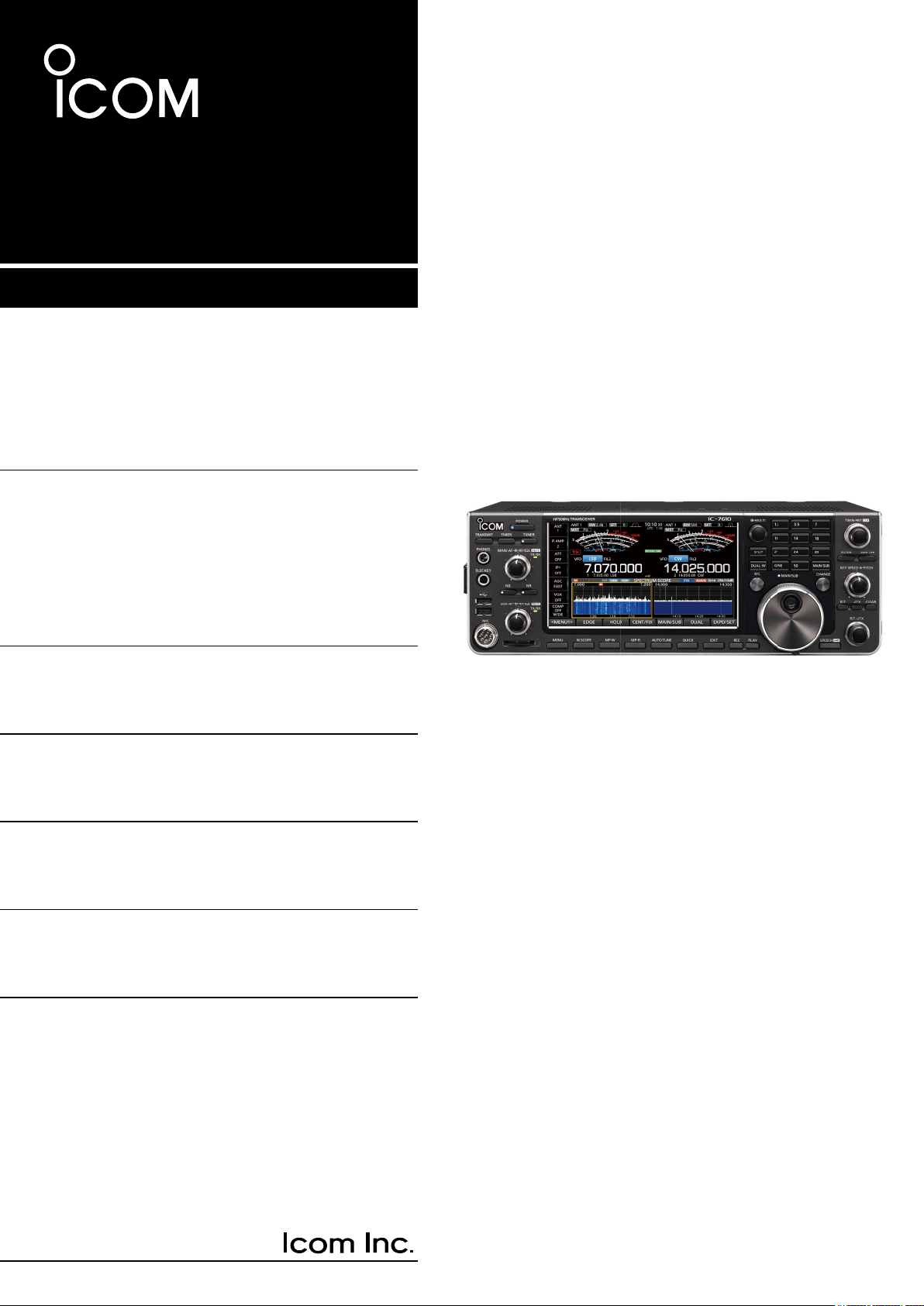
BASIC MANUAL
HF/50 MHz TRANSCEIVER
i7610
Page 2
Thank you for choosing this Icom product. The IC-7610 HF/50 MHz TRANSCEIVER is designed and built with
Icom’s state of the art technology and craftsmanship. With proper care, this product should provide you with
years of trouble-free operation. We appreciate you making the IC-7610 your transceiver of choice, and hope you
agree with Icom’s philosophy of “technology rst.” Many hours of research and development went into the design
of your IC-7610.
IMPORTANT
READ ALL INSTRUCTIONS carefully completely
before using the transceiver.
SAVE THIS INSTRUCTION MANUAL— This instruction
manual contains basic operating instructions for the IC-
7610. For the advanced operating instructions, see the
Advanced Manual on the supplied CD.
FEATURES
• RF Direct Sampling System
The IC-7610 employs an RF direct sampling system.
RF signals are directly converted to digital data and
processed in the FPGA. This system is a leading
technology marking an epoch in amateur radio.
• 2 identical receivers
The IC-7610 has 2 independent receiver circuits for the
Main and Sub bands.
• A built-in DIGI-SEL unit
Both the Main and Sub receivers have built-in DIGI-SEL
(digital preselector) units. These reject interfering signals.
• Real-Time Spectrum Scope
Displays the Main and Sub band conditions. It provides
class-leading performance in resolution, sweep speed and
provides a 100 dB dynamic range.
• A built-in automatic antenna tuner
• Multi-function control for easy settings
• Extra large 7 inch touch screen color display
• External monitor connection with a DVI-D port
• BNC type RX IN/OUT connectors
• Class Leading RMDR and Phase Noise
Characteristics
• IP remote control capability with the optional
RS-BA1
• Remote encoder capability with the optional
RC-28 remote encoder
• Dualwatch operation
ip remote control software
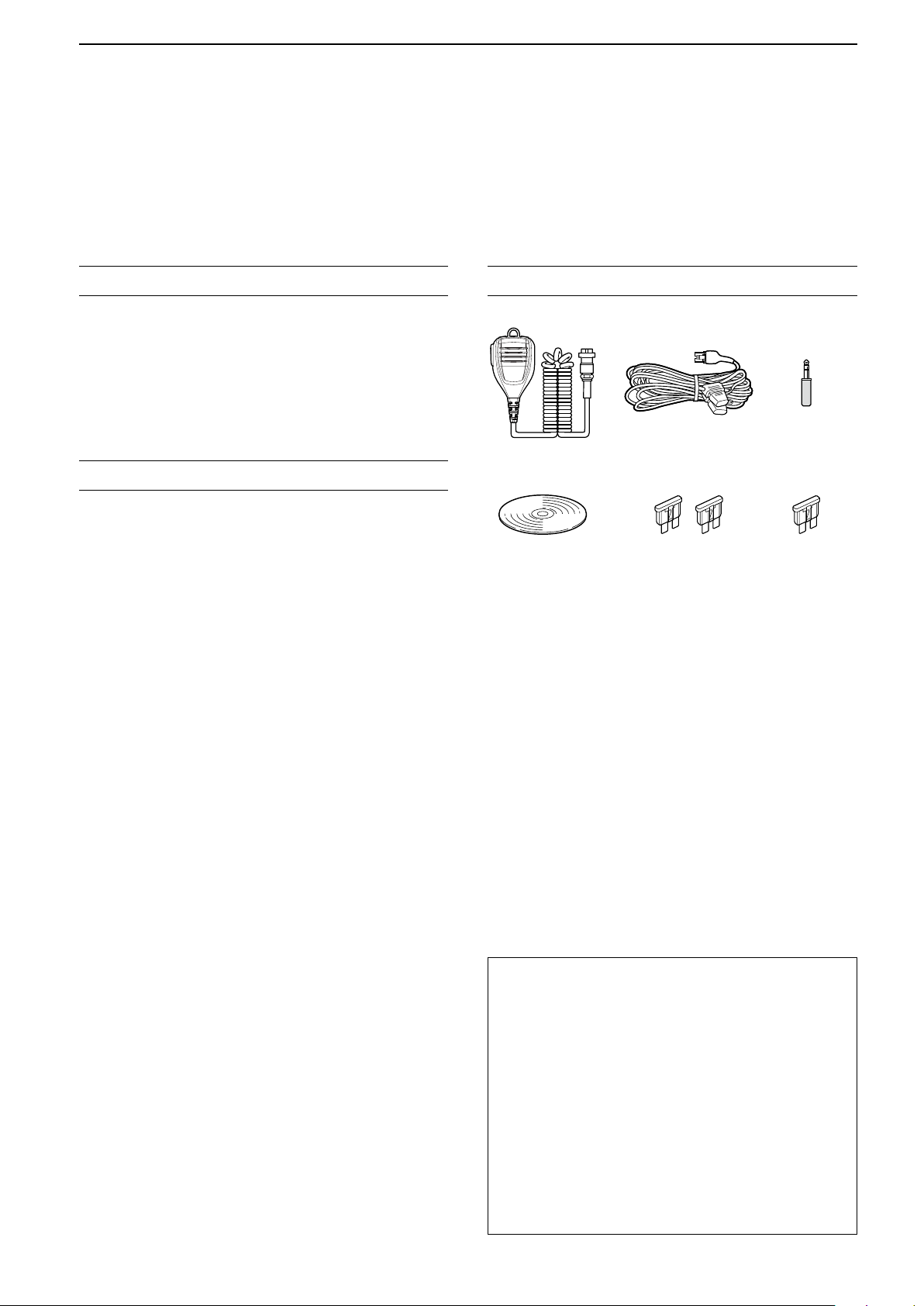
SUPPLIED ACCESSORIES
DC power cable
Hand microphone
(HM-219)
CD
L Different types of accessories may be supplied, or may
not be supplied depending on the transceiver version.
(3 m: 9.8 ft)
Spare fuse
(30 A)
This product includes RTOS “RTX” software, and is
licensed according to the software license.
This product includes “zlib” open source software,
and is licensed according to the open source
software license.
CW key plug
(6.35 mm: 1/4" Stereo)
Spare fuse
(5 A)
Icom is not responsible for the destruction, damage to, or
performance of any Icom or non-Icom equipment, if the
malfunction is because of:
• Force majeure, including, but not limited to, res,
earthquakes, storms, oods, lightning, or other natural
disasters, disturbances, riots, war, or radioactive
contamination.
• The use of Icom transceivers with any equipment that is
not manufactured or approved by Icom.
This product includes “libpng” open source software,
and is licensed according to the open source
software license.
Refer to the Text les in the License folder of
included CD for information on the open source
software being used by this product.
i
Page 3
FCC INFORMATION
TRADEMARKS
This equipment has been tested and found to comply
with the limits for a Class B digital device, pursuant
to part 15 of the FCC Rules. These limits are
designed to provide reasonable protection against
harmful interference in a residential installation. This
equipment generates, uses and can radiate radio
frequency energy and, if not installed and used in
accordance with the instructions, may cause harmful
interference to radio communications. However, there
is no guarantee that interference will not occur in a
particular installation. If this equipment does cause
harmful interference to radio or television reception,
which can be determined by turning the equipment
off and on, the user is encouraged to try to correct
the interference by one or more of the following
measures:
• Reorient or relocate the receiving antenna.
• Increase the separation between the equipment
and receiver.
• Connect the equipment into an outlet on a
circuit different from that to which the receiver is
connected.
• Consult the dealer or an experienced radio/TV
technician for help.
WARNING: MODIFICATION OF THIS DEVICE
TO RECEIVE CELLULAR RADIOTELEPHONE
SERVICE SIGNALS IS PROHIBITED UNDER FCC
RULES AND FEDERAL LAW.
Icom, Icom Inc. and the Icom logo are registered trademarks
of Icom Incorporated (Japan) in Japan, the United States,
the United Kingdom, Germany, France, Spain, Russia,
Australia, New Zealand and/or other countries.
Microsoft, Windows and Windows Vista are registered
trademarks of Microsoft Corporation in the United States
and/or other countries.
Adobe, Acrobat, and Reader are either registered
trademarks or trademarks of Adobe Systems Incorporated
in the United States and/or other countries.
All other products or brands are registered trademarks or
trademarks of their respective holders.
EXPLICIT DEFINITIONS
WORD DEFINITION
R DANGER!
R WARNING!
CAUTION
NOTE
Personal death, serious injury or an
explosion may occur.
Personal injury, fire hazard or electric
shock may occur.
Equipment damage may occur.
Recommended for optimum use. No
risk of personal injury, fire or electric
shock.
ABOUT SPURIOUS SIGNALS
CAUTION: Changes or modications to this device,
not expressly approved by Icom Inc., could void
your authority to operate this device under FCC
regulations.
ABOUT CE AND DOC
Hereby, Icom Inc. declares that the
versions of IC-7610 which have the
“CE” symbol on the product, comply
with the essential requirements of the
Radio Equipment Directive, 2014/53/EU, and the
restriction of the use of certain hazardous substances
in electrical and electronic equipment Directive,
2011/65/EU. The full text of the EU declaration
of conformity is available at the following internet
address:
http://www.icom.co.jp/world/support
Spurious signals may be received near the following
frequencies. These are made in the internal circuit and
does not indicate a transceiver malfunction:
• 28.671 MHz • 50.516 MHz • 51.881 MHz
• 53.246 MHz • 53.760 MHz
DISPOSAL
The crossed-out wheeled-bin symbol
on your product, literature, or
packaging reminds you that in the
European Union, all electrical and
electronic products, batteries, and
accumulators (rechargeable batteries)
must be taken to designated collection locations at
the end of their working life. Do not dispose of these
products as unsorted municipal waste.
Dispose of them according to the laws in your area.
ii
Page 4
ABOUT THE TOUCH SCREEN
D Touch operation
In the Full manual or Basic manual, the touch
operation is described as shown below.
Touch
If the display is touched briey, one short beep
sounds.
Touch for 1 second
If the display is touched for 1 second, one
short and one long beep sound.
ABOUT THE SUPPLIED CD
The following items are included on the CD.
• Basic manual (English)
Instructions for basic operations, the same as this
manual.
• Advanced manual (English)
Instructions for advanced operations in English.
D Touch screen precautions
• The touch screen may not properly work when the
LCD protection lm or sheet is attached.
• Touching the screen with your nger nails, sharp
topped object and so on, or touching the screen
hard may damage it.
• Tablet PC’s operations such as ick, pinch in and
pinch out cannot be performed on this touch screen.
D Touch screen maintenance
• If the touch screen becomes dusty or dirty, wipe it
clean with a soft, dry cloth.
• When you wipe the touch screen, be careful not to
push it too hard or scratch it with your nger nails.
Otherwise you may damage the screen.
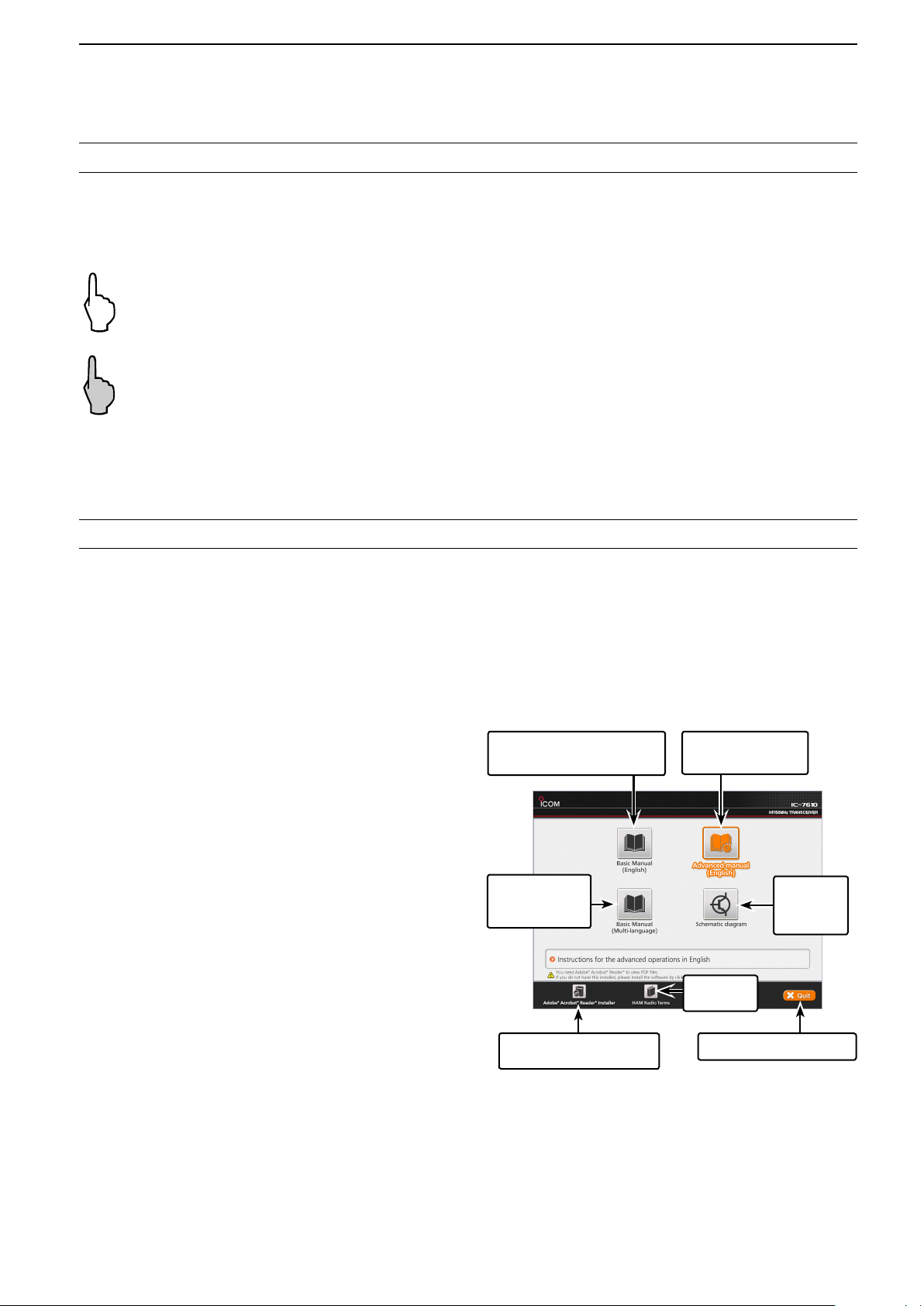
Starting the CD
1. Insert the CD into the CD drive.
2. Double click “Menu.exe” on the CD.
• Depending on the PC setting, the menu screen shown
below is automatically displayed.
3. Click the desired button to open the file.
L To close the Menu screen, click [Quit].
• Basic manual (Multi-language)
Instructions for basic operations in multiple
languages.
• Schematic diagram
Includes the schematic and block diagrams.
• HAM radio Terms (English)
A glossary of HAM radio terms in English.
®
• Adobe
Acrobat® Reader® Installer
Installer for Adobe® Acrobat® Reader®.
To read the manuals or Schematic diagram, Adobe
®
Acrobat® Reader® is required. If you have not
installed it, please install the Adobe Acrobat Reader
on the CD or download it from Adobe Systems
Incorporated’s website.
A PC with the following Operating System is required.
• Microsoft
®
Windows® 10
• Microsoft® Windows® 8.1
• Microsoft® Windows® 7
Opens the English
Basic manual (this manual)
Opens the
multi-language
Basic manual
Opens the English
Advanced manual
Opens the
Schematic
diagram
Opens the
Glossary
Installs Adobe® Acrobat®
®
Reader
L Different types of menu screen may be displayed,
depending on the transceiver version.
Closes the Menu screen
iii
Page 5

ABOUT THE CONSTRUCTION OF THE MANUAL
There are two different types of manuals for this transceiver, the Basic manual (this manual) and the Advanced
manual.
D Basic manual (This manual)
Instructions for the basic operations, precautions, installations and connections.
D Advanced manual (PDF type)
Instructions for the advanced operations, such as listed below and more...
L The Advanced manual is on the CD that is supplied with the transceiver, or can be downloaded from the Icom website.
http://www.icom.co.jp/world/support
• User Band Edge
• IP Plus function
• Main/Sub Band Tracking function
• Adjusting the Drive Gain level
• VOX function
• ∂TX function
• Operating CW <Advanced>
• Operating RTTY (FSK) and PSK
• Data mode (AFSK) operation
• Scope operation <Advanced>
• Voice Recorder functions
• Voice TX Memory operation
• Using an SD card and USB ash drive <Advanced>
• Memory operation
• Scan
• Set mode <Advanced>
• Clock and Timers <Advanced>
• Updating the rmware
• Replacing fuse
• Cleaning
And more....
iv
Page 6

ABOUT THE INSTRUCTIONS
MENU
MENU
MENU
MENU
The Basic and Advanced manuals are described in
the following manner.
“ ” (Quotation marks):
Used to indicate icons, setting items, and screen titles
displayed on the screen.
The screen titles are also indicated in uppercase
letters. (Example: FUNCTION screen)
[ ] (brackets):
Used to indicate keys.
Routes in the set modes and setting screens
Routes in the set mode, setting screen and the setting
items are described in the following manner.
» SET > Time Set > Date/Time
Instruction example
D Setting the current date
1. Open the DATE/TIME screen.
» SET > Time Set > Date/Time
Detailed instruction
1. Push
• Opens the MENU screen.
.
2. Touch [SET].
2. Touch “Date/Time.”
3. Touch “Date.”
• Opens the date editing screen.
• Opens the SET screen.
3. Touch “Time Set.”
• Opens the TIME SET screen.
4. Touch “Date/Time.”
• Opens the DATE/TIME screen.
5. Touch “Date.”
• Opens the date editing screen.
6. Touch [+] and [-] to set the date.
7. Touch [SET] to set the date.
LTouch to cancel.
• Returns to the previous screen.
v
Page 7

TABLE OF CONTENTS
IMPORTANT ............................................................... i
FEATURES ................................................................. i
SUPPLIED ACCESSORIES ....................................... i
FCC INFORMATION ..................................................ii
TRADEMARKS ...........................................................ii
EXPLICIT DEFINITIONS ............................................ii
DISPOSAL ..................................................................ii
ABOUT CE AND DOC ................................................ ii
ABOUT THE TOUCH SCREEN ................................iii
ABOUT THE SUPPLIED CD .....................................iii
ABOUT THE CONSTRUCTION OF THE MANUAL ..iv
ABOUT THE INSTRUCTIONS .................................. v
PRECAUTIONS ....................................................... viii
1. PANEL DESCRIPTION .................................... 1-1
Front panel ....................................................... 1-1
Rear panel ........................................................ 1-3
Touch screen display ........................................ 1-4
D MENU screen ............................................. 1-6
D Multi-function menus .................................. 1-6
D Multi-function key group ............................. 1-7
D QUICK MENU ............................................ 1-7
Keyboard entering and editing ......................... 1-8
D Keyboard types .......................................... 1-8
D Entering and editing ................................... 1-8
D Entering and editing example ..................... 1-9
2. INSTALLATION AND CONNECTIONS ........... 2-1
Using the desktop stands ................................. 2-1
Selecting a location .......................................... 2-1
Heat dissipation ................................................ 2-1
Grounding ......................................................... 2-1
Connecting an external DC power supply ....... 2-1
Connecting the antenna tuner .......................... 2-2
Connecting a Transverter ................................. 2-2
Linear amplier connections ............................. 2-3
D Connecting the IC-PW1/IC-PW1EURO ..... 2-3
D Connecting a non-Icom linear amplier ...... 2-3
3. BASIC OPERATION ........................................ 3-1
When rst applying power ................................ 3-1
Turning power ON or OFF ................................ 3-1
Adjusting the volume level ................................ 3-1
Selecting the VFO and Memory modes ........... 3-1
Selecting the Main and Sub bands ................... 3-2
D Switching the Main band and Sub band ..... 3-2
Dualwatch operation ......................................... 3-2
D Using the Dualwatch operation .................. 3-2
Selecting the operating band ............................ 3-3
D
Selecting the operating band
on the keypad ............................................. 3-3
D Selecting the operating band
on the screen ............................................. 3-3
Selecting the operating mode ........................... 3-3
Setting the frequency ....................................... 3-4
D Using the Main Dial .................................... 3-4
D Setting the Tuning Step function ................3-4
D Changing the Tuning Step .......................... 3-4
D Using the 1 Hz step Fine Tuning function ..3-4
D Using the 1/4 Tuning function ..................... 3-5
D Using the Auto Tuning Step function .......... 3-5
D Directly entering a frequency ..................... 3-5
Dial Lock function ............................................. 3-6
RF gain and SQL level .....................................3-7
Meter display .................................................... 3-7
D Selecting the Meter readout ....................... 3-7
D About the Multi-function meter ................... 3-7
D Displaying the Multi-function meter ............ 3-8
Adjusting the transmit output power ................. 3-8
D Adjusting the transmit output power ........... 3-8
Adjusting the microphone gain ......................... 3-9
Basic transmission ........................................... 3-9
4. RECEIVING AND TRANSMITTING ................. 4-1
Preampliers .................................................... 4-1
Attenuator ......................................................... 4-1
RIT function ...................................................... 4-1
D Using the RIT Monitor function ................... 4-1
AGC function control ........................................ 4-2
D Selecting the AGC time constant
preset value ............................................... 4-2
D Setting the AGC time constant ...................4-2
Using the Twin PBT .......................................... 4-3
Selecting the IF lter ......................................... 4-4
Selecting the IF lter shape .............................. 4-4
Noise Blanker ................................................... 4-5
D Adjusting the NB level and time ................. 4-5
Noise Reduction ............................................... 4-5
D Adjusting the Noise Reduction level ........... 4-5
Digital Selector ................................................. 4-6
D Turning ON the Digital Selector function .... 4-6
D Adjusting the center frequency ................... 4-6
Notch Filter ....................................................... 4-6
D Selecting the Notch function type ............... 4-6
D Auto Notch function .................................... 4-6
D Manual Notch function ............................... 4-7
Monitor function ................................................ 4-7
Speech Compressor (SSB) .............................. 4-8
Auto Tuning function (AM/CW) ......................... 4-8
Split frequency operation .................................. 4-9
D Using the Quick Split function .................... 4-9
D Using the receive and transmit frequencies
set to Main and Sub ................................... 4-9
Split Lock function .......................................... 4-10
Setting the transmit lter width ....................... 4-10
vi
Page 8

TABLE OF CONTENTS (Continued)
Operating CW ................................................. 4-10
D Setting the CW pitch control ..................... 4-10
D Setting the keying speed .......................... 4-11
D Using the Break-in function ...................... 4-11
D Monitoring the CW side tone .................... 4-12
D APF (Audio Peak Filter) operation ........... 4-12
D About the Electronic Keyer function ......... 4-13
5. SCOPE OPERATION ....................................... 5-1
Spectrum scope screen .................................... 5-1
D Marker ........................................................ 5-1
D Using the Spectrum Scope ........................ 5-1
D Displaying the Mini scope screen ............... 5-2
Audio scope screen .......................................... 5-2
D Using the Audio scope ...............................5-2
D AUDIO SCOPE SET screen .......................5-3
6. SD CARD/USB FLASH DRIVE ....................... 6-1
About the SD cards .......................................... 6-1
About the USB ash drive ................................ 6-1
Saving data ...................................................... 6-1
Inserting ............................................................ 6-1
Formatting ........................................................ 6-2
D Formatting the SD card or
USB ash drive .......................................... 6-2
Unmounting ...................................................... 6-2
7. ANTENNA TUNER OPERATION .................... 7-1
About the Antenna memory settings ................7-1
D The Antenna memory screen .....................7-1
D Saving an antenna connector setting ......... 7-1
D Selecting the antenna type ......................... 7-2
About the internal antenna tuner ...................... 7-2
Using the Internal antenna tuner ...................... 7-3
D Manual tuning ............................................. 7-3
D PTT Tuner start ..........................................7-3
About an external antenna tuner ...................... 7-3
D Using the AH-4 or AH-740 .......................... 7-3
D Using an external antenna tuner ................ 7-4
Emergency mode (Tuner) .................................7-4
8. SET MODE ....................................................... 8-1
Set mode description ........................................ 8-1
D Entering the Set mode ............................... 8-1
Tone Control/TBW ........................................... 8-2
Function ............................................................ 8-2
Connectors ....................................................... 8-5
Network ............................................................ 8-7
Display .............................................................. 8-8
Time Set ...........................................................8-9
SD Card ............................................................ 8-9
USB Flash Drive ............................................. 8-10
Others ............................................................. 8-10
9. CLOCK AND TIMERS ..................................... 9-1
Setting the date and time ................................. 9-1
D Setting the date .......................................... 9-1
D Setting the current time .............................. 9-1
D Setting the UTC offset ................................ 9-1
D Displaying CLOCK2 ................................... 9-1
D Setting the CLOCK2 UTC offset ................. 9-2
D Editing the CLOCK2 name ......................... 9-2
10. MAINTENANCE ............................................. 10-1
Resetting ........................................................ 10-1
D Partial reset .............................................. 10-1
D All reset .................................................... 10-1
Troubleshooting .............................................. 10-2
11. SPECIFICATIONS ......................................... 11-1
D General .................................................... 11-1
D Transmitter ............................................... 11-1
D Receiver ................................................... 11-2
D Antenna tuner ........................................... 11-2
12. OPTIONS ....................................................... 12-1
13. CONNECTOR INFORMATION ......................13-1
Interface information ....................................... 13-1
ACC sockets ................................................... 13-2
PHONES ........................................................ 13-3
ELEC-KEY ......................................................13-3
KEY ................................................................13-3
DC 13.8 V ....................................................... 13-3
TUNER ........................................................... 13-3
MIC ................................................................. 13-3
EXT KEYPAD ................................................. 13-4
REMOTE ........................................................ 13-4
METER ........................................................... 13-4
USB port (type A) ...........................................13-4
ALC ................................................................ 13-4
SEND ............................................................. 13-4
LAN ................................................................ 13-5
EXT-DISPLAY .................................................13-5
USB 2 ............................................................. 13-5
USB 1 ............................................................. 13-5
EXT-SP A / EXT-SP B ..................................... 13-5
REF IN ............................................................ 13-5
X-VERTER .....................................................13-6
ANT 1 / ANT 2 ................................................ 13-6
RX-ANT IN/OUT ............................................. 13-6
INSTALLATION NOTES ............................................ I
INDEX........................................................................ II
vii
Page 9

PRECAUTIONS
R DANGER HIGH RF VOLTAGE! NEVER touch an
antenna or antenna connector while transmitting. This could
cause an electrical shock or burn.
R DANGER! NEVER operate the transceiver near
unshielded electrical blasting caps or in an explosive
atmosphere. This could cause an explosion and death.
R WARNING RF EXPOSURE! This device emits Radio
Frequency (RF) energy. Extreme caution should be
observed when operating this device. If you have any
questions regarding RF exposure and safety standards
please refer to the Federal Communications Commission
Ofce of Engineering and Technology’s report on
Evaluating Compliance with FCC Guidelines for Human
Radio Frequency Electromagnetic Fields (OET Bulletin 65).
R WARNING! NEVER operate the transceiver with a
headset or other audio accessories at high volume levels. If
you experience a ringing in your ears, reduce the volume or
discontinue use.
R WARNING! NEVER apply AC power to the [DC13.8V]
socket on the transceiver rear panel. This could cause a re
or damage the transceiver.
R WARNING! NEVER apply more than 16 V DC to the
[DC13.8V] socket on the transceiver rear panel. This could
cause a re or damage the transceiver.
R WARNING! NEVER reverse the DC power cable
polarity. This could cause a re or damage the transceiver.
R WARNING! NEVER remove the fuse holder on the DC
power cable. Excessive current caused by a short could
cause a re or damage the transceiver.
R WARNING! NEVER let metal, wire or other objects
contact the inside of the transceiver, or make incorrect
contact with connectors on the rear panel. This could cause
an electric shock or damage the transceiver.
R WARNING! NEVER operate or touch the transceiver
with wet hands. This could cause an electric shock or
damage to the transceiver.
R WARNING! NEVER operate the equipment if you notice
an abnormal odor, sound or smoke. Immediately turn OFF
the power and/or remove the DC power cable. Contact your
Icom dealer or distributor for advice.
R WARNING! NEVER put the transceiver on an unstable
place where the transceiver may suddenly move or fall.
This could cause an injury or damage the transceiver.
CAUTION: DO NOT expose the transceiver to rain, snow
or any liquids. They could damage the transceiver.
CAUTION: DO NOT change the internal settings of the
transceiver. This may reduce transceiver performance and/
or damage the transceiver. The transceiver warranty does
not cover any problems caused by unauthorized internal
adjustments.
CAUTION: DO NOT install the equipment in a place
without adequate ventilation, or block any cooling vents
on the top, rear, sides or bottom of the transceiver or the
cooling fan. Heat dissipation may be reduced and damage
the transceiver.
CAUTION: DO NOT use harsh solvents such as benzine or
alcohol when cleaning. This could damage the equipment
surfaces. If the surface becomes dusty or dirty, wipe it clean
with a soft, dry cloth.
CAUTION: DO NOT place or leave the transceiver in
areas with temperatures below 0°C (32°F) or above 50°C
(122°F).
CAUTION: DO NOT place the transceiver in excessively
dusty environments, or in direct sunlight. This could
damage the transceiver.
CAUTION: DO NOT set the transceiver’s RF output power
to more than a connected linear amplier’s maximum input
level. Otherwise, the linear amplier will be damaged.
CAUTION: DO NOT use non-Icom microphones. Other
microphones have different pin assignments and may
damage the transceiver.
BE CAREFUL! The transceiver will become hot when
operating the transceiver continuously for long periods of
time.
NEVER leave the transceiver in an insecure place to avoid
use by unauthorized persons.
Turn OFF the transceiver’s power and disconnect the DC
power cable when you will not use the transceiver for long
period of time.
The LCD display may have cosmetic imperfections
that appear as small dark or light spots. This is not a
malfunction or defect, but a normal characteristic of LCD
displays.
R WARNING! NEVER operate the transceiver during a
lightning storm. It may result in an electric shock, cause
a re or damage the transceiver. Always disconnect the
power source and antenna before a storm.
viii
Page 10
1
POWER
TRANSMIT
TIMER
AF RF/SQL
AF RF/SQL
NR
NB
TUNER
MENU
M.SCOPE
MP-W
MP-R
AUTO TUNE
QUICK
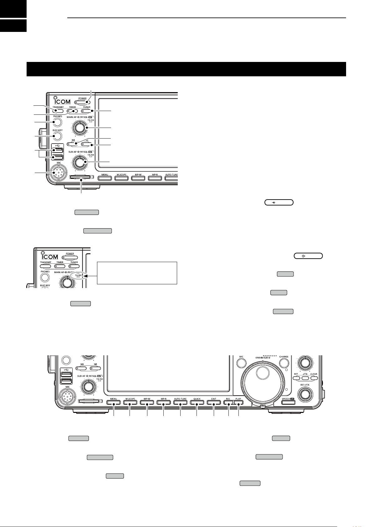
PANEL DESCRIPTION
Front panel
q
w
e
r
t
y
u
i
q POWER KEY
Turns the transceiver ON or OFF.
w TRANSMIT KEY
Toggles between transmit and receive.
!2
o
!1
!0
o
(p. 3-1)
(p. 3-9)
The TX/RX indicator
• Lights green while receiving.
• Lights red while transmitting.
r HEADPHONE JACK [PHONES] (p. 13-3)
Connects to standard stereo headphones.
t ELECTRONIC KEYER JACK [ELEC-KEY] (p. 13-3)
Connects to a paddle to use the internal electronic
keyer for the CW operations.
y USB PORT [USB A] (p. 13-4)
Insert a USB ash drive, USB A type keyboard,
RC-28
u MICROPHONE CONNECTOR [MIC] (p. 13-3)
Connects to the supplied or an optional microphone.
i SD CARD SLOT [SD CARD] (p. 6-1)
Accepts an SD card. The indicator next to the slot
lights blue when inserted.
o VOLUME CONTROL
L The upper control is for the Main band, and the
• Push to turn the Mute function ON or OFF.
- The TX/RX indicator lights orange when the Mute
• Adjusts the audio output level.
RF GAIN/SQUELCH CONTROL
Adjusts the RF gain and squelch threshold levels.
!0 NOISE REDUCTION KEY
Turns the Noise Reduction function ON or OFF.
remote encoder, mouse or hub.
(p. 3-1)
lower control is for the Sub band.
function is ON.
(p. 3-7)
(p. 4-5)
e TIMER KEY
Turns the Sleep Timer or Daily Timer function ON or
OFF.
!3 !4
!3 MENU KEY
Displays the MENU screen.
!4 MINI SCOPE KEY
Displays the Mini Scope or Spectrum Scope.
!5 MEMO PAD WRITE KEY
Saves the displayed contents into the Memo Pad.
(p. 8-1)
(p. 5-2)
!5 !6 !7 !8 !9 @0 @1
!1 NOISE BLANKER KEY
Turns the Noise Blanker ON or OFF.
!2 ANTENNA TUNER KEY
Turns the antenna tuner ON or OFF, or activates
the tuner.
!6 MEMO PAD READ KEY
Sequentially calls up the contents in the Memo Pad.
!7 AUTO TUNE KEY
Automatically tunes the operating frequency to a
received CW signal.
!8 QUICK KEY
Displays the QUICK MENU.
(p. 1-7)
(p. 4-5)
(p. 7-3)
(p. 4-8)
1-1
Page 11
MULTI
SPLIT
DUAL-W
GENE
XFC
MAIN DIAL
MAIN DIAL
Front panel (Continued)
SPEECH
MAIN DIAL
CHANGE
RIT/
TX
TX
CLEAR
RIT
MAIN/SUB
APF/TPF
FILTER
TWIN PBT
CLR
1.8
50
EXIT
REC
PLAY
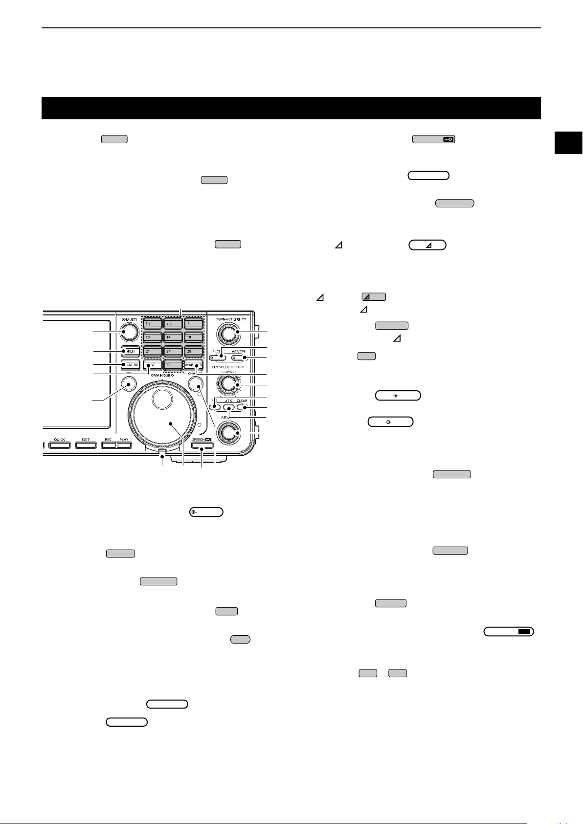
PANEL DESCRIPTION
1
!9 EXIT KEY
Exits a setting screen or returns to the previous
screen.
@0 VOICE MEMORY RECORD KEY
Saves the previously received signal for the preset
time period set in REC Time, using the Instant
Replay function, or starts recording a QSO audio
onto an SD card.
@1 VOICE MEMORY PLAY BACK KEY
Plays back the last 5 seconds of the Instant Replay
memory, or all of the Instant Replay memory.
$0
@2
@3
@4
@5
@6
@7 @8 @9
@2 MULTI-FUNCTION CONTROL
Displays the Multi-function menu for various
adjustments, or selects an item.
@3 SPLIT KEY
Turns the Split function ON or OFF.
@4 DUALWATCH KEY
Turns the Dualwatch function ON or OFF.
@5 GENERAL COVERAGE BAND KEY
Selects the general coverage band.
@6 TRANSMIT FREQUENCY CHECK KEY
(p. 4-1, 4-9, 4-10)
Enables you to monitor the transmit frequency while
holding it down in the Split mode.
@7 TENSION ADJUSTER
Adjusts the friction of
@8 MAIN DIAL
Changes the operating frequency.
(p. 4-9)
(p. 3-2)
(p. 3-4)
#0
(p. 1-6)
.
#9
#8
#7
#6
#5
#4
#3
#2
#1
@9 SPEECH/LOCK KEY
• Announces the operating frequency and mode by
pushing this key.
• Electronically locks
this key for 1 second.
#0 MAIN/SUB CHANGE KEY
Toggles the frequency, mode and selected memory
channel between the Main and Sub band.
#1 RIT/
Shifts the receive or transmit frequency up to
#2
Turns the TX function ON or OFF.
#3 CLEAR KEY
Clears the RIT or TX shift frequency.
#4 RIT KEY
Turns the Receiver Incremental Tuning (RIT)
#5 KEY SPEED
Adjusts the internal electronic CW keyer speed.
CW PITCH
Shifts the received CW audio pitch and the CW
#6 MAIN/SUB ACCESS KEY
Selects the Main or Sub band frequency readout.
#7 AUDIO PEAK FILTER/
In the CW mode, turns the Audio Peak Filter ON or
#8 FILTER KEY
Selects one of three IF lters.
#9
Adjusts the IF lter’s passband width.
$0 KEYPAD
Selects the operating band by pushing once, or call
TX CONTROL
±9.99 kHz without changing the transmit or receive
frequency.
TX KEY
(p. 4-1)
function ON or OFF.
KEY
PITCH
SPEED
KEY
PITCH
SPEED
side tone pitch without changing the operating
frequency.
• The selected band’s frequency is displayed clearly
whereas the non-selected band’s frequency is
displayed in gray.
TWIN PEAK FILTER KEY
OFF, and in the RTTY mode, turns the Twin Peak
Filter ON or OFF.
TWIN PASSBAND TUNING CONTROL
(p. 4-3)
~
up other stacked frequencies by pushing the same
key several times.
CONTROL (p. 4-10)
(p. 4-4)
by holding down
(p. 3-2)
(p. 4-1)
CONTROL (p. 4-11)
(p. 3-2)
(p. 4-12)
1
2
3
4
5
6
7
8
9
10
11
12
13
14
15
16
17
18
19
20
21
1-2
Page 12
1
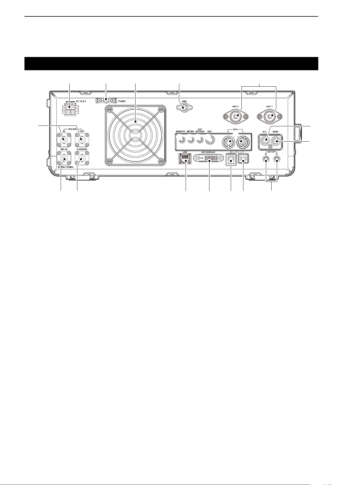
PANEL DESCRIPTION
Rear panel
q ew r
!5
!3 !2 !1 o i
!4
q DC POWER SOCKET [DC 13.8 V]
Connects to 13.8 V DC through the DC power
cable.
w TUNER CONTROL SOCKET [TUNER]
Accepts the control cable from an optional
AH-4 or AH-740
e COOLING FAN
Cools the PA unit when necessary.
r GROUND TERMINAL [GND]
Connects to ground to prevent electrical shocks,
TVI, BCI and other problems.
t ANTENNA CONNECTOR [ANT1]/[ANT2]
Connects to a 50 Ω antenna. If you use the AH-4 or
AH-740, you must connect the antenna to [ANT1].
y ALC INPUT JACK [ALC]
Connects to the ALC output jack of a non-Icom
linear amplier.
u SEND CONTROL JACK [SEND]
Connects to control transmit with non-Icom external
units.
i EXTERNAL SPEAKER JACK A/B [EXT-SP]
Accepts a 4 ~ 8 Ω external speaker.
o USB PORT [USB 1] (Type B)
Connects to a PC for remote control operations.
!0 USB PORT [USB 2] (Type B)
For digital data input or output.
!1 EXTERNAL DISPLAY CONNECTOR
[EXT-DISPLAY]
Connects to an external display monitor.
automatic antenna tuner.
t
y
!7 !8 !9!6
!2 ETHERNET CONNECTOR [LAN]
Connects to a PC network through a LAN.
!3 TRANSVERTER CONNECTOR [X-VERTER]
Connects to an external transverter for input/output.
!4 REFERENCE SIGNAL INPUT [REF IN]
Input for a 10 MHz reference signal through the
BNC connector.
!5 RECEIVE ANTENA [RX ANT–IN]/[RX ANT–OUT]
Connects to an external unit, such as preamplier
or RF lter, using BNC connectors.
• This is located between the transmit/receive switching
circuit and receiver’s RF stage.
!6 CI-V REMOTE CONTROL JACK [REMOTE]
Connects to a PC or other transceiver for remote
control.
!7 METER JACK [METER]
Outputs received signal strength, transmit output
power, VSWR, ALC, speech compression, V
levels for an external meter.
!8 EXTERNAL KEYPAD JACK [EXT KEYPAD]
(p. 13- 4)
Connects to an external keypad for direct voice
memory, memory keyer, RTTY memory or PSK
memory transmission.
!9 STRAIGHT KEY JACK [KEY]
Connects to a straight key or external electronic keyer
with 1/4 inch standard
@0 ACC SOCKET [ACC1]/[ACC2]
Connects to devices to control an external unit or to
control the transceiver.
@0
u
!0
d or Id
plug.
1-3
Page 13
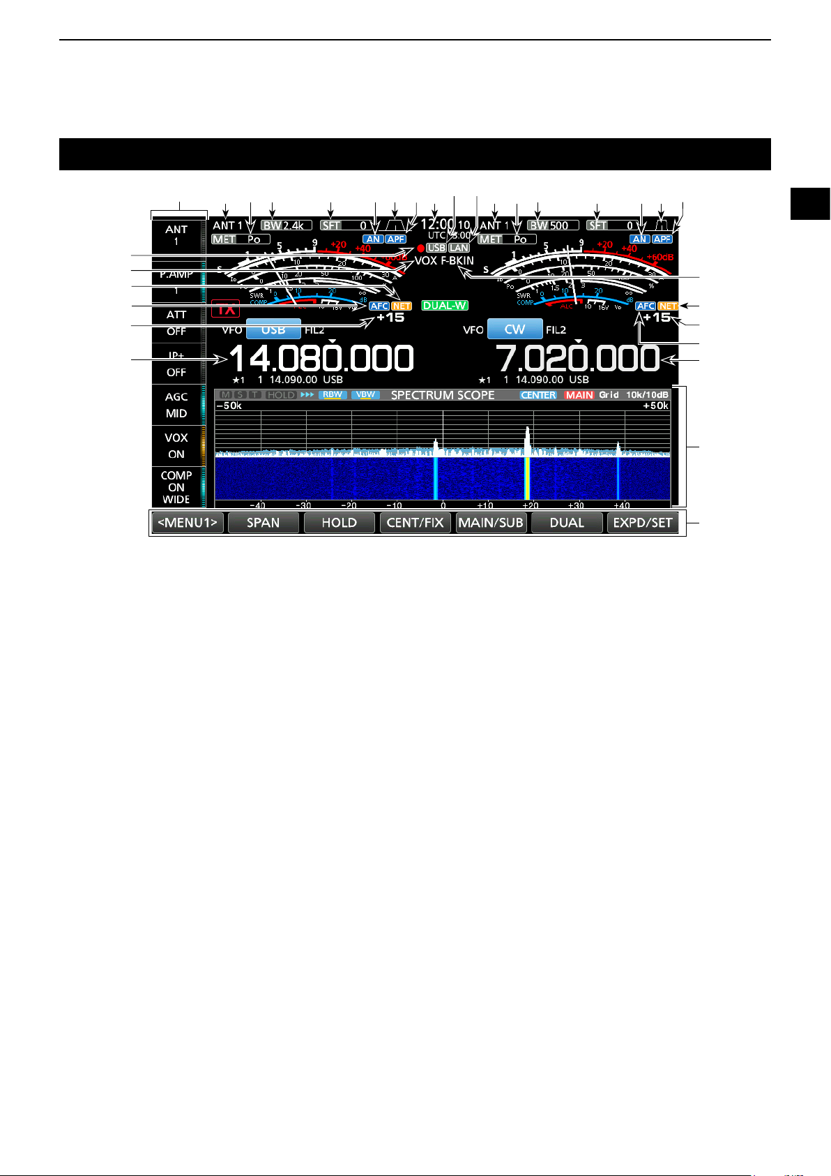
Touch screen display
PANEL DESCRIPTION
1
w r t oyeq i w r t uye
@0
!9
!3
!5
!4
!6
q MULTI-FUNCTION KEY GROUP
Displays the Multi-function keys.
w ANTENNA INDICATOR (p. 7-1)
Displays the selected antenna connector between
ANT 1 and ANT 2.
e METER TYPE INDICATOR (p. 3-7)
Displays the selected transmit parameter type.
Select between Po, SWR, ALC, COMP, V
r BANDWIDTH INDICATOR (p. 4-3, 4-4)
Displays the passband width of the IF lter.
t SHIFT FREQUENCY INDICATOR (p. 4-3)
Displays the shift frequency of the IF lter.
y NOTCH INDICATOR (p. 4-6)
“AN” is displayed when the Auto Notch function is
ON, and “MN” is displayed when the Manual Notch
function is ON.
u PASSBAND WIDTH INDICATOR (p. 4-3)
Displays the passband width for twin PBT operation
and the center frequency for IF shift operation.
i AUDIO PEAK FILTER (APF) INDICATOR (p. 4-12)
Displayed when the Audio Peak Filter is ON.
o CLOCK READOUT (p. 9-1)
Displays the time (2 types) set on the TIME SET
screen.
!0 USB INDICATOR (p. 6-1)
Displayed while a USB ashed drive is inserted.
!1 LAN INDICATOR
Displayed while the transceiver and the optional
RS-BA1 are connected through the LAN for remote
control operation.
d and Id.
!1!0u
!2 BK-IN/F-BKIN INDICATOR (p. 4-11)
Displayed while the Semi Break-in or Full Break-in
function is ON.
!3 NET FUNCTION INDICATOR (p. 8-7)
Displayed when the NET function is ON while in the
PSK mode.
!4 FREQUENCY OFFSET READOUT
Displays the offset value between the PSK signal
and the operating frequency, while a PSK signal is
received.
!5 AFC FUNCTION INDICATOR
Displayed while the Automatic Frequency Control
(AFC) function is ON, in the PSK mode.
!6 FREQUENCY READOUT (p. 3-4)
Displays the operating frequency.
L The non-selected band’s frequency readout (Main or
Sub) is displayed in gray.
!7 FUNCTION DISPLAY
Displayed when an item that has a function display
is selected. For example, the Spectrum Scope.
!8 FUNCTION KEYS (p. 5-1)
Displays the operating parameters, modes,
frequencies and indicators, and so on.
!9 VOX INDICATOR
Displayed while the VOX function is ON.
@0 VOICE RECORDER ICON
• “●” is displayed while recording.
• “” is displayed while pausing.
1-4
i
!2
!3
!4
!5
!6
!7
!8
1
2
3
4
5
6
7
8
9
10
11
12
13
14
15
16
17
18
19
20
21
Page 14
1
AF RF/SQL
PANEL DESCRIPTION
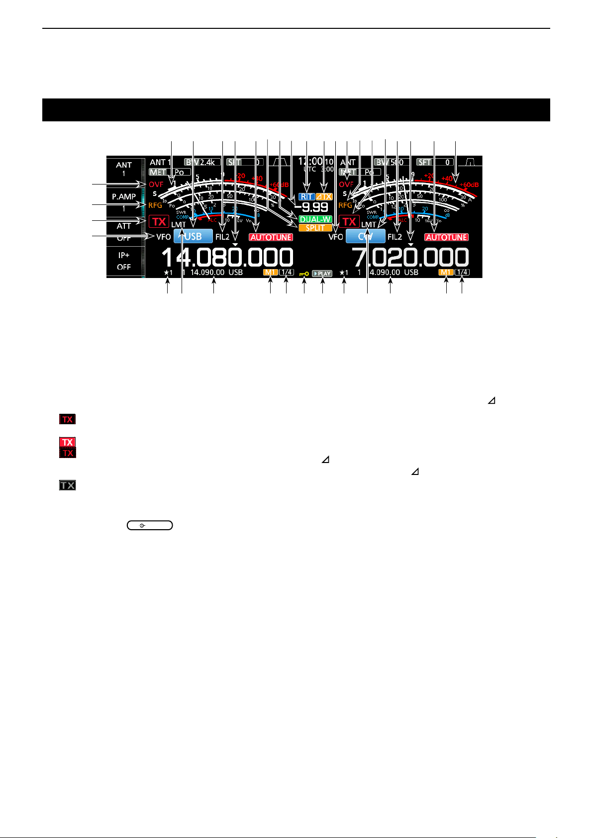
Touch screen display (Continued)
@6 @7 @7@9 @9@8 @8
#0 #1 @2@3#2 @6
@4
@3
@2
@1
@1 VFO/MEMORY ICON (p. 3-1)
“VFO” is displayed when the VFO mode is selected,
and the memory number is displayed when a
Memory channel is selected.
@2 TX STATUS INDICATOR (p. 3-4, 3-9)
Displays the transmit status of the displayed
frequency.
• is displayed while the displayed frequency is within
the amateur band range.
•
(Red background) is displayed while transmitting.
•
(With a border of short dashes) is displayed when
the selected frequency is outside of the amateur band
frequency.
• (Grayed out) is displayed while the transmitter is
inhibited.
@3 RF GAIN INDICATOR (p. 3-7)
Displayed when
(outer) is set
counterclockwise from the 11 o’clock position. The
indicator shows that the RF gain is reduced.
@4 OVF ICON (p. 3-7)
“OVF” is displayed when an excessively strong
signal is received.
@5 METER INDICATOR (p. 3-7)
Displays the S, I
d, Po, SWR, COMP, ALC and Vd
meters.
@6 MODE INDICATOR (p. 3-3)
Displays the selected operating mode.
@7 IF FILTER INDICATOR (p. 4-3, 4-4)
Displays the selected IF lter.
@8 QUICK TUNING ICON (p. 3-4)
Displayed when the quick Tuning Step function is
ON.
@9 AUTO TUNE INDICATOR (p. 4-8)
Displays “AUTOTUNE” when the Auto Tuning
function is ON.
#3 #4 @1@5 @4 @5
#5#5 #6#7$0$1#7 #9 #8#8#9 #6
#0 SPLIT ICON (p. 4-9)
Displayed when the Split function is ON.
#1 DUALWATCH ICON (p. 3-2)
Displayed when using Dualwatch.
#2 SHIFT FREQUENCY READOUT (p. 4-1)
Displays the shift offset for the RIT or
TX
functions, while these functions are ON.
#3 RIT ICON (p. 4-1)
Displayed when the RIT function is ON.
TX ICON
#4
Displayed when the TX function is ON.
#5 1/4 TUNING STEP INDICATOR (p. 3-5)
Displayed while the 1/4 Tuning Step function is ON.
#6 M1~M8/T1~T8
• Displays “M1”~“M8” while using the Memory Keyer
function is used.
• Displays “T1”~“T8” while using the Voice TX memory
function.
#7 MEMORY CHANNEL/VFO READOUT (p. 3-1)
Displays the selected memory channel contents in
the VFO mode, and displays the VFO contents in
the Memory mode.
#8 LMT ICON
Displayed if the power amplier temperature
becomes extremely high and the protection function
is activated after transmitting continuously for long
periods of time.
#9 SELECT MEMORY CHANNEL ICON
Indicates that the displayed memory channel is
assigned as a Select memory channel (★1~★3).
$0 PLAY ICON
Displayed while playing the recorded voice audio.
$1 DIAL LOCK INDICATOR (p. 3-6)
Displayed while the Lock function is ON.
1-5
Page 15
Touch screen display (Continued)
MENU
MULTI
MULTI
NB
NR
PANEL DESCRIPTION
1
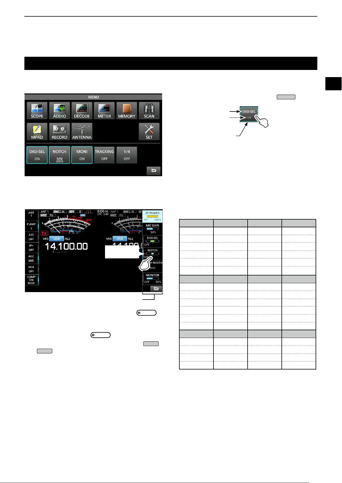
D MENU screen
D Multi-function menus
Touch to turn
ON or OFF
Multi-function menu
z Open the Multi-function menu by pushing
(Multi-function control).
z While the Multi-function menu is open, touch the
desired item and rotate
L You can open other menus by holding down
or
“BK-IN” or “COMP” in the Multi-function key group
for 1 second.
for 1 second, or touching “ATT,” “VOX,”
to adjust the value.
1
z Open the MENU screen by pushing
Function name
Status
.
2
3
4
Lights blue or orange
when in use
L The items displayed on the menu differ, depending
on the selected operating mode.
5
6
7
8
9
Multi-function menu items
10
SSB CW RTTY PSK
RF POWER RF POWER RF POWER RF POWER
MIC GAIN
DIGI-SEL DIGI-SEL DIGI-SEL DIGI-SEL
NOTCH NOTCH NOTCH NOTCH
NOTCH WIDTH NOTCH WIDTH NOTCH WIDTH NOTCH WIDTH
MONITOR MONITOR MONITOR
AM FM NB NR
RF POWER RF POWER LEVEL LEVEL
MIC GAIN MIC GAIN DEPTH
DIGI-SEL DIGI-SEL WIDTH
NOTCH NOTCH
NOTCH WIDTH
MONITOR MONITOR
ATT VOX BK-IN COMP
LEVEL GAIN DELAY LEVEL
ANTI VOX TBW
DELAY
VOICE DELAY
11
12
13
14
15
16
17
18
19
20
21
1-6
Page 16
1
QUICK
PANEL DESCRIPTION
Touch screen display (Continued)
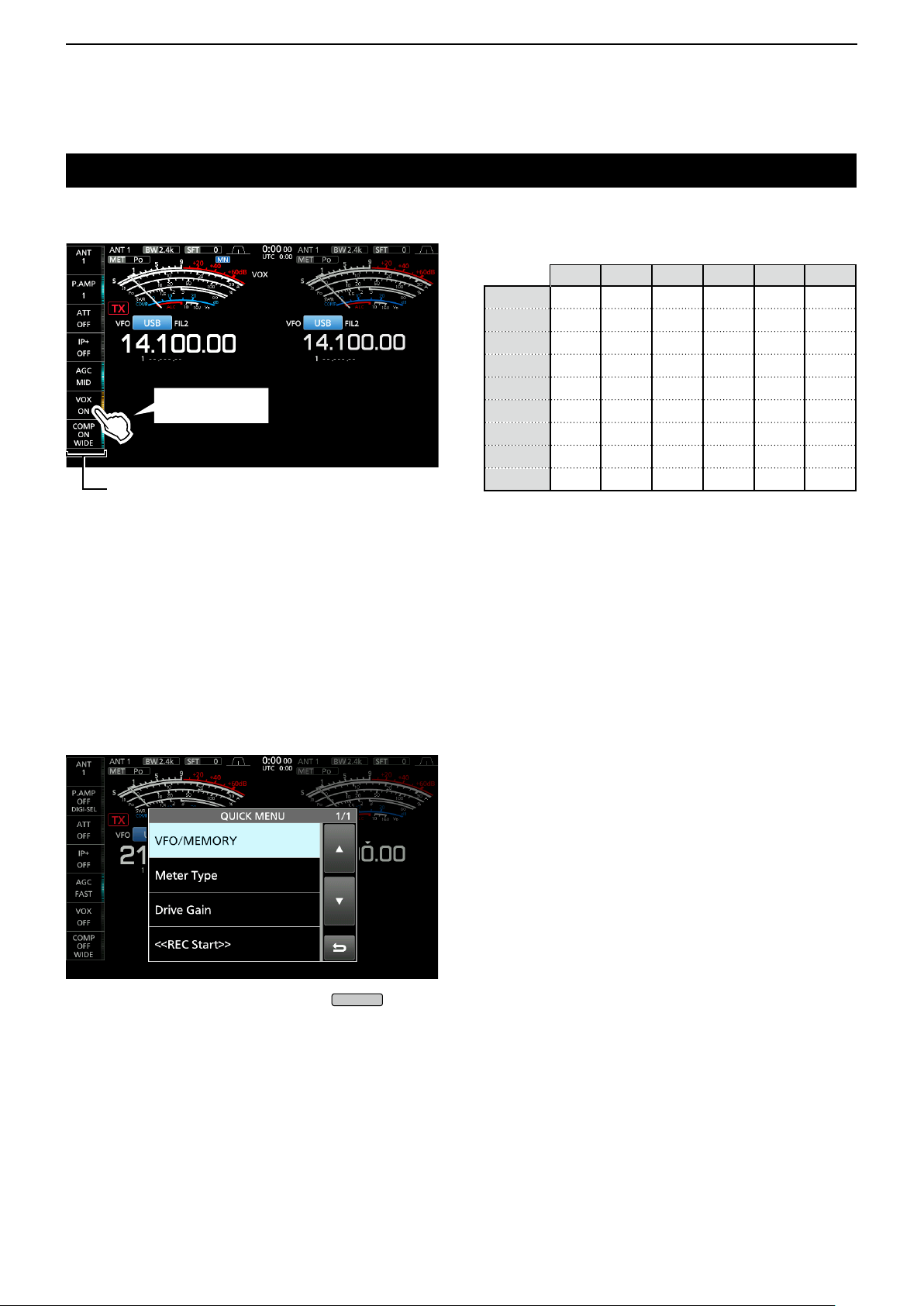
D Multi-function key group
Touch to turn ON
or OFF, or to set
Multi-function key group
Multi-function key group items
SSB CW RTTY PSK AM FM
ANT
P.AMP
ATT
IP+
AGC
VOX
BK-IN
COMP
TONE
✓ ✓ ✓ ✓ ✓ ✓
✓ ✓ ✓ ✓ ✓ ✓
✓ ✓ ✓ ✓ ✓ ✓
✓ ✓ ✓ ✓ ✓ ✓
✓ ✓ ✓ ✓ ✓ ✓
✓ ✓ ✓
✓
✓
✓
z Touch a key to turn the function ON or OFF.
z Touching “ATT,” “VOX,” “BK-IN” or “COMP” for 1
second opens the ATT menu, VOX menu, BK-IN
menu or COMP menu.
L See “Multi-function menus” on the previous page for
details.
D QUICK MENU
z Open the QUICK MENU by pushing
.
1-7
Page 17
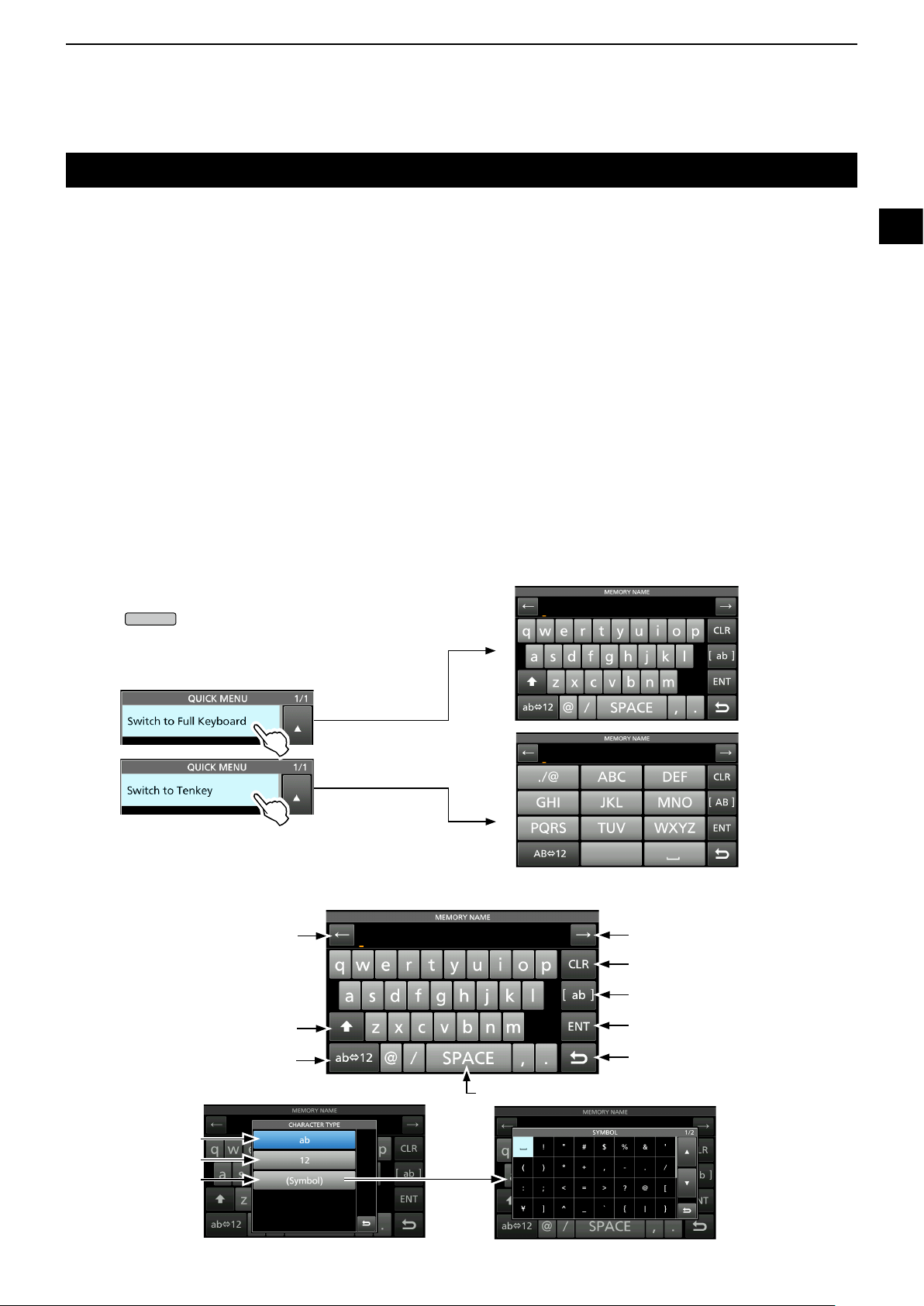
Keyboard entering and editing
QUICK
PANEL DESCRIPTION
1
You can enter and edit the items on the following screens.
LUsable characters, symbols, and the amount of characters that can be entered differs, depending on the editing item.
• MY CALL
• FILE NAME
• NETWORK NAME
• NETWORK RADIO NAME
• NETWORK USER1 ID
• NETWORK USER2 ID
• NETWORK USER 1 PASSWORD
• NETWORK USER 2 PASSWORD
• NTP SERVER ADDRESS
• CLOCK2 NAME
• KEYER MEMORY
• PSK MEMORY
• RTTY MEMORY
• VOICE TX RECORD (T1) ~ (T8)
• MEMORY NAME
D Keyboard types
You can select the Full Keyboard or Tenkey by
pushing
screen.
while displaying an entry mode
1
2
3
4
5
6
7
8
9
10
11
12
D Entering and editing
Moves the cursor backward
Enters an uppercase letter
Selects alphabet mode
or number mode
Alphabet mode
Number mode
Symbol mode
Enters a space
Moves the cursor forward
Clears the entered character
Selects the character type
Saves the entry
Cancels entry and returns to the
previous screen
13
14
15
16
17
18
19
20
21
1-8
Page 18
1
MENU
PANEL DESCRIPTION
Keypad entering and editing (Continued)
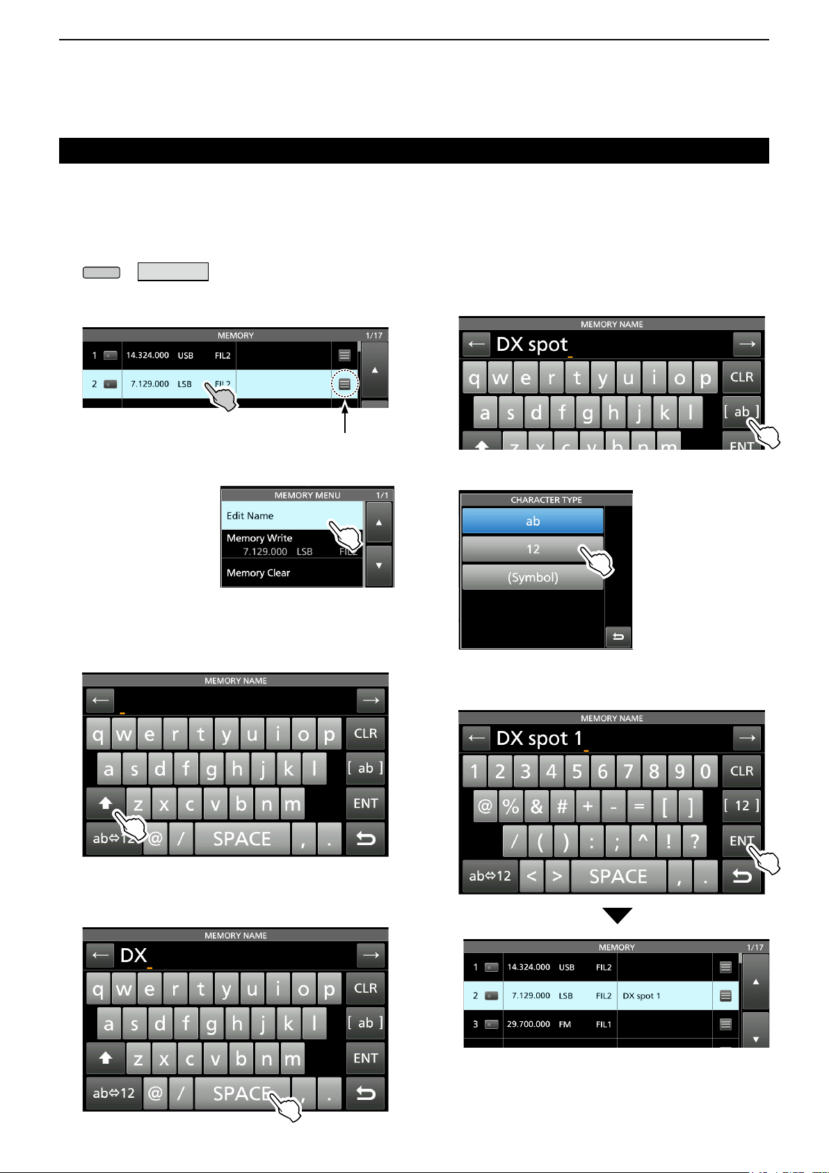
D Entering and editing example
Entering “DX spot 1” in the Memory channel 2
1. Display the MEMORY screen.
» MEMORY
2. Touch the memory channel 2 for 1 second.
• The MEMORY MENU screen is displayed.
You can also display the MEMORY
MENU screen by touching this key.
3. Touch “Edit Name.”
• The MEMORY
NAME screen is
displayed.
4. Touch [ ], and then touch [D].
L Touching [ ] changes between uppercase and
lowercase letter.
7. Touch [s], [p], [o], and then [t].
8. Touch [SPACE] to enter a space.
9. Touch [ab].
• The CHARACTER TYPE screen is displayed.
10. Touch [12].
11. Touc h [1] .
12. Touch [ENT] to save the entry.
5. Touch [ ] again, and then touch [X].
6. Touch [SPACE] to enter a space.
• Returns to the previous screen.
1-9
Page 19
INSTALLATION AND CONNECTIONS
2
Using the desktop stands
The transceiver has legs for desktop use.
z Pull-out the legs on both sides until they lock in
place.
NOTE: DO NOT hold the stand, dials and controls
when you carry the transceiver. This may damage
them.
Selecting a location
Select a location for the transceiver that allows
adequate air circulation, free from extreme heat, cold
or vibrations, and other electromagnetic sources.
Never place the transceiver in areas such as:
• Temperatures below 0°C (+32°F) or above +50°C
(+122°F).
• An unstable place that slopes or vibrates.
• In direct sunlight.
• High humidity and temperature environments.
• Dusty environments.
• Noisy environments.
Heat dissipation
• NEVER install the transceiver in a place without
adequate ventilation. Heat dissipation may be
reduced, and the transceiver may be damaged.
• DO NOT place the transceiver against walls or put
anything on top of the transceiver. This may block
airow and overheat the transceiver.
• DO NOT touch the rear panel after transmitting
continuously for long periods of time. The panel may
become hot.
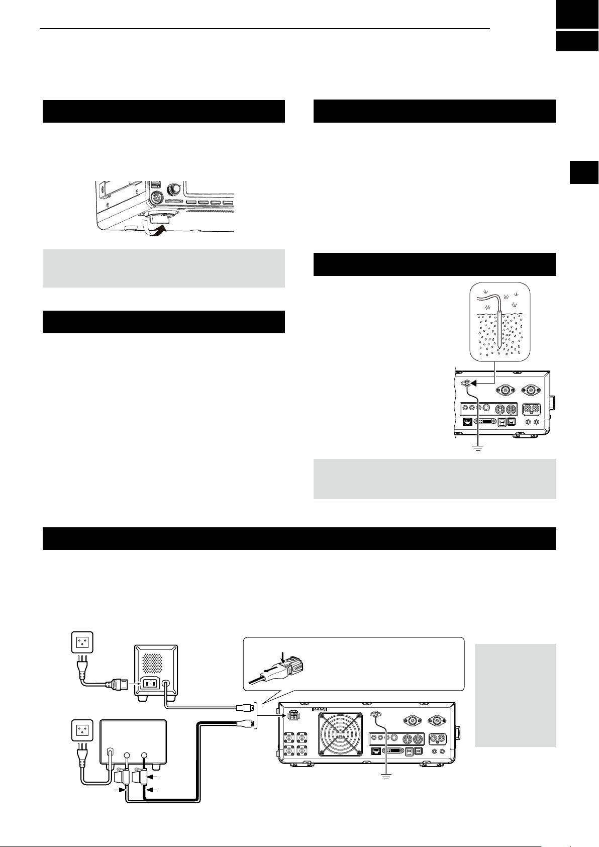
Grounding
To prevent electrical shock,
television interference (TVI),
broadcast interference (BCI)
and other problems, ground
the transceiver using the
ground terminal [GND] on
the rear panel.
For best results, connect a
heavy gauge wire or strap to
a long ground rod. Make the
distance between the [GND]
terminal and ground as short
as possible.
RWARNING! NEVER connect the [GND] terminal
to a gas or electric pipe, since the connection could
cause an explosion or electric shock.
1
2
3
4
5
6
7
8
9
10
11
12
13
14
15
Connecting an external DC power supply
Be sure that the power supply power is OFF before
connecting the DC power cable.
We recommend using Icom’s optional PS-126
(13.8 V DC/25 A) power supply.
AC Outlet
PS-126
w
AC cable
Non-Icom DC power supply
13.8 V DC/23 A
or more
_+
DC power cable
Fuse
BlackRed
q
L When using a non-Icom DC power supply, you need:
• 13.8 V DC (Capacity: At least 23 A)
• A power supply with an over current protective line and
low voltage uctuation or ripple.
To disconnect, rmly push down
the locking tab and then pull the
connector out of the socket.
2-1
GND
CAUTION:
DO NOT touch
the rear panel of
the transceiver
after transmitting
continuously
for long periods
of time. It can
become very hot.
16
17
18
19
20
21
Page 20

2
MENU
MENU
INSTALLATION AND CONNECTIONS
Connecting the antenna tuner
The AH-4 matches the IC-7610 to
the optional
AH-2b or to a long wire antenna more than 7 m/23 ft
long (usable between 3.5 and 50 MHz).
L See the AH-4 instruction manual for installation and
connection details.
L See the Advanced Manual for connecting the
optional AH-740 automatic antenna tuner.
NOTE:
• Before connecting, be sure to turn OFF the transceiver.
• While the AH-4 is connected, the IC-7610ʼs internal antenna tuner is deactivated.
HF band long wire
antenna
AH-4
GND
Connecting a Transverter
Coaxial cable (50 Ω)
[TUNER]
GND
[ANT 1]
Connect your transverter unit as described below.
L You may need to connect to [ALC], depending on the transverter.
VHF/UHF band antenna
Transverter
ANT
GND
RX RX
TRV
TX TX
TRV
RF IN/OUT
[SEND]
Coaxial cable (50 Ω)
[X-VERTER]
• Set the “Transverter Function” item to ON to use the transverter operating mode.
You can also use the transverter operating mode by connecting a DC voltage to [ACC 2 (6: TRV)].
» SET > Function > Transverter Function
LYou cannot select the antenna or use the internal tuner while using the Transverter function.
• Set the offset frequency for the transverter operation.
» SET > Function > Transverter Offset
GND
[SEND]
2-2
Page 21
Linear amplier connections
INSTALLATION AND CONNECTIONS
2
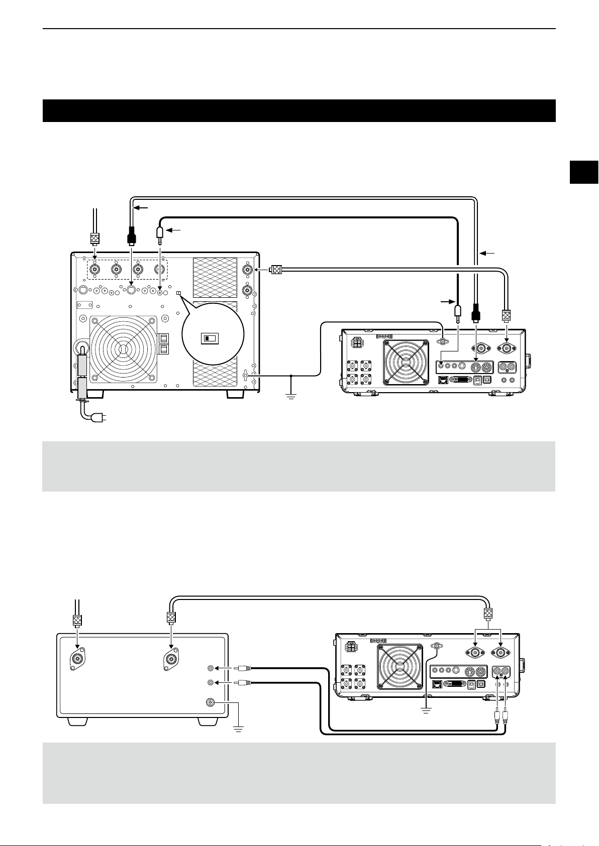
D Connecting the IC-PW1/IC-PW1EURO
See the illustration below to connect the optional IC-PW1 or IC-PW1EURO hf/50 mhz all band 1 kw linear amplifier.
Refer to the amplier’s instruction manual for operation.
To an
antenna
[ACC 1]
[REMOTE]
EXCITER
1
To an AC outlet
Non-European versions: 100~120/200~240 V
European version: 230 V
ACC cable
1 & 2
Remote control cable
[INPUT 1]
GND
Coaxial cable (50 Ω)
[ACC 2]
[REMOTE]
[ANT 1]
1
2
3
4
5
6
7
8
9
10
11
12
R WARNING! When using a linear amplier such as the IC-PW1 or IC-PW1EURO, set the RF POWER in the Multi-function
menu to keep the ALC meter in the red zone.
LSee page 3-8 for details on the RF POWER settings.
LSee page 3-9 for details on the ALC zone settings.
D Connecting a non-Icom linear amplier
See the illustration below to connect a non-Icom linear amplier.
L We recommend that you use a linear amplier with a specied input power of 100 watts or more. If you use an amplier with
a specied drive level of less than 100 watts, adjust the IC-7610’s output power to the specied level before transmitting.
Otherwise the linear amplier may be damaged.
To an antenna
Non-Icom
linear amplier
RF OUT RF IN
Coaxial cable (50 Ω)
ALC
SEND
GND
GND
GND
[ANT1]
or
[ANT2]
[SEND][ALC]
13
14
15
16
17
18
19
20
21
R WARNING!
• The maximum signal level of the [SEND] jack is 16 V/0.5 A DC, and 250 V/200 mA with the “MOSFET” setting (p. 13-2).
Use an external unit if your non-Icom linear amplier requires a control voltage and/or current greater than specied.
• The ALC input level must be in the range 0 to –4 V. The transceiver does not accept a positive voltage. Non-matched ALC
and RF power settings could overheat or damage the linear amplier.
2-3
Page 22
3
POWER
POWER
AF RF/SQL
MAIN DIAL
QUICK
AF RF/SQL
AF RF/SQL
AF RF/SQL
AF RF/SQL
SPEED
PITCH
EXIT
BASIC OPERATION
When rst applying power
Before turning ON your transceiver for the rst time,
make sure all connections are correctly made.
q
w
e
r
q MAIN
w MAIN
e SUB
r SUB
(inner): Fully counterclockwise
(outer): 12 o’clock
(inner): Fully counterclockwise
(outer): 12 o’clock
Turning power ON or OFF
After all connections are made, set the dials to the
positions described below.
t
y
KEY
SPEED
KEY
PITCH
(inner): Fully counterclockwise
(outer): 12 o’clock
t
y
TIP: When you turn OFF the transceiver, it saves the
current settings. Therefore, when you turn ON the
transceiver again, it starts with the same settings.
Adjusting the volume level
z To turn ON the transceiver, push
z To turn OFF the transceiver, hold down
.
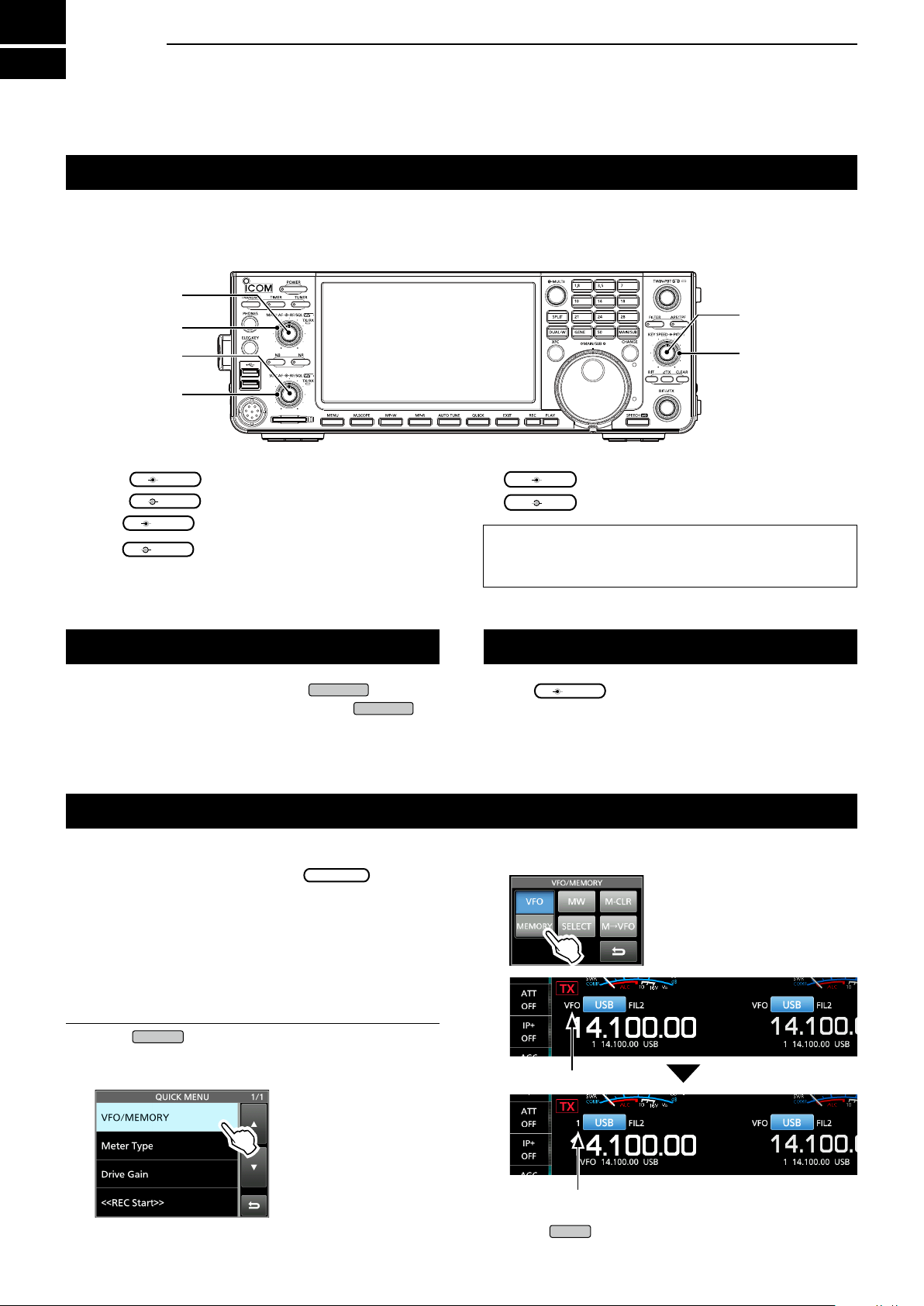
Rotate
for
2 seconds until “POWER OFF...” is displayed.
Selecting the VFO and Memory modes
VFO mode
You can set a frequency by rotating
.
L Using the VFO mode may be easier for the rst
initial operation.
Memory mode
You can recall a frequency that you have memorized
on the MEMORY list.
Selecting the VFO mode or Memory mode
1. Push
• The QUICK MENU screen is displayed.
.
2. Touch “VFO/MEMORY.”
3. Touch [VFO] or [Memory] to select the mode.
(inner) to adjust the volume level.
VFO indicator
VFO mode screen
3-1
Memory channel number
4. Push
Memory mode screen
to close the VFO/MEMORY screen.
Page 23
Selecting the Main and Sub bands
MAIN/SUB
DUAL-W
DUAL-W
MAIN DIAL
MAIN DIAL
CHANGE
MAIN/SUB
DUAL-W
CHANGE
BASIC OPERATION
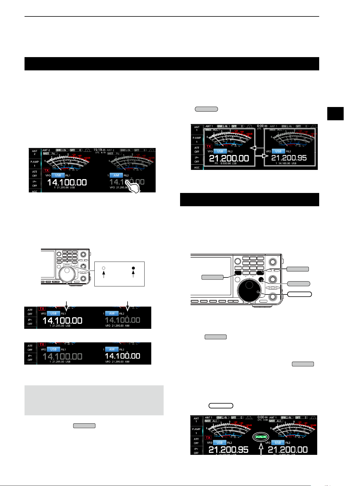
3
The IC-7610 has 2 identical receivers, Main and
Sub. The Main band is displayed on the left side of
the screen, and the Sub band is displayed on the
right side. Some functions can only be applied to the
selected band, and you can transmit on only the Main
band (except in Split Frequency operation).
To select the Main band or Sub band, touch the
frequency readout.
• The selected band’s frequency readout is displayed clearly,
and the frequency of the non-selected band is grayed.
• The selected band’s indicator lights as described below.
Example: When the Sub band is selected, the MAIN/SUB
indicator lights on the Sub band side.
D Switching the Main band and Sub band
You can switch the Main band and Sub band settings,
such as the operating frequency, mode, and so on.
Push
• The Main and Sub band settings are switched.
.
Dualwatch operation
Dualwatch simultaneously monitors two frequencies.
The IC-7610 has 2 independent receiver circuits, the
Main and Sub bands, so that you can use Dualwatch
with no compromises, even on different bands and
modes.
1
2
3
4
5
6
7
8
9
10
11
12
MAIN/SUB
Not lit
Main Sub
The Main band is selected.
The Sub band is selected.
NOTE: The Sub band readout is activated during
Split operation or Dualwatch operation.
• See page 4-9 for details on Split operation.
• See the right column for details on Dualwatch operation.
L You can also push
Sub band.
to select the Main band or
Lit
D Using the Dualwatch operation
1. Push
operation.
• “DUAL-W” is displayed.
L To equalize the Sub band frequency and mode
to those of the Main band, hold down
for 1 second. This Quick Dualwatch function can
be turned OFF in the Others set screen.
(p. 8-3)
2. Touch the frequency readout of the band you want
to set the frequency.
3. Rotate
briefly to start the Dualwatch
to set the frequency.
13
14
15
16
17
18
19
20
21
Displayed
3-2
Page 24
3
MENU
BASIC OPERATION
Selecting the operating band
D Selecting the operating band on the
keypad
(Example: Selecting 14 MHz in the Main band.)
1. Touch the Main band’s frequency readout.
2. Push 14 on the band keypad.
Keypad
• The 14 MHz band frequency is displayed.
D Selecting the operating band on the
screen
(Example: Selecting 21 MHz in the Main band.)
1. Touch the MHz digits to display the BAND
STACKING REGISTER screen.
2. Touch [21].
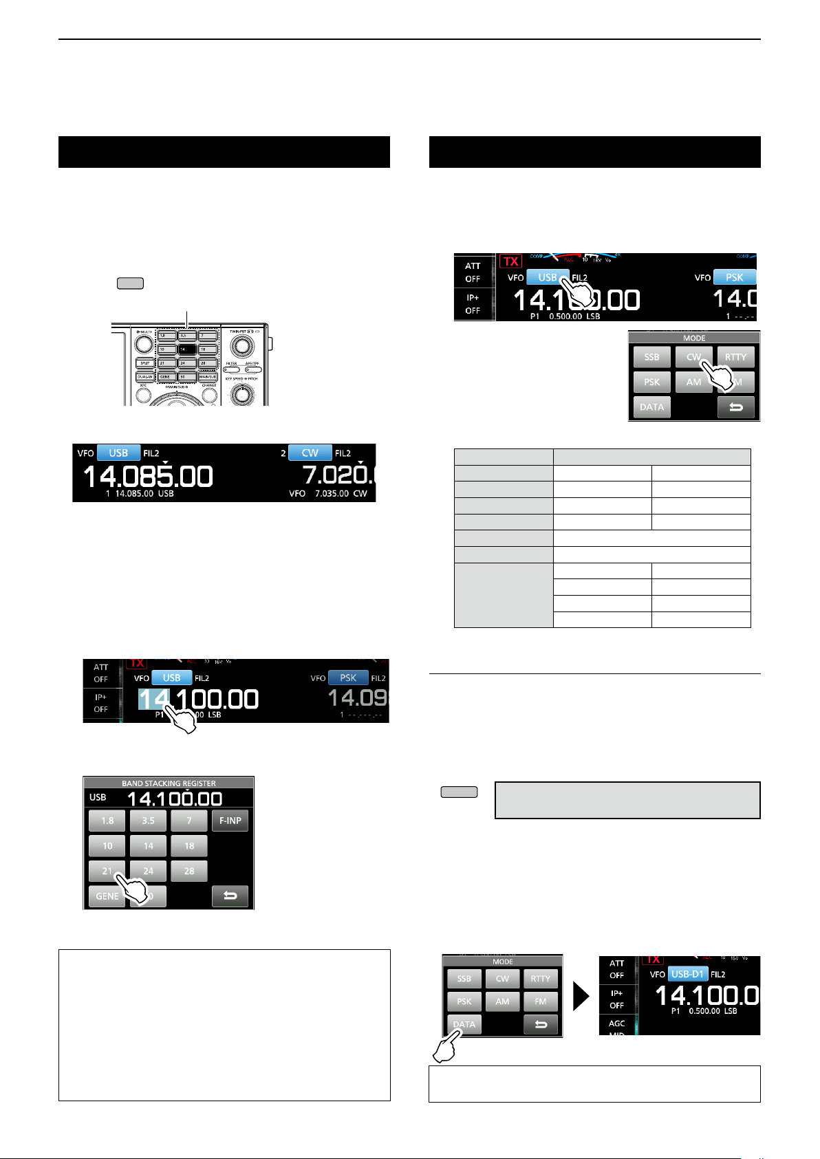
Selecting the operating mode
You can select the SSB, CW, RTTY, PSK, AM, or FM
modes.
1. Touch the mode icon.
2. Touch the mode key.
L In the SSB, AM or FM mode,
the [DATA] key is displayed.
• Operating mode selection list
Mode key Operating mode
[SSB] LSB USB
[CW] CW CW-R
[RTTY] RTTY RTTY-R
[PSK] PSK PSK-R
[AM] AM
[FM] FM
LSB LSB-D
[DATA]
Selecting the Data mode
You can operate in the Data mode in the SSB, AM and
FM modes. The Data mode enables you to operate in
these modes with input from various connectors, even
if the microphone is connected.
L When the data mode is selected, you can select the
connector that will input the modulation signal. (p. 8-6)
» SET > Connectors >
DATA OFF MOD, DATA1 MOD ~ DATA3 MOD
USB USB-D
AM AM-D
FM FM-D
About the Band Stacking Register:
The band stacking register provides 3 memories for
each band key to store frequencies and operating
modes.
Sequentially select the registered memories:
z Repeatedly push a band key on the keypad.
z Repeatedly touching a band key on the BAND
STACKING REGISTER screen for 1 second.
z Select the connector(s) to input the modulation signal.
(Example: USB-D mode)
1.
While the USB mode is selected, touch the mode icon.
2. Touch [ DATA].
• [USB-D1] is displayed.
• The selected connector will be used to input the
modulation signal.
TIP: See page 36 in the Advanced Manual for
details on using the AFSK Data mode.
3-3
Page 25

Setting the frequency
MAIN DIAL
MAIN DIAL
BASIC OPERATION
3
D Using the Main Dial
1. Select the operating band. (Example: 21 MHz)
2. Rotate
L is displayed when you set an amateur radio
frequency, and
dashes) is displayed when you set a frequency
outside the Ham band, or outside your set Band
Edges.
.
(“TX” with a border of short
D Setting the Tuning Step function
You can set
band. This is convenient to change the operating
frequency faster or slower. The following steps are set
as default.
• SSB/CW/RTTY/PSK (TS OFF): 10 Hz
• AM (TS ON): 1 kHz
• FM (TS ON): 10 kHz
Touch the kHz digits to turn the Tuning Step function
ON or OFF.
L The Tuning Step function’s icon “▼” is displayed above
the 1 kHz digit when the function is ON.
’s tuning step for each operating
D Changing the Tuning Step
When the Tuning Step function is ON, you can change
the tuning steps for each operating mode.
1. Select the desired operating mode.
2. Touch the kHz digit for 1 second.
3. Touch the tuning step. (Example: 0.1 k)
• The tuning step is set and returns to the previous
screen.
The Tuning
Step function
is ON.
D Using the 1 Hz step Fine Tuning function
You can use the minimum tuning step of 1 Hz for
ne tuning in the SSB, CW and RTTY modes as the
default.
Touch the Hz digits for 1 second to turn the Fine
Tuning function ON or OFF.
The 1 Hz digit
is displayed.
1
2
3
4
5
6
7
8
9
10
11
12
13
14
15
16
17
18
19
20
21
L When using the [UP]/[DN] keys on the microphone,
the frequency changes in 50 Hz steps with the Fine
Tuning function ON or OFF.
The Tuning Step
function is ON.
3-4
Page 26

3
EXIT
MENU
EXIT
MAIN DIAL
MENU
BASIC OPERATION
Setting the frequency (Continued)
D Using the 1/4 Tuning function
With the Tuning Function OFF, turn ON the 1⁄4
Tuning function to reduce the tuning speed to 1⁄4 of
the normal speed, for ner tuning in the SSB-D, CW,
RTTY and PSK modes.
1. Push
2. Touch [1/ 4].
3. Push
.
to close the MENU screen.
1/4 Tuning
function ON
D Directly entering a frequency
You can directly enter a frequency using the keypad.
Entering the operating frequency
1. Touch the MHz digits.
(Example: 14)
2. Touch [F-INP].
• Opens the F-INP screen.
3. Start by entering the MHz digits.
LTo clear the entry, touch [CE].
L To clear the entry and return to the previous screen,
push
4. Touch [ENT] to save the entered frequency.
• Closes the F-INP screen.
.
D Using the Auto Tuning Step function
The tuning step automatically changes, depending on
the rotating speed of
L You can change the Auto Tuning Step function settings in
the following menu. (p. 8-4)
» SET > Function > MAIN DIAL Auto TS
.
L If you touch [ENT] when the digits under 100 kHz are
not entered, “0” will be automatically entered into the
digits that are blank.
Entry examples
• 14.025 MHz: [1], [4], [•(−)], [0], [2], [5], [ENT]
• 18.0725 MHz: [1], [8], [•(−)], [0], [7], [2], [5], [ENT]
• 730 kHz: [0], [•(−)], [7], [3], [ENT]
• 5.100 MHz: [5], [•(−)], [1], [ENT]
• 7.000 MHz: [7], [ENT]
• Changing from 21.280 MHz to 21.245 MHz:
[•(−)], [2], [4], [5], [ENT]
3-5
Page 27

Setting the frequency (Continued)
QUICK
MAIN DIAL
SPEECH
MENU
BASIC OPERATION
3
Entering a Split Frequency Offset
1. On the F-INP screen, enter the Split Frequency
Offset.
LTo enter a minus shift direction, touch [•(−)].
L Enter an offset between −9.999 MHz and +9.999 MHz
(1 kHz steps).
[SPLIT] or [-SPLIT]
is displayed
Touch for -Split
Entry examples
• 10 kHz: [1], [0], [SPLIT]
• −1.025 MHz: [•(−)], [1], [0], [2], [5], [−SPLIT]
2. To save the entry, touch [SPLIT] or [−SPLIT].
• Closes the F-INP screen, and the Split function is
automatically turned ON.
The Split function is ON.
Entering a Memory channel
1. Push
2. Touch [MEMORY] to select the Memory mode.
3. Touch the MHz digits.
4. Touch [F-INP].
, and touch “VFO/MEMORY.”
Memory mode
1
2
3
4
5
6
7
8
9
10
11
12
Shifted by the offset amount.
Dial Lock function
The Dial Lock function prevents frequency changes
caused by accidently rotating
LThis function electronically locks the dial.
Hold down
Lock function ON or OFF.
• “ ” is displayed while the function is ON.
• During Split Frequency operation, the Split Lock function
may be turned ON. (p. 4-10)
» SET > Function > Lock Function
for 1 second to turn the Dial
.
5. Enter a Memory channel number between 1 and
99. (Example: Memory channel 5)
L If you want to set a Program Channel number (P1 or
P2), enter “100” for P1, and “101” for P2.
6. Touch [MEMO] to save the entered channel.
• Closes the F-INP screen.
Hold down
13
14
15
16
17
18
19
20
21
3-6
Page 28

3
AF RF/SQL
AF RF/SQL
AF RF/SQL
AF RF/SQL
AF RF/SQL
MENU
BASIC OPERATION
RF gain and SQL level
Rotate
SQL level.
By default, rotating to the left (when set to the 12
o’clock position) adjusts the RF gain, and rotating to
the right adjusts the squelch level, as described below.
Squelch is open
RF gain
adjustable range
is displayed
Minimum RF gain
RF gain
You can adjust the receive sensitivity.
• If a strong interfering signal is received, rotate
RF gain.
L “RFG” is displayed to indicate that the gain is
reduced.
L If a strong signal is received and “OVF” (Overow)
appears, reduce the RF gain until “OVF” disappears.
(outer) to adjust the RF gain and
Noise squelch (FM mode)
Maximum RF gain
S-meter squelch
adjustable range
Maximum S-meter
squelch
(outer) counterclockwise to reduce the
Meter display
D Selecting the Meter readout
Select one of the 6 different transmit parameters
(Po, SWR, ALC, COMP, Vd and Id) to display during
transmit.
Touch the meter to display one of the meters.
The selected meter’s icon is displayed.
Signal strength
Id
Power level
SWR
Compression level
VdALC level
Squelch (SQL) level
There are 2 types of squelch, depending on the
operating mode.
• Noise squelch
Rotate the
disappears and the TX/RX indicator goes OFF.
• S-meter squelch
The S-meter squelch disables the audio output from
the speaker or headphones when the received signal is
weaker than the specied S-meter squelch level.
Rotate the
position to increase the S-meter threshold level.
L You can change the
“RF/SQL Control.” (p. 8-3)
» SET > Function > RF/SQL Control
(outer) until the noise just
clockwise from the 12 o’clock
(outer) control type in
D About the Multi-function meter
S: Displays the receiving signal strength level.
Po: Displays the relative RF output power.
SWR: Displays the SWR of the antenna at the
selected frequency.
ALC: Displays the ALC level. When the meter
movement shows the input signal level
exceeds the allowed level, the ALC limits the
RF power to suppress signal distortion. In
such cases, decrease the microphone gain
level.
COMP: Displays the compression level when the
speech compressor is used.
V
d: Displays the drain voltage of the nal amplier
MOS-FETs.
I
d: Displays the drain current of the nal amplier
MOS-FETs.
TEMP: Displays the temperature of the nal amplier
MOS-FETs.
3-7
Page 29

Meter display (Continued)
EXIT
MULTI
TRANSMIT
MULTI
TRANSMIT
BASIC OPERATION
3
D Displaying the Multi-function meter
You can simultaneously display all the parameters.
L The TEMP meter is also displayed on the Multi-function
meter.
z Touch the meter for 1 second to display the
Multi-function meter.
L To close the Multi-function meter, touch the meter for 1
second again.
z While the Multi-function meter is displayed, touch
[P-HOLD] to turn ON the Peak Level Hold function.
• “P-HOLD” is displayed on the Multi-function meter
window title.
L To turn OFF, push
.
Displayed when Peak Hold function is ON.
Adjusting the transmit output power
Before transmitting, monitor your selected operating frequency to make sure you do not cause interference to other stations on
the same frequency. It is good amateur practice to listen rst, and then, even if nothing is heard, ask if the frequency is in use
once or twice, before you start operating.
1
2
3
4
5
6
7
8
9
10
11
12
D Adjusting the transmit output power
1. Set the operating mode to SSB, CW, RTTY, PSK
or FM. (p. 3-3)
2. Touch the meter several times to display the Po
me ter.
• is displayed.
3. Push
4. Hold down [PTT] (or push
• The Po meter level changes according to your voice
level in the SSB mode.
• The TX/RX indicator lights red and
L Tune the antenna before you view the power meter
level on the meter. If the antenna is not tuned properly,
the meter will not reect the power level.
to open the Multi-function menu.
).
is displayed.
5. Touch “RF POWER.”
6. Rotate
to between 0 and 100%.
• The Po meter displays the RF output power in a
percentage. It becomes the S-meter while receiving.
7. Release [PTT] (or push
• Returns to receive.
to adjust the transmit output power
again).
13
14
15
16
17
18
19
20
21
3-8
Page 30

3
MULTI
MULTI
TRANSMIT
TRANSMIT
BASIC OPERATION
Adjusting the microphone gain
Adjust the microphone gain as described below.
1. Set the operating mode to SSB, AM or FM.
(p. 3-2)
2. Push
3. Touch “MIC GAIN.”
4. Hold down [PTT] on the microphone.
• The TX/RX indicator lights red and is displayed.
5. Rotate
6. Release [PTT].
• Returns to receive
InformationL
• In the SSB mode, touch the TX meter to select the
ALC meter, and adjust until the meter reading swings
between 30 to 50% of the ALC scale, when speaking
into the microphone at your normal voice level.
• In the AM or FM mode, check the audio clarity with
another station, or use the Monitor function (p. 4-7).
to display the Multi-function menu.
to adjust the microphone gain.
Basic transmission
1. Hold down [PTT] (or push
• The TX/RX indicator lights red and is displayed
while transmitting.
2. Release [PTT] (or push
• Returns to receive.
) to transmit.
again).
3-9
Page 31

RECEIVING AND TRANSMITTING
RIT
RIT/
TX
CLEAR
RIT
RIT
XFC
RIT
XFC
MULTI
4
Preampliers
The preamps amplify received signals in the receiver
front end to improve the signal-to-noise ratio and
sensitivity. A preamp is used when the received
signals are weak.
L Each band memorizes the previously used Preamplier
setting.
Touch [P.AMP].
L Each touch sequentially selects “P.AMP 1,” “P.AMP 2,”
and “P.AMP OFF.”
Wide dynamic range preamplier.
P.AMP 1
P.AMP 2
NOTE:
• When you use the preamp while receiving strong
signals, the receiving signal may be distorted. In such
case, turn OFF the preamp.
• While the Digital Selector is ON, “P.AMP OFF” is xed,
and you cannot select “P.AMP 1” or “P.AMP 2.”
It is most effective for the HF low bands.
• Gain is approximately 12 dB.
High-gain preamplier.
It is most effective for the higher bands.
• Gain is approximately 20 dB.
RIT function
The RIT (Receive Increment Tuning) function
compensates for differences in the transmit
frequencies of other stations.
The function shifts your Main bandʼs receive frequency
up to ±9.99 kHz without shifting your transmit
frequency.
1. Push
L While using the Fine Tuning function (p. 3-4), the RIT
frequency is displayed in 4 digits, instead of 3.
2. Rotate
the transmitting station’s frequency.
L You can reset the RIT frequency to “0.00” by holding
down
L You can add the frequency shift to your operating
frequency by holding down
3. When you have finished communicating, push
to turn ON the RIT function.
RIT frequency
to set the RIT frequency to match
for 1 second.
for 1 second.
to turn the RIT function OFF.
1
2
3
4
5
6
7
8
9
10
11
12
13
Attenuator
The Attenuator prevents a signal from becoming
distorted when a very strong signal is being received
near your operating frequency, or when a very strong
electric eld, such as from a broadcasting station.
Touch [ATT] to sequentially set the Attenuator up to 18
dB in 6 dB steps.
You can also set the Attenuator in 3 dB steps:
1. Touch [ATT] for 1 second to open the ATT menu.
Displayed
D Using the RIT Monitor function
When the RIT function is ON, you can monitor your
operating frequency while holding down
L While monitoring:
• The RIT function is temporarily OFF.
• The Noise Reduction, Notch lter and Twin PBT
settings are temporarily OFF.
.
14
15
16
17
18
19
20
21
Rotate
2.
up to 45 dB.
to adjust the attenuator level of
4-1
Page 32

4
MAIN DIAL
EXIT
RECEIVING AND TRANSMITTING
AGC function control
The AGC (Automatic Gain Control) controls receiver
gain to produce a constant audio output level, even
when the received signal strength varies greatly.
D Selecting the AGC time constant
preset value
The transceiver has FAST, MID and SLOW preset
AGC settings for all modes, except for the FM mode.
1. Select the operating mode.
(Example: SSB)
2. Touch [AGC] to sequentially select FAST, MID or
SLOW.
LFAST is xed in the FM mode.
D Setting the AGC time constant
You can set the preset AGC time constant.
1. Select the operating mode.
(Example: SSB)
2. Touch [AGC] for 1 second.
• Opens the AGC screen.
3. Touch FAST, MID or SLOW.
4. Rotate
L You can reset to the default settings by touching
[DEF] for 1 second.
5. To close the AGC screen, push
to set the time constant.
.
• Selectable AGC Time constant (unit: seconds)
Mode Default Adjustable time constant
0.3
LSB
USB
CW
RTTY
PSK
AM
FM 0.1
NOTE: When you are receiving weak signals, and a strong
signal is momentarily received, the AGC function quickly
reduces the receiver gain. When that signal disappears,
the transceiver may not receive the weak signal because
of the AGC action. In that case, select FAST, or touch
[AGC] for 1 second to open the AGC screen, and then
select OFF.
2.0
6.0
0.1
0.5
1.2
3.0
5.0
7.0
(FAST)
(MID)
(SLOW)
(FAST)
(MID)
(SLOW)
(FAST)
(MID)
(SLOW)
(FAST)
OFF, 0.1, 0.2, 0.3, 0.5, 0.8, 1.2,
1.6, 2.0, 2.5, 3.0, 4.0, 5.0 or 6.0
OFF, 0.1, 0.2, 0.3, 0.5, 0.8, 1.2,
1.6, 2.0, 2.5, 3.0, 4.0, 5.0 or 6.0
OFF, 0.3, 0.5, 0.8, 1.2, 1.6, 2.0,
2.5, 3.0, 4.0, 5.0, 6.0, 7.0 or 8.0
Fixed
4-2
Page 33

Using the Twin PBT
TWIN PBT
FILTER
EXIT
TWIN PBT
PBT1
PBT2
TWIN PBT
TWIN PBT
TWIN PBT
FILTER
TWIN PBT
TWIN PBT
RECEIVING AND TRANSMITTING
4
SSB, CW, RTTY, PSK and AM modes
To reject interference, the Twin PBT (Passband
Tuning) narrows the IF passband width by
electronically shifting the IF frequency slightly above
or below the IF center frequency. The IC-7610 uses
DSP for the PBT function.
1. Rotate
in the opposite direction from each other.
InformationL
• Match both the
outer (PBT2) lters before operating the Twin PBT.
• Rejects interference of both higher and lower
passbands.
• If you rotate the control too much, the received
audio may not be heard because the passband
width is too narrow.
• Displays the passband width and shift value.
• Hold down
PBT setting.
• The PBT is adjustable in 50 Hz steps in the SSB,
CW, and RTTY modes, and 200 Hz in the AM
mode. In this case, the center shift value changes
in 25 Hz steps in the SSB, CW, and RTTY modes,
and 100 Hz in the AM mode.
• Rotating both the inner and outer controls together
to the same position shifts the IF left or right.
CLR
inner (PBT1) and outer (PBT2)
CLR
(inner) (PBT1) and
CLR
for 1 second to clear the
• When rotating
Filter width Shifting value
• The FILTER screen when rotating
CLR
Passband width
(Duplicated with PB1 and PB2)
Selected
IF lter
CLR
CLR
1
2
3
4
5
6
7
8
9
10
11
12
13
2. Hold down
current passband width and shift frequency.
• Opens the FILTER screen.
3. To close the FILTER screen, push
NOTE: While rotating
This comes from the DSP unit and does not indicate an
equipment malfunction.
PBT is OFF
for 1 second to display the
.
CLR
, you may hear noise.
Cutting the
lower passband
PBT2
PBT1
SFT: Shift value
IF center frequency
Cutting both higher and
lower passbands
PBT2
PBT1
Passband Passband
PBT2
PBT1
Passband center frequency
Passband width
BW:
14
15
16
17
18
19
20
21
IF center frequency
Interference
Desired
signal
4-3
Interference Desired
signal
Interference
Page 34

4
FILTER
MAIN DIAL
EXIT
FILTER
EXIT
RECEIVING AND TRANSMITTING
Selecting the IF lter
The transceiver has 3 IF lter passband widths for
each mode, and you can select them on the FILTER
screen. You can set the IF lter to FIL 1 (wide), FIL 2
(mid) or FIL 3 (narrow).
1. Select the operating mode.
(Example: USB)
2. Hold down
• Opens the FILTER screen.
for 1 second.
3. Touch FIL 1 (wide), FIL 2 (mid) or FIL 3 (narrow).
4. Touc h [ BW ] .
• Selects the passband width mode.
5. Rotate
L You cannot change the passband width in the FM or
FM-D mode.
L When you change the passband width, the Twin PBT
setting value is reset to the center position.
to select the passband width.
Mode IF lter Selectable range (steps)
SSB
SSB-D
CW
PSK
RTTY
AM
AM-D
FM
FM-D
FIL 1 (3.0 kHz)
FIL 2 (2.4 kHz)
FIL 3 (1.8 kHz)
FIL 1 (3.0 kHz)
FIL 2 (1.2 kHz)
FIL 3 (500 Hz)
FIL 1 (1.2 kHz)
FIL 2 (500 Hz)
FIL 3 (250 Hz)
FIL 1 (2.4 kHz)
FIL 2 (500 Hz)
FIL 3 (250 Hz)
FIL 1 (9.0 kHz)
FIL 3 (3.0 kHz)
FIL 1 (15 kHz)
FIL 3 (7.0 kHz)
50 Hz to 500 Hz (50 Hz)/
600 Hz to 3.6 kHz (100 Hz)
50 Hz to 500 Hz (50 Hz)/
600 Hz to 3.6 kHz (100 Hz)
50 Hz to 500 Hz (50 Hz)/
600 Hz to 3.6 kHz (100 Hz)
50 Hz to 500 Hz (50 Hz)
600 Hz to 2.7 kHz (100 Hz)
200 Hz to 10.0 kHz (200 Hz)FIL 2 (6.0 kHz)
FixedFIL 2 (10 kHz)
Selecting the IF lter shape
Displayed when the selected band width is 500 Hz
or narrower, in the SSB or CW mode.
Touch for 1 second to reset to default
6. Touch [ BW ].
• Cancels the passband width mode.
7. Repeat steps 3 to 5 to set the passband width for
other modes except for the FM and FM-D modes.
8. To close the FILTER screen, push
TIP: When you set the IF lter to FIL2 or FIL3 in the FM
mode, the transceiver will transmit in the FM narrow mode.
.
You can independently set the DSP lter shape to soft
or sharp for each operating mode.
1. Set the operating mode to SSB or CW.
(Example: USB)
2. Hold down
• Opens the FILTER screen.
for 1 second.
3. Select FIL1 (wide), FIL2 (mid) or FIL3 (narrow).
4. Touch [SHARP] or [SOFT].
5. To close the FILTER screen, push
• SHARP
This selection is to emphasize the passband width of
the lter. The lter has an almost ideal shape factor.
Signals of the out of passband are extremely ltered
out and it gives you better audio quality.
• SOFT
The lter shoulders are roundly formed as in analog
lters. This decreases noise components in the
high and low frequencies of the lter passband
and increases the S/N of the target signal. These
characteristics play an effective role in picking up
very weak signals in the 50 MHz band, for example.
The shape factor is kept, and the sharpness of the
bandpass is excellent.
4-4
.
Page 35

RECEIVING AND TRANSMITTING
NB
NB
NB
MULTI
MULTI
NR
NR
NR
MULTI
EXIT
4
Noise Blanker
The Noise blanker eliminates pulse-type noise such
as the noise from car ignitions.
The Noise blanker cannot be used in the FM mode.
Push
• The Noise Blanker indicator on
NOTE: When using the Noise Blanker, received signals
may be distorted if they are excessively strong, or the
noise is other than a pulse type. In that case, turn OFF the
Noise Blanker, or shallow the DEPTH on the NB menu.
See the instruction below for details.
D Adjusting the NB level and time
To deal with various types of noise, you can adjust the
attenuation level and the blanking depth and width in
the NB menu.
1. Hold down
• Turns ON the Noise Blanker and opens the NB menu.
2. Touch the adjusting item.
to turn the Noise Blanker ON or OFF.
lights.
The indicator lights.
for 1 second.
Noise Reduction
The Noise Reduction reduces random noise
components and enhances signal audio.
Push
• The Noise Reduction indicator on
D Adjusting the Noise Reduction level
Adjust the Noise Reduction level to where noise is
reduced but the received signal is not distorted.
1. Hold down
• Turns ON the Noise Reduction and opens the NR
2. Rotate
level to between 0 and 15.
L Adjust to a higher level to increase the reduction
to turn the Noise Reduction ON or OFF.
lights.
The indicator lights.
for 1 second.
menu.
to adjust the Noise Reduction
level, and to a lower level to decrease it.
1
2
3
4
5
6
7
8
9
10
11
12
13
3. Rotate
(Example: 8)
4. Push
LEVEL (Default: 50%)
Adjust the level where the Noise Blanker activates
between 0 and 100%.
DEPTH (Default: 8)
Adjust the noise attenuation depth between 1 and 10.
WIDTH (Default: 50)
Adjust the blanking duration time between 1 and 100.
to adjust the item.
to set and close the NB menu.
Noise Reduction OFF
NR level 0
Noise components Desired signal (CW)
3. Push
to close the NR menu.
Noise Reduction ON
NR level 4
14
15
16
17
18
19
20
21
4-5
Page 36

4
MENU
MULTI
EXIT
MAIN DIAL
MENU
EXIT
RECEIVING AND TRANSMITTING
Digital Selector
You can manually adjust the center frequency of
the automatic preselector using the Digital Selector
function.
The automatic preselector adds selectivity ahead of
the 1st mixer. This reduces intermodulation distortion
from nearby strong signals. The automatic preselector
tracks the frequency tuning by changing its resonant
frequency in discrete steps. The Digital selector is
used within the ham band, except for the 50 MHz
band.
D Turning ON the Digital Selector function
1. Push
2. Touch [DIGI-SEL] to turn ON the Digital Selector
function ON.
LTouching [DIGI-SEL] to turn the function ON or OFF.
to open the MENU screen.
Notch Filter
The IC-7610 has Auto Notch and Manual Notch
functions.
Auto Notch can be used in the SSB, AM and FM
modes, and Manual Notch can be used in the SSB,
CW, RTTY, PSK, and AM modes.
D Selecting the Notch function type
1. Push
2. Touch [NOTCH] to select the Notch function type.
L Touching [NOTCH] changes between “AN (Auto
Notch),” “MN (Manual Notch)” and OFF.
• “AN” is displayed when the Automatic Notch function
is ON, and “MN” is displayed when the Manual Notch
function is ON.
.
D Adjusting the center frequency
1. While the MENU screen is displayed,
touch [DIGI-SEL] for 1 second.
• The Multi-function menu is displayed, and the Digital
Selector adjustment is automatically selected.
2. Rotate
3. To close the Multi-function menu, push
NOTE:
• When you rotate
is ON, mechanical noise may be heard due to the
switching noise from internal relays.
• The P.AMP 1 or P.AMP 2 preamps cannot be used while
using the Digital Selector.
to adjust the center frequency.
while the Digital Selector
3. To close the MENU screen, push
.
D Auto Notch function
The Auto Notch automatically attenuates beat tones,
tuning signals, and so on.
L “AN” is displayed when the Automatic Notch
function is ON.
.
4-6
Page 37

RECEIVING AND TRANSMITTING
MULTI
MENU
MULTI
4
Notch Filter (Continued)
D Manual Notch function
The Manual Notch attenuates beat tones, tuning
signals and so on by adjusting the Notch lter’s center
frequency.
1. Touch [NOTCH] for 1 second.
• The Multi-function menu is displayed, and the Notch
position setting is automatically selected.
Monitor function
The Monitor function enables you to monitor your
transmit audio. Use this function to check the voice
characteristics while adjusting the transmit audio
parameters.
L You can hear the CW sidetone regardless of the Monitor
function setting.
1. Select the operating mode that you want to
monitor. (Example: AM)
2. Push
• Opens the MENU screen.
3. Touch [MONI] to turn ON the Monitor function.
LTouching [MONI] turns the Monitor function ON or OFF.
.
1
2
3
4
5
6
7
8
9
10
2. Rotate
frequency.
NOTE: While adjusting, noise may be heard.
This comes from the DSP unit but it does not indicate
an equipment malfunction.
to manually attenuate the
L Touching [NOTCH WIDTH]
changes the Manual Notch lter
width between “WIDE,” “MID,”
and “NAR.”
4. Touch [MONI] for 1 second.
• The Multi-function menu is displayed, and the
MONITOR setting is automatically selected.
5. Rotate
audio output between 0% and 100%, while
speaking at your normal voice level.
to a
djust MONITOR to the clearest
11
12
13
14
15
16
17
18
19
20
21
NOTE: When using the VOICE DELAY set in the VOX
menu, turn OFF the Monitor function. Otherwise the
transmitted audio will echo.
4-7
Page 38

4
MULTI
AUTO TUNE
RECEIVING AND TRANSMITTING
Speech Compressor (SSB)
The Speech Compressor increases the average RF
output power, improving readability at the receiving
station. This function compresses the transmitter
audio input to increase the average audio output level.
L The function is effective for long-distance communication,
or when propagation conditions are poor.
1. Select the SSB mode.
2. Be sure the Speech Compressor is OFF.
L If it is ON, touch [COMP] to turn it OFF.
OFF
3. Touch the meter to display the ALC meter.
L Touching the meter sets the meter to Po, SWR, ALC,
COMP, V
D or ID.
Select the ALC meter.
7. Touch [COMP] for 1 second to turn the Speech
Compressor ON, and to display the COMP menu.
• The Speech Compressor Level setting is automatically
selected.
ON
8. While speaking into the microphone at your
normal voice level, adjust the Speech Compressor
level to where the COMP meter reads within the
COMP zone (10 to 20 dB range).
L If the COMP meter peaks exceed the COMP zone,
your transmitted voice may be distorted.
4. Push
to display the Multi-function menu.
5. Touch [MIC GAIN], and then adjust it by speaking
into the microphone (p. 3-9) to where the ALC
meter reads within the 30 to 50% range of the
ALC zone.
6. Touch the meter again to display the COMP
me ter.
Auto Tuning function (AM/CW)
When an off-frequency signal is received, the Auto
Tuning function tunes the signal within a ±500 Hz
range in the CW mode, or a ±5 kHz range in the AM
mode. You can use this function only in the CW and
AM modes.
COMP zone
Displayed
while tuning
1. Select the AM mode or CW mode.
2. Push
L While using the RIT function, the RIT frequency is
automatically tuned by this function.
to start the Auto Tuning.
NOTE: When receiving a weak signal, or receiving a signal
with interference, the Auto Tuning function may tune the
receiver to an undesired signal, or may not start tuning. In
such case, a warning beep sounds.
4-8
Page 39

Split frequency operation
SPLIT
XFC
SPLIT
SPLIT
RECEIVING AND TRANSMITTING
4
Split frequency operation enables you to transmit and
receive on different frequencies on the Main band and
the Sub band.
The other station My station
Transmit frequency
Receive frequency
USB mode
21.29000 MHz
USB mode
21.29500 MHz
Main band
Receive frequency
Sub band
Transmit frequency
D Using the Quick Split function
The Quick Split function enables you to automatically
equalize the Main band’s frequency and mode to the
Sub band, and then activate the Split function.
1. Set the Main’s receive frequency and operating
mode.
(Example: 21.29000 MHz in the USB mode)
2. Hold down
• The Quick Split function is turned ON, and the Split
icon is displayed.
• The Main band settings are set to the Sub band.
for 1 second.
There are 2 ways to use the Split frequency operation.
• Using the Quick Split function
• Using the receive and transmit frequencies set to the
Main band and Sub band.
D Using the receive and transmit
frequencies set to Main and Sub
1. Set Main band’s receive frequency and operating
mode.
(Example: 21.29000 MHz in the USB mode)
2. Touch the Sub band’s frequency readout to select
the Sub band, and then set the receive frequency
and the operating mode.
(Example: 21.29500 MHz in the USB mode)
1
2
3
4
5
6
7
8
9
10
11
12
13
14
3. While holding down
frequency offset between transmit and receive.
, set the operating
3. Push
• The Split function is turned ON, and the Split icon is
displayed.
L Pushing
4. Touch the Main band’s frequency readout to return
to receive on the Main band.
LThe Split frequency operation is ready to use.
.
turns the Split function ON or OFF.
15
16
17
18
19
20
21
4-9
Page 40

4
XFC
MAIN DIAL
MENU
SPEECH
XFC
MENU
MENU
MENU
MENU
FILTER
EXIT
KEY
SPEED
PITCH
RECEIVING AND TRANSMITTING
Split Lock function
To prevent accidentally changing the receive frequency by
releasing
while rotating
, use the Split Lock
function. Using both this function and the Dial Lock function
(p. 3-6) enables you to change only the transmit frequency.
1. Turn ON the Split Lock function.
» SET > Function > SPLIT > SPLIT LOCK
2. Turn ON the Split function.
3. Hold down
for 1 second to turn ON the
Dial Lock function.
4.
While holding down
Displayed when the Dial Lock function is ON.
, set the transmit frequency.
Setting the transmit lter width
Operating CW
D Setting the CW pitch control
You can adjust the received CW audio pitch and CW
side tone to suit your preference without changing the
operating frequency.
1. Select the CW mode.
2. Hold down
• The FILTER screen is displayed.
LThe FILTER screen graphically displays the CW pitch.
3. Rotate
KEY
SPEED
to 900 Hz.
for 1 second.
CW pitch frequency display
PITCH
(outer) to adjust to between 300
The transmit lter width for the SSB and SSB-D mode
can be set. Only for the SSB mode, WIDE (wide), MID
(middle) or NAR (narrow) can be selected.
To change the lter width in the SSB mode:
1. Set the operating mode to USB or LSB.
2. Touch [COMP] for 1 second.
• Opens the COMP menu on the right side of the screen.
3. Touch [ TBW ].
L Touching [TBW] sets the lter width to WIDE, MID or
NAR.
COMP menu
Screen example in the SSB mode
L The transmit lter widths are set to the following
values by default.
• SSB (WIDE): 100 Hz to 2900 Hz
• SSB (MID): 300 Hz to 2700 Hz
• SSB (NAR): 500 Hz to 2500 Hz
• SSB-D: 300 Hz to 2700 Hz
When the selected IF lter is:
• Below 500 Hz, the CW pitch frequency is
graphically changed in 5 Hz steps.
• Above 600 Hz, the CW pitch frequency is
graphically changed in 25 Hz steps.
4. To close the FILTER screen, push
.
You can change the lter width values in the
following settings. (p. 8-2)
SET > Tone Control/TBW > TX > SSB > TBW (WIDE)
»
SET > Tone Control/TBW > TX > SSB > TBW (MID)
»
SET > Tone Control/TBW > TX > SSB > TBW (NAR)
»
SET > Tone Control/TBW > TX > SSB-D > TBW
»
4-10
Page 41

SPEED
PITCH
Operating CW (Continued)
MULTI
KEY
SPEED
EXIT
RECEIVING AND TRANSMITTING
4
D Setting the keying speed
You can set the keying speed of the internal electronic
keyer.
1. Select the CW mode.
2. Rotate
to between 6 and 48 WPM (Word Per Minutes).
• The keying speed is displayed under the time display
KEY
while setting.
(inner) to set the keying speed
KEY
PITCH
SPEED
D Using the Break-in function
Use the Break-in function in the CW mode to
automatically switch between transmit and receive
when keying. The IC-7610 is capable of Semi Break-in
and Full break-in modes.
TIP: The key type is set to “Paddle” by default. You can
select the keyer type on the CW-KEY SET screen.
(p. 4-13)
Semi Break-in mode
In the Semi Break-in mode, the transceiver transmits
when keying, and then automatically returns to receive
after a preset time, after you stop keying.
1. Select the CW mode.
2. Touch [BK-IN] in the function menu to select
“SEMI.”
L Touching [BK-IN] changes between “BKIN (Semi
Break-in),” “F-BKIN (Full Break-in)” or OFF (no
indication).
1
2
3
4
5
6
7
8
9
10
11
12
Touch [BK-IN].
3. To adjust the Semi Break-in Delay time, touch
[BK-IN] for 1 second.
• Opens the BKIN menu.
4. Rotate
does not return to receive while keying.
L When you are using a paddle,
rotate
while operating the paddle. See the left column for
details.
5. To close the BKIN menu, push
to set to where the transceiver
PITCH
(inner) to adjust the key speed
.
13
14
15
16
17
18
19
20
21
4-11
Page 42

4
MENU
APF/TPF
APF/TPF
APF/TPF
APF/TPF
MULTI
EXIT
RECEIVING AND TRANSMITTING
Operating CW
D Using the Break-in function (Continued)
Full Break-in mode
In the Full Break-in mode, the transceiver
automatically transmits while keying down, and then
immediately returns to receive after keying up.
1. Select the CW mode.
2. Touch [BK-IN] in the function menu to select
“FULL.”
L Touching [BK-IN] changes between “BKIN (Semi
Break-in),” “F-BKIN (Full Break-in)” and OFF (no
indication).
Touch [BK-IN].
3. Use a straight key or paddle to operate.
L In the Full break-in mode, the transceiver automatically
returns to receive without a preset break-in delay time
after you stop keying. The transceiver receives while
keying up.
D APF (Audio Peak Filter) operation
The APF enables you to set excellent selectivity in the
CW mode. You can set the selectivity to between the
three APF passband width, WIDE, MID or NAR.
1. Select the CW mode.
2. Push
• The APF icon is displayed, and the APF indicator on
the key lights.
L Pushing
OFF.
L When the APF Type is set to “Sharp” in step 4, the
selected passband width of “320 Hz,” “160 Hz” or “80
Hz” is displayed under the APF icon for 1 second.
to turn ON the Audio Peak Filter.
turns the Audio Peak Filter ON or
D Monitoring the CW side tone
When the transceiver is in standby and the Break-In
function is OFF, you can listen to the CW side tone
without actually transmitting.
InformationL
• This enables you to match your transmit
frequency exactly to another station’s by matching
the audio tone.
• You can also use the CW side tone (be sure the
Break-in function is OFF) to practice CW sending.
• You can adjust the CW side tone level in “Side Tone
Level.”
» KEYER > EDIT/SET > CW-KEY SET >
Side Tone Level
3. Hold down
for 1 second to open the APF
menu.
4. Touch to select the item, and then set the audio
filter position, passband width, and the audio level.
POSITION: Rotate
to shift the peak
frequency of the APF. This function
enables you to avoid interference from
adjacent frequencies.
WIDTH: Touch to select WIDE, MID or NAR.
TYPE: Select the audio lter type (soft sound
or sharp sound).
AF LEVEL: Set the audio level between 0 dB and
+6 dB in 1 dB steps.
5. To close the APF menu, push
.
4-12
Page 43

Operating CW (Continued)
MENU
EXIT
RECEIVING AND TRANSMITTING
4
D About the Electronic Keyer function
You can set the Keyer Memory function settings,
paddle polarity settings, and so on of the Electronic
Keyer.
1. Open the KEYER SEND screen in the CW mode.
» KEYER
L You can select [KEYER] on the MENU screen only in
the CW mode.
2. Touch [EDIT/SET].
• Opens the EDIT/SET screen.
KEYER SEND screen
EDIT
KEYER MEMORY edit menu
You can edit the keyer memories M1
to M8.
1
2
3
4
5
6
7
8
9
10
11
12
3. Touch to select the item to set.
EDIT/SET screen
4. To close the KEYER SEND screen, push
several times.
13
KEYER 001 contest number menu
001 SET
CW-KEY SET
You can set the following items.
• Number Style
• Count Up Trigger
• Present Number
CW-KEY SET menu
You can set the following items.
• Side Tone Level
• Side Tone Level Limit
• Keyer Repeat Time
• Dot/Dash Ratio
• Rise Time
• Paddle Polarity
• Key Type
• MIC Up/Down Keyer
14
15
16
17
18
19
20
21
4-13
Page 44

5
MENU
HOLD
MAIN DIAL
SCOPE OPERATION
Spectrum scope screen
The spectrum scope enables you to display the
activity on the selected band, as well as the relative
strengths of various signals.
The transceiver has two spectrum scope modes, the
Center mode and the Fixed mode.
You can also turn the Waterfall display ON or OFF.
In addition, you can select the Mini scope to display it
in a smaller size on the screen.
• Center mode screen
Span (Display range)Span (Display range)
Center/Fixed mode icon
Display frequency (stays on Center)
Waterfall zone
FFT (Fast Fourier Transform)
Grid (frequency/level)
Band icon (Main)
scope zone
• Fixed mode screen
Edge (Upper frequency)Edge (Lower frequency)
Center/Fixed mode icon
Display frequency (mobile)
Grid (frequency/level)
Band icon (Sub)
FFT scope zoneWaterfall zone
D Marker
The marker marks the operating frequencies for both
the Main and Sub bands in the SPECTRUM SCOPE
screen.
M: The Main band marker
• Marks the Main band frequency.
S: The Sub band marker
• Marks the Sub band frequency.
T: The TX marker
• Marks the transmit frequency.
L In the Center mode, the operating frequency stays
on the center of the screen. Therefore, neither the
Main band marker on the Main scope, nor the Sub
band marker on the Sub scope are displayed.
D Using the Spectrum Scope
Display the SPECTRUM SCOPE screen.
»
SCOPE
MENU 1: Center mode
MENU 1: Fix mode
MENU 2: Center/Fix mode
Key Action
<MENU1>
<MENU2>
SPAN
EDGE
HOLD
CENT/FIX Selects the Center or Fixed mode.
MAIN/SUB Selects the Main band or Sub band.
DUAL Selects the Dual or Single scope.
EXPD/
SET
REF
SPEED
RBW
VBW
MARKER Selects various Markers.
Selects the Function menus.
In the Center mode, selects the
Touch
Touch 1 sec.
In the Fixed mode, selects the Edge frequencies.
L You can set the upper and lower edge frequencies
in the “Fixed Edges” item on the SCOPE SET
screen by touching [EXPD/SET] for 1 second.
Touch
Touch 1 sec.
Touch
Touch 1 sec.
Opens the Reference level window.
L Rotate
Selects the sweep speed.
• “” (FAST), “” (MID) or “” (SLOW).
Selects the Resolution Band Width from NAR
(narrow), MID and WIDE.
L This selection is for the lter that visually separates
the spectrum.
L When "NAR" is selected, the signals are nely
separated.
Selects the Video Band Width from NAR
(narrow) and WIDE.
L When “Wide” is selected, the line drawn on the
receive spectrum becomes wide. However, the
small edge cannot be drawn.
scope span.
• Spans: ±2.5, 5.0, 10, 25, 50, 100, 250
and 500 kHz
Resets to the ±2.5 kHz span.
Sets the Hold function to ON or OFF.
• “
Clears the Peak Hold level.
Selects the Expanded or Normal
screen.
Displays the SCOPE SET screen.
” and the marker are displayed.
Freezes the current spectrum.
to adjust the Reference level.
5-1
Page 45

Spectrum scope screen (Continue)
M.SCOPE
M.SCOPE
MENU
HOLD
SCOPE OPERATION
5
D Displaying the Mini scope screen
The Mini scope screen can be simultaneously
displayed with another function display, such as the
RTTY DECODE screen or AUDIO SCOPE screen.
Push
LPushing it again closes the Mini scope screen.
TIP: Holding down
scope screen, and pushing it again returns to the
Mini scope screen.
.
displays the spectrum
Audio scope screen
This audio scope enables you to display the received
signal’s frequency components on the FFT scope, and
its waveform components on the Oscilloscope. The
FFT scope also has a waterfall display.
Example: Displaying the Mini scope screen while the
ANTENNA screen is displayed.
• AUDIO SCOPE screen
OscilloscopeFFT Scope zone
Band icon (Main)
1
2
3
4
5
6
7
8
9
10
11
12
D Using the Audio scope
Display the AUDIO SCOPE screen.
» AUDIO
Waterfall zone
Key
MAIN/SUB Selects the Main or Sub band.
Selects the Attenuator for the FFT
Touch
ATT
Touch for
1 second
HOLD Touch
LEVEL
TIME
SET Displays the AUDIO SCOPE SET screen.
Selects the Oscilloscope level.
• 0, –10, –20, or –30 dB
Selects the Oscilloscope sweep time.
• 1, 3, 10, 30, 100, or 300 ms/Div
scope.
Turns OFF the attenuator. (0 dB)
Turns the Hold function ON or OFF.
Action
• 0 (OFF), 10, 20, or 30dB
• “
” is displayed and freezes
the current audio spectrum.
13
14
15
16
17
18
19
20
21
5-2
Page 46

5
MENU
EXIT
MULTI
MULTI
SCOPE OPERATION
Audio scope screen (Continue)
D AUDIO SCOPE SET screen
This screen is used to set the FFT scope waveform
type, color, Waterfall display and oscilloscope
waveform color.
1. Display the AUDIO SCOPE screen.
2. Touch [SET].
3. Touch to select the item to set.
(Example: “FFT Scope Waveform Type”)
4. Touch the option to set.
5. To close the AUDIO SCOPE SET screen, push
TIP: You can set each item to its default by touching
the item for 1 second, and then touching “Default” on
the QUICK MENU.
» AUDIO
L See the right column for details on the setting items
and their options.
.
FFT Scope Waveform Type (Default: Fill)
Select the type of waveform for the FFT scope.
• Line: Only the waveform outline is drawn.
• Fill: The full waveform is drawn in color.
FFT Scope Waveform Color
(Default: (R) 51 (G) 153 (B) 255)
Set the waveform color for the FFT scope.
L Touch and select the R (Red), G (Green) or B (Blue)
scale, and then rotate
to adjust the ratio
from 0 to 255.
L The color is displayed in the box above the RGB
scale.
FFT Scope Waterfall Display (Default: ON)
Turn the Waterfall display ON or OFF.
• OFF: Turns OFF the Waterfall display.
• ON: Turns ON the Waterfall display.
Oscilloscope Waveform Color
(Default: (R) 0 (G) 255 (B) 0)
Set the waveform color for the Oscilloscope.
L Touch and select the R (Red), G (Green) or B (Blue)
scale, and then rotate
to adjust the ratio
from 0 to 255.
L The color is displayed in the box above the RGB
scale.
5-3
Page 47

SD CARD/USB FLASH DRIVE
6
SD card, SDHC card, and USB ash drive are not
supplied by Icom. They are user supplied.
TIP: Icom recommends that you save the transceiver’s
factory default data for backup.
About the SD cards
You can use an SD card of up to 2 GB, or an SDHC of
up to 32 GB. Icom has checked the compatibility with
the following SD and SDHC cards.
(As of December 2017)
Brand Type Memory size
SD 2 GB
4 GB
SanDisk
L The above list does not guarantee the card’s
performance.
L Throughout the rest of this document, the SD card
and SDHC card are simply called the SD card or the
card.
®
SDHC
8 GB
16 GB
32 GB
About the USB ash drive
Use the USB ash drive that supports the interface
1.1 or 2.0.
L These do not guarantee the USB ash drive’s
performance.
Saving data
You can save the following data onto the card or USB
ash drive.
SD Card
• Data settings and Memory channel contents of the
transceiver
• Communication log and contents
• Voice audio for the Voice TX function
• RTTY and PSK decode log
• Captured screens
USB ash drive
• Data settings and Memory channel contents of the
transceiver
• Captured screens
Inserting
Insert the SD card or USB ash drive as shown below.
L Insert the SD card into the slot until it locks in place, and
makes a ‘click’ sound.
L Be sure to check the card or ash drive orientation before
inserting.
Lights blue
LOCK
SD
Beveled corner
1
2
3
4
5
6
7
8
9
10
11
12
13
14
15
NOTE:
• Before using the SD card or USB ash drive, thoroughly
read the their instructions.
• If any of the following occur, the card data or ash drive
data may be corrupted or deleted.
- You remove the card or ash drive from the transceiver
while they are being accessed.
- A power failure occurs or the power cable is
disconnected while the they are being accessed.
- You drop, impact or vibrate the card or ash drive.
• Do not touch the contacts of the card or ash drive.
• The transceiver takes a longer time to recognize a high
capacity card or ash drive.
• The card or USB ash drive has a certain lifetime, so
data reading or writing may not be possible after using it
for a long period of time.
When reading or writing data is impossible, the card or
ash drive’s lifetime may have ended. In that case, use a
new one.
We recommend that you make a separate backup le of
the important data onto your PC.
• Icom will not be responsible for any damage caused by
data corruption on a card or USB ash drive.
SD card
USB ash drive
• “ USB” is displayed on the screen.
NOTE:
Before using an SD card or USB ash drive
with the transceiver for the rst time, be sure to
format all SD cards or USB ash drive (p. 6-2).
• Formatting a card or ash drive erases all its data.
• Before formatting any used card or ash drive, back up
its data onto your PC.
• After inserting or formatting, a special folder on the card
or ash drive that you need for operations like updating
the rmware are created on the card or ash drive.
IMPORTANT: Even if you have formatted an SD
card, some data may remain in the card. When you
dispose the card, be sure to physically destroy it to
avoid unauthorized access to any data that remains.
6-1
16
17
18
19
20
21
Page 48

6
MENU
MENU
MENU
MENU
EXIT
EXIT
SD CARD/USB FLASH DRIVE
Formatting
Before using an SD card with the transceiver, be
sure to format all SD cards with the Format function.
Format, even preformatted cards for PCs or other uses.
D Formatting the SD card or
USB ash drive
1. Open the SD CARD or USB FLASH DRIVE
screen.
» SET > SD Card
» SET > USB Flash Drive
2. Touch “Format.” (Example: SD card)
3. Touch [YES] to start formatting.
Unmounting
Before you remove a card when the transceiver is ON,
be sure to electrically unmount it, as shown below.
Otherwise the data may be corrupted or deleted.
L After unmounting, SD card indicator turns OFF or “USB”
disappears from the screen.
1. Open the SD CARD or USB FLASH DRIVE
screen.
» SET > SD Card
» SET > USB Flash Drive
2. Touch “Unmount.” (Example: SD card)
3. Touch [YES] to unmount.
LTo cancel formatting, touch [NO].
• After formatting, returns to the SD CARD set screen.
4. To close the SD CARD set screen, push
several times.
4. Remove the card from the transceiver.
Remove
q Push in
w Pull out
L Push in the SD card until a click sounds to
unlock the card and to pull it out.
5. To close the SD CARD or USB FLASH DRIVE set
screen, push
When the transceiver is OFF
You can unmount the SD card or USB ash drive
starting from step 4 of the steps described above.
several times.
Turns OFF
6-2
Page 49

ANTENNA TUNER OPERATION
MENU
MENU
EXIT
About the Antenna memory settings
7
This function saves antenna connector settings for
each frequency band. You can set antenna connectors
ANT1, ANT2, ANT1/R, ANT2/R, ANT1 or ANT2
to selected bands.
LANT1 is set to all frequency bands as the default.
D The Antenna memory screen
The Antenna memories are set on the ANTENNA
screen.
» ANTENNA
Antenna selection mode
Antenna type setting
Displayed while a different antenna
from the original is temporarily
selected. (Example: ANT 2)
An example of antenna connector settings for each
frequency band.
Key Action
Selects [ANT1] or [ANT2].
ANT
RX-ANT
RX/I/O
ANT MR
ANT MW
TEMP-M
[ANT] SW
TYPE
TIP: When [[ANT] SW] is set to “OFF” or when in the
Transverter operation, the [ANT], [RX-ANT] and [RX-I/O]
keys cannot be used.
• “” is displayed if you temporarily select an
antenna that is different from the one that is
saved in the memory.
Selects [ANT1/R] or [ANT2/R].
• This key is displayed when TYPE is set to “RX-ANT.”
(See “Selecting the antenna type” on page 7-2)
Selects [ANT1
• This key is displayed when TYPE is set to “RX-I/O.”
(See “Selecting the antenna type” on page 7-2)
Recalls the originally saved antenna setting in
the memory.
• This key can be used when [[ANT] SW] is set to
“Auto.”
Touch for
1 second
Turns the Temporary memory function ON or
OFF.
• This function temporarily memorizes the antenna
that is manually selected.
Selects the Antenna selection mode from
“Auto,” “Manual” and “OFF.”
• Auto: Uses the Antenna memory.
• Manual: Selects each antenna connector
according to the saved settings.
• OFF: [ANT1] is xed.
Selects the antenna type to “RX-ANT” or
“RX-I/O.”
] or [ANT2 ].
Saves the current antenna connector
setting in the antenna memory.
The Temporary function
memory ON or OFF.
D Saving an antenna connector setting
Example: Assigning ANT2 to the 10 MHz band.
1. Display the ANTENNA screen.
2. Select the 10 MHz band.
3. Touch [ANT] and select “2 (ANT2).”
4. Touch [ANT MW] for 1 second to save “2 (ANT2)”
5. To close the ANTENNA screen after saving,
NOTE: Before transmitting with a selected antenna,
be sure that the selected antenna suits the operating
frequency by using the antenna tuner (p. 7-3).
Otherwise the transceiver may be damaged.
» ANTENNA
“2 ” is displayed.
“2 ” is displayed.
L You can recall the originally saved antenna
setting (Example: ANT1), touch [ANT MR].
to the 10 MHz band.
• “” disappears.
push
.
1
2
3
4
5
6
7
8
9
10
11
12
13
14
15
16
17
18
19
20
21
7-1
Page 50

7
MENU
TUNER
MENU
EXIT
ANTENNA TUNER OPERATION
About the Antenna memory settings (Continued)
D Selecting the antenna type
Select the antenna connecting options between
“Connect Receive Antenna” (RX-ANT is displayed as
the type) and “Connect External RX Device” (RX-I/O
is displayed as the type.)
L“Connect Receive Antenna” is set as the default.
1. Display the ANTENNA screen.
2. Touch [ T Y PE].
3. Touch “RX-ANT Connectors.”
» ANTENNA
Antenna type
• The TYPE SET screen is displayed.
About the internal antenna tuner
The internal automatic antenna tuner automatically
matches the transceiver to the antenna within the
range of 16.7 ~ 150 Ω (SWR of less than 1:3).
After the tuner matches an antenna, the latching relay
combinations are memorized as a preset point for
each frequency range (100 kHz steps). Therefore,
when you change the frequency range, the latching
relay combinations are automatically preset to the
memorized point for fast tuning.
L When you install a new antenna, or you want to
change the antenna settings, you can clear the all
of the internal antenna tuner preset points with the
“<<Preset Memory Clear>>” item on the TUNER set
screen. (p. 8-3)
»
SET > Function > Tuner >
<<Preset Memory Clear>>
NOTE: When the transceiver receives a strong
physical shock, the internal latching relays may be
returned to an unlatched condition. In that case,
push
again to reset all latching relays.
to turn OFF the tuner, then turn it ON
4. Select an option.
(Example: Connect External RX Device)
• Connect Receive Antenna:
Select this option to connect a receive antenna
to [RX-ANT IN].
“R” is displayed next to the antenna number when
[RX-ANT] is touched.
• Connect External RX Device:
Select this option to connect an external receive
device, such as a lter or preamplier to [RX-ANT
OUT] and [RX-ANT IN].
5. To close the TYPE SET screen, push
is displayed next to the antenna number when
[RX-I/O] is touched.
L See the illustration in “RX-ANT IN/OUT” to the right
for the connector details.
.
7-2
Page 51

ANTENNA TUNER OPERATION
TUNER
TUNER
TUNER
TUNER
TUNER
TUNER
TUNER
TUNER
TUNER
TUNER
MENU
TUNER
TUNER
TUNER
7
Using the Internal antenna tuner
1. Push
tu ner.
• The indicator on the
2. Tune the antenna.
L To tune the antenna, see “Manual tuning” or “PTT
Tuner start” below.
D Manual tuning
You can manually tune the antenna before
transmitting for the rst time.
1. Hold down
tuning.
• The tuning normally takes 2~3 seconds.
• The indicator on the
2. After tuning, the indicator on the
white, and the internal antenna tuner stays ON.
L If the tuner cannot tune, the indicator on the
key goes out, and the tuning circuit is automatically
bypassed.
D PTT Tuner start
The tuner is always activated when [PTT] is pushed
after the frequency is changed (more than 1% from
the last-tuned frequency). This function tunes the
antenna for the rst transmission on a new frequency.
L This function can be turned ON in the “PTT Start”
item on the TUNER screen. (p. 8-3)
» SET > Function > Tuner > PTT Start
NOTE:
If the SWR is higher than about 1.5:1 when tuning more
than 100 kHz on an antenna’s preset point, hold down
for 1 second to start manual tuning.
If the tuner cannot tune the antenna
• Repeat manual tuning several times.
• Even if the tuner cannot tune the antenna on the rst
tuning, it may success at the second tuning.
• Some antennas, especially for the low bands, have a
narrow bandwidth. These antennas may not tune at
the edge of their bandwidth, therefore, tune such an
antenna as follows:
to turn ON the internal antenna
key lights.
for 1 second to start manual
key blinks red.
key lights
About an external antenna tuner
The optional AH-4 antenna tuner matches the
IC-7610 to a long wire antenna more than 7 m/23 ft
long (3.5 MHz and above).
In addition, using the optional AH-2b antenna
element matches the IC-7610 to a whip antenna more
than 2.5 m/8.2 ft long (7 ~ 50 MHz).
The optional AH-740 automatic tuning antenna
covers 2.5 to 30 MHz range with the whip antenna that
is supplied with the AH-740.
1
2
3
4
5
R DANGER HIGH VOLTAGE!
NEVER touch the antenna element while tuning or
transmitting. Always install it in a secure place.
NEVER operate the AH-4 or AH-740 without an antenna
connected. The tuner and transceiver will be damaged.
6
7
8
D Using the AH-4 or AH-740
1. Turn ON the transceiver.
• “TUNE” is displayed.
L Each time you push
turned ON (the indicator on the
OFF (bypassed).
2. Hold down
tuning.
• The tuner reduces the SWR to less than 2:1 after 2~3
seconds of tuning.
L While tuning, a side tone is heard and the indicator on
the
L If the tuner cannot reduce the SWR to less than 2:1
after 15 seconds of tuning, the indicator goes out.
3. After tuning, the indicator stops blinking and lights
white.
L When the long wire antenna cannot be tuned, the
indicator goes out. In that case, the AH-4 is bypassed
and the wire is directly connected.
NOTE: When the wire antenna cannot be tuned, check the
wire length and connection.
Note that the AH-4 cannot tune a wire that is a ½λ long or
on a multiple of that frequency.
for 1 second to start manual
key blinks red.
, the AH-4 or AH-740 is
key lights) or
9
10
11
12
13
14
15
16
17
18
19
20
21
(Example):
Suppose you have an antenna which has an SWR of 1.5:1
at 3.55 MHz and an SWR of 3:1 at 3.8 MHz.
1. Set 3.55 MHz, and hold down
second to start manual tuning.
2. Set 3.80 MHz, and hold down
second to start manual tuning.
for 1
for 1
7-3
Page 52

7
MENU
TUNER
ANTENNA TUNER OPERATION
About an external antenna tuner (Continued)
D Using an external antenna tuner
When you use a non-Icom external antenna tuner,
be sure to turn OFF the internal antenna tuner before
connecting it.
Otherwise, the tuning may fail because both antenna
tuners (internal and external) will simultaneously start
tuning.
See the antenna tuner’s instruction manual for details.
NOTE: Be sure not to connect the antenna tuner without
an antenna connected. This could damage the transceiver
or external antenna tuner.
TIP:
If the SWR is not reduced to 2:1 after retuning, see
“If the tuner cannot tune the antenna” on page 7-3
for details.
Emergency mode (Tuner)
The Emergency mode (Tuner) enables you to use the internal antenna tuner in an emergency situation, but limits
the maximum output power to 50 W.
In an emergency situation, where the only antenna you have has a high SWR, you can use the antenna tuner even
if the SWR is more than 3:1.
1. Display the EMERGENCY screen.
» SET > Others > Emergency
2. Touch “ Tuner.”
4. Touch “<<Restart to SET>>” to restart the
transceiver.
3. Touch [O K].
• “✓” is inserted in the Tuner check box.
• The transceiver enters the Emergency mode (Tuner).
(E-TUN): The internal tuner is ON in the
Emergency mode.
L While in the Emergency mode (Tuner),
you cannot turn the tuner ON nor OFF by
pushing
TIP: To exit the Emergency mode:
Touch “Tuner” again on the EMERGENCY screen to
clear “✓” from the Tuner check box, and then, touch
“<<Restart to SET>>” to restart the transceiver.
.
7-4
Page 53

Set mode description
MENU
MENU
MULTI
EXIT
EXIT
EXIT
SET MODE
8
You can use the Set mode to set infrequently changed
values or function settings.
D Entering the Set mode
1. Push
2. Touch [SET].
.
TIP: The Set mode is constructed in a tree structure.
You may go to the next tree level, or go back a level,
depending on the selected item.
5. Touch the item to open the item’s setting screen,
or to open its next tree level.
LTo go back the previous tree level, push
6. Touch to select or to set the option.
• The selected option is set, and returns to the previous
screen.
.
1
2
3
4
5
6
7
8
9
10
11
12
3. Touch the category that you want to select.
4. Push [▲] or [▼] to scroll through the items.
L You can also rotate
items.
to scroll through the
7. To close the SET screen, push
times.
TIP: Resetting to the default setting
1. Touch the item or its option for 1 second to
display its QUICK MENU screen.
2. Touch “Default” to reset to the default setting.
LTo close the Quick menu, push
several
.
13
14
15
16
17
18
19
20
21
8-1
Page 54

8
MENU
MENU
MENU
MENU
MENU
MENU
MENU
MENU
MENU
MENU
MENU
SET MODE
Tone Control/TBW
» SET > Tone Control/TBW > RX > SSB
RX HPF/LPF (Default: – – – – – – – – –)
Sets the cut-off frequencies for the receive audio high-
pass lter and low-pass lter in 100 Hz steps, in the
SSB mode.
L If this item is set, the “RX Bass” and “RX Treble”
items are automatically set to “0.”
RX Bass (Default: 0)
RX Treble (Default: 0)
Sets the bass or treble level of the receive audio.
» SET > Tone Control/TBW > RX > AM
RX HPF/LPF (Default: – – – – – – – – –)
Sets the cut-off frequencies for the receive audio high-
pass lter or low-pass lter in 100 Hz steps, in the AM
mode.
Selectable ranges:
L If this item is set, the “RX Bass” and “RX Treble”
items are automatically set to “0.”
RX Bass (Default: 0)
RX Treble (Default: 0)
Sets the bass or treble level of the receive audio.
» SET > Tone Control/TBW > RX > FM
» SET > Tone Control/TBW > TX > SSB
TX Bass (Default: 0)
TX Treble (Default: 0)
Sets the bass or treble level of the transmit audio.
TBW (WIDE) (Default: 100 – 2900)
TBW (MID) (Default: 300 – 2700)
TBW (NAR) (Default: 500 – 2500)
Sets the transmission passband width to wide, mid,
or narrow, by changing the lower and higher cut-off
frequencies.
» SET > Tone Control/TBW > TX > SSB-D
TBW (Default: 300 – 2700)
Set the transmission passband width by changing the
lower and upper cut-off frequencies.
» SET > Tone Control/TBW > TX > AM
TX Bass (Default: 0)
TX Treble (Default: 0)
Sets the bass or treble level of the transmit
audio
.
» SET > Tone Control/TBW > TX > FM
TX Bass (Default: 0)
TX Treble (Default: 0)
Sets the bass or treble level of the transmit
audio
.
RX HPF/LPF (Default: – – – – – – – – –)
Sets the cut-off frequencies for the receive audio high-
pass lter or low-pass lter in 100 Hz steps, in the FM
mode.
L If this item is set, the “RX Bass” and “RX Treble”
items are automatically set to “0.”
FM RX Bass (Default: 0)
FM RX Treble (Default: 0)
Sets the bass or treble level of the receive audio.
» SET > Tone Control/TBW > RX > CW
» SET > Tone Control/TBW > RX > RTTY
» SET > Tone Control/TBW > RX > PSK
RX HPF/LPF (Default: – – – – – – – – –)
Sets the cut-off frequencies for the receive audio high-
pass lter or low-pass lter in 100 Hz steps in the CW,
RTTY, and PSK modes.
Function
» SET > Function
Beep Level (Default: 50%)
Sets the beep output level.
L If the “Beep (Conrmation)” item is set to “OFF,” no
beeps sound.
Beep Level Limit (Default: ON)
Selects whether or not to limit the volume up to the
specied level.
Beep (Conrmation) (Default: ON)
Turns the Conrmation beep ON or OFF.
L If the “Beep Level” item is set to “0%,” no beep sounds.
Band Edge Beep (Default: ON (Default))
Turns the Band Edge beep ON or OFF.
InformationL
• If the “Beep Level” item is set to “0%,” no beep sounds.
• When you tune into an amateur band’s frequency
range, the high Band Edge beep sounds.
• When you tune out of an amateur band’s frequency
range, the low Band Edge beep sounds.
8-2
Page 55

SET MODE
AF RF/SQL
MENU
MENU
MENU
MENU
MENU
TRANSMIT
DUAL-W
MENU
SPLIT
8
Beep Sound (MAIN) (Default: 1000Hz)
Beep Sound (SUB) (Default: 1000Hz)
Set the audio frequency for beeps.
RF/SQL Control (Default: RF+SQL)
Set the
» SET > Function > TX Delay
HF (Default: OFF)
50M (Default: OFF)
Sets the TX delay time on the HF or 50 MHz band.
L If an external equipment’s rise time is slower than that
of the IC-7610, a reected wave is produced and it may
damage the IC-7610 or the external device. To prevent
this, set the appropriate delay time so that no reected
wave, or timing damage occurs.
LSelect “OFF” for no rise speed.
SEND
» SET > Function
Time-Out Timer (CI-V) (Default: OFF)
Sets the Time-out Timer for CI-V operation.
This setting is valid only transmitting initiated by a
CI-V command or pushing
LSelect “OFF” for no time limit.
Quick Dualwatch (Default: ON)
Turns the Quick Dualwatch function ON or OFF by
holding down
(outer) control operation.
Rx
Tx
Po
0 10
for 1 second.
Delay time (ms)
.
» SET > Function > Tuner
PTT Start (Default: OFF)
Turns the PTT Start Tuning function ON or OFF.
This function starts tuning when [PTT] is pushed,
if the operating frequency is shifted while the antenna
tuner is ON.
<<Preset Memory Clear>>
Clears all of the internal antenna tuner’s entered
memory frequencies.
» SET > Function
Transverter Function (Default: Auto)
Selects whether to turn ON the transverter function
or to automatically turn it ON when 2 to 13.8 V DC is
applied to pin 6 of [ACC 2].
Transverter Offset (Default: 16.000 MHz)
Sets the offset frequency for transverter operation.
RTTY Mark Frequency (Default: 2125)
Selects the RTTY mark frequency.
L When the internal RTTY decoder is used, 2125 Hz
is automatically selected.
RTTY Shift Width (Default: 170)
Selects the RTTY shift width.
L When the internal RTTY decoder is used, 170 Hz is
automatically selected.
RTTY Keying Polarity (Default: Normal)
Selects the RTTY keying polarity.
PSK Tone Frequency (Default: 1500)
Selects the PSK tone frequency for PSK reception.
1
2
3
4
5
6
7
8
9
10
11
12
13
14
15
16
17
» SET > Function > SPLIT
Quick SPLIT (Default: ON)
Turns the Quick Split function ON or OFF by holding
down
FM SPLIT Offset (HF) (Default: –0.100 MHz)
FM SPLIT Offset (50M) (Default: –0.500 MHz)
Sets the frequency offset for the Split function in the
FM mode on the HF or 50 MHz band.
SPLIT LOCK (Default: OFF)
Turns the Split Lock function ON or OFF.
for 1 second.
» SET > Function > SPEECH
SPEECH Language (Default: English)
Selects the speech language.
SPEECH Speed (Default: Fast)
Selects the speech speed.
S-Level SPEECH (Default: ON)
Turns the S-meter level announcement ON or OFF.
MODE SPEECH (Default: OFF)
Turns the operating mode announcement ON or OFF.
SPEECH Level (Default: 50%)
Sets the Voice Synthesizer audio output level.
8-3
18
19
20
21
Page 56

8
MENU
SPEECH
MAIN DIAL
AF RF/SQL
KEY
SPEED
PITCH
POWER
SPEECH
MAIN DIAL
MAIN DIAL
MAIN DIAL
MAIN/SUB
CLEAR
POWER
SET MODE
Function (Continued)
» SET > Function
[SPEECH/LOCK] Switch (Default: SPEECH/LOCK)
Selects
action.
Lock Function (Default: MAIN DIAL)
This function electronically locks
or the
panel display* to prevent accidental changes.
* Keys and dials are also locked except for
,
and
,
.
, ,
Memo Pad Quantity (Default: 5)
Sets the number of memo pad channels.
MAIN DIAL Auto TS (Default: High)
Sets the Auto Tuning Step function for
When rapidly rotating
, the tuning step
.
automatically changes according to the rotation speed.
MAIN/SUB DIAL Select (USB DIAL–SUB Only)
(Default: MAIN/SUB)
Selects whether
changes only the Main
band frequency, or changes both the Main and Sub
band frequencies, depending on which band is
selected.
L This is convenient when using the optional RC-28 remote
encoder to change the Sub band frequency.
MAIN/SUB Tracking [MAIN/SUB] Switch
(Default: OFF)
Assigns the Main and Sub band tracking function to
the
key.
MIC Up/Down Speed (Default: Fast)
Sets the response speed of [∫]/[√] on the supplied
microphone when holding them down.
Quick RIT/∂TX Clear (Default: OFF)
Selects the operation of
for the RIT and ∂TX
functions.
SSB/CW Synchronous Tuning (Default: OFF)
Turns the Displayed Frequency Shift function ON or
OFF.
This function automatically shifts the frequency to
match the CW pitch when the operating mode is
toggled between SSB and CW.
CW Normal Side (Default: LSB)
Selects the carrier point in the CW normal mode.
Screen Keyboard Type (Default: Full Keyboard)
Sets the keyboard entry type to Ten-Key or Full
Keyboard.
Screen Full Keyboard Layout (Default: English)
Select the on-screen keyboard layout between
English, German and French.
Screen Capture [POWER] Switch (Default: OFF)
Assigns the Screen Capture function to
.
Screen Capture Keyboard [Print Screen]
(Default: OFF)
Assigns the Screen Capture function to the [Print
Screen] key on the USB keyboard.
Screen Capture Storage Media (Default: SD Card)
Selects the SD card or USB ash drive to save screen
capture data.
Screen Capture File Type (Default: PNG)
Selects the le format for the Screen Capture function.
Calibration Marker (Default: OFF)
Turns the reference frequency calibration marker ON
or OFF.
REF Adjust
Adjusts the internal reference frequency.
NOTE: The default setting of “REF Adjust” may differ
slightly, depending on the transceiver’s version.
[NOTCH] Switch (SSB) (Default: Auto/Manual)
[NOTCH] Switch (AM) (Default: Auto/Manual)
Selects the notch function used in the SSB or AM
mode.
FILTER Screen MAIN/SUB Select
(Default: Auto (by FILTER, PBT Operation)
Selects whether or not to automatically switch the IF
lter or Twin PBT settings when Main and Sub bands
are switched between each other, while displaying the
FILTER screen.
8-4
Page 57

SET MODE
MENU
MENU
XFC
MENU
XFC
MENU
MENU
8
Connectors
» SET > Connectors > Phones
Level (Default: 0)
Sets the audio output level ratio of the headphone and
internal speaker between -15 and +15.
L/R Mix (Default: OFF)
Selects to output the mixed audio from the headphones
or to output the Main band’s audio from the leftside and
the Sub band’s audio from the rightside.
» SET > Connectors > ACC AF/IF Output
AF/SQL Output Select (Default: MAIN)
Selects the audio and squelch signals to output from
[ACC1] (Audio: pin 5, Squelch: pin 6) in the Main and
Sub bands.
Output Select (Default: AF)
Selects AF signal or IF signal to output from [ACC].
AF/IF XFC Output (SPLIT ON) (Default: MAIN)
Selects the signal output from [ACC1] while
held down in split operation.
AF Output Level (Default: 50%)
Sets the AF output level of [ACC].
AF SQL (Default: OFF (Open))
Selects whether or not to output the audio from [ACC],
according to the squelch state.
AF Beep/Speech... Output (Default: OFF)
Sets the Beep and Speech audio output setting of
[ACC].
L You should set the “AF SQL” item to “AF.”
L The beep level is limited when the “Beep Level Limit”
item is “ON.”
is
AF Output Level (Default: 50%)
Sets the AF output level of [USB1].
AF SQL (Default: OFF (Open))
Selects whether or not to output the audio from [USB],
according to the squelch state.
AF Beep/Speech... Output (Default: OFF)
Sets the Beep and Speech audio output setting of
[ACC].
L You should set the “AF SQL” item to “AF.”
L The beep level is limited when the “Beep Level
Limit” item is “ON.”
IF Output Level (Default: 50%)
Sets the IF output level of [USB].
» SET > Connectors > LAN AF/IF Output
Output Select (Default: AF)
Selects the signal output type from [LAN].
AF SQL (Default: ON)
Selects the squelch behavior of [LAN].
» SET > Connectors > MOD Input
ACC MOD Level (Default: 50%)
Sets the modulation input level of [ACC].
USB MOD Level (Default: 50%)
Sets the modulation input level of [USB].
LAN MOD Level (Default: 50%)
Sets the modulation input level of [LAN].
DATA OFF MOD (Default: MIC,ACC)
Selects the connector(s) to input the modulation signal
when the data mode is OFF.
1
2
3
4
5
6
7
8
9
10
11
12
13
14
15
16
17
18
19
ACC IF Output Level (Default: 50%)
Sets the IF output level of [ACC].
» SET > Connectors > USB AF/IF Output
Output Select (Default: AF)
Selects the signal output type from [USB1].
AF/IF XFC Output (SPLIT ON) (Default: SUB)
Selects the signal output from [USB1] while
held down in split operation.
is
20
21
8-5
Page 58

8
MENU
MENU
MENU
MENU
SET MODE
Connectors (Continued)
DATA1 MOD (Default: ACC)
DATA2 MOD (Default: USB)
DATA3 MOD (Default: MIC, USB)
Selects the connector(s) to input the modulation signal
when the Data mode is ON.
L Touching the [DATA] key in the MODE screen activates
the Data mode and does the following:
• Automatically sets the modulation input to the “MIC,” “ACC,”
“MIC, ACC,” “USB,” “MIC, USB” or “LAN” connector(s)
selected in these items, for all three Data modes.
• When operating in the SSB-D mode:
•
Changes the lter selection from the SSB lter set to the
SSB-D. (However, you can still adjust the set receive IF
lter bandwidths by touching the lter icon for 1 second.)
• Enables the 1/4 Tuning function setting on the
FUNCTION screen.
• Disables the Speech Compressor.
» SET > Connectors > USB SEND/Keying
USB SEND (Default: OFF)
You can control transmit and receive from the PC
through the USB port. Selects the control port to be
used for communication between the IC-7610 and PC.
L You cannot select the terminal which is already selected
in the “USB Keying (CW)” or “USB Keying (RTTY)” item.
USB Keying (CW) (Default: OFF)
You can control transmit, receive and keying from the
PC, through the USB port. Selects the control port to
be used for communication between the IC-7610 and
PC.
L
You cannot select the terminal which is already selected in the
“USB SEND” or “USB Keying (RTTY)” item.
USB Keying (RTTY) (Default: OFF)
You can control transmit, receive and RTTY (FSK)
from the PC, through the USB port. Selects the control
port to be used for communication between the IC7610 and PC.
L You cannot select the terminal which is already selected in the
“USB SEND” or “USB Keying (CW)” item.
Inhibit Timer at USB Connection (Default: ON)
Turn ON the timer to prevent unintentional SEND or
Keying signal transmission if the USB driver version is
not the latest one, under the following conditions.
•
When connecting a PC to the IC-7610 using a USB cable.
•
When a virtual serial port communication has been established.
• While the IC-7610 and a PC are connected using a
USB cable, or when starting up the PC or connecting or
disconnecting a USB device to or from the PC.
OFF: The IC-7610 transmits the SEND or Keying signal right
after a PC or USB device is connected.
ON: The IC-7610 transmits after a few seconds have passed,
to prevent unintentional transmission.
L If you change this setting to “OFF,” update the transceiver’s USB
driver and make sure the SEND or Keying signal will not be
unintentionally transmitted.
» SET > Connectors > External Keypad
VOICE (Default: OFF)
Enables voice memory transmission using an external
keypad.
KEYER (Default: OFF)
Enables keyer memory transmission using an external
keypad.
RTTY (Default: OFF)
Enables RTTY memory transmission using an
external keypad.
PSK (Default: OFF)
Enables PSK memory transmission using an external
keypad.
» SET > Connectors > Keyboard/Mouse
Keyboard [F1]-[F8] (VOICE) (Default: OFF)
Enables the Voice TX memory transmission using a
keyboard connected to [USB].
Keyboard [F1]-[F8] (KEYER) (Default: OFF)
Enables keyer memory transmission using a keyboard
connected to [USB].
Keyboard Type (Default: English)
Selects the keyboard language.
Keyboard Repeat Delay (Default: 250ms)
Sets the repeat delay time of the keyboard.
Keyboard Repeat Rate (Default: 10.9cps)
Sets the repeat rate of the keyboard.
Mouse Pointer Speed (Default: MID)
Selects the mouse pointer speed.
Mouse Pointer Acceleration (Default: ON)
Turns the mouse pointer acceleration ON or OFF.
» SET > Connectors > USB DIAL
USB DIAL Select (Default: SUB Only)
Selects the Sub band or Main and Sub band to
operate on the RC-28’s main dial.
USB DIAL Auto TS (Default: High)
Selects the Automatic Tuning Step for the RC-28’s
main dial.
When rapidly rotating the RC-28’s main dial, the
tuning step is automatically changed according to the
rotation speed.
8-6
Page 59

SET MODE
MENU
MENU
MENU
MENU
8
USB DIAL [TRANSMIT] Switch
(Default: Push to toggle)
Selects whether to toggle between transmit and
receive by pushing, or to transmit only while holding
the [TRANSMIT] key on the RC-28.
» SET > Connectors > CI-V
CI-V Baud Rate (Default: Auto)
Selects the CI-V data transfer rate.
L When “Auto” is selected, the baud rate is
automatically set according to the data rate of the
connected device.
CI-V Address (Default: 98)
Sets the CI-V address.
L“98h” is the default address of the IC-7610.
CI-V Transceive (Default: ON)
Turns the Transceive function ON or OFF.
CI-V USB/LAN→REMOTE Transceive Address
(Default: 00)
Sets the address used to remotely control the
transceiver or receiver using the optional RS-BA1,
through the [USB] port.
The external equipment control signal is output from
the [REMOTE] port.
CI-V Output (for ANT) (Default: OFF)
Enables outputting the antenna controller status
(frequency and so on) from the [REMOTE] port.
L Address “01h” is reserved.
The usable addresses are limited to 02h ~ DFh.
CI-V USB Port (Default: Unlink from [REMOTE])
Selects the internal connection type between the
[USB] and [REMOTE] CI-V ports.
CI-V USB Baud Rate (Default: Auto)
Selects the CI-V data transfer rate when remotely
controlling the IC-7610 through the
L When “Auto” is selected, the baud rate is
automatically set according to the data rate of
external device.
L This setting is valid only when the “CI-V USB Port”
item is set to “Unlink from [REMOTE].”
CI-V USB Echo Back (Default: OFF)
Turns the Data Echo Back function ON or OFF, when
remotely controlling the IC-7610 through the [USB]
CI-V port.
L This setting is valid only when the “CI-V USB Port”
item is set to “Unlink from [REMOTE].”
[USB] CI-V port
.
» SET > Connectors > External Meter
External Meter Output (MAIN) (Default: Auto)
External Meter Output (SUB) (Default: Auto)
Selects the parameter (Main and Sub readout) to
output to an external meter.
External Meter Level (MAIN) (Default: 50%)
External Meter Level (SUB) (Default: 50%)
Sets the output level to the external meter (Main and
Sub band).
» SET > Connectors
Decode Baud Rate (Default: 9600)
Selects the data transfer rate (Baud rate) of decoded
signals.
SEND Relay Type (Default: MOS-FET)
Selects the switching relay type for [RELAY].
Select the suitable relay type, especially when
connecting a non-Icom linear amplier.
ACC BAND Voltage Output (Default: TX)
Selects the operating band voltage output from
[ACC2] (pin 4).
MIC Input DC Bias (Default: ON)
Outputs the 8 V bias voltage (approximate) from the
microphone connector (pin 1 of [MIC]).
REF IN (Default: OFF)
Selects the transceiver’s reference frequency signal
source.
LThis setting will be valid after restarting the transceiver.
L If the applied reference signal is off frequency, or not high
enough, the IC-7610 will not work correctly. In that case,
select “OFF,” and then restart the IC-7610.
Network
» SET > Network
DHCP (Default: ON( . . . ))
Turns the DHCP function ON or OFF.
IP Address (Default: 192.168. 0. 10)
Sets the static IP address.
Subnet Mask (Default: 255.255.255. 0 (24 bit))
Sets the subnet mask to connect to your PC or LAN
(Local Area Network), through the Ethernet.
Default Gateway (Default: —)
lf you are operating the IC-7610 using the optional
RS-BA1, a default gateway setting is required.
8-7
1
2
3
4
5
6
7
8
9
10
11
12
13
14
15
16
17
18
19
20
21
Page 60

8
MENU
MENU
MENU
MENU
SET MODE
Network (Continued)
Primary DNS Server (Default: —)
If there are two DNS server addresses, enter the
primary DNS server address.
2nd DNS Server (Default: —)
If there are two DNS server addresses, enter the
secondary DNS server address.
Network Name (Default: —)
lf you are operating the IC-7610 using the optional
RS-BA1, enter a network name of up to 15 characters.
Network Control (Default: OFF)
lf you are operating the IC-7610 using the optional
RS-BA1, select “ON.”
Power OFF Setting (for Remote Control)
(Default: Shutdown only)
Selects whether to shutdown or to enter the remote
standby mode after the transceiver is turned OFF.
Network User1 ID Administrator (Default: NO)
Network User2 ID Administrator (Default: NO)
Sets the user as the administrator.
Only the authorized user can disconnect the
communication between the IC-7610 and the remote
station.
» SET > Network
Network Radio Name (Default: IC-7610)
If you are operating the IC-7610 using the optional
RS-BA1 software, enter a name of up to 15
characters.
Display
» SET > Display
LCD Backlight (Default: 50%)
Sets the LCD backlight brightness.
Control Port (UDP) (Default: 50001)
lf you are operating the IC-7610 using the optional
RS-BA1 software, set a port number for the control
signal between the IC-7610 and the remote station.
Serial Port (UDP) (Default: 50002)
lf you are operating the IC-7610 using the optional
RS-BA1 software, set a port number for the serial data
between the IC-7610 and the remote station.
Audio Port (UDP) (Default: 50003)
lf you are operating the IC-7610 using the optional
RS-BA1 software, set a port number for the audio
signal between the IC-7610 and the remote station.
Internet Access Line (Default: FTTH)
Selects the Internet access line for the IP remote
control between the IC-7610 and the remote station.
» SET > Network > Network User1
» SET > Network > Network User2
Network User1 ID (Default: —)
Network User2 ID (Default: —)
lf you are operating the IC-7610 using the optional
RS-BA1, enter a user name of up to 16 characters.
Network User1 Password (Default: —)
Network User2 Password (Default: —)
Enter a password for each user.
LED Bright (Default: 50%)
Sets the LED brightness.
Display Type (Default: A)
Sets the display type to A or B.
Display Font (Default: Basic)
Selects the font for the frequency readout.
Meter Response (Standard, Edgewise) (Default: Mid)
Sets the meter needle response speed to Slow, Mid or
Fast.
Meter Type (Normal Screen) (Default: Standard)
Sets the S/RF meter type for the normal display to
Standard, Edgewise or Bar.
Meter Type (Expand Screen) (Default: Bar)
Sets the S/RF meter type for the expanded display to
Standard, Edgewise or Bar.
Meter Peak Hold (Bar) (Default: ON)
Turns the Meter Peak Hold function ON or OFF.
Memory Name (Default: ON)
Turns the Memory name display in the Memory mode
ON or OFF.
APF-Width Popup (APF OFF→ON) (Default: ON)
Turns the APF lter width display ON or OFF.
8-8
Page 61

SET MODE
MENU
MENU
MENU
8
Screen Saver (Default: 60min)
Sets the Screen Saver function.
This function activates and automatically turns OFF
the screen when no operation is performed for the
preset period of time.
External Display (Default: OFF)
Select “ON” when using an external display.
External Display Resolution (Default: 800x480)
Select the screen resolution of the external display.
Opening Message (Default: ON)
Selects whether or not to display the opening
message at power ON.
My Call (Default: —)
Displays text as the opening message, up to 10
characters.
Power ON Check (Default: ON)
Selects whether or not to display the RF Power level
at power ON.
Display Language (Default: English)
Sets the display language.
Time Set
NTP Function (Default: ON)
Automatically obtains the current time from the NTP
server.
NTP Server Address (Default: time.nist.gov)
Sets NTP server address.
» SET > Time Set
UTC Offset (Default: ± 0:00)
Sets the UTC offset time.
CLOCK2 Function (Default: ON)
Displays the second clock on the screen.
CLOCK2 UTC Offset (Default: ± 0:00)
Sets the time offset for Clock 2.
CLOCK2 Name (Default: UTC)
Sets the name of up to 3 characters for Clock 2.
SD Card
» SET > SD Card
Load Setting
Selects the saved data le to load.
1
2
3
4
5
6
7
8
9
10
11
12
13
» SET > Time Set > Date/Time
Date
Sets the date (Year/Month/Day).
(The day of the week is automatically set.)
Time
Sets the current time.
(The time is displayed in the 24 hour format.)
NOTE: The backup battery for the internal clock
The IC-7610 has a rechargeable Lithium battery to backup
the internal clock. If you connect the transceiver to a
power source, the battery is charged and it keeps the
correct clock setting. However, if you do not connect the
transceiver to a power source for a long period of time, the
battery will discharge. In that case, the transceiver resets
the internal clock.
If you do not use the transceiver for a long period of time,
we recommend that you connect the transceiver to a
power source at least once a month. The charging period
is two days whether the transceiver’s power is ON or OFF.
<<NTP TIME SYNC>>
Synchronizes the internal clock with the time
management server.
L To use this function, you need an Internet connection
and default gateway settings.
Save Setting
Saves the setting data onto an SD card.
Save Form (Default: Now Ver)
Selects the format to save the settings to an SD card.
Now Ver: Saves the settings in the current
version format.
Old Ver (x.xx - x.xx): Saves the settings in the older version
format indicated in the parenthesis
(x.xx = version).
L If you select “Old Ver (x.xx - x.xx),” a function that is
added when the transceiver’s rmware format is updated
will not be saved.
L You cannot load a setting le that is saved in the current
version format to an earlier rmware version.
SD Card Info
Displays the SD card capacity and the time remaining
for voice recording.
Screen Capture View
Displays the selected screen capture.
Firmware Update
Displays the Firmware Update mode.
8-9
14
15
16
17
18
19
20
21
Page 62

8
MENU
MENU
MENU
MENU
MENU
SET MODE
SD Card (Continued)
Format
Formats the SD card.
If you use a brand new SD card, be sure to format it in
the transceiver.
Unmount
Unmounts the SD card.
Before you remove a card when the transceiver is ON,
be sure to electrically unmount it. Otherwise the data
may be corrupted or deleted.
USB Flash Drive
» SET > USB Flash Drive
Load Setting
Selects the saved data le to load.
Save Setting
Saves the setting data onto a USB ash drive.
Save Form (Default: Now Ver)
Selects the format to save the settings to an SD card.
Now Ver: Saves the settings in the current
version format.
Old Ver (x.xx - x.xx): Saves the settings in the older version
format indicated in the parenthesis
(x.xx = version).
L If you select “Old Ver (x.xx - x.xx),” a function that is
added when the transceiver’s rmware format is updated
will not be saved.
L You cannot load a setting le that is saved in the current
version format to an earlier rmware version.
USB Flash Drive Info
Displays the USB ash drive capacity and the time
remaining for voice recording.
Others
» SET > Others > Information
Version
Displays the transceiver rmware’s version number.
MAC Address
Displays the transceiver’s MAC address.
» SET > Others
Touch Screen Calibration
Touch to adjust the touch screen.
LSee the Advanced Manual for details.
» SET > Others > Reset
Partial Reset
Resets operating settings to their default values (VFO
frequency, VFO settings, menu contents) without
clearing the items below:
• Memory channel contents
• MY Call
• Memory Keyer
• RTTY memory
• User Band Edge
• REF Adjust
• Fixed Edges
LSee “Resetting” (p.10-1) for details.
All Reset
Clears all data and returns all settings to their factory
defaults.
Memory channel contents, lter setting and so on
will all be cleared, so you will need to rewrite your
operating settings.
LSee “Resetting” (p. 10-1) for details.
Screen Capture View
Displays the selected screen capture.
Firmware Update
Displays the Firmware Update mode.
Format
Formats the USB ash drive.
If you use a brand new USB ash drive, be sure to
format it in the transceiver.
Unmount
Unmounts the USB ash drive.
Before you remove a ash drive when the transceiver
is ON, be sure to electrically unmount it. Otherwise
the data may be corrupted or deleted.
» SET > Others > Emergency
Emergency
Enters the Emergency mode by touching “Tuner.”
LSee page 7-4 for details.
8-10
Page 63

Setting the date and time
MENU
MENU
MENU
MENU
CLOCK AND TIMERS
9
D Setting the date
1. Display the DATE/TIME screen.
» SET > Time Set > Date/Time
2. Touch “Date.”
• Displays the date editing screen.
3. Touch [+] or [–] to set the date.
4. Touch [SET] to set the date.
• Returns to the previous screen.
LTo cancel the editing, touch .
D Setting the current time
1. Display the DATE/TIME screen.
» SET > Time Set > Date/Time
2. Touch “Time.”
• Displays the time editing screen.
3. Touch [+] or [–] to set the current time.
D Setting the UTC offset
1. Display the TIME SET screen.
» SET > Time Set
2. Touch “UTC Offset.”
• Displays the UTC offset editing screen.
3. Touch [+] or [–] to set the UTC offset.
4. Touc h to set the UTC offset.
• Returns to the previous screen.
TIP: UTC time is displayed under the current time
display on the operating screen, only when the
“CLOCK2 Function” item is set to ON (default).
D Displaying CLOCK2
You can display a different time, such as UTC, or
other location. This is convenient when you make
QSOs with non-local time stations.
Set the CLOCK2 function ON to display the time on
the operating screen. (Default: ON)
1
2
3
4
5
6
7
8
9
10
11
12
13
14
15
16
4. Touch [SET] to set the time.
• Returns to the previous screen.
LTo cancel the editing, touch .
1. Display the TIME SET screen.
» SET > Time Set
2. Touch “CLOCK2 Function.”
3. Touch ON or OFF.
• ON: CLOCK2’s time is displayed under the
current time.
• OFF: CLOCK2’s time is not displayed.
• Returns to the previous screen.
9-1
17
18
19
20
21
Page 64

9
MENU
MENU
CLOCK AND TIMERS
Setting the date and time (Continued)
D Setting the CLOCK2 UTC offset
Set the time offset for CLOCK2 the same as for the
current time.
1. Display the TIME SET screen.
» SET > Time Set
2. Touch “CLOCK2 UTC Offset.”
• Displays the CLOCK2 UTC offset editing screen.
3. Touch [+] or [–] to set the UTC offset.
4. Touc h to set the UTC offset.
• Returns to the previous screen.
D Editing the CLOCK2 name
You can edit CLOCK2’s 3 character name. The default
name is “UTC.”
1. Display the TIME SET screen.
» SET > Time Set
2. Touch “CLOCK2 Name.”
• Displays the name editing screen for CLOCK2.
3. First, touch [CLR] several times to clear the
default name, and then enter the name.
L See “Keyboard entering and editing” (p. 1-8) for
details.
4. Touch [ENT] to set the name.
• Returns to the previous screen.
TIP: CLOCK2’s time and name are displayed under
the current time, only when the “CLOCK2 Function”
item is set to ON (default).
9-2
Page 65

Resetting
MAIN/SUB
CHANGE
POWER
MENU
MENU
MAINTENANCE
10
Occasionally, erroneous information may be
displayed. This may be caused by static electricity or
by other factors.
If this problem occurs, turn OFF the transceiver. After
waiting a few seconds, turn ON the transceiver again.
If the problem still exists, perform a Partial reset, as
described to the right.
If the problem still exists after a Partial reset, perform
an All reset, as described to the right.
NOTE: An All reset clears all data and returns all settings
to their factory defaults. Save memory channel content,
setting status, and so on, onto an SD card before an All
reset. (p. 10-1)
After performing a Partial reset
A Partial reset resets operating settings to their default
values (VFO frequency, VFO settings, menu contents)
without clearing the items listed below:
• Memory channel contents
• Fixed Edges on the Spectrum Scope
• Network settings in the set mode
• MY Call
• REF Adjust
After performing an All reset
All reset clears all data and returns all settings to their
factory defaults.
Memory channel contents, lter setting and so on
will all be cleared, so you will need to rewrite your
operating settings, unless you have a backup.
When you cannot enter the Set mode
If a touch screen operation error or an unexpected
operation occurs, you cannot enter the Set mode. In
this case, perform an All reset, as described below:
D Partial reset
1. Open the RESET screen.
» SET > Others > Reset
2. Touch “Partial Reset.”
• The conrmation screen is displayed.
3. Touch [ Yes].
L After the resetting, the default VFO mode screen is
displayed.
D All reset
1. Open the RESET screen.
» SET > Others > Reset
2. Touch “All Reset.”
• The conrmation screen is displayed.
3. Touch [NEXT].
1
2
3
4
5
6
7
8
9
10
11
12
13
14
15
16
17
18
19
While holding down
push
.
and
,
20
21
4. After carefully reading the displayed message,
touch [YES] to perform the All reset.
L After the resetting, the default VFO mode screen is
displayed.
10-1
Page 66

10
POWER
AF RF/SQL
AF RF/SQL
AF RF/SQL
AF RF/SQL
TUNER
TUNER
MAINTENANCE
Troubleshooting
The following chart is designed to help you solve problems that are not equipment malfunctions.
If you are unable to locate the cause of a problem, or solve it through the use of this chart, contact your nearest
Icom Dealer or Service Center.
PROBLEM
Power does not turn ON
when
No sound is heard from
the speaker.
Sensitivity is too low, and
only strong signals are
heard.
is pushed.
POSSIBLE CAUSE SOLUTION REF.
The power cable is not connected
properly.
The external power supply is turned OFF. Turn ON the external power supply. p. 2-1
The DC power cable fuses or circuitry
fuse are blown.
The audio level is too low.
The squelch is closed.
If no sound is heard only from the Sub
band, the Dualwatch function is OFF.
Headphones are connected. Disconnect the headphones. p. 13-1
The Mute function is ON.
The external speaker cable is defective. Check the external speaker cable and
The attenuator is activated. Turn OFF the attenuator in the
The squelch is closed.
The antenna is defective or the coaxial
cable is defective.
You are using an antenna that is not
suitable for the band you have selected.
Reconnect the DC power cable properly. p. 2-1
Find and repair the cause of the problem,
and then replace the damaged fuse with
a new one.
Rotate
obtain a suitable listening level.
Rotate
o’clock position to open the squelch.
Turn ON the Dualwatch function. p. 3-2
Push
function on whichever band is selected
(Main or Sub).
repair it.
Multi-function key group.
Rotate
position to open the squelch.
Repair the problem and then reconnect
the antenna.
Connect an antenna suitable for the
operating frequency.
Hold down
(inner) clockwise to
(outer) to the 12
to turn OFF the Mute
(outer) to 12 o’clock
to tune the antenna.
–
p. 3-1
p. 3-7
p. 1-1
–
p. 4-1
p. 3-7
p. 2-2
p. 2-2
p. 7-2
No power output or the
output power is too low.
The operating frequency is outside the
ham band.
The modulation input signal level is set
too low.
The microphone is bad, or the [MIC]
connector is shorted or defective.
The antenna SWR is more than 3:1. Adjust the antenna for an SWR of less
The antenna is not properly tuned.
The transmit output power is set too low. Adjust the RF POWER in the Multi-
Set the frequency to a ham band. p. 3-4
Adjust the microphone gain in MIC GAIN. p. 3-9
Test the microphone and check the [MIC]
connector.
than 3:1.
Hold down
the antenna.
function menu.
for 1 second to tune
10-2
p. 13-3
p. 7-3
p. 7-3
p. 3-8
Page 67

Troubleshooting (Continued)
SPLIT
RIT
TX
TWIN PBT
MAIN DIAL
SPEECH
SPEECH
AF RF/SQL
MAINTENANCE
10
PROBLEM
The transceiver
automatically switches to
transmit while receiving.
Cannot contact with
another station, even if
receiving and transmitting
seem normal.
Received audio in the
SSB mode is unclear or
distorted.
Transmit signal is unclear
or distorted in the SSB
mode.
The operating frequency
is not properly changed by
rotating
Programmed scan does
not start.
Memory scan does not
start.
Select memory scan does
not start.
.
POSSIBLE CAUSE SOLUTION REF.
The VOX function is ON. Turn OFF the VOX function in the Multi-
function menu.
The VOX gain is set too high. Adjust the VOX gain. p. 1-6
The Split function is activated.
( The transmit and receive frequencies
are different.)
The RIT function or the ∂TX function is
ON, and a different receive or transmit
frequency is set.
The incorrect sideband is selected. Toggle between USB and LSB. p. 3-3
The PBT function is activated.
The transceiver’s microphone gain is too
high.
The desktop microphone gain is too high.
The Dial Lock function is activated.
The same frequencies have been set in
scan edge memory channels P1 and P2.
No, or only 1 memory channel is set. Set at least 2 memory channels. p. 3-6
No, or only 1 memory channel is
designated as a Select channel.
Push
function.
Push
function.
Rotate
Adjust the MIC GAIN level so that the
meter reading swings between 30 and
50% of the ALC scale.
Hold down
Lock function OFF.
Set different frequencies in scan edge
memory channels P1 and P2.
Designate at least 2 memory channels
as Select channels for the scan.
to turn OFF the Split
or
to turn OFF the
CLR
to clear the settings.
to turn the Dial
p. 1-6
p. 4-9
p. 4-1
–
p. 4-3
p. 3-9
p. 3-6
–
–
1
2
3
4
5
6
7
8
9
10
11
12
13
The contents of a selected
memory channel is not
changed.
Cannot hear the speech
after pushing
The antenna SWR is too
high.
“OVF” is displayed. An excessively strong signal is received.
The touch screen is not
working correctly.
The contents of the selected memory
channel were changed, but they are not
saved.
The speech level is too low. Adjust “SPEECH Level” in the Speech
.
The antenna is not properly tuned. Adjust the antenna SWR.
The coaxial cable is not suitable. Use a coaxial cable whose characteristic
The touched point and the detected point
may be different.
When you want to save the changed
settings, touch [MW] for 1 second to
write them into the memory channel on
the VFO/MEMORY screen.
setting.
The antenna SWR should be less than 3.
impedance is 50 Ω.
Rotate
clockwise.
Turn ON the attenuator. p. 4-1
Turn OFF the Preamplier (P.AMP OFF). p. 4-1
Turn ON the Digital Selector function. p. 4-6
Calibrate the touch screen in the
OTHERS screen.
(outer) counter
–
p. 8-3
p. 7-3
p. 12-1
p. 3-7
p. 8-10
14
15
16
17
18
19
20
21
10-3
Page 68

11
SPECIFICATIONS
D General
• Frequency coverage (unit: MHz):
Receiver 0.030000 ~ 60.000000
Transmitter 0.135700 ~ 0.137800 (Only in the European version)
1.800000 ~ 01.999999*
3.500000 ~ 03.999999*
5.255000 ~ 05.405000
7.000000 ~ 07.300000*
10.100000 ~ 10.150000
14.000000 ~ 14.350000
18.068000 ~ 18.168000
21.000000 ~ 21.450000
24.890000 ~ 24.990000
28.000000 ~ 29.700000
50.000000 ~ 54.000000*
* The frequency coverage and guaranteed ranges differ, depending on the
transceiver version.
• Operating modes: USB/LSB (J3E), CW (A1A), RTTY (F1B), PSK (G1B),
AM (A3E) and FM (F3E)
• Number of memory channels: 101 (including 2 scan edges)
• Antenna connectors: SO-239×2 (antenna impedance: 50 Ω Unbalanced)
• Power supply requirement: 13.8 V DC (±15%)
• Operating temperature range: 0°C to +50°C, +32°F to +122°F
• Frequency stability: Less than ±0.5 ppm (0°C to +50°C, +32°F to +122°F)
• Frequency resolution: 1 Hz (minimum)
• Power consumption:
Receive Standby 3.0 A
Maximum audio 3.5 A
Transmit Maximum power 23.0 A
• Dimensions (projections not included): 340 (W) × 118 (H) × 277 (D) mm, 13.4 (W) × 4.6 (H) × 10.9 (D) in
• Weight (approximate): 8.5 kg, 18.7 Ib
(Only in the USA version)
D Transmitter
• Transmit output power:
HF and 50 MHz bands
SSB/CW/RTTY/PSK/FM 1~100 W
AM 1~25 W
• Modulation system:
SSB P.S.N. modulation
AM Low power modulation
FM Reactance modulation
• Spurious emission:
Harmonics Less than –50 dB (HF band)
Less than –63 dB (50 MHz band)
Out-of-band emission Less than –40 dB (HF band)
Less than –60 dB (50 MHz band)
• Carrier suppression: More than 50 dB
• Unwanted sideband suppression: More than 50 dB
• Microphone impedance: 600 Ω
11-1
Page 69

SPECIFICATIONS
D Receiver
• Receive system: Direct sampling superheterodyne
• Intermediate frequency: 12 kHz
• Sensitivity (Filter: SOFT):
SSB/CW (at 10 dB S/N)
1.8 ~ 29.999999 MHz –16 dBµV (0.16 μV) typical (P.AMP1 ON)
50 MHz band –18 dBµV (0.13 μV) typical (P.AMP2 ON)
AM (at 10 dB S/N)
0.1 ~ 1.799999 MHz +16 dBµV (6.3 μV) typical (P.AMP1 ON)
1.8 ~ 29.999999 MHz +6 dBµV (2.0 μV) typical (P.AMP1 ON)
50 MHz band 0 dBµV (1.0 μV) typical (P.AMP2 ON)
FM (at 12 dB SINAD)
28.0 ~ 29.7 MHz –6 dBµV (0.5 μV) typical (P.AMP1 ON)
50 MHz band –10 dBµV (0.32 μV) typical (P.AMP2 ON)
• Sensitivity for the European version (Filter: SOFT):
SSB (BW=2.4 kHz, 12 dB SINAD)
1.8 ~ 2.999999 MHz Less than 10 dBμV emf (P.AMP 1 ON)
3.0 ~ 29.999999 MHz Less than 0 dBμV emf (P.AMP 1 ON)
50 MHz band Less than –6 dBμV emf (P.AMP 2 ON)
AM (BW=4 kHz, 60% Modulation, 12 dB SINAD)
1.8 ~ 2.999999 MHz Less than 16 dBμV emf (P.AMP 1 ON)
3.0 ~ 29.999999 MHz Less than 6 dBμV emf (P.AMP 1 ON)
50 MHz band Less than 0 dBμV emf (P.AMP 2 ON)
FM (BW=7 kHz, 60% Modulation, 12 dB SINAD)
28.0 ~ 29.7 MHz Less than 0 dBμV emf (P.AMP 1 ON)
50 MHz band Less than –6 dBμV emf (P.AMP 2 ON)
• Squelch sensitivity (threshold):
SSB Less than +10 dBμV (3.2 μV)
FM Less than –10 dBμV (0.32 μV)
(HF band: P.AMP1 ON, 50 MHz band: P.AMP2 ON)
• Selectivity (Filter: SHARP):
SSB (BW=2.4 kHz) More than 2.4 kHz/–6 dB
Less than 3.6 kHz/–60 dB
CW (BW=500 Hz) More than 500 Hz/–6 dB
Less than 700 Hz/–60 dB
RTTY (BW=500 Hz) More than 500 Hz/–6 dB
Less than 700 Hz/–60 dB
AM (BW=6 kHz) More than 6.0 kHz/–6 dB
Less than 15 kHz/–60 dB
FM (BW=15 kHz) More than 12.0 kHz/–6 dB
Less than 20 kHz/–60 dB
• Spurious and image rejection: More than 70 dB (except for ADC aliasing)
• Audio output power: More than 2.0 W (8 Ω load, 1 kHz, 10% distortion)
• AF output impedance: 8 Ω
• RIT variable range: ±9.999 kHz
11
1
2
3
4
5
6
7
8
9
10
11
12
13
14
15
16
17
18
19
20
D Antenna tuner
• Tunable impedance range: 16.7~150 Ω (unbalanced) (less than 1:3 VSWR)
• Tuning accuracy: Less than 1:1.5 VSWR
• Tuning time (approximate): 2~3 seconds (average)
15 seconds (maximum)
LAll stated specications are typical and subject to change without notice or obligation.
11-2
21
Page 70

12
linear amplifier
adapter
cable
deSKtop microphone
microphone
deSKtop microphone
dc power SupplY
eXternal SpeaKer
remote encoder
eXternal SpeaKer
antenna element
antenna tuner
automatic
tuning antenna
nViS Kit
nViS Kit
folded dipole antenna
carrYing handle
control cable
ip remote control Software
eXternal SpeaKer
Options
OPTIONS
IC-PW1/IC-PW1EURO
HF/50 MHz all band 1 kW linear ampli er including an
automatic antenna tuner. An optional OPC-599
is required for the connection.
AH-740
High performance,
automatic high-speed
tuning antenna.
The optional AH-5NV
is available.
HM-219
AH-2b
A 2.5 m (8.2 ft)
long antenna
element for mobile
operation with the
AH-4.
PS-126
• Output voltage: 13.8 V DC
• Maximum output current:
25 A
AH-4
Automatic antenna tuner
to tune a long wire or
whip antenna for base,
portable, or mobile
HF/50 MHz operation.
RC-28
For operating the
RS-BA1 (version 1.3
or later) or using as a
sub dial to operate the
transceiver.
SM-50
Dynamic microphone with
[UP]/[DOWN] switches.
• AH-5NV
SM-30
Desktop microphone
with a low frequency cut
function.
Use with the AH-740.
• AH-710
Covers 2 to 30 MHz wide frequency range.
Element length: 24.5 m (80.4 ft)
Coaxial cable (supplied): 30 m (98.4 ft)
• MB-121
• OPC-420
A 10 m (32.8 ft) shielded control cable for the AH-4.
SP-23
External speaker with high
and low frequency cut
functions. (2 W/8 Ω)
• RS-BA1
NOTE: To remotely control transceivers using the
RS-BA1, BE SURE to comply with your local regulations.
• SP-33
SP-34
External speaker with high
and low frequency cut
functions. (3 W/8 Ω)
Designed for base station operation.
12-1
Page 71

Interface information
CONNECTOR INFORMATION
13
1
PHONES (p. 13-3)
• 6.35 mm (¼ in) (d)
ELEC-KEY (p. 13-3)
• 6.35 mm (¼ in) (d)
USB ports (p. 13-4)
• A type
MIC (p. 13-3)
TUNER (p. 13-3)
DC 13.8 V (p. 13-3)
EXT KEYPAD (p. 13-4)
• 3.5 mm (⅛ in) (d)
METER (p. 13-4)
• 3.5 mm (⅛ in) (d)
REMOTE (p. 13-4)
• 3.5 mm (⅛ in) (d)
ALC (p. 13-4)
• RCA plug
ACC 2 (p. 13-2)
• 7-pin
SEND (p. 13-4)
• RCA plug
ANT 1 (p. 13-6)
• 50 Ω
ANT 2 (p. 13-6)
• 50 Ω
2
3
4
5
6
7
8
9
10
11
12
13
RX-ANT OUT (p. 13-6)
• BNC connector: 50 Ω
RX-ANT IN (p. 13-6)
• BNC connector: 50 Ω
REF IN (p. 13-5)
• BNC connector: 50 Ω
X-VERTER (p. 13-6)
• BNC connector: 50 Ω
KEY (p. 13-3)
• 6.35 mm (¼ in) (d)
LAN (p. 13-5)
EXT-DISPLAY (p. 13-5)
• DVI-V (24 pin)
USB 1 port (p. 13-5)
• B type
ACC 1 (p. 13-2)
• 8-pin
USB 2 port (p. 13-5)
• USB 3.0 standard port (B type)
EXT-SP A/B (p. 13-5)
• 3.5 mm (⅛ in) (d)
14
15
16
17
18
19
20
21
13-1
Page 72

13
MENU
MENU
MENU
MENU
MENU
MENU
CONNECTOR INFORMATION
ACC sockets
Connects to external equipment or a PC to control an external unit or the transceiver.
• ACC sockets
ACC 1
8-pin
2
5
4
1
3
8
6
7
Rear panel view
PIN
No.
NAME DESCRIPTION SPECIFICATIONS
High level:
1 RTTY Controls RTTY keying.
2 GND Connects to ground. Connected in parallel with ACC 2 pin 2.
An external unit controls
the transceiver.
When this pin goes to
ground, the transceiver
transmits.
The pin goes low when
the transceiver transmits.
3 SEND*
4 MOD
5
6 SQL S
7 13.8 V
8 ALC
AF/IF
(IF=12 kHz)*
Input/output
pin.
1
Connected in
parallel with
ACC 2 pin 3.
Modulator input.
Connects to the internal modulator circuit.
Fixed AF detector or receive IF (12 kHz)
3
signal output.
Squelch output.
Grounded when the squelch opens.
13.8 V output when power is ON.
Connected in parallel with ACC 2 pin 7.
ALC voltage input.
Connected in parallel with ACC 2 pin 5.
Low level:
Output current:
Input voltage (RX):
Input voltage (TX):
Current ow:
Output voltage (TX):
Current ow:
Input impedance:
Output level:
Output impedance:
Output level:
SQL open:
SQL closed:
Output current: Maximum 1A
Input level:
Input impedance:
More than 2.4 V
Less than 0.6 V
Less than 2 mA
2.0 ~ 20.0 V
–0.5 ~ +0.8 V
Maximum 20 mA
Less than 0.1 V
Maximum 200 mA
10 kΩ
Approx. 100 mV rms*
4.7 kΩ
100 ~ 300 mV rms
Less than 0.3 V/5 mA
More than 6.0 V/100 μA
–4 ~ 0 V
More than 10 kΩ
4
*
2
ACC 2
PIN
No.
NAME DESCRIPTION SPECIFICATIONS
1 8 V Regulated 8 V output.
7-pin
2 GND Connects to ground (Same as ACC 1 pin 2).
2
4
5
1
3
6
7
Rear panel view
1
*
When the SEND terminal controls an inductive load, such
3 SEND*
4 BAND
5 ALC Same as ACC 1 pin 8.
6 TRV
7 13.8 V Same as ACC 1 pin 7.
1
Same as ACC 1 pin 3.
Band voltage output.
(Varies with the selected amateur band)
Activates [X-VERTER] input/output when
“HIGH” voltage is applied.
as a relay, a counter-electromotive force can malfunction
or damage the transceiver. To prevent this, we recommend
adding a switching diode, such as an 1SS133, on the load
side of the circuit to absorb the counter-electromotive force.
When the diode is added, a delay in relay switching may
occur. Be sure to check its switching action before operating.
(Example) ACC 1/2 socket
To a non-Icom
linear amplier
e SEND
u 13.8 V
Relay
Switching diode
13-2
Output voltage:
Output current:
Output voltage: 0 ~ 8.0 V
Input impedance:
Input voltage:
2
*
You can change the MOD input level.
8 V ±0.3 V
Less than 10 mA
More than 10 kΩ
2 ~ 13.8 V
L100 mV rms is at 50% as the default.
3
*
You can change the AF/IF
SET > Connectors > ACC MOD Level
»
(IF=12 kHz)
settings to output a
12 kHz IF signal. In that case, you can listen to the DRM
broadcast with the application software receiver that is
installed onto your PC.
SET > Connectors > ACC Output Select
4
*
»
SET > Connectors > USB Output Select
»
SET > Connectors > LAN Output Select
»
You can change the AF/IF
(IF=12 kHz) output level
.
L Approximately 200 mV rms is at the 50% as the
default.
SET > Connectors > ACC IF Output Level
»
SET > Connectors > USB IF Output Level
»
Page 73

CONNECTOR INFORMATION
MENU
MENU
13
PHONES
Connects to standard stereo headphones:
• Output impedance: 8 ~ 16 Ω
• Output level: More than 5 mW into an 8 Ω load.
Sub band signal
6.35 (d) mm (¼ in)
Main band signal
ELEC-KEY
Connects to a CW paddle to activate the internal
electronic keyer for CW operation.
LYou can select the key type in the following screen.
SET > KEYER > EDIT/SET >
»
CW-KEY SET > Key Type
6.35 (d) mm (¼ in)
dot
com
dash
KEY
6.35 (d) mm (¼ in)
_
+
MIC
i AF output
q Microphone input
w +8 V DC output
e Frequency up/down
r Squelch line output
NOTE: Pin 1 outputs 8 V DC power for Icom
microphones.
L You can turn OFF the DC power when you use non-Icom
microphones in the “MIC Input DC Bias” item on the
CONNECTORS screen.
PIN No. DESCRIPTION
Microphone input
q
+8 V DC output (Maximum 10 mA)
w
Frequency up/down
e
Grounded when squelch opens.
r
PTT
t
PTT ground
y
Microphone ground
u
AF output (varies with the AF control.)
i
By connecting an external keypad with a circuit as
shown below to [MIC], you can output memory content
from 4 memories. You can output memory contents
such as that from a CW Memory keyer (M1 ~ M4),
Voice memory (T1 ~ T4), RTTY Memory (RT1 ~ RT4),
PSK memory (PT1 ~ PT4) to be transmitted.
u GND
(Microphone ground)
y GND (PTT ground)
t PTT
1
2
3
4
5
6
7
8
9
10
11
12
13
14
15
16
DC 13.8 V
Accepts the regulated DC power
for 13.8 V DC ±15% through the
supplied DC power cable.
RWARNING! NEVER reverse the
Rear panel view
DC power cable polarity.
TUNER
Accepts the control cable
from an optional AH-4 or
AH-740 automatic antenna
tuner.
AH-4 (option)
z Push a switch to send the memory information.
z Hold down the switch for 1 second to repeatedly
send the memory information.
L To use the external keypad, turn ON the following
items.
SET > Connectors > External Keypad
»
• VOICE: ON • KEYER: ON
• RTTY: ON • PSK: ON
L The External keypad is not supplied by Icom.
[MIC]
connector
Front panel
view
13-3
2.2 kø
4.7 kø
External keypad
±
±
5%
5%
1.5 kø
±
5%
1.5 kø
±
5%
S1S2S3S4
PINe
PINy
17
18
19
20
21
MIC
1
7
2
6
8
3
5
4
Page 74

13
MENU
MENU
_
MENU
MENU
MENU
CONNECTOR INFORMATION
EXT KEYPAD
By connecting an external keypad with a circuit as
shown below to [EXT KEYPAD], you can output
memory content in 8 channel memories. You can
output memory contents such as that from a CW
Memory keyer (M1 ~ M8), Voice memory (T1 ~ T8),
RTTY Memory (RT1 ~ RT8), PSK memory (PT1 ~
PT8) to be transmitted.
z Push a switch to send the memory information.
z Hold down the switch for 1 second to repeatedly
send the memory information.
L To use the external keypad, turn ON the following
items.
SET > Connectors > External Keypad
»
• VOICE: ON • KEYER: ON
• RTTY: ON • PSK: ON
Mute switch: Mutes both transmission and
reception when the switch is turned ON.
External Keypad
1.5 kΩ
±5%
1.5 kΩ
±5%
2.2 kΩ
±5%
4.7 kΩ
±
5%
S5
S6
S7
S8
1.5 kΩ
±5%
1.5 kΩ
±5%
2.2 kΩ
±5%
4.7 kΩ
±
5%
S1
S2
S3
S4
USB port (type A)
Connects a USB A type keyboard, RC-28 remote
encoder, USB ash drive, mouse or hub.
L Turn OFF the transceiver power when connecting or
disconnecting.
NOTE:
• DO NOT connect a multimedia adapter, memory card
reader, USB HDD, or Bluetooth
these are not supported by Icom.
• DO NOT connect two or more of the same USB devices.
(Example: Two USB hubs or two USB mice)
L Connect a PC keyboard for the RTTY and PSK
operations.
By connecting a PC keyboard to [USB], you can
output memory contents such as that from a CW
Memory keyer (M1 ~ M8), Voice memory (T1 ~ T8),
RTTY Memory (RT1 ~ RT8), PSK memory (PT1 ~
PT8) to be transmitted.
L To use this function, set the following items to ON.
» SET > Connectors >
Keyboard [F1]-[F8] (VOICE)
» SET > Connectors >
Keyboard [F1]-[F8] (KEYER)
®
keyboard or mouse, as
REMOTE
Connects to a PC for
remote control using CI-V
commands.
3.5 mm (⅛ in) (d)
I/O
GND
METER
Connects to an external
meter.
Outputs the received signal
strength or squelch level.
3.5 mm (⅛ in) (d)
• Output voltage: 8 V (maximum)
• Output impedance: 10 kΩ
L You can select the output signal from received
signal strength and squelch levels.
SET > Connectors
»
+
_
Main band
meter
Sub band
+
meter
ALC
Input ALC voltage to the jack when
operating with a non-Icom linear
amplier.
• ALC voltage: –4 ~ 0 V
SEND
This terminal is used to control an
external equipment such as a non-Icom
linear amplier.
The terminal goes low when the
transceiver transmits. (RCA Plug)
L The T/R switching relay type can be changed on the
following screen.
13-4
SET > Connectors > SEND Relay Type
»
ALC
GND
SEND
GND
Page 75

CONNECTOR INFORMATION
MENU
MENU
MENU
MENU
MENU
MENU
MENU
13
LAN
• Time synchronization by an NTP server.
• Outputs the demodulated signal or 12 kHz IF signal.
L You can select the output signal from AF and IF
signals.
About the LED indication
q LINK/ACT
• Lights when a cable is connected.
• Does not light when a cable is not
connected.
• Blinks while communicating.
w Speed
• Lights while communicating in 100BASE-TX.
• Does not light while communicating.
• Blinks while communicating in 10BASE-T, or not
connected.
SET > Connectors > LAN AF/IF Output
»
EXT-DISPLAY
Connects to an external display
monitor.
Outputs the digital RGB signal.
L Set the external display settings on the following
screen.
SET > Display > External Display
»
(DVI-D)
USB 2
USB 1
USB (1.1/2.0) type B
Connect to the PC when:
• Outputting the decoded FSK (RTTY) data.
• Outputting the demodulated AF signal or
12 kHz IF signal.
• Interface for the remote control by the
CI-V command.
L You can change the signal output type and output
level.
qw
SET > Connectors > USB Output Select
»
SET > Connectors > USB AF Output Level
»
SET > Connectors > USB IF Output Level
»
1
2
3
4
5
6
7
L You can download the USB driver and installation
guide from the Icom website.
http://www.icom.co.jp/world/support/download/rm/
index.html
8
9
10
EXT-SP A / EXT-SP B
11
Connects to external speakers.
3.5 mm, ⅛ in (d)
• Output impedance: 4 ~ 8 Ω
• Output level: More than 2.0 W at 10%
distortion into an 8 Ω load.
12
13
14
InformationL
• The internal speaker is deactivated while an
external speaker is connected.
• [EXT-SP A] is for the Main band and [EXT-SP B] is
for the Sub band.
15
16
17
USB (1.1/2.0/3.0) type B
This USB port is for digital data input or
output.
L The required USB driver and driver’s installation
guide can be downloaded from Icom web site.
REF IN
Inputs a 10 MHz signal as a reference frequency
signal.
• Input frequency: 10 MHz
• Impedance: 50 Ω (unbalanced)
• Input level: –10 dBm (approximate)
LSelect the transceiver’s reference signal source.
LAdjust the internal reference frequency.
13-5
SET > Connectors > REF IN
»
SET > Function > REF Adjust
»
18
19
20
21
Page 76

13
MENU
MENU
CONNECTOR INFORMATION
X-VERTER
Outputs HF frequency signals for the
Transverter operation.
• Input/Output impedance: 50 Ω (unbalanced)
• Output signal level: More than –20 dBm
L Set the “Transverter Function” item to ON to use the
transverter operating mode.
L Set the offset frequency for the transverter
» SET > Function > Transverter Function
• You cannot select the antenna or use the internal
antenna tuner while the Transverter function is
ON.
operation.
» SET > Function > Transverter Offset
RX-ANT IN/OUT
Connect a receive antenna to
[RX-ANT IN], and a receiver to
[RX-ANT OUT].
• Input/Output impedance: 50 Ω (unbalanced)
• Connector type: BNC
L Signal is directly received through [RX-ANT IN],
instead of the antenna connector.
You can also connect an external preamp or lter, as
shown below.
L In this case, set the antenna connector to “ANT 1/R”
or “ANT 2/R.” (p. 7-1)
Example
Transmitter
TX
RX
[ANT 2][ANT 1]
ANT 1 / ANT 2
Connect a 50 Ω antenna for the HF to 50 MHz
frequency band.
• Input/Output impedance: 50 Ω (unbalanced)
LIf you are using the AH-4, connect it to [ANT 1].
[RX-ANT]
OUT
Filter
IN
MAIN receiver
SUB receiver
13-6
Page 77

INSTALLATION NOTES
For amateur base station installations it is recommended
that the forward clearance in front of the antenna array is
calculated relative to the EIRP (Effective Isotropic Radiated
Power). The clearance height below the antenna array can
be determined in most cases from the RF power at the
antenna input terminals.
As different exposure limits have been recommended for
different frequencies, a relative table shows a guideline for
installation considerations.
Below 30 MHz, the recommended limits are specied in
terms of V/m or A/m elds as they are likely to fall within the
near-eld region. Similarly, the antennas may be physically
short in terms of electrical length and that the installation will
require some antenna matching device which can create
local, high intensity magnetic elds. Analysis of such MF
installations is best considered in association with published
guidance notes such as the FCC OET Bulletin 65 Edition
97-01 and its annexes relative to amateur transmitter
installations. The EC recommended limits are almost
identical to the FCC specied ‘uncontrolled’ limits and tables
exist that show pre-calculated safe distances for different
antenna types for different frequency bands. Further
information can be found at http://www.arrl.org/.
• Typical amateur radio installation
Exposure distance assumes that the predominant radiation
pattern is forward and that radiation vertically downwards
is at unity gain (sidelobe suppression is equal to main lobe
gain). This is true of almost every gain antenna today.
Exposed persons are assumed to be beneath the antenna
array and have a typical height of 1.8 m.
In all cases any possible risk depends on the transmitter
being activated for long periods. (actual recommendation
limits are specied as an average during 6 minutes)
Normally the transmitter is not active for long periods of
time. Some radio licenses will require that a timer circuit
automatically cuts the transmitter after 1–2 minutes etc.
Similarly some types of emission, i.e., SSB, CW, AM etc.
have a lower ‘average’ output power and the assessed risk
is even lower.
1
2
3
4
5
6
7
8
9
10
11
12
13
The gures assume the worst case emission of a constant
carrier.
For the bands 10 MHz and higher the following power
density limits have been recommended:
10–50 MHz 2 W/sq m
Vertical clearance by EIRP output
1 Watts 2.1 m
10 Watts 2.8 m
25 Watts 3.4 m
100 Watts 5 m
1000 Watts 12 m
Forward clearance by EIRP output
100 Watts 2 m
1000 Watts 6.5 m
10,000 Watts 20 m
100,000 Watts 65 m
14
15
16
17
18
19
20
21
I
I
Page 78

INDEX
Symbols
1/4 Tuning function ............................................................... 3-5
A
ACC sockets ......................................................................... 13-2
AF level ............................................................................... 4-12
AF level, APF ...................................................................... 4-12
AGC
Function control ............................................................. 4-2
Time constant ................................................................ 4-2
AH-4 ............................................................................... 2-2, 7-3
AH-740 .................................................................................. 7-3
Antenna
Connector setting, Saving ............................................. 7-1
Memory screen .............................................................. 7-1
Memory settings ............................................................ 7-1
Type ............................................................................... 7-2
Antenna tuner
Connecting .................................................................... 2-2
External, About .............................................................. 7-3
External, Using .............................................................. 7-4
Internal, About ............................................................... 7-2
Internal, Using ............................................................... 7-3
Specications ............................................................... 11-2
APF (Audio Peak Filter) ...................................................... 4-12
Attenuator ............................................................................. 4-1
Audio Peak Filter ................................................................ 4-12
Audio scope .......................................................................... 5-2
Auto Tuning
Function ......................................................................... 4-8
Step function ................................................................. 3-5
B
Band Stacking Register ........................................................ 3-3
Break-in
Full ............................................................................... 4-12
Function ........................................................................ 4-11
Semi ............................................................................. 4-11
C
Center frequency, Digital Selector ........................................ 4-6
Center mode, Spectrum Scope ............................................ 5-1
CLOCK2
Displaying ...................................................................... 9-1
Name editing ................................................................. 9-2
UTC offset ..................................................................... 9-2
Connecting
External RX Device ....................................................... 7-2
Antenna tuner ................................................................ 2-2
DC power supply ........................................................... 2-1
Linear amplier .............................................................. 2-3
Non-Icom linear amplier .............................................. 2-3
Receive Antenna ........................................................... 7-2
Transverter .................................................................... 2-2
Connector information ........................................................ 13-1
Connectors (Set mode) ........................................................ 8-5
CW-KEY SET ..................................................................... 4-13
CW
Operating ..................................................................... 4-10
Pitch control ................................................................. 4-10
Side tone ..................................................................... 4-12
D
Data mode, Selecting ........................................................... 3-3
Date, Setting ......................................................................... 9-1
DC power supply, Connecting .............................................. 2-1
Dial Lock function ................................................................. 3-6
DIGI-SEL .............................................................................. 4-6
Digital Selector ..................................................................... 4-6
Display .................................................................................. 1-4
Display (Set mode) ............................................................... 8-8
Dualwatch ............................................................................. 3-2
E
Editing, keyboard .................................................................. 1-8
Electronic Keyer function .................................................... 4-13
Emergency mode, Tuner ...................................................... 7-4
Entering
Example ........................................................................ 1-9
Keyboard ....................................................................... 1-8
F
FFT Scope
Waterfall Display ........................................................... 5-3
Waveform Color ............................................................ 5-3
Waveform Type ............................................................. 5-3
Filter
IF ..................................................................................... 4-4
Notch ............................................................................. 4-6
Width, Transmit ........................................................... 4-10
Fine Tuning function ............................................................. 3-4
Fixed mode, Spectrum Scope .............................................. 5-1
Formatting, SD card/USB ash drive .................................... 6-2
Frequency
Entering ......................................................................... 3-5
Setting ........................................................................... 3-4
Full Break-in mode ............................................................. 4-12
Function (Set mode) ............................................................. 8-2
G
Grounding ............................................................................... 2-1
H
Heat dissipation ...................................................................... 2-1
I
IC-PW1/IC-PW1EURO ........................................................... 2-3
IF lter
Selecting.......................................................................... 4-4
Shape .............................................................................. 4-4
Sharp ............................................................................... 4-4
Soft ................................................................................ 4-4
Installation, location ................................................................ 2-1
Interface information ............................................................. 13-1
K
Keyboard
Entering and editing ........................................................ 1-8
Types ............................................................................... 1-8
KEYER 001 .......................................................................... 4-13
Keyer function, Electronic ..................................................... 4-13
KEYER MEMORY ................................................................ 4-13
Keying speed .........................................................................4-11
Keypad, Operating band......................................................... 3-3
L
Level, Noise Blanker............................................................... 4-5
Linear amplier, Connecting ................................................... 2-3
M
Main band, Selecting .............................................................. 3-2
Marker, Spectrum Scope ........................................................ 5-1
Memory
Channel, Entering............................................................ 3-6
Mode, Selecting............................................................... 3-1
II
Page 79

INDEX
MENU screen ......................................................................... 1-6
Meter
Display............................................................................. 3-7
Readout ........................................................................... 3-7
Microphone gain ..................................................................... 3-9
Mini scope .............................................................................. 5-2
Mode (Memory/VFO), Selecting ............................................. 3-1
Monitor function ...................................................................... 4-7
Multi-function
Key group ........................................................................ 1-7
Menus.............................................................................. 1-6
Meter, About .................................................................... 3-7
Meter, Displaying ............................................................. 3-8
N
Network (Set mode)................................................................ 8-7
Noise Blanker ........................................................................ 4-5
Depth .............................................................................. 4-5
Noise Reduction ..................................................................... 4-5
Notch
Auto ................................................................................ 4-6
Filter .............................................................................. 4-6
Function type ................................................................. 4-6
Manual ........................................................................... 4-7
O
Operating band, Selecting .................................................... 3-3
Operating mode, Selecting ................................................... 3-3
Options ............................................................................... 12-1
Oscilloscope Waveform Color .............................................. 5-3
Others (Set mode) .............................................................. 8-10
Output power, Transmit ........................................................ 3-8
P
Panel
Front .............................................................................. 1-1
Rear ............................................................................... 1-3
Touch screen ................................................................. 1-4
Pitch control, CW ................................................................ 4-10
Position, APF ...................................................................... 4-12
Power
Applying ......................................................................... 3-1
ON or OFF ..................................................................... 3-1
Preampliers ......................................................................... 4-1
Set mode
Connectors .................................................................... 8-5
Description .................................................................... 8-1
Display ........................................................................... 8-8
Function ......................................................................... 8-2
Network ......................................................................... 8-7
Others .......................................................................... 8-10
SD Card ......................................................................... 8-9
Time Set ........................................................................ 8-9
Tone Control/TBW ......................................................... 8-2
USB Flash Drive .......................................................... 8-10
Side tone, CW .................................................................... 4-12
Specications ...................................................................... 11-1
Spectrum scope .................................................................... 5-1
Speech Compressor (SSB) .................................................. 4-8
[SPEECH/LOCK] Switch ...................................................... 8-4
Split
Frequency offset ............................................................ 3-6
Frequency operation ..................................................... 4-9
Lock ............................................................................. 4-10
SQL ...................................................................................... 3-7
Squelch
Noise ............................................................................. 3-7
S-meter .......................................................................... 3-7
Sub band, selecting .............................................................. 3-2
T
TBW (Set mode) ................................................................... 8-2
Time Set (Set mode) ............................................................ 8-9
Time, Setting ........................................................................ 9-1
Tone Control (Set mode) ...................................................... 8-2
Transmission, Basic ............................................................. 3-9
Transverter, Connecting ....................................................... 2-2
Troubleshooting .................................................................. 10-2
Tuner
Emergency mode .......................................................... 7-4
PTT Tuner start .............................................................. 7-3
Tuning
1/4 Tuning function ........................................................ 3-5
Auto ............................................................................... 4-8
Manual ........................................................................... 7-3
Step function, Setting .................................................... 3-4
Twin PBT, Using ................................................................... 4-3
1
2
3
4
5
6
7
8
9
10
11
12
13
14
15
16
17
Q
QUICK MENU ....................................................................... 1-7
Quick Split ............................................................................ 4-9
R
Resetting
All ................................................................................ 10-1
Partial .......................................................................... 10-1
RF gain ................................................................................. 3-7
RIT
Function ......................................................................... 4-1
Monitor function ............................................................. 4-1
S
SD card ................................................................................. 6-1
Formatting ..................................................................... 6-2
Inserting ......................................................................... 6-1
Saving data ................................................................... 6-1
Set mode ....................................................................... 8-9
Unmounting ................................................................... 6-2
Semi Break-in ...................................................................... 4-11
U
USB ash drive ..................................................................... 6-1
Formatting ..................................................................... 6-2
Inserting ......................................................................... 6-1
Saving data ................................................................... 6-1
Set mode ..................................................................... 8-10
Unmounting ................................................................... 6-2
UTC offset
CLOCK2 ........................................................................ 9-2
Setting ........................................................................... 9-1
V
VFO mode, Selecting ........................................................... 3-1
Volume level, Adjusting ......................................................... 3-1
W
Width
APF ............................................................................. 4-12
Noise Blanker ................................................................ 4-5
III
18
19
20
21
Page 80

A7380D-1EX-3
Printed in Japan
© 2017–2019 Icom Inc. Jun. 2019
1-1-32 Kamiminami, Hirano-ku, Osaka 547-0003, Japan
 Loading...