

Page 1
TECHNICAL REPORTTECHNICAL REPORT
Page 2

2
CONTENTS
11. Profile. . . . . . . . . . . . . . . . . . . . . . . . . . . . . . . . . . . . . . . . . . . . . 3
12. Features . . . . . . . . . . . . . . . . . . . . . . . . . . . . . . . . . . . . . . . . . . . 4
13. Front and rear panel . . . . . . . . . . . . . . . . . . . . . . . . . . . . . . . . . 7
3-1 Front panel
3-2 Rear panel
14. What is DSP in radio Communication? . . . . . . . . . . . . . . . . 10
15. Circuit description . . . . . . . . . . . . . . . . . . . . . . . . . . . . . . . . . 12
5-1 Digital IF filter
5-2 Digital functions
5-3 PSN modulation
5-4 Manual notch
5-5 Speech compressor
5-6 Microphone equalizer
5-7 RTTY demodulator
5-8 Receiver
5-9 Transmitter
5-10 Dual-watch function
5-11 Real-time spectrum scope
5-12 Voice record/playback function
5-13 PLL circuit
16. Connection to option/peripheral units . . . . . . . . . . . . . . . . . 25
6-1 ACC Sockets
6-2 HF/50MHz, 1kW linear amplifier
6-3 Interface for digital mode
6-4 External control unit for voice memory keyer
6-5 Installation of UT-102 optional Voice Synthesizer Unit
17. CI-V control . . . . . . . . . . . . . . . . . . . . . . . . . . . . . . . . . . . . . . . 28
7-1 Remote jack
7-2 Data format of CI-V
7-3 List of commands
18. Inside Views . . . . . . . . . . . . . . . . . . . . . . . . . . . . . . . . . . . . . . 32
19. Options . . . . . . . . . . . . . . . . . . . . . . . . . . . . . . . . . . . . . . . . . . 33
10. Specifications . . . . . . . . . . . . . . . . . . . . . . . . . . . . . . . . . . . . . 34
10-1 General
10-2 Transmitter
10-3 Receiver
10-4 Antenna tuner
11. Block diagram . . . . . . . . . . . . . . . . . . . . . . . . . . . . . . . . . . foldout
Page 3

3
The IC-756PROII is the high performance HF transceiver of choice for today’s discriminating amateur
radio operator. Icom’s engineers took cutting-edge digital technology and paired it with Icom’s
extensive experience with analog technology. The result is a major advancement of Icom’s original
digital IF filter which, in the earlier IC-756PRO model, enjoyed a great reputation around the world.
The IC-756PROII uses the same 32-bit floating point DSP and a 24-bit A/D-D/A converter as the IC-
756PRO. It is now possible to execute the digital IF filter, noise reduction and the digital IF filter in the
AGC loop processing, and to select the soft/sharp filter shapes. The IC-756PROII employs exclusive
DSP/analog circuit matching to further improve receiver performance.
Icom’s engineers analyzed the influence of the AGC loop upon the received audio, matching it to an
analog circuit suitable for the dynamic range of the A/D converter and the other parts used, and also
re-examined the core stage of the receiver (ranging from RF top to mixer circuit), to distribute the
mixer levels properly. As a result, the matching of digital and analog technology has attained a level
never before achieved.
This technical report does not explain in depth all the digital engineering with its many calculations and
formulas. Instead, it focuses on the DSP engineering in an easy-to-understand manner. This report
also explains why the 32-bit floating point DSP and 24-bit A/D-D/A converter are included. The
dynamic range of the 32-bit floating point DSP and the 24-bit A/D-D/A converter may seem to be an
over specification for amateur radio. But this is not the case. This technical report helps clarify these
points.
It is Icom’s hope that in providing you with this report you will discover the IC-756PROII’s many digital
advantages. Enjoy!
Page 4
4
32-bit floating point DSP and 24-bit A/D-D/A
converter
The adoption of a 32-bit floating point DSP and 24-bit A/D-D/A
converter in the IF stage (36kHz) was originally developed by
Icom. It enables various digital functions which amateur radio
operator’s desire.
■ 51 types of digital IF filtering
The digital IF filter has superior filtering performance and a
distinguished shaping factor that demonstrates the power of 32-bit
floating point DSP. The digital filter is completely free from
deterioration due to deviations in band characteristics, temperature
change, or mechanical vibration, all of which have been observed in
analog filters. It also provides excellent ripple characteristics that
have never been available with analog filters. The passband
(50Hz–3.6kHz) of the digital IF filters used for IC-756PROII come in
51 types. This function allows 3 of these 51 types to be pre-set for
each mode and to be changed instantaneously by using the filter
button, depending on the situation.
■ 2 types of filter shape (Sharp/Soft)
Changing the IF filter shape is a feature that is not available with
analog radios. Select the filter shape from two types, Sharp and Soft,
depending on the purpose, operating band, band conditions, etc. It is
possible to set CW and SSB filter characteristics independently and
also select the filter shape while actually receiving a signal.
■ Digital IF filter in AGC loop
The digital IF filter, manual notch filter, etc. are located in the AGC
loop, using DSP, which completely eliminates interference from
adjacent strong signals. This allows the AGC to be operated only on
the selected frequency. It is also possible to pre-set the operation of
AGC in each mode in accordance with 13 types of time constants.
■ Digital twin PBT
The IC-756PROII is equipped with DSP based twin PBT filtering. It
provides excellent performance on a completely different level than
analog filters. Set the frequency, and then adjust the passband width
of the received signal in steps of 50Hz using the dedicated twoposition knob. The passband width and direction of shift may be
graphically displayed on the LCD, if the operator chooses.
■ High-accuracy digital modulation and demodulation in all
modes
The DSP unit allows you to increase transmit/receive audio levels,
modulation, and demodulation — even while decoding RTTY. This
makes it possible to set the passband width of the IF filter for SSB
transmit to 3 different stages. The DSP unit also provides a
demodulation level suitable for high-grade HF performance and highfidelity sound.
■ Manual notch with superior attenuation level
The IC-756PROII’s manual notch filter has extremely sharp
characteristics for processing in the DSP and provides tremendous
performance for attenuation levels >70dB. Analog notch circuits are
susceptible to fluctuations in attenuation or changes in temperature.
The DSP-based manual notch provides stable performance and is
not susceptible to such changes. Also, the DSP signal processing
executed within the AGC loop completely shuts off undesirable
signals, even with the AGC set to high speed. An automatic notch is
included to further enhance receiver performance.
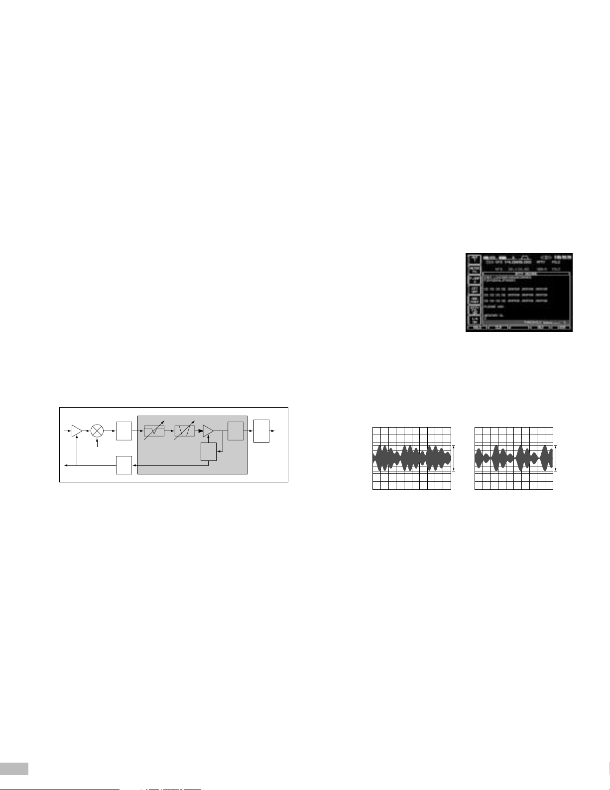
■ Demodulator/decoder for RTTY
This transceiver is equipped with a demodulator and a decoder for
BAUDOT RTTY as a standard feature. On-air station calls may be
recognized instantaneously by reading the received RTTY message
directly on the IC-756PROII’s LCD – no personal computer or
external components are required. The transceiver is fitted with an
on-screen tuning indicator that allows the RTTY to be fine tuned with
ease. A DSP based twin-peak audio
filter further improves the S/N ratio.
This filter will reduce interference that
appears between each tone (mark
and space), which cannot be removed
by conventional analog filters. This
twin-peak audio filter works to capture
noise-level signals accurately and to
significantly reduce the generation of
noise distortion.
■ New-generation speech compressor
The DSP based speech compressor enhances the readability of your
transmitted signal at a receiving station without any distortion, even
when the compression is set to a high level. The gradation of voice
processing is extremely close to the original sound. This assures
superior sound quality at all compression levels.
■ Microphone equalizer (enables 121 different settings)
The IC-756PROII is equipped with a microphone equalizer that makes it
possible to set the frequency characteristics of the transmitted signal in
11 different stages for both the high-tone range and the low-tone range.
Considering all permutations, this provides for a total of 121 different
settings. With this flexibility of DSP based waveform shaping, it is
possible to adjust transmit audio quality depending on the application.
For example, it is possible to set the dynamic sound quality for “Pileup”
or to set pleasant sound for “Ragchewing”.
■ Variable level type noise reduction
The 32-bit floating point DSP has excellent calculation performance,
which processes complex and sophisticated algorithms. This allows
the DSP to attenuate noise without delay and extracts noise-level
signals. It is possible to vary the suppression level in 16 stages.
■ CW keying waveform shaping function
DSP controls the rise and fall of the CW transmit waveform. The
result is a proper CW waveform. The rise/fall timing is selectable to 4
stages of 2ms, 4ms, 6ms and 8ms. This makes it possible to set a
“Soft” or “Hard” CW signal, depending on your preference.
455
kHz36kHz
3Lo
Manual
NOTCHIFFilter
DET
AGC
AGC
DSP
DAC
DAC
ADC
AF
100W
2.5ms/Div2.5ms/Div
100W
Speech compressor on Speech compressor off
RTTY reception screen
2. Features
Page 5
5
Enhanced functions
■ Advanced receive functions
The RF stage’s front-end receive mixer is designed in a 4-element
configuration. In the IC-756PROII, this configuration is used in the
BPF stage at the RF top. Each element is examined to tune the
circuit after RF stage to mixer, which makes it possible to enhance
the receive performance. This significantly reduces 3rd and other
order distortion and provides a wide dynamic range. This means the
IC-756PROII will accurately capture weak signals that analog type
radios cannot hear, even in low bands with high noise levels.
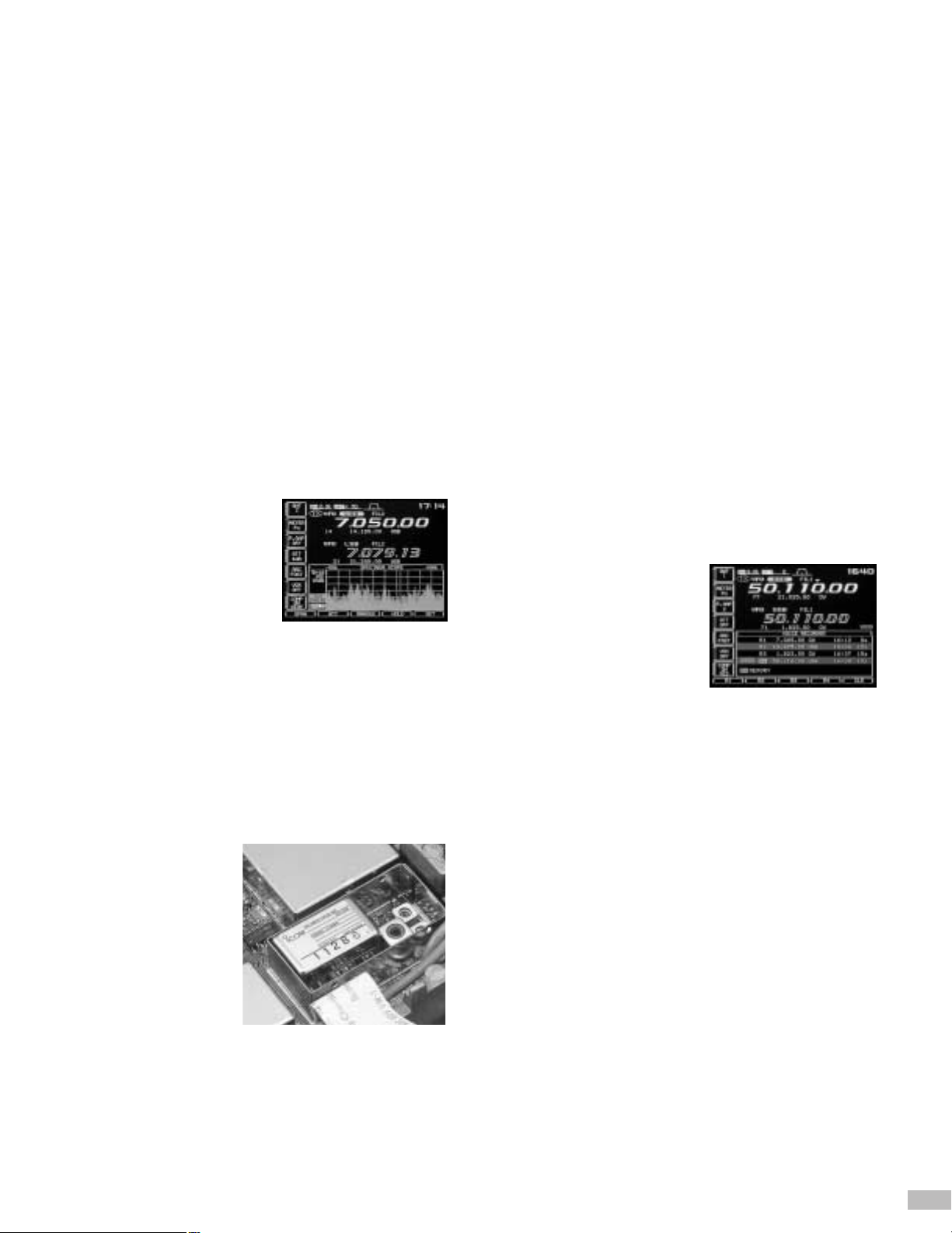
■ Real-time spectrum scope
A real-time spectrum scope is recognized as indispensable for DX
hunting. The IC-756PROII’s spectrum scope uses two colors to
display all RF signal activity within a user-selectable bandwidth. One
color indicates real-time RF signal activity, while the other color
provides peak hold indication. The spectrum scope may be used for
sophisticated applications such as identifying the band conditions,
quick discovery of stations, and confirmation of interval or call-back
frequency. Additionally, you may monitor normal band conditions,
while you display sub readout or transmit markers. In case of highband noise, the IC-756PROII is equipped with an attenuator
(10/20/30dB) dedicated to the spectrum scope, which allows a
reduction of total signal level at the band scope without affecting the
received signal.
■ Exceptionally clear SSB transmit signal
Using Icom’s advanced digital PSN modulation, the IC-756PROII
emits high-quality signals, which makes its transmitter suitable for
use as the exciter of a linear amplifier. Unwanted sidebands and
carrier leaks are almost completely eliminated. Further, the
transmitter employs a wide band power amplifier that incorporates
highly reliable bipolar transistors (2SC5125 × 2). The linearity and
IMD characteristics achieve superior signal quality never before seen
in any amateur redio transceiver. This makes it possible to transmit
RF signals with significantly reduced distortion.
■ Built-in high-stability reference crystall oscillator
The IC-756PROII’s transceiver
exhibits excellent frequency
stability of < 0.5ppm. This
assures stable communication
even for RTTY and SSTV
modes for which particularly
high frequency stability is
required.
The best in operating convenience and features
■ Dual-watch
Dual-watch enables simultaneous two-frequency receive in the same
band, providing identical band and filter configurations in both receive
systems. This makes it possible to receive two signals simultaneously
as if two separate receivers are being used. This greatly enhances
split frequency operation; enjoy enhanced DX-operation by searching
for pickup frequencies while watching the transmit frequency of a DX
station experiencing pile-up. Or have a QSO while simultaneously
monitoring a DX net.
■ Triple band stacking register
With the push of a band button, get quick memory recall of three
preferred operating settings (including antenna port) per band. Band
or mode hopping has never been easier. It’s the ultimate in multimode flexibility.
■ Digital Voice Recorder (DVR)
The DVR feature is an indispensable function for DX hunting and
contests. The IC-756PROII is equipped with a DVR with 4 channels
for transmit and 4 channels for receive, for a total of 8 channels. High
quality digital mapping of the transmitted or received analog signal
provides high quality audio reproduction, resulting in a natural
sounding voice without any noticeable degradation. It is also possible
to use these 4 communication channels by allotting them freely with a
total recording time of 90 seconds. Each of the 4 channels for receive
has a recording time of 15 seconds, or 60 seconds total. Press the
key once in any TFT display mode and it becomes possible to not
only record or reproduce voice but also to record for up to 30 minutes
continuously. The receive audio may
be reproduced for the most recent 15
seconds back to an interruption in
recording. By constructing the
simplified control unit (page 26) and
connecting it to the microphone
connector, digital voice recorder
function may also be operated.
■ Full-scale electronic keyer
Plug a CW, iambic paddle into the electronic keyer jack on the front
panel. Especially handy during long hours of operation, it is possible
to set the CW speed between 7 and 56WPM. The discriminating
operator may also set the dot/dash keying ratio (2.8:1 to 4.5:1) and
polarity, depending on preference. The keyer may also be set for
either right or left hand use. For the CW operator who prefers not to
use the IC-756PROII’s built-in electronic keyer, an ordinary key jack
is available on the rear panel, for bug or straight key and is fully
compatible with external keyers or PC keying.
■ Multi-function memory keyer
Enhance your contest operations. The IC-756PROII is fully equipped
with a convenient memory keyer, offering features such as memory
content editing function, auto-repeat function, serial contest number
automatic count-up function, contest number abbreviating function, and
more. These features will reduce effort when repeating a formatted
contents for calling CQ, continuous transmission of call sign, or contests.
Since it is possible to confirm the contents of memory on the display,
transmission mistakes are eliminated. Construct the simplified control
unit (page 26) and connect it to the microphone connector to enhance
operation of these memory keyer functions.
Real-time spectrum scope screen
DVR key
High-stability reference crystal oscillation unit
Page 6

6
■ Quick split function
When the split button is pressed and held, the frequency of the subVFO is adjusted to the frequency in the main VFO. Using the split
function, it is also possible to control the following:
1. Vary the transmit frequency via the main dial.
2. Direct entry of the designated frequency.
3. Direct entry of the shift frequency.
You are now ready to “bag the DX” while other operators are still
tuning up.
■ Preamplifier and attenuator
The IC-756PROII incorporates two types of receive preamplifiers:
Preamplifier 1 (10dB) emphasizes modulation across all bands, and
preamplifier 2 (16dB) emphasizes sensitivity especially for high
bands. The attenuator is selectable in three stages, 6, 12 and 18dB.
When there is a strong signal from a local commercial station it
becomes possible to control the generation of distortion at the RF
stage of the receiver. It is also possible to retain the preamplifier and
attenuator settings for each band.
■ Variable noise blanker
The transceiver uses a new noise blanker design that provides
significant reduction of pulse-type noise. The noise blanker also
greatly enhances weak signal copy, allowing the operator to change
the sensitivity in 100 stages in accordance with the noise level
without distorting the target signal.
■ Frequency shift function for change from/to SSB to/from CW
A frequency shift function automatically adjusts the CW carrier point
when selecting from SSB mode, or vice versa. You may select “Shift
function off” whereby the frequency remains the same (by moving the
carrier point), or “Shift function on” in which the frequency is shifted
without moving the carrier point. Using CW-R mode it is possible to
set the carrier point to USB.
Enhanced TFT color display
■ High visibility
A high visibility 5-inch TFT color display has been integrated into the
IC-756PROII to provide ease of use and clear indication of the radio’s
many features. Various function settings such as frequency, memory
frequency, comment, filter setting status, RTTY tuning indicator, and
more are displayed in the upper portion of the display, The lower
portion of the display gives voice memory, characters of received
RTTY, and the real-time spectrum scope information. The display
color may be selected from 8 types, from vivid color to muted grays. 7
different font types may also be selected. These settings may be
made in any combination – customize your display to best suit your
personality or favored operating set-up.
■ Memory channel/memory list
The transceiver is equipped with 99 regular memory channels and 2
scan edges, totaling 101 channels. It is possible to enter text of up to
10 characters in each memory channel. It is also possible to display a
list of up to 13 memories at a time.
■ Simplified set mode
The IC-756PROII has a list display that allows the status of each set
mode item to be seen at a glance. Each function is divided into 4
setting groups and multiple items are listed or displayed to allow
quick access to the desired item. This allows the many functions of
the radio to be used with ease.
■
Digital meter simultaneously displays 4 transmit level indicators
With the digital meter (including peak-hold), it is possible to confirm
the output power, ALC, SWR, and COMP, all at the same time while
transmitting. The signal strength is also displayed while receiving.
Enhanced functions
■ Antenna system
· High-speed built-in auto antenna tuner covering up to the 50MHz
band
· 2-piece antenna terminal (incorporated with auto antenna selector)
· Dedicated receive antenna connector
■ Receive system
· General coverage receive (30kHz to 60MHz)
· Control of RF gain and squelch with one knob
■ Transmit system
· IF Monitor function allows the transmissions of your station to be
listened to locally
· Built-in 50 frequencies of tone encoder/decoder
· VOX function allows the automatic selection of transmit and receive
for “hands free” operation
· All-mode power control function
■ CW system
· CW pitch control function allows the CW receive tone to be set to a
desired frequency (300 to 900Hz continuously)
· Double key jack allows 2 types of keys to be connected
simultaneously
· Full break-in function allows receive during a break while keying
■ Operation system
· 5-channel memo pad saves frequency and mode
(It is also possible to change the 5-channel memo pad to a 10channel type.)
· RIT and TX variable up to ± 9.999kHz
· 1Hz pitch tuning
· Optional frequency speech allows the S-meter level to be
announced
· High visibility needle type white-tone analog meter
· Various scanning functions (program, memory, select memory, F)
· Auto Tuning Step
· Dial-lock
· Split frequency lock
· Torque adjustment mechanism for main dial
· Band edge beep function
· CI-V terminal allows control from a personal computer
· Clock/timer function
· AH-4 control circuit
Page 7
7
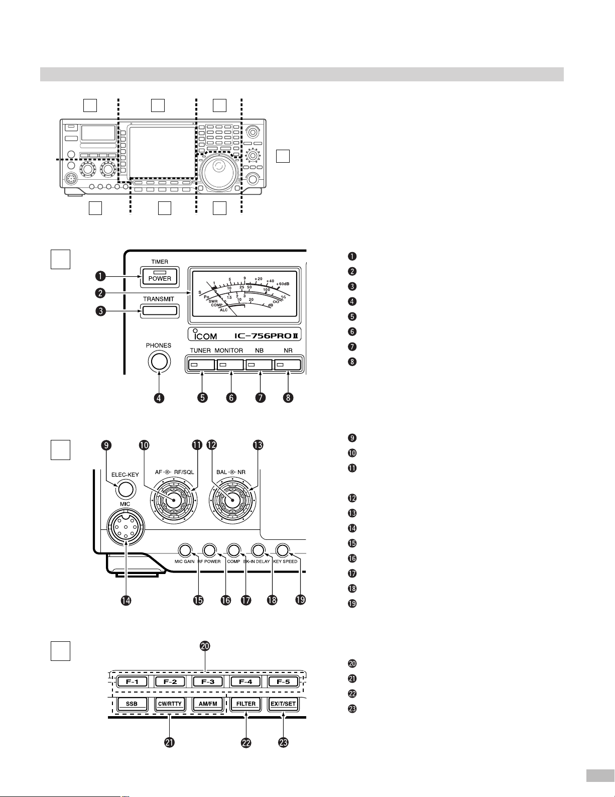
3. Front and rear panel
3-1 Front panel
A
A
D E
B C F
G
B
C
POWER SWITCH [POWER TIMER]
S/RF METER
TRANSMIT SWITCH [TRANSMIT]
HEADPHONE JACK [PHONES]
ANTENNA TUNER SWITCH [TUNER]
MONITOR SWITCH [MONITOR]
NOISE BLANKER SWITCH [NB]
NOISE REDUCTION SWITCH [NR]
ELECTRONIC KEYER JACK [ELEC-KEY]
AF CONTROL [AF]
RF GAIN CONTROL/SQUELCH CONTROL
[RF/SQL]
BALANCE CONTROL [BAL]
NOISE REDUCTION LEVEL CONTROL [NR]
MICROPHONE CONNECTOR [MIC]
MIC GAIN CONTROL [MIC GAIN]
RF POWER CONTROL [RF POWER]
COMPRESSION LEVEL CONTROL [COMP]
SEMI BREAK-IN DELAY CONTROL [BK-IN DELAY]
ELECTRONIC CW KEYER SPEED CONTROL
[KEY SPEED]
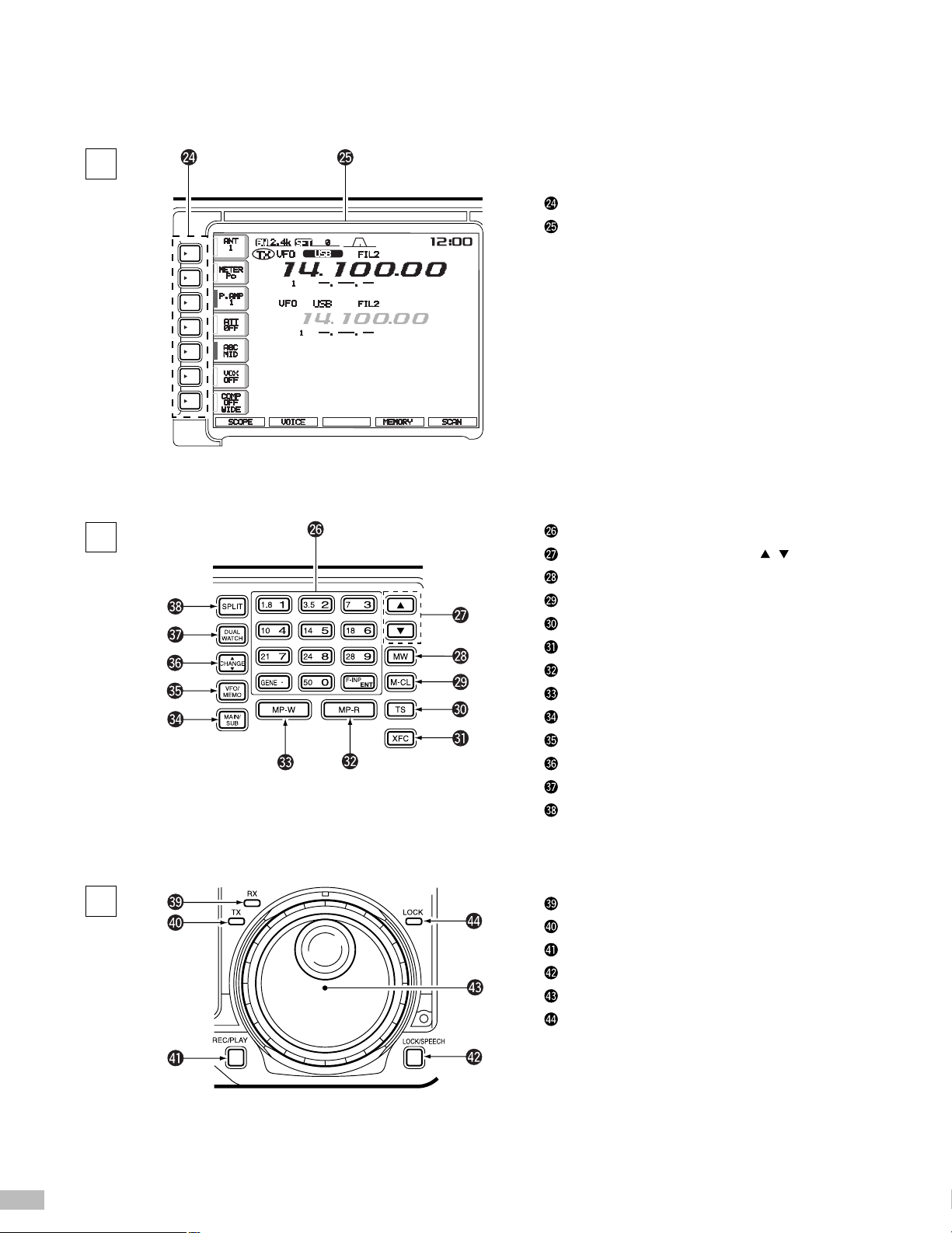
LCD FUNCTION SWITCHES [F1]-[F5]
MODE SWITCHES
FILTER SWITCH [FILTER]
EXIT/SET SWITCH [EXIT/SET]
Page 8
8
D
E
F
MULTI-FUNCTION SWITCH GUIDE
LCD FUNCTION DISPLAY
KEYPAD
MEMORY UP/DOWN SWITCHES [ ][ ]
MEMORY WRITE SWITCH [MW]
MEMORY CLEAR SWITCH [M-CL]
QUICK TUNING SWITCH [TS]
TRANSMIT FREQUENCY CHECK SWITCH [XFC]
MEMO PAD-READ SWITCH [MP-R]
MEMO PAD-WRITE SWITCH [MP-W]
MAIN/SUB CHANGE SWITCH [CHANGE]
VFO/MEMORY SWITCH [VFO/MEMO]
MAIN/SUB CHANGE SWITCH [CHANGE]
DUALWATCH SWITCH [DUALWATCH]
SPLIT SWITCH [SPLIT]
RECEIVE INDICATOR [RX]
TRANSMIT INDICATOR [TX]
REC/PLAY SWITCH [REC/PLAY]
LOCK/SPEECH SWITCH [LOCK/SPEECH]
TUNING DIAL
LOCK INDICATOR [LOCK]
Page 9
9
G
PASSBAND TUNING CONTROLS [TWIN PBT]
PBT CLEAR SWITCH [PBT CLR]
NOTCH SWITCH [NOTCH]
MANUAL NOTCH FILTER CONTROL [NOTCH]
CW PITCH CONTROL [CW PITCH]
TX SWITCH [ TX]
RIT SWITCH [RIT]
RIT/ TX CONTROL [RIT/ TX]
CLEAR SWITCH [CLEAR]
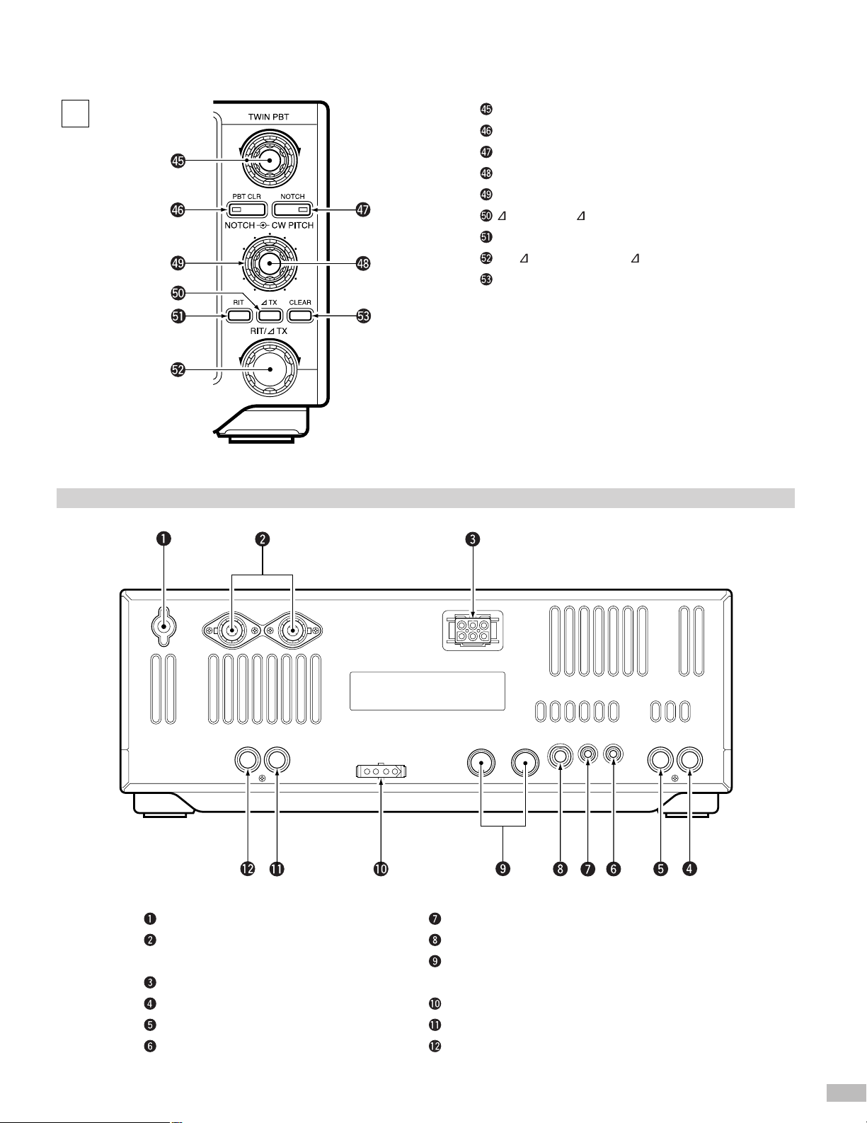
3-2 Rear panel
CI-V REMOTE CONTROL JACK [REMOTE]
STRAIGHT KEY JACK [KEY]
ACCESSORY SOCKET 1 [ACC (1)]/
ACCESSORY SOCKET 2 [ACC (2)]
TUNER CONTROL SOCKET [TUNER]
RECEIVE ANTENNA CONNECTOR [RX ANT]
TRANSVERTER JACK [XVERT]
GROUND TERMINAL
ANTENNA CONNECTOR 1 [ANT 1]/
ANTENNA CONNECTOR 2 [ANT 2]
DC POWER SOCKET [DC 13.8V]
SEND CONTROL JACK [SEND]
ALC INPUT JACK [ALC]
EXTERNAL SPEAKER JACK [EXT SP]
ANT1ANT2
AC C (2)AC C (1)
Page 10
10
4. What is DSP in radio communication?
The term DSP stands for “digital signal processor”. When DSP is
used in a communication unit, the electrical signal processes
(amplification, filtering mixer, modulation, demodulation, etc.) are
handled by the DSP. Such signal processing, using numerical
calculations, is called “digital signal processing”.
Digital signal processing assures the same results every time
providing for the characteristics defined in the design phase. When
digital signal processing is utilized, it is not necessary to take the
adjustment deviations of the conventional analog circuit into
consideration. These deviations are caused by variations in
component characteristics, temperature change, or deterioration over
time. It is also possible to perform complicated processing tasks such
as Fourier transformation, adaptive control, special function
processing (*1), and more. Such complicated processing tasks are
very difficult and costly for a conventional analog circuit.
*1Special function processing: Trigonometric function, inverse function of trigonometric
function, square root, logarithmic function, exponential function, etc.
Digital signal processing is also widely used in fields other than radio
communication units, such as:
· Modems for telephone circuits
· Surround-sound effects (stereo sets, stereo components)
· Echo canceller (telephone)
· Voice compression/coding (cellular phones)
It is possible for a computer CPU to execute digital signal processing.
However, a DSP differs from a CPU in that it has the dedicated
hardware construction required for the effective execution of digital
signal processing. Basically the unit has a multiplication/addition
circuit widely used for DSP to execute the combination of
multiplications and additions in one clock, and with an internal data
bus of more than two circuits, to fetch two data items required for
calculation at the same time. It also has a loop processing function to
execute repeated calculations with high efficiency and a data address
creation function to transmit signal data effectively, which are
assigned to consecutive addresses. These functions are incorporated
as dedicated hardware.
Because their performance has developed quickly, the CPUs
currently used for computers can execute digital signal processing. A
CPU with a high clock frequency may be superior in calculation
performance to a low-end DSP chip. When it is compared with a CPU
of equivalent performance, a DSP with hardware specialized to digital
signal processing has the following advantages:
· Low clock frequency
· Low integrity (reduced logic scale)
· Low power consumption (Low
heat energy generated)
· Low cost
When various judgment functions
are required, or when different
calculations are repeated each time,
a DSP is not suitable. The CPU is
then more suitable for such
processing.
Background to development of the first-generation
IC-756PRO
From the early stages of research into DSP transceivers Icom has
been on the forefront of shifting IF filter design from analog to digital
type filters. To put the digital IF filter to practical use it was necessary
to incorporate the digital IF filter into the AGC loop. It was also
necessary to provide AGC processing using the DSP. To achieve this
there remained a lot of technical problems to be resolved.
In the initial stage of research, it was not possible to complete the
DSP, A/D, and D/A devices in a radio unit at a practical cost, as
shortage in device capacity was a significant factor. Icom conducted
research into digital PSN modulation, noise reduction, automatic
notch, and audio peak filter, while also proceeding with research into
digital IF filter processing and digital AGC processing. This research
includes the ultra-narrow filter for CW that allows the advantages of
DSP to be fully utilized for commercialization of a DSP transceiver.
As the first devices were developed with improved capacity, Icom
started full-scale research into integrating the digital IF filter
processing (*2) and digital AGC processing in practical applications.
*2Advantages of digital IF filter processing:
Since a digital IF filter is free from deterioration due to passband width deviations,
temperature changes, change in mechanical strength, etc., the changes seen in an
analog filter will not occur. It will not deteriorate through years of use and will provide
excellent ripple characteristics that are not possible with analog filters.
When the DSP filter is processed at the AF stage, the demodulated
AF signal is filtered after this. This filter type will function effectively
when the level of the interfering signal is equal to or less than that of
the desired signal. However, when the level of the interfering signal
increases, the AGC activates reducing the level of the desired signal
causing it not to be heard (AGC blocking phenomenon). This
phenomenon is caused by filtering taking place outside the AGC
loop. Even if filtering is executed at the IF stage before demodulation,
it is not possible to avoid this blocking phenomenon when the digital
filter is not incorporated in the AGC loop. Therefore, it is necessary to
execute both IF filter processing and AGC processing using the DSP
to prevent the AGC blocking phenomenon.
To realize a digital AGC, it is necessary to obtain the adjustment
range for AGC gain internally in the DSP (*3), and to input both the
desired signal and the interference signal into the A/D converter
without them distorting (*4). For these reasons, Icom decided on a
dynamic range for the A/D converter of at least 110dB, and
approximately 120dB when the margin is taken into consideration.
*3To control the AGC attack response properly, it is necessary to adjust the gain even after
the completion of IF filter processing. If the adjustment range of gain within the DSP is set
to 60dB, it is necessary to obtain a wider dynamic range, as the noise floor is raised 60dB
under full-gain conditions where AGC is not applied.
*
4
If the signal is distorted before entering the A/D converter, a distortion component may be
mixed in the band. If it is mixed in the band, it is extremely difficult to remove it by post
processing.
The DSP in the IC-756PRO/756PROII employs a 24-bit A/D
converter. The logical value of the dynamic range of a 24-bit A/D
converter is 144dB, however the actual value of the analog
performance is smaller than this and performance may differ
considerably, depending on the type of A/D converter used.
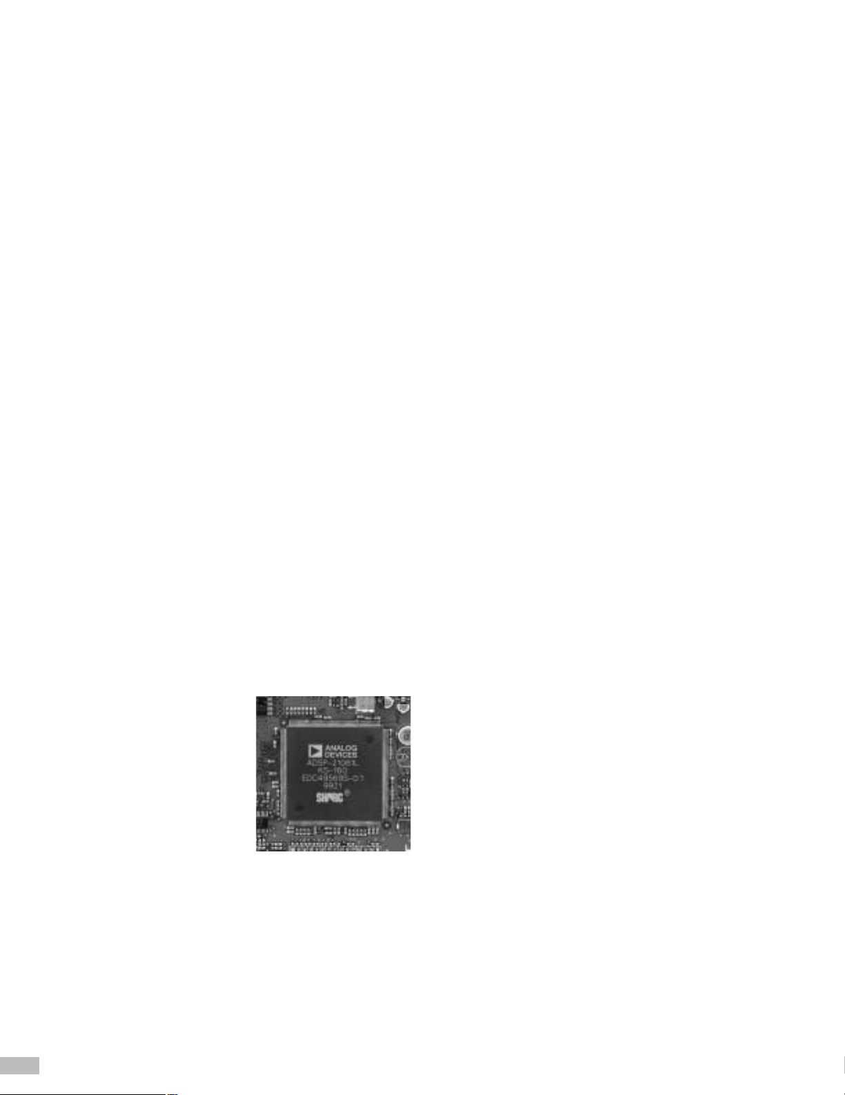
DSP chip
Page 11
11
The A/D converter used for the IC-756PROII is a super-high
performance A/D converter that is also used in digital mixers for
recording studios and provides an actual analog performance value
of 120dB. To bring this performance to an optimum level it is
necessary to execute calibration for 10 seconds after powering on.
The wait time when IC-756PROII is started is allotted to the
calibration operation.
To execute the processing of data sampled by the 24-bit A/D
converter it is necessary to obtain 24-bit calculation accuracy. Since
the dynamic range is decreased substantially due to the scaling
operation (*5) for the accumulation of calculation errors or digital filter
processing, Icom felt the 24-bit fixed decimal point DSP would
provide insufficient calculation accuracy.
*5Scaling
For digital filter processing, a frequency which causes the gain to increase may exist at
the intermediate stage of processing even if the filter used provides a passband gain of
0dB. For a fixed decimal point, DSP the calculation is executed with the gain decreased
in advance so as not to allow an overflow to occur due to a signal of that frequency.
This gain adjustment operation is called “scaling”.
Since the level of scaling required is also increased to provide an IF
filter with a sharp shape factor the calculation accuracy is liable to be
decreased, even if double-precision (32-bit fixed decimal point)
calculation is executed when using a high-speed 16-bit DSP. To
provide both the digital IF filter processing and digital AGC
processing using DSP, Icom determined it was necessary to use a
32-bit floating point DSP.
For a 32-bit floating point DSP, the numerical data within the DSP is
adjusted automatically according to the size of the numerical value.
Consequently, errors generated due to calculation are extremely
limited and the influence of calculation errors is almost negligible.
Because it is not necessary to consider the overflow during
calculation, the dynamic range will not be decreased due to the
scaling operation.
The 32-bit floating point DSP and 24-bit A/D-D/A converter use a
signal processing algorithm (newly developed to demonstrate its
performance) in combination for the reasons above, which make it
possible to provide highly accurate digital IF filter processing and
digital AGC processing. These new functions (FM demodulation, AM
modulation/demodulation, RTTY modulator, etc.) were incorporated
in the IC-756PRO to make it an IF DSP radio.
Two Dynamic ranges
Dynamic range as RF performance
“Dynamic range” from the viewpoint of RF performance indicates to
what extent the distortion component (generated due to the
frequency of a signal) can be heard at the receive frequency when a
frequency component different from two receive frequencies is input.
“Dynamic range” generally means the value by 3rd order distortion
component.
If the receive frequency is substituted for “fRX”, the input frequency for
“f1” and the input frequency for “f2” respectively, the following
relationship is established for 3rd order distortion component.
f1 × 2 ± f2 = fRX, or
f1 ±f2 × 2 = fRX
If there are inputs of 14.2MHz and 14.3MHz while 14.1MHz is being
received, the distortion component is heard at 14.1MHz. The relative
value of the input level when the signal can be heard at 14.1MHz and
the level of the signal received at the essential receive frequency is
called the “dynamic range”.
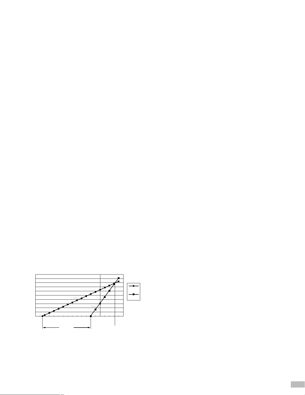
Figure 1 shows an example in which the following are plotted on the
same axis.
· Input/output characteristics at receive frequency, or the
characteristic data (a) for a case when the receive frequency
component input from the ANT is detected and output as a low
frequency signal
· Input level of frequency component (generating 3rd order distortion
from the receive frequency) and level (b) at which the distortion can
be heard at the receive frequency.
The difference in level at which (a) and (b) above can be heard is
the dynamic range.
The level at intersecting point between (a) and (b) above is called
IP3 (3rd order intercept point).
If these numerical values are large, it can be said that signal
processing is executed without distortion. When the numerical values
are small, a frequency component that does not exist in the essential
receive frequency is heard and distortion will be generated.
Dynamic range for A/D converter
Consider the dynamic range (used as an index for the performance of
an A/D converter) as the ratio between maximum value and minimum
value to be treated by the A/D converter. If the maximum resolution
for one bit is “Vmax” in the case of a 16-bit A/D converter, the
following is given:
Vmax ÷ 216= Vmax ÷ 65536
In other words, the change in level for one bit is 1/65536 of Vmax.
This value seems to be an extremely small value, in decibels it will be
as follows:
20log (1/65536) = –96.33dB
This means that an S/N ratio of over 96dB is never allowed for
transmit. The minimum resolution of signal the A/D converter can
treat is affected by its specifications, which are 24 bits and 144dB
logical value. Some may say that a transceiver is not a high-grade
audio system and therefore does not require a specification of 144dB,
or that a specification of 96dB is sufficient; however this value is not
an over specification. If there is no AGC in the DSP and the input
level of the A/D converter is properly controlled by the analog circuit
AGC, the specification of 96dB will be sufficient (the IC-775DSP uses
this system). When the A/D converter is in the AGC loop, the input
level of the A/D converter may fluctuate significantly. For this reason,
the gain control by AGC within DSP requires at least the dynamic
range of the A/D converter.
Fig. 1
–140
–130
–120
–110
–100
–90
–80
–70
–60
–50
–40
–30
–20
–10
0
20
40
60
80
100
120
140
160
180
200
010203040
50
[dBm]
[dB]
Output
3rdIMD
Dynamic IP3
(a)
(b)
Page 12
12
5. Circuit description
5-1 Digital IF filter
For IC-756PROII the transmit/receive passband width in all modes is
determined by the digital IF filter using DSP. A filter of this type
provides an ideal shape factor that cannot be achieved by an analog
filter. If an attempt is made to increase the shape factor and band
ripple characteristics of an analog filter, it is necessary to increase the
number of crystal components (or ceramic elements), which may
result in physical restrictions. A digital IF filter using DSP assures the
desired characteristics by overlaying multiple filters. This is governed
only by the processing volume of the software and it is possible to
overlay such filters with any number of stages.
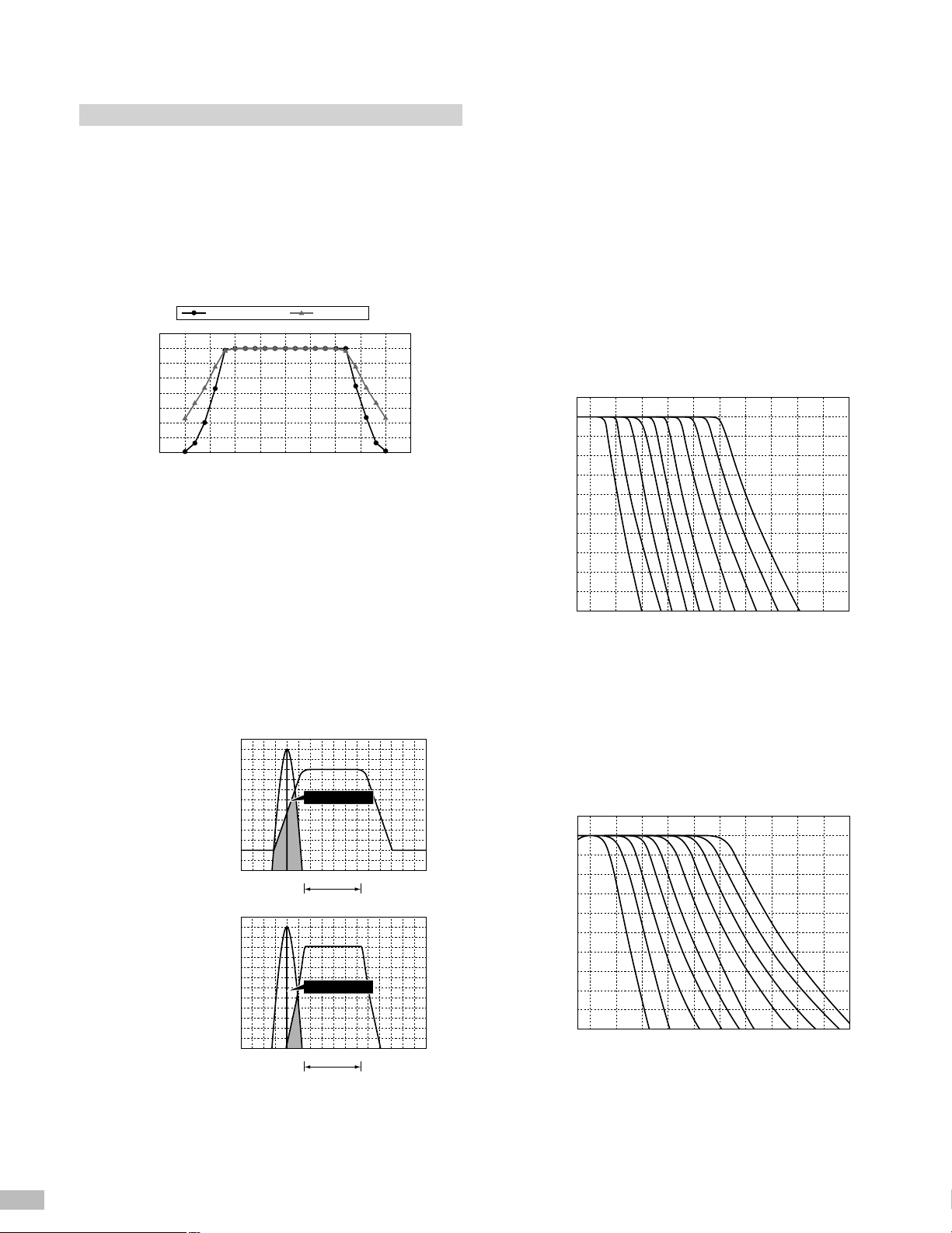
The diagram shows a graph of receive selectivity when the IC756PROII is set to the SSB BW mode of 2.4kHz as well as the
selectivity characteristic of each Collins 10-pole mechanical filter. The
digital IF filter of the IC-756PROII is of a design equivalent to a 14pole filter. The filter serves to cut the undesired adjacent signals
sharply under any circumstances using the superior shape factor
(sharp/soft) and 51 types of variable passband width provided by IF
stage processing using the DSP. When viewing a received CW signal
the difference between the cut-off performance of this filter and that
of an analog IF filter is evident.
In a transceiver equipped with a conventional analog IF filter the beat
frequency of an adjacent signal is present when the CW signal is
received resulting in interference. The beat frequency is contained in
the skirt of the filter even if it is out of the set band range. (Fig. 1.1)
When using a digital IF filter the beat frequency of an unwanted
adjacent signal moves out of the filter passband width, which will not
cause interference. (Fig. 1.2) This is the greatest difference between
an analog IF filter and a digital IF filter. During “pile-ups”, such as
those that occur in DX’peditions, contests, etc., it is possible to make
a proper selection suitable to the application by selecting the broad
filter shape (SOFT).
5-1-1 CW sharp filter
The digital IF filter offers an ideal shape factor which has never been
available with conventional analog filters. It enables a greater ability
to receive weak stations that may lie behind radio interference. This
is the filter shape that Icom would suggest to the DX hunter due to its
superior cut-off performance. The cut-off performance is of a level to
actually extend the CW band as explained above.
5-1-2 CW soft filter
The skirt characteristics of the soft filter are broadened so that the
listening level of the filtered signal is the same level as that of a
conventional analog filter. When using the radio for DX’pedition the
filter is recommended for “pile-up” operation and is most suitable for
the CW DX’peditioner and CW contestant.
Response
–70
–2000
–1500
–1000
–500
0
500
1000
1500
2000
–60
–50
–40
–30
–20
–10
–0
10
[dB]
Input frequency
[Hz]
756PROII SSB COLINS10
Fig. 1.1
Conventional
analog filter
The signal out of setting
band is also heard as
CW reception sound.
Beat frequency
0
10
20
30
–10
–20
–30
–40
–50
–60
–70
–80
–90
–100
–600–800 –400 –200
500Hz setting
0 200 400 600 800
[dB]
[Hz]
30
Digital filter of
IC-756PROII
The signal out of setting
band is not heard as
CW reception sound.
Beat frequency
10
20
–10
–20
–30
–40
–50
–60
–70
–80
–90
–100
–600–800 –400 –200
500Hz setting
0 200 400 600 800
[dB]
[Hz]
Fig. 1.2
–100
–90
–80
–70
–60
–50
–40
–30
–20
–10
0
10
[dB]
500450400350300250200150100500
[Hz]
CW Filter (BW 50/100/150/200/250/300/350/400/450/500Hz)
CW sharp filter characteristic
–100
–90
–80
–70
–60
–50
–40
–30
–20
–10
0
10
500450400350300250200150100500
[Hz]
CW Filter (BW 50/100/150/200/250/300/350/400/450/500Hz)
[dB]
CW soft filter characteristics
Page 13

5-1-3 SSB sharp filter
This filter creates an ideal shape factor and in-band flatness, and
makes it possible to cut out-of-band signals while reproducing the inband signal, without deteriorating sound quality. This filter shape is
most suited for situations which emphasize ragchewing and receive
sound quality.
5-1-4 SSB soft filter
The soft filter shoulder is rounded to provide a receive sound
approximating an analog filter. The noise is reduced for high-pass
and low-pass to improve the S/N ratio for the desired signal. This
function will demonstrate its effect when the signal closest to the
noise level is picked up in the 50MHz band. Since the desired skirt
characteristics are maintained it assures superior filtering
performance.
5-1-5 Other digital filters
FIL1
FIL2
FIL3
FIL1
FIL2
FIL3
FIL1
FIL2
FIL3
FIL1
FIL2
FIL3
FIL1
FIL2
FIL3
3.0kHz
2.4kHz
1.8kHz
1.2kHz
500Hz
250Hz
2.4kHz
500Hz
250Hz
9.0kHz
6.0kHz
3.0kHz
15kHz
10kHz
7.0kHz
50–500Hz (50Hz) /
600–3.6kHz (100Hz)
50–500Hz (50Hz) /
600–3.6kHz (100Hz)
50–500Hz (50Hz) /
600–2.7kHz (100Hz)
–
–
13
SSB Sharp Filter
–160
–140
–120
–100
–80
–60
–40
–20
0
20
[dB]
–4000 –3000 –2000 –1000
0 1000 2000 3000 4000 5000 6000
[Hz]
SSB Filter (BW 2.4kHz)
AM Filter Characteristic
–10
–120
–100
–80
–60
–40
–20
0
20
[dB]
–8 –6 –4 –20246810
[kHz]
AM Filter (BW 3/6/9kHz)
FM Filter Characteristic
–120
–100
–80
–60
–40
–20
0
[dB]
0–5–10 5 10
[kHz]
FM Filter (BW 7/10/15kHz)
–160
–140
–120
–100
–80
–60
–40
–20
0
20
[dB]
–4000 –3000 –2000 –1000
0 1000 2000 3000 4000 5000 6000
[Hz]
SSB Filter (BW 2.4kHz)
SSB Soft Filter
RTTY filter characteristics
–100
–90
–80
–70
–60
–50
–40
–30
–20
–10
0
10
[dB]
–100 0 100 200 300 400 500 600 700 800 900 1000
[Hz]
RTTY Filter (BW 250/300/350/500/1000Hz)
Application mode
SSB
SSB•D
CW
RTTY
AM
FM
FILTER
Standard values
Setting range (step width)
Digital IF filter transmission band (51 types)
Page 14

14
5-2 Digital functions
5-2-1 Noise reduction, automatic notch
An adaptive filter made up of an FIR filter and LMS algorithm as
shown in Fig. 2 is used to provide the basic configurations of noise
reduction and automatic notch. This adaptive filter (*5) separates the
target signal and noise, the correlation of separation parameters, and
controls the coefficient of the FIR filter with the LMS adaptive
algorithm to minimize the error between the output of the FIR filter
and the reference signal.
*5Adaptive filter
This type of filter is called an “adaptive filter” since the filter characteristics are changed by
adapting to the characteristics of the input signal.
5-2-2 Noise reduction
The adaptive filter allows the target signal to pass while the noise
component (random signal) is attenuated. The voice signal has a
high short-time correlation and a low long-time correlation. (For
discrimination the signal correlation is called “short-time” or “longtime” for convenience, however it is a difference of only several
hundreds microseconds.) If the correlation separation parameters are
set to allow short-time correlation to be detectable, the voice signal is
detected as a low correlation component, and the noise as a high
correlation component. In this case the voice component must pass
as it is, and only the noise component is attenuated. The noise
reduction effect is random at the head of a word (the moment when
speech begins) and at points where intonation changes significantly.
If the noise reduction effect is increased too much, the voice
component may be attenuated together with the noise as described
above. In this case it may decrease clarity, even if the S/N ratio is
improved.
The transceiver is designed with the flexibility to set the noise
reduction level accurately (16 stages) in order to meet all
circumstances. This makes it possible to adjust the balance between
the S/N ratio and clarity quickly.
5-2-3 Automatic notch
If the correlation separation parameters are so set to allow long-time
correlation to be detectable, the voice signal is detected as a low
correlation component, and only the tone signal is detected as a high
correlation component. If the correlation separation parameters are
set to allow long-time correlation to be detectable the voice signal is
detected as a low correlation component, and only the tone signal is
detected as a high correlation component. Since this setting makes it
possible to separate the tone signal component from the voice
component the output from the adaptive filter will be only the tone
signal. Since the phase and amplitude of the tone signal from this
adaptive filter become the same as those of the input signal, the
output of the error signal shown in Fig. 2 makes it possible to obtain a
voice signal from which the tone signal is removed. In other words,
this adaptive filter setting will operate as an automatic notch to
remove beat interference such as CW and RTTY signals, which may
interfere with SSB. Automatic notch makes it possible to detect and
remove interference correctly even when more than two tones occur.
As the tone frequency changes the interference is followed and
removed automatically. Since the characteristics are adjusted to
minimize the influence upon a voice, it can be used in SSB mode
without any sense of incongruity even if automatic notch is turned on
all the time.
+
–
Adaptive
algorithm
FIR filter
Coefficient
control
Reference signal
Adaptive filter output
Error signal
Correlation
separation
parameters
Input signal
∑
Fig. 2
5-3 PSN modulation
The IC-756PROII adopts a digital PSN modulation system for SSB
modulation processing to provide superior band characteristics and a
high transmission S/N ratio. This means that unwanted sidebands
and carrier leaks are almost completely eliminated. This section
explains the principle of operation while comparing the PSN type
SSB modulator with the analog filter type SSB modulator used in
conventional analog transceivers.
5-3-1 Analog filter type SSB demodulator
The configuration of analog filter type SSB modulator is shown in Fig. 3.
If the tone signal of frequency (f1) is presented to a microphone, two
spectra (f2–f1 and f2+f1) are generated against the mixer output as
shown in Fig. 4.
This mixer output passes through the IF filter, passing only the
necessary band. Its unwanted sideband is attenuated, which assures
a modulated SSB signal. (Fig. 5)
Balanced mixer
Modulation carrier
Modulated output
MIC
f
1
f2
IF filter
Fig. 3
Frequency
(f
2–f1)f2 (f2+f1)
Fig. 4 Mixer output spectrum
Frequency
Passing
characteristics
of IF filter
(f
2–f1)f2 (f2+f1)
Fig. 5 SSB demodulated wave
Page 15

15
Since the performance limits of the IF filter become the performance
limits of the modulator in an analog filter type SSB modulator (Fig. 3
shown on page 14) the problems below will exist:
1. The ripple characteristics within the passband of the IF filter is
reflected directly upon the entire frequency characteristic of the
modulator.
2. There is a limitation in the shape factor of an IF filter.
If an attempt is made to execute the modulation output to be
excessively low-bandwidth it becomes unable to fully restrict the
unwanted sideband signal.
3. A crystal IF filter with a good shape factor may not provide the
satisfactory group delay characteristics in many cases and may be
inferior from the viewpoint of sound quality.
5-3-2 PSN type SSB modulator (basic type)
The PSN type SSB modulator uses phase shift operation to negate
the unwanted sideband signal and to attain a modulated SSB signal.
If it is possible to reduce the phase difference at low-band of a 90°
phase shifter it will assure superior characteristics to the filter type
SSB modulator as it is possible to attain a higher unwanted sideband
signal suppression ratio compared with that at low-band.
The two filters (filter A and filter B) shown in Fig. 6 are combined to
make a 90° phase shifter. This is an all-pass filter (*6) designed using
two filters in pairs so that the signal output from each filter appears to
have a phase difference of exactly 90° when the same signal is input.
*6All-pass filter:
An all-pass filter is used to change only the phase without changing the amplitude of the
signal sent from the all-pass filter.
When a signal (frequency: f2) having a phase difference of 90°
against the signal output from the all-pass filter of two lines (A, B)
transmitted from a station is modulated with the tone signal of
frequency (f1) presented to the microphone, two spectra (f2–f1 and
f2+f1) are generated at two points, point A2 and point B2 respectively,
each of whose phase relationship is as shown in Fig. 8. The signal at
point A2 is added to that at point B2 as indicated. The sideband
signals having a phase difference of 180° are negated while the
sideband signals of the same phase add with each other, causing an
output whose amplitude is doubled. The example shown in Fig. 8
shows a USB signal that is obtained.
When an LSB signal is required for modulated output, it is best to add
it after inverting the polarity. Since the component with a 180° phase
difference is replaced with that having the same phase the modulated
output appears to be an LSB signal.
The PSN type SSB modulator provides an SSB modulated signal by
eliminating the unwanted side band component. To achieve this it is
necessary to keep the phase difference accurately and to set the
amplitudes to precisely the same level.
With a PSN type SSB modulator using analog circuit, such problems
as changes in characteristics due to deviation in parts or temperature
may occur. Accordingly, it is very difficult to achieve the same
unwanted sideband signal restriction ratio with a filter type SSB
modulator.
For these reasons few transceivers adopt the analog type PSN.
Using the DSP it is possible to provide stabilized performance even if
the PSN method is used, as it has few of the fluctuations seen in the
analog circuit.
5-3-3 Icom’s PSN type SSB modulator
Figure 6 is a basic configuration drawing of a PSN type SSB
modulator. The IC-756PROII adopts the PSN type SSB modulator
using Icom’s unique architecture shown in Fig. 9.
This method makes it possible to obtain an effect equivalent to multirate processing (*7) even if the sampling rate is not decreased during
all-pass filter processing. This makes it possible to improve the DSP
calculation by more than two times which is required for accurate
SSB modulation processing. The part of modulated carrier
multiplication in the conventional method is changed to the
multiplication of a constant leading to an improvement in efficiency.
*7Multi-rate processing
A method of processing that uses the multiple sampling rates selectively, depending on the
frequency of signal to be processed.
Even if the processing contents are the same, the processing of a lower sampling rate will
decrease the volume of calculations.
Modulated output
MIC
f
1
All-pass
filter-A
All-pass
filter-B
90° phase
shifter
f
2 Modulation carrier
A1 A2
B1
B2
Fig. 6 Configuration of PSN type SSB modulator
90° phase difference
Point A1
Point B1
Fig. 7 Output signal of all-pass filter
(f2–f1)(f2+f1)
(f
2–f1)(f2+f1)
180° phase difference
Modulated output
same phase
Point A2
Point B2
Fig. 8 Phase relationship of modulated signal
Demultiplexer
Multiplexer
All-pass filter-A
a2
a1
All-pass filter-B
a3
All-pass filter-A
Voice input Modulated output
a4
All-pass filter-B
Fig. 9 Configuration of Icom’s PSN type SSB modulator
Page 16

16
For the SSB modulator shown in Fig. 9, the signal is input to each
filter sequentially for each sampling cycle by using a multiplexer with
4 all-pass filters (filter A, filter B, each designed for a phase difference
of 90°) arranged alternately to multiply each filter output by the
constants (a1 to a4).
Using the multiplexer the result of multiplication is output sequentially,
making it possible to gain the desired SSB-modulated output signal.
· For USB: Constant {a1, a2, a3, a4} = {1, 1, –1, –1}
· For LSB: Constant {a1, a2, a3, a4} = {1, –1, –1, 1}
For PSN modulation processing using the 16-bit fixed decimal point
DSP of conventional transceivers, the characteristics are adjusted to
decrease the influence of the rounding error (when the filter
coefficient is quantized) as it occurs. For the 32-bit floating point DSP
nearly ideal characteristics are assured as the influence of errors due
to quantizing is extremely limited. The IC-756PROII was re-designed
with this point taken into consideration to further improve the lowband characteristics as compared with conventional transceivers.
Figure 10 shows the restriction characteristics of an unwanted
sideband signal and the pass characteristics of the desired sideband
signal.
5-4 Manual notch
The IC-756PROII manual notch filter has extremely sharp
characteristics which can be provided only by DSP processing.
Since this manual notch is processed within the AGC loop even
powerful beats are cut-off sharply without any influence upon the
AGC. The filter characteristics are sharp and the passband width is
held to approximately 50Hz with an attenuation level of over 70dB.
This makes it possible to adjust the notch point accurately. Only the
DSP provides the characteristics as shown above.
With an analog type notch filter (crystal or LC notch filter) it is not
possible to adjust the notch point characteristics accurately as shown
above, as the frequency characteristics are liable to deviate. The
manual notch assures stable filter characteristics by DSP processing
because of its extremely sharp characteristics and the high-stability
reference oscillator provides superior frequency stability.
Accordingly it provides stable operation such that it is not necessary
to re-adjust the notch point, provided the beat signal is not moved
once it is set.
5-5 Speech compressor
The IC-756PROII is equipped with a newly developed RF type
speech compressor. The configuration of the speech compressor is
shown in Fig. 11.
The operating principle of this compressor is that the SSB-modulated
IF signal is saved in the data buffer for a fixed time at first, and then
the IF signal saved in the buffer is analyzed for amplitude level. The
control level of the amplitude control amplifier is determined in
accordance with the analysis, providing compression control such
that the signal peak does not exceed a certain level. In other words,
the amplitude of the current signal is controlled in accordance with the
change in amplitude over a certain previous period.
–100
–90
–80
–70
–60
–50
–40
–30
–20
–10
0
[dB]
101 102 103 104
[Hz]
Unnecessary sideband
Desired sideband
Fig. 10 SSB modulation characteristics
–100
–80
–60
–40
–20
0
20
[dB]
–800 –600 –400 –200 0 200 400 600 800
[Hz]
Characteristics of manual notch
–100
–90
–80
–70
–60
–50
–40
–30
–20
[dB]
–150 –100 –50 0 50 100 150
[Hz]
Characteristics of manual notch (enlarged view)
Amplitude control
amplifier
Band limiting
filter
PSN
modulation
processing
Data buffer
Analysis of
amplitude level
Determination
of control level
Adjustment of
compression gain
Fig. 11 Configuration of speech compressor
Page 17

17
Unlike the RF compressor used widely in conventional analog
processing type transceivers little distortion will occur as the signal is
not clipped. The speech compressor resembles an AGC type
compressor in that the signal level is controlled, however the normal
AGC method has a lot of problems. It is usually considered that the
AGC type has an improved compression effect along with shortened
gain recovery time constant, compared to the grip type. Setting the
time constant to a low level may bring about an inferior compression
effect as the adjustment range of the time constant is limited due to
spoiled AGC loop stability.
The Icom type compressor assures a high compression effect as
there are no problems due to the non-execution of feedback
processing with a proper follow-up performance against changes in
amplitude of the IF signal. Even when the compression level is high
only a slight distortion outside audible range may occur. To prevent
the transmit passband width from extending a wide-band limiting filter
is used. Since this filter was designed to prevent group delay
degradation, it does not have an influence upon the modulated sound
quality.
Distortion generated by compressor processing
For distortion generated by compressor processing, only the high
order distortion may be addressed in many cases. Also, mutual
modulation distortion may occur when the input signal is of 2 tones or
more. The RF stage grip-processing compressor is better than the AF
stage grip-processing compressor from the viewpoint of high-order
distortion. The reason why it is not so highly rated from the sound
quality viewpoint is because there is a problem with mutual
modulation distortion. The AGC type compressor provides a lower
mutual modulation distortion level as compared to the grip-processing
compressor assuring better sound quality. The Icom type restricts
mutual modulation distortion similarly.
The microphone equalizer of IC-756PROII allows smooth selection of
characteristics and may be adjusted accurately over 11 stages for
high band and low band. This makes the frequency characteristics
adjustable without any sense of incongruity.
5-6 Microphone equalizer
The microphone equalizer characteristics used for the IC-756PROII
are based on the frequency characteristics of the audio tone control
circuit which has been re-designed to be dedicated to voice
frequency range. The transmit function of an analog filter is simulated
and converted into that of a digital filter to provide the microphone
equalizer function. In some microphone equalizers for transceivers
the characteristics may change suddenly with a specific frequency as
a limit. Unnatural sounds may be generated by such equalizers
depending on their tone quality. Not in Icom’s.
–25
–20
–15
–10
–5
0
5
10
15
20
25
101 102 103 104 105
[dB]
[Hz]
Characteristics of microphone equalizer
5-7 RTTY demodulator
The IC-756PROII is equipped with a built-in demodulator/decoder
function (for BAUDOT RTTY) for the first time in an HF amateur
transceiver. It is possible to decode RTTY signals using the
transceiver independently even if external units such as multi-function
TNC, and a RTTY terminal unit (compatible to RTTY) are not used.
When the RTTY signal is decoded the DSP unit executes the
demodulator processing and the binary signal (BAUDOT) obtained is
decoded by the main CPU, and its characters are displayed in the
lower portion of the display. Figure 12 shows the configuration of
demodulator processing using DSP.
Most conventional RTTY terminal units or TNCs use either the PLL
type or filter type demodulator to detect the mark/space signal. When
the communication conditions are undesirable due to interference,
fading, etc., the filter type is generally superior. The demodulator
processing of IC-756PROII uses the basic configuration of a filter type
demodulator.
For demodulator processing in DSP the amplification and amplitude
limitations are first executed against the audio signal demodulated
through product detection. This processing provides sufficient
demodulation performance against even low level signals that do not
move the S-meter, so there is no influence due to deviations in
amplitude. The twin-peak audio filter then removes the radio
interference and improves the S/N ratio before detecting mark/space
signals. Two narrow-band pass filters are used in detection processing
to extract the components near the mark frequency and space
frequency. The output of each filter is detected and balanced, polarity
reversed, and then passed to comparator processing. The comparator
processing has a hysteresis characteristic such that it is hardly
affected by fluctuations in the noise component. The hysteresis width
is adjustable by changing the threshold level value on the RTTY
decoding screen. The comparator determines the signal for polarity.
The result is converted into a logic signal and then transmitted to the
main CPU. The main CPU decodes the RTTY signal and displays the
characters on the display screen.
AF amplifier
DAC
TPF OFF
Amplitude limit
Twin-peak
audio filter
Mark space
signal
detection
Hysteresis
comparator
Threshold level
(setting of hysteresis level)
Decoding processing
Main
CPU
TPF ON
BAUDOT
demodulation
signal
Inside of DSP
Fig. 12 Configuration of RTTY demodulator
Page 18

18
5-8 Receiver
The signal received at the antenna terminal (ANT1/ANT2) passes
through the antenna selector and enters the RF-A unit through the
LPF built into the CTRL unit. When the antenna tuner is turned on the
IC-756PROII removes interference and cross modulation from
unwanted radio signals to some degree in the first stage during
receive, using the coil/capacitor of antenna tuner, and by allowing the
signal to pass through the matching circuit. The signal input to the
RF-A unit passes through the relay selectable ATT circuit (6/12/18dB)
and is lead to the BPF stage which is divided into 13 sections.
Various frequency components are included in the input side of the
BPF stage. When distortion occurs in the BPF stage input side the
distortion component may enter the band resulting in an interfering
signal. However high-performance BPF may be used. The PIN diode
with wide-range frequency characteristics and limited secondary
distortion (Motorala, MMBV3700) is used to restrict such distortion. In
addition, a large-sized coil (L) is used in the BPF stage element. The
capacitor (C) provides low conductivity and low distortion. This
prevents the IMD characteristic from being deteriorated by the filter
and significantly improves the performance against the influence of
adjacent intensive electric fields and weak signals.
In filter type demodulators, the difference in filter characteristics
appears to be a difference in decoding performance. The filter will
enhance the decoding ratio provided a high performance filter is
used. It is also influenced by the phase and time response
characteristics. Twin-peak audio filters and mark/space signal
detection filters are carefully tested to adjust their characteristics.
Final development of the Icom filter was conducted in part in
cooperation with veteran stations with a long RTTY history. A
decoding ratio equivalent to a dedicated RTTY unit such as TNC or
RTTY terminal units designed for existing RTTY is achieved. For the
IC-756PROII RTTY demodulator the effect of twin-peak audio filtering
has made a significant contribution to improving the decoding ratio.
When the RTTY mode setting is selected, it becomes possible to
change the speaker output and the audio output through the
accessory terminal to a signal filtered by the twin-peak audio filter.
Using this function it is possible to improve the decoding ratio of a
TNC, terminal unit, etc. connected to the radio. Since the twin-peak
audio filter is connected at all times to the built-in demodulator, it is
not necessary to set the twin-peak audio filter output when using only
the built-in demodulator.
Having passed through the BPF stage the signal enters the
preamplifiers (2 types). Preamplifier 1 is a GG (granted gate)
amplifier of push-pull configuration instead of the conventional FET
gate-earth type parallel amplifier. Preamplifier 2 is designed with gain
for high-bands emphasized and is suitable for antennas with
increased loss, small-loop type antennas having a limited band, and
compact type YAGI antennas. The gain is set to approximately 10dB
for preamplifier 1 and to approximately 16dB for preamplifier 2.
After passing through a preamplifier, the signal enters the parallel GG
(granted gate) amplifier arranged at the front of the 1st mixer. This
amplifier compensates for the loss of the splitter circuit for dual watch
and isolates the main mixer from the sub-mixer. This signal enters
the 1st mixer through the GG amplifier.
Receiver block diagram
BPF stage
13-division BPF stage
Band
0.03–1.6MHz
1.6–2MHz
2–3MHz
3–4MHz
4–6MHz
6–8MHz
8–11MHz
11–15MHz
15–22MHz
22–30MHz
30–50MHz
50–54MHz
54–60MHz
BandControl signal
B0
B1
B2
B3
B4
B5
B6
B7
B8
B9
B10W
B10
B10W
Control signal
Page 19

19
The mixer circuit incorporates a double balanced mixer in which four
FETs are used to provide high IP and high dynamic range. This
provides a significant improvement of the S/N ratio with limited
distortion against large input signals, and provides superior 2-signal
characteristics with no influence from the strong signals of an
adjacent frequency.
The 1st mixer and LO circuits are arranged in two sets to provide the
dual-watch function. The signal is converted to 64.455MHz by the 1st
mixer and then passes through a variable type attenuator (using the
PIN diode) to adjust the dual-watch balance where an attenuation of
approximately 70dB (maximum) is assured. The receive level is
adjustable for main band and sub band by changing the balance.
The GG amplifier (located in the succeeding stage) as well as the GG
amplifier (located at the input side of the mixer) isolates the main
mixer from the sub-mixer, improving the 2-signal characteristics,
while maintaining the impedance (as viewed from the mixer) at a
constant level. A combiner transformer determines the output for
main mixer and sub mixer. The IF stage following the combiner
transformer uses the circuit used for the main mixer and sub-mixer in
common. The received signal passes through the 1st filter to
eliminate unwanted signal components in the mixer stage. The 1st IF
filter is a crystal filter selected taking 3rd order distortion into
consideration. After passing through the 1st IF filter the signal is
controlled by the AGC. It then enters the 2nd mixer through the 1st IF
amplifier. This mixer is a diode double-balanced type with high IP
which is highly effective against in-band IMD and adjacent signal
interference. The element of the signal converted to 455kHz by the
2nd mixer enters the noise blanker circuit. The IF amplifier is
connected to the noise blanker circuit by 4 stages in series to assure
high gain. When the threshold level of the circuit used to control the
noise blanker gate is varied, it is possible to change the noise blanker
level in 100 stages.
The signal is further amplified by the 2nd IF amplifier and enters the
2nd IF filter. This is a ceramic filter with a high shape factor and a
center frequency of 455kHz to restrict the maximum passband width
of the signal passed to the DSP. The 455kHz signal is then passed to
the 3rd mixer. The IC-756PROII uses a high-speed analog switch
instead of the conventional mixing IC to improve the adjacent
dynamic range characteristics and to restrict distortion.
An active LPF (consisting mainly of an operating amplifier) is included
to collect the necessary frequency component (36kHz) from the 3rd
mixer output. The capacitor of this active LPF circuit is a film type
capacitor with limited distortion and superior temperature
characteristics. The signal is then amplified and passed to the DSP
port.
The 36kHz IF signal is differentially converted by the operating
amplifier and is passed to the A/D converter. The signal is passed to
the DSP IC through the level converter. The DSP IC is operated as a
digital IF filter of 36kHz or as a demodulator under each mode. The
demodulated signal is then passed to the D/A converter through a
level converter and converted into an analog signal to pass through
the low-pass filter via a differential input type active filter, buffer
amplifier and analog switch to remove unwanted signals. The filtered
signal passes through the analog switch to absorb the demodulation
level difference between each mode with a demodulation level
equalizing circuit.
DSP-A board block diagram
Page 20

20
5-9 Transmitter
The voice signal enters through the microphone and is amplified by
the VCA (voltage control amplifier). The voice signal is controlled in
gain and passed to the DSP as the DTAF signal through the analog
switch. The VCA controls the gain of the microphone in accordance
with a signal output from the main CPU. When SSB mode is
selected, the signal enters the amplifier through the analog switch
and passes through the low-pass filter entering the differential
amplifier, to restrict the band of the A/D converter input signal. When
FM/AM mode is selected, the signal passes through the limiter
amplifier, low-pass filter and pre-emphasis circuit, and enters the
differential amplifier in the same manner as SSB mode. The amplified
signal enters the A/D converter and enters the DSP IC through the
level converter. After the signal has been demodulated by the DSP
IC, it is output as a 36kHz transmit IF signal. The demodulated signal
passes through the level converter and is converted to an analog
signal by the D/A converter. The analog signal passes through the
differential input type active filter and enters the analog switch
through the buffer amplifier.
The signal then leaves the analog switch and enters the Main-A unit
through the LPF as the DTIF signal to attenuate the out-of-band,
spurious, or image noise. The signal is converted to the 2nd IF of
455kHz by the 3rd mixer circuit built into the Main-A unit and passes
through the ceramic filter and IF filter via IF amplifier, to enter the RFA unit. The 2nd IF signal is mixed with a 64MHz signal sent from the
PLL circuit by the 2nd mixer, converted to an IF signal of 64.455MHz,
stripped of unwanted components by the XTAL BPF, and enters the
IF amplifier. The ALC is applied to the IF amplifier.
The IF signal is converted to the desired frequency by the HSB88WS
diode mixer, stripped of unwanted frequency components by the
60MHz cut-off LPF, amplified by the RF YGR amplifier, and is then
output to the PA unit. The transmit signal passes through a class A
type amplifier, is amplified by the class AB push-pull amplifier, and is
then amplified to 100W by the final amplifier (2SC5125 × 2). In the
output of the final amplifier the higher harmonic is attenuated by the
transmit PF compatible with each band.
Transmitter block diagram
The IC-756PROII uses a well-balanced push-pull amplifier and LPF
to provide an enhanced harmonic level for all bands of approximately
60dB (practical value).
The demodulation input/output to/from DSP uses the 24-bit A/D-D/A.
The demodulation input/output to and from the DSP uses a 24-bit
A/D-D/A converter. The use of the high-bit A/D-D/A converter
significantly reduces modulation distortion due to bit error. Note that
the limited number of bits causes the level deviation/bit to be
increased and consequently causes the non-linear movement and
demodulation distortion to be increased. The limited number of bits
may also cause the maximum output level/noise output level ratio to
be decreased resulting in an increased noise level when
demodulation is not executed. This relationship will theoretically be
“number of bits × 5dB”. For a 16-bit D/A converter this is a S/N of
96dB. Comparing the rated output of 100W with the noise when
demodulation is not executed the S/N will be the value obtained by
subtracting the gain controlled by ALC from 96dB. When the 20dB
gain control is executed at 100W, using the ALC for instance, the
value of 76dB (=96 – 20) will be the ratio between noise when
demodulation is not executed and level at time of 100W transmit.
For 24 bits this is 124dB (=24 × 6 – 20). As a result the noise of the
A/D converter is reduced to a level where it is not a problem.
Noise within transmission band
without modulation in SSB
10dB/
1W
CENTER 14.20150 MHz SPAN 50.00 kHz
SSB 2-tone IMD (transmission)
10dB/
100W
CENTER 7.05000 MHz SPAN 10.00 kHz
Page 21

21
Transmitter Block Diagram
Low-pass
filter
Pre-amplifier
2SC1971
TUNER CPU
M38022M2
Power control
NJM4558
Antenna
tuner
Low-pass
filter
NJM2058 2/4
Band pass
filter
Reference
oscillator
2SC4403
double multiplier
2SC4081
2SC4405
Buffer
amplifier
2SC4081
IF
amplifier
2SK882
IF
amplifier
2SK882
Mixing circuit
NJM1496
IF
amplifier
2SK882
Amplifier
µPC2708
Amplification
µPC1678
1st Lo amplifier
2SC4673
Driving
amplifier
2SC1972×2
POWER SET
H F : R507
50M : R509
A M : R510
Power
amplifier
2SC5125×2
POWER
SWR detection
HSM88AS×2
AF
amplifier/VCA
µPC5023-077
Crystal
filter
1st mixing circuit
HSB88WS
2nd mixing circuit
HSB88WS
Limiting
amplifier
NJM2058
1/4
DIFF CONV.
µPC4570
A/D CONV.
C55396-KS
D/A CONV.
AD1855JRS
Shock-absorbing
amplifier
vPC4570
1/2
AF
amplifier
µPC4570
1/2
LEVEL CONV.
TC74VHC
125FT
DSP
ADSP-2106
QLKS-160
LEVEL CONV.
TC7SET08FU
Limiting
amplifier
M5218
1/2
f1(
MHz
)
1.9
3
7
10
14
66.255–66.455
67.955–68.355
71.455–71.755
74.555–74.955
78.455–78.805
Band
Band
18
21
24
28
50
82.523– 82.623
85.455– 85.905
89.345– 89.445
92.455– 94.155
114.455–118.455
f1(
MHz
)
Frequency range (MHz)
1.9
3
7
10
14
1.800– 2.000
3.500– 3.999
7.000– 7.300
10.100–10.150
14.000–14.350
Band
Band
18
21
24
28
50
18.068–18.168
21.000–21.450
24.890–24.990
28.000–29.700
50.000–54.000
Frequency range (MHz)
Final stage voltage: 13.0V(13.8V)
* Frequency range varies depending on version.
* Frequency range varies depending on version.
32MHz
32
MHz
MIC
Low-pass
filter
Low-pass
filter
High-pass
filter
Low-pass
filter
Band pass
filter
MAIN CPU
HD6432357
SUB CPU
HD6433042
RF POWER VR
MAIN/SUB DIAL
Loop
filter
Amplifier
2SC4081
Band pass
filter
Phase
comparison
D/A
DDS
Data control
Self-oscillation
2SK210
Self-oscillation
2SK508×4
Loop
filter
D/A
DDS
SC-1287
Amplifier
2SC4081
Buffer
amplifier
2SC4081
Band pass
filter
PLL IC
LMX2301
Buffer
amplifier
2SC4403
Band pass
filter
Low-pass
filter
M5218 1/2
Low-pass
filter
µPC4574
KEYING
CW
USB
LSB
CW
RTTY
AM
FM
492.500kHz
489.500kHz
491.000kHz
488.705kHz *
491.000kHz
491.000kHz
f
3
(
3
rd Lo)
USB
LSB
CW
RTTY
AM
FM
456.500
kHz
453.500
kHz
455.000
kHz
454.830
kHz
*
455.000
kHz
455.000
kHz
2nd IF
USB
LSB
CW
RTTY
AM
FM
36.000
kHz
36.000
kHz
36.000
kHz
33.875
kHz
*
36.000
kHz
36.000
kHz
3rd IF
USB
LSB
CW
RTTY
AM
FM
64.456500MHz
64.453500MHz
64.455000MHz
64.454830MHz
64.455000MHz
64.455000MHz
1st IF
SC-1246A
f1(1st Lo)
f
2(2
nd Lo)
64.0000
MHz
*
RTTY
TONE
: 2125
Hz
SHIFT
:
170
Hz
ALC
SSB
SSB
AM/FM
AM/FM
DTAF
DTIF
BW:
4
kHz/6kHz
BW:
15
kHz
DDS (
3
rd Lo)
Page 22

22
5-10 Dual-watch function
The dual-watch function allows the designated receive frequency and
another frequency or the transmit/receive frequency of a DX station
(used for split operation) to be watched at the same time. Fitting the
transceiver with two receive circuits is one way of obtaining this dualwatch function. If a sub-receive circuit is used the performance is
liable to decrease compared with the receive performance of the
main receive circuit. The IC-756PROII has a dual-watch system
which exceeds those in conventional equipment. Here two sets of a
PLL circuit and 1st mixer are used for the dual-watch function. Both
sets are used when the first intermediate frequency is attained to
provide for dual watch. The ATT circuit has a PIN diode (used to
adjust the balance so that the weak signal is not masked) when the
difference in the levels of the signals received is increased right after
the output from the 1st mixer. The transceiver is designed to receive
these two signals properly by operating the balance adjustment knob
located on the front panel. The transceiver uses a gate earth buffer
amplifier before and after the mixer, with the FET having significant
reverse isolation, so that the oscillation signal of the 1st stations (2
sets) will not be mixed with each other. The receive characteristics of
this system when the main receive circuit receives a signal is the
same as when the sub-receive circuit receives a signal. This makes it
possible to validate the noise reduction, noise blanker, etc. even
when a signal is received by the sub-receive circuit.
5-11 Real-time spectrum scope
The receive system circuit is separate from the real-time spectrum
scope in the IC-756PROII. The circuit dedicated to the spectrum
scope is used to enhance its accuracy. This makes it possible to use
an attenuator dedicated to the spectrum scope, and to reflect the
desired signal clearly without the band scope being saturated when
the attenuator is turned on, even while receiving a low-level signal
with a high noise floor.
Description of circuit
The signal from the 1st mixer (while receiving) or the mixer in the RFA unit (while transmitting) is passed through the PIN attenuator
(D801) and amplified at Q811 and Q812, and applied to the D831
mixer. The D831 converts this signal to the 13MHz band using the
2nd mixer. The converted signal passes through the BPF, which is
composed of two ceramic filters to suppress unwanted signals. The
signal then enters IC841. This IC is designed for FM IF and has an
algorithmic output RSSI terminal and MIX, and is operated by
sweeping the LO input to this point. The FI842 filter determines the
resolution of the spectrum scope, using a ceramic filter in CW mode,
to assure stable performance without need for adjustment. The RSSI
voltage output from IC841 is amplified by IC871 to provide both a
scope voltage and to apply the AGC to Q811 and Q812, to extend
the dynamic range of the spectrum scope.
Spectrum scope block diagram
Comparison of characteristics of spectrum scope
IC-756PROII 14.1M,P.AMP1
IC-756PROII 50.1M,P.AMP2
IC-756 14.1M P.AMP1
6
5
4
3
2
Scale of scope
1
0
–40 –200 20406080100
ANT input level (dBµV)
Page 23

23
5-12 Voice record/playback function
This radio uses a dedicated IC (ISD4003-04) for voice
recording/playback, and stores the analog signal as an analog value.
Usually an analog signal is digitized temporarily and stored as a
numerical value, to be converted back into an analog signal when it is
reproduced. With this method it is necessary to use expensive A/D
and D/A converters and storage media (RAM).
The IC-756PROII does not require these devices as it uses an IC
dedicated to voice recording/playback which provides full quality
audio reproduction. The previous IC-756PRO also used this method.
The storage chip in the IC-756PROII was changed to one with a
greater memory capacity to allow continuous recording capability.
5-13 PLL circuit
Since the IC-756PROII is equipped with a Dual-watch function, two
sets of PLL circuits with the same configuration are included. Unlike
the PLL circuits of other HF transceivers, no mixer is used. The mixer
is intended to create a sum or difference for the two signals to pick
out the desired frequency component. In fact the input signal as well
as the sum and difference are output for mixer output. For this
reason, it is necessary to arrange a filter for the mixer output. The
unwanted components required by the mixer are also spurious for
transmit/receive. For a system configuration in which reference
oscillation is controlled by the DDS (Direct Digital Synthesizer) to
output 10MHz, 10MHz is oscillated by the VCO of PLL on the basis of
the 10MHz generated by this DDS. The PLL oscillating the desired
frequency at 10MHz created by the VCO is controlled to oscillate the
VCO. In this case, it becomes unnecessary to arrange the mixer in
the transmit system.
This successful design concept, using high-speed DDS, was adopted
for the first time by the IC-775DSP.
Reference oscillator circuit
The reference oscillator circuit generates the frequency used as the
reference by all oscillation circuits concerned with transmit/receive
frequency. Thus the frequency accuracy depends on the accuracy of
this oscillation circuit. The oscillator used for the reference oscillation
circuit of the IC-756PROII provides the high accuracy of < –0.5ppm
(0.5 × 10⁻⁶) when at temperatures between –30°C to +60°C. This
oscillator is a crystal oscillator called POC, in which the oscillator is
thermally balanced due to the heat generated in the posistor in the
oscillator, which does not allow the temperature change to occur in
the oscillator even if an external temperature change occurs. It is also
possible to adjust the deviation generated due to deterioration over
time.
Configuration of LO for split operation
The 1st transmit LO for split operation is generated by changing the
oscillation frequency of the PLL that generates the 1st receive LO.
With this configuration no transmit or receive signals will leak at the
receive frequency during split transmission.
VCO of PLL for 1st LO
Four VCOs cover the receive frequency range from 0.03MHz to
60MHz:
0.03–7.999MHz VCO1
8–19.999MHz VCO2
20–44.999MHz VCO3
45–60MHz VCO4
This VCO uses a HI-Q coil to minimize the noise generation, thus
assuring high C/N characteristics.
(C/N characteristics diagram)
–100
–10 –8 –6 –4 –20246810
[kHz]
–90
–80
–70
–60
–50
–40
–30
–20
–10
0[dB]
1st Lo C/N characteristics of IC-756PROII
[kHz]
–100
–90
–80
–70
–60
–50
–40
–30
–20
–10
0
–10 –8 –6 –4 –20246810
[dB]
1st Lo C/N characteristic of high-grade HF radio of a competitor
The above graphs show the 1st LO C/N characteristics for IC756PROII and the PLL of a high grade HF unit from another
manufacturer. The graph to the left indicates the LO C/N
characteristic for the IC-756PROII. While the difference seems to be
slight, the output of the 1st LO significantly affects the
transmit/receive performance. When the low-band signal in the HF
band is received, the difference will be apparent.
Page 24

24
Other LOs
The 2nd LO works to double the output of the reference oscillator
circuit previously described, and the 3rd LO is obtained directly from
the DDS operating in accordance with the output of the 2nd LO
reference oscillator circuit. Since the PLL is not used for such
frequency components, high purity and stable operation is obtained.
Block diagram of PLL
Page 25

25
6. Connection to option/peripheral units
6-1 ACC Sockets
ACC (1)
PIN No. NAME
1 RTTY Controls RTTY keying
“High” level : More than 2.4V
“Low” level : Less than 0.6V
Output current : Less than 2mA
Connected in parallel with ACC (2) pin 2.
Ground level : –0.5V to 0.80V
Output current : Less than 200mA
Input current (Tx) : Less than 200mA
Connected in parallel with ACC (2) pin 3.
Input impedance : 10kΩ
Input level : Approx. 100mV rms
Output impedance : 4.7kΩ
Output level : 100–300mV rms
SQL open : Less than 0.3V/5mA
SQL closed : More than 6.0V/100µA
Output current : Max. 1 A
Connected in parallel with ACC (2) pin 7.
2 GND Connects to ground.
3 SEND
Inout/output pin.
Goes to ground when transmitting.
When grounded, transmits.
4 MOD
Modulator input.
Connects to a modulator.
5AF
AF detector output.
Fixed, regardless of [AF] position in default
settings.
6 SQLS
Squelch output.
Goes to ground when squelch opens.
7 13.8V 13.8V output when power is ON.
8 ALC ALC voltage input.
Control voltage : –4V to 0V
Input impedance : More than 10kΩ
Connected in parallel with ACC (2) pin 5.
DESCRIPTION SPECIFICATIONS
1
2
3
4
5
6
7
8
Rear panel view
8 pin
ACC (2)
PIN No. NAME
1 8V Regulated 8V output.
Activates [XVERT] input/output when “HIGH”
voltage is applied.
Band voltage output.
(Varies with amateur band)
Input impedance : More than 10kΩ
Input voltage : 2 to 13.8V
Output voltage : 0 to 8.0V
2
3
5
7
4
6
GND
SEND
ALC
13.8V
BAND
TRV
Same as ACC (1) pin 2.
Same as ACC (1) pin 3.
Same as ACC (1) pin 8.
Same as ACC (1) pin 7.
DESCRIPTION SPECIFICATIONS
Output voltage : 8V ± 0.3V
Output current : Less than 10mA
Rear panel view
7 pin
1
2
3
4
5
6
7
6-2 HF/50MHz, 1kW linear amplifier
To antenna
ANT
ACC-1
ACC cable attached to IC-PW1
Remote control cable attached to IC-PW1
Coaxial cable attached to IC-PW1
ANT 2
ACC (2)
ANT 1
REMOTE
REMOTE
INPUT1
GND
GND
Ground
IC-PW1
IC-756PROII
AC outlet
Non Europe versions: 100–120/220–240V
European version: 230V
Connection to IC-PW1 (option)
Page 26

26
6-3 Interface for digital mode
To use a personal computer to operate the digital modes (SSTV,
PSK31, BAUDOT RTTY, etc.), it is necessary to install the following
interface.
The IC-756PROII is equipped with a digital IF filter that may narrow
the receive passband range to 50Hz making it possible to select and
receive only one station, even when it is used in PSK31 mode.
If a filter width of 500Hz or less is selected the receive passband filter
is activated to avoid interference while the transceiver receives SSBD (SSB data mode).
Refer to the instruction manual or help file contained in the 3rd party
software prior to use.
8
2
7
6
1
3
5
4
CE B
Connection to
LINE IN or MIC IN
of PC
Connection to
SP OUT of
PC
Not connected
Shield cable
Shield cable
Shield cable
2kΩ : 2kΩ 10kΩ
Pin
No.
2kΩ : 2kΩ
ACC (1)
10kΩ
4.7kΩ*
RTS
GND
1S158 8
10kΩ
10kΩ
2S C1815
Connection to COM port of PC
Pin 4 of
Dsub-25
Pin-7
Pin 2
2
3
5
4
Pin 7 of
Dsub-9
Pin-5
Pin-3
Shield cable
Shield cable
CE B
4.7kΩ*
TXD
1S158 8
2S C1815
1
The sections shown in squares are
required only when BAUDOT RTTY is
used in FSK (RTTY) mode. (Other
digital mode operations are not
required.)
*Resistace values may be required to change, depending on computer.
Example of interface for digital mode
(Not provided by Icom)
6-4 External control unit for voice memory keyer
When a properly constructed control circuit is connected to the
microphone connector, it is possible to control the transmission of the
CW memory keyer (M1 to M4) and DVR (T1 to T4).
This also makes it possible to transmit the memory keyer and voice
memory while displaying the scope.
Pin
u
Pin
e
MIC
U/D
MIC
GND
1.5kΩ
±5%
1.5kΩ
±5%
2.2kΩ
±5%
4.7kΩ
±5%
Microphone connectorConnection diagram
S1
S2
S3
S4
External keypad
Example of external control circuit
(Not provided by Icom.)
This circuit connects the input and output through transformers to prevent RF feedback and to isolate the
transceiver from the computer.
Page 27

27
6-5 Installation of UT-102 optional Voice Synthesizer Unit
The UT-102 is capable of announcing S-meter level, frequency, and
operating mode in English (on Japanese). It is possible to select
voice speed (fast/slow).
J3502
UT-102
UT-102
Main unit
Page 28

28
7. CI-V control
7-1 Remote jack
IC-756PROII
Power cable
(9-15 V DC)
Personal computer
CI-V cable
RS-232C cable
Connection of computer
A personal computer may be used to control the frequency, operating
mode, VFO/memory status, etc. via its serial port, using the Icom
Communication Interface V (CI-V).
When the optional CT-17 (CI-V level converter) is connected, it is
possible to control up to 4 Icom Transceivers Receivers with a
personal computer. A wide variety of 3rd party software applications
may be used to provide automated logging and control of your radio.
It is possible to connect up to 4 computers.
7-2 Data format of CI-V
FE FE 64 E0 Cn Sc Data area FD
FE FE E0 64 Cn Sc Data area FD
FE FE E0 64 FB FD
FE FE E0 64 FA FD
Preamble
code (fixed)
TransceiverÕs
default address
ControllerÕs
default address
Command number
(see the command table)
Sub command number
(see command table)
BCD code data for
frequency or memory
number entry
End of message
code (fixed)
qwert y u
qwert y u
Preamble
code (fixed)
ControllerÕs
default address
TransceiverÕs
default address
NG code
(fixed)
OK code
(fixed)
End of message
code (fixed)
Controller to IC-756PROII OK message to controller
IC-756PROII to controller NG message to controller
q Pre-amble synchronous code to insert the data at first.
The hexadecimal “FE” is transmitted twice.
w Reception address
: The address of IC-756PROII is “64” (hexadecimal), and shows when the controller is set to “E0”.
e Transmission address
r Command : The controllable function is given by a 2-digit hexadecimal command.
t Sub-command : A 2-digit hexadecimal command is used for supplementary command instructions
y Data area : The area is used to set the frequency data, etc., and the length is variable, depending on the data.
u Post-amble : This is a code indicating the end of a message, and is a hexadecimal “FD”.
Page 29

29
7-3 List of commands
Command Sub command Description
–
Same as
command 06
–
–
–
–
00
01
02
03
04
05
07
08
–
B0
B1
C0
C1
D0
D1
–
0001–0101
*
1
–
–
–
00
01
02
03
12
13
22
23
A1–A7
B0
B1
D0
D3
00
01
00
01
02
03
04
05
06
07
08
00
06
12
18
00
01
02
03
04
05
06
07
08
09
0A
0B
0E
0F
10
11
Send frequency data
Send mode data
Read band edge frequencies
Read operating frequency
Read operating mode
Set frequency data
Select LSB
Select USB
Select AM
Select CW
Select RTTY
Select FM
Select CW-R
Select RTTY-R
Select VFO mode
Exchange main and sub readouts
Equalize main and sub readouts
Turn the dualwatch OFF
Turn the dualwatch ON
Select main readout
Select sub readout
Select memory mode
Select memory channel
*1P1=0100, P2=0101
Memory write
Memory to VFO
Memory clear
Scan stop
Programmed/memory scan start
Programmed scan start
F scan start
Fine programmed scan start
Fine F scan start
Memory scan start
Select memory scan start
Set F scan span (A1=±5kHz,
A2=±10kHz, A3=±20kHz,
A4=±50kHz, A5=±100kHz,
A6=±500kHz, A7=±1MHz)
Set as non-select channel
Set as select channel
Set scan resume OFF
Set scan resume ON
Turn the split function OFF
Turn the split function ON
Select 10Hz (1Hz) tuning step
Select 100Hz tuning step
Select 1kHz tuning step
Select 5kHz tuning step
Select 9kHz tuning step
Select 10kHz tuning step
Select 12.5kHz tuning step
Select 20kHz tuning step
Select 25kHz tuning step
Attenuator OFF
Attenuator ON (6dB)
Attenuator ON (12dB)
Attenuator ON (18dB)
Command Sub command Description
00
01
00
01
02
01 + Level data
02 + Level data
03 + Level data
06 + Level data
07 + Level data
08 + Level data
09 + Level data
0A + Level data
0B + Level data
0C + Level data
0D + Level data
0E + Level data
0F + Level data
10 + Level data
01
02
02
12
22
40
41
42
43
44
45
46
47
48
49
00
00
01
02
03
12
13
14
15
16
19
1A
Select/read antenna selection
(00=ANT1, 01=ANT2 : Add 0 or 1 to
turn [RX ANT ] OFF or ON,
respectively.)
Announce with voice synthesizer
(00=all data; 01=frequency and
S-meter level; 02=receive mode )
[AF] level setting (0=max. CCW to
255=max. CW
[RF] level setting (0=max. CCW to
255=11 o’clock)
[SQL] level setting (0=11 o’clock to
255=max. CW
[NR] level setting (0=min. to 255=max.)
Inside [TWIN PBT] setting or IF shift
setting (0=max. CCW, 128=center,
255=max. CW)
Outside [TWIN PBT] setting (0=max.
CCW, 128=center, 255=max.CW)
[CW PITCH] setting (0=low pitch to
255=high pitch)
[RF POWER] setting (0=mini. to
255=max.)
[MIC GAIN] setting (0=mini. to
255=max.)
[KEY SPEED] setting (0=slow to
255=fast)
[NOTCH] setting (0=low freq. to
255=high freq.)
[COMP] setting (0=mini. to 255=max.)
[BK-IN DELAY] setting (0=short delay to
255=long delay)
[BAL] level setting (0=max. CCW,
128=center, 255=max. CW)
Read squelch condition
Read S-meter level
Preamp (0=OFF; 1=preamp 1;
2=preamp 2)
AGC selection (1=Fast; 2=Mid; 3=Slow)
Noise blanker (0=OFF; 1=ON)
Noise reduction (0=OFF; 1=ON)
Auto notch (0=OFF; 1=ON)
Repeater tone (0=OFF; 1=ON)
Tone squelch (0=OFF; 1=ON)
Speech compressor (0=OFF; 1=ON)
Monitor(0=OFF; 1=ON)
VOX function (0=OFF; 1=ON)
Break-in (0=OFF; 1=semi break-in;
2=full break-in)
Manual notch (0=OFF; 1=ON)
RTTY filter (0=OFF; 1=ON)
Read the transceiver ID
Send/read memory contents (see p. 31
for details)
Send/read band stacking register
contents (see p. 31 for details)
Send/read memory keyer contents (see
p. 31 for details)
Send/read the selected filter width
(0=50Hz to 40/31=3600/2700Hz)
• Command table
Page 30

30
Command Sub command Description
04
0501
0502
0503
0504
0505
0506
0507
0508
0509
0510
0511
0512
0513
0514
0515
0516
0517
0518
0519
0520
0521
0522
0523
0524
0525
0526
0527
0528
0529
0530
1A Send/read the selected AGC time
constant (0=OFF, 1=0.1/0.3 sec. to
13=6.0/8.0 sec.)
Send/read SSB TX Tone (Bass) level
(0=min. to 10=max.)
Send/read SSB TX Tone (Treble) level
(0=min. to 10=max.)
Send/read MONITOR gain (0=min. to
255=max.)
Send/read CW side tone gain (0=min. to
255=max.)
Send/read CW side tone gain limit
(0=OFF, 1=ON)
Send/read beep gain (0=min. to
255=max.)
Send/read beep gain limit (0=OFF,
1=ON)
Send/read LCD contrast (0=0% to
255=100%)
Send/read LCD Backlight (0=0% to
255=100%)
Send/read LCD horizontal position (0=1
to 7=8)
Send/read switch backlight (0=1 to 7=8)
Send/read display type (0=A, 1=B, 2=C,
3=D, 4=E, 5=F, 6=G, 7=H)
Send/read display font (0=Basic1,
1=Basic2, 2=Pop, 3=7seg, 4=Italic1,
5=Italic2, 6=Classic)
Send/read memory name (0=OFF,
1=ON)
Send/read my call setting (10-character:
see p. 31)
Send/read current time (0000 to 2359)
Send/read power-ON timer set (0000 to
2359)
Send/read power-OFF period (5=5 min.
to 120=120 min. in 5 min. step)
Send/read calibration marker
(0=OFF, 1=ON)
Send/read confirmation beep
(0=OFF, 1=ON)
Send/read band edge beep
(0=OFF, 1=ON)
Send/read RF/SQL control set
(0=Auto, 1=SQL, 2=RF+SQL)
Send/read quick dualwatch set
(0=OFF, 1=ON)
Send/read quick split set
(0=OFF, 1=ON)
Send/read FM split offset (HF)
–4,000 to + 4,000MHz
(see p. 31 for details)
Send/read FM split offset (50MHz)
–4,000 to + 4,000MHz
(see p. 31 for details)
Send/read split lock set (0=OFF, 1=ON)
Send/read tuner auto start set
(0=OFF, 1=ON)
Send/read PTT tune set
(0=OFF, 1=ON)
Send/read antenna selection
(0=OFF, 1=Manual, 2=Auto)
Command Sub command Description
0531
0532
0533
0534
0535
0536
0537
0538
0539
0540
0541
0542
0543
0544
0545
0546
0547
0548
0549
0550
0551
0552
0553
0554
0555
0556
0557
0558
0559
0560
0561
1A Send/read RTTY mark frequency
(0=1275Hz, 1=1615Hz, 2=2125Hz)
Send/read RTTY shift width
(0=170Hz, 1=200Hz, 2=425Hz)
Send/read RTTY keying polarity
(0=Normal, 1=Reverse)
Send/read RTTY decode USOS
(0=OFF, 1=ON)
Send/read RTTY decode new line code
(0=CR, LF, CR+LF, 1=CR+LF)
Send/read speech language
(0=English, 1=Japanese)
Send/read speech speed
(0=slow, 1=fast)
Send/read S-level speech
(0=OFF, 1=ON)
Send/read memo pad numbers
(0=5 ch, 1=10 ch)
Send/read main dial auto TS
(0=OFF, 1=Low, 2=High)
Send/read mic. up/down speed
(0=Low, 1=High)
Send/read CI-V transceive set
(0=OFF, 1=ON)
Send/read CI-V 731 mode set
(0=OFF, 1=ON)
Send/read TX spectrum scope set
(0=OFF, 1=ON)
Send/read spectrum scope max. hold
set (0=OFF, 1=ON)
Send/read voice auto monitor set
(0=OFF, 1=ON)
Send/read cut number style
(0=Normal, 1=190
→ANO,
2=190
→ANT, 3=90→NO, 4=90→NT)
Send/read count up trigger channel
(1=M1, 2=M2, 3=M3, 4=M4)
Send/read present number
(1–9999)
Send/read CW keyer repeat time
(1=1 sec. to 60=60 sec.)
Send/read CW keyer dot/dash ratio
(28=1:1:2.8 to 45=1:1:4.5)
Send/read rise time (0=2 msec., 1=4
msec., 2=6 msec., 3=8 msec.)
Send/read paddle polarity
(0=Normal, 1=Reverse)
Send/read keyer type (0=Straight,
1=Bug-key, 2=ELEC-Key)
Send/read mic. up/down keyer set
(0=OFF, 1=ON)
Send/read scan speed (0=low, 1=high)
Send/read scan resume (0=OFF,
1=ON)
Send/read VOX gain (0=0% to
255=100%)
Send/read anti VOX gain (0=0% to
255=100%)
Send/read VOX delay (0=0.0 sec. to
20=2.0 sec.)
Send/read RTTY filter bandwidth
(0=250Hz, 1=300Hz, 2=350Hz,
3=500Hz, 4=1kHz)
• Command table (continued)
Page 31

31
• FM split frequency (HF/50MHz) setting
The following data sequence is used when sending/reading the FM
split frequency setting.
qwer
1kHz digit: 0–9
100Hz digit: 0 (fixed)
100kHz digit: 0–9
10kHz digit: 0–9
10MHz digit: 0 (fixed)
1MHz digit: 0–4
Direction:
00=+direction
01=–direction
X0XX0X XX
Command Sub command Description
0562
0563
0564
0565
0566
0567
0568
0569
06
07
00
01
00
1A
1B
1C
Send/read twin peak filter (0=OFF,
1=ON)
Send/read timer functions (0=OFF,
1=ON)
Send/read DSP filter type
(0=SSB: sharp; CW: sharp,
1=SSB: sharp; CW: soft,
2=SSB: soft CW: sharp,
3=SSB: soft CW: soft)
Send/read quick RIT/ TX clear function
(0=OFF, 1=ON)
Send/read SSB/CW synchronous tuning
function (0=OFF, 1=ON)
Send/read CW normal side set
(0=LSB, 1=USB)
Send/read external keypad type
(0=OFF, 1=Keyer send, 2=Voice play
(Tx), 3=Auto)
Send/read NB level (0=0% to
255=100%)
Send/read DATA mode (0=OFF, 1=ON)
Send/read SSB transmit bandwidth
(0=Wide, 1=Middle, 2=Narrow)
Set repeater tone frequency
Set tone squelch tone frequency
Set the transceiver to receive or
transmit condition (0=Rx; 1=Tx)
• To send/read memory contents
When sending or reading memory contents, additional code as
follows must be added to appoint the memory channel.
➥Additional code: 0000–0101 (0100=P1, 0101=P2)
• Band stacking register
To send or read desired band stacking register’s contents, combined
code of the frequency band and register codes as follows are used.
For example, when sending/reading the oldest contents in the 21
MHz band, the code “0703” is used.
Code
01
02
03
04
05
06
07
08
09
10
11
Frequency band
1.8
3.5
7
10
14
18
21
24
28
50
GENE
Frequency range (unit: MHz)
11.800000–11.999999
13.400000–14.099999
16.900000–17.499999
19.900000–10.499999
13.900000–14.499999
17.900000–18.499999
20.900000–21.499999
24.400000–25.099999
28.000000–29.999999
50.000000–54.000000
Other than above
• Frequency band code
• Channel code for memory keyer
To send or read the desired memory keyer contents, the channel and
character codes as follows are used.
Code
01
02
03
04
Channel number
M1
M2
M3
M4
• Channel code
Character
0–9
A–Z
a–z
space
/
?
,
.
∧
*
ASCII code
30–39
41–5A
61–7A
20
2F
3F
2C
2E
5E
2A
Description
Numerals
Alphabetical characters
Alphabetical characters
Word space
Symbol
Symbol
Symbol
Symbol
e.g., to send
BT, enter
∧
4254
Inserts contact number (can be used for 1
channel only)
• Character’s code
Character
0–9
A–Z
a–z
space
–
.
/
ASCII code
30–39
41–5A
61–7A
20
2D
2E
2F
Description
Numerals
Alphabetical characters
Alphabetical characters
Word space
Symbol
Symbol
Symbol
• Character’s code for my call
Code
01
02
03
Registered number
1 (latest)
2
3 (oldest)
• Register code
• Command table (continued)
Page 32

32
8. Inside Views
VCO-B circuit
YGR amplifier
BPF board
Preamplifier
FM IF IC
RF-A unit
Voice synthesizer unit
UT-102 (option)
2nd IF filter
3rd mixer
MAIN-A unit
PLL unit
Memory board
DSP-A board
VCO-A circuit
Ceramic filter for
scope IF
Filter unit
Current transformer
(current, voltage, etc.)
C-MOS IC
Fan
Tuner unit
Fan control
circuit
Antenna tuner CPU
Antenna tuner
control unit
Common filter
PA unit
Final Power amplifier
(2SC5125 × 2)
Drive amplifier
Page 33

33
9. Options
IC-PW1 HF/50MHz ALL BAND 1kW LINEAR AMPLIFIER
Full-duty 1kW linear amplifier including an automatic antenna tuner. Has automatic tuning
and band selection capability. Full break-in (QSK) operation is possible. The
amplifier/power supply unit and the remote control unit are separated.
PS-125 DC POWER SUPPLY
Light weight power supply.
• Output voltage: 13.8V DC
• Max. current drain: 25A
SM-20 DESKTOP MICROPHONE
Unidirectional, electret microphone for
base station operation. Includes
[UP]/[DOWN] switches and a low cut
function.
AH-2b ANTENNA ELEMENT
A 2.5 m long antenna
element for mobile
operation with the AH-4.
• Frequency coverage:
7–54MHz bands with
the AH-4
AH-4 HF/50 MHz AUTOMATIC
ANTENNA TUNER
Specially designed to tune a long wire
antenna for portable or mobile 3.5–54MHz
operation.
• Input power rating: 120W
SP-20 EXTERNAL SPEAKER
4 audio filters; headphone jack; can
connect to 2 transceivers.
• Input impedance: 8Ω
• Max. input power: 5W
SP-21 EXTERNAL SPEAKER
Designed for base station operation.
• Input impedance: 8Ω
• Max. input power: 5W
CT-17 CI-V LEVEL CONVERTER
For remote transceiver control using a PC.
You can change frequencies, operating
mode, memory channels, etc.
UT-102 VOICE SYNTHESIZER UNIT
Announces the receive frequency, mode
and S-meter level in a clear, electronicallygenerated voice, in English (or Japanese).
HM-36 HAND MICROPHONE
Hand microphone equipped with [UP]/
[DOWN] switches. Same as supplied.
Page 34

34
10. Specifications
GENERAL
• Frequency coverage :
U.S.A. Rx 0.030–60.000*
1
Tx 1.800– 2.000*
1
3.500– 3.999
7.000– 7.300 10.100–10.150
14.000–14.350 18.068–18.168
21.000–21.450 24.890–24.990
28.000–29.700 50.000–54.000
Europe Rx 0.030–60.000*
1
Tx 1.800– 1.999 3.400– 4.099*
1
6.900– 7.499*
1
9.900–10.499*
1
13.900–14.499*117.900–18.499*
1
20.900–21.499*124.400–25.099*
1
28.000–29.999*150.000–52.000
France Tx/Rx 1.810– 1.850 (France)
Italy 1.830– 1.850 (Italy, Spain)
Spain 3.500– 3.800 7.000– 7.100
10.100–10.150 14.000–14.350
18.068–18.168 21.000–21.450
24.890–24.990 28.000–29.700
50.200–51.200 (France)
50.000–51.000 (Italy)
50.000–50.200 (Spain)
*
1
Some freq. bands are not guaranteed.
• Mode : USB, LSB, CW, RTTY, AM, FM
• Number of memory Ch. : 101 (99 regular, 2 scan edges)
• Antenna connector : SO-239×2 and phono [RCA; (50Ω)]
• Temperature range : –10˚C to +50˚C; +14˚F to +122˚F
• Frequency stability : Less than ±0.5ppm (From 1 minute after
power ON at 0˚C to 50˚C; +32˚F to +122˚F)
• Frequency resolution : 1Hz
•
Power supply requirement
: 13.8V DC ±15% (negative ground)
• Power consumption : Tx Max. power 23A
Rx Standby 3.0A (typ.)
Max. audio 3.3A (typ.)
• Dimensions : 340(W)×111(H)×285(D) mm;
(projections not included) 13
3
⁄8(W)×43⁄8(H)×117⁄32(D) in
• Weight (approx.) : 9.6kg; 21.2lb
• ACC 1 connector : 8-pin DIN connector
• ACC 2 connector : 7-pin DIN connector
• CI-V connector : 2-conductor 3.5 (d) mm (1⁄8″)
• Display : 5-inch (diagonal) TFT color LCD
RECEIVER
• Receive system : Triple conversion superheterodyne system
•
Intermediate frequencies
: 1st 64.455MHz (for all modes)
2nd 455kHz (for all modes)
3rd 36kHz (for all modes)
• Sensitivity (typical) :
SSB, CW, RTTY 0.16µV
*1(1.80–29.99MHz)
(10dB S/N)
0.13µV*
2
(50.0–54.0MHz)
AM (10dB S/N) 13µV (0.5–1.799MHz)
2µV*
1
(1.80–29.99MHz)
1µV (50.0–54.0MHz)
FM (12dB SINAD) 0.5µV*
1
(28.0–29.9MHz)
0.32µV*
2
(50.0MHz–54.0MHz)
*
1
Pre-amp 1 is ON, *2Pre-amp 2 is ON
• Squelch sensitivity (Pre-amp: OFF):
SSB, CW, RTTY Less than 5.6µV
FM Less than 1µV
• Selectivity (representative value):
SSB, RTTY More than 2.4kHz/–6dB
(BW: 2.4kHz) Less than 3.2kHz/–40dB
Less than 3.6kHz/–60dB
Less than 4.3kHz/–80dB
CW (BW: 500Hz) More than 500Hz/–6dB
Less than 700Hz/–60dB
AM (BW: 6kHz) More than 6.0kHz/–6dB
Less than 15.0kHz/–60dB
FM (BW: 15kHz) More than 12.0kHz/–6dB
Less than 20.0kHz/–60dB
• Spurious and image : More than 70dB
rejection ratio (except IF through on 50MHz band)
• AF output power : More than 2.0W at 10% distortion
(at 13.8V DC) with an 8Ω load
• RIT variable range : ±9.999kHz
• PHONES connector : 2-pin connector 6.35 (d) mm (1⁄4″)
• EXT SP connector : 2-pin connector 3.5 (d) mm (1⁄4″)/8Ω
TRANSCEIVER
• Output power : SSB, CW, RTTY, FM 5–100W
(continuously adjustable)
AM 5–40W
• Modulation system : SSB DPSN modulation
AM Digital low power modulation
FM Digital phase modulation
• Spurious emission : 50dB (HF bands)
60dB (50MHz band)
• Carrier suppression : More than 40dB
• Unwanted sideband suppression:
More than 55dB
• TX variable range : ±9.999kHz
• Microphone connector : 8-pin connector (600Ω)
• ELE-KEY connector : 3-conductor 6.35 (d) mm (1⁄4″)
• KEY connector : 3-conductor 6.35 (d) mm (1⁄4″)
• SEND connector : Phono (RCA)
• ALC connector : Phono (RCA)
ANTENNA TUNER
• Matching impedance range:
16.7–150Ω unbalanced*
1
(HF bands)
20–125Ω unbalanced*
2
(50MHz band)
*1Less than VSWR 3:1; *2Less than VSWR 2.5:1
• Min. operating input power: 8 W
• Tuning accuracy : VSWR 1.5:1 or less
•
Insertion loss
: Less than 1.0dB
(after tuning)
Supplied accessories:
• Hand microphone, HM-36 • DC power cable
• Spare fuses • CW key plug
All stated specifications are subject to change without notice or
obligation.
The LCD display may have cosmetic imperfections that appear as small or dark spots. This
is not a malfunction or defect, but a normal characteristic of LCD displays. All trademarks are
the properties of their respective holders.
Page 35

11. Block diagram
Page 36

Page 37

TECHNICAL REPORT
1-1-32, Kamiminami, Hirano-ku, Osaka 547-0003, Japan Phone: 06 6793 5302 Fax: 06 6793 0013 Count on us!
URL: http://www.icom.co.jp/world/index.html
<
Corporate Headquarters
>
2380 116th Avenue N.E., Bellevue, WA 98004, U.S.A.
Phone : (425) 454-8155 Fax : (425) 454-1509
URL : http://www.icomamerica.com
<
Customer Service>Phone : (425) 454-7619
Communication Equipment
Himmelgeister Str. 100, D-40225 Düsseldorf, Germany
Phone : 0211 346047 Fax : 0211 333639
URL : http://www.icomeurope.com
A.B.N. 88 006 092 575
290-294 Albert Street, Brunswick, Victoria, 3056, Australia
Phone : 03 9387 0666 Fax : 03 9387 0022
URL : http://www.icom.net.au
Unit 9, Sea St., Herne Bay, Kent, CT6 8LD, U.K.
Phone : 01227 741741 Fax : 01227 741742
URL : http://www.icomuk.co.uk
Zac de la Plaine, 1, Rue Brindejonc des Moulinais
BP 5804, 31505 Toulouse Cedex, France
Phone : (33) 5 61 36 03 03 Fax : (33) 5 61 36 03 00
URL : http://www.icom-france.com
Crta. de Gracia a Manresa Km. 14,750
08190 Sant Cugat del Valles Barcelona, SPAIN
Phone : (93) 590 26 70 Fax : (93) 589 04 46
URL : http://www.icomspain.com
146A Harris Road, East Tamaki, Auckland, New Zealand
Phone : 09 274 4062 Fax : 09 274 4708
URL : http://www.icom.co.nz
Glenwood Centre #150-6165 Highway 17,
Delta, B.C., V4K 5B8, Canada
Phone : (604) 952-4266 Fax : (604) 952-0090
URL : http://www.icomcanada.com
Icom Inc. (Japan), is an ISO9001
certification acquired company.
6F No. 68, Sec. 1 Cheng-Teh Road,
Taipei, Taiwan, R.O.C.
Phone : (02) 2559 1899 Fax : (02) 2559 1874
URL : http://www.asia-icom.com
1305, Wanshang Plaza, Shijingshan Road,
Beijing, China
Phone : (010) 6866 6337 Fax : (010) 6866 3553
URL : http://www.bjicom.com
Certificate Number Q14190
Printed in Japan03HK0080 @2003 Icom Inc.
Your local distributor/dealer:
 Loading...