

Page 1

Modifikation des ICOM IC756 Transceivers für den DRM - Empfang
Verfügbar war ein 455khz Mischer mit Quarzoszillator der Fa. SAT-Service Schneider /
Deutschland. (http://home.t-online.de/home/sat-service/sat/DRM/DRM.htm)
Verschiedene Empfänger standen zur Auswahl für diesen Test: Grundig Yachtboy, Sony ICF
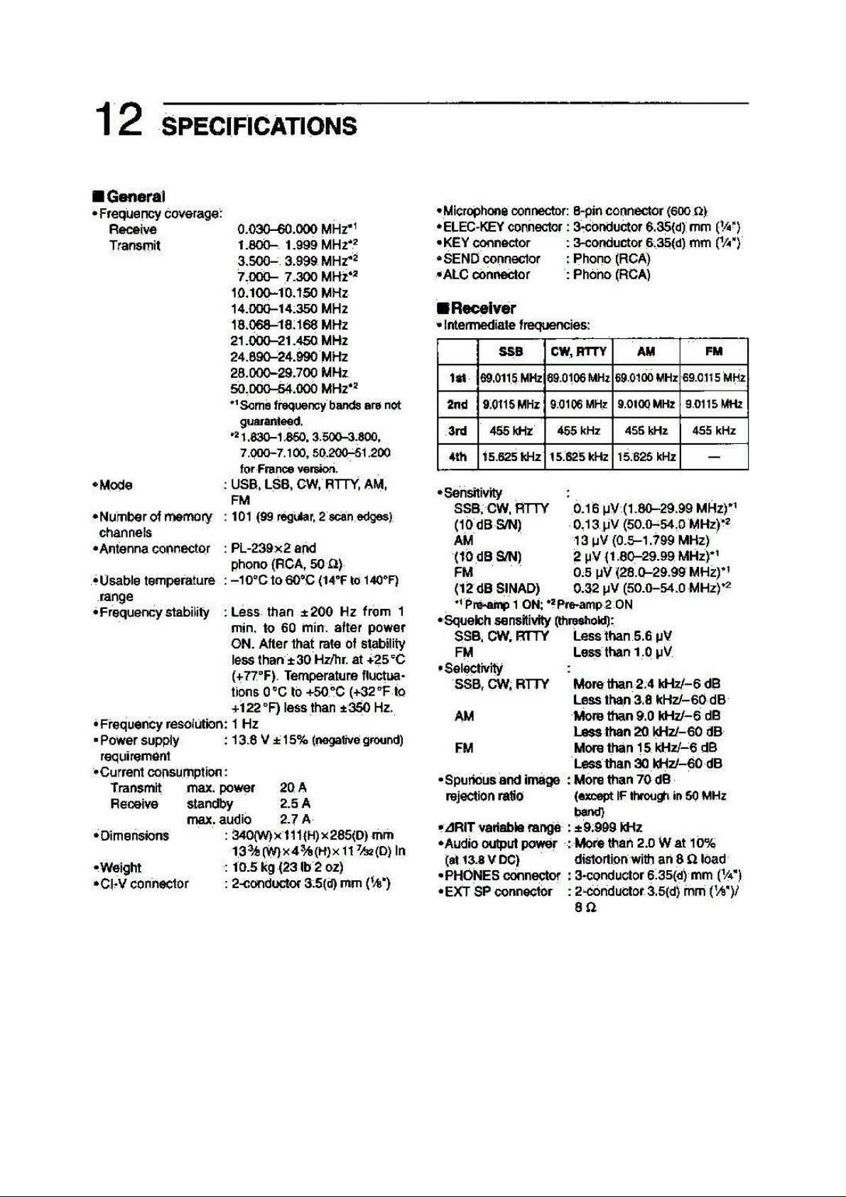
SW 100, Kenwood TS50 und der ICOM IC756. Ich bevorzugte letzteren, da dieser mit einem 9
khz ZF-Filter ausgerüstet ist, welches über die benötigte Spezifikation verfügt (9khz/-6dB und
20khz/-60dB). Und idealerweise auch noch mit einem freien Pin an der ACC2-Buchse. Die
grosse Frage war nun, ob auch ein entsprechender Platz für den Einbau des Mischers gefunden
werden könnte und wie es mit den Anschlussmöglichkeiten für die ZF-Auskopplung aussah,
denn die Platine ist in SMD-Technologie bestückt! Ein sehr, sehr naher Blick auf die Platine der
Transceiverunterseite verschaffte Klarheit: Ein idealer 1,5 cm2 freier Platz fand sich genau dort,
wo die einzige Möglichkeit zur ZF-Auskopplung bestand: Ein Trimmpoti, dass sich dazu anbot
genau hier das Anlöten mittels normalem Weller Lötkolben und schmaler Spitze (1,5mm /
380°C) zu versuchen.
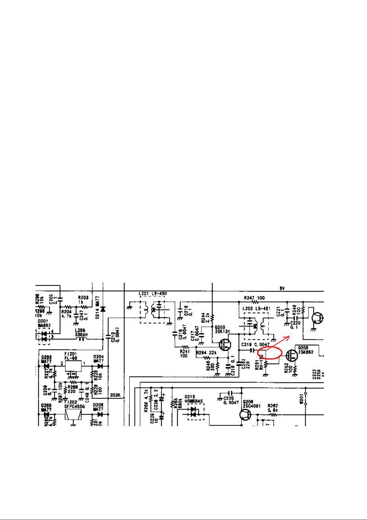
Die Verbindung wurde an dem besagten Trimmpoti (zwischen C219 und R251) hergestellt. Die
Stromversorgung für den Mischer erfolgte über Pin7 der ACC2-Buchse und der Mischerausgang
wurde zum Pin6 hergestellt. Die Masseverbindung erfolgte über eine direkt nebem dem Mischer
befindliche Schraube. Befestigt wurde die Mischerplatine mittels doppelseitigem Klebeband und
- da es sich um die Transceiverunterseite handelt - mittes eines zusätzlichen
Schaumgummistücks.(Siehe beigefügte Fotos und Schaltplan).
Ein Test mit dem Oscilloskope zeigte die erforderlichen 12 khz, aber der erste
Test mit der FhG Software schlug fehl. Das RF-Meter zeigte nichts an und aus dem Lautsprecher
kam - nichts.
>>Bemerkung des Editors: Alle Bildschirmfotos zeigen die professionelle FhG Software. Eine
vollständige Beschreibung dieser Software findet sich auf der FhG Web site (www.fhg.de)<<
Wo lag der Fehler ?
Ich hatte mir 2 Fallen gestellt:
Die Steuerung des RF-Meters erfolgte in der Originalkonfiguration über die Fernsteuerung des
AOR-Empfängers, aber der ICOM wurde nicht ferngesteuert. Doch das Spektrum sah gut aus
und das IF-Meter zeigte auch die vom AOR-Empfänger gewohnten Werte. Lediglich die StatusLEDs wollten nicht in den OK-Zustand gehen. - Die Lösung liegt in der zusätzlichen ZF-Stufe
des ICOM-Empfängers: Die 455khz Stufe ist bereits die 3. ZF und so war das Spektrum
gegenüber den 2 Stufen des AOR-Empfängers invertiert. Ein Blick in das Radio User Manual
der FhG Software löste auch dieses Problem: Nach dem Start der Software mittels des
zusätzlichen Parameters "specinv" stand dem klaren Empfang der verschiedenen DRM-Stationen
nichts mehr im Wege.
>>Bemerkung des Editors: Jürgen hatte ein invertiertes Spektrum, welches auf den AMEmpfang keine Auswirkungen hat, wohl aber beim DRM-Empfang. Der FhG SoftwareEmpfänger ist jedoch in der Lage, auch das invertierte Spektrum zu verarbeiten, muss dazu
jedoch mittels des o.g.zusätzlichen Kommandos gestartet werden.<<
Jürgen Wagner
MES Bockhacken
DRM Modification ICOM IC756 Transceiver
A 455 kHz type crystal option of the DRM mixer from SAT-Service Schneider / Germany was
obtained. (http://home.t-online.de/home/sat-service/sat/DRM/DRM.htm)
Some different types of receiver were available to me: Grundig Yachtboy, Sony ICF SW 100,
Kenwood TS 50 and the ICOM IC 756. I preferred the last one, because it has specified a 455
kHz IF AM filter with 9 khz/-6db and 20khz/-60 db selectivity. And ideal - a free pin at the
Page 2
accessory socket No 2! - But would it be possible to find a place for the mixer and a point where
the tap could be soldered? (It's SMD technology!). A (very) closer look at the transceivers
bottom gives clearance: Yes there is an ideal 1.5 cm2 SMD free place near that point, where 455
kHz IF is available. And there is a device, a trimpot, that could be OK for soldering the tap to
with a normal Weller solder-iron (1.5mm / 380 deg. centigrade).
The connection was made between C219 and the trimpot R251. Power comes from pin 7 of the
ACC2 socket. Mixer output goes to pin 6. Ground exists at a screw directly beside the mixer.
The mixer was fixed with double sided adhesive tape and (because it is the underside of the unit)
additional foam rubber. (Look at the attached schematic extract and mounting pictures).
A test with the oscilloscope shows 12 kHz OK. But the first test with the FhG software fails.
Editors note: all screenshots are taken with the professional FhG version of the software. Full
details of this software can be found on the FhG web site (www.fhg.de).
The RF level meter shows nothing and no audio. What is wrong?
I have run into two traps:
RF level meter reading comes original via remote control from the AOR receiver - the ICOM
wasn't controlled. But spectrum looks good and IF meter reading was also OK despite wrong
status LED's and no output. - The solution is the IC756 IF processing: The 455 kHz is the 3rd IF
so the spectrum is inverted (compared to the AOR 7030 receiver). A look in the FhG software
radio user manual resolves this problem. After starting the software with the command line
switch "specinv" we had beautiful sound from various DRM stations.
Editor’s note: Jürgen had an inverted spectrum, this doesn’t mater for AM where the upper and
lower sidebands would be swapped, but it does for DRM. But the receiver can cope with an
inverted spectrum with an extra command line.
Jürgen Wagner
MES Bockhacken
Page 3
Page 4

Page 5

Page 6

Page 7

Page 8

Page 9

 Loading...