

Page 1
INSTRUCTION MANUAL
HF/VHF
ALL MODE TRANSCEIVER
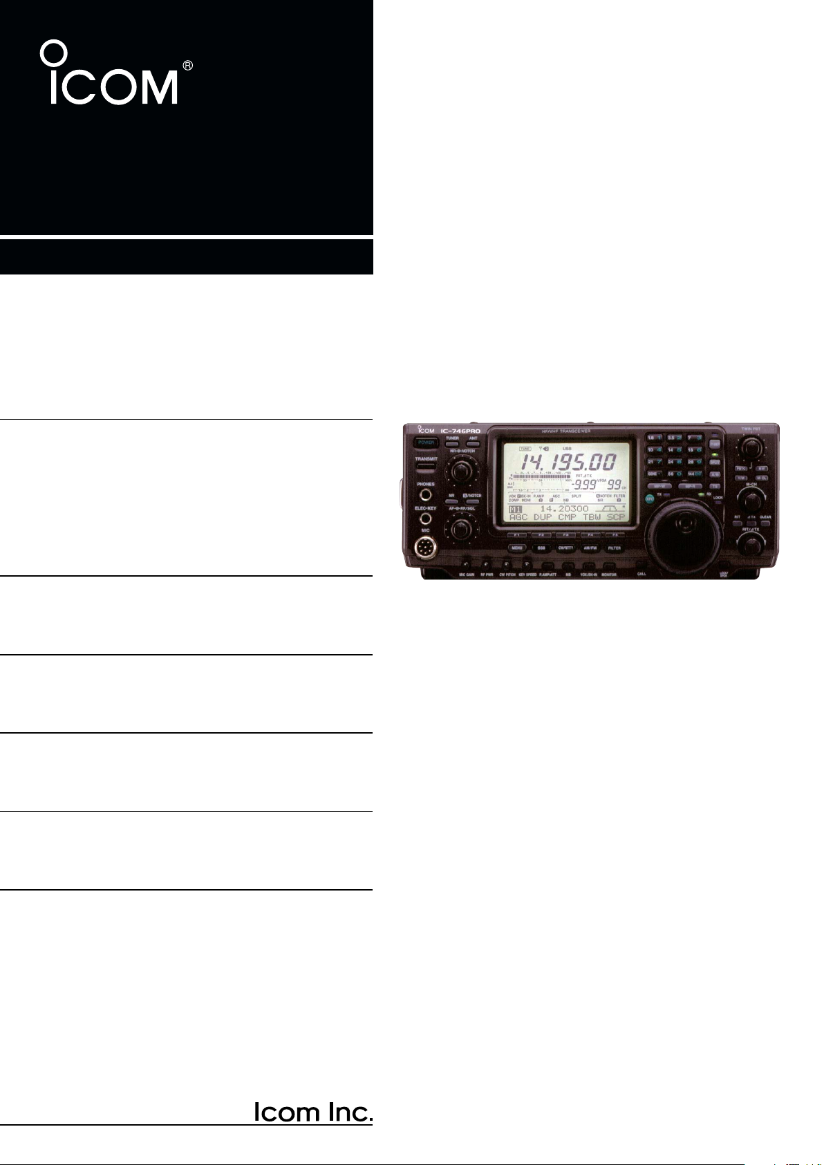
i746PRO
This device complies with Part 15 of the FCC rules. Operation is subject to the following two conditions: (1) This device may not cause
harmful interference, and (2) this device must accept any interference
received, including interference that may cause undesired operation.
Page 2

FOREWORD
PRECAUTIONS
We understand that you have a choice of many different radios in the market place. We want to take a couple of moments of your time to thank you for making
the IC-746PRO your radio of choice, and hope you
agree with Icom’s philosophy of “technology first”.Many
hours of research and development went into the design of your IC-746PRO.
Rather than completely redesigning all areas to create
a new radio, the engineering team at Icom decided to
follow in the footsteps of the IC-746 (one of the best
value transceivers in the marketplace) with the new
“PRO.” Focused on real world improvements compiled
over the last few years from letters, phone calls, EMails and newsgroup postings, the engineering team
at Icom is proud to say “many of these changes were
compiled from a list of suggestions from you, the amateur radio operator!”
FEATURES
• 32-bit Floating point DSP and 24-bit AD/DA converter
• DSP IF Filter creates 102 types of filter
• All mode capability covering 160–2 m
• 100 Watt continuous duty cycle
• All mode digital modulation and demodulation
• RTTY demodulator and decoder
• Twin Pass Band Tuning
• RF speech compression with selectable pass band
• Microphone Equalizer
• SSB/CW synchronous tuning
IMPORTANT
READ THIS INSTRUCTION MANUAL
CAREFULLY before attempting to operate the
transceiver.
SAVE THIS INSTRUCTION MANUAL. This
manual contains important safety and operating instructions for the IC-746PRO.
EXPLICIT DEFINITIONS
WORD DEFINITION
RR
WARNING
CAUTION Equipment damage may occur.
NOTE
i
Personal injury, fire hazard or electric
shock may occur.
If disregarded, inconvenience only. No
risk or personal injury, fire or electric
shock.
R WARNING RF EXPOSURE! This device emits
Radio Frequency (RF) energy. Extreme caution should be
observed when operating this device. If you have any
questions regarding RF exposure and safety standards
please refer to the Federal Communications Commission
Office of Engineering and Technology’s report on Evaluating Compliance with FCC Guidelines for Human Radio
Frequency Electromagnetic Fields (OET Bulletin 65).
R WARNING HIGH VOLTAGE! NEVER attach an
antenna or internal antenna connector during transmission. This may result in an electrical shock or burn.
R NEVER apply AC to the [DC13.8V] jack on the trans-
ceiver rear panel. This could cause a fire or ruin the transceiver.
R NEVER apply more than 16 V DC, such as a 24 V
battery, to the [DC13.8V] jack on the transceiver rear
panel. This could cause a fire or ruin the transceiver.
R NEVER let metal, wire or other objects touch any in-
ternal part or connectors on the rear panel of the transceiver. This may result in an electric shock.
NEVER expose the transceiver to rain, snow or any liquids.
AVOID using or placing the transceiver in areas with tem-
peratures below –10°C (+14°F) or above +60°C (+140°F).
Be aware that temperatures on a vehicle’s dashboard can
exceed 80°C (+176°F), resulting in permanent damage to
the transceiver if left there for extended periods.
AVOID placing the transceiver in excessively dusty environments or in direct sunlight.
AVOID placing the transceiver against walls or putting
anything on top of the transceiver. This will obstruct heat
dissipation.
Place unit in a secure place to avoid inadvertent use by
children.
During mobile operation, DO NOT operate the transceiver
without running the vehicle’s engine. When the transceiver’s power is ON and your vehicle’s engine is OFF,
the vehicle’s battery will soon become exhausted.
Make sure the transceiver power is OFF before starting
the vehicle. This will avoid possible damage to the transceiver by ignition voltage spikes.
During maritime mobile operation, keep the transceiver
and microphone as far away as possible from the magnetic
navigation compass to prevent erroneous indications.
BE CAREFUL! The heatsink will become hot when operating the transceiver continuously for long periods.
BE CAREFUL! If a linear amplifier is connected, set the
transceiver’s RF output power to less than the linear amplifier’s maximum input level, otherwise, the linear amplifier will be damaged.
Use Icom microphones only (supplied or optional). Other
manufacturer’s microphones have different pin assignments, and connection to the IC-746PRO may damage
the transceiver.
Page 3

TABLE OF CONTENTS
qw
ert
FOREWORD ........................................ i
IMPORTANT ........................................ i
EXPLICIT DEFINITIONS ..................... i
PRECAUTIONS ................................... i
TABLE OF CONTENTS ...................... ii
QUICK REFERENCE GUIDE ........ I–X
■ Installation ....................................... I
■ Operation ....................................... III
■ Your first contact ........................... IV
■ Ready to call CQ? ......................... IX
1 PANEL DESCRIPTION ........... 1 – 12
■ Front panel ..................................... 1
■ Rear panel ...................................... 7
■ LCD display .................................... 9
■ Multi function switches .................. 11
■ Microphone (HM-36) .................... 12
2 INSTALLATION AND
CONNECTIONS ................... 13 –17
■ Unpacking .................................... 13
■ Selecting a location ...................... 13
■ Grounding ..................................... 13
■ Antenna connection ...................... 13
■ Required connections ................... 14
■ Advanced connections ................. 15
■ Power supply connections ............ 16
■ Linear amplifier connections ......... 17
■ External antenna tuner
connections .................................. 17
3 BASIC OPERATION ............. 18–25
■ When first applying power
(CPU resetting) ............................. 18
■ Initial settings ................................ 18
■ Selecting an operating band ........ 19
■ Selecting VFO/memory mode ...... 20
■ VFO operation .............................. 20
■ Frequency setting ......................... 21
■ Operating mode selection ............ 23
■ Volume setting .............................. 23
■ Squelch and receive (RF)
sensitivity ...................................... 24
■ Basic transmit operation ............... 25
4 RECEIVE AND TRANSMIT .. 26 –46
■ Operating SSB ............................. 26
■ Operating CW ............................... 27
■ Electronic keyer functions ............ 29
■ Operating RTTY (FSK) ................. 35
■ RTTY functions ............................. 36
■ Operating AM ............................... 40
■ Operating FM ............................... 41
■ Repeater operation ....................... 44
5 FUNCTIONS FOR RECEIVE
........................................... 47 –54
■ Simple band scope ....................... 47
■ Preamp/Attenuator ....................... 48
■ RIT function .................................. 48
■ AGC function ................................ 49
■ IF filter selection ........................... 50
■ IF (DSP) filter shape ..................... 51
■ Noise blanker ............................... 51
■ Meter peak hold function .............. 51
■ Twin PBT operation ...................... 52
■ Noise reduction ............................ 53
■ Notch function .............................. 53
■ Dial lock function .......................... 53
■ Voice squelch control function ...... 54
6 FUNCTIONS FOR TRANSMIT
........................................... 55 –61
■ VOX function ................................ 55
■ Break-in function .......................... 56
■ ∂TX function ................................ 57
■ Monitor function ............................ 57
■ Speech compressor ..................... 58
■ Transmit filter width selection ....... 58
■ Split frequency operation .............. 59
■ Quick split function ....................... 60
■ Measuring SWR ........................... 61
7 MEMORY OPERATION ........ 62–68
■ Memory channels ......................... 62
■ Memory channel selection ............ 62
■ Programming a memory ............... 63
■ Memory clearing ........................... 63
■ Selecting the call channel ............. 64
■ Programming the call channel ...... 64
■ Frequency transferring ................. 65
■ Programming scan edges ............ 66
■ Assigning memory names ............ 67
■ Memo pads ................................... 68
8 SCANS ................................. 69 –74
■ Scan types .................................... 69
■ Preparation ................................... 69
■ Voice squelch control function ...... 70
■ Scan set mode ............................. 70
■ Programmed scan/Fine programmed
scan .............................................. 71
■ Memory scan operation ................ 72
■ Select memory scan ..................... 72
■ ∂F scan operation and Fine ∂F scan
...................................................... 73
■ Tone scan/DTCS code scan
operation ...................................... 74
9 ANTENNA TUNER OPERATION
............................................ 75–77
■ Antenna connection and selection 75
■ Antenna tuner operation ............... 76
■ Optional external tuner operation . 77
10 DATA COMMUNICATION ..... 78– 80
■ Connections ................................. 78
■ Packet (AFSK) operation .............. 79
■ Adjusting the TNC output level ..... 80
■ Data transmission speed .............. 80
11 SET MODE ............................ 81–89
■ General set mode ......................... 81
■ Tone control set mode .................. 89
12 OPTION INSTALLATION ..... 90–91
■ Opening the transceiver’s case .... 90
■ UT-102
■ CR-338
VOICE SYNTHESIZER UNIT
HIGH STABILITY CRYSTAL UNIT
..................................................... 91
... 90
13 MAINTENANCE .................... 92–94
■ Trouble shooting ........................... 92
■ Fuse replacement ......................... 93
■ Tuning dial brake adjustment ....... 93
■ Resetting the CPU ........................ 94
■ Frequency calibration (approximate)
..................................................... 94
14 CONTROL COMMAND ......... 95–99
■ Remote jack (CI-V) information .... 95
15 SPECIFICATIONS...................... 100
16 OPTIONS.................................... 101
SUPPLIED ACCESSORIES
The transceiver comes with the following accessories.
q DC power cable (OPC-025D) ............................ 1
w Hand microphone (HM-36) ................................ 1
e Spare fuses (FGB 30 A) .................................... 2
r Spare fuse (FGB 5 A) ........................................ 1
t CW keyer plug (AP-330) .................................... 1
Icom, Icom Inc. and the logo are registered trademarks of Icom Incorporated (Japan) in the United States, the United Kingdom, Germany, France, Spain, Russia and/or other countries.
Qty.
ii
Page 4
QUICK REFERENCE GUIDE
30 A fuses
AC cable
Transceiver
AC
outlet
A DC power
supply*
*13.8 V; at least 23 A
continuous
Black
_
Red
+
to DC power
socket
Supplied
DC power cable
PS-125
DC power
socket
Transceiver
DC power cable
Connect to an AC outlet using the supplied AC cable.
■ Installation
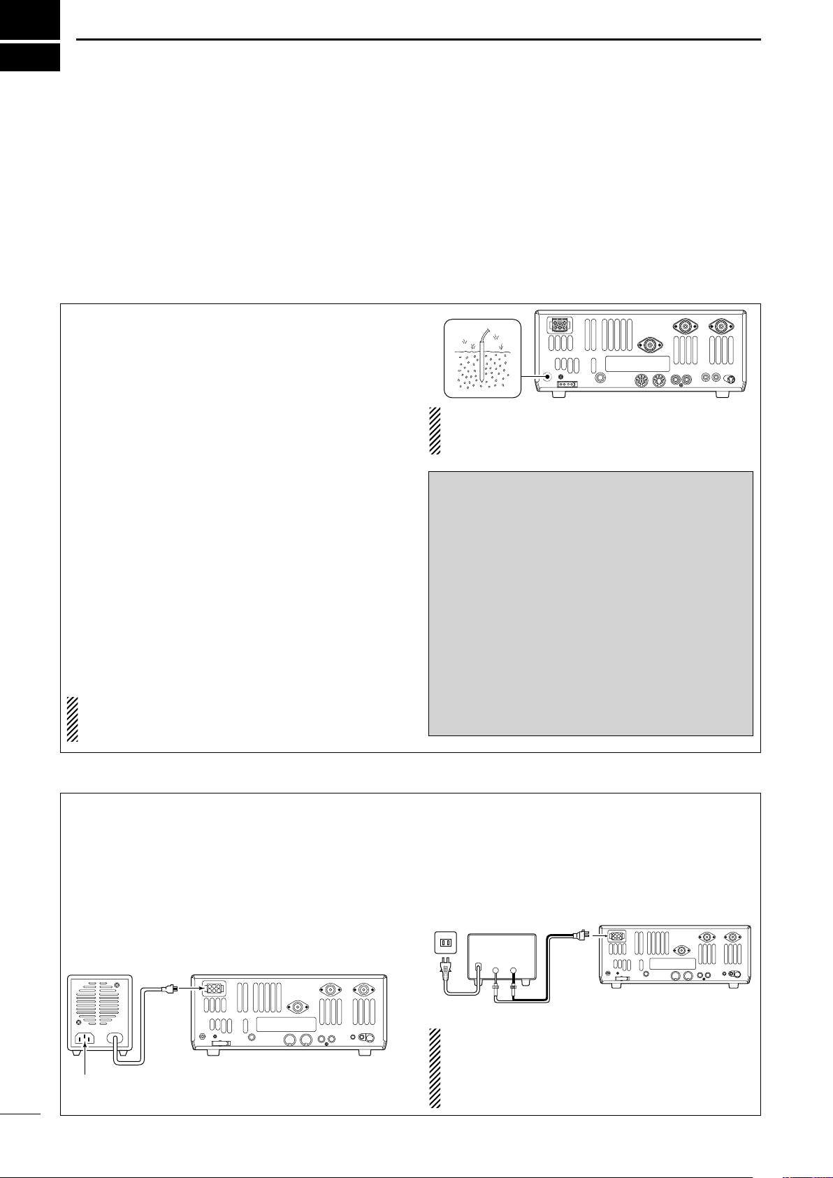
1. Install a ground system for DC noise suppression
and RFI suppression
2. Install your DC power supply
3. Install lightning protection. This will help protect
more than your gear.
1. Grounding your Shack
Although your radio will operate by connecting the DC
power supply and antenna, it is necessary to have a
good ground system in your shack. A ground connection is the electrical contact between the common point
of an electrical or electronic system and the earth.
A good earth ground is necessary to prevent electrical
shock, eliminate problems from RFI and DC noise.
With more electronic devices being used today, it is
also important to reduce RFI and EMI. Although you
may not see interference in your shack, without a
grounding system, your neighbors may experience interference. Even though many of these devices are
Part 15, where they must accept interference from
their surrounding environment, it is best to eliminate
as much of the possible interference from your shack.
If you do not have a grounding system for your shack,
depending on the location of your shack, basement or
ground floor, a good ground system can be as simple
as a couple of ground rods driven 6 to 8 feet into the
soil. When installing your IC-746PRO to your grounding system, the shortest most direct connection is recommended.
NOTE: There are many publications covering
proper grounding techniques. Check with your local
dealer for more information and recommendations.
4. Install and connect an antenna system for the appropriate bands of operation
5. Connect other peripheral equipment. This includes
microphones, headsets, TNC, amplifiers and any
other equipment necessary to make your shack
complete.
R WARNING!: NEVER ground station equip-
ment or antennas to house gas lines. NEVER at-
tach ground lines to plastic (pvc) pipe.
DD
Some Symptoms if inadequate grounding
a. Poor DC Ground
60 Hz hum on the audio either Rx or Tx without the
antenna connected.
If you feel a tingling sensation when you touch a
metal surface. Surfaces such as the cover of your
radio or power supply.
b. Poor RF Ground
While transmitting and you feel a tingling sensation
when you touch a metal surface. Surfaces such as
the cover of your radio or power supply.
While transmitting, you experience interference to
other electronic devices, such as the telephone,
television or stereo audio systems.
2. Installing your DC Power Supply
The DC power supply is a device used to convert
110/220 V AC, also know as Household current, to a
steady source of 13.8 V DC.
The perfect match to your IC-746PRO is the PS-125.
This compact switching power supply is the matching
power supply for your IC-746PRO with a current rating of 25 A continuous duty. This plug and play unit
plugs into the DC jack located on the rear of the radio.
I
• If you are not using the PS-125:
Connect the supplied DC power cable (OPC-025D) to
the appropriate color coded terminals, then insert the
DC connector into the DC jack located on the rear of
the radio.
NOTE: Although the power supply current requirement is quite low during receiving, this not the case
when you transmit. With many electrical devices in
the shack, it is very important to verify the electrical
circuit is not overloaded.
Page 5
3. Installing lightning protection
30 mm
10 mm (soft solder)
10 mm
1–2 mm
solder solder
Soft
solder
Coupling ring
Slide the coupling ring
down. Strip the cable
jacket and soft solder.
Slide the connector
body on and solder it.
Screw the coupling
ring onto the
connector body.
Strip the cable as
shown at left. Soft solder the center conductor.
q
w
e
r
ANTENNA 1, 2
[Example]: ANT1 for 1.8–18 MHz bands
ANT2 for 21–50 MHz bands
144 MHz ANTENNA
Connect a VHF (60–144 MHz)
antenna; impedance: 50 Ω.
Although you may not live in an area with high occurrence for lightning storms, it is always wise to take
precautions for lightning or static discharges. Proper
lightning protection not only offers protection to the
ham gear, but the shack and most importantly the operator.
4. Installing your antenna system
Whether your IC-746PRO is your first radio or one of
many, one of your key elements in a great shack is
the antenna system. There are three connections on
the back of your IC-746PRO, two for HF and 6 m and
one for 2 m. If you are using one antenna for HF and
6 m, for simplicity, connect the antenna coax to ANT1.
QUICK REFERENCE GUIDE
NOTE: There are many publications covering
proper lightning protection, check with your local
dealer for more information and recommendations.
Antenna SWR
Each antenna is tuned for a specified frequency
range and SWR may be increased out-of-range.
When the SWR is higher than approx. 2.0:1, the
transceiver’s power drops to protect the final transistors. In this case, an antenna tuner is useful to
match the transceiver and antenna. Low SWR allows full power for transmitting even when using the
antenna tuner. The IC-746PRO has an SWR meter
to monitor the antenna SWR continuously.
Your IC-746PRO is equipped with an internal antenna
tuner (ATU) for operation on 160–6 m. This ATU is designed to work with an unbalanced 50 Ω feedline. The
purpose of the internal antenna tuner is to match the
impedance of your antenna system to as close to a
50 Ω load as possible. This ATU will not operate with
a long wire or ladder line (450 Ω or other balanced
feedlines). An external ATU such as the AH-4 would
be necessary for this kind of operation.
PL-259 CONNECTOR INSTALLATION EXAMPLE
30 mm ≈9⁄8 in 10 mm ≈3⁄8 in 1–2 mm ≈1⁄16 in
R WARNING: Although a mag mount antenna
works great on a vehicle, DO NOT use the IC746PRO with this type of antenna.
CAUTION: Although your IC-746PRO has protection to drop down power with a high SWR, this
does not completely protect the transceiver from
transmission without an antenna. Make sure you
have an antenna connected whenever you transmit with your radio.
NOTE: There are many publications covering
proper antennas and their installation, check with
your local dealer for more information and recommendations.
II
Page 6
QUICK REFERENCE GUIDE
MICROPHONES
HM-36 SM-20
STRAIGHT KEY
(+)
(_)
CW KEY
A straight key can be used when the internal
electronic keyer is turned OFF in keyer set
mode. (p. 34)
(dot)
(com)
(dash)
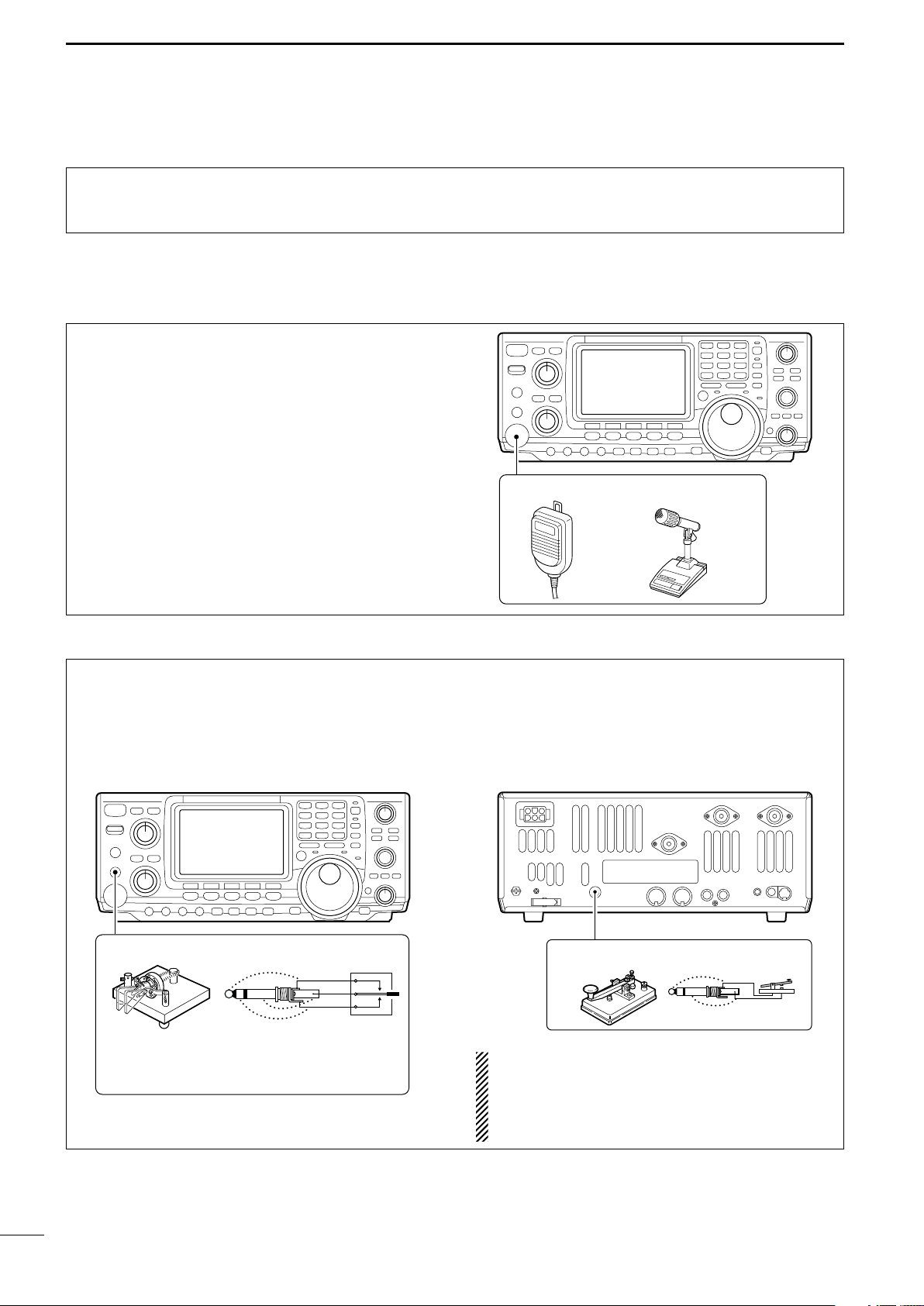
5. Connect other peripheral equipment
Everyone has his or her favorite ad-on gear; now is
the time to connect this gear! We will cover the basic
devices that can be connected to your IC-746PRO.
■ Operation
1. Voice
Microphones: Connect the microphone to the eightpin connector on the front of the radio.
If you do not see the particular item you are wanting
to connect, refer to the Advance Connections section
starting on page 15.
2. CW
CW Key: There are several types of keys or keyers
that can be used with your IC-746PRO.
a. Iambic Key paddle: Use a 6.35(d) mm (1⁄4″) stereo
plug and connect to the [ELEC-KEY] jack located
on the front of the radio.
III
b. Straight Key: Use a 6.35(d) mm (1⁄4″) mono plug
and connect key to the back of the radio.
c. External Keyer: Use a 6.35(d) mm (1⁄4″ ) mono
plug and connect to the back of the radio.
1
d. Computer Keying: Use a 6.35(d) mm (
⁄4″) mono
plug and connect to the back of the radio.
NOTE: You will need to select the type of keyer you
are using in the Keyer Set mode. There are many
advanced CW functions in this set mode. Until you
have a full understanding of these functions
change only the items necessary.
Page 7
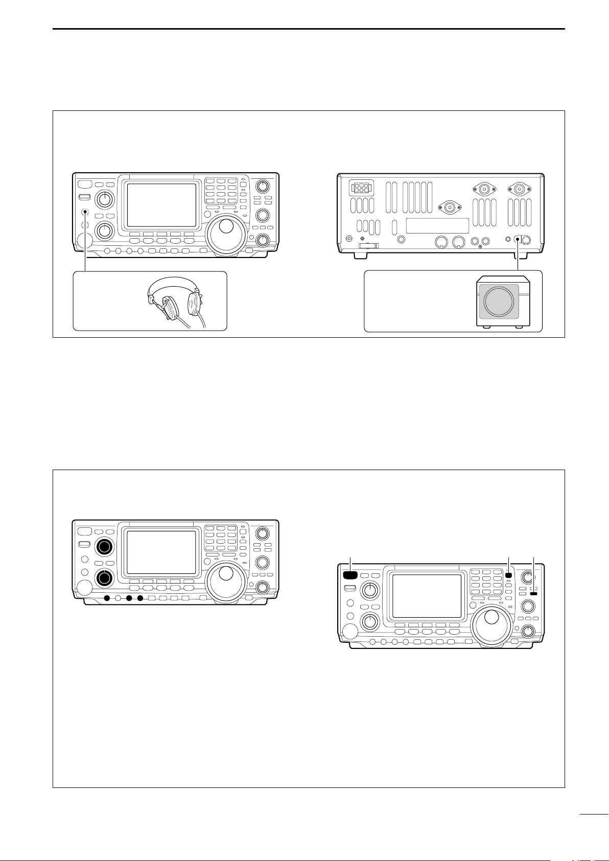
3. Other convenient items
EXTERNAL SPEAKER
SP-21 (optional)
HEADPHONES
[POWER] [F-INP] [M-CL]
Headphones:
A 6.35(d) mm (1⁄4″) mono jack for operation without
using the internal or external speakers. Perfect for operation without disturbing others in the room.
QUICK REFERENCE GUIDE
External Speaker:
A 3.5(d) mm (1⁄8″) mono jack for operation with an ex-
ternal speaker. (Input impedance: 8 Ω/Max. input
power: 5 W)
■ Your first contact
Now you should have your IC-746PRO installed in
your shack, and like a kid on his birthday, you are
probably excited to get on the air. We would like to
take you through a few basic operation steps to make
your first “On The Air” an enjoyable experience.
DD
Getting started
1. Before powering up your radio, you may want to
make sure the following controls are set in the following positions:
•[AF] : Commonly referred to as the vol-
ume: fully counter clockwise.
•[NR] : The noise reduction control: fully
counter clockwise.
•[MIC GAIN] : The mic gain: fully counter clock-
wise.
•[RF/SQL] : The control for the RF Gain and
Squelch circuits: 12 o’clock.
•[CW PITCH] : The control for the CW pitch:
12 o’clock.
•[KEY SPEED] : Internal CW Keyer Speed: fully
•[NOTCH] : Control for the manual notch:
counter clockwise
12 o’clock
2. Resetting the CPU: Although you have purchased
a brand new radio, some settings may be changed
from the factory defaults during the QC process. So
your radio can start from Factory Defaults resetting
the CPU is necessary.
IV
Page 8

QUICK REFERENCE GUIDE
GENE
50
0
21
7
24
8
28
9
14
5
10
4
18
6
3.5
2
1. 8
1
7
3
144
ENT
Either “1” or “2” appears.
*No indicator appears during
144 MHz operation.
AF RF/SQL
No audio output
Max. audio output
Decreases Increases
DD
Just listening
1. Select the desired band
On your IC-746PRO, an easy way of changing bands
is by using the keypad located just above the tuning
knob on the right hand side of the display. You will notice each switch has two sets of numbers; one set of
numbers represents the band selection.
2. Tune to the desired frequency
Directly below the keypad is the tuning knob. This will
allow you to dial in the frequency you want to operate. You will notice the tuning speed [TS] is 10 Hz resolution. Page 22 will instruct you on how to set the
tuning speed [TS] for 1 Hz resolution.
•Say you want to go to 20 meters or 14 MHz; you
would push the [145]. This will immediately change
the displayed operating frequency to the 20-meter
band. By pushing [145] again, frequency pre-sets
in the triple band stacking registers frequency can be
displayed. For more details on this system refer to
p. 19.
NOTE: Although you can directly enter the frequency with the keypad, using the Band Stacking
Register and the tuning knob is the most popular
method of hoping around the bands. For more information regarding the direct frequency entry
method, refer to p. 22.
3. Verify proper antenna has been selected.
You IC-746PRO has three antenna connectors. Two
for HF and 6 m and a one for 2 m. The selection for
2 m is automatic, where the HF and 6 m is user selectable for either one of the antenna jacks. For first
time use, the antenna selector should show “” on
the display of your radio. Verify the antenna selected
on the display is the antenna port your antenna is
connected to.
4. Adjust audio output
Adjust this control to a comfortable audio level.
V
Page 9
DD
AGC DUP CMP TBW SCP
[NR] [NR]
Appears
What are you hearing?
Stop and focus on what you are hearing. Do you hear
a lot of noise? Is the signal intelligible? Are you set up
for the right mode? How about the filters?
1. Verify mode
QUICK REFERENCE GUIDE
Although your IC-746PRO will automatically select
USB or LSB in the HF bands, it will not select any of
the other modes. You will need to select the proper
mode whether CW, RTTY, AM or FM.
2. Reducing interference
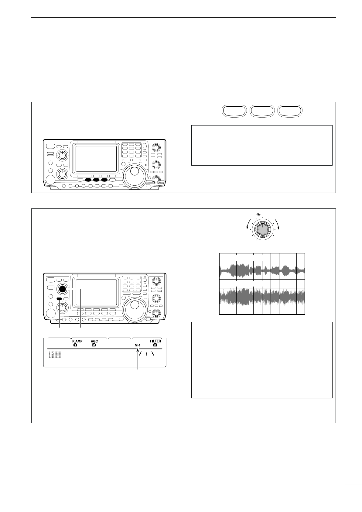
Your IC-746PRO has many features to reduce QRM
and QRN from the desired signal.
a. Noise Reduction: The noise reduction system on
your IC-746PRO is part of the 32-bit DSP. This is
used to reduce the hiss and QRM levels. To activate, push the [NR] switch located just to the right
of the [PHONES] jack.
SSB
CW/RTTY
AM/FM
Hint!
The Triple Band Stacking Register will memorize
the last three frequencies used in the band, as well
as the Mode, Filter, Tuner and AGC settings. This
makes band hoping much easier.
NR NOTCH
Decreases
OFF
Noise reduction ON
Increases
b. Adjusting the Noise Reduction: The noise re-
duction is completely variable on how much of the
DSP Noise Reduction is used [NR] level control located just above the [NR] switch.
Noise reduction OFF
Hint!
How far you advance the NR control will determine
how much the noise can be effectively reduced.
Turning the control too far clockwise may cause
some distortion to occur on the received signal. The
NR control should only be turned as far clockwise
as is necessary. Use this control, along with RF
gain, NB (noise blanker, if needed), and IF filters as
well, to minimize the effects of noise on the target
signal.
VI
Page 10
QUICK REFERENCE GUIDE
AGC DUP CMP TBW SCP
[A/NOTCH] [NOTCH]
Notch function indicators
NR NOTCH
Low frequency High frequency
BW
• Filter set mode indication
Shows the selected filter and passband width.
BW
• Indication while setting
While pushing [F1 BW], rotate the tuning dial to set
passband width.
Reverses Appears
AGC DUP CMP TBW SCP
[FILTER]
The selected filter width is indicated
for approx. 1 sec. when [FILTER] is
pushed.
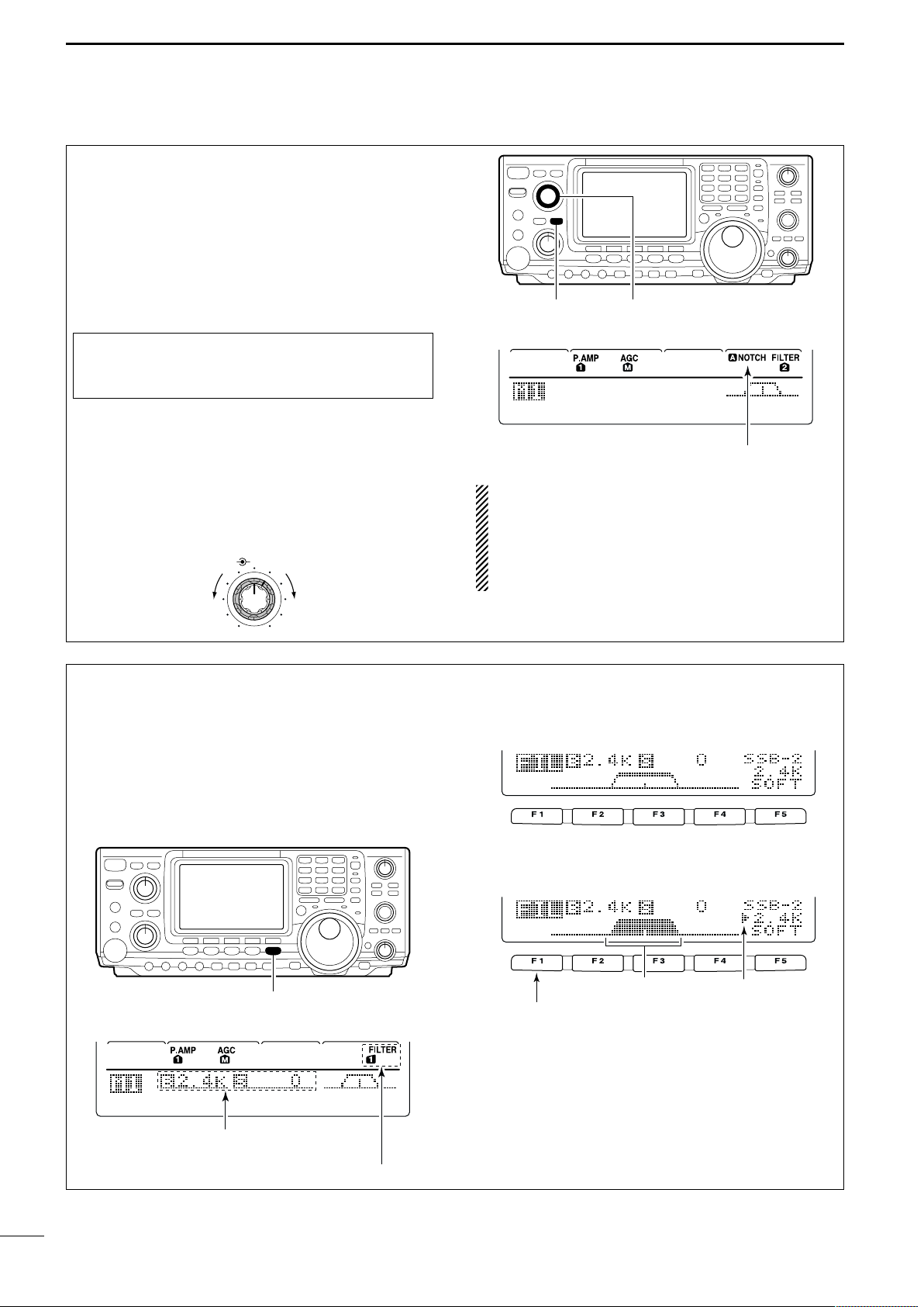
Filter selection
c. Notch: There are two notch systems on your IC-
746PRO.
•Automatic: The automatic notch will track up to three
heterodynes. This is helpful for eliminating annoying
transmitter “tune up” tones on any band, and to minimize continuous tone “heterodynes” encountered on
the 40 meter phone bands at night, for example.
Once selected an icon will appear “A NOTCH” on
the display.
Hint!
The Automatic Notch will not operate in the SSB
data, CW or RTTY modes.
•Manual: The Manual notch provides 70 dB of atten-
uation to pin point an interfering signal. The 12 o’-
clock position is on the operating frequency, turning
the Notch knob clockwise moves the notch up the
band and counter clockwise will move the notch
down the band. Once selected an icon “NOTCH” will
appear on the display.
NOTE: Your IC-746PRO is equipped with multiple
AGC circuits. This allows the DSP to filter out interfering signals and QRM, while also taking this interference out of the AGC. Bottom line, this will either eliminate or greatly reduce the pumping of the
AGC from the interfering signal.
d. Filters: Your IC-746PRO has an incredible IF DSP
based filter network with over 100 settings.
•Dial in your filters: By pushing [FILTER] for 1 sec.,
you enter the filter set mode. This is where you are
able set the three filter presets. Across the bottom of
the display you will see the “BW” icon. The switch directly below, along with the tuning dial, will be used
to select the changes you will make.
VII
Page 11
QUICK REFERENCE GUIDE
BW
• Filter set mode indication
Shows the selected filter and passband width.
BW
• Indication while PBT setting
Appears when passband is shifted.
*By pushing [PBTC] for 1 sec., the shifted value returns
to the default setting, and the “dot” disappears.
AGC DUP CMP TBW SCP
Passband width and shifting value are
indicated while [TWIN PBT] is operated.
[TWIN PBT] control
[PBTC]
Appears when PBT is used.
One of “1,” “2” or “3” is
displayed for selected filter
number indications.
d. Filters:— continued
•
On the fly adjustment: Once the adjustments have
been made in the filter set mode, you can make on
the fly changes by using the Twin Pass Band Tuning,
Twin PBT. You will be able to see the effects of the
Twin PBT on the upper left hand side of the screen.
NOTE: The Twin PBT filters shift the two IF DSP
filters (See Diagrams below and right). This feature
allows both an IF shift as well as a narrowing of the
Pass Band. Although you can narrow the pass
band by shifting the two filters, this does not narrow both filters, thus the filter shape is not narrowed. You may hear some signal artifacts pass
through this filter adjustment.
PBT operation example
Center
IF center frequency
interference
Passband
desired signal
pass band
inteference
Passband
desired signal
IF shift
IF center freq.
interference
VIII
Page 12
QUICK REFERENCE GUIDE
[F1 ≤]
Tuning dial[MENU]
[F2 ≥] [F4 TCN]
RX Bass
SSB
O
3
RX Treble
SSB
O
4
3. RX Tone Control:
Once you have mastered your filter settings, one last
feature to enable the most intelligible audio is the actual audio tone you hear. You can adjust the equalization of your received audio ±5dB.
q Push [MENU] several times, or until M2 is shown
on the display.
w Push [F4 TCN] for the Tone Control set mode.
e Push the appropriate mode switch to adjust SSB,
AM or FM.
r Push [F1 ≤] or [F2 ≥] to change to the desired
component.
1. RX Bass
This item adjusts the bass level of the receive audio
tone from –5 dB to +5 dB in 1 dB steps.
2. RX Treble
This item adjusts the treble level of the receive audio
tone from –5 dB to +5 dB in 1 dB steps.
We hope these pointers have been helpful. Now you
are ready for the “Ready to call CQ?”.
■ Ready to call CQ?
[NR]: Max. CCW [NOTCH]: Max. CCW
i746PRO
TUNER
POWER
TRANSMIT
[TRANSMIT]: OFF
PHONES
ELEC-KEY
[AF]: Max. CCW
MIC
[RF/SQL]: 12 o’clock
[MIC GAIN]: Max. CCW
[RF PWR]: Max. CCW [CW PITCH]: 12 o’clock
ANT
NR
NOTCH
/NOTCH
NR
A
AF
RF/SQL
F 1
MENU
MIC GAIN
RF PWR
CW PITCH
KEY SPEED
HF/VHF TRANSCEIVER
F 2F 3
SSB
CW/RTTY
P.AMP/ATT
NB
3.5
2
1
1.8
4
14
5
10
24
21
8
7
GENE
50
0
MP-W
TX
XFC
F 4
F 5
FILTER
AM/FM
VOX/BK-IN
MONITOR
CALL
[KEY SPEED]: Max. CCW
MP-R
F-INP
SPLIT
A/B
TWIN PBT
PBTC
MW
V/M
M-CL
LOCK/
SPCH
M-CH
RIT
CLEAR
∂TX
RIT/∂TX
TS
LOCK
3
7
6
18
28
9
144
ENT
RX
1. Setting up your transmit audio
The 32-bit DSP in your IC-746PRO is capable of allowing you to selects transmit audio for phone modes.
2. Mic Gain
The microphone gain is used for proper transmit
audio level for full output power.
IX
Page 13
F 1
F 2F 3
F 4
F 5
F 1
F 2 F 3 F 4 F 5
AGC DUP CMP TBW SCP
AGC DUP CMP TBW SCP
TX
BW=WIDE
Push [F4]
Push [F4] for 1 sec. to select the transmit filter width.
The selected transmit filter width
is displayed for approx. 1 sec.
3. DSP TX Audio Pass Band
TX Bass
SSB
O
1
TX Treble
SSB
O
2
The capability of changing the pass band of your
transmit audio, is at your finger tips. Regardless of the
condition of the speech compressor, you can adjust it
by selecting the [F4 TBW].
You will find this located in the M1 menu. By pushing
[F4 TBW] for 1 sec. you can select the TX audio band
pass.
There are three levels of audio passband width available (Wide, Mid, and Nar).
TX Audio Passband widths
Wide : 2.8 kHz ; Great Full Audio
Mid :2.4 kHz ; Great for operators with
deep full voices
Nar : 2.2 kHz ; Great for breaking through
pile ups
4. Microphone Equalizer
Although these bandwidths are fixed, the Microphone
Tone Control will give you more audio control for your
voice operation on SSB, AM, and FM modes. Your IC746PRO is equipped with a very powerful equalizer
system with 121 possible combinations. This is
achieved by using the separate bass and treble adjustments. The default for both the Base and Treble
is at 0 dB.
[F1 ≤]
QUICK REFERENCE GUIDE
[F2 ≥] [F4 TCN]
Entering Microphone Tone Control set mode:
q Push [MENU] several times, or until M2 is shown
on the display.
w Push [F4 TCN] for the Tone Control set mode.
e Push the appropriate mode switch to adjust SSB,
AM, or FM.
r Push [F1 ≤] or [F2 ≥] to change to the desired
component.
1. TX Bass
This item adjusts the bass level of the transmit audio
tone from –5 dB to +5 dB in 1 dB steps.
2. TX Treble
This item adjusts the treble level of the transmit audio
tone from –5 dB to +5 dB in 1 dB steps.
Verify you have selected a clear frequency
and call out your CQ!
Tuning dial[MENU]
Hint!
Voice patterns and audio characteristics vary with
each operator, therefore the [MIC GAIN], DSP TX
Audio Pass Band and Microphone Tone Control
settings will be different for each operator. Actual on
air experimenting is necessary to get just the right
sound. Listen to your transmit audio with headphones and the monitor function turned ON. It’s
also best to test and adjust your audio on the air,
while someone who knows what your real voice
sounds like listens, and provides and opinion on
your audio quality.
X
Page 14
1
Recommended level
RF gain
adjustable
range
Maximum
RF gain
S-meter
squelch
Noise squelch (FM mode)
Squelch is
open.
MODE
SSB, CW
RTTY
AM, FM
AUTO
RF GAIN
SQL
SQL
SET MODE SETTING
SQL
SQL
RF GAIN + SQL
RF GAIN + SQL
RF GAIN + SQL
(dot)
(com)
(dash)
POWER
TRANSMIT
PHONES
ELEC-KEY
MIC
NR
A
/NOTCH
TUNER
ANT
HF/VHF TRANSCEIVER
NR
NOTCH
AF
MIC GAIN
RF PWR
CW PITCH
F 1
F 2F 3
F 4
F 5
XFC
MP-W
GENE
50
0
21
7
24
8
28
9
14
5
10
4
18
6
3.5
2
1. 8
1
7
3
144
ENT
MP-R
TX
RX
LOCK
TS
SPLIT
F-INP
A/B
KEY SPEED
P.AMP/ATT
NB
VOX/BK-IN
MONITOR
CALL
LOCK/
SPCH
RF/SQL
i746PRO
MENU
SSB
CW/RTTY
AM/FM
FILTER
q
w
e
r
t
yuio !0 !1
!4!5!6!7 !3 !2
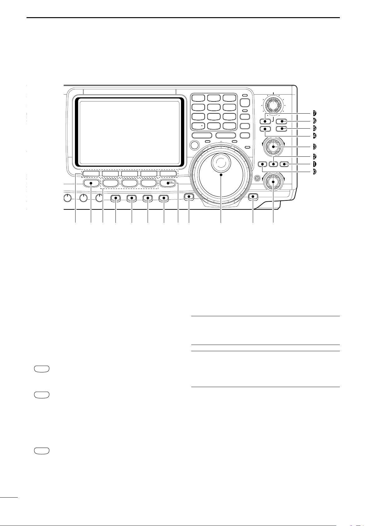
PANEL DESCRIPTION
■ Front panel
q POWER SWITCH [POWER]
➥ Push momentarily to turn power ON.
• Turn the optional DC power supply ON in advance.
➥ Push for 1 sec. to turn power OFF.
w TRANSMIT SWITCH [TRANSMIT]
Selects transmitting or receiving.
•The [TX] indicator lights red while transmitting and the
[RX] indicator lights green when the squelch is open.
e HEADPHONE JACK [PHONES]
Accepts headphones.
• Output power: 5 mW with an 8 Ω load.
•When headphones are connected, the internal speaker
or connected external speaker does not function.
r ELECTRONIC KEYER JACK [ELEC-KEY] (p. 14)
Accepts a paddle to activate the internal electronic
keyer for CW operation.
1
•Selection between the internal electronic keyer, bug-key
and straight key operation can be made in keyer set
mode. (p. 34)
•A straight key jack is separately available on the rear
panel. See [KEY] on p. 7.
•Keyer polarity (dot and dash) can be reversed in keyer
set mode. (p. 34)
•4-channel memory keyer is available for your convenience. (p. 30)
t MICROPHONE CONNECTOR [MIC]
Accepts the supplied or an optional microphone.
• See p. 101 for appropriate microphones.
• See p. 12 for microphone connector information.
y RF GAIN CONTROL/SQUELCH CONTROL
[RF/SQL] (outer control)
Adjusts the RF gain and squelch threshold level.
The squelch removes noise output from the speaker
(closed condition) when no signal is received.
•The squelch is particularly effective for FM. It is also
available for other modes.
•12 to 1 o’clock position is recommended for any setting
of the [RF/SQL] control.
•The control can be set as ‘Auto’ (RF gain control in SSB,
CW and RTTY; squelch control in AM and FM) or
squelch control (RF gain is fixed at maximum) in set
mode as follows. (p. 82)
• When setting as RF gain/squelch control
Page 15
PANEL DESCRIPTION
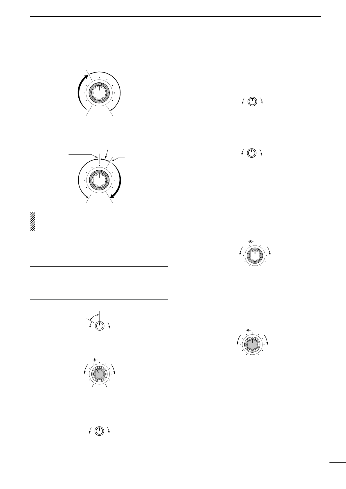
NR NOTCH
OFF
Decreases
Increases
NR NOTCH
Low frequency High frequency
Slow Fast
KEY SPEED
CW PITCH
IncreasesDecreases
RF PWR
IncreasesDecreases
AF RF/SQL
No audio output
Max. audio output
Decreases Increases
MIC GAIN
Recommended level for
an Icom microphone
IncreasesDecreases
Squelch is
open.
S-meter
squelch
S-meter squelch
threshold
Noise squelch
threshold
(FM mode)
Shallow Deep
Noise squelch (FM mode)
Minimum RF gain
Adjustable
range
Maximum
RF gain
1
•When functioning as RF gain control
(Squelch is fixed open; SSB, CW, RTTY only)
•When functioning as squelch control
(RF gain is fixed at maximum.)
While rotating the RF gain control, noise may be
heard. This comes from the DSP unit and does not
indicate an equipment malfunction.
u MIC GAIN CONTROL [MIC GAIN]
Adjusts microphone input gain.
•The transmit audio tone in SSB, AM and FM modes can
be adjusted in tone control set mode. (p. 89)
!0 CW PITCH CONTROL [CW PITCH] (p. 28)
Shifts the received CW audio pitch and monitored
CW audio pitch without changing the operating frequency.
•The pitch can be changed from 300 to 900 Hz in approx.
25 Hz steps.
!1 ELECTRONIC CW KEYER SPEED CONTROL
[KEY SPEED] (p. 28)
Adjusts the internal electronic CW keyer’s speed.
• 6 wpm (min.) to 60 wpm (max.) can be set.
!2 AUTO NOTCH/MANUAL NOTCH SWITCH
[A/NOTCH] (p. 53)
Toggles the notch function between manual and automatic when pushed.
•“NOTCH” appears when manual; “A NOTCH” appears
when automatic notch is selected.
!3 NOTCH CONTROL [NOTCH] (outer control; p. 53)
Adjusts the notch filter frequency to remove an in-
terfering signal.
✔
How to set the microphone gain.
Set the [MIC] control so that the ALC meter sometimes
swings during normal voice transmission in SSB mode.
Make sure that voice peak readings do not exceed the ALC
range brackets on the meter.
i AF CONTROL [AF] (inner control)
Varies the audio output level from the speaker.
o RF POWER CONTROL [RF PWR]
Continuously varies the RF output power from minimum (less than 5 W*) to maximum (100 W*).
* AM mode: less than 5 W to 40 W
!4 ANTENNA SELECTOR SWITCH [ANT] (p. 75)
Switches the antenna connector selection between
ANT1 and ANT2 when pushed.
!5 NOISE REDUCTION LEVEL CONTROL [NR]
(inner control; p. 53)
Adjusts the noise reduction level when the noise reduction is in use. Set for maximum readability.
ANTENNA TUNER SWITCH [TUNER] (pgs. 76, 77)
!6
➥ Turns the antenna tuner ON and OFF (bypass)
when pushed momentarily.
➥ Starts to tune the antenna manually when
pushed for 1 sec.
•When the tuner cannot tune the antenna, the tuning
circuit is bypassed automatically after 20 sec.
!7 NOISE REDUCTION SWITCH [NR] (p. 53)
Switches the noise reduction ON and OFF.
•“NR” appears while the noise reduction is activated.
2
Page 16
1
AM/FM
CW/RTTY
SSB
NR
A
/NOTCH
TUNER
ANT
HF/VHF TRANSCEIVER
NR
NOTCH
AF
MIC GAIN
RF PWR
CW PITCH
F 1
F 2F 3
F 4
F 5
XFC
MP-W
GENE
50
0
21
7
24
8
28
9
14
5
10
4
18
6
3.5
2
1. 8
1
7
3
144
ENT
MP-R
TX
RX
LOCK
TWIN PBT
M-CH
RIT
CLEAR
∂TX
RIT/∂TX
TS
SPLIT
PBTC
F-INP
A/B
V/M
MW
M-CL
KEY SPEED
P.AMP/ATT
NB
VOX/BK-IN
MONITOR
CALL
LOCK/
SPCH
RF/SQL
i746PRO
MENU
SSB
CW/RTTY
AM/FM
FILTER
#7
#6
#5
#4
#3
#2
#1
#0
!9 @0 @1!8 @2 @3 @4
@6@5 @7 @8 @9
PANEL DESCRIPTION
■ Front panel (continued)
!8 MULTI-FUNCTION SWITCHES [F1]–[F5]
!9 MENU SWITCH [MENU]
@0 MODE SWITCHES
➥Push to select the function indicated in the LCD
display above these switches. (p. 11)
•Functions vary depending on the operating mode.
➥Push to input a character for memory keyer pro-
gramming or memory name. (pgs. 31, 67)
Push to change the set of functions assigned to the
multi-function switches.
• Toggles between menu 1 (M1) and menu 2 (M2).
Selects the desired mode. (p. 23)
•Announces the selected mode when an optional UT-102
is installed. (p. 90)
➥ Selects USB and LSB mode alternately.
➥ Selects SSB data mode (USB-D, LSB-D)
when pushed for 1 sec. in SSB mode.
➥ Selects CW and RTTY mode alternately.
➥ Switches CW and CW-R (CW reverse)
mode when pushed for 1 sec. in CW
mode.
➥ Switches RTTY and RTTY-R (RTTY re-
verse)
mode when pushed for 1 sec. in
RTTY mode.
➥ Selects AM and FM mode alternately.
➥ Selects AM/FM data mode (AM-D, FM-D)
when pushed for 1 sec. in AM/FM mode.
@1 PREAMP/ATTENUATOR SWITCH [P.AMP/ATT]
(p. 48)
➥ Push momentarily to toggle between preamp-1
and preamp-2.
•“P.AMP1” activates for HF all bands.
•“P.AMP2” activates high-gain preamp for 24 MHz
band and above.
➥ Push for 1 sec. to toggle the attenuator function
ON and OFF.
✔
What is the preamp?
The preamp amplifies received signals in the front end circuit to improve the S/N ratio and sensitivity. Select “P.AMP1”
or “P.AMP2” when receiving weak signals.
✔
What is the attenuator?
The attenuator prevents a desired signal from distorting
when very strong signals are near the desired frequency, or
when very strong electric fields, such as from a broadcasting station, are near your location.
@2 NOISE BLANKER SWITCH [NB] (p. 51)
➥ Switches the noise blanker ON and OFF when
pushed. The noise blanker reduces pulse-type
noise such as that generated by automobile ignition systems. This function cannot be used for
FM, or non-pulse-type noise.
•“NB” appears while the noise blanker is activated.
➥ Enters the noise blanker level set mode when
pushed for 1 sec.
3
Page 17

PANEL DESCRIPTION
Low shift High shift
RIT/∂TX
1
@3 VOX/BREAK-IN SWITCH [VOX/BK-IN]
➥ In SSB, AM and FM modes, push momentarily to
turn the VOX function ON and OFF (p. 55); push
for 1 sec. to enter VOX set mode (p. 55).
➥ In CW mode, push momentarily to turn the semi
break-in, full break-in or break-in OFF (p. 56);
push for 1 sec. to enter break-in set mode (p. 56).
✔
What is the VOX function?
The VOX function (voice operated transmission) starts transmission without pushing the transmit switch or PTT switch
when you speak into the microphone; then, automatically returns to receive when you stop speaking.
✔
What is the break-in function?
Full break-in (QSK) activates the receiver between transmitted dots and dashes. This is useful when operating in nets,
or during DX pileups and during contests, when “fast exchanges” are common.
@4 MONITOR SWITCH [MONITOR] (p. 57)
➥ Monitors your transmitted signal.
➥ Enters monitor set mode when pushed for 1 sec.
@5 FILTER SWITCH [FILTER] (p. 50)
➥ Selects one of 3 IF filter settings.
➥ Enters the filter set mode when pushed for 1 sec.
@6 CALL SWITCH [CALL] (p. 64)
Selects the call channel when pushed momentarily.
@7 TUNING DIAL (p. 21)
Changes the displayed frequency, selects set mode
items, etc.
#0 RIT SWITCH [RIT] (p. 48)
➥
Turns the RIT function ON and OFF when pushed.
• Use the [RIT/∂TX] control to vary the RIT frequency.
➥ Adds the RIT shift frequency to the operating fre-
quency when pushed for 1 sec.
✔
What is the RIT function?
The RIT (Receiver Incremental Tuning) shifts the receive frequency without shifting the transmit frequency.
This is useful for fine tuning stations calling you on an off-frequency or when you prefer to listen to slightly differentsounding voice characteristics, etc.
#1 CLEAR SWITCH [CLEAR] (pgs. 48, 57)
Clears the RIT/∂TX shift frequency when pushed
for 1 sec.
•Can be cleared instantly when [CLEAR] is pushed if the
Quick RIT Clear is set to ON (p. 86).
#2∂∂TX SWITCH [∂∂TX] (p. 57)
➥ Turns the ∂TX function ON and OFF when
pushed.
•Use the [RIT/∂TX] control to vary the ∂TX frequency.
➥ Adds the ∂TX shift frequency to the operating
frequency when pushed for 1 sec.
✔
What is the ∂∂TX function?
The ∂TX shifts the transmit frequency without shifting the receive frequency. This is useful for simple split frequency operation in CW, etc.
#3 MEMORY CHANNEL SELECTOR [M-CH] (p. 62)
Select a memory channel.
•Rotate clockwise to increase the memory channel; rotate counterclockwise to decrease the memory channel.
@8
LOCK/SPEECH SWITCH [LOCK/SPCH]
➥ Push momentarily to toggle the dial lock function
ON and OFF. (p. 53)
➥ Pushing for 1 sec. announces the selected read-
out frequency and S-meter indication when an
optional UT-102 is installed. (p. 90)
@9 RIT/∂∂TX CONTROL [RIT/∂∂TX] (pgs. 48, 57)
Shifts the receive and/or transmit frequency without
changing the transmit and/or receive frequency
while the RIT and/or ∂TX functions are ON.
•Rotate the control clockwise to increase the frequency,
or rotate the control counterclockwise to decrease the
frequency.
• The shift frequency range is ±9.99 kHz in 10 Hz steps.
#4 VFO/MEMORY SWITCH [VFO/MEMO]
➥ Switches the selected readout operating mode
between the VFO mode and memory mode when
pushed. (pgs. 20, 62)
➥ Transfers the memory contents to VFO when
pushed for 1 sec. (p. 65)
#5 MEMORY CLEAR SWITCH [M-CL] (p. 63)
Clears the selected readout memory channel contents when pushed for 1 sec. in memory mode.
• The channel becomes a blank channel.
• This switch does not function in VFO mode.
#6 MEMORY WRITE SWITCH [MW] (p. 63)
Stores the selected readout frequency and operating mode into the displayed memory channel when
pushed for 1 sec.
•This function is available both in VFO and memory
modes.
#7 PBT CLEAR SWITCH [PBTC] (p. 52)
Clears the PBT settings when pushed for 1 sec.
4
Page 18
Quick tuning indicator
1
A
/NOTCH
NER
ANT
HF/VHF TRANSCEIVER
NOTCH
MIC GAIN
RF PWR
CW PITCH
F 1
F 2F 3
F 4
F 5
XFC
MP-W
GENE
50
0
21
7
24
8
28
9
14
5
10
4
18
6
3.5
2
1. 8
1
7
3
144
ENT
MP-R
TX
RX
LOCK
TWIN PBT
M-CH
RIT
CLEAR
∂TX
RIT/∂TX
TS
SPLIT
PBTC
F-INP
A/B
V/M
MW
M-CL
KEY SPEED
P.AMP/ATT
NB
VOX/BK-IN
MONITOR
CALL
LOCK/
SPCH
RF/SQL
MENU
SSB
CW/RTTY
AM/FM
FILTER
$7
$4
$5
$6
$3
$2
$1
$0
#9
#8
%2
%0 $9 $8%1
PANEL DESCRIPTION
■ Front panel (continued)
#8 TRANSMIT FREQUENCY CHECK SWITCH [XFC]
(pgs. 45, 48)
Monitors the transmit frequency when pushed and
held.
•While pushing this switch, the transmit frequency can be
changed with the tuning dial, keypad or memo pad.
•When the split lock function is turned ON, pushing [XFC]
cancels the dial lock function. (p. 60)
#9 MEMO PAD-WRITE SWITCH [MP-W] (p. 68)
Programs the selected readout frequency and operating mode into a memo pad.
•The 5 most recent entries remain in memo pads.
•The transmit frequency is programmed when pushed to-
gether with [XFC].
•The memo pad capacity can be expanded from 5 to 10
in set mode for your convenience. (p. 85)
$0 TRANSMIT INDICATOR [TX]
Lights red while transmitting.
$1 MEMO PAD-READ SWITCH [MP-R] (p. 68)
Each push calls up a frequency and operating
mode in a memo pad. The 5 (or 10) most recently
programmed frequencies and operating modes can
be recalled, starting from the most recent.
•The memo pad capacity can be expanded from 5 to 10
in set mode for your convenience. (p. 85)
$2 RECEIVE INDICATOR [RX]
Lights green while receiving a signal and when the
squelch is open.
$3 LOCK INDICATOR [LOCK] (p. 53)
Lights when the dial lock function is activated.
5
$4 QUICK TUNING SWITCH [TS] (p. 21)
➥ Turns the quick tuning step ON and OFF.
•While the quick tuning indicator is displayed, the frequency can be changed in programmed kHz steps.
•0.1, 1, 5, 9, 10, 12.5, 20 and 25 kHz quick tuning
steps are available.
➥ While the quick tuning step is OFF, turns the 1 Hz
step ON and OFF when pushed for 1 sec.
•1 Hz indication appears, and the frequency can be
changed in 1 Hz steps.
➥ While the quick tuning step is ON, enters the
quick tuning step set mode when pushed for
1 sec.
$5 VFO SELECT SWITCH [A/B] (p. 20)
➥ Push to toggle between VFO A and VFO B.
➥ Push for 1 sec. to equalize the frequency and op-
erating mode of the two VFO’s.
Page 19
PANEL DESCRIPTION
PBT1
PBT2
TWIN PBT
Low cut High cutCenter
TWIN PBT TWIN PBT TWIN PBT
– +
1
$6 SPLIT SWITCH [SPLIT]
➥ Turns the split function ON and OFF when
pushed.(p. 59)
➥ Turns the quick split function ON, when pushed
for 1 sec. (p. 60)
•The offset frequency is shifted from the displayed frequency.
•The quick split function can be turned OFF using set
mode. (p. 83)
➥ Turns the split function ON and sets the transmit
frequency after inputting an offset frequency with
the keypad (±4 MHz in 1 kHz steps; p. 59).
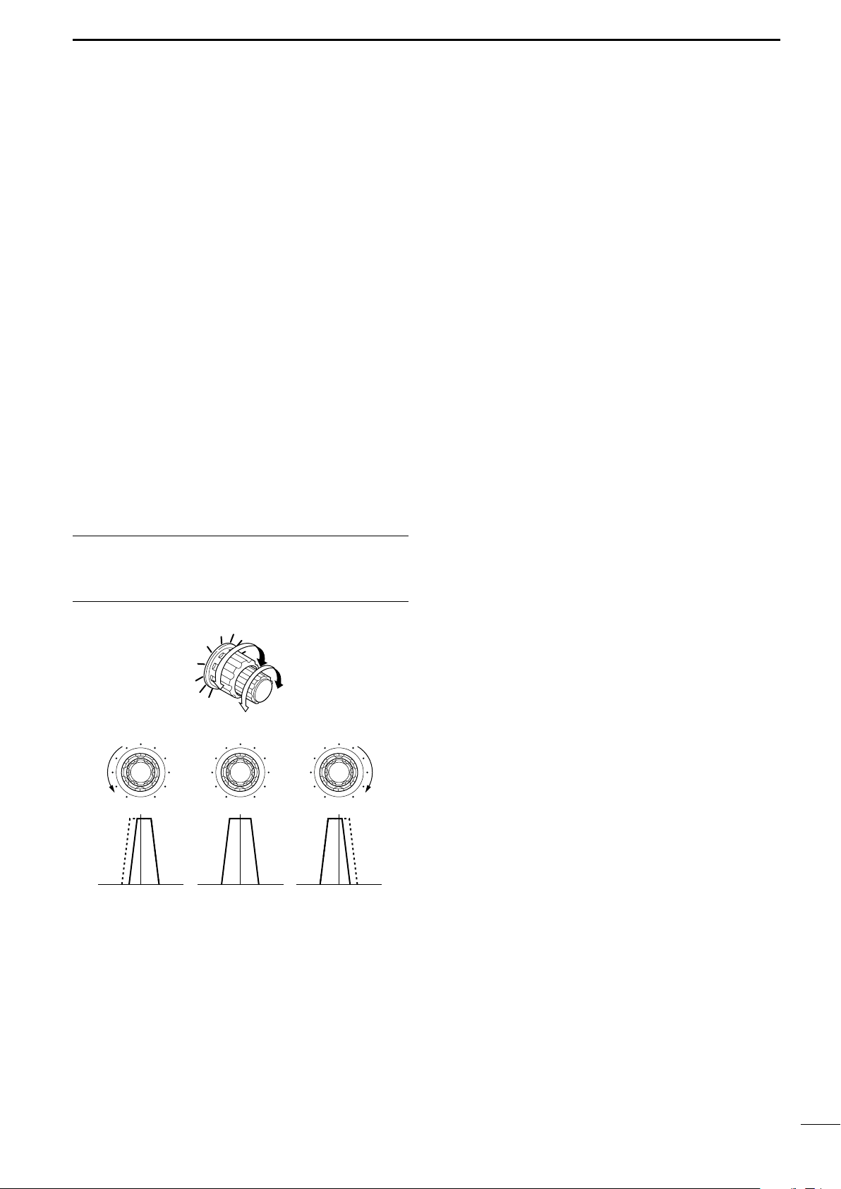
$7 PASSBAND TUNING CONTROLS [TWIN PBT]
Adjust the receiver’s “passband width” of the DSP
filter. (p. 52)
•Passband width and shift frequency are displayed in the
multi-function switch indicator.
•Push [PBTC] for 1 sec. to clear the settings when not in
use.
•Variable range is set to half of the IF filter passband
width. 25 Hz steps and 50 Hz steps are available.
•These controls function as an IF shift control while in AM
mode and when the RTTY filter is turned ON. Only the
inner control may function in this case.
✔
What is the PBT control?
General PBT function electronically narrows the IF passband
width to reject interference. This transceiver uses the DSP
circuit for the PBT function.
%1 KEYPAD
➥ Pushing a key selects the operating band.
•[GENE • ] selects the general coverage band.
➥ Pushing the same key 2 or 3 times calls up other
stacked frequencies and modes in the band.
(p. 19)
•Icom’s triple band stacking register memorizes 3 frequencies in each band.
➥ After pushing [F-INP], enter a keyed frequency.
Pushing [144 ENT] is necessary at the end.
(p. 22)
•e.g. to enter 14.195 MHz, push [F-INP] [1.81] [104]
[GENE • ] [1.8
1
] [289] [145] [144 ENT].
%2 LCD FUNCTION DISPLAY
(See pgs. 9, 10 for details.)
Shows the operating frequency, function switch
menus, band scope screen, memory name screen,
set mode settings, etc.
$8 SPLIT INDICATOR (p. 59)
Lights during split operation.
$9 FREQUENCY INPUT SWITCH [F-INP] (p. 22)
Push to toggle keypad input between frequency and
band.
• The frequency input indicator lights when frequency input is selected for the keypad.
%0 FREQUENCY INPUT INDICATOR (p. 22)
Lights when frequency input from the keypad is enabled.
6
Page 20
!5 !3 t
r
!2 !1 !0 oi uy
qwe
!4
1
(+)
(_)
Rear panel view
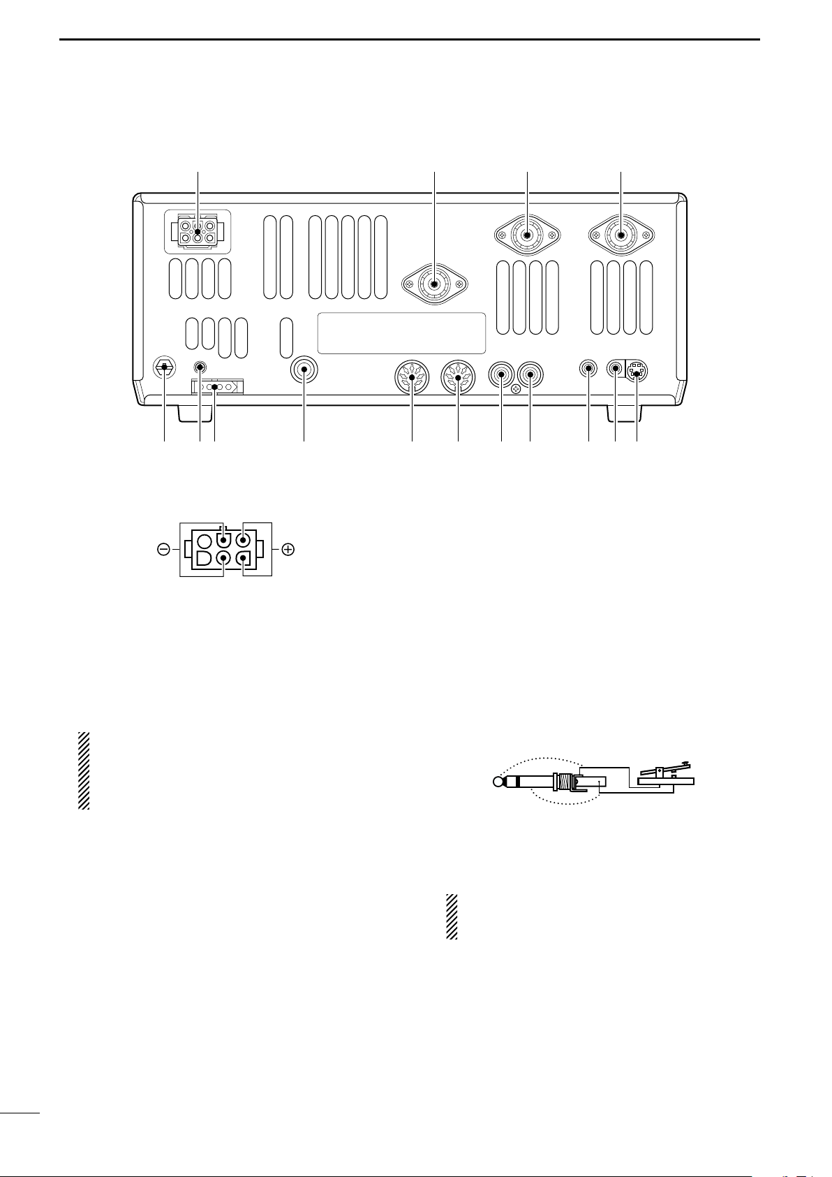
PANEL DESCRIPTION
■ Rear panel
q DC POWER SOCKET [DC 13.8V] (pgs. 14, 16)
Accepts 13.8 V DC through the supplied DC power
cable (OPC-025D).
w ANTENNA CONNECTOR [ANT 144MHz]
e ANTENNA CONNECTOR 2 [ANT2]
r ANTENNA CONNECTOR 1 [ANT1]
(pgs. 14, 15, 17, 75)
Accepts a 50 Ω antenna with a PL-259 connector.
•[ANT 144MHz] for 144 MHz (2 m) band only; [ANT1] and
[ANT2] for both HF and 50 MHz (6 m) bands antennas.
When using an optional AH-4 HF/50 MHz AUTO-
MATIC ANTENNA TUNER
, connect it to the [ANT1]
connector. The internal antenna tuner activates
for [ANT2] and deactivates for [ANT1] when connecting the AH-4.
t DATA SOCKET [DATA] (pgs. 15, 78)
Connects a TNC (Terminal Node Controller), etc. for
data communications.
• See p. 8 for connector information.
y
EXTERNAL SPEAKER JACK [EXT SP] (pgs. 15, 101)
Accepts a 4–8 Ω speaker.
u
CI-V REMOTE CONTROL JACK [REMOTE] (p. 95)
➥ Designed for use with a personal computer for re-
mote control of the transceiver functions.
➥ Used for transceive operation with another Icom
CI-V transceiver or receiver.
i SEND CONTROL JACK [SEND] (p. 17)
Goes to ground while transmitting to control external equipment such as a linear amplifier.
• Max. control level: 16 V DC/0.5 A
CAUTION: Be sure the linear amplifiers keying cir-
7
cuit control voltage is compatible to the IC-746PRO,
before connecting to [SEND].
o ALC INPUT JACK [ALC] (p. 17)
Connects to the ALC output jack of a non-Icom linear amplifier.
!0 ACCESSORY SOCKET 2 [ACC(2)]
!1 ACCESSORY SOCKET 1 [ACC(1)]
Enables connection of external equipment such as
a linear amplifier, an automatic antenna selector/
tuner, TNC for data communications, etc.
• See p. 8 for socket information.
!2 STRAIGHT KEY JACK [KEY] (p. 14)
Accepts a straight key or external electronic keyer
with 1⁄4 inch standard plug.
•[ELEC-KEY] on the front panel can be used for a straight
key or external electronic keyer. Deactivate the internal
electronic keyer in keyer set mode. (p. 34)
!3 TUNER CONTROL SOCKET [TUNER]
(pgs. 15, 77)
Accepts the control cable from an optional AH-4
HF/50 MHz AUTOMATIC ANTENNA TUNER.
If you use an external electronic keyer, make
sure the voltage retained by the keyer is less
than 0.4 V when the key is ON.
!4 CALIBRATION POT [CAL] (p. 94)
This is used for frequency calibration.
•The transceiver has been adjusted and calibrated thoroughly at the factory. Under normal circumstances, the
frequency does not need to be re-calibrated.
!5 GROUND TERMINAL [GND] (pgs. 13, 14)
Connect this terminal to a ground to prevent electrical shocks, TVI, BCI and other problems.
Page 21
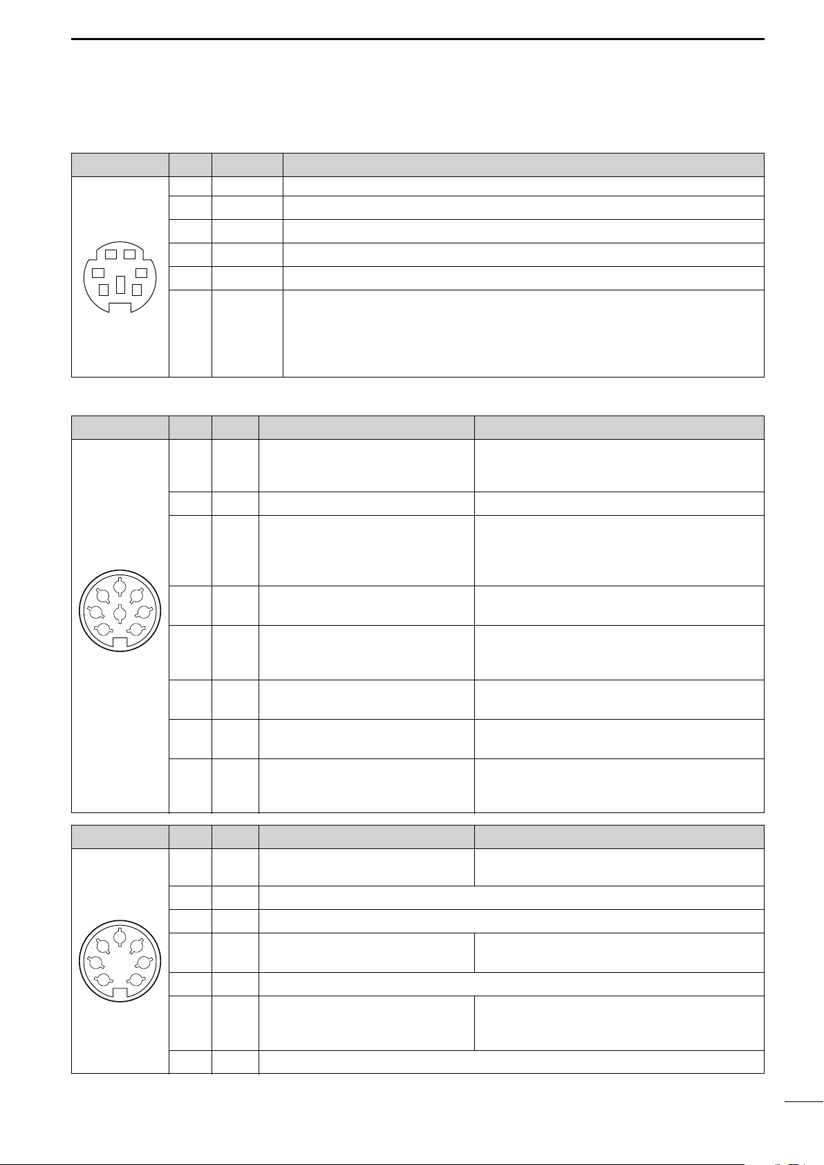
D DATA SOCKET
PANEL DESCRIPTION
1
DATA
PIN No.
1 DATA IN Input terminal for data transmit. (1200 bps: AFSK/9600 bps: G3RUH, GMSK)
2 GND Common ground for DATA IN, DATA OUT and AF OUT.
3 PTT P PTT terminal for packet operation. Connect ground to transmit data.
12
34
56
Rear panel view
4 DATA OUT Data out terminal for 9600 bps operation only.
5 AF OUT Data out terminal for 1200 bps operation only.
6 P SQL •To avoid unnecessary TNC transmission, connect squelch to the TNC to inhibit trans-
D ACC SOCKETS
ACC (1)
2
4
1
8
6
Rear panel view
PIN No.
1 RTTY Controls RTTY keying “Low” level : Less than 0.6 V
2 GND Connects to ground. Connected in parallel with ACC(2) pin 2.
3
5
3
7
4 MOD
5 AF Fixed, regardless of [AF] position in
NAME DESCRIPTION
Squelch out terminal. Becomes high (+8 V) when the transceiver receives a signal
which opens the squelch.
mission when receiving signals.
• Keep audio output at a normal level, otherwise a “P SQL”signal will not be output.
NAME DESCRIPTION SPECIFICATIONS
“High” level : More than 2.4 V
Output current : Less than 2 mA
Ground level : –0.5 V to 0.8 V
Output current : Less than 20 mA
Input current (Tx) : Less than 200 mA
Connected in parallel with ACC(2) pin 3.
HSEND
Input/output pin.
(HF/50 MHz only)
Goes to ground when transmitting.
When grounded, transmits.
Modulator input. Input impedance : 10 kΩ
Connects to a modulator. Input level : Approx. 100 mV rms
AF detector output.
default settings. (see notes below)
Output impedance : 4.7 kΩ
Output level : 100–300 mV rms
ACC (2)
2
4
5
1
Rear panel view
3
6
7
6 SQLS
7 13.8 V 13.8 V output when power is ON.
Squelch output. SQL open : Less than 0.3 V/5 mA
Goes to ground when squelch opens.
SQL closed : More than 6.0 V/100 µA
Output current : Max. 1 A
Connected in parallel with ACC(2) pin 7.
Control voltage : –4 V to 0 V
8 ALC ALC voltage input. Input impedance : More than 10 kΩ
Connected in parallel with ACC(2) pin 5.
PIN No.
NAME DESCRIPTION SPECIFICATIONS
1 8 V Regulated 8 V output.
Output voltage : 8 V ±0.3 V
Output current : Less than 10 mA
2 GND Same as ACC(1) pin 2.
HSEND
3
4 BAND
Band voltage output.
(Varies with amateur band)
Same as ACC(1) pin 3.
Output voltage : 0 to 8.0 V
5 ALC Same as ACC (1) pin 8.
Input/output pin (144 MHz only) Ground level : –0.5 V to +0.8 V
6
VSEND
Goes to ground when transmitting. Output current : Less than 20 mA
When grounded, transmits. Input current (Tx) : Less than 200 mA
7
13.8 V
Same as ACC(1) pin 7.
8
Page 22
1
q
w
t
!0
o
i
u
y
!1!2!3!4
e
r
PANEL DESCRIPTION
■ LCD display
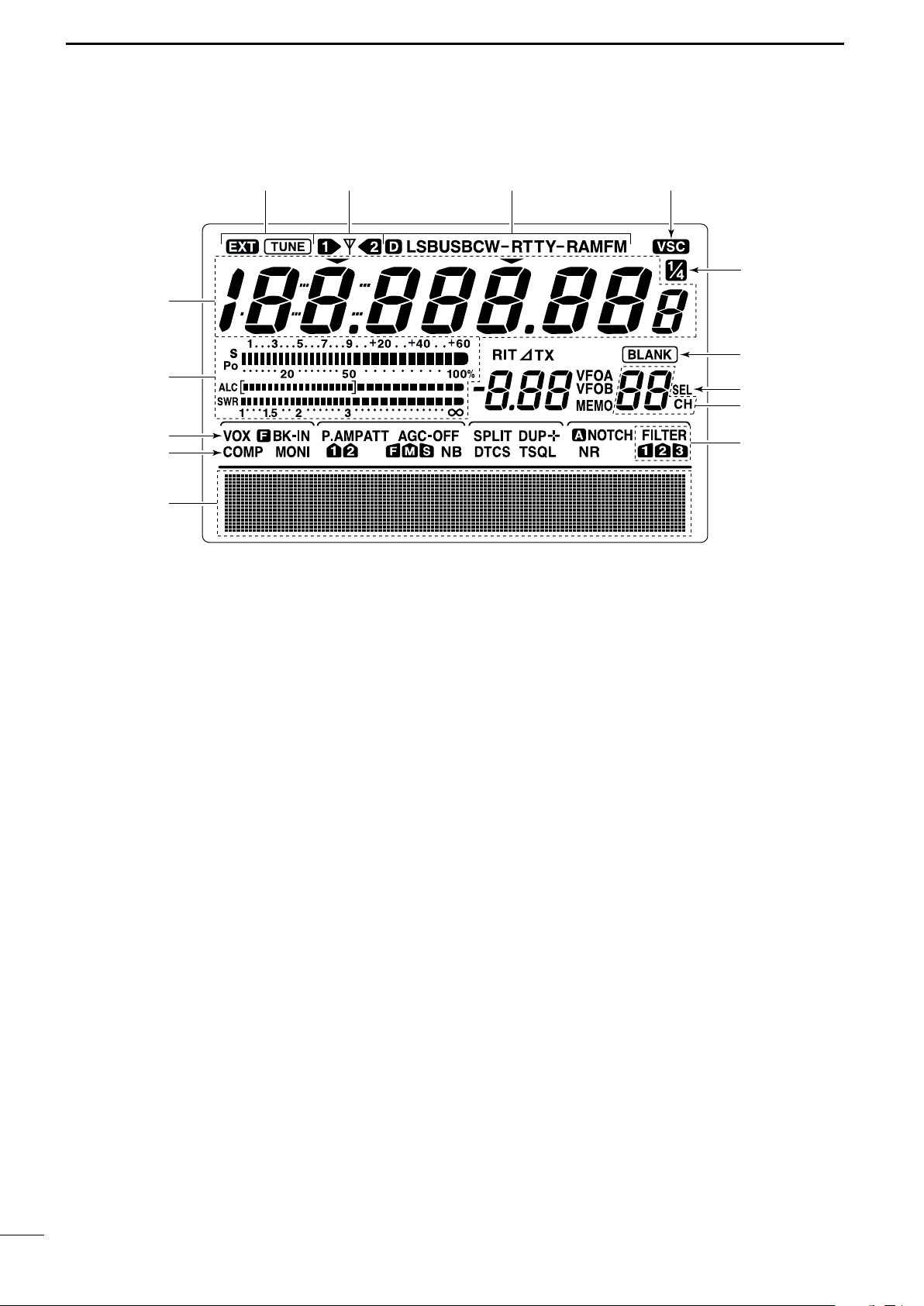
q FREQUENCY READOUTS
Shows the operating frequency.
w MULTI-FUNCTION METER INDICATION
➥ Shows receiving signal strength, etc. during re-
ceive.
➥ Shows transmit output power, ALC and SWR dur-
ing transmit.
e VOX INDICATOR (p. 55)
Appears when the VOX function is activated.
r
MICROPHONE COMPRESSOR INDICATOR (p. 58)
Appears when the microphone compressor is activated.
t MULTI-FUNCTION SWITCH INDICATOR (p. 11)
Indicates the functions assigned to the multi-function switches ([F1]–[F5]).
y DSP FILTER INDICATOR (p. 50)
Shows the selected IF filter.
u MEMORY CHANNEL READOUTS (p. 62)
Shows the selected memory channel.
i SELECT MEMORY CHANNEL INDICATOR (p. 72)
Appears when the selected memory channel is set
as a select memory channel.
o BLANK MEMORY INDICATOR (p. 62)
Appears when the selected memory channel is
blank.
!01⁄4 TUNING DIAL SPEED INDICATOR (p. 21)
Appears when the tuning dial speed is set so that
one rotation is equal to 1⁄4 of the normal rotation.
!1 VOICE SQUELCH CONTROL INDICATOR (p. 54)
Appears during VSC (Voice Squelch Control) function is activated.
!2 MODE INDICATORS (p. 23)
Shows the selected operating mode.
•“D” appears when SSB data, AM data or FM data mode
is selected.
!3 ANTENNA INDICATOR (p. 75)
Indicates which antenna connector is used for
HF/50 MHz.
!4 ANTENNA TUNER INDICATORS (pgs. 76, 77)
➥ “TUNE” appears when the antenna tuner is ON;
“TUNE” appears and flashes during tuning.
➥ “EXT” appears when the optional AH-4 external
antenna tuner is connected to [ANT1].
9
Page 23
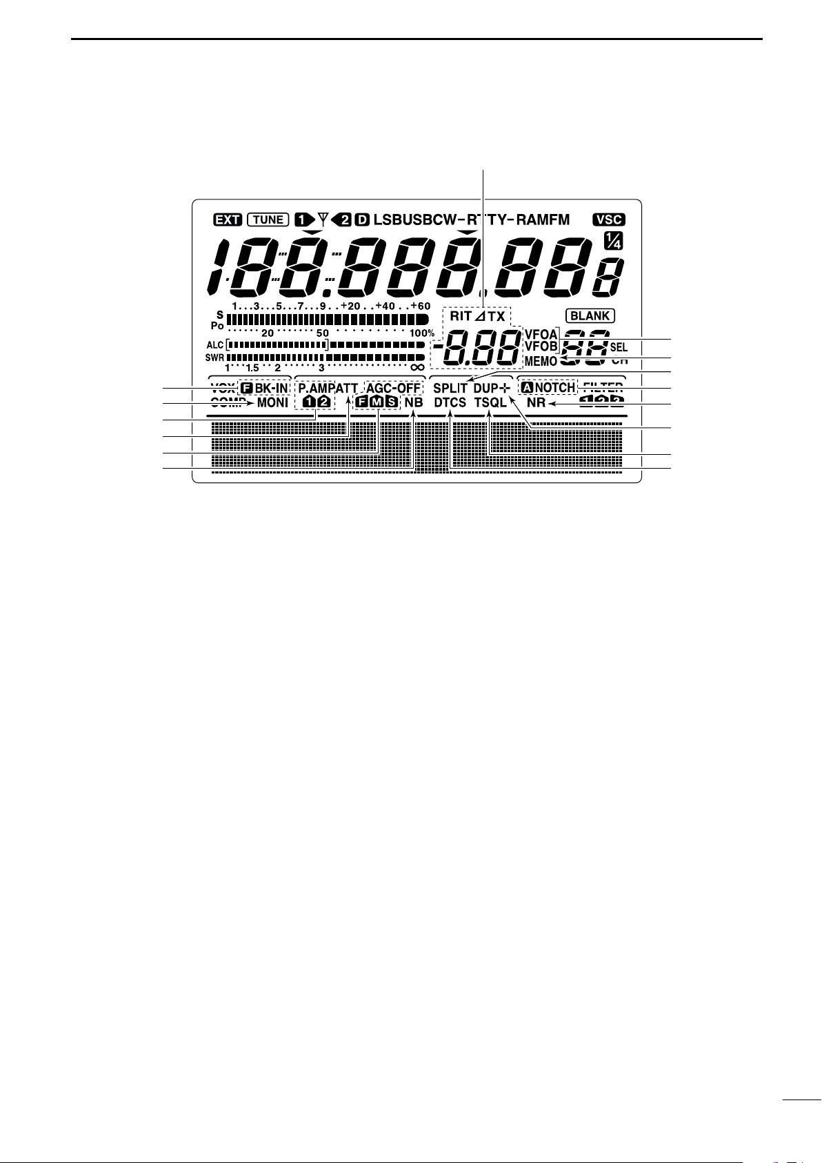
■ LCD display (continued)
!7
!8
!9
@0
@7
@6
@5
@4
@2
@3
@1
@9
!5
!6
@8
PANEL DESCRIPTION
1
!5 BREAK-IN INDICATORS (p. 56)
➥ “FBK-IN” appears when the full break-in function
is activated.
➥ “BK-IN” appears when the semi break-in function
is activated.
!6 MONITOR INDICATOR (p. 57)
Appears when the monitor function is activated.
!7 PREAMP INDICATORS (p. 48)
Appears when the preamp is activated.
!8 ATTENUATOR INDICATOR (p. 48)
Appears when the attenuator is activated.
!9 AGC INDICATORS (p. 49)
Shows the selected AGC time constant.
•“F” for AGC fast; “M” for AGC middle; “S” for AGC
slow; “-OFF” for AGC OFF.
@0 NOISE BLANKER INDICATOR (p. 51)
Appears when the noise blanker is activated.
@1 DTCS INDICATOR (p. 43)
Appears during DTCS operation.
@2 TONE SQUELCH INDICATORS
➥ “T” appears when the repeater tone is activated.
(p. 44)
➥ “TSQL” appears during tone squelch operation.
(p. 42)
@3 DUPLEX INDICATOR (p. 44)
“DUP–” or “DUP+” appears during repeater operation.
@4 NOISE REDUCTION INDICATOR (p. 53)
Appears when the noise reduction is activated.
@5 NOTCH INDICATORS (p. 53)
➥ “NOTCH” appears when the manual notch func-
tion is activated.
➥ “ANOTCH” appears when the automatic notch
function is activated.
@6 SPLIT INDICATOR (pgs. 59, 60)
Appears during split operation.
@7 MEMORY INDICATOR (p. 62)
Appears during memory mode.
@8 VFO INDICATORS (p. 20)
Indicates whether VFO A or VFO B is selected.
@9 RIT/∂∂TX INDICATORS (pgs. 48, 57)
Appears during RIT or ∂TX operation and indicates
the frequency offset.
10
Page 24
1
F 5
VSC
F 4
TCN
F 3
SWR
F 2
MEM
F 1
SCN
F 1
F 2F 3
F 4
F 5
SCN MEM SWR TCN VSC
PANEL DESCRIPTION
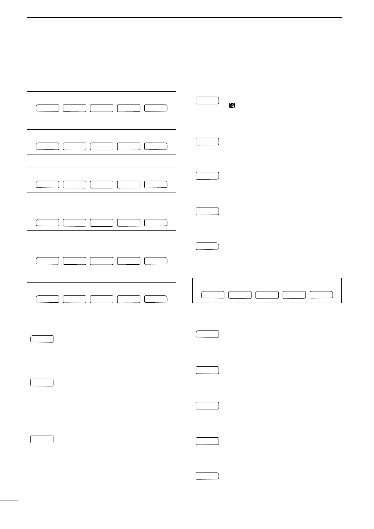
■ Multi function switches
DD
M1 FUNCTIONS
During SSB operation
AGC DUP CMP TBW SCP
F 1
F 2F 3
F 4
1
⁄4 TUNING FUNCTION (p. 21)
1/4
F 3
F 5
Push to turn the 1⁄4 tuning function
ON/OFF.
•“ ” indicator appears when the 1⁄
function is ON.
4 tuning
During SSB data operation
AGC DUP 1/4 SCP
F 1
F 2F 3
F 4
During CW operation
AGC DUP 1/4 KEY SCP
F 1
F 2F 3
F 4
During RTTY operation
AGC DUP 1/4 RTY SCP
F 1
F 2F 3
F 4
During AM operation
AGC DUP CMP SCP
F 1
F 2F 3
F 4
During FM operation
AGC DUP CMP TON SCP
F 1
F 2F 3
F 4
TRANSMISSION BANDWIDTH (p. 58)
TBW
F 5
F 4
Push to select the transmission bandwidth.
•Bandwidth is selectable from narrow, middle
and wide.
MEMORY KEYER MENU (p. 29)
KEY
F 4
F 5
Push to select the memory keyer or keyer
send menu, depending on the KEYER
1st Menu setting in the set mode (p. 86).
RTTY MENU (p. 36)
RTY
F 4
F 5
Push to select the RTTY menu.
BAND SCOPE FUNCTION (p. 47)
SCP
F 5
F 5
DD
M2 FUNCTIONS
F 5
Push to select the band scope screen.
AGC (p. 49)
AGC
➥ Push momentarily to change the time
F 1
constant of the AGC circuit.
➥ Push for 1 sec. to enter to the AGC set
mode.
DUPLEX (p. 44)
DUP
➥ Push momentarily to select the duplex di-
F 2
rection or turn the function OFF.
•“DUP–” or “DUP+” indicator appears during
duplex operation.
➥ Push for 1 sec. to turn the one-touch re-
peater function ON/OFF.
SPEECH COMPRESSOR (p. 58)
CMP
➥ Push momentarily to turn the speech
F 3
compressor function ON/OFF.
•“COMP” indicator appears when the speech
compressor is ON.
➥ Push for 1 sec. to enter to the compres-
sor set mode.
SCAN MENU (p. 70)
Push to select the scan menu.
MEMORY NAME MENU (p. 67)
Push to select the memory name screen.
SWR GRAPH FUNCTION (p. 61)
Push to indicate the SWR graph screen.
TONE CONTROL SET MODE (p. 89)
Push to enter the audio tone set mode.
VSC FUNCTION (p. 54)
Push to turn the VSC (Voice Squelch Control) function ON and OFF.
11
Page 25
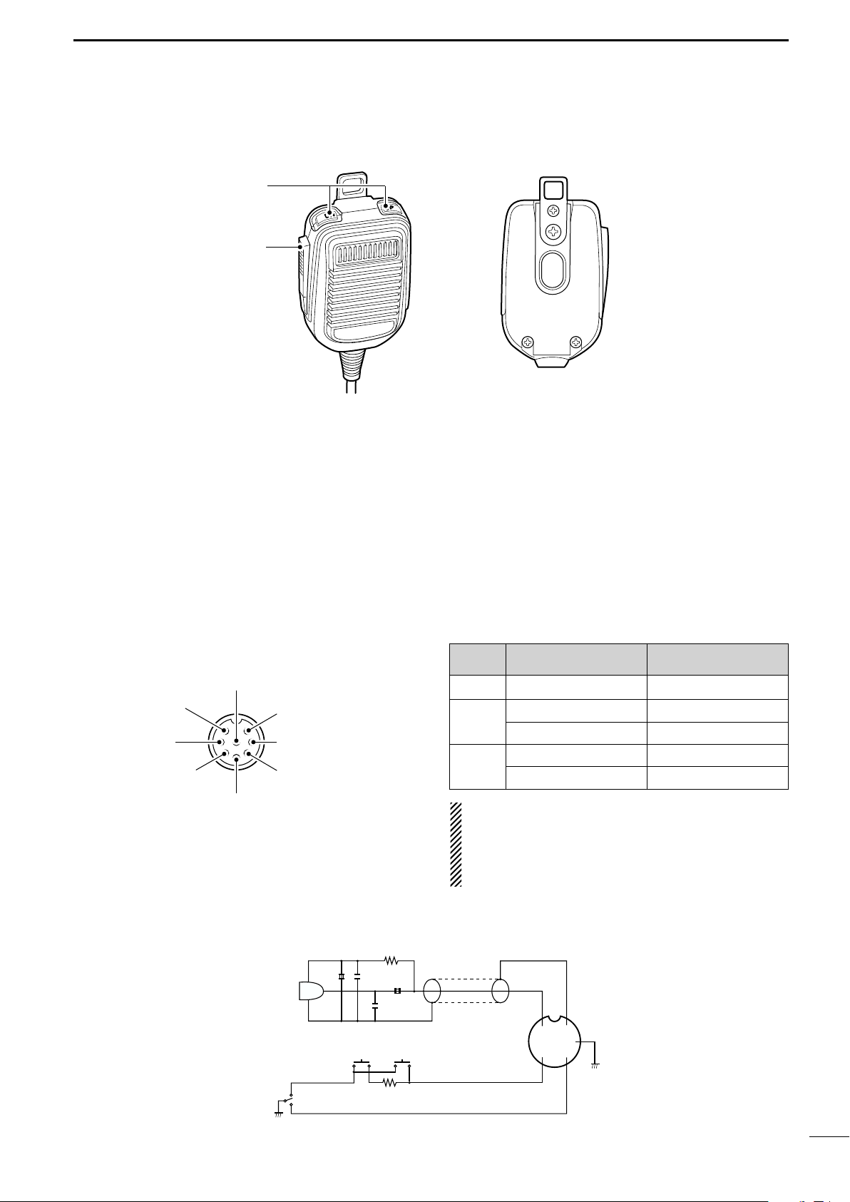
■ Microphone (HM-36)
y GND (PTT ground)
t PTT
r Main readout squelch switch
q Microphone input
w +8 V DC output
e Frequency up/down
u GND
(Microphone ground)
i Main readout AF output
(varies with [AF]/[BAL])
q
w
PANEL DESCRIPTION
1
q UP/DOWN SWITCHES [UP]/[DN]
Change the selected readout frequency or memory
channel.
•Continuous pushing changes the frequency or memory
channel number continuously.
•While pushing [XFC], the transmit readout frequency can
be controlled while in spilt frequency operation.
•The [UP]/[DN] switch can simulate a key paddle. Preset
in the keyer set mode. (p. 34)
•MICROPHONE CONNECTOR
(Front panel view)
w PTT SWITCH
Push and hold to transmit; release to receive.
[MIC]
Pin No.
w +8 V DC output Max. 10 mA
e
r
FUNCTION DESCRIPTION
Frequency up Ground
Frequency down Ground through 470 Ω
Squelch open “Low” level
Squelch closed “High” level
CAUTION: DO NOT short pin 2 to ground as this
can damage the internal 8 V regulator.
NOTE: DC voltage is applied to pin 1 for microphone operation. Take care when using a non-Icom
microphone.
• HM-36 SCHEMATIC DIAGRAM
MIC
ELEMENT
PTT
MICROPHONE
10µ
RECEIVE
TRANSMIT
+
2k
4700p
0.33µ
4700p
DOWN UP
470
MICROPHONE CABLE MICROPHONE PLUG
+
q
i
w
ert
u
y
12
Page 26
2
INSTALLATION AND CONNECTIONS
■ Unpacking
After unpacking, immediately report any damage to the
delivering carrier or dealer. Keep the shipping cartons.
For a description and a diagram of accessory equipment included with the IC-746PRO, see ‘Supplied accessories’ on p. ii of this manual.
■ Selecting a location
Select a location for the transceiver that allows adequate air circulation, free from extreme heat, cold, or
vibrations, and away from TV sets, TV antenna elements, radios and other electromagnetic sources.
The base of the transceiver has an adjustable stand
for desktop use. Set the stand to one of two angles depending on your operating conditions.
■ Antenna connection
For radio communications, the antenna is of critical importance, along with output power and sensitivity. Select antenna(s), such as a well-matched 50 Ω antenna,
and feedline. 1.5:1 or better of Voltage Standing Wave
Ratio (VSWR) is recommended for your desired band.
Of course, the transmission line should be a coaxial
cable.
When using 1 antenna, use the [ANT1] connector.
CAUTION: Protect your transceiver from lightning
by using a lightning arrestor.
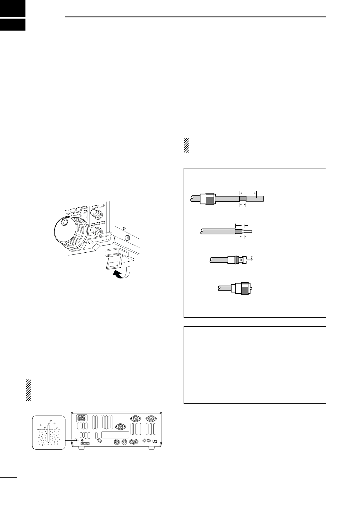
PL-259 CONNECTOR INSTALLATION EXAMPLE
q
Coupling ring
w
e
30 mm
10 mm (soft solder)
10 mm
Soft
solder
1–2 mm
solder solder
Slide the coupling ring
down. Strip the cable
jacket and soft solder.
Strip the cable as
shown at left. Soft solder the center conductor.
Slide the connector
body on and solder it.
■ Grounding
To prevent electrical shock, television interference
(TVI), broadcast interference (BCI) and other problems, ground the transceiver through the GROUND
terminal on the rear panel.
For best results, connect a heavy gauge wire or strap
to a long earth-sunk copper rod. Make the distance between the [GND] terminal and ground as short as possible.
R WARNING: NEVER connect the [GND]
terminal to a gas or electric pipe, since the connection could cause an explosion or electric shock.
r
30 mm ≈9⁄8
in 10 mm ≈
Screw the coupling
ring onto the
connector body.
3
⁄8
in 1–2 mm ≈
1
⁄16
Antenna SWR
Each antenna is tuned for a specified frequency
range and SWR may be increased out-of-range.
When the SWR is higher than approx. 2.0:1, the
transceiver’s power drops to protect the final transistor. In this case, an antenna tuner is useful to match
the transceiver and antenna. Low SWR allows full
power for transmitting even when using the antenna
tuner. The IC-746PRO has an SWR meter to monitor the antenna SWR continuously.
in
13
Page 27
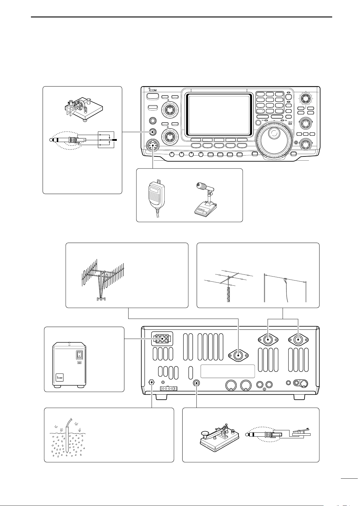
■ Required connections
i746PRO
POWER
F 1
MENU SSB
F 2
CW/RTTY
F 3
AM/FM
F 4
FILTER
F 5
XFC
MP-W
GENE
50
MP-R
0
21724828
9
10
4145186
1.8
1
3.5
2
7
3
144
ENT
TS
A/B
SPLIT
F-INP
V/M
M-CL
PBTC
MW
TWIN PBT
M-CH
LOCK/
SPCH
∂TXRIT
CLEAR
RIT/∂TX
CALL
MONITOR
VOX/BK-IN
NB
P.AMP/ATT
KEY SPEED
CW PITCH
RF PWR
MIC GAIN
HF/VHF TRANSCEIVER
TRANSMIT
PHONES
ELEC-KEY
MIC
TUNER
ANT
NR
NOTCH
AF
RF/SQL
NR
A/NOTCH
CW KEY
MICROPHONES (p. 101)
A straight key can be used
when the internal electronic
keyer is turned OFF in keyer
set mode. (p. 34)
HM-36 SM-20
(optional)
(dot)
(com)
(dash)
GROUND (p. 13)
Use the heaviest gauge wire or
strap available and make the
connection as short as possible.
Grounding prevents electrical
shocks, TVI and other problems.
ANTENNA 1, 2 (pgs. 13, 75)
[Example]: ANT1 for 1.8–18 MHz bands
ANT2 for 21–50 MHz bands
DC POWER SUPPLY
STRAIGHT KEY
PS-125
(Optional)
144 MHz ANTENNA (pgs. 13, 75)
Connect a VHF
(60–144 MHz)
antenna;
impedance: 50 Ω.
(+)
(_)
• Front panel
INSTALLATION AND CONNECTIONS
2
• Rear panel
14
Page 28
2
POWER
TRANSMIT
PHONES
ELEC-KEY
MIC
NR
A
/NOTCH
TUNER
ANT
HF/VHF TRANSCEIVER
NR
NOTCH
AF
MIC GAIN
RF PWR
CW PITCH
F 1
F 2F 3F 4F 5
XFC
MP-W
GENE
50
0
21
7
24
8
28
9
14
5
10
4
18
6
3.5
2
1.8
1
7
3
144
ENT
MP-R
TX
RX
LOCK
TWIN PBT
M-CH
RIT
CLEAR
∂TX
RIT/∂TX
TS
SPLIT
PBTC
F-INP
A/B
V/M
MW
M-CL
KEY SPEED
P.AMP/ATT
NB
VOX/BK-IN
MONITOR
CALL
LOCK/
SPCH
RF/SQL
i746PRO
MENU
SSB
CW/RTTY
AM/FM
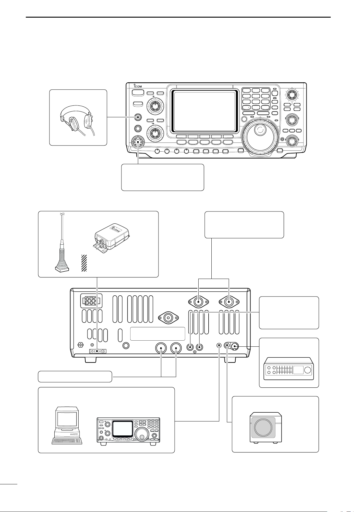
FILTER
HEADPHONES
MIC
The AFSK modulation signal
can be input from [MIC]. (p. 78)
AH-2b
AH-4 (p. 77)
ANTENNA 1, 2 (p. 17)
Connects a linear amplifier,
antenna selector, etc.
[SEND], [ALC] (p. 17)
Used for connecting a
non-Icom linear amplifier.
When using the AH-4, it must
be connected to the [ANT1]
connector.
[REMOTE] (p. 95)
Used for computer control and transceive operation.
[D ATA] (p. 78)
EXTERNAL SPEAKER (p. 101)
SP-21
(optional)
ACC SOCKETS (pgs. 8, 78)
INSTALLATION AND CONNECTIONS
■ Advanced connections
• Front panel
• Rear panel
15
Page 29
INSTALLATION AND CONNECTIONS
30 A fuses
AC cable
Transceiver
AC outlet
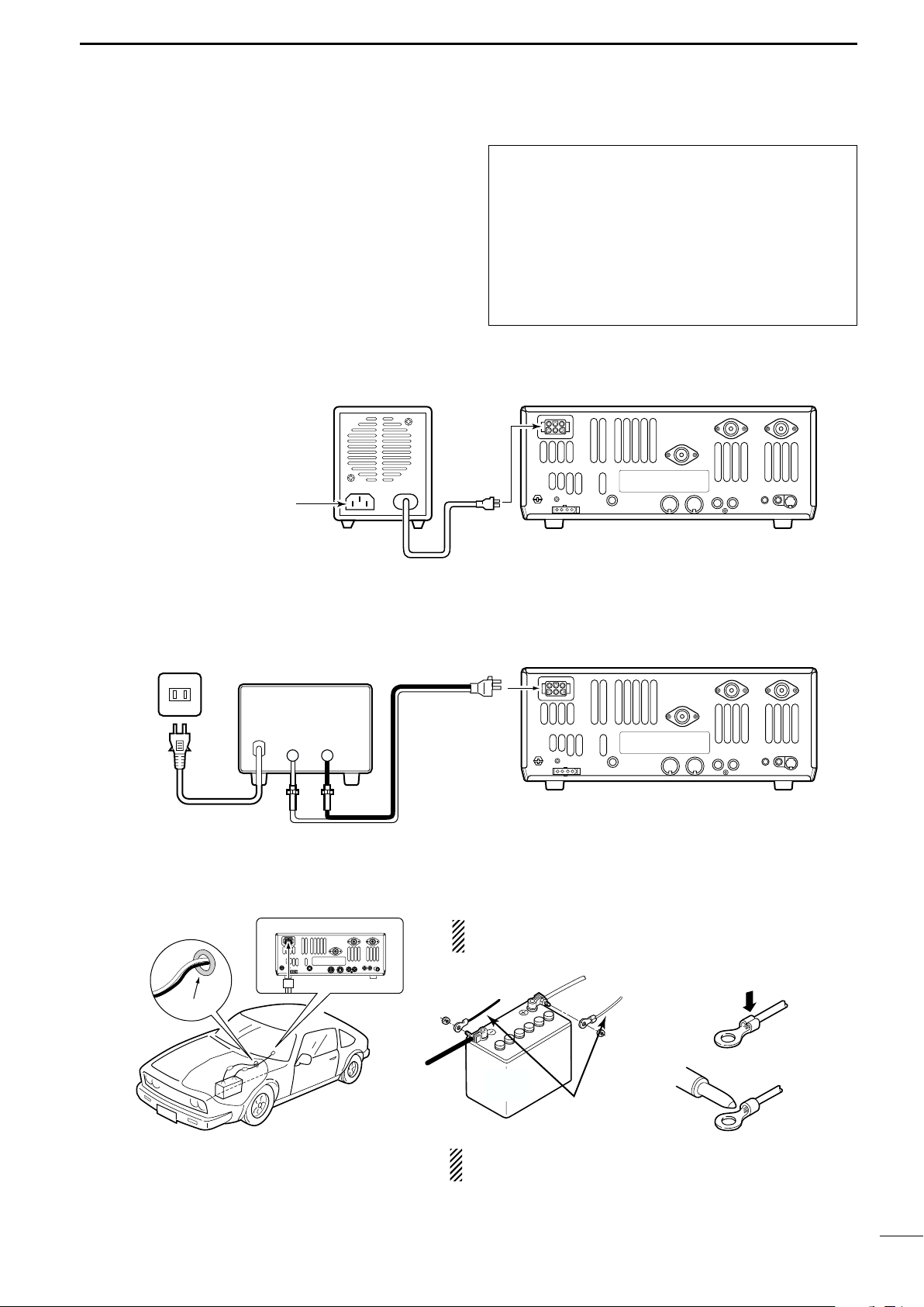
A DC power supply
13.8 V; at least 23 A
Black_Red
+
to DC power
socket
Supplied
DC power cable
12 V
battery
Supplied
DC power cable
+ red
_ black
Crimp
Solder
Grommet
PS-125
Connect to an AC outlet
using the supplied AC cable.
DC power cable
DC power
socket
Transceiver
2
■ Power supply connections
Use an optional DC power supply with a 25 A capacity
and above when operating the transceiver with AC
power. Refer to the diagrams below.
CONNECTING PS-125 DC POWER SUPPLY
CAUTION: Before connecting the DC power
cable, check the following important items. Make
sure:
• The [POWER] switch is OFF.
•Output voltage of the power source is 12–15 V
when you use a non-Icom power supply.
• DC power cable polarity is correct.
Red : positive + terminal
Black : negative _ terminal
CONNECTING A DC POWER SUPPLY
CONNECTING A VEHICLE BATTERY
NEVER connect to
a 24 V battery.
NOTE: Use terminals for
the cable connections.
NEVER connect to a battery without supplied DC
fuses, otherwise a fire hazard may occur.
16
Page 30

2
To an
antenna
ACC(1)
ANT
ANT1
ACC(2)
INPUT1
REMOTE
EXCITER
1
1&2
GND
GND
IC-PW1
AC outlet
(Non-European versions: 100—120/220—240 V
European version : 230 V)
Ground
Transceiver
REMOTE
Remote control cable (supplied with the IC-PW1)
ACC cable (supplied with the IC-PW1)
Be sure to connect the cable
to the 7-pin ACC(2) jack.
Coaxial cable
(supplied with the IC-PW1)
Coaxial cable (from AH-4)
ANT1
Transceiver
Ground
AH-4
Control cable
Long wire or optional AH-2b
50 Ω coaxial cable
Non-Icom linear amplifier
SEND
ALC
To an
antenna
RF OUTPUT RF INPUT
ALC
SEND
ANT1
Transceiver
INSTALLATION AND CONNECTIONS
■ Linear amplifier connections
CONNECTING THE IC-PW1
Use the [ANT1] connector when connecting a linear
amplifier.
Turn OFF the transceiver’s antenna tuner while tuning the IC-PW1’s tuner.
CONNECTING A NON-ICOM LINEAR AMPLIFIER
■ External antenna tuner connections
CONNECTING THE AH-4
The AH-4 must be connected to [ANT1].
17
R WARNING:
Set the transceiver output power and linear amplifier ALC output level referring to the linear amplifier
instruction manual. Be sure the linear amplifier keying circuit control voltage is compatible with the IC746PRO, before connecting to [SEND] jack.
The ALC input level must be in the range 0 V to –4
V, and the transceiver does not accept positive voltage. Non-matched ALC and RF power settings
could cause a fire or ruin the linear amplifier.
The specifications for the SEND relay are 16 V/DC
0.5 A. If this level is exceeded, a large external
relay must be used.
Page 31

BASIC OPERATION
POWER
TRANSMIT
PHONES
ELEC-KEY
MIC
NR
A
/NOTCH
TUNER
ANT
HF/VHF TRANSCEIVER
NR
NOTCH
AF
MIC GAIN
RF PWR
CW PITCH
F 1
F 2F 3
F 4
F 5
XFC
MP-W
GENE
50
0
21
7
24
8
28
9
14
5
10
4
18
6
3.5
2
1.8
1
7
3
144
ENT
MP-R
TX
RX
LOCK
TWIN PBT
M-CH
RIT
CLEAR
∂TX
RIT/∂TX
TS
SPLIT
PBTC
F-INP
A/B
V/M
MW
M-CL
KEY SPEED
P.AMP/ATT
NB
VOX/BK-IN
MONITOR
CALL
LOCK/
SPCH
RF/SQL
i746PRO
MENU
SSB
CW/RTTY
AM/FM
FILTER
[NR]: Max. CCW [NOTCH]: Max. CCW
[AF]: Max. CCW
[TRANSMIT]: OFF
[MIC GAIN]: Max. CCW
[RF PWR]: Max. CCW [CW PITCH]: 12 o’clock
[RF/SQL]: 12 o’clock
[KEY SPEED]: Max. CCW
[POWER] [F-INP] [M-CL]
■ When first applying power (CPU resetting)
Before first applying power, make sure all connections
required for your system are complete by referring to
Chapter 2. Then, reset the transceiver using the following procedure.
NOTE: When first applying power or when operat-
ing in cold environments, the display may flicker or
appear faint. This is normal and will disappear once
the transceiver has warmed up.
q Make sure the transceiver power is OFF.
w While pushing [M-CL] and [F-INP], push [POWER]
for 1 sec. to turn power ON.
• The internal CPU is reset.
•The transceiver displays its initial VFO frequency when
resetting is complete.
e Correct the set mode settings after resetting, if de-
sired.
Resetting CLEARS all programmed contents in
memory channels and returns programmed values
in set mode to default values.
3
■ Initial settings
After resetting the transceiver, set controls and
switches as shown in the figure below.
CW : Clockwise
CCW : Counterclockwise
18
Page 32

3
Band keys
BASIC OPERATION
■ Selecting an operating band
The transceiver has a triple band stacking register.
This means that the last 3 operating frequencies and
modes used on a particular band are automatically
memorized.
See the table below for a list of the bands available
and the default settings for each register.
BAND REGISTER 1 REGISTER 2 REGISTER 3
1.8 MHz 1.900000 MHz CW 1.910000 MHz CW 1.915000 MHz CW
3.5 MHz 3.550000 MHz LSB 3.560000 MHz LSB 3.580000 MHz LSB
7 MHz 7.050000 MHz LSB 7.060000 MHz LSB 7.020000 MHz CW
10 MHz 10.120000 MHz CW 10.130000 MHz CW 10.140000 MHz CW
14 MHz 14.100000 MHz USB 14.200000 MHz USB 14.050000 MHz CW
18 MHz 18.100000 MHz USB 18.130000 MHz USB 18.150000 MHz USB
21 MHz 21.200000 MHz USB 21.300000 MHz USB 21.050000 MHz CW
24 MHz 24.950000 MHz USB 24.980000 MHz USB 24.900000 MHz CW
28 MHz 28.500000 MHz USB 29.500000 MHz USB 28.100000 MHz CW
50 MHz 50.100000 MHz USB 50.200000 MHz USB 51.000000 MHz FM
144 MHz 145.000000 MHz FM 145.100000 MHz FM 145.200000 MHz FM
General 15.000000 MHz USB 15.100000 MHz USB 15.200000 MHz USB
D Using the band stacking registers
q Push [14 5], then select a frequency and an operat-
ing mode.
•Frequency and operating mode are memorized in the
first band stacking register.
w Push [14 5] again, then select another frequency
and operating mode.
•This frequency and operating mode are memorized in
the second band stacking register.
e Push [14 5] again, then select another frequency
and operating mode.
•This frequency and operating mode are memorized in
the third band stacking register.
•When a fourth frequency and operating mode are selected on a band, the first register set in step q, is overwritten.
[Example]: 14 MHz band
3.5
1
1. 8
4
10
21
GENE
14
24
7
50
2
5
8
0
7
18
28
14 4
3
6
9
ENT
19
Page 33

■ Selecting VFO/memory mode
[A/B]
Either one appears
Push for 1 sec.
A/B
[V/M]
VFO is an abbreviation of Variable Frequency Oscillator, and is commonly referred to as a main tuning function. The tuning dial is often called the “VFO knob.”
➥ Push [V/M] to switch between VFO and memory
modes.
•Pushing [V/M] for 1 sec. transfers the contents of the selected memory channel to VFO mode (p. 65).
■ VFO operation
The transceiver has 2 VFOs and are called VFO A and
VFO B. You can use the desired VFO to call up a frequency and operating mode for your operation.
BASIC OPERATION
3
DD
Selecting the VFO A/B
➥ Push [A/B] to switch between the VFO A and
VFO B.
•“VFO A” or “VFO B” appears.
DD
VFO equalization
➥ Push [A/B] for 1 sec. to equalize the undisplayed
VFO condition to the displayed VFO.
•3 beeps sound when the VFO equalization is completed.
CONVENIENT
Use two VFOs as a quick memory
When you find a new station, but you wish to continue
searching, the Two VFO system can be used for quick memory storage.
q Push [A/B] for 1 sec. to store the displayed frequency into
the undisplayed VFO.
w Continue searching for stations.
e Push [A/B] to retrieve the stored frequency.
r To continue searching for a station, push [A/B] again.
20
Page 34

3
Band keys
Tuning dial
[TS]Select mode
1kHz
SSB
1
⁄4 indicator
27
HIGH
DIAL Auto TS
BASIC OPERATION
■ Frequency setting
The transceiver has several tuning methods for convenient frequency tuning.
DD
Tuning with the tuning dial
q Push the desired band key on the keypad 1–3
times.
•3 different frequencies can be selected on each band
with the band key. (p. 19)
w Rotate the tuning dial to set the desired frequency.
If the dial lock function is activated, the lock indicator
lights, and the tuning dial does not function. In this
case, push [LOCK/SPCH] to deactivate the lock
function. (see p. 53 for details)
DD
Quick tuning step
The operating frequency can be changed in kHz steps
(0.1, 1, 5, 9, 10, 12.5, 20 or 25 kHz selectable) for
quick tuning.
q Push [SSB], [CW/RTTY] or [AM/FM] to select the
desired operation mode.
w Push [TS] momentarily to activate the quick tuning
function.
•“▼” appears.
e Push [TS] for 1 sec. to enter the tuning step set
mode.
r Rotate the tuning dial to select the desired tuning
step.
t Push [TS] to exit the tuning step set mode.
1
DD
⁄4 Tuning step function (SSB data, CW and RTTY only)
While operating in SSB data/CW/RTTY, the 1⁄4 function
is available for critical tuning. Dial rotation is reduced to
1
⁄4 of normal when the 1⁄4 function is in use.
➥ While M1 is selected with [MENU], push [F3 1/4]
to toggle the
1
⁄4 function ON and OFF.
D Auto tuning step function
When rotating the tuning dial rapidly, the tuning step
automatically changes several times as selected.
q Push [MENU] for 1 sec. to enter the set mode.
w Push [F1≤] or [F2 ≥] to select the DIAL Auto
TS item.
e Rotate the tuning dial to select the function ON
(HIGH or LOW) and OFF.
• HIGH : Approx. 5 times faster
• LOW : Approx. 2 times faster
• OFF : Auto tuning step is turned OFF.
r Push [MENU] to exit the set mode.
21
Page 35

DD
Lights when keypad input is activated.
Keypad [F-INP]
21.280 MHz 21.245 MHz
14.025 MHz
Push
[EXAMPLE]
50
0
21
7
14
5
10
4
10
4
18
6
3.5
2
1. 8
1
F-INP
GENE
50
0
50
0
3.5
2
GENE
14
5
144
ENT
706 kHz
Push
144
ENT
144
ENT
F-INP
GENE
Push
F-INP
Selecting the 1 Hz step
The minimum tuning step of 1 Hz can be used for fine
tuning.
q Push [TS] momentarily to turn the quick tuning step
OFF
•“▼” disappears.
w Push [TS] for 1 sec. to toggle the 1 Hz tuning step
ON and OFF.
DD
Band edge warning beep
When selecting a frequency that lies outside of a
band’s specified frequency range, a warning beep
sounds.
This function can be turned OFF in set mode, if desired. (p. 82)
BASIC OPERATION
[TS]
1 Hz indicator
3
DD
The transceiver has a keypad for direct frequency
entry as described below.
q Push [F-INP].
w Input the desired frequency.
e Push [144 ENT] to enter the input frequency.
Frequency setting with the keypad
• F-INP indicator lights
•Input “•” (decimal point) between the MHz units and kHz
units.
• To cancel the input, push [A/B] instead of [144 ENT].
22
Page 36

3
AF RF/SQL
No audio output
Max. audio output
Decreases Increases
[SSB] [CW/RTTY] [AM/FM]
SSB
CW/RTTY
AM/FM
D USB USB
CW-R CW
D AM AM
Push mode switch
for 1 sec.
Push mode switch
momentarily.
LSB D LSB
RTTY RTTY-R
FM D FM
BASIC OPERATION
■ Operating mode selection
SSB (USB/LSB), SSB data (USB data/LSB data), CW,
CW reverse (CW-R), RTTY, RTTY-R (RTTY reverse),
AM, AM data, FM and FM data modes are available in
the IC-746PRO. Select the desired operation mode as
follows.
To select a mode of operation, push the desired mode
switch momentarily. Push the switch again to toggle
between USB and LSB, CW/CW-R and RTTY/RTTYR, AM and FM, if necessary. Push the switch for 1 sec.
to toggle between CW and CW-R, RTTY and RTTY-R,
or to select data mode, if necessary.
See the diagram below right for the order of selection.
Microphone signals are muted when data mode is
selected.
• Selecting SSB mode
➥ Push [SSB] to select USB or LSB.
•USB is selected first when above 10 MHz; or LSB is selected first when below 10 MHz operation.
•After USB or LSB is selected, push [SSB] to toggle between USB and LSB.
•After USB or LSB is selected, push [SSB] for 1 sec. to
select USB data or LSB data mode, respectively.
• Selecting CW/RTTY mode
➥ Push [CW/RTTY] to select CW or RTTY.
•After CW/CW-R or RTTY/RTTY-R is selected, push
[CW/RTTY] to toggle between CW and RTTY.
•After CW or RTTY is selected, push [CW/RTTY] for
1 sec. to toggle between CW and CW reverse, or, RTTY
and RTTY reverse mode, respectively.
• Selecting AM/FM mode
➥ Push [AM/FM] to select AM or FM.
•After AM or FM is selected, push [AM/FM] to toggle between AM and FM mode.
•After AM or FM is selected, push [AM/FM] for 1 sec. to
select AM data or FM data mode, respectively.
■ Volume setting
➥ Rotate [AF] control to output a suitable audio level.
[AF] control
23
Page 37

Squelch is
open.
S-meter
squelch
S-meter squelch
threshold
Noise squelch
threshold
(FM mode)
Shallow Deep
Noise squelch (FM mode)
Minimum RF gain
Adjustable
range
Maximum
RF gain
Recommended level
RF gain
adjustable
range
Maximum
RF gain
S-meter
squelch
Noise squelch (FM mode)
Squelch is
open.
■ Squelch and receive (RF) sensitivity
[RF/SQL] control
Adjusts the RF gain and squelch threshold level. The
squelch removes noise output from the speaker
(closed position) when no signal is received.
•The squelch is particularly effective for FM. It is also available for other modes.
•The control can be set as the RF gain control only (squelch
is fixed open) or squelch control (RF gain is fixed at maximum) in set mode (p. 82). See below right.
•The 11 to 12 o’clock position is recommended for any set-
ting of the [RF/SQL] control.
BASIC OPERATION
3
SET MODE OPERATION
Can be used in all modes.
RF+SQL
(default)
Functions as noise squelch or S-meter
squelch in AM and FM; S-meter
squelch only in other modes.
SQL
➥ Operates as a squelch control.
• RF gain is fixed at max. sensitivity.
➥ Operates as an RF gain control in
SSB, CW and RTTY.
AUTO •Squelch is fixed open.
➥ Operates as a squelch control in AM
and FM.
• RF gain is fixed at max. sensitivity.
Adjusting RF gain (Receive sensitivity)
Normally, [RF/SQL] is set to the 11 o’clock position.
Rotate [RF/SQL] to the 11 o’clock position for maximum sensitivity.
•Rotating counterclockwise from the maximum position reduces sensitivity.
• The S-meter indicates receive sensitivity.
• When setting as RF gain/squelch control
• When functioning as RF gain control (Squelch is
fixed open; SSB, CW, RTTY only)
Adjusting squelch (Removing non-signal noise)
Rotate [RF/SQL] clockwise when receiving no signal,
until the noise just disappears.
• [RX] indicator light goes out.
•Rotating [RF/SQL] past the threshold point invokes the S-
meter squelch— this allows you to set a minimum signal
level needed to open the squelch.
•When functioning as squelch control (RF gain is
fixed at maximum)
24
Page 38

3
[TRANSMIT]
[RF PWR][MIC GAIN]
[TX] indicator
ALC zone
BASIC OPERATION
■ Basic transmit operation
Before transmitting, monitor your selected operating frequency to make sure transmitting won’t
cause interference to other stations on the same
frequency. It’s good Amateur practice to listen
first, and then, even if nothing is heard, ask “is
the frequency in use” once or twice, before you
begin operating on that frequency.
DD
Transmitting
Before transmitting, monitor your selected operating
frequency to make sure transmitting won’t cause interference to other stations on the same frequency.
q Push [TRANSMIT] or [PTT] (microphone) to trans-
mit.
• The [TX] indicator lights red.
w Push [TRANSMIT] again or release [PTT] (micro-
phone) to return to receive.
DD
Microphone gain adjustment
Before transmitting, monitor your selected operating
frequency to make sure transmitting won’t cause interference to other stations on the same frequency.
q Push [PTT] (microphone) to transmit.
• Talk into the microphone at your normal voice level.
w While talking into the microphone, rotate [MIC
GAIN] so that the ALC meter reading doesn’t go
outside the ALC zone (see right).
e Release [PTT] (microphone) to return to receive.
25
Page 39

RECEIVE AND TRANSMIT
Band keys[TX] indicator[TRANSMIT]
[MIC GAIN] [SSB] Tuning dial
“LSB” or “USB” appears
■ Operating SSB
q Push a band key to select the desired band.
w Push [SSB] to select LSB or USB.
•Below 10 MHz LSB is automatically selected; above
10 MHz USB is automatically selected.
e Rotate [AF] to set audio to a comfortable listening
level.
r Rotate the tuning dial to tune a desired signal.
• S-meter indicates received signal strength.
t Push [TRANSMIT] or [PTT] (microphone) to trans-
mit.
• The TX indicator lights red.
y Speak into the microphone at your normal voice
level.
• Adjust [MIC GAIN] at this step, if necessary.
u Push [TRANSMIT] or release [PTT] (microphone) to
return to receive.
4
DD
Convenient functions for receive
• Preamp and attenuator (p. 48)
➥ Push [P.AMP/ATT] several times to set the pre-
amp OFF, preamp 1 ON or preamp 2 ON.
•“P.AMP1,” “P.AMP2” or “P.AMP” appears when the
preamp 1, preamp 2 or preamp is set to ON, respectively. (depending on operating frequency band)
➥ Push [P.AMP/ATT] for 1 sec. to set the attenuator
ON.
•Push [P.AMP/ATT] momentarily to turn the attenuator
OFF.
•“ATT” appears when the attenuator is set to ON.
• Noise blanker (p. 51)
➥ Push [NB] to turn the noise blanker ON and OFF.
•“NB” appears when the noise blanker is set to ON.
• Push [NB] for 1 sec. to enter noise blanker set mode.
• Noise reduction (p. 53)
➥
Push [NR] to turn the noise reduction ON and OFF.
•Rotate [NR] control to adjust the noise reduction level.
•“NR” appears when the noise reduction is set to ON.
DD
Convenient functions for transmit
• Speech compressor (p. 58)
➥ While M1 is selected with [MENU], push
[F3 CMP] to turn the speech compressor ON and
OFF.
•“COMP” appears when the speech compressor is set
to ON.
• VOX (voice operated transmit) (p. 55)
➥ Push [VOX/BK-IN] to turn the VOX function ON
and OFF.
•“VOX” appears when the VOX function is set to ON.
• Auto notch filter (p. 53)
➥ Push [A/NOTCH] to turn the auto or manual
notch function ON and OFF.
•Rotate [NOTCH] control to set the attenuating frequency for manual notch operation.
• Twin PBT (passband tuning) (p. 52)
➥ Rotate [TWIN PBT] controls (inner/outer).
• Push [PBTC] to clear the settings.
• AGC (auto gain control) (p. 49)
➥ While M1 is selected with [MENU], push
[F1 AGC] several times to select AGC F,
AGC M, AGC S or AGC OFF.
• VSC (voice squelch control) (p. 54)
➥ While M2 is selected with [MENU], push
[F5 VSC] to turn the VSC function ON and OFF.
•The VSC indicator appears when the voice squelch
function is set to ON.
• Transmit quality monitor (p. 57)
➥ Push [MONITOR] to turn the monitor function ON
and OFF.
•“MONI” appears when the monitor function is set to
ON.
• Audio tone control (p. 89)
➥ While M2 is selected with [MENU], push [F4
TCN], select an item with [F1 ≤] and [F2 ≥] then
rotate the tuning dial to adjust the audio tone.
26
Page 40

4
Band keys[TX] indicator[TRANSMIT]
[CW PITCH]
[KEY SPEED]
[CW/RTTY]
Tuning dial
“CW” or “CW-R” appears
RECEIVE AND TRANSMIT
■ Operating CW
q Push a band key to select the desired band.
w Push [CW/RTTY] to select CW.
•After CW mode is selected, push [CW/RTTY] for 1 sec.
to toggle between CW and CW-R modes.
e Rotate [AF] to set audio to a comfortable listening
level.
r Rotate the tuning dial to simultaneously tune a de-
sired signal and its side tone.
• S-meter indicates received signal strength.
t Push [TRANSMIT] to transmit.
• The TX indicator lights red.
y Use the electric keyer or paddle to key your CW sig-
nals.
• The Po meter indicates transmitted CW signal strength.
u Adjust CW speed with [KEY SPEED].
i Push [TRANSMIT] to return to receive.
DD
Convenient functions for receive
• Preamp and attenuator (p. 48)
➥ Push [P.AMP/ATT] several times to set the pre-
amp OFF, preamp 1 ON or preamp 2 ON.
•“P.AMP1,” “P.AMP2” or “P.AMP” appears when the
preamp 1, preamp 2 or preamp is set to ON, respectively. (depending on operating frequency band)
➥
Push [P.AMP/ATT] for 1 sec. to set the attenuator
ON.
•Push [P.AMP/ATT] momentarily to turn the attenuator
OFF.
•“ATT” appears when the attenuator is set to ON.
• Noise blanker (p. 51)
➥ Push [NB] to turn the noise blanker ON and OFF.
•“NB” appears when the noise blanker is set to ON.
• Push [NB] for 1 sec. to enter noise blanker set mode.
• Noise reduction (p. 53)
➥ Push [NR] to turn the noise reduction ON and
OFF.
•Rotate [NR] control to adjust the noise reduction level.
•“NR” appears when the noise reduction is set to ON.
DD
Convenient functions for transmit
• Break-in function (p. 56)
➥ Push [VOX/BK-IN] several times to set the break-
in OFF, semi break-in or full break-in.
•“BK-IN” or “F BK-IN” appears when the semi break-in
or full break-in is set to ON, respectively.
• Auto notch filter (p. 53)
➥ Push [A/NOTCH] to turn the auto or manual
notch function ON and OFF.
•Rotate [NOTCH] control to set the attenuating frequency for manual notch operation.
• Twin PBT (passband tuning) (p. 52)
➥ Rotate [TWIN PBT] controls (inner/outer).
• Push [PBTC] to clear the settings.
• AGC (auto gain control) (p. 49)
➥ While M1 is selected with [MENU], push
[F1 AGC] several times to select AGC F,
AGC M, AGC S or AGC OFF.
•1⁄4 function (p. 21)
➥ While M1 is selected with [MENU], push
[F3 1/4] to turn the 1⁄4 function ON and OFF.
27
Page 41

DD
Push for 1 sec.
BFO
CW-R mode (USB side)
BFO
Desired signal
CW mode (LSB side)
Interference
Desired signalInterference
CW/RTTY
[CW PITCH]
[KEY SPEED]
About CW reverse mode
CW reverse mode receives CW signals with a reverse
side CW carrier point like that of LSB and USB modes.
Use when interfering signals are near a desired signal
and you want to change the interference tone.
q Push [CW/RTTY] several times to select CW mode.
w Push [CW/RTTY] for 1 sec. to select CW or CW-R
mode.
• Check the interfering tone.
DD
About CW pitch control
The received CW audio pitch and monitored CW audio
can be adjusted to suit your preference (300 to 900 Hz
in 25 Hz steps) without changing the operating frequency.
RECEIVE AND TRANSMIT
4
DD
About keying speed
The transceiver’s internal electronic keyer speed can
be adjusted from 6 to 60 wpm.
➥ Rotate [KEY SPEED] clockwise to increase keying
speed; counterclockwise to decrease keying speed.
DD
CW side tone function
When the transceiver is in the receive condition (and
the break-in function is OFF— p. 56) you can listen to
the tone of your CW signal without actually transmitting. This allows you to match your transmit signal exactly to another station’s. This also convenient for CW
practice. CW side tone level can be adjusted in keyer
set mode (p. 33).
28
Page 42

4
F 1F 2F 3F 4F 5
F 1F 2F 3F 4F 5
F 1F 2F 3F 4F 5
F 1F 2F 3F 4F 5
F 1F 2F 3F 4F 5
F 1F 2F 3F 4F 5
AGC DUP 1/4 KEY SCP
M1
M2
M3
M4
-1
5O%1
Side
Tone Level
Normal1
Number
Style
CQ
TEST CQ TEST
M1
ç
å
DEL SPC
Push [F4]
Push [MENU]
Push
[F4]
Push
[F2]
Push
[F3]
Push
[F5]
• Keyer send menu (p. 30)
SND EDT 001 SET
• Memory keyer menu
• Keyer set mode (p. 33)
• Contest number set mode (p. 32)
• Edit menu (p. 31)
[MENU] [CW/RTTY]
RECEIVE AND TRANSMIT
■ Electronic keyer functions
The transceiver has a number of convenient functions
for the electronic keyer that can be accessed from the
memory keyer menu.
q Push [CW/RTTY] to select CW mode.
w Push [MENU] to select M1.
e Push [F4 KEY] to select the memory keyer menu.
•The selectable menu can be changed with the keyer
send menu in the set mode. (p. 87)
r Push one of the multi-function keys ([F1] to [F5]) to
select an item in the memory keyer menu. See the
diagram below.
• Push [MENU] to return to the previous indication.
DD
IN CW MODE
29
Page 43

F 1
F 2F 3
F 4
F 5
F 2
F 1
F 4
F 3
Repeat indicators Count up trigger
indicator
Counter
M1
M2
M3
M4
-1
M1
M2
M3
M4
-1
M2 send indication
M1
M2
M3
M4
-1
CQ
TEST CQ
001
CQ
TEST CQ
001
QRZ?
M1
M2
M3
M4
-1
UR
5NN001 B 001
001
M1
M2
M3
M4
-1
UR
5NN001 B 001
CFM
TU
001
M1 send indication
M2 send indicationRepeat send indication
M1
M2
M3
M4
-1
M4 send indication
M1
M2
M3
M4
-1
M3 send indication
DD
Memory keyer send menu
Pre-set characters can be sent using the keyer send
menu. Contents of the memory keyer are set using the
edit menu.
• Transmitting
q While M1 is selected in CW mode, push [F4 KEY]
to select the memory keyer menu.
w Push [F2 SND] to select the keyer send menu.
e Push [TRANSMIT] to set the transceiver to trans-
mit, or set the break-in function ON (p. 56).
r Push one of the function keys ([F1] to [F4]) to send
the contents of the memory keyer.
•Pushing a function key for 1 sec. repeatedly sends the
contents; push any function key to cancel the transmission.
•The contest number counter, above [F5], is incremented
each time the contents are sent.
•Push [F5] to reduce the contact number count by 1 when
resending contents to unanswered calls.
For your information
When an external keypad is connected to the
pin 3 and pin 7 of the [MIC] connector, the programmed contents, M1—M4, can be transmitted
without selecting the keyer send menu.
See p. 87 for details.
RECEIVE AND TRANSMIT
4
t Push [MENU] 2 times to return to M1.
30
Page 44

4
DD
RECEIVE AND TRANSMIT
Editing a memory keyer
The contents of the memory keyer memories can be
set using the memory keyer edit menu. The memory
keyer can memorize and re-transmit 4 CW key codes
for often-used CW sentences, contact numbers, etc.
Total capacity of the memory keyer is 50 characters
per memory channel.
• Programming contents
q Push [MENU] to select M1, then push [F4 KEY] to
select the memory keyer menu.
w Push [F3 EDIT] to select edit menu.
•Memory keyer contents of the Channel 1 (M1) is indi-
cated.
• Push [F5] to manually increment the contest number.
e Push [F1] to select the desired memory keyer chan-
nel to be edited.
r Input the desired character by rotating the tuning
dial or by pushing the keypad for number input.
• Selectable characters (with the tuning dial);
A B C D E F G H I J K L M N O P Q R S T
U V W X Y Z / ? . , * ^
• Edit menu
ç
M1
F 1
CQ TEST CQ TEST
å
F 2F 3
DEL SPC
F 4
F 5
NOTE:
“^” is used to transmit a following word with no
space such as
AR
. Put “^” before a text string
such as ^AR, and the string “AR” is sent with no
space.
“*” is used to insert the CW contact number. The
contact number automatically increments by 1.
This function is only available for one memory
keyer channel at a time. Memory keyer channel
M2 used “*” by default.
t Push [F2 ç] or [F3 å] to move the cursor back-
wards or forwards, respectively.
y Repeat steps r and t to input the desired charac-
ters.
u Push [MENU] 2 times to return to M1.
Pre-programmed contents
CH Contents
M1 CQ TEST CQ TEST DE JA1 JA1 TEST
M2 UR 5NN* BK
M3 CFM TU
M4 QRZ?
Move cursor left/right
Select M1 to M4
Clear character
Input space
¥ M2 default indication
UR
5NN* BK
M2
ç
å
When inputting an asterisk,
the counter is incremented by 1.
DEL SPC
¥ M3 default indication
CFM TU
M3
ç
å
DEL SPC
¥ M4 default indication
QRZ?
M4
ç
å
DEL SPC
Example display— when inputting QSL TU
DE JA3YUA TEST into M3.
31
M3
M3
QSL TU DE JA3Y
ç
ç
å
DE
JA3YUA TEST
å
DEL SPC
DEL SPC
Page 45

DD
F 1
F 2F 3
F 4
F 5
1
Set item up/down
5O%
Side
Tone Level
M22
Count
Up Trig
Normal1
Number
Style
CLR
0013
Present
Number
Contest number set mode
This menu is used to set the contest (serial) number
and count up trigger, etc.
• Setting contents
q Push [MENU] to select M1, then push [F4 KEY] to
select the memory keyer menu.
w Push [F4 001] to enter the contest number set
mode.
e Push [F1≤] or [F2 ≥] to select the desired set item.
r Set the desired condition using the tuning dial.
•Push [F3] for 1 sec. to select a default condition or value.
t Push [MENU] 2 times to return to M1.
RECEIVE AND TRANSMIT
4
1. Number Style
This item sets the numbering system used for contact
(serial) numbers— normal or morse cut numbers.
•Normal : Does not use morse cut number
(default)
•190 ANO : Sets 1 as A, 9 as N and 0 as O.
•190 ANT : Sets 1 as A, 9 as N and 0 as T.
• 90 NO : Sets 9 as N and 0 as O.
• 90 NT : Sets 9 as N and 0 as T.
2. Count Up Trig
This selects which of the four memory slots will have
the contest serial number exchange. The count up
trigger allows the serial number to e automatically incremented after each complete serial number exchange is sent.
• M1, M2, M3 and M4 can be set. (default: M2)
3. Present Number
This item shows the current number for the count up
trigger channel set above.
•Rotate the tuning dial to change the number, or push
[F3 CLR] for 1 sec. to reset the current number to 001.
32
Page 46

4
F 1
F 2F 3
F 4
F 5
1
Set item up/down
5O%
Side
Tone Level
5O%1
Side
Tone Level
ON2
Side
Tone L-lmt
2s3
Repeat
Time
1:1:3.O4
Dot/Dash
Ratio
j
)
DD
RECEIVE AND TRANSMIT
Keyer set mode
This set mode is used to set the CW side tone, memory keyer repeat time, dash weight, paddle specifica-
tions, keyer type, etc.
• Setting contents
q Push [MENU] to select M1, then push [F4 KEY] to
select the memory keyer menu.
w Push [F5 SET] to select keyer set mode.
e Push [F1≤] or [F2 ≥] to select the desired set item.
r Set the desired condition using the tuning dial.
•Push [F3] for 1 sec. to select a default condition or value.
t Push [MENU] 2 times to return to M1.
1. Side Tone Level
This item sets the CW side tone output level.
• 0 to 100% in 1% steps can be selected.
2. Side Tone L-lmt
This item sets the CW side tone level limit. When the
[AF] control is rotated above a specified level, the CW
side tone does not increase.
ON CW side tone level is limited. (default)
OFF CW side tone level is not limited.
3. Repeat Time
When sending CW using the repeat timer, this item
sets the time between transmission.
• 1 to 60 sec. in 1 sec. steps can be selected.
4. Dot/Dash Ratio
This item sets the dot/dash ratio.
• 1:1:2.8 to 1:1:4.5 (in 0.12 steps) can be selected.
Keying weight example: Morse code “K”
DOT (fixed*)
Weight setting:
1:1:3 (default)
Weight setting:
Adjusted
33
ustable range SPACE (fixed*
Ad
DASH
DASH
*SPACE and DOT length can be
adjusted with [KEY SPEED] only.
Page 47

5. Rise Time
4ms5
Rise
Time
Key action
Tx output power
• About rise time
Tx
Rx
Set Tx power level
Time
NORMAL6
Paddle
Polarity
ELEC-KEY7
Keyer
Type
OFF8
MIC
U/D Keyer
This item sets the envelop time period which the output power becomes the set transmit power.
• 2, 4, 6 or 8 msec. can be selected.
6. Paddle Polarity
This item sets the paddle polarity.
• Normal and reverse polarity can be selected.
RECEIVE AND TRANSMIT
4
7. Keyer Type
This item selects the keyer type for [ELEC-KEY] connector on the front panel.
• ELEC-KEY, BUG KEY and Straight key can be selected.
8. MIC U/D Keyer
This item allows you to set the microphone [UP]/[DN]
keys to be used as a paddle.
ON [UP]/[DN] switches can be used for CW.
OFF [UP]/[DN] switches cannot be used for
CW.
NOTE: When “ON” is selected, the frequency and
memory channel cannot be changed using
the [UP]/[DN] switches.
34
Page 48

4
Band keys[TX] indicator[TRANSMIT]
[CW/RTTY] Tuning dial
“RTTY” or “RTTY-R” appears
RECEIVE AND TRANSMIT
■ Operating RTTY (FSK)
Before operating RTTY, be sure to consult the manual
that comes with your TNC.
q Push a band key to select the desired band.
w Push [CW/RTTY] several times to select RTTY.
• After RTTY mode is selected, push [CW/RTTY] for
1 sec. to toggle RTTY and RTTY-R modes.
e Rotate [AF] to set audio to a comfortable listening
level.
r Rotate the tuning dial to tune a desired signal.
• S-meter indicates received signal strength.
•If the received signal cannot be demodulated, try select-
ing RTTY-R mode.
t Push [TRANSMIT] to set the transceiver to the
transmit condition or transmit a SEND signal from
your TNC.
• The TX indicator lights red.
•
The Po meter indicates transmitted RTTY signal strength.
y Operate the connected PC or TNC (TU) to transmit
RTTY (FSK) signals.
• Adjust [MIC GAIN] at this step, if necessary.
u Push [TRANSMIT] to return to receive.
DD
Convenient functions for receive
• Preamp and attenuator (p. 48)
➥ Push [P.AMP/ATT] several times to set the pre-
amp OFF, preamp 1 ON or preamp 2 ON.
•“P.AMP1,” “P.AMP2” or “P.AMP” appears when the
preamp 1, preamp 2 or preamp is set to ON, respectively. (depending on operating frequency band)
➥ Push [P.AMP/ATT] for 1 sec. to set the attenuator
ON.
•Push [P.AMP/ATT] momentarily to turn the attenuator
OFF.
•“ATT” appears when the attenuator is set to ON.
• Noise blanker (p. 51)
➥ Push [NB] to turn the noise blanker ON and OFF.
•“NB” appears when the noise blanker is set to ON.
• Push [NB] for 1 sec. to enter noise blanker set mode.
DD
Convenient functions for transmit
• Transmit quality monitor (p. 57)
➥ Push [MONITOR] to turn the monitor function ON
and OFF.
•“MONI” appears when the monitor function is set to
ON.
• Noise reduction (p. 53)
➥ Push [NR] to turn the noise reduction ON and
OFF.
•Rotate [NR] control to adjust the noise reduction level.
•“NR” appears when the noise reduction is set to ON.
• Twin PBT (passband tuning) (p. 52)
➥ Rotate [TWIN PBT] controls (inner/outer).
• Push [PBT C] to clear the settings.
• AGC (auto gain control) (p. 49)
➥ While M1 is selected with [MENU], push
[F1 AGC] several times to select AGC F,
AGC M, AGC S or AGC OFF.
•1⁄4 function (p. 21)
➥ While M1 is selected with [MENU], push
[F3 1/4] to turn the 1⁄4 function ON and OFF.
35
Page 49

■ RTTY functions
F 1
F 2 F 3 F 4 F 5
F 1
F 2 F 3 F 4 F 5
F 1
F 2 F 3 F 4 F 5
F 1
F 2 F 3 F 4 F 5
F 1
F 2 F 3 F 4 F 5
F 1
F 2 F 3 F 4 F 5
AGC DUP 1/4 RTY SCP
DEC
FIL SET
21251
RTTY
Mark
35O1
Band
Width
ADJ
RTTY-FIL ON
DEC
FIL SET
• RTTY menu
• RTTY decoder screen (p. 38)
• RTTY filter set mode (p. 37)
• RTTY set mode (p. 39)
Push [F4]
Push
[F4] for
1 sec.
Switches RTTY filter ON and OFF.
Push
[F4]
Push
[F5]
Push [F2]
[MENU] [CW/RTTY]
Normal Reverse
170
Hz
170
Hz
2125
Hz
2125
Hz
BFOBFO
Space
Space
Mark
Mark
The transceiver has a number of convenient functions
for the RTTY operation that can be accessed from the
RTTY menu.
q Push [CW/RTTY] to select RTTY mode.
w Push [MENU] to select M1.
e Push [F4 RTY] to select the RTTY menu.
r Push one of the multi-function keys ([F2], [F4] or
[F5]) to select an item in the RTTY menu. See the
diagram below.
• Push [MENU] to return to the previous indication.
DD
IN RTTY MODE
RECEIVE AND TRANSMIT
4
DD
About RTTY reverse mode
Received characters are occasionally garbled when
the receive signal is reversed between MARK and
Space. This reversal can be caused by incorrect TNC
connections, setting, commands, etc. To receive reversed RTTY signals correctly, select RTTY-R mode.
➥ While RTTY mode is selected, push [CW/RTTY]
for 1 sec. to select the RTTY reverse mode.
•“RTTY-R” appears when the RTTY reverse mode is se-
lected.
•Push [CW/RTTY] for 1 sec. again to select the normal
RTTY mode.
36
Page 50

4
F1
F2 F3 F4 F5
F1
F2 F3 F4 F5
AGC DUP 1/4 RTY SCP
DEC
FIL SET
RTTY-FIL ON
Push [F4]
Disappears when the RTTY
filter is turned OFF.
RTTY filter indicator
Rotate the tuning dial to the
point where both sides of the
dots appear equally.
35O1
Band
Width
ON2
Twin
Peak FIL
DD
RECEIVE AND TRANSMIT
RTTY filter/Twin peak filter
The transceiver has 5 RTTY filters in addition to normal IF filters. The passband width can be selected
from 1 kHz, 500 Hz, 350 Hz, 300 Hz and 250 Hz.
When the RTTY filter is turned ON, the RTTY tuning
meter can be used.
Moreover, the twin peak filter changes the receive frequency response by boosting 2 particular frequencies
(2125 and 2295 Hz) for better copying of desired
RTTY signals.
• RTTY filter and twin peak filter setting
q Push [CW/RTTY] to select RTTY mode.
•After RTTY mode is selected, push [CW/RTTY] for 1 sec.
to select RTTY-R mode.
w Push [MENU] several times to select M1.
e Push [F4 RTY] to select RTTY menu.
r Push [F4 FIL] to turn the RTTY filter ON and OFF.
•When the RTTY filter is turned ON, the normal IF filter
number indication (1, 2 or 3) disappears.
t Push [F4 FIL] for 1 sec. to enter RTTY filter set
mode (see below).
y Push [F1≤] to select bandwidth item.
u Rotate the tuning dial to select the RTTY filter width
from 1 kHz, 500 Hz, 350 Hz, 300 Hz and 250 Hz.
• Push [F3] for 1 sec. to select a default value.
i Push [F2 ≥] to select twin peak filter item.
•The received audio volume may become greater when
the twin peak filter is turned ON.
o Rotate the tuning dial to turn the twin peak filter
function ON and OFF.
!0 Push [MENU] 2 times to return to M1.
• RTTY filter set mode
1. Band Width
This item sets the RTTY filter width.
• 250, 300, 350, 500 Hz and 1 kHz can be selected.
2. Twin Peak FIL
This item turns the twin peak filter ON and OFF.
37
Page 51

F 1
F 2 F 3 F 4 F 5
F 1
F 2 F 3 F 4 F 5
F 1
F 2 F 3 F 4 F 5
AGC DUP 1/4 RTY SCP
DEC
FIL SET
ADJ
RTTY-FIL ON
Push [F4]
Push [F2]
Appears while the RTTY decoder screen is freezed
with [F2] operation.
Push [F3] to erase the displayed characters.
DD
F 1
F 2 F 3 F 4 F 5
F 1
F 2 F 3 F 4 F 5
ADJ
å
9
Push [F1]
Threshold level indication
RTTY decoder
The transceiver has an RTTY decoder for Baudot
(mark freq.: 2125 Hz, shift freq.: 170 Hz, 45 bps).
An external terminal unit (TU) or terminal node connector (TNC) is not necessary for receiving a Baudot
signal.
q Push [CW/RTTY] to select RTTY mode.
•After RTTY mode is selected, push [CW/RTTY] for 1 sec.
to select RTTY-R mode.
w Push [MENU] several times to select M1.
e Push [F4 RTY] to select RTTY menu.
r Push [F4 FIL] to turn the RTTY filter ON.
•The RTTY decoder does not function when the RTTY filter is turned OFF.
t Push [F2 DEC] to turn the RTTY decoder ON.
• RTTY decoder screen appears.
y Push [F2] to freeze the current screen.
•“H” appears while the function is in use.
u Push [F3] for 1 sec. to clear the displayed charac-
ters.
i Push [MENU] to exit the RTTY decoder screen.
RECEIVE AND TRANSMIT
4
• Setting the decoder threshold level
Adjust the RTTY decoder threshold level if some characters are displayed when no signal is received.
q Call up the RTTY decoder screen as described
above.
w Push [F1 ADJ] to select the threshold level setting
condition.
e Rotate the tuning dial to adjust the RTTY decoder
threshold level.
• Push [F3] for 1 sec. to select the default condition.
r Push [MENU] to exit the RTTY decoder screen.
The number of line of text can be selected from 2 or
3 in the display. The UnShift On Space (USOS)
function and new line code can be set in the RTTY
set mode. (p. 39)
38
Page 52

4
F 1
F 2 F 3 F 4 F 5
21251
RTTY
Mark
Set item up/down
21251
RTTY
Mark
17O2
RTTY
Shift
NORMAL
3
RTTY
Keying
ON
4
Decode
USOS
CR,LF,CR+LF
5
Decode
New Line
3line
6
Decode
Screen
DD
This set mode is used to set the mark and shift frequencies, keying type, decode USOS function, etc.
• Setting contents
q Push [MENU] to select M1, then push [F4 RTY] to
w Push [F5 SET] to select RTTY set mode.
e Push [F1≤] or [F2 ≥] to select the desired set item.
r Set the desired condition using the tuning dial.
t Push [MENU] 2 times to return to M1.
RECEIVE AND TRANSMIT
RTTY set mode
select the RTTY menu.
•Push [F3] for 1 sec. to select a default condition or value.
1. RTTY Mark
Sets the mark frequency for RTTY operation.
• 1275, 1615 and 2125 Hz are selectable.
2. RTTY Shift
Sets the shift frequency for RTTY operation.
• 170, 200 and 425 Hz are selectable.
3. RTTY Keying
Selects the keying polarity from normal and reverse.
NORMAL Key open/close = Mark/Space
REVERSE Key open/close = Space/Mark
4. Decode USOS
Turn the USOS (UnShift On Space) function ON/OFF
ON Decode as letter code
OFF Decode as character code
5. Decode New Line
Selects the new line code of the internal RTTY decoder.
CR: Carriage Return; LF: Line Feed
CR,LF,CR+LF CR, LF and CR+LF
CR+LF CR+LF only
6. Decode Screen
Selects the number of the decoder indication from 2
or 3 lines.
39
Page 53

■ Operating AM
Band keys[TX] indicator[TRANSMIT]
[MIC GAIN] [AM/FM] Tuning dial
Appears
q Push a band key to select the desired band.
w Push [AM/FM] to select AM.
e Rotate [AF] to set audio to a comfortable listening
level.
r Rotate the tuning dial to tune a desired signal.
• S-meter indicates received signal strength.
•The default tuning step for AM mode is 1 kHz; this can
be changed using the tuning step program mode. (p. 21)
t Push [TRANSMIT] or [PTT] (microphone) to trans-
mit.
• The TX indicator lights red.
y Speak into the microphone at your normal voice
level.
• Adjust [MIC GAIN] at this step, if necessary.
u Push [TRANSMIT] or release [PTT] (microphone) to
return to receive.
RECEIVE AND TRANSMIT
4
DD
Convenient functions for receive
• Preamp and attenuator (p. 48)
➥ Push [P.AMP/ATT] several times to set the pre-
amp OFF, preamp 1 ON or preamp 2 ON.
•“P.AMP1,” “P.AMP2” or “P.AMP” appears when the
preamp 1, preamp 2 or preamp is set to ON, respectively. (depending on operating frequency band)
➥ Push [P.AMP/ATT] for 1 sec. to set the attenuator
ON.
•Push [P.AMP/ATT] momentarily to turn the attenuator
OFF.
•“ATT” appears when the attenuator is set to ON.
• Noise blanker (p. 51)
➥ Push [NB] to turn the noise blanker ON and OFF.
•“NB” appears when the noise blanker is set to ON.
• Push [NB] for 1 sec. to enter noise blanker set mode.
• Noise reduction (p. 53)
➥
Push [NR] to turn the noise reduction ON and OFF.
•Rotate [NR] control to adjust the noise reduction level.
•“NR” appears when the noise reduction is set to ON.
DD
Convenient functions for transmit
• Speech compressor (p. 58)
➥ While M1 is selected with [MENU], push [F3
CMP] to turn the speech compressor ON and
OFF.
•“COMP” appears when the speech compressor is set
to ON.
• VOX (voice operated transmit) (p. 55)
➥ Push [VOX/BK-IN] to turn the VOX function ON
and OFF.
•“VOX” appears when the VOX function is set to ON.
• Auto notch filter (p. 53)
➥ Push [A/NOTCH] to turn the auto or manual
notch filter ON and OFF.
•Rotate [NOTCH] control to set the attenuating frequency for manual notch operation.
• IF shift (p. 52)
➥ Rotate [TWIN PBT] controls (inner only).
• Push [PBTC] to clear the settings.
• AGC (auto gain control) (p. 49)
➥ While M1 is selected with [MENU], push [F1
AGC] several times to select AGC F, AGC M,
AGC S or AGC OFF.
• VSC (voice squelch control) (p. 54)
➥ While M2 is selected with [MENU], push
[F5 VSC] to turn the VSC function ON and OFF.
•The VSC indicator appears when the voice squelch
function is set to ON.
• Transmit quality monitor (p. 57)
➥ Push [MONITOR] to turn the monitor function ON
and OFF.
•“MONI” appears when the monitor function is set to
ON.
• Audio tone control (p. 89)
➥ While M2 is selected with [MENU], push [F4
TCN], select an item with [F1 ≤] and [F2 ≥] then
rotate the tuning dial to adjust the audio tone.
40
Page 54

4
Band keys[TX] indicator[TRANSMIT]
[MIC GAIN] [AM/FM] Tuning dial
Appears
RECEIVE AND TRANSMIT
■ Operating FM
q Push a band key to select the desired band.
w Push [AM/FM] to select FM.
e Rotate [AF] to set audio to a comfortable listening
level.
r Rotate the tuning dial to tune a desired signal.
• S-meter indicates received signal strength.
t Push [TRANSMIT] or [PTT] (microphone) to trans-
mit.
• The TX indicator lights red.
y Speak into the microphone at your normal voice
level.
• Adjust [MIC GAIN] at this step, if necessary.
u Push [TRANSMIT] or release [PTT] (microphone) to
return to receive.
DD
Convenient functions for receive
• Preamp and attenuator (p. 48)
➥ Push [P.AMP/ATT] several times to set the pre-
amp OFF, preamp 1 ON or preamp 2 ON.
•“P.AMP1,” “P.AMP2” or “P.AMP” appears when the
preamp 1, preamp 2 or preamp is set to ON, respectively. (depending on operating frequency band)
➥ Push [P.AMP/ATT] for 1 sec. to set the attenuator
ON.
•Push [P.AMP/ATT] momentarily to turn the attenuator
OFF.
•“ATT” appears when the attenuator is set to ON.
• Noise blanker (p. 51)
➥ Push [NB] to turn the noise blanker ON and OFF.
•“NB” appears when the noise blanker is set to ON.
• Push [NB] for 1 sec. to enter noise blanker set mode.
DD
Convenient functions for transmit
• Speech compressor (p. 58)
➥ While M1 is selected with [MENU], push [F3
CMP] to turn the speech compressor ON and
OFF.
•“COMP” appears when the speech compressor is set
to ON.
• VOX (voice operated transmit) (p. 55)
➥ Push [VOX/BK-IN] to turn the VOX function ON
and OFF.
•“VOX” appears when the VOX function is set to ON.
• Noise reduction (p. 53)
➥
Push [NR] to turn the noise reduction ON and OFF.
•Rotate [NR] control to adjust the noise reduction level.
•“NR” appears when the noise reduction is set to ON.
• Auto notch filter (p. 53)
➥ Push [A/NOTCH] to turn the auto or manual
notch filter ON and OFF.
•Rotate [NOTCH] control to set the attenuating frequency for manual notch operation.
• VSC (voice squelch control) (p. 54)
➥ While M2 is selected with [MENU], push
[F5 VSC] to turn the VSC function ON and OFF.
•The VSC indicator appears when the voice squelch
function is set to ON.
• Transmit quality monitor (p. 57)
➥ Push [MONITOR] to turn the monitor function ON
and OFF.
•“MONI” appears when the monitor function is set to
ON.
• Audio tone control (p. 89)
➥ While M2 is selected with [MENU], push [F4
TCN], select an item with [F1 ≤] and [F2 ≥] then
rotate the tuning dial to adjust the audio tone.
41
Page 55

DD
F 1
F 2 F 3 F 4 F 5
F 1
F 2 F 3 F 4 F 5
AGC DUP CMP TON SCP
TON
SCN
88.5Hz
TSQL Tone
Push [F4] for 1 sec.
Tone squelch operation
Tone squelch operation is a method of communications using selective calling. Only received signals having a matching tone will open the squelch. Before
communicating using tone squelch, all members of
your party must agree on the tone squelch frequency
to use.
q Push [AM/FM] to select FM mode.
w Push [MENU] several times to select M1.
e Push [F4 TON] several times to turn the tone
squelch function ON.
•“TSQL” appears
r Push [F4 TONE] for 1 sec. to enter tone frequency
set mode.
t Push [F1 TON] several times until TSQL Tone
appears, if necessary.
y Rotate the tuning dial to select the desired tone
squelch frequency.
• Push [F3] for 1 sec. to select the default frequency.
u Push [MENU] to return to M1.
i Communicate in the usual manner.
RECEIVE AND TRANSMIT
4
• Available tone squelch frequencies (Unit: Hz)
254.1
210.7
186.2
165.5
136.5
107.2
085.4
67.0
218.1
189.9
167.9
141.3
110.9
088.5
69.3
225.7
192.8
171.3
146.2
114.8
091.5
71.9
229.1
196.6
173.8
151.4
118.8
094.8
74.4
233.6
199.5
177.3
156.7
123.0
097.4
77.0
241.8
203.5
179.9
159.8
127.3
100.0
79.7
250.3
206.5
183.5
162.2
131.8
103.5
82.5
42
Page 56

4
F 1
F 2 F 3 F 4 F 5
F 1
F 2 F 3 F 4 F 5
AGC DUP CMP TON SCP
TON
SCN
O23-NN
DTCS Code
Push [F4] for 1 sec.
Push [F5] to select the polarity
Select a code with the tuning dial.
DD
RECEIVE AND TRANSMIT
DTCS operation
DTCS function is an another method of communications using selective calling. Only received signals having a matching 3-digit code will open the squelch.
q Push [AM/FM] to select FM mode.
w Push [MENU] several times to select M1.
e Push [F4 TON] several times to turn the DTCS
function ON.
•“DTCS” appears
r Push [F4 TON] for 1 sec. to enter tone frequency
set mode.
t Push [F1 TON] several times until DTCS Code
appears, if necessary.
y Rotate the tuning dial to select the desired DTCS
code number and push [F5] to select the desired
code polarity.
NN : Normal polarity is used for both transmit and
receive.
NR : Normal polarity is used for transmit, reversed
polarity is used for receive.
RN : Reversed polarity is used for transmit, normal
polarity is used for receive.
RR : Reversed polarity is used for both transmit
and receive.
•Push [F3] for 1 sec. to select the default code and polarity.
u Push [MENU] to return to M1.
i Communicate in the usual manner.
• Available tone codes
412
311
244
152
072
023
413
315
245
155
073
025
423
325
246
156
074
026
431
331
251
162
114
031
432
332
252
165
115
032
445
343
255
172
116
036
446
346
261
174
122
043
452
351
263
205
125
047
454
356
265
212
131
051
455
364
266
223
132
053
462
365
271
225
134
054
464
371
274
226
143
065
465
411
306
243
145
071
466
503
506
516
523
526
532
546
565
606
612
624
627
631
632
654
662
664
703
712
723
731
732
734
743
754
43
Page 57

■ Repeater operation
F 1
F 2 F 3 F 4 F 5
F 1
F 2 F 3 F 4 F 5
AGC DUP CMP TON SCP
AGC
DUP CMP TON SCP
145.O8OOO
Push [F2], [F4]
Appears
F 1
F 2 F 3 F 4 F 5
F 1
F 2 F 3 F 4 F 5
AGC DUP CMP TON SCP
AGC
DUP CMP TON SCP
145.O8OOO
Push [F2] for 1 sec.
Appears
A repeater amplifies received signals and retransmits
them at a different frequency. When using a repeater,
the transmit frequency is shifted from the receive frequency by an offset frequency. A repeater can be accessed using split frequency operation with the shift
frequency set to the repeater’s offset frequency.
q Push a band key to select the desired band.
w Push [A/B] to select VFO A.
e Push [AM/FM] to select FM.
• Pushing [AM/FM] toggles between AM and FM.
r Rotate the tuning dial to set the repeater transmit
frequency.
t While M1 is selected, push [F2 DUP] several times
to set the offset direction.
•“DUP–” or “DUP+” appears
•0.100 MHz for HF, 0.500 MHz for 50 MHz and
0.600 MHz for 144 MHz band is set by default in set
mode. (p. 83)
y Push [F4 TON] to turn the repeater tone ON.
•“T” appears.
•Set the tone frequency in tone frequency set mode in
advance, if desired. (p. 45) 88.5 Hz is set by default.
To transmit a 1750 Hz European repeater tone,
push [F4 TON] while transmitting.
u Communicate in the normal way.
RECEIVE AND TRANSMIT
4
DD
One-touch repeater function
This function allows you to set repeater operation with
push of one switch.
➥ To set the transceiver for repeater operation using
the one-touch repeater function, follow the steps q
to r as above, then push [F2 DUP] for 1 sec.
Set the offset shift direction and frequency in advance (p. 83) as well as the tone frequency (see
p. 45).
44
Page 58

4
AGC DUP CMP TON SCP
-6OO.Ok
[XFC]
[AM/FM] [SPLIT] [A/B] [M-CH]
[MW]
[V/M]
DD
RECEIVE AND TRANSMIT
Transmit frequency monitor check
You may be able to receive the other party’s transmit
signal directly without having to go through a repeater.
This function allows you to check this.
➥ While receiving, push and hold [XFC] to see if you
can receive the other party’s transmit signal directly.
•While holding [XFC], the offset direction and frequency
are displayed on the multi-function switch indicator.
DD
Repeater tone frequencies
The transceiver’s repeater tone frequency is set to
88.5 Hz by default. This can be changed if desired.
q While M1 is selected, push [F4 TON] to turn the
tone encoder ON.
•“T” appears.
w Push [F4 TON] for 1 sec. to select the tone fre-
quency set mode.
e Push [F1 TON] several times to select Rptr
Tone, if necessary.
r Rotate the tuning dial to select the desired fre-
quency. (see the table at right)
t Push [MENU] to return to M1.
Rptr Tone
TON SCN
88.5Hz
• Available tone frequencies (Unit: Hz)
254.1
210.7
186.2
165.5
136.5
107.2
085.4
67.0
218.1
189.9
167.9
141.3
110.9
088.5
69.3
225.7
192.8
171.3
146.2
114.8
091.5
71.9
229.1
196.6
173.8
151.4
118.8
094.8
74.4
233.6
199.5
177.3
156.7
123.0
097.4
77.0
241.8
203.5
179.9
159.8
127.3
100.0
79.7
250.3
206.5
183.5
162.2
131.8
103.5
82.5
DD
Storing a non standard repeater
q Turn the auto repeater function OFF in the set
mode. (p. 84)
w Push [AM/FM] to select FM mode.
e Push [V/M], then [A/B] to select VFO A.
r Rotate the tuning dial to set the repeater output fre-
quency.
• Set the tuning step if desired.
t Push [A/B] to select VFO B.
y Rotate the tuning dial to set the repeater input fre-
quency.
u Push [A/B] to select VFO A.
i Push [SPLIT] to turn the split function ON.
o Push [F4 TON] to turn the previously set tone en-
coder ON.
!0 Rotate [M-CH] to select the desired memory chan-
nel.
•“BLANK” appears when a blank channel is selected.
!1 Push [MW] for 1 sec. to store the contents in the se-
lected memory channel.
45
Page 59

DD
Auto repeater function
This function automatically activates the repeater settings (DUP– or DUP+ and/or tone encoder ON/OFF)
when the operating frequency falls within the general
repeater output frequency range and deactivates them
when outside of the range.
Set the auto repeater function ON-1 or ON-2 in set
mode in advance (p. 84). When set ON-1 or ON-2, repeater settings are automatically activated according
to the table below.
ON-1 automatically sets the duplex setting and ON-2
automatically sets the duplex setting and tone encoder
automatically.
• Frequency range and offset direction
FREQUENCY RANGE DUPLEX DIRECTION
145.200–145.495 MHz minus duplex
146.610–146.995 MHz minus duplex
147.000–147.395 MHz plus duplex
RECEIVE AND TRANSMIT
Auto Repeater
18
Auto Repeater
18
Auto Repeater
18
4
ON-1
ON-2
OFF
46
Page 60

5
“ ” or “ ”
0.5k
STEP
Sweep indicator
Band scope indicator
Frequency indicator mark
Sweep step indicator
“ ” or “ ”
F 1
F 2 F 3 F 4 F 5
F 1
F 2 F 3 F 4 F 5
Sweep step selectionSweep start/stop
O.5k
STEP
O.5k
STEP
Sweep indicator
FUNCTIONS FOR RECEIVE
■ Simple band scope
The band scope function allows you to visually check
signal conditions around a specified frequency. The IC746PRO’s band scope function can be used in any operating mode and frequency band.
INDICATOR
Sweep
Band scope in-
dicator
Frequency
indicator mark
Sweep step
The band scope measures receive signal conditions
over a specified range on either side of a selected fre-
quency in either VFO or memory modes.
q Rotate the tuning dial to tune a frequency.
w While M1 is selected, push [F5 SCP] to select the
band scope menu.
•Starts sweeping automatically with the previously selected sweeping step.
• During sweep, received signals cannot be heard.
e Push [F5 STEP] several times to select the desired
sweep step.
r Push [F1] to start sweeping, then stop automatically
after sweeping.
•Push [F1] for 1 sec. to start continuous sweeping. In this
case, it is necessary to push [F1] to stop sweeping.
•During sweep operation “” appears and received
signals cannot be heard.
•If there is a lot of signal noise, turn the preamp OFF and
the attenuator ON to reduce the signal input level and
improve the readability of the band scope.
t When rotating the tuning dial and you finding a sig-
nal you wish to communicate on, then just communicate in the normal way.
•If you want to return to the previous frequency (before
rotating the tuning dial), push [F3] for 1 sec.
y While receiving, if you want to update the band con-
47
•If the selected frequency is set outside of the sweeped
range, flashes.
ditions, repeat steps e and r as above.
DESCRIPTION
While the band scope is “sweeping,” “” appears; while stopped “” appears. Received
audio is not emitted from the speaker while the band scope is “sweeping.”
Indicates the relative strength of signals and their location in relation to the center (displayed)
frequency. Signal strength is relative to the S-meter level, S1 to S9, with each vertical dot in the
band scope indicator equal to one segment of the S-meter. Signal activity is measured ±30
steps from the center frequency with each step equal to the selected sweep step.
After a sweep, indicates the relative position of the selected frequency. When the selected frequency is outside of the sweep range, indicator flashes. After changing the frequency, push [F3] for 1 sec. to automatically return to the center frequency.
Indicates the selected sweep step. 0.5, 1, 2, 5, 10, 20 and 25 kHz are selectable. Each dot of
the band scope indication is approx. equal to the selected sweep step.
Page 61

■ Preamp/Attenuator
[P.AMP/ATT]
Push
P.AMP/ATT
Push
P.AMP/ATT
Push
P.AMP/ATT
Push for 1sec.
P.AMP/ATT
Push
P.AMP/ATT
The preamp amplifies received signals in the front end
circuit to improve the S/N ratio and sensitivity. Set this
to preamp 1 or preamp 2 when receiving weak signals.
The attenuator prevents a desired signal from distortion when very strong signals are near the desired frequency or when very strong electric fields, such as
from broadcasting stations, are near your location.
These can both set independently for each band.
➥ Push [P.AMP/ATT] several times to set the preamp
OFF, preamp 1 ON or preamp 2 ON.
•When the preamp is ON, either “P.AMP 1” or
“P.AMP 2” appears in the function display.
•When operating on the 144 MHz band, the preamp can
only be set to ON or OFF only— there is no preamp 1
and preamp 2.
Regular preamp, the most effective for 1.8 to
21 MHz bands without IMD corruption.
FUNCTIONS FOR RECEIVE
5
High-gain preamp, the most effective for 24
to 50 MHz bands.
Preamp activates for the VHF band
146 MHz range; 108 to 174 for the USA version)
➥
Push [P.AMP/ATT] for 1 sec. to set the attenuator ON.
•
“ATT ” appears in the display when the function is set ON.
•Push [P.AMP/ATT] momentarily to set the attenuator OFF.
Regarding the use of the “P.AMP 2”
The “P.AMP 2” is a high gain receive amplifier. When the
“P.AMP 2” is used during times of strong electric fields, dis-
tortion sometimes results. In such cases, use the transceiver with the “P.AMP 1” or “P.AMP OFF” setting.
(144 to
.
■ RIT function
The RIT (Receive Increment Tuning) function compensates for off-frequencies of the communicating station.
The function shifts the receive frequency up to
±9.99 kHz in 10 Hz steps without moving the transmit
frequency.
• See #0 on p. 4 for function description.
The “P.AMP 2” is most effective when:
•Used on bands above 24 MHz and when electric fields are
weak.
•Receive sensitivity is insufficient during low gain, or while
using a narrow band antenna
age antenna or a short Yagi antenna, etc.) is used.
(such as small loop, a Bever-
[CLEAR]
q Push [RIT] to turn the RIT function ON and OFF.
•“RIT” and the shifting frequency appear when the func-
tion is ON.
w Rotate the [RIT/∂TX] control.
•Push [CLEAR] for 1 sec. to reset the RIT frequency.
•Push [CLEAR] momentarily to reset the RIT frequency
when the quick RIT clear function is ON. (p. 86)
•Push [RIT] for 1 sec. to add the shift frequency to the operating frequency.
DD
RIT monitor function
When the RIT function is ON, pushing and holding
[XFC] allows you to monitor the operating frequency
directly (RIT is temporarily cancelled).
Appears
[RIT]
[RIT/∂TX] control
48
Page 62

5
FUNCTIONS FOR RECEIVE
■ AGC function
The AGC (auto gain control) controls receiver gain to
produce a constant audio output level even when the
received signal strength is varied by fading, etc.
The transceiver has 3 AGC characteristics (time constant; fast, mid, slow) for non-FM modes.
The FM mode AGC time constant is fixed as ‘FAST’
(0.1 sec.) and AGC time constant cannot be selected.
DD
AGC speed selection
q Select a non-FM mode.
w While M1 is selected, push [F1 AGC] several times
to select AGC F, AGC M, AGC S or AGC OFF.
“AGC OFF” appears when AGC time constant OFF
is set with one of FAST, MID or SLOW setting in
AGC set mode.
[F1 AGC] Mode switches
: Medium AGC speed
: Slow AGC speed
: Fast AGC speed
: AGC is not activated
DD
Setting the AGC time constant
q Select the desired mode other than FM mode.
w While M1 is selected, push [F1 AGC] for 1 sec. to
enter AGC set mode.
e Push one of [F2
FAST
], [F3
MID
] or [F4
SLOW
] to se-
lect the desired AGC speed to be set.
•An underline appears below the time constant indication.
r Rotate the tuning dial to set the desired time con-
stant.
•AGC time constant can be set between 0.1 to 8.0 sec.
(depends on mode) or turned OFF.
•Push [F2
FAST
], [F3
MID
] or [F4
SLOW
] for 1 sec. to select a default value each for fast, mid. and slow, respectively.
t Select another mode other than FM. Repeat steps
e and r if desired.
y Push [MENU] to exit the AGC set mode.
• Selectable AGC time constant (unit: sec.)
Mode Default Selectable AGC time constant
0.3 (FAST)
SSB 2.0 (MID)
6.0 (SLOW)
0.1 (FAST)
CW 0.5 (MID)
1.2 (SLOW)
0.1 (FAST)
RTTY 0.5 (MID)
1.2 (SLOW)
3.0 (FAST)
AM 5.0 (MID)
7.0 (SLOW)
FM 0.1 (FAST) Fixed
OFF, 0.1, 0.2, 0.3, 0.5, 0.8, 1.2, 1.6
2.0, 2.5, 3.0, 4.0, 5.0, 6.0
OFF, 0.1, 0.2, 0.3, 0.5, 0.8, 1.2, 1.6
2.0, 2.5, 3.0, 4.0, 5.0, 6.0
OFF, 0.1, 0.2, 0.3, 0.5, 0.8, 1.2, 1.6
2.0, 2.5, 3.0, 4.0, 5.0, 6.0
OFF, 0.3, 0.5, 0.8, 1.2, 1.6, 2.0, 2.5
3.0, 4.0, 5.0, 6.0, 7.0, 8.0
AGC DUP CMP TBW SCP
F 1
F 1
speed’s time constant indication.
• When AGC fast is selected
F 1
Push [F2] for 1 sec. to select the default value in
this case.
F 2 F 3 F 4 F 5
Push [F1] for 1 sec.
F 2F 3
F 2 F 3
F 4
F 5
Selected modeAppears under the selected AGC
F 4
F 5
49
Page 63

■ IF filter selection
AGC DUP CMP TBW SCP
[FILTER]
The selected filter width is indicated
for approx. 1 sec. when [FILTER] is
pushed.
Filter selection
BW
• Filter set mode indication
Shows the selected filter and passband width.
BW
• Indication while setting
While pushing [F1 BW], rotate the tuning dial to set
passband width.
Reverses Appears
The transceiver has 3 passband width IF filters for
each mode.
For SSB and CW modes, the passband width can be
set within 50 to 3600 Hz in 50 or 100 Hz steps. A total
of 41 passband widths are available.
For RTTY mode, the passband width can be set within
50 to 2700 Hz in 50 or 100 Hz steps. A total of 32
passband widths are available.
For AM and FM modes, the passband width is fixed
and 3 passband widths are available independently.
The filter selection is automatically memorized in
each mode.
The PBT shift frequencies are automatically memorized in each filter.
FUNCTIONS FOR RECEIVE
5
DD
IF filter selection
q Select the desired mode.
w For RTTY mode, turn OFF the RTTY filter.
e Push [FILTER] several times to select the IF filter
1, 2 or 3.
•The selected passband width and filter number is displayed in the LCD.
By pushing [PBTC], the set filter passband width,
“B,” and shifting value “S” is indicated.
DD
Filter passband width setting (SSB, CW and RTTY mode only)
q Select SSB, CW or RTTY mode.
•Passband widths for AM and FM modes are fixed and
cannot be set.
w For RTTY mode, turn OFF the RTTY filter.
e Push [FILTER] for 1 sec. to enter filter set mode.
r Push [FILTER] several times to select the desired
IF filter number.
t While pushing [F1 BW], rotate the tuning dial to set
the desired passband width.
•In SSB and CW modes, the passband width can be set
within the following range.
50 to 500 Hz 50 Hz steps
600 to 3600 Hz 100 Hz steps
•In RTTY mode, the passband width can be set within the
following range.
50 to 500 Hz 50 Hz steps
600 to 2700 Hz 100 Hz steps
• Push [F-3] for 1 sec. to select the default value.
y Repeat steps r to t if desired.
u Push [MENU] to exit the filter set mode.
The PBT shift frequencies are cleared when the
passband width is changed.
This filter set mode screen graphically displays the
PBT shift frequencies and CW pitch operations.
50
Page 64

5
[NB]
NB Level
5O%
Shows noise blanker level
“NB” appears while noise blanker is activated.
BW
BW
Push [F5]
Meter Peak Hold
9
ON
Shows peak level for approx. 0.5 sec.
FUNCTIONS FOR RECEIVE
■ IF (DSP) filter shape
The type of IF (DSP) filter shape for SSB and CW can
be selected independently from soft and sharp.
q Push [SSB] or [CW/RTTY] to select SSB, CW or
RTTY mode.
w Select the filter set mode.
• Push [FILTER] for 1 sec.
• Operating mode can be selected in this step.
e Push [FILTER] several times to select the desired
IF filter.
r Push the [F5] to select the filter shape from “
and “
SHARP
.”
t Push [MENU] to exit the set mode.
SOFT
”
■ Noise blanker
The noise blanker eliminates pulse-type noise such as
from car ignitions. The noise blanker is not available
for FM mode.
q Push [NB] to turn the noise blanker ON.
• [NB] indicator appears.
w Push [NB] for 1 sec. to enter the NB level set mode.
e Rotate the tuning dial to adjust the noise blanker
level.
•Noise blanker level is indicated with bar meter and digit
in ‘%.’
r Push [NB] to exit the noise blanker set mode.
t Push [NB] to turn the noise blanker OFF.
• [NB] indicator disappears.
When using the noise blanker, received signals may
be distorted if the noise blanker level setting has
been too high.
■ Meter peak hold function
The S-meter has a peak level holding function. The
peak level of the received signal strength is indicated
for 0.5 sec. (approx.). This function can be deactivated
in set mode if desired. (p. 82)
51
Page 65

■ Twin PBT operation
FUNCTIONS FOR RECEIVE
5
General PBT (Passband Tuning) function electronically
narrows the IF passband width by shifting the IF frequency to slightly outside of the IF filter passband to
reject interference. This transceiver uses the DSP circuit for the PBT function. Moving both [TWIN PBT]
controls to the same position shifts the IF.
➥ The LCD shows the passband width and shift fre-
quency graphically.
➥ Push [FILTER] for 1 sec. to enter the filter set mode.
Current passband width and shift frequency is displayed in the filter set mode screen.
➥ To set the [TWIN PBT] controls to the center posi-
tions, push [PBTC] for 1 sec.
The variable range depends on the passband width
and mode. The edge of the variable range is half of the
passband width, and PBT is adjustable in 25 or 50 Hz
steps. These controls function as an IF shift control
while in AM mode and when the RTTY filter is turned
ON. Only the inner control may function in this case.
IF shift is adjustable in 20/40 Hz steps in RTTY (RTTY
filter is turned ON) or 150/300/500 Hz steps in AM.
•
[TWIN PBT] should normally be set to the center positions
(PBT setting is cleared) when there is no interference.
NOTE: In the “center” PBT position on CW, it is normal
for the graphic display’s center line to be slightly to the
left side of PBT envelope, if a CW filter selection of
800 Hz or above is selected.
•When PBT is used, the audio tone may be changed.
• Not available for FM mode.
•For AM and RTTY (with RTTY filter ON) modes,
[TWIN PBT] inner control only can be activated, and
functions as an IF shift function.
•While rotating [TWIN PBT], noise may occur. This comes
from the DSP unit and does not indicate an equipment
malfunction.
•
By pushing [PBTC] momentarily indicates the passband
width, “B,” and shifting value, “S” of the filter being used.
[TWIN PBT] control
[PBTC]
AGC DUP CMP TBW SCP
Passband width and shifting value are
indicated while [TWIN PBT] is operated.
Appears when PBT is used.
• Filter set mode indication
BW
Shows the selected filter and passband width.
• Indication while PBT setting
BW
Appears when passband is shifted.
*By pushing [PBTC] for 1 sec., the shifted value returns
to the default setting, and the “dot” disappears.
PBT OPERATION EXAMPLE
Center
IF center frequency
interference
Passband
desired signal
pass band
inteference
Passband
desired signal
IF shift
IF center freq.
interference
52
Page 66

5
AGC DUP CMP TBW SCP
[A/NOTCH] [NOTCH]
Notch function indicators
AGC DUP CMP TBW SCP
[NR] [NR]
Appears
[LOCK/SPCH]
Lights while the dial lock function is activated.
FUNCTIONS FOR RECEIVE
■ Noise reduction
The noise reduction function reduces noise components and picks out desired signals which are buried
in noise. The received signals are converted to digital
signals and then the desired signals are separated
from the noise.
q Push the [NR] switch to turn the noise reduction
ON.
•“NR” appears.
w Rotate the [NR] control to adjust the noise reduction
level.
e Push the [NR] switch to turn the noise reduction
OFF.
•“NR” disappears.
Deep rotation of the [NR] control results in audio signal masking or distortion. Set the [NR] control for
maximum readability.
■ Notch function
This transceiver has auto and manual notch functions.
The auto notch function automatically attenuates more
than 3 beat tones, tuning signals, etc., even if they are
moving. The manual notch can be set to attenuate a
frequency via the [NOTCH] control.
➥ Push [A/NOTCH] to toggle the notch function be-
tween auto, manual and OFF in SSB and AM
modes.
➥ Push [A/NOTCH] to turn the manual notch function
ON and OFF in CW mode.
➥ Push [A/NOTCH] to turn the auto notch function ON
and OFF in FM mode.
•Set to attenuate a frequency for manual notch via the
[NOTCH] control.
•“ANOTCH” appears when auto notch is in use.
•“NOTCH” appears when manual notch is in use.
While operating the manual notch, noise may be
heard. This comes from the DSP unit and does not
indicate an equipment malfunction.
■ Dial lock function
The dial lock function prevents accidental changes
caused by the tuning dial.
➥ Push [LOCK/SPCH] to turn the dial lock function ON
and OFF.
•“LOCK” indicator lights while the dial lock function is ac-
tivated.
53
Page 67
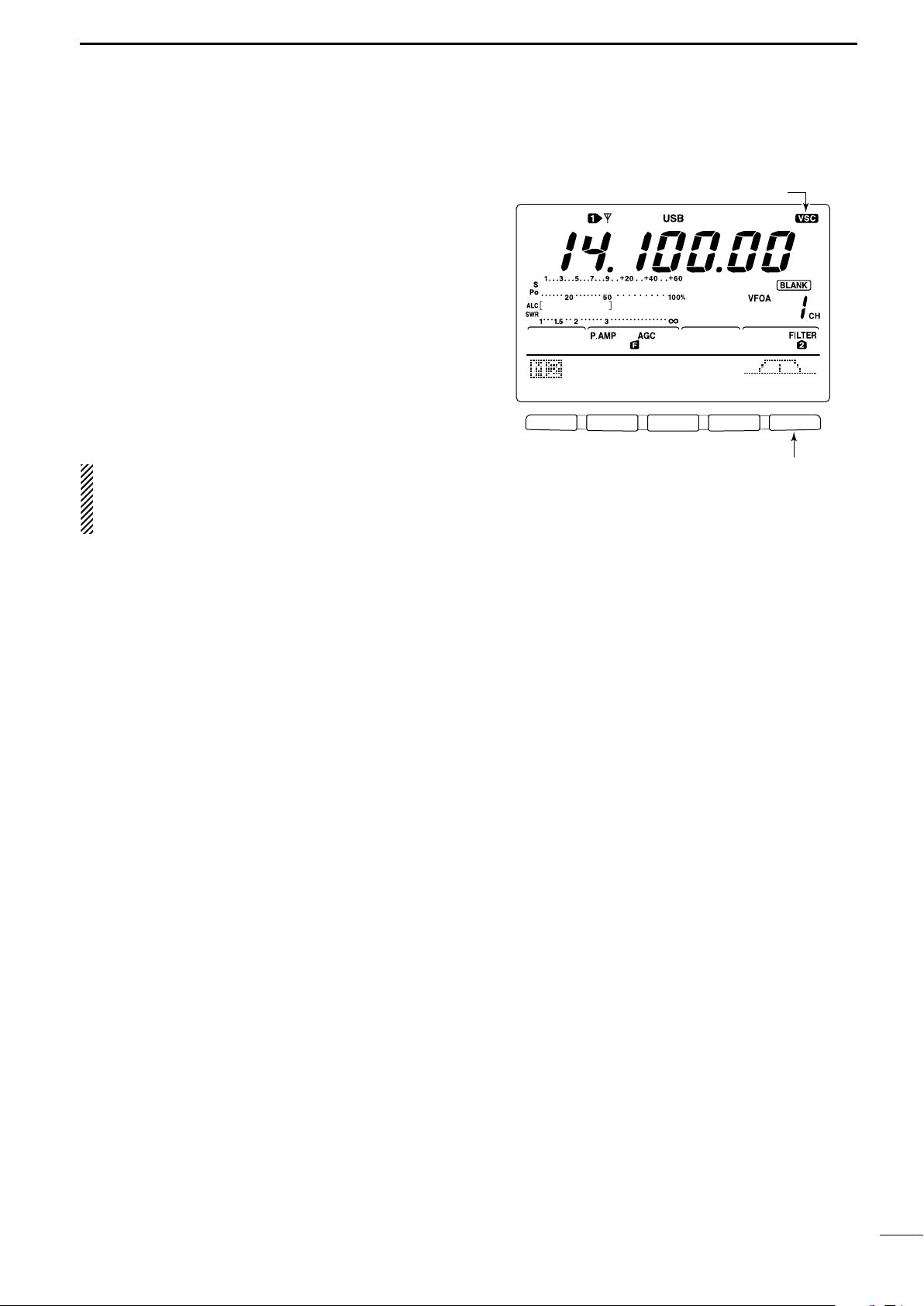
■ Voice squelch control function
F 1
F 2 F 3 F 4 F 5
SCN MEM SWR TCN VSC
Push [F5] to turn the VSC function ON and OFF.
VSC indicator
This function is useful when you don’t want unmodulated signals. When the voice squelch control function
is activated, the receiver checks received signals for
voice components.
If a receiver signal includes voice components, and the
tone of the voice components changes within 1 sec.,
squelch opens. If the received signal includes no voice
components or the tone of the voice components does
not change within 1 sec., squelch closes.
➥ While M2 is selected with [MENU], push [F5 VSC]
to switch the VSC (Voice Squelch Control) function
ON and OFF.
•“VSC” appears when the function is activated.
•The VSC function activates for phone modes
(SSB, AM and FM).
•The VSC function can also be used for scanning
operation in AM or FM mode (p. 70).
FUNCTIONS FOR RECEIVE
5
54
Page 68

6
AGC DUP CMP TBW SCP
[VOX/BK-IN]
Appears
F 1
F 2 F 3 F 4 F 5
F 1
F 2 F 3 F 4 F 5
F 1
F 2 F 3 F 4 F 5
VOX Gain
5O%
Shows VOX gain level
1
Anti-VOX
5O%
Shows anti-VOX gain level
2
VOX Delay
O.2s
Shows VOX delay time
3
FUNCTIONS FOR TRANSMIT
■ VOX function
The VOX (Voice-Operated Transmission) function
switches between transmit and receive with your voice.
This function provides an opportunity to input log entries into your computer, etc., while operating.
• Using the VOX function
q Select a phone mode (SSB, AM, FM).
w Push [VOX/BK-IN] to turn the VOX function ON or
OFF.
DD
Adjusting the VOX function
q Select a phone mode (SSB, AM, FM).
w Push [VOX/BK-IN] to turn VOX function ON.
e Push [VOX/BK-IN] for 1 sec. to enter VOX set
mode.
r Select the VOX Gain item using [F1 ≤] or [F2 ≥].
t While speaking into the microphone, rotate the tun-
ing dial to the point where the transceiver is continuously transmitting.
- Push [F3] for 1 sec. to select the default value.
y Push [F2 ≥] to select Anti-VOX item.
u While receiving, rotate the tuning dial to the point
where the transceiver does not switch to transmit
with the speaker output.
- Push [F3] for 1 sec. to select the default value.
i Push [F2 ≥] to select VOX Delay item.
o Adjust the VOX delay for a convenient interval be-
fore returning to receive.
- Select the VOX delay item using the tuning dial.
- Push [F3] to select the default value.
!0 Push [MENU] to return to previous indication.
55
Page 69

■ Break-in function
[VOX/BK-IN]
Break-IN Delay
Break-in indicator
Shows break-in delay time
7.5d
AGC DUP 1/4 KEY SCP
Full break-in indicator
The break-in function is used in CW mode to automatically toggle the transceiver between transmit and receive when keying. The IC-746PRO is capable for full
break-in or semi break-in.
DD
Semi break-in operation
During semi break-in operation, the transceiver selects
transmit when keying, then automatically returns to receive after a pre-set time from when you stop keying.
q Push [CW/RTTY] to select CW or CW-R mode.
w Push [VOX/BK-IN] several times to turn the semi
break-in function ON.
•“BK-IN” appears.
e Set the break-in delay time (the delay from transmit
to receive).
➥ Push [VOX/BK-IN] for 1 sec. to select break-in
delay program mode.
➥ Rotate the tuning dial to select the desired delay.
• Push [F3] for 1 sec. to select to the default value.
r Push [MENU] to return to the previous menu.
FUNCTIONS FOR TRANSMIT
6
When using a paddle, rotate [KEY SPEED] to adjust
the keying speed.
DD
Full break-in operation
During full break-in operation, the transceiver automatically selects transmit while keying and returns to receive
immediately after keying is finished.
q Push [CW/RTTY] to select CW or CW-R mode.
w Push [VOX/BK-IN] several times to turn the full
break-in function ON.
•“FBK-IN” appears.
When using a paddle, rotate [KEY SPEED] to adjust
the keying speed.
56
Page 70

6
[∂TX]
[CLEAR]
[RIT/∂TX] control
Appears
[MONITOR]
MONITOR Level
Monitor indicator
Shows monitor level
5O%
FUNCTIONS FOR TRANSMIT
■∂∂TX function
The ∂TX function shifts the transmit frequency up to
±9.99 kHz in 10 Hz steps without moving the receive
frequency.
• See #2 on p. 4 for function description.
q Push the [∂TX] switch to turn the ∂TX function ON
and OFF.
•“∂TX” and shift frequency appear when the function is
ON.
w Rotate the [RIT/∂TX] control.
• To reset the ∂TX frequency, push [CLEAR] for 1 sec.
•Push [CLEAR] momentarily to reset the ∂TX frequency
when the quick RIT clear function is ON. (p. 86)
•To add or subtract the ∂TX frequency to the displayed
frequency, push [∂TX] for 1 sec.
When RIT and ∂TX are ON at the same time, the
[RIT/∂TX] control shifts both the transmit and receive frequencies from the displayed frequency at
the same time.
DD ∂∂
TX monitor function
When the ∂TX function is ON, pushing and holding
[XFC] allows you to monitor the operating frequency directly (∂TX is temporarily cancelled).
■ Monitor function
The monitor function allows you to monitor your transmit IF signals in any mode through the speaker. Use
this to check voice characteristics while adjusting SSB
transmit tones. (p. 89) The CW sidetone functions regardless of the [MONITOR] switch setting.
q Push [MONITOR] to switch the monitor function ON
and OFF.
•“MONI” appears when the monitor function is ON.
w Set the monitor level.
➥ Push [MONITOR] for 1 sec. to select monitor pro-
gram mode.
➥ Rotate the tuning dial for the clearest audio out-
put while pushing [PTT] and speaking into the microphone.
• Push [F3] for 1 sec. to select the default value.
e Push [MENU] to return to the previous menu.
57
Page 71

■ Speech compressor
COMP Level
COMP Level
5
1
Compressor indicator
Shows compression level
COMP level zone
*The SWR meter functions as the COMP meter
when COMP meter is set to ON in the set mode.
COMP meter
ALC meter
Adjust the COMP Level with the tuning dial so
that the COMP meter does not exceed the COMP
level zone.
Adjust [MIC GAIN], so that the COMP meter does
not exceed this zone.
F 1
F 2F 3
F 4
F 5
F 1
F 2 F 3 F 4 F 5
AGC DUP CMP TBW SCP
AGC DUP CMP TBW SCP
TX
BW=WIDE
Push [F4]
Push [F4] for 1 sec. to select the transmit filter width.
The selected transmit filter width
is displayed for approx. 1 sec.
The speech compressor increases average RF output
power, improving signal strength and readability in
SSB, AM or FM.
When adjusting the compression level, it is necessary
to turn the COMP meter ON in the set mode, in advance (p. 82).
• In SSB mode
q Select USB or LSB mode and adjust [MIC GAIN] to
a suitable level.
w While M1 is selected, push [F3 CMP] to turn the
speech compressor ON.
•“COMP” appears.
e Push [F3 CMP] for 1 sec. to select compression
level set mode.
r While speaking into the microphone, rotate the tun-
ing dial, so that the COMP meter reads within the
COMP zone with your normal voice level.
• Push [F3] for 1 sec. to select the default value.
When the COMP meter peaks above the COMP
zone, your transmitted voice may be distorted.
t Push [MENU] to return to M1.
FUNCTIONS FOR TRANSMIT
6
• In AM/FM mode
q While M1 is selected, push [F3 CMP] to turn the
speech compressor ON.
•“COMP” appears.
w Push [F3 CMP] for 1 sec. and set the compression
level as “1” in advance.
e While speaking into the microphone, rotate [MIC
GAIN], so that the COMP meter does not exceed
the center dot whether you speak softly or loudly.
r While speaking into the microphone, rotate the tun-
ing dial, so that the COMP meter reads within the
COMP zone with your normal voice level.
• Push [F3] for 1 sec. to select the default value.
When the COMP meter peaks above the COMP
zone, your transmitted voice may be distorted.
t Push [MENU] to return to M1.
■
Transmit filter width selection
The transmit filter width for SSB mode can be selected
from wide, middle and narrow.
q Select USB or LSB mode.
w Push [MENU] to select M1, if necessary.
e Push [F4 TBW] for 1 sec. to select the transmission
passband width.
•One of “TX BW=WIDE,” “TX BW=MID” or “TX
BW=NAR” is displayed for approx. 1 sec.
• Transmit filter width: NAR 2.2 kHz
MID 2.4 kHz
WIDE 2.8 kHz
(SSB mode only)
58
Page 72

6
Tuning dial[XFC]
[SPLIT] Lights during split operation
[A/B]
AppearsShows transmit (VFO B) frequency
AGC DUP CMP TBW SCP
21.29OOO
Shows transmit (VFO B) frequency
Shows shift frequency and direction
AGC DUP CMP TBW SCP
+2O.OOk
• While pushing [XFC]
AGC DUP CMP TBW SCP
21.31OOO
• After setting up
FUNCTIONS FOR TRANSMIT
■ Split frequency operation
Split frequency operation allows you to transmit and
receive in the same mode on two different frequencies.
The split frequency operation is basically performed
using 2 frequencies in VFO A and VFO B.
The following is an example of setting 21.290 MHz for
receiving and 21.310 MHz for transmitting.
q Set 21.290 MHz (USB) in VFO A.
w Push [SPLIT] to turn the split function ON, then
push [A/B] for 1 sec.
•The equalized transmit (VFO B) frequency and “SPLIT”
appear on the LCD, and the [SPLIT] indicator lights.
e While pushing [XFC] rotate the tuning dial to set the
transmit frequency to 21.310 MHz.
•The transmit frequency can be monitored while pushing
[XFC].
r Now you can receive on 21.290 MHz and transmit
on 21.310 MHz.
To change the transmit and receive frequencies, push
[A/B] to exchange the VFO A and VFO B.
CONVENIENT
• Direct shift frequency input
The shift frequency can be entered directly.
q Push [F-INP].
w Enter the desired shift frequency with the digit
keys.
• 1 kHz to 1 MHz can be set.
•When you require a minus shift direction, push
[GENE • ] in advance.
e Push [SPLIT].
•The shift frequency is input in the sub readout and the
split function is turned ON.
[Example]
To transmit on 1 kHz higher frequency:
- Push [F-INP], [1.81] then [SPLIT].
To transmit on 3 kHz lower frequency:
- Push [F-INP], [GENE • ], [73] then [SPLIT].
• Split lock function
Accidentally releasing the [XFC] switch while rotating
the tuning dial changes the receive frequency. To prevent this, use both the split lock and dial lock functions to change the transmit frequency only. The split
lock function cancels the dial lock function while
pushing [XFC] during split frequency operation.
The dial lock’s effectiveness during split frequency
operation can be selected in the set mode for both
receive and transmit frequencies; or only the receive
frequency. (p. 83)
59
Page 73

■ Quick split function
Shows shift frequency and direction
AGC DUP CMP TBW SCP
+2O.OOk
• Setting the frequency while pushing [XFC]
AGC DUP CMP TBW SCP
21.31OOO
12
+O.O2OMHz
SPLIT Offset
Shows transmit frequency for split operation
13
OFF
SPLIT LOCK
[XFC] Tuning dial [LOCK/SPCH]
When you push the [SPLIT] switch for 1 sec., split frequency operation is turned ON, the undisplayed VFO
is automatically changed according to the plus/minus
shift frequency programmed in set mode (p. 83) or
equalized when 0 kHz (default value) is programmed
as the split shift frequency. Quick split operation is
turned ON by default but can be turned OFF in set
mode (p. 83).
q Suppose you are operating at 21.290 MHz (USB) in
VFO A.
w Push [SPLIT] for 1 sec.
• Split frequency operation is turned ON.
•The VFO and VFO B are equalized.
e While pushing [XFC], rotate the tuning dial to set
the frequency offset between transmit and receive.
•When [XFC] is released, the receive frequency is indicated.
FUNCTIONS FOR TRANSMIT
6
DD
Split offset frequency setting
By setting an often-used split frequency offset in advance, you can use the quick split function to select split
operation at the push of one switch.
Set the split offset frequency in advance in set mode
(p. 83, item 12). The example at right shows the split
offset is set to +0.020 MHz.
➥ Push [SPLIT] for 1 sec. to activate the quick split
function.
•The transmit frequency is offset from the receive frequency according to the offset in set mode.
DD
Split lock function
The split lock function is convenient for changing only
the transmit frequency. When the split lock function is
not used, accidentally releasing [XFC] while rotating the
tuning dial, changes the receive frequency. The split
lock function is ON by default, but can be turned OFF
in set mode.
q While split frequency operation is ON, push
[LOCK/SPCH] to activate the split lock function.
w While pushing [XFC], rotate the tuning dial to
change the transmit frequency.
•If you accidentally release [XFC] while rotating the tuning
dial, the receive frequency does NOT change.
60
Page 74

6
AGC DUP 1/4 RTY SCP
The best match is in this range.
F 1
F 2F 3
F 4
F 5
F 1
F 2 F 3 F 4 F 5
SCN MEM SWR TCN VSC
1Ok
STEP
1Ok
STEP
Push [F3]
Push [F5] to select
SWR measuring step.
Push [F3] to select number of SWR measuring steps.
Push [F1] to start
measuring.
• Measuring (after pushing [F1])
Frequency marker appears and moves after measurement.
*When mesurement point/s is/are set outside of the oper-
atable frequency band, the frequency marker flashes.
Typical display SWR varying between 1 and 2,
full scale up to SWR 4.0:1.
— 1.0:1
— 1.5:1
— 2.0:1
— 3.0:1
— 4.0:1
FUNCTIONS FOR TRANSMIT
■ Measuring SWR
The IC-746PRO has a built-in circuit for measuring antenna SWR— no external equipment or special adjustments are necessary.
The IC-746PRO can measure SWR in 2 ways— spot
measurement and plot measurement are available.
DD
Spot measurement
q Push [TUNER] to turn the antenna tuner OFF.
w Turn the COMP meter OFF.
➥ Push [MENU] for 1 sec. to enter set mode.
➥ Push [F1 ≤] or [F2 ≥] several times to select the
COMP Meter item.
➥
Rotate the tuning dial to set the COMP meter OFF.
➥ Push [MENU] to exit set mode.
e Push [CW/RTTY] several times to select RTTY
mode.
r Push [TRANSMIT] or [PTT] on the microphone.
t Rotate [RF PWR] clockwise past the 12 o’clock po-
sition for more than 30 W output power (30%).
y Read the SWR on the SWR meter.
u Push [TRANSMIT] or release [PTT] to receive.
The built-in antenna tuner matches the transmitter
to the antenna when the SWR is lower than 3:1.
DD
Plot measurement
Plot measurement allows you to measure the SWR
over an entire band.
q While M2 is selected with [MENU], push [F3 SWR].
• SWR graph screen appears.
w Rotate [RF PWR] clockwise past the 12 o’clock po-
sition for more than 30 W output power (30%).
e Set the center frequency for the SWR to be mea-
sured.
r Push [F5] for 1 sec. several times to select the de-
sired measuring step from 10, 50, 100 and 500 kHz.
t Push [F3] several times to select the desired num-
ber of measuring steps from 3, 5, 7, 9, 11 and 13
steps.
y Push [F1] to start the measuring.
u Push [TRANSMIT] or push and hold [PTT] on the
microphone to measure the SWR.
• Frequency marker, “∫,” appears below SWR graph.
• RTTY mode is automatically selected.
i When pushing [TRANSMIT] again or releasing
[PTT], the frequency marker and frequency indication move to the next frequency to be measured.
o Repeat steps u and i to measure SWR over the
entire frequency range.
!0 When the measured SWR is less than 1.5:1, the
61
antenna is well matched with the transceiver in the
measured frequency range.
Page 75

■ Memory channels
[V/M] [M-CH]
Disappears when a channel is programmed.
• During VFO mode
• During memory mode
MEMORY OPERATION
7
The transceiver has 101 memory channels (plus 1 call
channel). The memory mode is very useful for quickly
changing to often-used frequencies.
MEMORY
CHANNEL
Regular memory
channels in each memory channel.
Scan edge
memory P1, P2 each memory channel as scan Yes Yes No
channels edges for programmed scan.
Call channel C Same as regular. No Yes No
MEMORY
CHANNEL CAPABILITY
NUMBER
1–99
One frequency and one mode
One frequency and one mode in
All 101 memory channels are tuneable which means
the programmed frequency can be tuned temporarily
with the tuning dial, etc. in memory mode.
TRANSFER OVER-
TO VFO WRITING
Yes Yes Yes
■ Memory channel selection
DD
In VFO mode
q Push [V/M] to select VFO mode, if necessary, then
rotate [M-CH] to select a memory channel number.
•All memory channels including blank channels can be
selected.
•“BLANK” appears when no information has been pro-
grammed into a memory channel.
w Push [V/M] to select memory mode.
•“MEMO” and contents of the memory channel appear.
CLEAR
DD
In memory mode
q Push [V/M] to select memory mode.
w Rotate [M-CH] to select a memory channel.
•All memory channels including blank channels can be
selected.
•Memory channels can also be selected using the microphone [UP]/[DN] keys.
62
Page 76

7
[V/M] [M-CH]
[MW]
AGC DUP CMP TBW SCP
• [EXAMPLE]: Programming 7.088 MHz/LSB
into memory channel 12.
AGC DUP CMP TBW SCP
• [EXAMPLE]: Programming 21.280 MHz/USB
into memory channel 18.
[V/M] [M-CH]
[M-CL]
MEMORY OPERATION
■ Programming a memory
Memory channel programming can be preformed either in VFO mode or in memory mode.
DD
Programming in VFO mode
q Set the desired frequency and operating mode in
VFO mode.
w Rotate [M-CH] to select the desired memory chan-
nel.
•“BLANK” appears if the selected memory channel is a
blank channel (and does not have contents).
e Push [MW] for 1 sec. to program the displayed fre-
quency and operating mode into the memory channel.
•3 beeps are emitted when memory programming is successful.
DD
Programming in VFO mode
q Select the desired memory channel with [M-CH] in
memory mode.
• Memory channel contents appear in the display.
•“BLANK” appears and no frequency readout is displayed
if the selected memory channel is a blank channel (and
does not have contents).
w Set the desired frequency and operating mode in
memory mode.
•To program a blank channel, use direct frequency entry
with the keypad or memo pads, etc.
e Push [MW] for 1 sec. to program the displayed fre-
quency and operating mode into the memory channel.
•3 beeps are emitted when memory programming is successful.
■ Memory clearing
Any unnecessary memory channels can be cleared.
The cleared memory channels become blank channels.
q Select memory mode with [V/M].
w Select the desired memory channel with [M-CH].
e Push [M-CL] for 1 sec. to clear the contents.
63
•The programmed frequency and operating mode disappear.
•3 beeps are emitted when memory clearing is successful.
r To clear other memory channels, repeat steps w
and e.
Page 77

■ Selecting the call channel
[CALL]
AGC DUP CMP TON SCP
“C” appears
[V/M] [M-CH]
[MW]
AGC DUP CMP TON SCP
By default 145.00000 MHz/FM is programmed into the
call channel. However, this can be changed to suit
your operating preference. (see below)
q Push [CALL] to select the call channel.
•“C” appears.
w Push [CALL] again to return to the previous mode.
MEMORY OPERATION
7
■
Programming the call channel
The call channel is programmed in the same way regular memory channels are. It’s convenient to program
a most-often-used frequency into the call channel for
quick recall. As with memory channels, the call channel can also hold split frequencies.
q Rotate [M-CH] to select the call channel.
•“C” appears.
w Select the desired frequency and operating mode
to program into the call channel.
e Push [MW] for 1 sec. to program the displayed fre-
quency and operating mode into the call channel.
•3 beeps are emitted when memory programming is successful.
IMPORTANT!: When the call channel is selected
with the [CALL] switch, the frequency CANNOT be
changed using the tuning dial, band keys or keypad
input. However, when the call channel is selected
using [M-CH] in memory mode, the frequency CAN
be changed.
64
Page 78

7
[V/M] [M-CH]
TRANSFERRING EXAMPLE IN VFO MODE
Operating frequency : 21.320 MHz/USB (VFO)
Contents of M-ch 16 : 14.018 MHz/CW
Push [V/M] for 1 sec.
TRANSFERRING EXAMPLE IN MEMORY MODE
Operating frequency : 14.020 MHz/CW (M-ch 16)
Contents of M-ch 16 : 14.018 MHz/CW
Set the frequency
Push [V/M] for 1 sec.
then push [V/M]
MEMORY OPERATION
■ Frequency transferring
The contents of a memory channel (frequency, operating mode, etc.) can be transferred to the VFO.
Frequency transferring can be performed in either VFO
mode or memory mode.
DD
Transferring in VFO mode
This is useful for transferring programmed contents to
VFO.
q Select VFO mode with [V/M].
w Select the memory channel to be transferred with
[M-CH].
•“BLANK” appears if the selected memory channel is a
blank channel. In this case transferring is impossible.
e Push [V/M] for 1 sec. to transfer the frequency and
operating mode.
• 3 beeps are emitted.
DD
Transferring in memory mode
This is useful for transferring frequency and operating
mode while operating in memory mode.
When you have changed the frequency or operating mode in the selected memory channel:
• Displayed frequency and mode are transferred.
•Programmed frequency and mode in the memory
channel are not transferred, and they remain in the
memory channel.
q Select the memory channel to be transferred with
[M-CH] in memory mode.
• And, set the frequency or operating mode if required.
w Push [V/M] for 1 sec. to transfer the frequency and
operating mode.
•3 beeps are emitted when the transferring is successful.
•Displayed frequency and operating mode are transferred
to the VFO.
e To return to VFO mode, push [V/M] momentarily.
65
Page 79

■ Programming scan edges
[V/M]
Tuning dial
[M-CH]
[MW]
• After steps w to r
• After steps t to u
Memory channels P1 and P2 are the program scan
edges. They are used to program an upper and lower
frequency for programmed scan (p. 71). By default, P1
is programmed with 0.50000 MHz and P2 is programmed with 29.99999 MHz. If P1 and P2 are programmed with the same frequencies, programmed
scan will not proceed.
[EXAMPLE]: Programming 14.00000 MHz into P1
and 14.35000 MHz into P2.
q Push [V/M] to select VFO mode, if necessary.
w Rotate [M-CH] to select scan edge P1.
e Rotate the tuning dial to set 14.00000 MHz as the
lower frequency.
r Push [MW] for 1 sec. to program 14.00000 MHz
into scan edge P1.
• 3 beeps are emitted.
t Rotate [M-CH] to select scan edge P2.
y Rotate the tuning dial to set 14.35000 MHz as the
upper frequency.
u Push [MW] for 1 sec. to program 14.35000 MHz
into scan edge P2.
• 3 beeps are emitted.
•When programmed scan is activated (p. 71) scanning
will search the frequencies between 14.00000 MHz and
14.35000 MHz for signals.
MEMORY OPERATION
7
66
Page 80

7
[V/M]
Tuning dial
[M-CH][MENU]
F 1
F 2F 3
F 4
F 5
F 1
F 2F 3
F 4
F 5
F 1
F 2F 3
F 4
F 5
F 1
F 2F 3
F 4
F 5
F 1
F 2 F 3 F 4 F 5
SCN MEM SWR TCN VSC
EDT
(
) SEL
14.195OO
USB
ABC
DEL SPC
Push [F2 MEM]
Push [F2 MEM]
ABC
DEL SPC
DX
• During assigning a memory name
abc
DEL SPC
DX
spot
• After assigning a memory name
Input space
Delete a character
Move cursor forwards
Move cursor backwards
Selects character type
MEMORY OPERATION
■ Assigning memory names
All memory channels (including scan edges) can be
tagged with alphanumeric names of up to 9 characters
each.
[EXAMPLE]: Programming “DX spot” into memory
channel 99.
q Push [V/M] to select memory mode, if necessary.
w Rotate [M-CH] to select memory channel 99.
e Push [MENU] several times to select M2.
r Push [F2 MEM] to select the memory name screen.
t Push [F1 EDT] to edit memory channel name.
• A cursor appears and blinks.
•Memory channel names of blank channels cannot be
edited.
y Push [F1] several times to select the type of char-
acters for input.
•“ABC” inputs capital letters A to Z.
•“abc” inputs small letters a to z.
•“etc” is used to input other characters— ! # $ % & ¥ ? ”
’ ` ^ + – ✱ / . , : ; = < > ( ) [ ] { } | _ –are available.
•Use the keypad to directly input numerals, “0” to “9,” in-
cluding a decimal point.
u Rotate the tuning dial to select the first character for
input.
i Push [F2 ç] or [F3 å] to move the cursor forwards
or backwards, respectively.
•Push [F5 SPC] to input a space and [F4 DEL] to delete
the selected character.
o Repeat steps w to i to program another memory
!0 Push [MENU] to set the memory channel name and
channel’s name, if desired.
return to the memory name menu.
• Push [MENU] 1 more times to return to M2.
67
Page 81

■ Memo pads
AGC DUP CMP TBW SCP
MP-W
Erased
In this example, pushing [MP-W] enters 21.28000 MHz
USB into the top memo pad and erases the oldest
memo pad (21.34724 MHz LSB).
• Displayed frequency and mode • Stored in next available memo pad
AGC DUP CMP TBW SCP
• VFO or memory mode • Memo pads
MP-R
MP-R
The transceiver has a memo pad function to store frequency and operating mode for easy write and recall.
The memo pads are separate from memory channels.
The default number of memo pads is 5, however, this
can be increased to 10 in set mode if desired. (p. 85)
DD
Writing frequencies and operating
modes into memo pads
➥ Push [MP-W] to store the displayed frequency and
operating mode into a memo pad.
•Each push of [MP-W] stores a frequency and mode into
the next available memo pad; when you write a 6th (or
11th) frequency and operating mode, the oldest written
frequency and operating mode are automatically erased
to make room for the new settings.
MEMORY OPERATION
NOTE: Each memo pad must have its own unique
combination of frequency and operating mode;
memo pads having identical settings cannot be written.
7
DD
Recalling a memo pad
➥ Push [MP-R] to recall a memo pad.
•Each push of [MP-R] recalls a memo pad, starting from
the most recently written.
68
Page 82

8
PROGRAMMED SCAN
Repeatedly scans between two scan edge frequencies
(scan edge memory channels P1 and P2).
This scan operates in VFO mode.
SELECT MEMORY SCAN
Repeatedly scans all selected memory channels.
∂F SCAN
Repeatedly scans within ∂F span area.
This scan operates in memory mode.This scan operates in memory mode.
This scan operates in both VFO and memory modes.
Scan
Scan edge
P1 or P2
Scan edge
P2 or P1
Jump
Mch 1 Mch 5
Mch 2 Mch 3 Mch 4
Mch 6Mch 7Mch 99
MEMORY SCAN
Repeatedly scans all programmed memory channels.
Mch 1 Mch 5
Mch 2 Mch 3 Mch 4
Mch 6Mch 7Mch 99
SEL
SELSEL
SEL
SEL
SEL
SELSEL
SEL
SEL
ScanScan
–
∂F frequency +∂F frequency
Start frequency
Jump
SCANS
■ Scan types
■ Preparation
• Channels
For programmed scan:
Program scan edge frequencies into scan edge memory channels P1 and P2.
∂∂
F scan:
For
Set the ∂F span (∂F scan range) in the scan screen.
For memory scan:
Program 2 or more memory channels except scan
edge memory channels.
For select memory scan:
Designate 2 or more memory channels as select memory channels. To designate the channel as a select
memory channel, choose a memory channel, then
push [F3 SEL] in the scan screen, or push [F5 SEL]
in the memory name screen.
• Scan resume ON/OFF
You can select the scan to resume or cancel when detecting a signal, in set mode. Scan resume ON/OFF
must be set before operating a scan. See p. 70 for
ON/OFF setting and scan resume condition details.
• Scan speed
Scan speed can be selected from 2 levels, high or low,
in set mode. See p. 70 for details.
• Squelch condition
SCAN
STARTS
WITH
SQUELCH
OPEN
SQUELCH
CLOSED
PROGRAMMED
SCAN
The scan continues
until it is stopped
manually, and does
not pause even if it
detects signals.
Scan stops when detecting a signal.
If you set scan resume ON in scan set
mode, the scan pauses for 10 sec. when
detecting a signal, then resumes. When a
signal disappears while scan is paused,
scan resumes 2 sec. later.
MEMORY SCAN
Scan pauses on
each channel when
the scan resume is
ON; not applicable
when OFF.
69
Page 83

■ Voice squelch control function
F 1
F 2F 3
F 4
F 5
F 1
F 2 F 3 F 4 F 5
F 1
F 2F 3
F 4
F 5
F 1
F 2F 3
F 4
F 5
SCN MEM SWR TCN VSC
PRO
∂F
FIN SPN SET
∂
F:±1Ok
Push [F1]
Push [F5]
SCAN Speed
HIGH
1
Push [F1] or [F2]
SCAN Resume
ON
2
F 1
F 2 F 3 F 4 F 5
SCN MEM SWR TCN VSC
Push [F5] to turn the VSC function ON and OFF.
VSC indicator
This function is useful when you don’t want unmodulated signals pausing or cancelling a scan. When the
voice squelch control function is activated, the receiver
checks received signals for voice components.
If a receiver signal includes voice components, and the
tone of the voice components changes within 1 sec.,
scan pauses (or stops). If the received signal includes
no voice components or the tone of the voice components does not change within 1 sec., scan resumes.
➥ While M2 is selected with [MENU], push [F5 VSC]
to switch the VSC (Voice Squelch Control) function
ON and OFF.
•“VSC” appears when the function is activated.
• The VSC function activates for any scan.
•The VSC function resumes the scan on unmodu-
lated signals, regardless of whether the scan resume condition is set to ON or OFF.
SCANS
8
■ Scan set mode
When the squelch is open, scan continues until it is
stopped manually— it does not pause on detected signals. When squelch is closed, scan stops when detecting a signal, then resumes according to the scan
resume condition. Scan speed and the scan resume
condition can be set using the scan set mode.
q Push[MENU] to select M2.
w Push [F1 SCN] to select scan menu.
e Push [F5 SET] to select scan set mode.
r Push [F1 ≤] or [F2 ≥] to select SCAN Speed
item.
t Rotate the tuning dial to select scan speed from
high and low.
•“HIGH” : scan is faster
•“LOW” : scan is slower
y Push [F2 ≥] to select SCAN Resume item.
u Rotate the tuning dial to select scan resume func-
tion from ON and OFF.
•“ON” : when detecting a signal, scan pauses for
10 sec., then resumes. When a signal disap-
•“OFF” : when detecting a signal, cancels scanning.
i Push [MENU] to return to scan menu.
pears, scan resumes 2 sec. later.
70
Page 84

8
[TS]
Tuning dial
[MENU]
[V/M]
Mode keys
F 1
F 2F 3
F 4
F 5
F 1
F 2 F 3 F 4 F 5
F 1
F 2F 3
F 4
F 5
SCN MEM SWR TCN VSC
PRO
∂F
FIN SPN SET
∂
F:±1Ok
PRO
∂F
FIN SPN SET
PROG
SCAN
Push [F1]
Push [F1] to start/cancel the scanning.
Push [F1]
F 1
F 2F 3
F 4
F 5
F 1
F 2F 3
F 4
F 5
PRO
∂F
FIN SPN SET
PROG
SCAN
PRO
∂F
FIN SPN SET
F-PROG
SCAN
Push [F3] to switch
between programmed
scan and fine programmed scan.
SCANS
■ Programmed scan/Fine programmed scan (VFO mode)
Programmed scan searches for signals between scan
edge memory channels P1 and P2. The default frequencies for these memories are 0.500000 MHz and
29.99999 MHz, respectively. See p. 66 for scan edges
programming.
q Push [V/M] to select VFO mode, if necessary.
w Select the desired operating mode.
•The operating mode can also be changed while scanning.
e Push [TS] to select a tuning step.
• The tuning step can also be changed while scanning.
r Push [MENU] to select M2.
t Push [F1 SCN] to select the scan menu.
• See p. 69 for scan condition.
•If the [RF/SQL] control function is set as “AUTO,” the
squelch is always open in SSB, CW and RTTY modes.
y Push [F1 PRO] to start the programmed scan.
• The MHz and kHz decimal points blink while scanning.
u When the scan detects a signal, the scan stops,
pauses or ignores it depending on the resume, VSC
setting and the squelch condition.
i To cancel the scan, push [F1 PRO].
•Rotating the tuning dial during scan also cancels scan
operation.
If the same frequencies are programmed into the
scan edge memory channel P1 and P2, programmed scan does not start.
DD
During programmed scan, when a signal is received,
scan continues, but the tuning step is temporarily set to
10 Hz.
q Follow steps q to y above to start programmed
w During programmed scan, push [F3 FIN] to switch
e Push [F1 PRO] to cancel the scan.
71
About the Fine programmed scan
scan.
between programmed scan and fine programmed
scan operation.
•Rotating the tuning dial during scan also cancels scan
operation.
Page 85

■ Memory scan operation (Memory mode)
Tuning dial[MENU]
[V/M]
F 1
F 2F 3
F 4
F 5
MEM
∂F
SEL SPN SET
MEMO
SCAN
Push [F1] to start/cancel the scanning.
F 1
F 2F 3
F 4
F 5
F 1
F 2F 3
F 4
F 5
MEM
∂F
SEL SPN SET
MEMO
SCAN
MEM
∂F
SEL SPN SET
SEL-MEMO
SCAN
Push [F3] to switch
between memory scan
and select memory
scan.
F 1
F 2F 3
F 4
F 5
F 1
F 2F 3
F 4
F 5
∂
F:±1Ok
MEM
∂F
SEL SPN SET
Push [F3] to set/cancel as a select channel.
Select memory inidcator
Push [F3] to set/cancel as a select channel.
EDT (
) SEL
14.195OO
USB
• Scan menu
• Memory name screen
Memory scan searches through memory channel 1 to
99 for signals. Blank (unprogrammed) memory channels are skipped.
q Push [V/M] to select memory mode, if necessary.
w Push [MENU] to select M2.
e Push [F1 SCN] to select the scan menu.
• See p. 69 for scan condition.
•If the [RF/SQL] control function is set as “AUTO,” the
squelch is always open in SSB, CW and RTTY modes.
r Push [F1 MEM] to start the memory scan.
• The MHz and kHz decimal points blink while scanning.
•At least 2 memory channels must be programmed for
memory scan to proceed.
t To cancel the scan, push [F1 MEM].
•Rotating the tuning dial during scan also cancels scan
operation.
SCANS
8
■ Select memory scan
Select memory scan searches through memory channels set as “select,” for signals. See below for setting
and deleting select memory channels.
q Follow the steps q to r above to start memory
scan.
w During memory scan, push [F3 SEL] to switch be-
tween memory scan and select memory scan.
•At least 2 memory channels must be set as the select
channel.
e Push [F1 MEM] to cancel the scan.
•Rotating the tuning dial during scan also cancels scan
operation.
DD
Setting/Cancelling select memory channels
All memory channels, except scan edges (P1 and P2),
can be set as a select memory channels.
➥ While the scan menu is selected, push [F3 SEL] to
set/cancel the displayed memory channel as a select channel; or while memory name screen is indicated, push [F5 SEL] to set/cancel the displayed
memory channel as a select memory channel.
•“SEL” appears when the channel is set as a select mem-
ory channel.
•“SEL” disappears when cancelled.
•Push [F3 SEL]/[F5 SEL] for 1 sec to cancel all select
memory settings.
72
Page 86

8
Keypad
Tuning dial
[MENU]
[V/M]
F 1
F 2F 3
F 4
F 5
F 1
F 2 F 3 F 4 F 5
F 1
F 2F 3
F 4
F 5
SCN MEM SWR TCN VSC
PRO
∂F
FIN SPN SET
∂
F:±1Ok
PRO
∂F
FIN SPN SET
∂
F SCAN
Push [F1]
Push [F2] to start/cancel the scanning.
Push [F2]
Push [F4] to select the span.
F 1
F 2F 3
F 4
F 5
F 1
F 2F 3
F 4
F 5
PRO
∂F
FIN SPN SET
∂
F SCAN
PRO
∂F
FIN SPN SET
F-
∂
F SCAN
Push [F3] to switch
between programmed
scan and fine programmed scan.
SCANS
■∂∂F scan operation and Fine ∂F scan
∂F scan searches for signals within the specified
range with the displayed VFO or memory channel frequency as for center frequency. The frequency range
is specified by the span.
q Push [V/M] to select VFO mode or memory mode,
as desired.
w Set center frequency of the ∂F scan.
e Push [MENU] to select M2.
r Push [F1 SCN] to select the scan menu.
• See p. 69 for scan condition.
•If the [RF/SQL] control function is set as “AUTO,” the
squelch is always open in SSB, CW and RTTY modes.
t Set the ∂F span by pushing [F4 SPN].
•±5 kHz, ±10 kHz, ±20 kHz, ±50 kHz, ±100 kHz,
±500 kHz and ±1 MHz are selectable.
y Push [F2 ∂F] to start the ∂F scan.
• Decimal points blink while scanning.
u When the scan detects a signal, the scan stops,
pauses or ignores it depending on the VSC, resume
setting and the squelch condition.
i Push [F2 ∂F] to cancel the ∂F scan.
•Rotating the tuning dial during scan also cancels scan
operation.
DD
During ∂F scan, when a signal is received, scan continues, but the tuning step is temporarily set to 10 Hz.
q Follow steps q to y above to start programmed
w During ∂F scan, push [F3 FIN] to switch between
About the Fine ∂∂F scan
scan.
∂F scan and fine ∂F scan operation.
e Push [F2 ∂F] to cancel the scan.
73
•Rotating the tuning dial during scan also cancels scan
operation.
Page 87

■ Tone scan/DTCS code scan operation
F 1
F 2 F 3 F 4 F 5
F 1
F 2 F 3 F 4 F 5
F 1
F 2 F 3 F 4 F 5
F 1
F 2 F 3 F 4 F 5
F 1
F 2 F 3 F 4 F 5
AGC DUP CMP TON SCP
TON
SCN
88.5Hz
Rptr Tone
TON SCN
88.5Hz
Rptr Tone SCAN
Push [F4] for 1 sec.
Push [F1] several times to select tone type.
• Repeater tone scan
• Tone squelch tone scan
• DTCS code scan
TON SCN
88.5Hz
TSQL Tone SCAN
TON SCN
O23-NN
DTCS Code SCAN
Push [F2] to start/cancel the scan.
Push [F2] to start/cancel the scan.
Push [F2] to start/cancel the scan.
Push [F1] several times to select polarity.
By monitoring a signal that is being operated with a repeater, tone squelch or DTCS, you can determine the
tone frequency necessary to open a repeater or the
squelch.
q Push [AM/FM] to select FM mode.
w Push [MENU] several times to select M1.
e Push [F4 TONE] for 1 sec. to enter tone set mode.
r Push [F1 TON] to select the tone type to be
scanned.
•“Rptr Tone” for repeater tone, “TSQL Tone” for
tone squelch and “DTCS Code” for DTCS code can be
selected.
•When selecting DTCS code to be scanned, push [F5]
several times to select the DTCS code polarity.
“NN” : Normal polarity for both transmit and receive.
“NR” : Normal polarity for transmit and reverse polarity
for receive.
“RN” : Reverse polarity for transmit and normal polarity
for receive.
“RR” : Reverse polarity for both transmit and receive.
t Push [F2 SCN] to start the tone scan function.
•“Rptr Tone SCAN,” “TSQL Tone SCAN” or
“DTCS Code SCAN” blinks when repeater tone scan,
tone squelch scan or DTCS code scan is operated, respectively.
y When a matched tone or code is found, the scan
pauses and the tone frequency or code is set for the
selected tone as in step r.
When the tone scan or DTCS code scan is operated
in memory or call channel mode, the detected tone frequency or code can be used temporarily.
To keep the detected tone frequency or code setting
for memory contents, you must over-write the memory
or call channel.
u Push [F2 SCN] to cancel the tone scan function.
•Rotating the tuning dial during scan also cancels scan
operation.
SCANS
8
74
Page 88

9
ANTENNA TUNER OPERATION
■ Antenna connection and selection
The IC-746PRO has 2 antenna connectors for the
HF/50 MHz bands, [ANT1] and [ANT2], and 1 antenna
connector for the 144 MHz band; a total of 3 antenna
connectors.
For each operating band the IC-746PRO covers, there
is a band memory which can memorize a selected antenna. When you change the operating frequency beyond a band, the previously used antenna is automatically selected (see below) for the new band. This
function is convenient when you use 2 antennas for HF
and 50 MHz bands operation.
• Antenna select function: “Auto”
Once an antenna has been selected for use with a
band by pushing [ANT], the antenna is automatically
selected whenever that band is accessed.
[ANT]
144 MHz 21/28/50 MHz 3.5/7 MHz
[EXAMPLE]: a 3.5/7 MHz antenna is connected to
[ANT1], a 21/28/50 MHz antenna is connected to
[ANT2]. When the antenna selector function is set to
“Auto,” an antenna is automatically selected when
changing bands.
• Antenna select function: “Manual”
When “Manual” is selected, you can use the [ANT1]
and [ANT2], however, band memory does not function. In this case you must select an antenna manually. However, the 144 MHz antenna will still be
selected automatically.
[EXAMPLE]: an optional antenna tuner and HF antenna are connected to [ANT1] and a 50 MHz antenna is connected to [ANT2].
[ANT1][ANT2]
144 MHz band 50 MHz band HF bands
AH-4
[ANT1][ANT2]
• Antenna select function: “OFF”
In this case, only [ANT1] and the 144 MHz antenna
connector can be used. [ANT] switch does not function.
75
Page 89

■ Antenna tuner operation
[TUNER]
The internal automatic antenna tuner matches the
transceiver to the connected antenna automatically.
Once the tuner matches an antenna, the variable capacitor angles are memorized as a preset point for each
frequency range (100 kHz steps). Therefore, when you
change the frequency range, the variable capacitors are
automatically preset to the memorized point.
CAUTION: NEVER transmit with the tuner ON
when no antenna is connected. This will damage
the transceiver. Be careful of the antenna selection.
DD
TUNER OPERATION
➥ Push [TUNER] to turn the internal antenna tuner
ON. The antenna is tuned automatically when the
antenna SWR is higher than 1.5:1.
• When the tuner is ON, the “TUNE” indicator appears.
• MANUAL TUNING
During SSB operation at low voice levels, the internal
tuner may not be tuned correctly. In such cases, manual tuning is helpful.
➥ Push [TUNER] for 1 sec., to start manual tuning.
•A side tone is emitted and “TUNE” indicator blinks while
tuning.
•If the tuner cannot reduce the SWR to less than 1.5:1
after 20 sec. of tuning, the [TUNER] switch indicator
goes out.
• AUTOMATIC TUNER START (HF bands only)
If you want to deactivate the tuner under conditions
of VSWR 1.5:1 or less, use the auto tuner start function and turn the tuner OFF. This function activates
the tuner automatically when the SWR exceeds 1.5:1.
This function is turned ON in set mode. (p. 84).
• PTT TUNER START
The tuner is always tuned when the PTT is pushed
after the frequency is changed (more than 1% from
last-tuned frequency). This function removes the
“push and hold [TUNER]” operation and activates for
the first transmission on a new frequency.
This function is turned ON in set mode. (p. 84).
• Antenna tuner of the IC-PW1
When using an external antenna tuner such as the
IC-PW1’s tuner, tune with the external antenna tuner,
while the internal tuner is turned OFF. After tuning is
completed, turn the internal tuner ON. Otherwise,
both tuners tune simultaneously and correct tuning
may not be obtained.
See the instruction manual included with each antenna tuner for their respective operations.
ANTENNA TUNER OPERATION
NOTES:
•The internal antenna tuner can only tune the HF and
50 MHz bands— the 144 MHz band cannot be tuned.
•NEVER transmit without an antenna properly connected
to antenna port in use.
•When 2 antennas are connected, select the antenna to
be used with [ANT].
•If the SWR is higher than about 1.5:1 when tuning above
100 kHz on an antenna’s preset point, push [TUNER] for
1 sec. to start manual tuning.
•The internal tuner may not be able to tune in AM mode. In
such cases, push [TUNER] for 1 sec. to manually tune.
DD
If the tuner cannot tune the antenna
Check the following and try again:
• the [ANT] connector selection.
• the antenna connection and feedline.
•the unaltered antenna SWR.
Less than 2.5:1 for 50 MHz band)
•the transmit power. (8 W for HF bands; 15 W for 50 MHz
band)
• the power source voltage/capacity.
(Less than 3:1 for HF bands;
If the tuner cannot reduce the SWR to less than 1.5:1
after checking the above, perform the following:
• repeat manual tuning several times.
• tune with a 50 Ω dummy load and re-tune the antenna.
• turn power OFF and ON.
•adjust the antenna cable length.
(This is effective for higher frequencies in some cases.)
•Some antennas, especially for low bands, have a nar-
row bandwidth. These antennas may not be tuned at the
edge of their bandwidth, therefore, tune such an antenna as follows:
[Example]: Suppose you have an antenna which has an
SWR of 1.5:1 at 3.55 MHz and an SWR of 3:1 at 3.8 MHz.
q Push [TUNER] to turn the antenna tuner ON.
w Select CW mode.
e Turn OFF the break-in function. (p. 56)
r Push [TRANSMIT] to set to the transmit condition.
t Set 3.55 MHz and key down.
y Set 3.80 MHz and key down.
u Push [TRANSMIT] to return to the receive condition.
9
76
Page 90

9
For mobile operation
For outdoor operation
Long wire
Optional AH-2b
antenna element
[TUNER]
Coaxial cable (from AH-4)
ANT1
Transceiver
Ground
AH-4
Control cable
Long wire or optional AH-2b
ANTENNA TUNER OPERATION
■ Optional external tuner operation
DD
AH-4 HF/50 MHz AUTOMATIC ANTENNA TUNER
The AH-4 matches the IC-746PRO to a long wire antenna more than 7 m/23 ft long (3.5 MHz and above).
•See the AH-4 instruction manual for AH-4 installation and
antenna connection details.
NEVER operate the AH-4 without an antenna wire.
The tuner and transceiver will be damaged.
NEVER operate the AH-4 when it is not grounded.
Transmitting before tuning may damage the transceiver. Note that the AH-4 cannot tune when using a
1
⁄2 λ long wire or multiple of the operating frequency.
When connecting the AH-4, the antenna connector
assignments are [ANT2] for the internal tuner and
[ANT1] for the AH-4. The antenna indicator in the
LCD displays “EXT” when the AH-4 is connected
and selected.
DD
AH-4 operation
Tuning is required for each frequency. Be sure to
re-tune the antenna before transmitting when you
change the frequency— even slightly.
AH-4 setting example:
R WARNING: HIGH VOLTAGE!
NEVER touch the antenna element while tuning or
transmitting.
q Set the desired frequency in an HF or 50 MHz
band.
•The AH-4 may not operate on frequencies outside of
ham bands.
w Push [TUNER] for 1 sec.
•“TUNER” blinks while tuning.
e “TUNE” appears constantly when tuning is com-
plete.
•When the connected wire cannot be tuned, the “TUNE”
indicator goes out, and the AH-4 is bypassed. At that
point the antenna wire connection root is to the transceiver directly, and not via AH-4 antenna tuner.
r
To bypass the AH-4 manually, push [TUNER].
• Connecting the AH-4
77
Page 91

■ Connections
■ When connecting to [DATA]
• When using a PC application
• When using a TNC
q DATA IN
w GND
r DATA OUT (9600 bps)
y P SQL*
t AF OUT (1200 bps)
e PTT P
TX AUDIO
GND
RX AUDIO
SQL
PTT
q DATA IN
w GND
r DATA OUT (9600 bps)
y P SQL*
t AF OUT (1200 bps)
e PTT P
TX AUDIO
GND
TNC
PC
RS-232C
RX AUDIO
SQL
PTT
Connect to serial port, parallel
port, speaker jack, microphone
jack and line IN/OUT jack, etc.
See the instruction manual of the
application for details.
*When connecting the squelch line, consult the necessary manual (TNC, etc.)
DATA COMMUNICATION
10
■ When connecting to [ACC(1)]
• When using a PC application
RTTY
2
4
5
3
1
8
6
7
GND
AF
SEND
• When using a TNC
RTTY
2
4
1
8
6
Rear panel view
GND
5
AF
3
SEND
7
■ When connecting to [MIC]
• When using a PC application
MIC INPUT
AF OUTPUT
• When using a TNC
MIC GND
GND
PTT*
MIC INPUT
AF OUTPUT
MIC GND
GND
RTTY OUTPUT
GND
AUDIO INPUT
PTT
RTTY OUTPUT
GND
AUDIO INPUT
PTT
AUDIO OUTPUT
AF INPUT
GND
PTT*
AFSK OUTPUT
AF INPUT
GND
Connect to serial port, parallel
port, speaker jack, microphone
jack and line IN/OUT jack, etc.
See the instruction manual of the
application for details.
TNC or scan converter
Connect to serial port, parallel
port, speaker jack, microphone
jack and line IN/OUT jack, etc.
See the instruction manual of the
application for details.
TNC or scan converter
PC
RS-232C
PC
RS-232C
PTT*
SQL
PTT*
SQL INPUT
*When using the VOX function, no need to connect. Refer to the instruction
manual of the external equipment (TNC, etc.).
When connecting the squelch line, consult the necessary manual (TNC, etc.).
78
Page 92

10
Band keys[TX] indicator[TRANSMIT]
[MIC GAIN] [AM/FM] Tuning dial
Selected mode indicator appears
[SSB]
• Example— LSB/LSB data mode
Mark freq.: 2125 Hz
Shift freq.: 200 Hz
2325 Hz
200 Hz 2125 Hz
Carrier point
(Displayed frequency)
DATA COMMUNICATION
■ Packet (AFSK) operation
Before operating packet (AFSK) be sure to consult the
operating manual that came with your TNC.
q Connect a TNC and PC. (p. 78)
w Push a band key to select an operating band.
e Push [SSB] or [AM/FM] to select the desired operat-
ing mode.
•After LSB or USB is selected, push [SSB] for 1 sec. to
select LSB data or USB data mode, or after AM or FM is
selected, push [AM/FM] for 1 sec. to select AM data or
FM data mode.
•Generally, LSB is used on HF bands and FM is used for
packet operation on the VHF band.
r Rotate the tuning dial to tune the desired signal.
t Transmit your AFSK signals using your computer’s
keyboard.
• Rotate [RF PWR] to set the output power.
•Relative strength of the transmitted signal is indicated in
the Po meter while operating the TNC.
•When operating in SSB (data) mode, adjust output
power so that the ALC reading in the ALC meter stays
in the ALC zone.
NOTE: When connecting a TNC to the ACC socket
on the rear panel, select SSB (LSB/USB) data mode
or disconnect the microphone and rotate [MIC
GAIN] fully counterclockwise.
When SSB data mode is selected, the audio input
from the [MIC] connector is automatically cut, and
the audio input from the [ACC(1)] is used.
Also, when the SSB data mode is selected, the fixed
setting listed below are selected automatically;
• Speech compressor : OFF
• Transmit bandwidth : MID
• Tx tone (Bass) : 0
• Tx tone (Treble) : 0
DD
Frequency indication during AFSK operation
When operating AFSK in SSB mode, the indicated frequency is the signals carrier point.
79
Page 93

■ Adjusting the TNC output level
21
ON
96OObps Mode
21
OFF
96OObps Mode
Select with the tuning dial
When setting data transmission speed to 9600 bps,
the data signal coming from the TNC is applied exclusively to the internal limiter circuitry to automatically
maintain band width.
NEVER apply data levels from the TNC of over 0.6 V
p-p, otherwise the transceiver will not be able to maintain the band width and may possibly interfere with
other stations.
DD
Using with a level meter or synchroscope
When using a level meter or synchroscope, adjust the
TX audio output level (DATA IN level) from the TNC as
follows.
0.4 V p-p (0.2 Vrms) : recommended level
0.2–0.5 V p-p (0.1–0.25 Vrms) : acceptable level
DD
Not using a measuring device
q Connect the transceiver to a TNC. (p. 78)
w Enter a test mode (“CAL,” etc.) on the TNC, then
transmit some test data.
e When the transceiver fails to transmit the test data
or transmits sporadically (TX indicator doesn’t light
or flashes):
-Decrease the TNC output level until the transmit
indicator lights continuously.
When transmission is not successful even though
the TX indicator lights continuously:
- Increase the TNC output level.
DATA COMMUNICATION
10
■ Data transmission speed
For data communication (in FM mode), the transceiver
can be set to to a maximum data speeds of 9600 bps
(or less; 1200, 2400 or 4800 bps).
q Push [MENU] for 1 sec. to enter set mode.
w Push [F1 ≤] or [F2 ≥] to select the 9600bps
Mode item.
e Rotate the tuning dial to turn the 9600 bps mode ON
and OFF.
ON : 9600 bps of data speed
OFF : 1200, 2400 or 4800 bps of data speed
(default)
r Push [MENU] to return to previous indication.
80
Page 94

11
LCD Backlight
5O%
2
LCD Contrast
5O%
1
Beep Level
3
5O%
Beep Level-lmt
4
ON
Cal. Marker
5
OFF
SET MODE
■ General set mode
DD
Entering set mode
Set mode is used for programming infrequently
changed values or conditions of functions.
• Set mode operation
q Push [MENU] several times to select the function
menu indication, if necessary.
w Push [MENU] for 1 sec. to enter the set mode.
e Push [F1 ≤] or [F2 ≥] to select the desired item.
r Set the desired condition using the tuning dial.
•Push [F3] for 1 sec. to select a default condition or value.
t Push [MENU] to exit the set mode.
DD
Set mode items
1. LCD Contrast
This item adjusts the contrast of the LCD from 0% to
100% in 1% steps.
(default: 50%)
2. LCD Backlight
This item adjusts the brightness of the LCD from 0%
to 100% in 1% steps.
(default: 50%)
[F1 ≤]
[F2 ≥]
Tuning dial[MENU]
3. Beep Level
This item adjusts the volume level for confirmation
beep tones from 0% to 100% in 1% steps. When the
beep tones, item 6. Beep (p. 82), are turned OFF,
this setting has no effect.
(default: 50%)
4. Beep Level-lmt
This item allows you to set a maximum volume level
for confirmation beep tones. Confirmation beep tones
are linked to the [AF] control until a specified volume
level is reached— further rotation of the [AF] control
will not increase the volume of the beep tones.
ON Confirmation beep ON (default)
OFF Confirmation beep OFF
5. CAL. Marker
This item is used for a simple frequency check of the
transceiver.
ON Calibration marker ON
OFF Calibration marker OFF (default)
See p. 94 for calibration procedure.
Turn the calibration marker OFF after checking the
frequency of the transceiver.
81
Page 95

Beep
6
ON
Band Edge Beep
7
ON
RF/SQL Control
8
RF+SQL
Meter Peak Hold
9
ON
1
O OFF
COMP Meter
■ General set mode (continued)
6. Beep
A beep sounds each time a switch is pushed to confirm it. This function can be turned OFF for silent operation.
ON Confirmation beep ON (default)
OFF Confirmation beep OFF
The volume level can be set in 3. Beep Level.
(p. 81)
7. Band Edge Beep
A beep sounds when an operating frequency enters
or exits an amateur band. This functions independent
of the confirmation beep setting (above).
ON Band edge beep ON (default)
OFF Band edge beep OFF
SET MODE
11
The volume level can be set in 3. Beep Level.
(p. 81)
8. RF/SQL Control
The [RF/SQL] control can be set as the RF/squelch
control (default), the squelch control only (RF gain is
fixed at maximum) or ‘Auto’ (RF gain control in SSB,
CW and RTTY; squelch control in AM and FM).
RF+SQL [RF/SQL] control as RF/squelch con-
trol (default)
SQL [RF/SQL] control as squelch control
AUTO [RF/SQL] control as RF gain control
in SSB, CW and RTTY; squelch control in AM and FM
9. Meter Peak Hold
This item turns the meter peak hold function ON and
OFF. When set to ON (default), peak meter readings
are displayed for about 0.5 sec.
10. COMP Meter
This item turns the COMP meter indication ON and
OFF during transmit. When set to ON, the COMP
meter is displayed instead of the SWR meter.
(default: OFF)
82
Page 96

11
11
ON
Quick SPLIT
12
O.OOOMHz
SPLIT Offset
13
OFF
SPLIT LOCK
14
O.1OOMHz
DUP Offset
HF
15
O.5OOMHz
DUP Offset
5OM
16
O.6OOMHz
DUP Offset 144M
SET MODE
■ General set mode (continued)
11. Quick SPLIT
When this item is set to ON, pushing [SPLIT] for 1
sec. sets the transmit frequency using the displayed
frequency and the split offset, set in SPLIT Off-
set item below, and activates the split function automatically.
ON Quick split ON (default)
OFF Quick split OFF
12. SPLIT Offset
This item sets the offset (difference between transmit
and receive frequencies) for the quick split function.
The offset frequency can be set from –9.999 MHz to
+9.999 MHz in 1 kHz steps.
13. SPLIT LOCK
When this item is ON, the tuning dial can be used to
adjust the transmit frequency while pushing [XFC]
even while the dial lock function is activated.
ON Split lock function ON
OFF Split lock function OFF (default)
14. DUP Offset HF
This item sets the offset (difference between transmit
and receive frequencies) for duplex operation. However, this setting is used to input the repeater offset
for an HF band only.
The offset frequency can be set from 0.000 MHz to
9.999 MHz in 1 kHz steps.
15. DUP Offset 50M
This item sets the offset (difference between transmit
and receive frequencies) for duplex operation. However, this setting is used to input the repeater offset
for a 50 MHz band only.
The offset frequency can be set from 0.000 MHz to
9.999 MHz in 1 kHz steps.
16. DUP Offset 144M
This item sets the offset (difference between transmit
and receive frequencies) for duplex operation. However, this setting is used to input the repeater offset
for a 144 MHz band only.
The offset frequency can be set from 0.000 MHz to
9.999 MHz in 1 kHz steps.
83
Page 97

17
DUP-
One Touch Rptr
18
ON-1
Auto Repeater
19
OFF
Auto Tune
2O
OFF
PTT Tune
21
OFF
96OObps Mode
■ General set mode (continued)
17. One Touch Rptr
This item turns the one touch repeater function ON
(DUP- or DUP+) and OFF.
When [F2 DUP] is pushed for 1 sec. in M1, the selected offset direction and the programmed duplex
offset frequency (depending on the operating frequency band) is set with the displayed frequency.
18. Auto Repeater
This item turns the auto repeater function to ON-1
(auto duplex setting), ON-2 (auto duplex setting and
activating tone encoder) or OFF.
See p. 46 for details concerning the auto repeater
function.
SET MODE
11
19. Auto Tune
The internal antenna tuner has an automatic start capability which starts tuning if the SWR is higher than
1.5–3:1 in the HF bands.
When “OFF” is selected, the tuner remains OFF even
when the SWR is poor (1.5–3:1). When “ON” is selected, automatic tune starts even when the tuner is
turned OFF.
20. PTT Tune
Tuning of the internal or external antenna tuner can
be started automatically at the moment the PTT is
pushed after the operating frequency is changed
(more than 1% from the last-tuned frequency).
21. 96OObps Mode
This item turn the 9600 bps data transmission capability ON and OFF.
ON : For 9600 bps data transmission.
OFF : For the regular audio (or slower data)
transmission only.
84
Page 98

11
22
Auto
[ANT] Switch
23
English
SPEECH Language
24
HIGH
SPEECH Speed
25
ON
SPEECH S-Level
26
5
Memory Pad Ch
SET MODE
■ General set mode (continued)
22. [ANT] Switch
You can set the antenna connector selection to automatic, manual or non-selection (when using 1 antenna only for the HF/50 MHz bands).
Auto : The antenna switch is activated and
the band memory memorizes the selected antenna. (default)
Manual: The antenna switch is activated and
selects an antenna manually.
OFF : The antenna switch is not activated
and does not function. The [ANT1] connector is always selected in this case.
23. SPEECH Language
When the optional UT-102
installed, you can select between English and Japanese as the language.
VOICE SYNTHESIZER UNIT
is
English : Announces in English (default)
Japanese : Announces in Japanese
See p. 90 for unit installation.
24. SPEECH Speed
When the optional UT-102
installed, you can select between faster or slower
synthesizer output.
HIGH : Announces faster (default)
LOW : Announces slower
See p. 90 for unit installation.
VOICE SYNTHESIZER UNIT
25. SPEECH S-Level
When the optional UT-102
installed, you can have frequency, mode and signal
level announcement. Signal level announcement can
be deactivated if desired.
ON : Announces operating frequency, mode
and receiving signal level. (default)
OFF : Announces operating frequency and
mode only.
VOICE SYNTHESIZER UNIT
is
is
See p. 90 for unit installation.
26. Memory Pad Ch
This item sets the number of memo pad channels
available. 5 or 10 memo pads can be set.
5 : 5 memo pads (default)
10: 10 memo pads
85
Page 99

27
HIGH
DIAL Auto TS
28
HIGH
MIC U/D Speed
29
OFF
Quick RIT Clear
3O
ON
BW Popup (PBT)
31
ON
BW Popup (FIL)
■ General set mode (continued)
27. DIAL Auto TS
This item sets the auto tuning step function. When rotating the tuning dial rapidly, the tuning step automatically changes several times as selected.
There are 2 type of auto tuning steps: HIGH (Fastest)
and LOW (Faster).
HIGH : Auto tuning step is turned ON.
Approx. 5 times fastest tuning step
during rapid rotation (default)
LOW : Auto tuning step is turned ON.
Approx. 2 times faster tuning step during rapid rotation
OFF : Auto tuning step is turned OFF.
28. MIC U/D Speed
This item sets the rate at which frequencies are
scanned when the microphone [UP]/[DN] switches
are pushed and held. High or low can be selected.
SET MODE
11
HIGH : High speed (default, 50 tuning
steps/sec.)
LOW : Low speed (25 tuning steps/sec.)
29. Quick RIT Clear
This item selects the RIT/∂TX frequency clearing instruction with [PBTC].
ON : Clears the RIT/∂TX frequency when
[PBTC] is pushed momentarily.
OFF : Clears the RIT/∂TX frequency when
[PBTC] is pushed for 1 sec. (default)
30. BW Popup (PBT)
This item turns the PBT shifting value indication ON
and OFF during [TWIN PBT] control operation. When
set to ON, the shifting value is displayed above the
multi-function switches.
(default: ON)
31. BW Popup (FIL)
This item turns the IF filter width indication ON and
OFF when selecting with [FILTER]. When set to ON,
the filter width is displayed above the multi function
switches.
(default: ON)
86
Page 100

11
32
OFF
SSB/CW Sync Tun
33
LSB
CW Normal Side
34 KEYER-Root
KEYER
1st Menu
To [MIC] connector pin e
To [MIC] connector pin u
1.5kΩ
±
5%
1.5kΩ
±
5%
2.2kΩ
±
5%
4.7kΩ
±
5%
S1
(T1/M1)
S2
(T2/M2)
S3
(T3/M3)
S4
(T4/M4)
USER EXTERNAL KEYPAD
35
OFF
External Keypad
SET MODE
■ General set mode (continued)
32. SSB/CW Synchronous Tuning
This item selects the displayed frequency shift function from ON and OFF.
When this function is activated, the receiving signal
can be kept in receive even when the operating mode
is changed between SSB and CW.
ON : The displayed frequency shifts when
the operating mode is changed between SSB and CW.
OFF : The displayed frequency does not shift.
(default)
The frequency shifting value may differ according
to the CW pitch setting.
33. CW Normal Side
Selects the carrier point of CW mode from LSB and
USB.
LSB : The carrier point is set to LSB side.
(default)
USB : The carrier point is set to USB side.
34. KEYER 1st Menu
This item selects the appearing menu when [F4 KEY]
is pushed in M1 at first, from KEYER-Root and
KEYER-SEND.
KEYER-Root : Selects memory keyer
menu first (default)
KEYER-SEND : Selects keyer SEND menu
first
35. External Keypad
This item sets the external keypad capability.
OFF : External keypad does not func-
tion. (default)
KEYER SEND : Pushing one of external keypad
switches, transmits the desired
keyer memory contents during
CW mode operation.
For your information
The diagram as at right shows the equivalent circuit of
an external keypad and connects to pin 3 and pin 7
of the [MIC] connector (p. 12)
87
 Loading...