


ARRL Laboratory
Expanded Test-Result Report
ICOM IC-746 Pro
Prepared by:
American Radio Relay League, Inc.
Technical Department Laboratory
225 Main St.
Newington, CT 06111
Telephone: (860) 594-0214
Internet: mtracy@arrl.org
Order From:
American Radio Relay League, Inc.
Technical Department Secretary
225 Main St.
Newington, CT 06111
Telephone: (860) 594-0278
Internet: reprints@arrl.org
Price:
$7.50 for ARRL Members, $12.50 for non-Members, postpaid.
Model Information:
IC-746 Pro Serial #: 01484
QST "Product Review" May, 2002
Manufacturer:
ICOM America
2380 116th Ave NE
PO Box C-90029
Bellevue, WA 98004
Telephone: 425-454-8155
ARRL Laboratory Expanded Test-Result Report Model: ICOM IC-746 Pro Serial: 01484
Copyright 2002, American Radio Relay League, Inc. All Rights Reserved.
Page 1

Table of Contents:
Introduction..................................................................................................................................................3
Transmitter Output Power............................................................................................................................ 4
Transmitter Output Power Results...............................................................................................................5
Current Consumption...................................................................................................................................5
Transmit Frequency Range ..........................................................................................................................6
CW Transmit Frequency Accuracy..............................................................................................................6
Spectral Purity..............................................................................................................................................7
Spectral-Purity Graphs.................................................................................................................................8
Transmit Two-Tone IMD...........................................................................................................................11
Transmit IMD Graphs................................................................................................................................12
SSB Carrier and Unwanted Sideband Suppression....................................................................................15
CW Keying Waveforms and Sidebands..................................................................................................... 15
Keying Waveforms .................................................................................................................................... 16
Keying Sideband Plots ............................................................................................................................... 16
CW Keyer Speed Range.............................................................................................................................19
Keyer Sidetone Frequency ......................................................................................................................... 19
Transmit/Receive Turnaround Time..........................................................................................................19
Transmit Delay Time ................................................................................................................................. 19
Transmit Composite Noise.........................................................................................................................20
Transmit Composite Noise Graphs ............................................................................................................20
Receiver Noise Floor .................................................................................................................................21
Receive Frequency Range.......................................................................................................................... 22
AM Sensitivity ........................................................................................................................................... 23
FM SINAD................................................................................................................................................. 23
Antenna Port Isolation ...............................................................................................................................24
Blocking Dynamic Range ..........................................................................................................................24
Two-Tone 3rd-Order IMD Dynamic Range ..............................................................................................26
Third-Order Intercept.................................................................................................................................27
Swept Dynamic Range Graphs .................................................................................................................. 28
Second-Order Intercept .............................................................................................................................. 30
In-Band Receiver IMD...............................................................................................................................30
FM Adjacent Channel Selectivity..............................................................................................................31
FM Two-Tone 3rd-Order Dynamic Range ................................................................................................32
IF and Image Rejection .............................................................................................................................. 32
Audio Output Power ..................................................................................................................................33
Audio Hiss.................................................................................................................................................. 33
IF and Audio Frequency Response ............................................................................................................33
Squelch Sensitivity..................................................................................................................................... 34
S-Meter Sensitivity ....................................................................................................................................34
ARRL Laboratory Expanded Test-Result Report Model: ICOM IC-746 Pro Serial: 01484
Copyright 2002, American Radio Relay League, Inc. All Rights Reserved.
Page 2

Introduction
This document summarizes the extensive battery of tests performed by the ARRL Laboratory for each unit that is featured in
QST "Product Review." For all tests, there is a discussion of the test and test method used in ARRL Laboratory testing. For
most tests, critical conditions are listed to enable other engineers to duplicate our methods. For some of the tests, a block
diagram of the test setup is included. The ARRL Laboratory has a document, the ARRL Laboratory Test Procedures Manual,
that explains our specific test methods in detail. While this is not available as a regular ARRL publication, it may be
downloaded from our web page.
Most of the tests used in ARRL product testing are derived from recognized standards and test methods. Other tests have been
developed by the ARRL Lab. The ARRL Laboratory test equipment is calibrated annually, with traceability to National
Institute of Standards and Technology (NIST).
The units being tested are operated as specified by the equipment manufacturer. Equipment that can be operated from 13.8
volts (nominal) is also tested for function, output power and frequency accuracy at the minimum specified voltage, or 11.5
volts if not specified. Also, units that are capable of mobile or portable operation are tested at their rated temperature range, or
at –10 to +60 degrees Celsius in a commercial temperature chamber.
ARRL "Product Review" testing represents a sample of only one unit (although we sometimes obtain an extra sample or two
for comparison purposes). This is not necessarily representative of all units of the same model number. It is not uncommon
that some parameters will vary significantly from unit to unit. The ARRL Laboratory and Product Review editor work with
manufacturers to resolve any deviation from specifications or other problems encountered in the review process. These
problems are documented in the Product Review.
ARRL Laboratory Expanded Test-Result Report Model: ICOM IC-746 Pro Serial: 01484
Copyright 2002, American Radio Relay League, Inc. All Rights Reserved.
Page 3
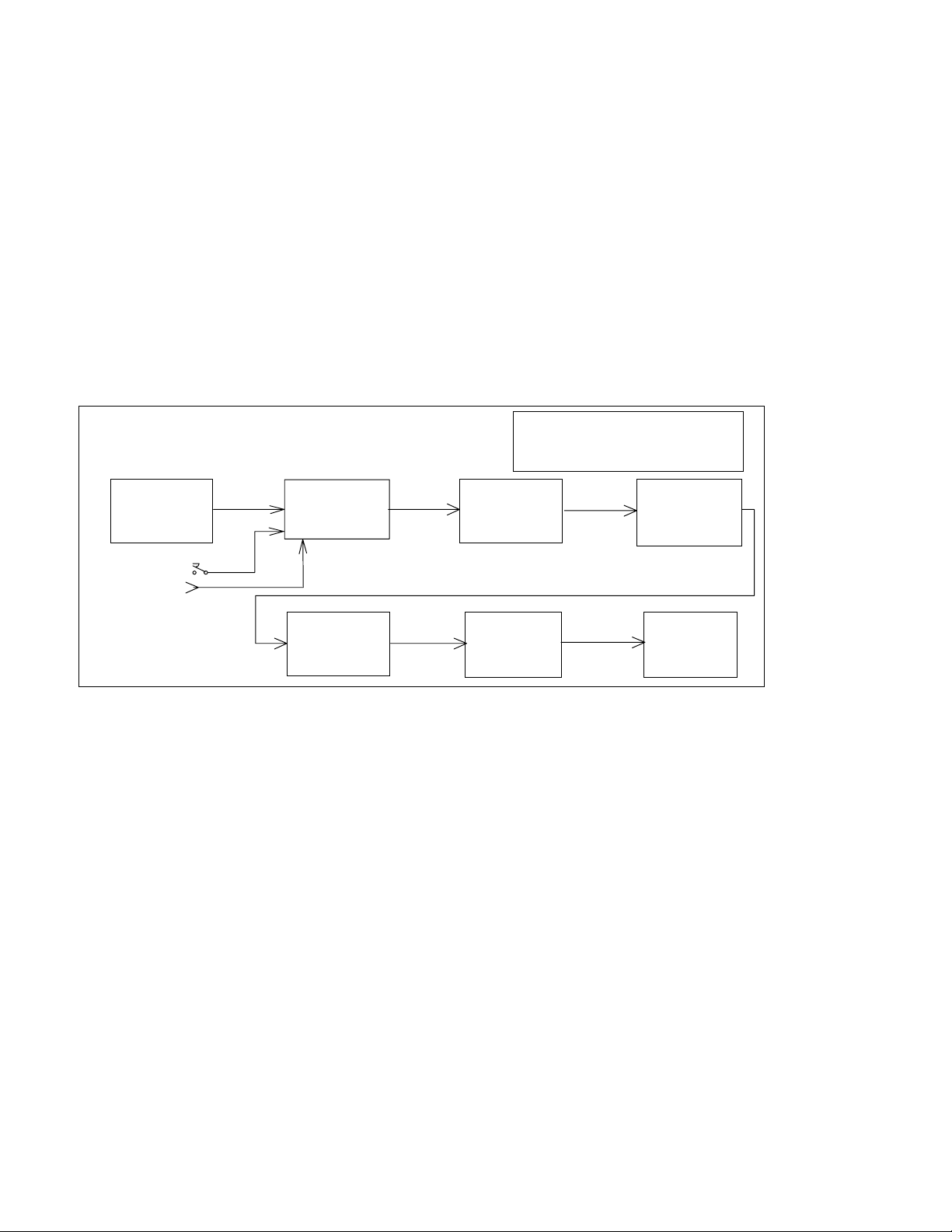
Transmitter Output Power
Test description: One of the first things an amateur wants to know about a transmitter or transceiver is its RF output power.
The ARRL Lab measures the CW output power for every band on which a transmitter can operate. The equipment is also
tested on one or more bands for any other mode of operation for which the transmitter is capable. Another purpose of the
Transmitter Output-Power Test is to measure the dc current consumption at the manufacturer's specified dc-supply voltage, if
applicable.
Many transmitters are de-rated from maximum output power on full-carrier AM and FM modes. In most cases, a 100-watt
CW/SSB transmitter may be rated at 25 watts carrier power on AM. The radio may actually deliver 100 watts PEP in AM or
FM but is not specified to deliver that power level for any period of time.
In almost all cases, the linearity of a transmitter decreases as output power increases. A transmitter rated at 100 watts PEP on
single sideband may actually be able to deliver more power, but as the power is increased beyond the rated RF output power,
adjacent channel splatter (IMD) usually increases dramatically.
Key Test Conditions:
Termination: 50 ohms resistive, or as specified by the manufacturer.
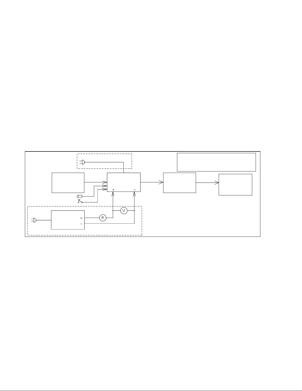
Block Diagram:
CAUTION!: Power must only be applied to the
attenuator input! Do not reverse input and output
terminals of the Bird 8329.
RF W
B
ATTMET ER
4381
IRD
100 W
T
YPICAL
ATTS
RF Power
Attenuator &
Dummy Load
Bird 8329
TWO-T
A
ENERATOR
G
WITCH
PTT S
ELEGRAPH KEY
T
UDIO
ONE
AC ONLY
T
DUT
RANSMITTER
100 W
T
YPICAL
ATTS
OWER
P
UPPLY
S
DC ONLY
ARRL Laboratory Expanded Test-Result Report Model: ICOM IC-746 Pro Serial: 01484
Copyright 2002, American Radio Relay League, Inc. All Rights Reserved.
Page 4
Transmitter Output Power Results
NOTE!: If comparing this table against the table from the IC-746 (Sept 98 QST), please be sure you
have a recent copy of the expanded report for the IC-746, as the original report contained incorrect data
for the high power output.
Frequency
Band
1.8 MHz CW See note 1 2.0 W “100” 103.4 W 1, 2
3.5 MHz CW – 2.2 – 107.7
3.5 MHz AM – 1.0 – 39.1 W carrier
7.0 MHz CW – 2.2 – 109.8
10.1 MHz CW – 2.3 – 110.6
14 MHz CW – 2.3 – 110.7
14 MHz USB – 2.2 – 108.0
18 MHz CW – 2.3 – 110.4
21 MHz CW – 2.2 – 107.0
24 MHz CW – 2.2 – 109.9
28 MHz CW – 2.2 – 109.3
28 MHz FM – 2.3 – 110.1
50 MHz CW – 1.8 – 103.3
50 MHz FM – 2.3 – 105.0
50 MHz AM – 1.2 – 38.6 W carrier
50 MHz SSB – 2.1 – 103.4
144 MHz CW – 2.4 – 97.4
144 MHz FM – 2.9 – 98.7
144 MHz AM – 1.3 – 39.5 W carrier
144 MHz SSB – 2.6 – 97.1
Notes:
1. Unit's power meter consists of LED segments; minimum power showed 0 segments lit.
2. The unit showed LED segments reaching a fixed display label reading 100 at full power.
Mode Unit
Minimum
Power (W)
Measured
Minimum
Power (W)
Unit
Maximum
Power (W)
Measured
Maximum
Power (W)
Notes
Current Consumption
(DC-powered units only)
Test Description: Current consumption can be important to the success of mobile and portable operation. The ARRL Lab
tests the current consumption of all equipment that can be operated from a battery or 12-14 vdc source. The equipment is
tested in transmit at maximum output power. On receive, it is tested at maximum volume, with no input signal, using the
receiver's broadband noise.
Current Consumption:
Voltage Transmit
Current
13.8 V 19.8 A 110.7 W 1.9 A ON
ARRL Laboratory Expanded Test-Result Report Model: ICOM IC-746 Pro Serial: 01484
Output Power Receive Current Lights? Notes
Copyright 2002, American Radio Relay League, Inc. All Rights Reserved.
Page 5
Transmit Frequency Range
Test Description: Many transmitters can transmit outside the amateur bands, either intentionally, to accommodate MARS
operation, for example, or unintentionally as the result of the design and internal software. The ARRL Lab tests the transmit
frequency range inside the screen room. Most modern synthesized transmitters are capable of operation outside the ham bands,
but spectral purity is not always legal outside the bands, so caution must be used. In addition, most other radio services require
that transmitting equipment be type accepted for that service. Amateur equipment is not legal for use on other than amateur
and MARS frequencies.
Test Results:
Frequency Low-Frequency Limit High-Frequency Limit Notes
160 M 1.800 000 MHz 1.999 999 MHz
80 M 3.500 000 MHz 3.999 999 MHz
40 M 7.000 000 MHz 7.300 000 MHz
30 M 10.100 000 MHz 10.150 000 MHz
20 M 14.000 000 MHz 14.350 000 MHz
17 M 18.068 000 MHz 18.168 000 MHz
15 M 21.000 000 MHz 21.450 000 MHz
12 M 24.890 000 MHz 24.990 000 MHz
10 M 28.000 000 MHz 29.700 000 MHz
6 M 50.000 000 MHz 54.000 000 MHz
2 M 144.000 000 MHz 148.000 000 MHz
CW Transmit Frequency Accuracy
Test Description: Most modern amateur equipment is surprisingly accurate in frequency. It is not uncommon to find
equipment operating within a few Hz of the frequency indicated on the frequency display. However, some units, notably
"analog" units, not using a phase-lock loop in the VFO design, can be off by a considerable amount. Frequency is also
measured at minimum output power, low supply voltage (12 volt units only) and over the operating temperature range
(mobile and portable units only). Non-portable equipment is not tested in the temperature chamber.
Test Results:
Unit Display
Frequency
14.000 000 MHz 13.8 V 25 C 13.999 995 MHz
50.000 000 MHz 13.8 V 25 C 49.999 980 MHz
144.000 000 MHz 13.8 V 25 C 143.999 948 MHz 1
Notes:
1. Measured frequency at low power output was 7 Hz lower on 2M.
Supply
Voltage
Temperature Measured Frequency
Full Output Power
Notes
ARRL Laboratory Expanded Test-Result Report Model: ICOM IC-746 Pro Serial: 01484
Copyright 2002, American Radio Relay League, Inc. All Rights Reserved.
Page 6

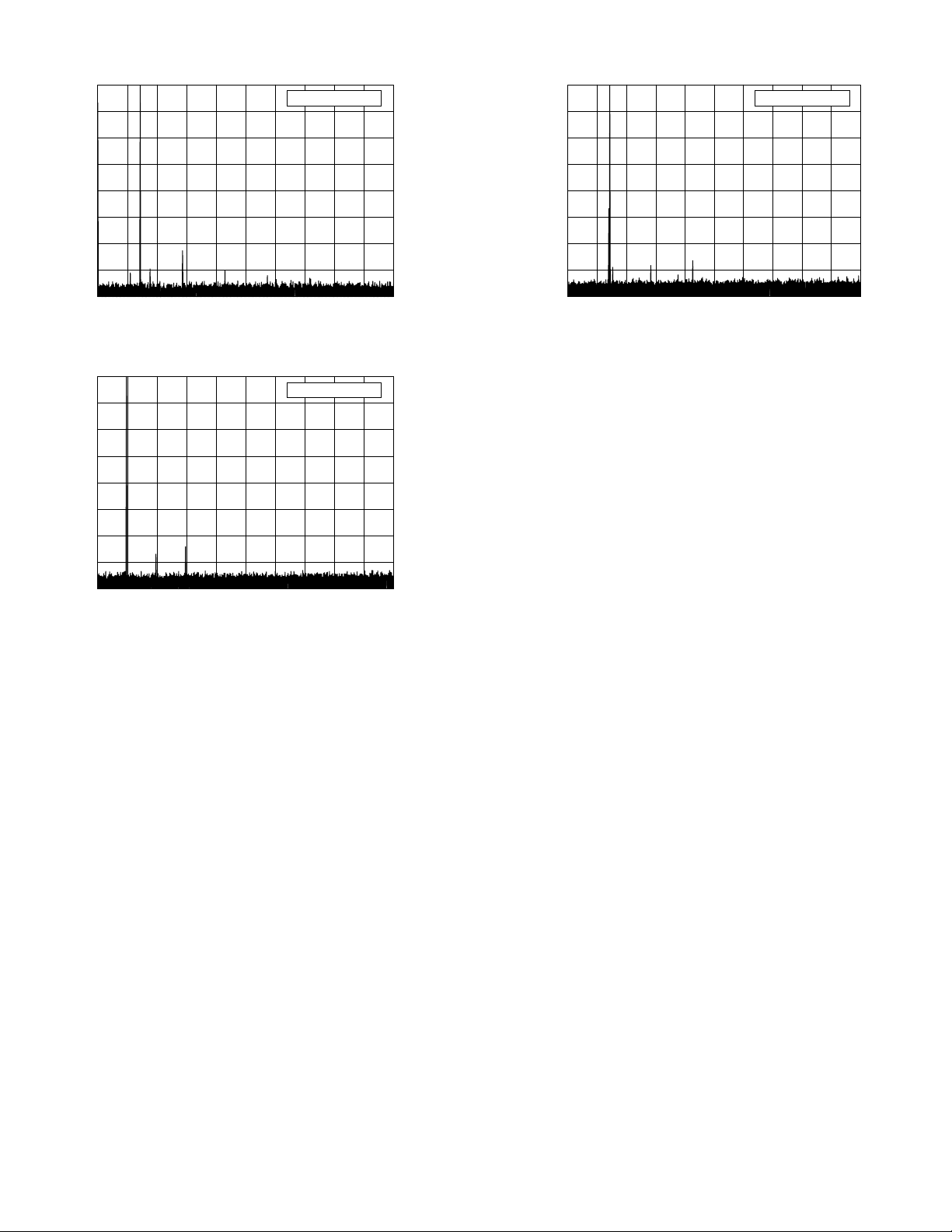
Spectral Purity
Test Description: All transmitters emit some signals outside their assigned frequency or frequency range. These signals are
known as spurious emissions or "spurs." Part 97 of the FCC rules and regulations specify the amount of spurious emissions
that can be emitted by a transmitter operating in the Amateur Radio Service. The ARRL Laboratory uses a spectrum analyzer
to measure the spurious emission on each band on which a transmitter can operate. The transmitter is tested across the band
and the worst-case spectral purity on each band is saved to a file on disk. Spectral purity is reported in dBc, meaning dB
relative to the transmitted carrier.
The graphs and tables indicate the relative level of any spurious emissions from the transmitter. The lower that level, the better
the transmitter is. So a transmitter whose spurious emissions are –60 dBc is spectrally cleaner than is one whose spurious
emissions are –30 dBc.
Key Test Conditions:
Unit is operated at nominal supply voltage and temperature.
Output power is adjusted to full power on each amateur band.
A second measurement is taken at minimum power to ensure that the spectral output is still legal at low power.
The resolution bandwidth of the spectrum analyzer is 10 kHz on HF, 100 kHz on VHF, 1 MHz on UHF.
Block Diagram:
CAUTION!: Power must only be applied to
the attenuator input! Do not reverse input
and output terminals of the Bird 8329.
G
ELEGRAPH KEY
T
OWER SOURCE
P
TWO-T
UDIO
A
ENERATOR
ONE
DUT
RANSMITTER
T
10 dB S
TTENUATOR
A
HP 355D
TEP
100 W
T
YPICAL
ATTS
RF W
ATTMET ER
B
4381
IRD
1 dB S
TTENUATOR
A
HP 3555C
TEP
100 W
T
YPICAL
DO NOT
EXCEED
0 dBm
ATTS
RF Power
Attenuator &
Dummy Load
Bird 8329
PECTRUM
S
NALYZER
A
HP 8563E
ARRL Laboratory Expanded Test-Result Report Model: ICOM IC-746 Pro Serial: 01484
Copyright 2002, American Radio Relay League, Inc. All Rights Reserved.
Page 7

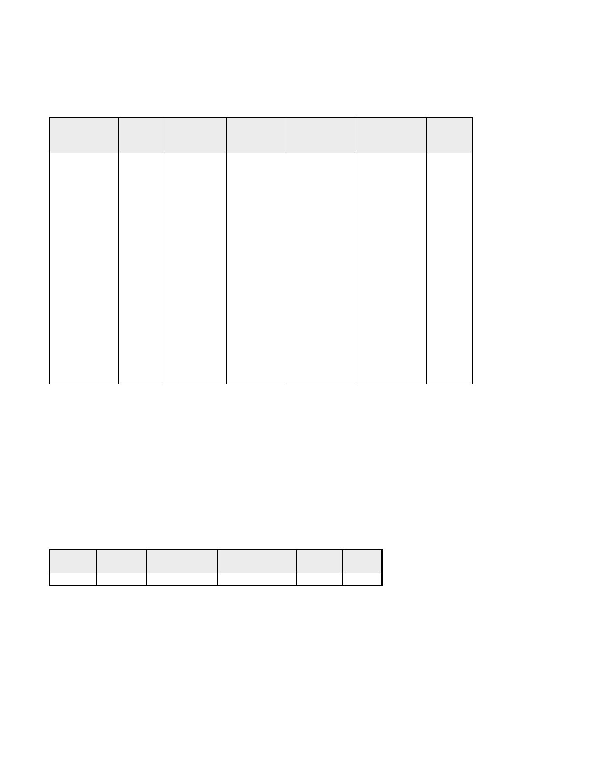
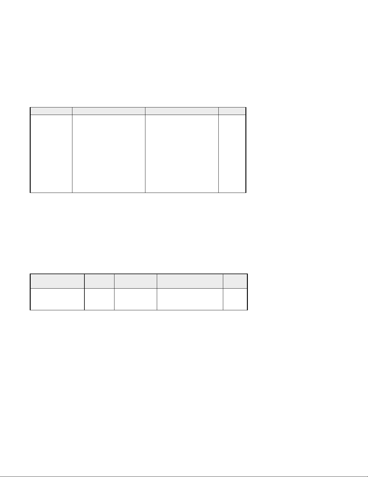
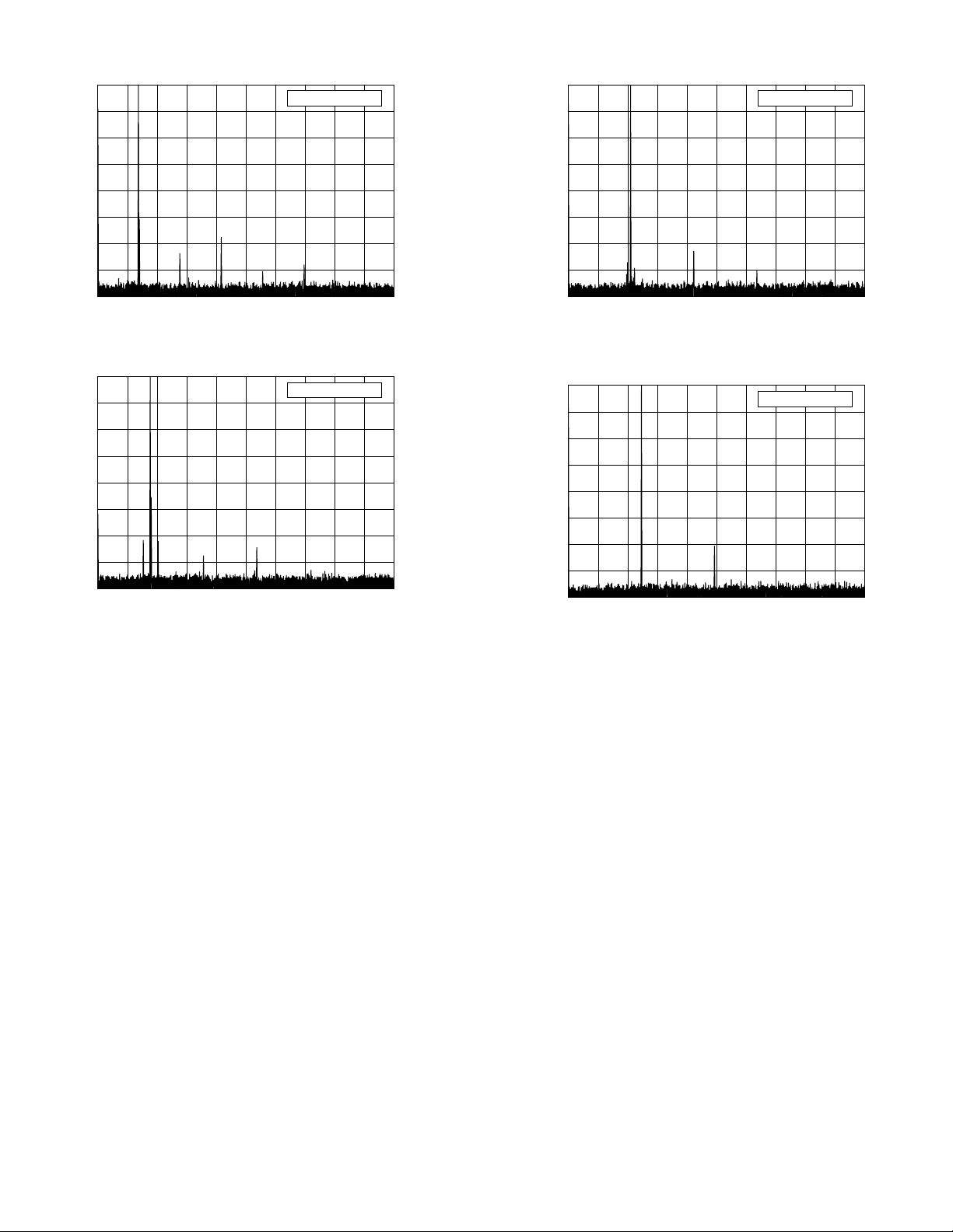
Spectral-Purity Graphs
I
1
I
0
–
–
–
–
–
–
–
–
I
3
I
0
–
–
–
–
–
–
–
–
I
7
I
0
–
–
–
–
–
–
–
–
I
1
I
100
–
–
–
–
–
–
–
–
0
Reference Level: 0 dBc
10
0
Reference Level: 0 dBc
10
20
30
40
50
60
70
80
0 5 10 15 20 25 30 35 40 45 5
COM IC-746 Pro, s/n 01484
.8 MHz Band, Spectral Purity, 100 W
:\PRODREV\TESTS\IC746PRO\746PRSLO.TXT
Frequency (MHz)
0
10
20
30
40
50
60
70
Reference Level: 0 dBc
20
30
40
50
60
70
80
0 5 10 15 20 25 30 35 40 45 5
COM IC-746 Pro, s/n 01484
.0 MHz Band, Spectral Purity, 100 W
:\PRODREV\TESTS\IC746PRO\746PRS40.TXT
Frequency (MHz)
0
10
20
30
40
50
60
70
Reference Level: 0 dBc
80
0 5 10 15 20 25 30 35 40 45 5
COM IC-746 Pro, s/n 01484
.5 MHz Band, Spectral Purity, 100 W
:\PRODREV\TESTS\IC746PRO\746PRS80.TXT
Frequency (MHz)
ARRL Laboratory Expanded Test-Result Report Model: ICOM IC-746 Pro Serial: 01484
Copyright 2002, American Radio Relay League, Inc. All Rights Reserved.
Page 8
80
0 10 20 30 40 50 60 70 80 90
COM IC-746 Pro, s/n 01484
0.1 MHz Band, Spectral Purity, 100 W
:\PRODREV\TESTS\IC746PRO\746PRS30.TXT
Frequency (MHz)
I
1
I
100
–
–
–
–
–
–
–
–
0
I
1
I
100
–
–
–
–
–
–
–
–
I
2
I
100
–
–
–
–
–
–
–
–
I
2
I
100
–
–
–
–
–
–
–
–
10
Reference Level: 0 dBc
20
30
40
50
60
70
80
0 10 20 30 40 50 60 70 80 90
COM IC-746 Pro, s/n 01484
4.0 MHz Band, Spectral Purity, 100 W
:\PRODREV\TESTS\IC746PRO\746PRS20.TXT
Frequency (MHz)
0
10
20
30
40
50
60
70
80
0 10 20 30 40 50 60 70 80 90
COM IC-746 Pro, s/n 01484
8.1 MHz Band, Spectral Purity, 100 W
:\PRODREV\TESTS\IC746PRO\746PRS17.TXT
Frequency (MHz)
Reference Level: 0 dBc
0
10
Reference Level: 0 dBc
20
30
40
50
60
70
80
0 10 20 30 40 50 60 70 80 90
COM IC-746 Pro, s/n 01484
1.0 MHz Band, Spectral Purity, 100 W
:\PRODREV\TESTS\IC746PRO\746PRS15.TXT
Frequency (MHz)
0
10
20
30
40
50
60
70
80
0 10 20 30 40 50 60 70 80 90
COM IC-746 Pro, s/n 01484
4.9 MHz Band, Spectral Purity, 100 W
:\PRODREV\TESTS\IC746PRO\746PRS12.TXT
Frequency (MHz)
Reference Level: 0 dBc
ARRL Laboratory Expanded Test-Result Report Model: ICOM IC-746 Pro Serial: 01484
Copyright 2002, American Radio Relay League, Inc. All Rights Reserved.
Page 9
I
2
I
200
–
–
–
–
–
–
–
–
0
I
5
I
500
–
–
–
–
–
–
–
–
I
1
I
0
–
–
–
–
–
–
–
–
10
Reference Level: 0 dBc
20
30
40
50
60
70
80
0 20 40 60 80 100 120 140 160 180
COM IC-746 Pro, s/n 01484
8.0 MHz Band, Spectral Purity, 100 W
:\PRODREV\TESTS\IC746PRO\746PRS10.TXT
Frequency (MHz)
0
10
20
30
40
50
60
Reference Level: 0 dBc
0
10
Reference Level: 0 dBc
20
30
40
50
60
70
80
0 100 200 300 400 500 600 700 800 900 100
COM IC-746 Pro, s/n 01484
44.0 MHz Band, Spectral Purity, 100 W
:\PRODREV\TESTS\IC746PRO\746PRS2M.TXT
Frequency (MHz)
70
80
0 50 100 150 200 250 300 350 400 450
COM IC-746 Pro, s/n 01484
0.0 MHz Band, Spectral Purity, 100 W
:\PRODREV\TESTS\IC746PRO\746PRS6M.TXT
Frequency (MHz)
ARRL Laboratory Expanded Test-Result Report Model: ICOM IC-746 Pro Serial: 01484
Copyright 2002, American Radio Relay League, Inc. All Rights Reserved.
Page 10
Transmit Two-Tone IMD
Test Description: Investigating the sidebands from a modulated transmitter requires a narrow-band spectrum analysis. In this
test, a two-tone signal is used to modulate the transmitter. The spectral display shows the test tones plus some of the IMD
products produced by the SSB transmitter. In the ARRL Lab, frequencies of 700 and 1900 Hz is used to modulate the
transmitter. These frequencies were selected to be within the audio passband of the typical transmitter, resulting in a
meaningful display of transmitter IMD. The intermodulation products appear on the spectral plot above and below the two
tones. The lower the products, the better the transmitter. In general, it is the products that are farthest removed from the two
tones (typically > 3 kHz away) that cause the most problems. These can cause splatter up and down the band from strong
signals.
Key Test Conditions:
Transmitter operated at rated output power. Audio tones and drive level adjusted for best performance. Both audio tones
adjusted for equal RF output. Level to spectrum analyzer, –10 dBm maximum. Resolution bandwidth, 10 Hz
Block Diagram:
CAUTION!: Power must only be applied to
the attenuator input! Do not reverse input
and output terminals of the Bird 8329.
G
ELEGRAPH KEY
T
OWER SOURCE
P
TWO-T
UDIO
A
ENERATOR
ONE
DUT
RANSMITTER
T
10 dB S
TTENUATOR
A
HP 355D
TEP
100 W
T
YPICAL
ATTS
RF W
ATTMET ER
B
4381
IRD
1 dB S
TTENUATOR
A
HP 3555C
TEP
100 W
T
YPICAL
DO NOT
EXCEED
0 dBm
ATTS
RF Power
Attenuator &
Dummy Load
Bird 8329
PECTRUM
S
NALYZER
A
HP 8563E
ARRL Laboratory Expanded Test-Result Report Model: ICOM IC-746 Pro Serial: 01484
Copyright 2002, American Radio Relay League, Inc. All Rights Reserved.
Page 11
 Loading...