

Page 1

INSTR UCTION MANUAL
VHF/HF ALL MODE TRANSCEIVER
i746
This device complies with Part 15 of the FCC rules. Operation is subject to the following two conditions: (1) This device may not cause
harmful interference, and (2) this device must accept any interference
received, including interference that may cause undesired operation.
Page 2
The IC-746’s which display the “CE” symbol, comply
with the essential requirements of the 89/336/EEC directive for Electromagnetic Compatibility. This compliance is based on conformity with the ETSI specification
prETS300 684 (EMC product standard for Commercially Available Amateur Radio Equipment).
ii
IMPORTANT
WORD DEFINITION
RWARNING
Personal injury, fire hazard or electric
shock may occur.
CAUTION
Equipment damage may occur.
NOTE
If disregarded, inconvenience only. No risk
of personal injury, fire or electric shock.
READ THIS INSTRUCTION MANUAL CAREFULLY
before attempting to operate the transceiver.
SAVE THIS INSTRUCTION MANUAL—This manual
contains important safety and operating instructions for
the IC-746.
PRECAUTIONS
RWARNING! HIGH VOLTAGE! NEVER attach an
antenna or internal antenna connector during transmission.This may result in an electric shock or burn.
RNEVER apply AC to the [DC13.8V] socket on the
transceiver rear panel.This could cause a fire or ruin
the transceiver.
RNEVER apply more than 16 V DC, such as a 24 V
battery , to the [DC13.8V] soc ket on the transceiver rear
panel.This could cause a fire or ruin the transceiver.
RNEVER let metal, wire or other objects touch any in-
ternal part or connectors on the rear panel of the transceiver. This may result in an electric shock.
NEVER allow children to play with equipment containing a radio transmitter.
NEVER expose the transceiver to rain, snow or any liquids.
AVOID using or placing the transceiver in areas with
temperatures below –10°C (+14°F) or above +60°C
(+140°F). Be aware that temperatures on a vehicle’s
dashboard can exceed 80°C (+176°F), resulting in permanent damage to the transceiver if left there for extended periods.
AVOID placing the transceiver in excessively dusty environments or in direct sunlight.
AVOID placing the transceiver against walls or putting
anything on top of the transceiver. This will obstr uct
heat dissipation.
During mobile operation, DO NOT operate the transceiver without running the vehicle’s engine. When
transceiver power is ON and your vehicle’s engine is
OFF, the vehicle’s battery will soon become exhausted.
Make sure the transceiver power is OFF before starting the vehicle.This will avoid possible damage to the
transceiver by ignition voltage spikes.
During maritime mobile operation, keep the transceiver
and microphone as far away as possible from the magnetic navigation compass to prev ent erroneous indications.
BE CAREFUL! The heatsink will become hot when operating the transceiver continuously for long periods.
BE CAREFUL! If a linear amplifier is connected, set
the transceiver’s RF output power to less than the linear amplifier’s maximum input level, otherwise, the linear amplifier will be damaged.
Use Icom microphones only (supplied or optional).
Other manufacturer’s microphones have different pin
assignments and connection to the IC-746 may damage the transceiver.
EXPLICIT DEFINITIONS
The explicit definitions described below apply to this instruction manual.
BUILT-IN DSP
The IC-746’s DSP digitally transposes receive audio
components in all modes of operation to produce desired AF frequency characteristics at the IF stage of
the transceiver. DSP provides the following functions:
➩ Noise reduction—reduces various types of noise
and enhances receive signal components only.
➩
Automatic notch filter—automatically reduces single
beat interference and protects the receive v oice signals.
➩ Selectable APF—a total of 3 passband widths are
selectable (80/160/320 Hz), for super-narrow filter
APF functions in CW mode. The APF center frequency is adjustable.
DSP
Page 3

iii
TABLE OF CONTENTS
IMPORTANT . . . . . . . . . . . . . . . . . . . . . . . . . . . . . . ii
PRECAUTIONS . . . . . . . . . . . . . . . . . . . . . . . . . . . . ii
EXPLICIT DEFINITIONS . . . . . . . . . . . . . . . . . . . . . ii
BUILT-IN DSP . . . . . . . . . . . . . . . . . . . . . . . . . . . . . ii
TABLE OF CONTENTS . . . . . . . . . . . . . . . . . . . . . iii
1 PANEL DESCRIPTION . . . . . . . . . . . . . . . . . . 2–7
1-1 Front panel . . . . . . . . . . . . . . . . . . . . . . . . . . . 2
1-2 Rear panel . . . . . . . . . . . . . . . . . . . . . . . . . . . 6
1-3 Function display . . . . . . . . . . . . . . . . . . . . . . . 7
2 MENU SELECTION . . . . . . . . . . . . . . . . . . . . . 8–9
2-1 Menu set 1 flow chart . . . . . . . . . . . . . . . . . . . 8
2-2 Menu set 2 flow chart . . . . . . . . . . . . . . . . . . . 9
3 BASIC OPERATION . . . . . . . . . . . . . . . . . . 10–17
3-1 Before operating . . . . . . . . . . . . . . . . . . . . . . 10
3-2 Squelch and receive (RF) sensitivity . . . . . . 12
3-3 Selecting VFO/memory mode . . . . . . . . . . . 13
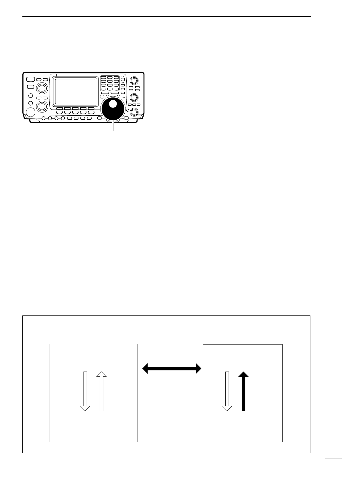
3-4 Toggling between VFO A/B and transferring
contents . . . . . . . . . . . . . . . . . . . . . . . . . . . . 13
3-5 Setting a band and frequency . . . . . . . . . . . 14
3-6 Selecting an operating mode . . . . . . . . . . . . 17
4 USING DIFFERENT OPERATING MODES . 18–36
4-1 Operating SSB . . . . . . . . . . . . . . . . . . . . . . . 18
4-2 Operating CW . . . . . . . . . . . . . . . . . . . . . . . . 20
4-3 Operating RTTY (FSK) . . . . . . . . . . . . . . . . . 28
4-4 Operating AM . . . . . . . . . . . . . . . . . . . . . . . . 30
4-5 Operating FM . . . . . . . . . . . . . . . . . . . . . . . . 32
4-6 Repeater operation . . . . . . . . . . . . . . . . . . . 34
4-7 Packet operation . . . . . . . . . . . . . . . . . . . . . . 36
5 FUNCTIONS FOR RECEIVE . . . . . . . . . . . . 37–42
5-1 Simple band scope . . . . . . . . . . . . . . . . . . . . 37
5-2 Preamp and attenuator . . . . . . . . . . . . . . . . 38
5-3 RIT function . . . . . . . . . . . . . . . . . . . . . . . . . 38
5-4 AGC function . . . . . . . . . . . . . . . . . . . . . . . . 39
5-5 1/4 function . . . . . . . . . . . . . . . . . . . . . . . . . . 39
5-6 NB function . . . . . . . . . . . . . . . . . . . . . . . . . . 39
5-7 Noise reduction . . . . . . . . . . . . . . . . . . . . . . 40
5-8 Auto notch (ANF) function . . . . . . . . . . . . . . 40
5-9 Dial lock function . . . . . . . . . . . . . . . . . . . . . 40
5-10 Twin PBT . . . . . . . . . . . . . . . . . . . . . . . . . . 41
5-11 Selecting IF filters . . . . . . . . . . . . . . . . . . . . 42
6 FUNCTIONS FOR TRANSMIT . . . . . . . . . . . 43–48
6-1 VOX function . . . . . . . . . . . . . . . . . . . . . . . . . 43
6-2 Break-in function . . . . . . . . . . . . . . . . . . . . . 44
6-3 :TX function . . . . . . . . . . . . . . . . . . . . . . . . 45
6-4 Monitor function . . . . . . . . . . . . . . . . . . . . . . 45
6-5 Speech compressor . . . . . . . . . . . . . . . . . . . 46
6-6 Split frequency operation . . . . . . . . . . . . . . . 47
6-7 Quick split function . . . . . . . . . . . . . . . . . . . . 48
7 MEMORY CHANNELS . . . . . . . . . . . . . . . . 49–54
7-1 General . . . . . . . . . . . . . . . . . . . . . . . . . . . . . 49
7-2 Memory channel selection . . . . . . . . . . . . . . 49
7-3 Transferring a memory to VFO . . . . . . . . . . . 50
7-4 Clearing a memory . . . . . . . . . . . . . . . . . . . . 50
7-5 Selecting the call channel . . . . . . . . . . . . . . 51
7-6 Programming a memory . . . . . . . . . . . . . . . . 51
7-7 Programming the call channel . . . . . . . . . . . 52
7-8 Programming scan edges . . . . . . . . . . . . . . 52
7-9 Assigning memory names . . . . . . . . . . . . . . 53
7-10 Memo pads . . . . . . . . . . . . . . . . . . . . . . . . 54
8 SCAN OPERATION . . . . . . . . . . . . . . . . . . . 55–58
8-1 Scan types . . . . . . . . . . . . . . . . . . . . . . . . . . 55
8-2 Programmed scan and
fine programmed scan . . . . . . . . . . . . . . . . . 56
8-3 Memory scan . . . . . . . . . . . . . . . . . . . . . . . . 57
8-4 Select memory scan . . . . . . . . . . . . . . . . . . . 57
8-5 :F scan and fine :F scan . . . . . . . . . . . . . . 58
9 INTERNAL ANTENNA TUNER . . . . . . . . . . . . . 59
9-1 Before operating . . . . . . . . . . . . . . . . . . . . . . 59
9-2 Tuner operation. . . . . . . . . . . . . . . . . . . . . . . 59
10 SET MODE . . . . . . . . . . . . . . . . . . . . . . . . . 60–64
10-1 Selecting set mode . . . . . . . . . . . . . . . . . . . 60
10-2 Set mode items . . . . . . . . . . . . . . . . . . . . . 60
11 ADJUSTMENTS . . . . . . . . . . . . . . . . . . . . . 65–66
11-1 Tuning dial brake . . . . . . . . . . . . . . . . . . . . 65
11-2 Frequency calibration . . . . . . . . . . . . . . . . . 65
11-3 Measuring SWR . . . . . . . . . . . . . . . . . . . . . 66
11-4 Adjusting the LCD . . . . . . . . . . . . . . . . . . . 66
12 SETUP AND CONNECTIONS . . . . . . . . . . 67–75
12-1 Front panel . . . . . . . . . . . . . . . . . . . . . . . . . 67
12-2 Rear panel . . . . . . . . . . . . . . . . . . . . . . . . . 68
12-3 Selecting a location . . . . . . . . . . . . . . . . . . 69
12-4 Power supply connections . . . . . . . . . . . . . 69
12-5 Grounding . . . . . . . . . . . . . . . . . . . . . . . . . 70
12-6 Antenna . . . . . . . . . . . . . . . . . . . . . . . . . . . 70
12-7 Data communications . . . . . . . . . . . . . . . . . 72
12-8 RTTY connections . . . . . . . . . . . . . . . . . . . 73
12-9 Remote jack . . . . . . . . . . . . . . . . . . . . . . . . 74
13 OPTIONAL INSTALLATIONS . . . . . . . . . . 76–80
13-1 Opening the transceiver’s case . . . . . . . . . 76
13-2 UT-102
VOICE SYNTHESIZER UNIT
. . . . . . . . . 77
13-3 CR-282
HIGH STABILITY CRYSTAL UNIT
. . . . . 77
13-4 Optional IF filters . . . . . . . . . . . . . . . . . . . . 78
13-5 Linear amplifier connections . . . . . . . . . . . 79
13-6 External antenna tuner connections . . . . . . 80
14 MAINTENANCE . . . . . . . . . . . . . . . . . . . . . 81–83
14-1 Fuse replacement . . . . . . . . . . . . . . . . . . . 81
14-2 Resetting the CPU . . . . . . . . . . . . . . . . . . . 81
14-3 Troubleshooting . . . . . . . . . . . . . . . . . . . . . 82
15 SPECIFICATIONS AND OPTIONS . . . . . . 84–85
15-1 Specifications . . . . . . . . . . . . . . . . . . . . . . . 84
15-2 Options . . . . . . . . . . . . . . . . . . . . . . . . . . . . 85
Page 4
2
1
PANEL DESCRIPTION
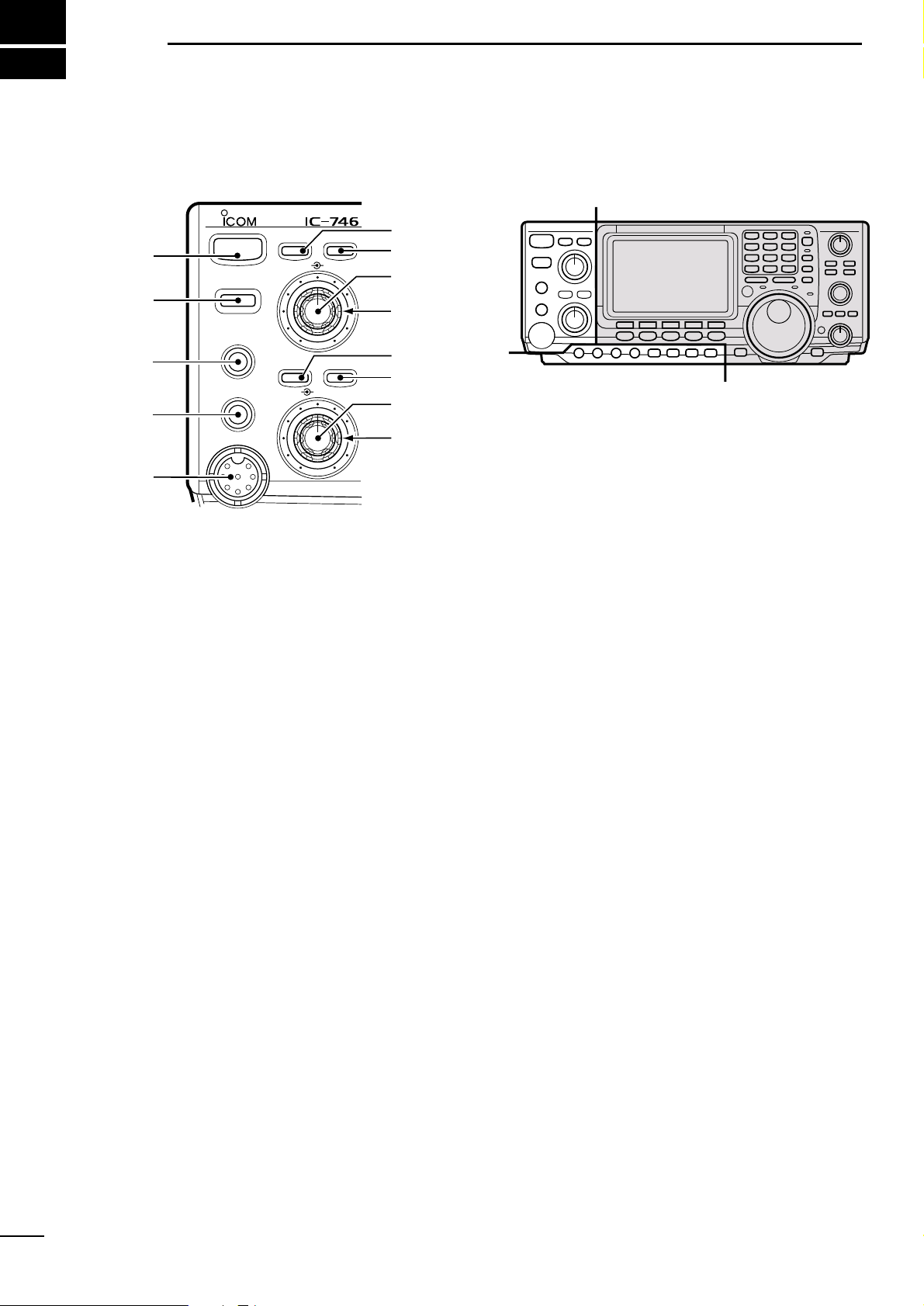
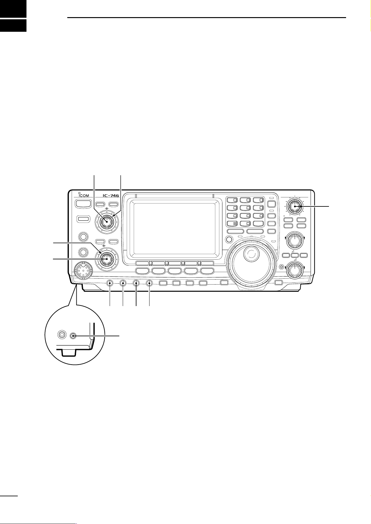
1-1 Front panel
q POWER SWITCH [POWER]
➥ Push momentarily to turn power ON. (p. 11)
• Turn the optional DC power supply ON in advance.
➥ Push and hold to turn power OFF.
w TRANSMIT SWITCH [TRANSMIT]
Toggles between transmit and receive.
• The [TX] indicator lights red while transmitting and the
[RX] indicator lights green when the squelch is open.
e HEADPHONE JACK [PHONES] (p.67)
Accepts headphones.
• When headphones are connected, the internal speaker
or connected external speaker does not function.
r ELECTRONIC KEYER JACK [ELEC-KEY] (p. 67)
Accepts a paddle to activate the internal electronic
keyer for CW operation.
• Selection between the internal electronic keyer, bug-key
and straight key operation can be made in keyer set
mode.
• A straight key jack is separately available on the rear
panel.
• Key polarity (dot and dash) can be reversed in keyer set
mode.
• 4-channel memor y keyer is available for your convenience.
t MICROPHONE CONNECTOR [MIC]
Accepts the supplied or optional microphone.
• See p.85 for appropriate microphones.
• See p.67 for microphone connector information.
y ANTENNA TUNER SWITCH [TUNER] (p. 59)
➥ Tur ns the antenna tuner ON and OFF (bypass)
when pushed momentarily.
➥ Starts to tune the antenna manually when
pushed for 2 sec.
• When the tuner cannot tune the antenna, the tuning
circuit is bypassed automatically after 20 sec.
u ANTENNA SELECTOR SWITCH [ANT] (p.71)
Toggles between the HF and 50 MHz antenna connectors.
i NOISE REDUCTION LEVEL CONTROL [NR]
(p.40)
Adjusts the noise reduction level when the noise reduction function is in use. Set for maximum readability.
o AUDIO PEAK FILTER CONTROL [APF] (p.20)
V aries the peak frequency of the audio peak filter to
pick out a CW signal from interference while the
APF function is ON.
!0 NOISE REDUCTION SWITCH [NR] (p. 40)
Toggles the noise reduction function ON and OFF.
Functions in SSB, CW and RTTY modes.
!1 AUDIO PEAK FILTER/AUTO NOTCH SWITCH
[APF/ANF]
➥ Toggles between the audio peak (p.20) and auto
notch (p. 40) functions.
• The audio peak filter functions in CW mode only; the
auto notch functions in SSB, FM and AM modes only.
• The APF or ANF indicator appear in the display depending on which function is selected.
➥ When the APF indicator appears, push this
switch for 1 sec., one or more times to select 320
Hz, 160 Hz or 80 Hz bandwidths.
• Use the [APF] control to vary the peak frequency.
!2 AF CONTROL [AF] (inner control; p. 12)
Varies the audio output level from the speaker.
PHONES
TRANSMIT
POWER
TUNER ANT
ELEC-KEY
MIC
NR APF/ANF
AF RF/SQL
NR APF
1
2
3
4
5
6
7
8
9
!1
!2
!3
!0
Å
Å
ı
Page 5
3
1
PANEL DESCRIPTION
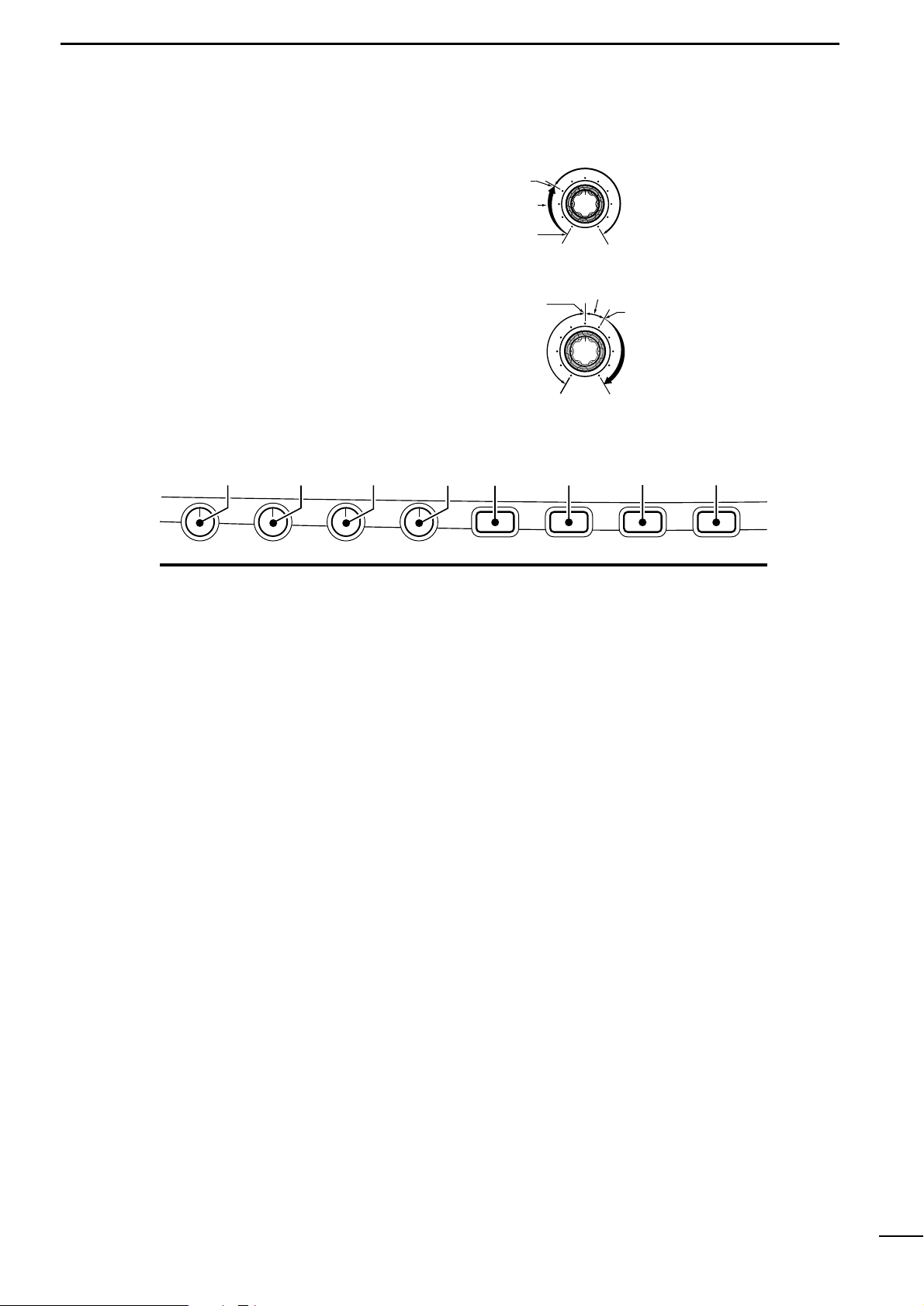
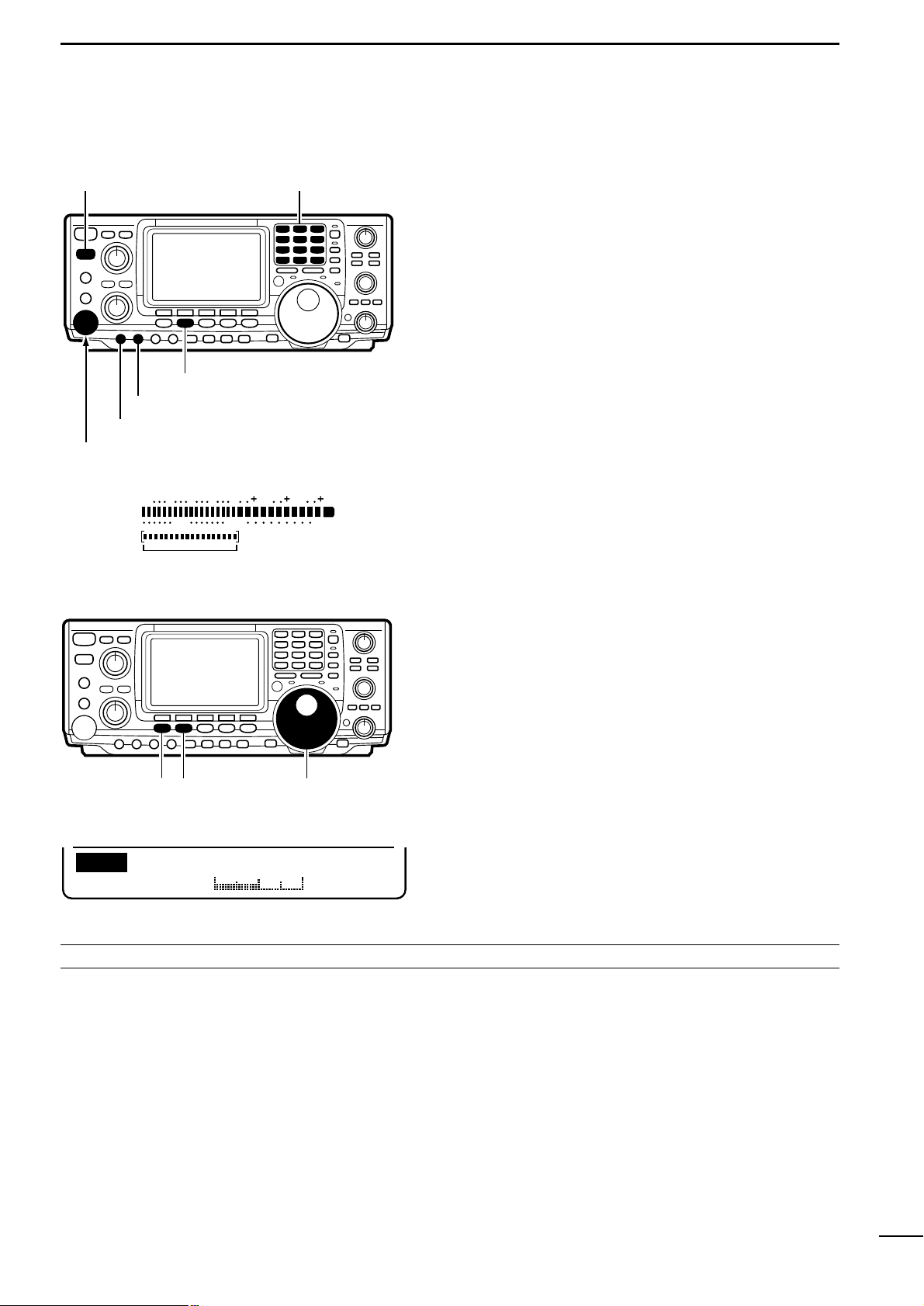
!3 RF GAIN/SQUELCH CONTROL [RF/SQL] (p.12)
Adjusts the RF gain and squelch threshold level.
The squelch removes noise output from the speak er
(closed condition) when no signal is received.
• The squelch is particularly effective for FM. It is also
available for other modes.
• The control can be set as the RF gain control only
(squelch is fixed open) or squelch control (RF gain is
fixed at maximum) in set mode.
!4 MIC GAIN CONTROL [MIC GAIN]
Adjusts the microphone input gain.
!5 RF POWER CONTROL [RF PWR] (p. 84)
Continuously varies the RF output power from minimum (2 W*) to maximum (100 W*).
*AM mode: 2–40 W, other modes: 5–100 W.
!6 CW PITCH CONTROL [CW PITCH] (p.20)
Shifts the received CW audio pitch and monitored
CW audio pitch without changing the operating frequency.
• The pitch can be changed from 300 to 900 Hz in approx.
3 Hz steps.
!7 ELECTRONIC CW KEYER SPEED CONTROL
[KEY SPEED] (p.22)
Adjusts the internal electronic CW keyer’s speed.
• 6 wpm to 60 wpm can be set.
!8 PREAMP/ATTENUATOR SWITCH [P.AMP/ATT]
(p.38)
➥ Push momentarily to toggle between preamp-1
and preamp-2.
➥ Push for 1 sec. to toggle the attenuator function
ON and OFF.
!9 NOISE BLANKER SWITCH [NB] (p. 39)
Toggles the noise blanker ON and OFF.The noise
blanker reduces pulse-type noise such as that generated by automobile ignition systems.This function
cannot be used for FM, or non pulse-type noise.
@0 VOX/BREAK-IN SWITCH [VOX/BK-IN]
➥ In SSB, AM and FM modes, push momentarily to
turn the VOX function ON; push for 1 sec. to turn
the VOX function OFF. (p. 43)
➥ In CW mode, push momentarily to select semi
break-in, full break-in or break-in OFF; push for 2
sec. to enter break-in set mode. (p. 44)
@1 MONITOR SWITCH [MONI] (p.45)
➥ Push to toggle the monitor function ON and OFF.
➥ Push for 2 sec. to enter and exit monitor set
mode.
Adjustable
range
Maximum
RF gain
Maximum
RF gain
sensitivity
Minimum
RF gain
sensitivity
• Setting squelch
• Setting RF gain
Squelch
threshold
Squelch
open
S-meter squelch
operating
range
S-meter squelch
threshold
Noise squelch
operating range
MIC GAIN RF PWR CW PITCH P.AMP/ATTKEY SPEED NB VOX/BK-IN MONITOR
!4 !5 !6 !7 !8 !9
@0
@1
ı
Page 6
4
1
PANEL DESCRIPTION
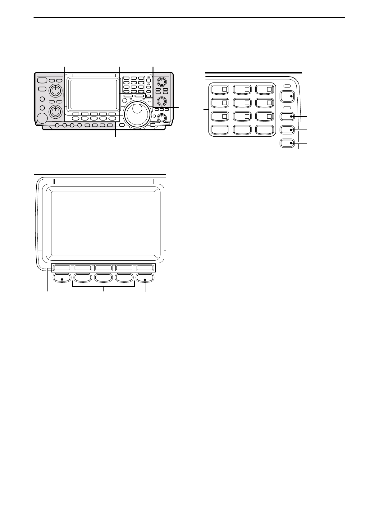
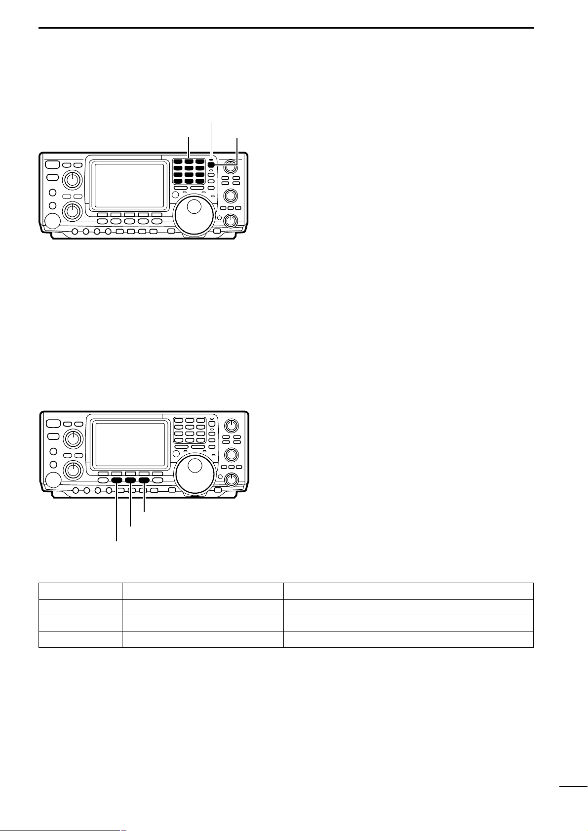
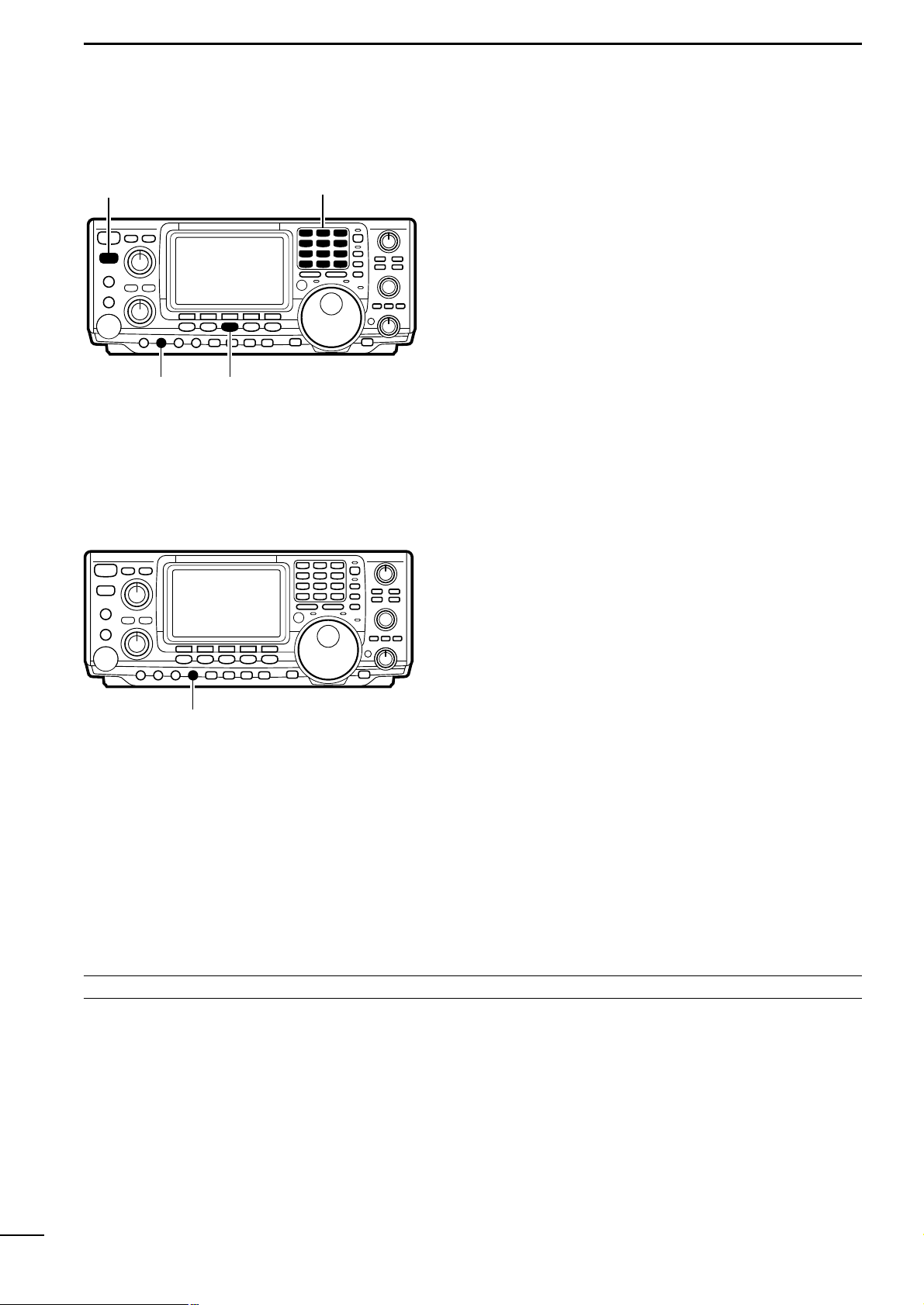
@2 MULTI-FUNCTION SWITCHES (p. 8)
➥ Push to select the functions indicated in the func-
tion display above these switches.
➥ Push to input a character for memory keyer pro-
gramming or memory name.
@3 MENU SWITCH [MENU] (p. 8)
Push to change the set of functions assigned to the
multi-function switches.
• Toggles between menu set 1 and menu set 2.
@4 MODE SWITCHES (p. 17)
Select an operating mode.
• Push [SSB] to toggle between LSB and USB.
• Push [CW/RTTY] to toggle between CW and RTTY.
• Push [CW/RTTY] for 1 sec. to toggle between CW and
CW-R or RTTY and RTTY-R.
@5 FILTER SWITCH (pgs. 42, 78)
➥ Push momentarily to toggle between normal and
narrow IF filters for the selected operating mode.
➥ Push for 1 sec. to enter normal or narrow IF filter
set mode.
Ç Î
´
TS
1.8
1
3.5
2
7
3
10
4
14
5
18
144ENT
6
21
7
•
24
8
28
9
GENE
50
0
A/B
SPLIT
F-INP
@7
@8
@9
#0
@6
Î
F1 F2 F3 F4 F5
MENU SSB
CW/RTTY
AM/FM FILTER
HF/VHF TRANSCEIVER
@2
Ç
@3
@4
@5
@6 KEYPAD (p. 14)
➥ Push a key to select an operating band.
• [GENE] selects the general coverage band.
➥ Push the same key 2 or 3 times to call up stacked
frequencies in the band.
• Icom’s band stacking register memorizes 3 frequencies (and modes) in each band.
@7 FREQUENCY INPUT SWITCH [F-INP] (p.17)
➥ Toggles keypad input between frequency and
band.
• The LED lights green to indicate the switch is set for
frequency input.
@8 SPLIT SWITCH [SPLIT] (p. 47)
Push to toggle the split function ON and OFF.
• The LED lights green to indicate split operation (between
VFO A and VFO B is selected).
@9 A/B SWITCH [A/B] (p. 13)
➥ Push to toggle between VFO A and VFO B.
➥ Push for 1 sec. to equalize the contents of VFO
A and VFO B.
#0 QUICK TUNING STEP SWITCH [TS] (p. 15)
➥ Turns the quick tuning step ON and OFF.
• While the quick tuning indicator is displayed, the frequency can be changed in programmed kHz steps.
• 1, 5, 9 and 10 kHz quick tuning steps are available.
➥ While the quick tuning step is OFF, turns the 1 Hz
step ON and OFF when pushed for 2 sec.
• 1 Hz indications appear in both readouts and the frequency can be changed in 1 Hz steps.
➥ While the quick tuning step is ON, enters the
quick tuning step mode when pushed for 2 sec.
Page 7

5
1
PANEL DESCRIPTION
#1 TUNING DIAL
Changes the displayed frequency, selects set mode
items, etc.
#2 TRANSMIT FREQUENCY CHECK SWITCH [XFC]
(pgs.34, 38, 45, 47)
Monitors the transmit frequency when pushed and
held when the split frequency function is ON.
• While pushing this switch, the transmit frequency can be
changed with the tuning dial, keypad or the memo pad.
• When the split lock function is turned ON, pushing [XFC]
cancels the dial lock function.
#3 MEMO PAD WRITE SWITCH [MP-W] (p.54)
Programs the selected readout frequency and operating mode into a memo pad.
• The 5 most recent entries remain in memo pads.
• The transmit frequency is programmed when pushed to-
gether with [XFC].
• The memo pad capacity can be expanded from 5 to 10
in set mode for your convenience.
#4 TRANSMIT INDICATOR [TX]
Lights red while transmitting.
#5 MEMO PAD READ SWITCH [MP-R] (p. 54)
Each push calls up a frequency and operating mode
in a memo pad. The (or 10) most recently programmed frequencies and operating modes can be
recalled, starting from the most recent.
• The memo pad capacity can be expanded from 5 to 10
in set mode for your convenience.
#6 RECEIVE INDICATOR [RX]
Lights green while receiving a signal or when the
squelch is open.
#7 LOCK INDICATOR [LOCK] (p. 40)
Lights when the dial lock function is activated.
#8 SPEECH SWITCH [SPEECH] (p. 77)
Announces the selected readout frequency when an
optional UT-102 is installed.
#9 LOCK SWITCH [LOCK] (p. 40)
Turns the dial lock function ON and OFF.
$0 RIT SWITCH [RIT] (p. 38)
➥ Turns the RIT function ON and OFF when
pushed.
• Use the [RIT/:TX] control to vary the RIT frequency .
➥ Adds the RIT shift frequency to the operating fre-
quency when pushed for 2 sec.
$1 :TX SWITCH [:TX] (p. 45)
➥ Turns the :TX function ON and OFF when
pushed.
• Use the [RIT/:TX] control to vary the :TX frequency.
➥ Adds the :TX shift frequency to the operating
frequency when pushed for 2 sec.
$2 CLEAR SWITCH [CLEAR] (pgs. 38, 45)
Clears the RIT/:TX shift frequency when pushed
for 2 sec.
$3 RIT/:TX CONTROL [RIT/:TX] (pgs. 38, 45)
Shifts the receive and/or transmit frequency without
changing the transmit and/or receive frequency
while the RIT and/or :TX functions are ON.
• Rotate the control clockwise to increase the frequency,
or rotate the control counterclockwise to decrease the
frequency.
• The shift frequency range is ±9.999 kHz in 1 Hz steps
(or ±9.99 kHz in 10 Hz steps).
$4 BRAKE ADJUSTMENT SCREW (p. 65)
Adjusts the tension of the tuning dial.
• Rotate clockwise to increase the tension; counterclockwise to decrease the tension.
LOCK
XFC
RIT/ TX
SPEECH LOCK
TX RX
MP-W MP-R
RIT
TX CLEAR
´
#1
#2 #3
#4
#5 #6 #7
#8
#9
$0
$1 $2
$3
$4
Page 8

6
1
PANEL DESCRIPTION
$5 PASSBAND TUNING CONTROLS [TWIN PBT]
(p.41)
Adjust the receiver’s “passband width” of the 455
kHz and 9 kHz IF filters for the inner and outer controls, respectively.
• Passband width and center frequency are displayed in
the function display.
• Set to the center positions when not in use.
• Variable r ange depends on the filter selection. ±1.29 kHz
in 15 Hz steps and ±258 Hz in 3 Hz steps are available.
$6 VFO/MEMORY SWITCH [V/M]
➥ Toggles the selected readout operating mode be-
tween VFO mode and memory mode when
pushed.
➥ Transfers the memory contents to VFO when
pushed for 2 sec.
$7 CALL CHANNEL SWITCH [CALL] (p. 51)
Brings up the call channel.
• When the call channel is displayed, push this switch to
exit call channel mode.
$8 MEMORY WRITE SWITCH [MW] (p. 51)
Stores the selected readout frequency and operating mode into the displayed memory channel when
pushed for 2 sec.
• This function is available in both VFO and memory
modes.
$9 MEMORY CLEAR SWITCH [M-CL] (p.50)
Clears the selected readout memory channel contents when pushed for 2 sec.in memory mode.
• This switch does not function in VFO mode.
%0 MEMORY CHANNEL CONTROL [M-CH] (p.49)
Selects a memory channel.
• Rotate clockwise to increase the memory channel; rotate counterclockwise to decrease the memory channel.
Ï
M-CH
V/M CALL
M VFO
TWIN PBT
MW M-CL
Ï
$5
$6 $7
$8 $9
%0
wq
[ANT1][ANT2]
[ANT144MHz]
[REMOTE]
[SP]
[KEY JACK] [ACC1/2] [SEND]
[ALC]
1-2 Rear panel
q CALIBRATION POT [CAL]
This is used for frequency calibration (p. 65).
• The transceiver has been adjusted and calibrated thoroughly at the factory. Under normal circumstances, the
frequency does not need to be recalibrated.
w COMPRESSION LEVEL CONTROL [COMP GAIN]
(p.46)
Adjusts the speech compression level in SSB.
☞ NOTE: Refer to “12-2 Rear panel”(p.68) for details
concerning other rear panel connectors, etc.
Page 9

7
1
PANEL DESCRIPTION
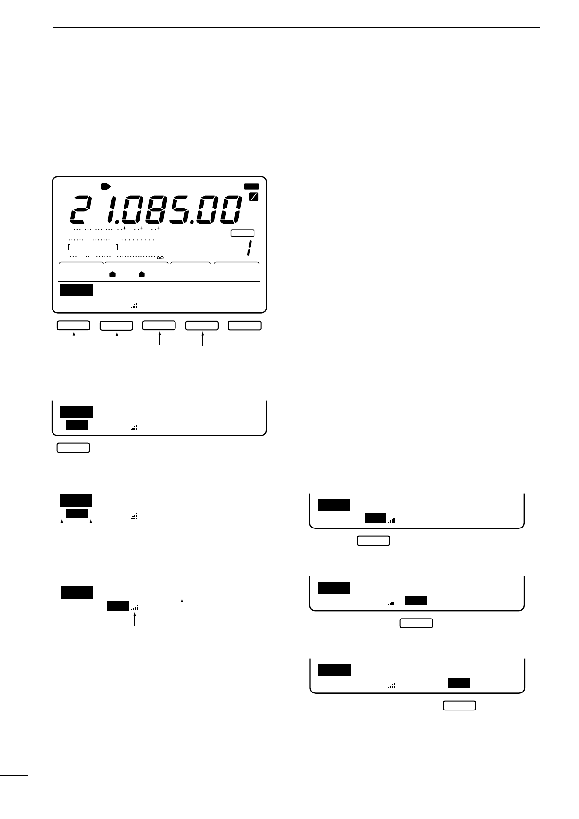
q ANTENNA TUNER INDICA TORS (pgs.59, 79)
➥ “TUNE” appears when the antenna tuner is ON;
“TUNE” appears and flashes dur ing manual tun-
ing.
➥ “EXT” appears when the optional AH-4 external
HF antenna tuner is connected to [ANT1].
w ANTENNA INDICATORS (p. 71)
Indicate which antenna connector is in use for
HF/50 MHz.
e MODE INDICATORS (p. 7)
Indicate the selected operating mode.
r NARROW FILTER INDICATOR (p.42)
Appears when the narrow IF filter is selected.
t
1
⁄4 TUNING DIAL SPEED INDICATOR (p. 39)
Appears when the tuning dial is set so that one revolution is equal to 1⁄4 of the normal revolution.
y FREQUENCY READOUT
Shows the operating frequency.
u MULTI-FUNCTION METER INDICATION
Displays S-meter reading during receive;“P
0,”“ALC”
and “SWR”meters can be selected for transmit.
i RIT/
:TX INDICATORS (pgs.38, 45)
Appear during RIT or :TX operation and indicate
the frequency offset.
o VFO/CALL/MEMORY INDICATORS
Indicate whether VFO A, VFO B, the call channel or
memory mode is selected.
!0 BLANK MEMORY INDICATOR (p.49)
Appears when the selected memory channel is
blank.
!1 SELECT MEMORY INDICATOR (p.57)
Appears when the selected memory channel is a
“select” memory channel.
BLANK
1
4
MW
APF
CH
MEMO
VFOB
VFOA
SEL
NR
ANFTSQLXFC
TUNE
ANT RTTY RAMWFM
NBMONICOMP
DUPSPLIT
RIT TX
OFFAGCATTAMP
P.BKVOX
SWR
ALC
Po
S
1
20 50
3
3211.5
579 20 40 60
IN
N
100%
EXT
NAR
CALL
21
F
1
2
F
S
LSB
USBCW
M1
AGCDUPCMPTCNSCP
BLANK
MW
APF
CH
MEMO
VFOB
VFOA
SEL
NR
ANFTSQLXFCNBMONICOMP
DUPSPLIT
RIT TX
OFFAGCATTAMP
P.BKVOX IN
N
CALL
F
1
2
F
S
1
23
4
5
6
7
8
9
!1
!0
!2
!3 !4
!5
!6
!7
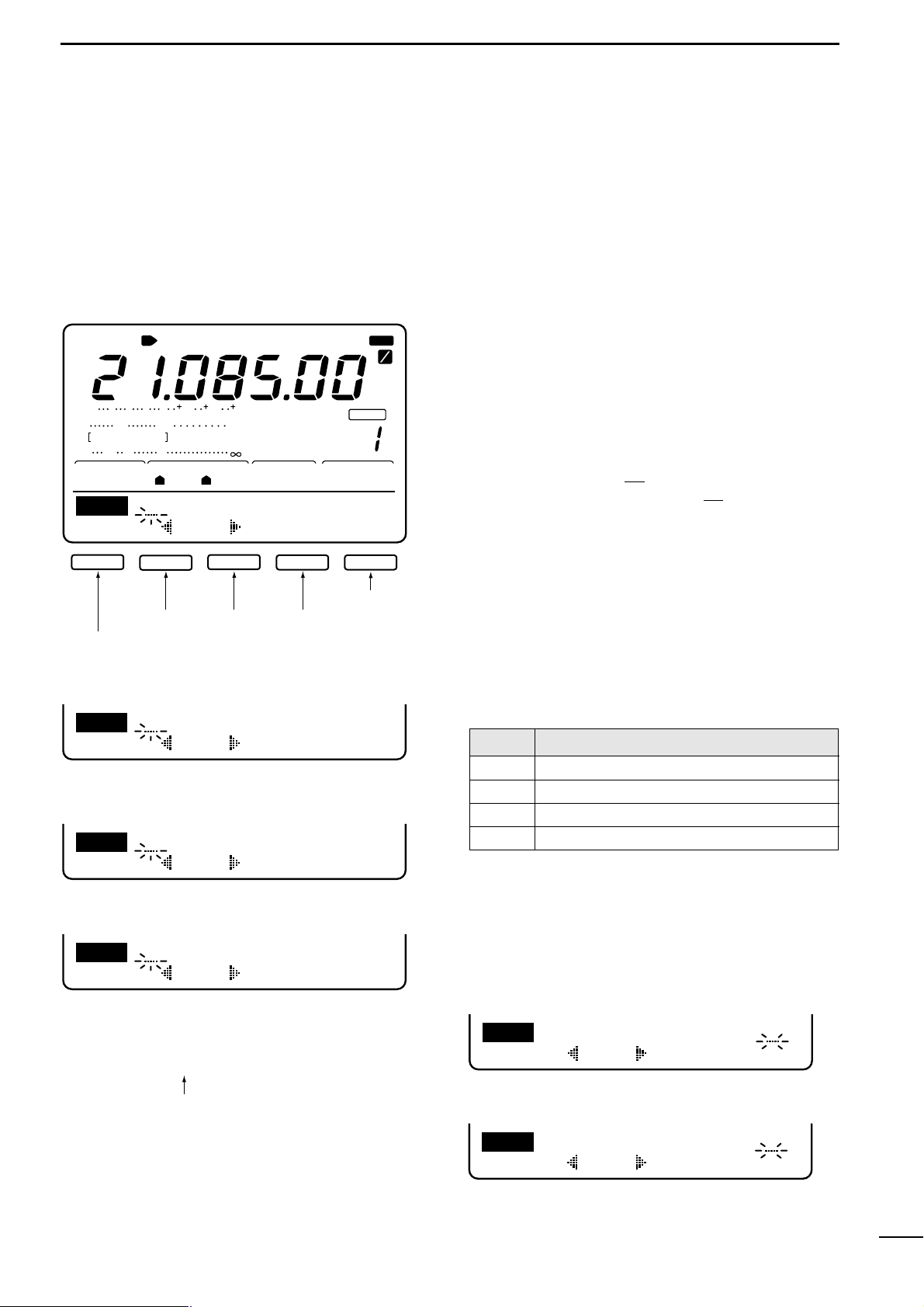
!2 MEMORY CHANNEL INDICATOR (p.49)
Shows the selected memory channel.
!3 TRANSMIT FUNCTION INDICATORS
Indicate functions selected for transmit.
!4 RECEIVE FUNCTION INDICATORS
Indicate functions selected for receive.
!5 SPLIT FUNCTION INDICATOR
Appears during split operation.
!6 DSP FUNCTION INDICATORS
Appear when DSP functions are selected.
!7 MULTI-FUNCTION SWITCH INDICATORS (p. 8)
Indicate the functions assigned to the multi-function
switches (F1–F5).
1-3 Function display
Page 10
8
2
MENU SELECTION
M1M2M3M4 -1
BLANK
CH
ANT
USB
AGCAMP
P.
SWR
ALC
Po
S
1
20 50
3
3211.5
579 20 40 60
100%
1
1
S
M1
AGCDUPCMPTCNSCP
F1
F2
F3 F4 F5
TCN
LH
0
SSBTXTone
SCP
STEP
0.5k
F1 F5
F1
F2
F3 F4 F5
M1
AGCDUP1/4KEYSCP
F2
F3 F4 F5
SNDEDT001SET
KEY
F1
F2
F3 F4 F5
001
SND
50%
SideToneLevel
SET
F1
F2
Normal
NumberStyle
001
F1
F2
F1
F2
F3 F4 F5
EDT
M1
DELSPC
CQTESTCQTEST
F5
F4
F3
F1
F2
F3 F4 F5
M1
AGCDUP1/4RTYSCP
2125
RTTYMark
RTY
F1
F2
F1
F2
F3 F4 F5
M1
AGCDUPTONTSQSCP
F1
F2
F3 F5
M1
AGCDUPCMPSCP
VFOA
SSB MODE
BAND SCOPE MENU
RTTY MODE
AM MODE
FM MODE
CW MODE
To band scope
menu
EDIT MENU
CONTEST NUMBER MENU
KEYER SET MODE
MEMORY KEYER MENU
SEND MENU
(p. 24)
(p. 23)
(p. 27)
(p. 26)
(p. 25)
(
p. 37
)
(p. 29)
(p. 19)
RTTY MENU
TONE CONTROL MENU
To band scope
menu
To band scope
menu
To band scope
menu
To band scope
menu
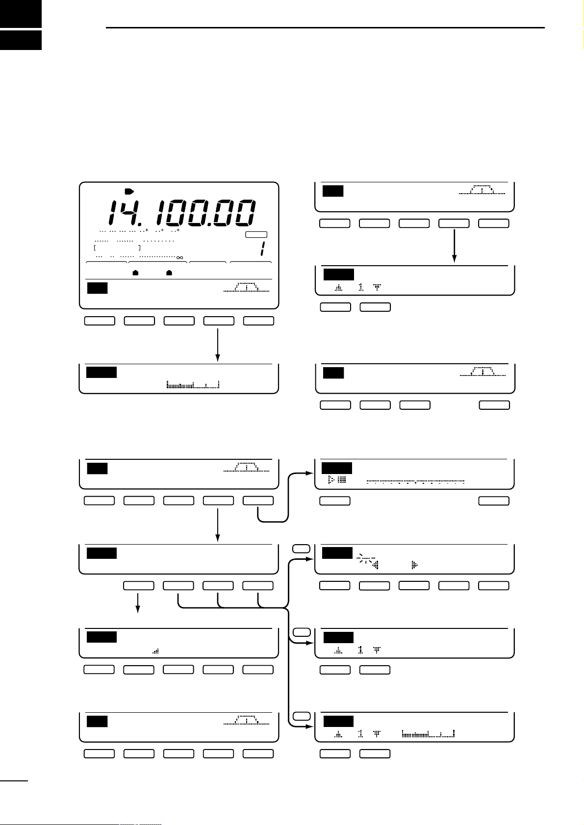
2-1
Menu set 1 flow chart
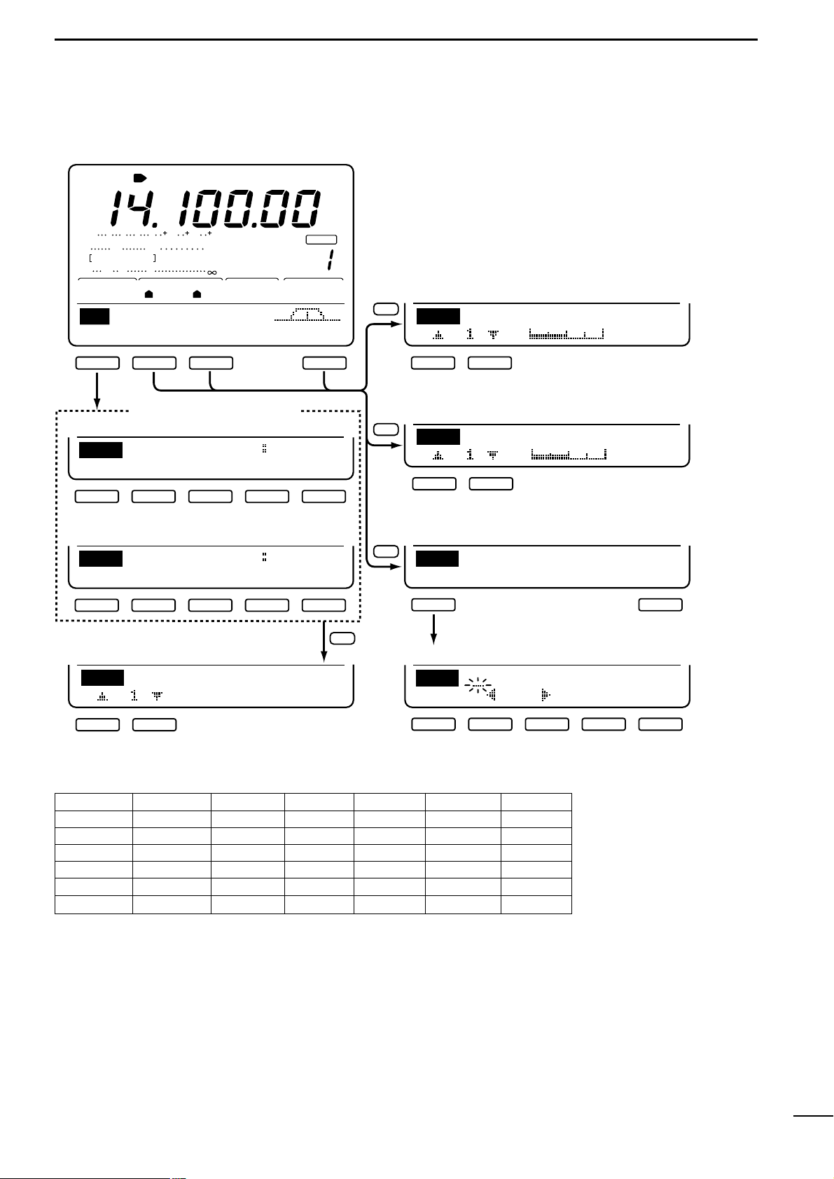
Pushing [MENU] toggles between menu set 1 (M1)
and menu set 2 (M2) in the function display.
Depending on the mode and menu item selected, the
action of the multi-function keys ([F1] to [F5]) changes.
Page 11
9
2
MENU SELECTION
F5
F2
F3
F5
BLANK
CH
ANT
USB
AGCAMP
P.
SWR
ALC
Po
S
1
20 50
3
3211.5
579 20 40 60
100%
1
1
S
M2
SCNMEMLCDSET
F1
F2
F3 F5
SCN
10k
+
-
∂F
PRO∂FFINSPNSET
F1
F2
F3 F4 F5
SCN
10k
+
-
∂F
MEM∂FSELSPNSET
F-1
F-2
F-3 F-4 F-5
SCANSpeed
HIGH
SET
F1
F2
F1 F5
MEM
14.1000USB
EDT()SEL
EDT
ABC
DELSPC
F1
F2
F3 F4 F5
LCDContrast
50%
LCD
F1
F2
VFO MODE
MEMORY MODE
50%
BeepLevel
SET
F1
F2
VFOA
(p. 55)
SET MODE
SCAN SET MENU
LCD MENU
MEMORY NAME MENU
NAME EDIT MENU
(p. 53)
(p. 66)
(p. 53)
(p. 60)
SCAN MENU (pgs. 56–58)
2-2
Menu set 2 flow chart
MENU MODE F1 F2 F3 F4 F5
SSB q AGC w DUP e CMP r TCN t SCP
CW AGC DUP y 1/4 u KEY SCP
M1 RTTY AGC DUP 1/4 i RTY SCP
AM AGC DUP CMP SCP
FM AGC DUP o TON !0 TSQ SCP
M2 ALL !1 SCN !2 MEM !3 LCD !4 SET
q AGC (auto gain control) : p. 39
w DUP (duplex) : p. 35
e CMP (speech compressor) : p. 46
r TCN (tone control) : p.20
t SCP (band scope) : p. 37
y 1/4 (dial rate) : p. 39
u KEY (CW key) : p.24
i RTY (RTTY) : p.30
o TON (repeater tone) : p. 35
!0 TSQ (tone squelch) : p. 33
!1 SCN (scan) : p. 55
!2 MEM (memory names) : p. 53
!3 LCD (function display) : p.66
!4 SET (set mode) : p. 60
Page 12
10
3
BASIC OPERATION
3-1
Before operating
Å BEFORE APPLYING POWER
Before applying power for the first time, check the following points:
➥ Is the connected external power supply capable of
delivering more than 20 A?
➥ Are the antenna(s) connected properly?
• [ANT1/2]: HF/50 MHz antenna
• [144MHz]: 144 MHz antenna
➥ Is the transceiver properly grounded? (p.70)
➥ Is external equipment, such as a linear amplifier
connected properly? (p.79)
➥ Make sure the front panel switches and controls are
set as illustrated below.
F1 F2 F3 F4 F5
PHONES
TRANSMIT
POWER
TUNER ANT
ELEC-KEY
MIC
M-CH
V/M CALL
M VFO
LOCK
XFC
TWIN PBT
NR APF/ANF
AF RF/SQL
NR APF
RIT/ TX
MIC GAIN RF PWR CW PITCH P.AMP/ATTKEY SPEED NB VOX/BK-IN MONITOR
SPEECH LOCK
TX RX
MENU SSB
CW/RTTY
AM/FM FILTER
MW
MP-W
HF/VHF TRANSCEIVER
MP-R TS
M-CL
RIT TX CLEAR
1.813.527
3
10414518
144ENT
6
21
7
24828
9
GENE
50
0
A/B
SPLIT
F-INP
Rearpanel
1
2
3
4
5
6
789
!0
q Rotate [NR] max. counterclockwise.
w Set [APF] to the center position.
e Set [TWIN PBT] to the center position.
r Rotate [AF] max. counterclockwise.
t Set [RF/SQL] to the center position.
y Rotate [MIC GAIN] max. counterclockwise.
u Rotate [RF PWR] max. counterclockwise.
i Set [CW PITCH] to the center position.
o Rotate [KEY SPEED] max. counterclockwise.
!0 Rotate [COMP GAIN] max. counterclockwise.
Page 13
11
3
BASIC OPERATION
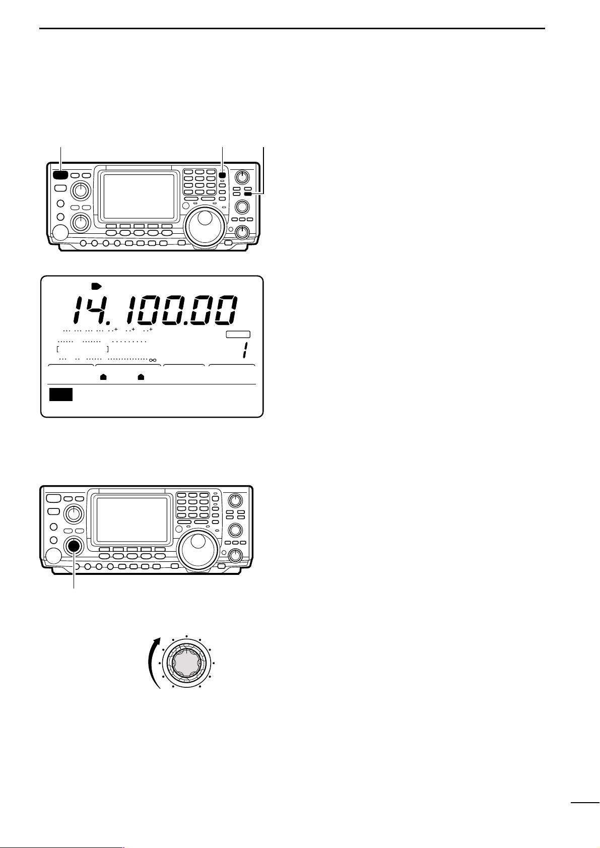
ı APPLYING POWER
Ç ADJUSTING VOLUME
Rotate [AF] to obtain a comfortable listening level.
• Clockwise rotation increases audio output; counterclockwise decreases audio output.
When applying power to the transceiver for the first
time, it’s a good idea to reset the CPU (see p. 81 for
details) as follows:
While pushing [F-INP] + [M-CL], push [POWER] to turn
power ON.
• After the CPU has been reset, turn power ON by pushing
[POWER] only.
• Push [POWER] for 1 sec.to turn power OFF.
[F-INP]
[M-CL]
[POWER]
BLANK
CH
ANT
USB
AGCAMP
P.
SWR
ALC
Po
S
1
20 50
3
3211.5
579 20 40 60
100%
1
1
S
M1
AGCDUPCMPTCNSCP
VFOA
☞ NOTE: When first applying power or when operat-
ing in cold environments, the display may flicker or
appear faint.This is normal and will disappear once
the transceiver has warmed up.
[AF]
Increasing audio
output
Page 14

12
3
BASIC OPERATION
3-2
Squelch and receive (RF)
sensitivity
[RF/SQL]
RF gain
range
RF gain
operating
range
Squelch
open
Squelch
threshold
Squelch
open
S-meter
squelch
range
S-meter squelch
operating
range
S-meter squelch
threshold
Noise squelch
range
Noise squelch
operating range
RF gain
max.
sensitivity
Max.
RF gain
sensitivity
Minimum
RF gain
sensitivity
Max. RF gain
Adjusts the RF gain and squelch threshold level. The
squelch removes noise output from the speaker
(closed condition) when no signal is received.
• The squelch is particularly effective for FM. It is also available for other modes.
• The control can be set as the RF gain control only (squelch
is fixed open) or squelch control (RF gain is fixed at maximum) in set mode (p.61). See below left.
• The 11 to 12 o’clock position is recommended for any setting of the [RF/SQL] control.
When setting as RF gain/squelch control
When setting as RF gain (squelch is fixed open)
Adjusting RF gain (receive sensitivity)
Normally, [RF/SQL] is set to the 11 o’clock position.
Rotate [RF/SQL] to the 11 o’clock position for maximum sensitivity.
• Rotating counterclockwise from the maximum position reduces sensitivity.
• The S-meter indicates receive sensitivity.
When setting as squelch (RF gain is fixed at max.)
Adjusting squelch (removing non-signal noise)
Rotate [RF/SQL] clockwise, when receiving no signal,
until the noise just disappears.
• [RX] indicator light goes out.
• Rotating [RF/SQL] past the threshold point invokes the S-
meter squelch—this allows you to set a minimum signal
level needed to open the squelch.
SET MODE
RF + SQL
(default)
SQL
RF
OPERATION
Can be used in all modes.
Functions as noise squelch or Smeter squelch in FM; S-meter
squelch only in other modes.
➥ Operates as a squelch control.
• RF gain is fixed at max.sensitivity.
➥ Operates as an RF gain control.
• Squelch is fixed open.
Page 15

13
3
BASIC OPERATION
3-3
Selecting VFO/memory mode
[V/M]
■ VFO DISPLAY (default)
BLANK
CH
ANT
USB
AGCAMP
P.
SWR
ALC
Po
S
1
20 50
3
3211.5
579 20 40 60
100%
1
1
S
M1
AGCDUPCMPTCNSCP
VFOA
■ MEMORY DISPLAY (default)
CH
AGCAMP
P.
SWR
ALC
Po
S
1
20 50
3
3211.5
579 20 40 60
100%
1
S
M1
AGCDUPCMPTCNSCP
MEMO
BLANK
[A/B]
Rotating the tuning dial selects frequencies in VFO
mode or pre-programmed memories in memory mode.
Push [V/M] to toggle between memory and VFO
modes.
• Pushing [V/M] for 2 sec. transfers the contents of the selected memory channel to VFO mode (p.50).
3-4
Toggling between VFO A/B
and transferring contents
In VFO mode, VFO A or VFO B can be selected.In addition, contents can be transferred between them.
➥ Push [A/B] to toggle between VFO A and VFO B.
➥ Push [A/B] for 1 sec. to transfer the contents of the
displayed VFO to the undisplayed VFO.
BLANK
CH
ANT
USB
AGCAMP
P.
SWR
ALC
Po
S
1
20 50
3
3211.5
579 20 40 60
100%
1
1
S
M1
AGCDUPCMPTCNSCP
VFOA
■ WHEN OPERATING IN VFO A
BLANK
CH
ANT
USB
AGCAMP
P.
SWR
ALC
Po
S
1
20 50
3
3211.5
579 20 40 60
100%
1
1
S
M1
AGCDUPCMPTCNSCP
VFOB
■ WHEN OPERATING IN VFO B
Page 16

14
3
BASIC OPERATION
3-5 Setting a band and frequency
Å SETTING AN OPERATING BAND
The transceiver has a triple band stacking register.This
means that the last 3 operating frequencies and
modes used on a particular band are automatically
memorized.
See the table below f or a list of the bands a vailable and
the default settings for each register.
Bandkeys
1.8
1
3.5
2
7
3
10
4
14
5
18
144ENT
6
21
7
•
24
8
28
9
GENE
50
0
■ USING THE BAND STACKING REGISTERS
[EXAMPLE]: 21 MHz band
➀ Push [21¶], then select a frequency and an operat-
ing mode.
• Frequency and operating mode are memorized in the
first band stacking register.
➁ Push [21¶] again, then select another frequency
and operating mode.
• This frequency and operating mode are memorized in
the second band stacking register.
➂ Push [21¶] again, then select another frequency
and operating mode.
• This frequency and operating mode are memorized in
the third band stacking register.
• When a fourth frequency and operating mode are selected on a band, the first register is overwritten.
BAND REGISTER 1 REGISTER 2 REGISTER 3
1.9 MHz 1.900000 CW 1.910000 CW 1.915000 CW
3.5 MHz 3.550000 LSB 3.560000 CW 3.580000 LSB
7 MHz 7.050000 LSB 7.060000 CW 7.020000 CW
10 MHz 10.120000 CW 10.130000 CW 10.140000 CW
14 MHz 14.100000 USB 14.200000 USB 14.050000 CW
18 MHz 18.100000 USB 18.130000 USB 18.150000 USB
21 MHz 21.200000 USB 21.300000 USB 21.050000 CW
24 MHz 24.950000 USB 24.980000 USB 24.900000 CW
28 MHz 28.500000 USB 29.500000 USB 28.100000 CW
50 MHz 50.100000 USB 50.200000 USB 51.100000 FM
145 MHz 145.000000 USB 145.100000 FM 145.200000 FM
General 15.000000 USB 15.100000 USB 15.200000 USB
Page 17
15
3
BASIC OPERATION
ı SETTING A FREQUENCY WITH THE
TUNING DIAL
Frequencies can be selected with the tuning dial or directly with the keypad (p. 17). When using the tuning
dial, the frequency changes according to the set tuning step.Tuning step defaults differ depending on operating mode as shown below.
SSB/CW/RTTY: 10 Hz
AM: 1 kHz
FM: 10 kHz
➥ Rotate the tuning dial clockwise to increase the fre-
quency; counterclockwise to decrease the frequency.
Tuning dial
■ BAND EDGE WARNING BEEPS
When selecting a frequency that lies outside of a
band’s specified frequency range, a warning beep
sounds.
This function can be turned off in set mode, if desired
(p.61).
Tuning steps automatically change according to the
rate at which the tuning dial is rotated.
When rotated slowly, one complete revolution of the
tuning dial changes the frequency 5 kHz (10 Hz tuning
steps); when rotated quickly, one complete revolution
of the tuning dial changes the frequency 25 kHz (50
Hz tuning steps).
Rotate the tuning dial to change the frequency in 10
Hz steps or use the microphone [UP]/[DN] keys to
change the frequency in 50 Hz steps. The diagram
below illustrates how to change the tuning steps.
■ AUTO TUNING STEPS
■ CHANGING TUNING STEPS
TS function OFF
Fine tuning
(
1
Hz)
TS function OFF
(1 kHz)*
*FM mode only 10 kHz
TS set mode
(0.1, 1, 5, 9, 10,
12.5, 20, 25 kHz)
SSB/CW/RTTY mode only
All modes
[TS]
momentarily
[TS]
momentarily
[TS]
2 sec.
[TS]
2 sec.
[TS]
2 sec.
• Using the [TS] switch
Page 18

16
3
BASIC OPERATION
■ TOGGLING THE TS FUNCTION ON AND OFF The tuning step function can be turned ON and OFF.
When the TS function is ON (default), rotating the tuning dial changes the frequency in the set tuning steps.
➀ Push [TS] to turn the tuning step function ON, if nec-
essary.
• The TS indicator, “Z” appears.
➁ Rotate the tuning dial to change the frequency ac-
cording to the set tuning step.
➂ Push [TS] again to turn the tuning step function
OFF.
• The TS indicator, “Z” disappears.
■ TUNING STEP PROGRAM MODE When the tuning step function is ON, tuning step pro-
gram mode can be selected. This mode is used to
change the set tuning steps.
➀ While the tuning step function is ON, (“Z” appears),
push [TS] for 2 sec. to enter tuning step program
mode.
➁ Rotate the tuning dial to select the desired tuning
step.
• 0.1, 1, 5, 9, 10, 12.5, 20 and 25 kHz can be selected.
• Tuning steps can be set individually for each operating
mode.
➂ Push [TS] again to exit tuning step program mode.
■ 1 Hz TUNING For critical tuning, a 1 Hz tuning step can be selected.
➀ While the tuning step function is OFF, (“Z” does not
appear), push [TS] for 2 sec.
• The 1 Hz indicator appears.
➁ Rotate the tuning dial to change the frequency in 1
Hz steps.
• When changing the frequency via the microphone, the
frequency changes in 50 Hz steps, regardless of whether
the 1 Hz tuning step is selected or not.
➂ Push [TS] for 2 sec. again (while the tuning step
function is OFF) to turn the 1 Hz tuning step OFF.
Tuning dial
[TS]
BLANK
CH
VFOA
ANT
AGCAMP
P.
SWR
ALC
Po
S
1
20 50
3
3211.5
579 20 40 60
100%
1
1
S
M1
F
USB
TS indicator
AGCDUPCMPTCNSCP
BLANK
CH
VFOA
ANT
AGCAMP
P.
SWR
ALC
Po
S
1
20 50
3
3211.5
579 20 40 60
100%
1
1
S
0.1kHz
SSB
TS
F
USB
TS indicator
BLANK
CH
ANT
USB
AGCAMP
P.
SWR
ALC
Po
S
1
20 50
3
3211.5
579 20 40 60
100%
1
1
S
M1
AGCDUPCMPTCNSCP
VFOA
The tuning step defaults are:
SSB/CW/RTTY: 10 Hz
AM: 1 kHz
FM: 10 kHz
Page 19
17
3
BASIC OPERATION
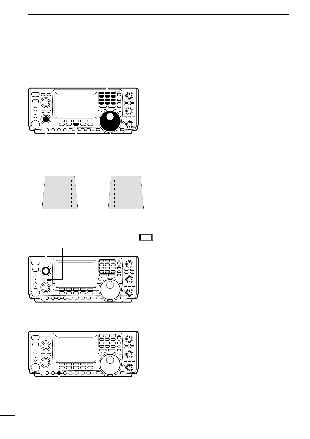
Ç SETTING A FREQUENCY VIA THE KEYPAD
The keypad can be used to enter frequencies directly.
➀ Push [F-INP] to activate keypad input.
➁ Enter the desired frequency using the correspond-
ing digit keys on the keypad.
• The displayed frequency is cleared and input starts at the
far right of the frequency display.
• Input “•” (decimal point) between the MHz units and kHz
units.
• Push [F-INP] to cancel input and return to the previous
frequency.
➂ When the desired frequency is input, push [144ENT]
to set the displayed frequency.
Keypad
[F-INP]
Lights when keypad input is activated
3-6
Selecting an operating mode
Each push of a mode key changes the operating frequency. In addition, in CW and RTTY modes, pushing
[CW/RTTY] for 2 sec. toggles between reverse and
normal modes.
SSB mode
Above 10 MHz, USB is automatically selected; below
10 MHz, LSB is automatically selected.
CW mode
Use CW-R mode when nearby BFO frequencies are
causing interference.
RTTY mode
When an all mode TNC is connected, RTTY(FSK) operation is possible.
[SSB]
[CW/RTTY]
[AM/FM]
[EXAMPLES]:
Setting 7.000000 MHz
Push [F-INP] + [21¶] + [144ENT]
Setting 14.025000 MHz
Push [F-INP] + [1.8¬]+[10¢] + [GENE(•)] + [50Ø]+
[3.5™]+[14∞] + [144ENT]
Setting 145.500000 MHz
Push [F-INP] + [1.8¬)] + [10¢] + [14∞] + [GENE(•)] +
[14∞] + [144ENT]
Setting 145.500000 MHz from 145.360000 MHz
Push [F-INP] + [GENE] + [7£)] + [18§] + [144ENT]
MODE KEY
[SSB]
[CW/RTTY]
[AM/FM]
MOMENTARY PUSH
Toggles between LSB and USB
Toggles between CW and RTTY
Toggles between AM and FM
PUSH FOR 2 SEC.
No function
Toggles between CW and CW-R or RTTY and RTTY-R
No function
Page 20

18
4
USING DIFFERENT OPERATING MODES
4-1 Operating SSB
Å RECEIVING
➀
Push a band key to select the desired band.
➁ Push [SSB] to select LSB or USB.
• Below 10 MHz LSB is automatically selected; above 10
MHz USB is automatically selected.
➂ Rotate [AF] to set audio to a comfortable listening
level.
➃ Rotate the tuning dial to tune a desired signal.
• S-meter indicates received signal strength.
[BAND]
[DIAL][SSB][AF]
✔Convenient functions for receive
q Preamp and attenuator (p.38) The preamp amplifies received signals in the front end
circuit to improve the S/N ration and sensitivity.The at-
tenuator prevents a desired signal from distorting
when very strong signals are near the desired frequency or when very strong electric fields, such as
from a broadcasting station, are near you.
w Noise blanker (p.39) The noise blanker is used to reduce pulse-type noise
caused by vehicle ignition systems and k e y clicks from
strong CW signals on nearby frequencies.
e Noise reduction (p.40) The noise reduction function reduces noise compo-
nents and picks out desired signals which are buried
in noise. This function digitally transposes receive
audio components to produce desired AF frequency
characteristics at the IF stage.
r Auto notch filter (p.40) The auto notch function automatically attenuates more
than 3 beat tones, tuning signals, etc., even if they are
moving.
t Twin PBT (passband tuning) (p.41) The PBT function electronically narrows the receiv er’s
IF passband widths to reduce interference. Moving
both [TWIN PBT] controls to the same position shifts
the IF.
y AGC (auto gain control) (p.39) The AGC controls receiver gain to produce a constant
audio output level even when the received signal
strength is varied by fading, etc.
DSP
DSP
Page 21
19
4
USING DIFFERENT OPERATING MODES
Band keys
[MIC GAIN]
[SSB]
[RF PWR]
Microphone connector
ALC
Po
S
1
20 50
3 5 7 9 20 40 60
100%
ALC zone
[TRANSMIT]
[SSB]
[MENU] Tuning Dial
TCN
LH
0
SSBTXTone
• Tone control menu
ı TRANSMITTING
Before transmitting, monitor your selected operating
frequency to make sure transmitting won’t cause interference to other stations on the same frequency.
➀ Connect the microphone to the [MIC] connector.
➁ Push a band key to select the desired operating
band.
➂ Push [SSB] to select LSB or USB.
➃ Rotate [RF PWR] to select output power.
➄ Push [TRANSMIT] or [PTT] to transmit.
• Talk into the microphone at your normal voice level.
• If necessary, adjust microphone gain with [MIC GAIN] so
that the ALC meter reading doesn’t go outside the ALC
zone (see left).
➅ Push [TRANSMIT] again or release [PTT] to return
to receive.
■ ADJUSTING TRANSMIT SIGNAL TONE
The tone of your transmitted signal can be adjusted to
suit your preference.In addition, the speech compressor function (p. 46) can be used to increase your talk
power.
➀ Push [SSB] to select LSB or USB.
➁ Push [MENU] to select M1.
➂ Push [F4] to display the tone control menu.
➃ Push [MONI] to turn the monitor function on.
•“MONI” appears.
➄ While pushing [PTT] and speaking into the micro-
phone, rotate the tuning dial to vary the tone of your
transmitted signal.
• Clockwise rotation increases the tone; counterclockwise
rotation decreases the tone.
➅ Push [MENU] to return to M1.
✔Convenient functions for transmit
q Speech compressor (p.46) The speech compressor compresses the transmitter
audio input to increase the average audio output le v el.
Therefore, talk power is increased. This function is effective for long distance communication or when propagation conditions are poor.
w VOX (voice activated transmit) (p.43) The VOX function starts transmission without pushing
the transmit switch or PTT s witch when y ou speak into
the microphone; then, automatically returns to receive
when you stop speaking.
e Transmit quality monitor (p. 45) This function allows you to monitor the quality of your
transmitted signal.
Page 22
20
4
USING DIFFERENT OPERATING MODES
4-2 Operating CW
Å RECEIVING
Band keys
[CW/RTTY]
[AF]
[DIAL]
Normal Reverse
interferenceBFOinterference
signal
BFO
signal
[APF] [APF/ANF]
[CW PITCH]
➀ Push a band key to select the desired band.
➁ Push [CW/RTTY] to select CW or CW-R.
• Push [CW/RTTY] for 2 sec. to toggle between CW and
CW-R modes.
➂ Rotate [AF] to set audio to a comfortable listening
level.
➃ Rotate the tuning dial to simultaneously tune a sig-
nal and its side tone.
• S-meter indicates received signal strength.
■ ABOUT CW REVERSE MODE
■ ABOUT THE AUDIO PEAK FILTER
■ ABOUT THE CW PITCH CONTROL
The received CW audio pitch and monitored CW audio
can be adjusted to suit your preferences (300 to 900
Hz in 3 Hz steps) without changing the operating frequency.
➥ Rotate [CW PITCH] clockwise to increase the pitch
frequency; counterclockwise to decrease the pitch
frequency.
☞ NOTE: When adjusting the CW pitch and the audio
peak frequency is ON (see above), the center frequency of the audio peak filter may have to be
readjusted. Otherwise, receive audio may not be
emitted.
The APF changes the receive frequency response by
boosting a particular frequency for better copying of
desired CW signals. The peak frequency can be adjusted from 300 to 900 Hz manually. The boost frequency width can be selected from 80, 160 or 320 Hz.
➀ Push [APF/ANF] to turn the audio peak filter ON.
➁ Push [APF/ANF] for 2 sec., one or more times, to
select the filter width.
• W=320 Hz, M=160 Hz, N=80 Hz.
➂ Rotate the [APF] control to adjust the center fre-
quency of the peak frequency.
CW reverse mode receives CW signals with a reverse
side CW carrier point like that of LSB and USB modes.
Use this mode when interfering signals are near the
desired signal and you want to change the interference
tone.
DSP
Page 23

21
4
USING DIFFERENT OPERATING MODES
✔Convenient functions for receive
q Preamplifier and attenuator (p.38) The preamp amplifies received signals in the front end
circuit to improve the S/N ration and sensitivity.The at-
tenuator prevents a desired signal from distorting
when very strong signals are near the desired frequency or when very strong electric fields, such as
from a broadcasting station, are near you.
w Noise blanker (p.39) The noise blanker is used to reduce pulse-type noise
caused by vehicle ignition systems and k e y clicks from
strong CW signals on nearby frequencies.
e Noise reduction (p.40) The noise reduction function reduces noise compo-
nents and picks out desired signals which are buried
in noise. This function digitally transposes receive
audio components to produce desired AF frequency
characteristics at the IF stage.
r Twin PBT (passband tuning) (p.41) The PBT function electronically narrows the receiv er’s
IF passband widths to reduce interference. Moving
both [TWIN PBT] controls to the same position shifts
the IF.
t AGC (auto gain control) (p.39) The AGC controls receiver gain to produce a constant
audio output level even when the received signal
strength is varied by fading, etc.
y 1/4 function (p. 39) Normally, one rotation of the tuning dial changes the
frequency by about 5 kHz (in 10 Hz tuning steps).
Using the 1/4 function sets the tuning dial so that one
rotation changes the frequency by about 1.25 kHz (in
10 Hz steps).This is convenient for critical tuning.
DSP
Page 24
22
4
USING DIFFERENT OPERATING MODES
Band keys
[RF PWR]
[CW/RTTY]
[TRANSMIT]
[KEY SPEED]
ı TRANSMITTING
Before transmitting, monitor your selected operating
frequency to make sure transmitting won’t cause interference to other stations on the same frequency.
➀ Connect an electronic keyer or paddle to the [ELEC-
KEY] jack on the rear panel of the transceiver
(p.68).
➁ Push a band key to select the desired band.
➂ Push [CW/RTTY] to select CW or CW-R.
• Push [CW/RTTY] for 2 sec. to toggle between CW and
CW-R modes.
➃ Rotate [AF] to set audio to a comfortable listening
level.
➄ Push [TRANSMIT] to set the transceiver to the
transmit condition.
➅ Use the electronic keyer or paddle to key your CW
signals.
• The P0
meter indicates transmitted CW signal strength.
■ ABOUT KEYING SPEED
■ CW SIDE TONE FUNCTION
The transceiver’s inter nal electronic keyer speed can
be adjusted from 6 to 60 wpm.
➥ Rotate [KEY SPEED] clockwise to increase keying
speed; counterclockwise to decrease keying speed.
When the transceiver is in the receive condition (and
the break-in function is OFF—p. 44) you can listen to
the tone of your CW signal without actually transmitting.This allows you to match your transmit signal exactly to another station’s.This also convenient for CW
practice.CW side tone level can be adjusted in CW set
mode (p.27).
✔Convenient functions for transmit
Break-in function (p.44) The break-in function automatically toggles the trans-
ceiver between transmit and receive when operating
CW. This function can be set to full break-in or semi
break-in.
Page 25

23
4
USING DIFFERENT OPERATING MODES
M1M2M3M4 -1
F1
F2
F3 F4 F5
F2
F3 F4 F5
SNDEDT001SET
KEY
F1
F2
F3 F4 F5
001
SND
50%
SideToneLevel
SET
F1
F2
Normal
NumberStyle
001
F1
F2
F1
F2
F3 F4 F5
EDT
M1
DELSPC
CQTESTCQTEST
F5
F4
F3
BLANK
1
4
CH
VFOA
ANT
AGCAMP
P.
SWR
ALC
Po
S
1
20 50
3
3211.5
579 20 40 60
100%
NAR
1
1
F
CW
M1
AGCDUP1/4KEYSCP
Memory keyer menu
Keyer set (SET) menu
Contest number (001) menu
Edit (EDT) menu
Transmit (SND) menu
Ç ELECTRONIC KEYER FUNCTIONS
The transceiver has a number of convenient functions
for the electronic keyer that can be accessed from the
memory keyer menu.
➀ Push [CW/RTTY] to select CW mode.
➁ Push [MENU] to select M1.
➂ Push [F4] to select the memory keyer menu.
➃ Push one of the multi-function keys ([F1] to [F5]) to
select an item in the memory keyer menu. See the
diagram below.
(1) Memory keyer settings menu
■ IN CW MODE
Page 26
24
4
USING DIFFERENT OPERATING MODES
BLANK
1
4
CH
VFOA
ANT
AGCAMP
P.
SWR
ALC
Po
S
1
20 50
3
3211.5
579 20 40 60
100%
NAR
1
1
F
CW
001
SND
M1M2M3M4 -1
F2
UR5NN001B001
SND
M1M2M3M4 -1
F1 F3 F4 F5
CQTESTCQ001
SND
M1M2M3M4 -1
[
]
CQTESTCQ001
SND
M1M2M3M4 -1
F1
Sending contents of F1(M1) to F4(M4)
M2 send indication
M1 send indication
Repeat send indication
repeat indicators
Count up
trigger indicator
Count down indicator
UR5NN001B001
SND
M1M2M3M4 -1
F2
M1M2M3M4 -1
CFMTU002
SND
F3
M1M2M3M4 -1
QRZ?002
SND
F4
M3 send indication
M2 send indication
M4 send indication
(2) Memory keyer send menu
Pre-set characters can be sent using the memory
keyer send menu. Contents of the memor y keyer are
set using the edit menu.
➀ Push [TRANSMIT] to set the transceiver to transmit,
or set the break-in function ON (p.44).
• When the transceiver is in receive, step ➁ monitors the
memory keyer contents, but does not transmit them.
➁ Push one of the function keys ([F1] to [F4]) to send
the contents of the memory keyer.
• The currently active memory keyer contents is indicated
by a triangle beside it.
• Pushing a function key for 2 sec. repeatedly sends the
contents; push any function key to cancel the transmission.
• The contest number counter, above [F5], is incremented
each time the contents are sent.
• The contest number trigger can be set in the contest
number menu.
• Push [F5] to manually increment the contest number.
➂ Push [MENU] 2 times to return to M1.
■ TRANSMITTING
Send menu
Page 27
25
4
USING DIFFERENT OPERATING MODES
BLANK
1
4
CH
VFOA
ANT
AGCAMP
P.
SWR
ALC
Po
S
1
20 50
3
3211.5
579 20 40 60
100%
NAR
1
1
F
CW
F1
F2
F3 F4 F5
EDT
M1
DELSPC
CQTESTCQTEST
EDT
M2
DELSPC
UR5NN*BK
UR5NN*BK
EDT
M3
DELSPC
CFMTU
EDT
M4
DELSPC
QRZ?
Input space
Clear characterMove cursor left/right
Select M1 to M4
• M2 indication
Edit (EDT) menu
• M3 indication
• M4 indication
When inputting an asterisk,
the counter is incremented by 1.
EDT
M3
DELSPC
QSLTUDEJA3Y
EDT
M3
DELSPC
DEJA3YUATEST
• Example display when inputting
(3) Memory keyer edit menu
■ PROGRAMMING CONTENTS
The contents of the memory keyer memories can be
set using the memory keyer edit menu.The memor y
keyer can memorize and re-transmit 4 CW key codes
for often-used CW sentences, contact numbers, etc.
Total capacity of the memory keyer is 50 characters
per memory channel.
➀ Push [F1]M1 to select memory for editing.
➁ Input the desired character by rotating the tuning
dial or by pushing the keypad for number input.
• All uppercase letters of the alphabet can be selected as
well as “/”“?”“^”“.”“,” and “*”.
➂ Push [F2] or [F3] to move the cursor backwards or
forwards, respectively.
➃ Repeat steps ➁ and ➂ to input the desired charac-
ters.
➄ Push [MENU] 2 times to return to regular operation.
☞ NOTE: “^” is used to transmit a following word with
no space such as AR. Put “^” before a text string
such as ^AR, and the string “AR” is sent with no
space.
☞ NOTE: “M” is used to inser t the CW contact num-
ber.The contact number automatically increments
by 1.This function is only availab le for one memory
keyer channel at a time .Memory keyer channel M2
uses “M”by default.
About the contents of M2
Pre-programmed contents
MCH CONTENTS
M1 CQ TEST CW TEST DE JA1 JA1 TEST
M2 UR 5NNM BK
M3 CFM TU
M4 QRZ?
Page 28

26
4
USING DIFFERENT OPERATING MODES
BLANK
CH
VFOA
ANT
AGCAMP
P.
SWR
ALC
Po
S
1
20 50
3
3211.5
579 20 40 60
100%
1
1
S
Normal
NumberStyle
001
F1
F2
F3 F4 F5
CW
F
Set item up/down
Normal
NumberStyle
001
M2
CountUpTrig
001
CLR001
PresentNumber
001
(4) Contact number menu
This menu is used to set the contact (serial) number
and count up trigger, etc.
➀ Push [F1] or [F2] to select the set contents.
➁ Rotate the tuning dial to set the condition.
• See below for details.
➂ Push [MENU] 2 times to return to regular operation
(M1).
This item sets the numbering system used for contact (serial) numbers—normal or morse cut numbers.
• Normal: does not use morse cut numbers (default).
• 190➞ANO: sets 1 as A, 9 as N and Ø as O.
• 190➞ANT: sets 1 as A, 9 as N and Ø as T.
• 90➞NO: sets 9 as N and Ø as O.
• 90➞NT: sets 9 as N and Ø as T.
This item sets the count up trigger channel.
• M1, M2, M3 or M4 can be set.
This item shows the current number for the count up
trigger channel set above.
• Rotate the tuning dial to change the number, or push
[F3](CLR) for 2 sec.to reset the current number to 001.
SET MODE ITEM AND DEFAULT CONDITION DESCRIPTION
Page 29

27
4
USING DIFFERENT OPERATING MODES
50%
SideToneLevel
SET
F1
F2
F3 F4 F5
Set item up/down
50%
SideToneLevel
SET
ON
SideToneL-lmt
SET
2s
RepeatTime
SET
1:1:3.0
Dot/DashRatio
SET
NORMAL
PaddlePolarity
SET
ELEC-KEY
KeyerType
SET
OFF
MICU/DKeyer
SET
(5) CW keyer set menu
This menu is used to set the CW side tone, memory
keyer repeat time, dash weight, paddle specifications,
keyer type, etc.
➀ Push [F1] or [F2] to select the set contents.
➁ Rotate the tuning dial to set the condition.
• See below for details.
➂ Push [MENU] 2 times to return to regular operation
(M1).
This item sets the CW side tone.
• 0 to 100% in 1% steps can be selected.
This item sets the CW side tone level limit.When the
[AF] control is rotated above a specified level, the
CW side tone does not increase.
• OFF: CW side tone level is not limited.
• ON: CW side tone level is limited.
When sending CW using the repeat timer, this item
sets the time between transmissions.
• 1, 2, 10 or 30 sec. can be selected.
This item sets the dash/dot ratio.
• 1:1:2.8 to 1:1:4.5 (in 0.12 steps) can be selected.
This item sets the paddle polarity.
• Normal and reverse polarity can be selected.
This item sets the keyer type.
• ELEC-KEY, BUG KEY and Straight can be selected.
This item allows you to set the microphone [UP]/[DN]
switches to be used as a paddle.
• ON: [UP]/[DN] switches can be used for CW.
• OFF: [UP]/[DN] switches cannot be used for CW.
☞ NOTE: When “ON” is selected, the frequency and
memory channel cannot be changed using the
[UP]/[DN] switches.
SET MODE ITEM AND DEFAULT CONDITION DESCRIPTION
Page 30

28
4
USING DIFFERENT OPERATING MODES
Band keys
[CW/RTTY]
[AF]
Tuning dial
Normal Reverse
170
Hz
170
Hz
2125
Hz
2125
Hz
BFOBFO
Space
Space
Mark
Mark
4-3 Operating RTTY (FSK)
Å RECEIVING
Before operating RTTY be sure to consult the manual
that came with your TNC.
➀ Connect RTTY capable TNC and personal computer
or an RTTY terminal (p.68)
➁ Push a band key to select the desired band.
➂ Push [CW/RTTY] to select RTTY.
➃ Rotate [AF] to set audio to a comfortable listening
level.
➄ Rotate the tuning dial to set the desired frequency.
• S-meter indicates received signal strength.
• If the received signal cannot be demodulated, try select-
ing RTTY-R mode.
■ ABOUT RTTY REVERSE MODE
Received characters are occasionally garbled when
the receive signal is reversed between MARK and
SPACE.This reversal can be caused by incorrect TNC
connections, setting, commands, etc.To receive a reversed RTTY signal correctly, select RTTY-R mode.
✔Convenient functions for receive
q Preamplifier and attenuator (p.38) The preamp amplifies received signals in the front end
circuit to improve the S/N ration and sensitivity.The at-
tenuator prevents a desired signal from distorting
when very strong signals are near the desired frequency or when very strong electric fields, such as
from a broadcasting station, are near you.
w Noise blanker (p.39) The noise blanker is used to reduce pulse-type noise
caused by vehicle ignition systems and k e y clicks from
strong CW signals on nearby frequencies.
e Noise reduction (p.40) The noise reduction function reduces noise compo-
nents and picks out desired signals which are buried
in noise. This function digitally transposes receive
audio components to produce desired AF frequency
characteristics at the IF stage.
r Twin PBT (passband tuning) (p.41) The PBT function electronically narrows the receiv er’s
IF passband widths to reduce interference. Moving
both [TWIN PBT] controls to the same position shifts
the IF.
t AGC (auto gain control) (p.39) The AGC controls receiver gain to produce a constant
audio output level even when the received signal
strength is varied by fading, etc.
y 1/4 function (p. 39) Normally, one rotation of the tuning dial changes the
frequency by about 5 kHz (in 10 Hz tuning steps).
Using the 1/4 function sets the tuning dial so that one
rotation changes the frequency by about 1.25 kHz (in
10 Hz steps).This is convenient for critical tuning.
DSP
Page 31

29
4
USING DIFFERENT OPERATING MODES
Band keys
[RF PWR]
[CW/RTTY]
[TRANSMIT]
Tuning dial
BLANK
CH
VFOA
ANT
AGCAMP
P.
SWR
ALC
Po
S
1
20 50
3
3211.5
579 20 40 60
100%
1
1
S
2125
RTTYMark
RTY
F1
F2
F
RTTY
Set item up/down
2125
RTTYMark
RTY
170
RTTYShift
RTY
NORMAL
RTTYKeying
RTY
ı TRANSMITTING
Ç SETTINGS FOR RTTY
Before transmitting, monitor your selected operating
frequency to make sure transmitting won’t cause interference to other stations on the same frequency.
➀ Connect RTTY capable TNC and personal computer
or an RTTY terminal (p.68)
➁ Push a band key to select the desired band.
➂ Push [CW/RTTY] to select RTTY or RTTY-R.
• Push [CW/RTTY] for 2 sec.to toggle between RTTY and
RTTY-R modes.
➃ Rotate [AF] to set audio to a comfortable listening
level.
➄ Push [TRANSMIT] to set the transceiver to the
transmit condition or transmit a SEND signal from
your TNC.
• The P0 meter indicates transmitted RTTY signal strength.
➅ Operate the connected PC or TNC (TU) to transmit
RTTY (FSK) signals.
Mark and shift frequencies as well as RTTY keying can
be set for RTTY operation.
➀ Push [F4](RTY) to select the RTTY menu.
➁ Push [F1] or [F2] to select the desired item.
➂Rotate the tuning dial to select the desired condition.
• See the table below.
➃ Push [MENU] 2 times to return to normal operation.
SET MODE ITEM AND DEFAULT CONDITION DESCRIPTION
Sets the mark frequency for RTTY operation.
• 1275, 1615 and 2125 Hz are selectable.
Sets the shift frequency for RTTY operation.
• 170, 200 and 425 Hz are selectable.
Sets the keying polarity for RTTY operation.
• NORMAL: key open=mark
key closed=space
• REVERSE: key open=space
key closed=mark
Page 32

30
4
USING DIFFERENT OPERATING MODES
Band keys
[AF]
Tuning dial
[AM/FM]
4-4 Operating AM
Å RECEIVING
➀
Push a band key to select the desired band.
➂ Push [AM/FM] to select AM.
• Pushing [AM/FM] toggles between AM and FM operation.
➂ Rotate [AF] to set audio to a comfortable listening
level.
➃ Rotate the tuning dial to set the desired frequency.
• S-meter indicates received signal strength.
• The default tuning step for AM mode is 1 kHz; this can
be changed using tuning step program mode (p.16).
✔Convenient functions for receive
q Preamplifier and attenuator (p.38) The preamp amplifies received signals in the front end
circuit to improve the S/N ration and sensitivity.The at-
tenuator prevents a desired signal from distorting
when very strong signals are near the desired frequency or when very strong electric fields, such as
from a broadcasting station, are near you.
w Noise blanker (p.39) The noise blanker is used to reduce wide pulse-type
caused by vehicle ignitions and key clicks from strong
CW signals on nearby frequencies. In some cases,
using the noise blanker may cause receive audio distortion.Turn the noise blanker off in such cases.
e Noise reduction (p.40) The noise reduction function reduces noise compo-
nents and picks out desired signals which are buried
in noise.The received AF signals are converted to digital signals and then the desired signals are separated
from the noise.
r Auto notch filter (p.40) The auto notch function automatically attenuates more
than 3 beat tones, tuning signals, etc., even if they are
moving.
r Twin PBT (passband tuning) (p.41) The PBT function electronically narrows the receiv er’s
IF passband widths to reduce interference. Moving
both [TWIN PBT] controls to the same position shifts
the IF.
t AGC (auto gain control) (p.39) The AGC controls receiver gain to produce a constant
audio output level even when the received signal
strength is varied by fading, etc.
DSP
DSP
Page 33

31
4
USING DIFFERENT OPERATING MODES
Band keys
[MIC GAIN]
[RF PWR]
Connect microphone here
[AM/FM]
[TRANSMIT]
ı TRANSMITTING
Before transmitting, monitor your selected operating
frequency to make sure transmitting won’t cause interference to other stations on the same frequency.
➀ Connect a microphone to the [MIC] connector.
➁ Push a band key to select the desired band.
➂ Push [AM/FM] to select AM.
• Pushing [AM/FM] toggles between AM and FM.
➃ Rotate [AF] to set audio to a comfortable listening
level.
➄ Push [TRANSMIT] or push and hold [PTT] to trans-
mit, then speak into the microphone to transmit.
• The P0 meter indicates transmitted AM signal strength.
➅ Push [TRANSMIT] or release [PTT] to return to re-
ceive.
✔Convenient functions for transmit
q Speech compressor (p.46) The speech compressor compresses the transmitter
audio input to increase the average audio output le v el.
Therefore, talk power is increased. This function is effective for long distance communication or when propagation conditions are poor.
w VOX (voice activated transmit) (p.43) The VOX function starts transmission without pushing
the transmit switch or PTT s witch when y ou speak into
the microphone; then, automatically returns to receive
when you stop speaking.
e Transmit quality monitor (p. 45) This function allows you to monitor the quality of your
transmitted signal.
Page 34

32
4
USING DIFFERENT OPERATING MODES
Band keys
[AF]
Tuning dial[AM/FM]
BLANK
CH
VFOA
ANT
AGCAMP
P.
SWR
ALC
Po
S
1
20 50
3
3211.5
579 20 40 60
100%
1
1
S
88.5Hz
ToneSQL
FM
TSQ
SCN
4-5 Operating FM
Å RECEIVING
➀
Push a band key to select the desired band.
➂ Push [AM/FM] to select FM.
• Pushing [AM/FM] toggles between AM and FM operation.
➂ Rotate [AF] to set audio to a comfortable listening
level.
➃ Rotate [SQL] to the point where audio noise is just
muted.
➄ Rotate the tuning dial to set the desired frequency.
• S-meter indicates received signal strength.
• The default tuning step for FM mode is 10 kHz;this can
be changed using tuning step program mode (p.16).
■ TONE SQUELCH OPERATION
■ TONE SCAN By monitoring a signal that is being transmitted on a
repeater input frequency, you can determine the tone
frequency necessary to open a repeater.
➀ Set tone squelch operation as in steps ➀ to ➁
above.
➁ Push [F4](SCN) to toggle the tone scan ON and
OFF.
•“Tone SQL SCAN” appears
➂ When a matched tone is found, a beep sounds and
the tone frequency is programmed into the selected
mode.
• Tone scan pauses when a tone frequency is detected.
Tone squelch operation is a method of communications using selective calling.Only received signals having a matching tone will open the squelch. Before
communicating using tone squelch, all members of
your party must agree on the tone squelch frequency
to use.
➀
While in FM mode, push [MENU] to select menu set 1.
➁ Push [F4](TSQ) for 2 sec.to select the tone squelch
frequency set menu.
➂ Rotate the tuning dial to select the desired tone
squelch frequency.
➃ Push [F4](TSQ) momentarily to turn the tone
squelch function ON or OFF.
•“TSQL” appears in the display when the function is ON.
➄ Communicate in the usual manner.
• Available tone squelch frequencies (unit:Hz)
91.5Hz
ToneSQL
SCAN
TSQ
Display during tone scan
SCN
F1
F2
F3 F4 F5
Push [F1](SCN) to start/stop tone scan.
67.0
69.3
71.9
74.4
77.0
79.7
82.5
85.4
88.5
91.5
94.8
97.4
100.0
103.5
107.2
110.9
114.8
118.8
123.0
127.3
131.8
136.5
141.3
146.2
151.4
156.7
159.8
162.2
165.5
167.9
171.3
173.8
177.3
179.9
183.5
186.2
189.9
192.8
196.6
199.5
203.5
206.5
210.7
218.1
225.7
229.1
233.6
241.8
250.3
254.1
Page 35

33
4
USING DIFFERENT OPERATING MODES
Band keys
[MIC GAIN]
[RF PWR]
Connect microphone here
[TRANSMIT]
[AM/FM]
ı TRANSMITTING
Before transmitting, monitor your selected operating
frequency to make sure transmitting won’t cause interference to other stations on the same frequency.
➀ Connect a microphone to the [MIC] connector.
➁ Push a band key to select the desired band.
➂ Push [AM/FM] to select FM.
• Pushing [AM/FM] toggles between AM and FM.
➃ Rotate [AF] to set audio to a comfortable listening
level.
➄ Push [TRANSMIT] or push and hold [PTT] to trans-
mit, then speak into the microphone to transmit.
➅ Push [TRANSMIT] or release [PTT] to return to re-
ceive.
✔Convenient functions for receive
q Preamplifier and attenuator (p.38) The preamp amplifies received signals in the front end
circuit to improve the S/N ration and sensitivity.The at-
tenuator prevents a desired signal from distorting
when very strong signals are near the desired frequency or when very strong electric fields, such as
from a broadcasting station, are near you.
w Noise reduction (p.39) The noise reduction function reduces noise compo-
nents and picks out desired signals which are buried
in noise.The received AF signals are converted to digital signals and then the desired signals are separated
from the noise.
e Auto notch filter (p.40) The auto notch function automatically attenuates more
than 3 beat tones, tuning signals, etc., even if they are
moving.
✔Convenient functions for transmit
q VOX (voice activated transmit) (p.43) The VOX function starts transmission without pushing
the transmit switch or PTT s witch when y ou speak into
the microphone; then, automatically returns to receive
when you stop speaking.
w Transmit quality monitor (p. 45) This function allows you to monitor the quality of your
transmitted signal.
DSP
DSP
Page 36

34
4
USING DIFFERENT OPERATING MODES
4-6 Repeater operation
BLANK
CH
VFOA
ANT
AGCAMP
P.
SWR
ALC
Po
S
1
20 50
3
3211.5
579 20 40 60
100%
1
1
S
FM
M1
AGCDUPTONTSQSCP
AGCAMP
P.
1
S
M1
29.55000
AGCDUPTONTSQSCP
T
DUP
88.5Hz
RptrTone
TON
A repeater amplifies received signals and retransmits
them at a different frequency. When using a repeater,
the transmit frequency is shifted from the receive frequency by an offset frequency. A repeater can be accessed using split frequency operation with the shift
frequency set to the repeater’s offset frequency.
➀ Push [A/B] to select VFO A.
➁ Push a band key to select the desired band.
➂ Push [AM/FM] to select FM mode.
• Pushing [AM/FM] toggles between AM and FM modes.
➃ Rotate the tuning dial to set the repeater transmit
frequency.
➄ While menu set 1 is selected, push [F2](DUP) one
or more times to set the offset direction.
• The offset frequency is set in advance in set mode.
➅ While menu set 1 is selected, push [F3](TON) to
turn the repeater tone function ON or OFF.
➅ When 1750 Hz European repeater tone is selected
in set mode as below, push [F3](TON) while transmitting to transmit 1750 Hz tone.
➆ Communicate in the normal way.
This function allows you to set repeater operation with
the push of one switch.
➥ To set the transceiver for repeater operation using
the one-touch repeater function, follow the steps
above but instead of steps ➄ and ➅ push [AM/FM]
for 2 sec.
■ ONE-TOUCH REPEATER FUNCTION
☞ NOTE: Set the offset shift direction and frequency
in advance (pgs. 60, 61) as well as the repeater
tone frequency (see below).
You may be able to receive the other par ty’s transmit
signal directly without having to go through a repeater.
This function allows you to check this.
➥ While receiving, push [XFC] to see if you can re-
ceive the other party’s transmit signal directly.
■ TRANSMIT FREQUENCY MONITOR CHECK
The transceiver’s repeater tone frequency is set to 88.5
Hz by default.This can be changed if desired.
➀ While menu set 1 is selected, push [F3](TON) for 1
sec. to select the repeater tone frequency menu.
➁ Rotate the tuning dial to select the desired fre-
quency (see table at left.)
• A 1750 Hz tone is available for operating European repeaters.
➂ Push [MENU] to return to menu set 1.
• Repeater tone frequency menu
■ REPEATER T ONE FREQUENCIES
M1
-100.0k
AGCDUPTONTSQSCP
67.0
69.3
71.9
74.4
77.0
79.7
82.5
85.4
88.5
91.5
94.8
97.4
100.0
103.5
107.2
110.9
114.8
118.8
123.0
127.3
131.8
136.5
141.3
146.2
151.4
156.7
159.8
162.2
165.5
167.9
171.3
173.8
177.3
179.9
183.5
186.2
189.9
192.8
196.6
199.5
203.5
206.5
210.7
218.1
225.7
229.1
233.6
241.8
250.3
254.1
1750
Page 37

35
4
USING DIFFERENT OPERATING MODES
This function automatically activates the repeater settings (DUP or DUP– and tone encoder ON/OFF) when
the operating frequency falls within the general repeater output frequency range and deactivates them
when outside of the range.
Set the auto repeater function ON-1 or ON-2 in set
mode in advance. (p. 62) When set ON, repeater settings are automatically activated according to the table
below.
ON-1 automatically sets the duplex setting and ON-2
automatically sets the duplex setting and tone encoder
automatically.
Frequency range and offset direction
➀ For the USA version, turn the auto repeater function
OFF in set mode.(p.62)
➁ Turn the quick split function ON in set mode. (p. 61)
➂ Push [AM/FM] to select FM mode.
• Pushing [AM/FM] toggles between AM and FM modes.
➃ Push [A/B] to select VFO A.
➄ Rotate the tuning dial to set the repeater output fre-
quency.
• Set the tuning step if desired.
➅ Push [A/B] to select VFO B.
➆ Rotate the tuning dial to set the repeater input fre-
quency.
➇ Push [A/B] to select VFO A.
➈ Push [SPLIT] to turn the split function ON.
➉ Push [F3](TON) to tur n the previously set tone en-
coder ON.
!1 Push [MW] for 2 sec.to store the contents in the se-
lected memory channel.
■ AUTO REPEATER FUNCTION
☞ NOTE: This function is available for the USA ver-
sion only.
■ STORING A NON STANDARD REPEATER
FREQUENCY RANGE
145.200–145.495 MHz
146.610–146.995 MHz
147.000–147.395 MHz
DUPLEX DIRECTION
minus duplex
minus duplex
plus duplex
Page 38

36
4
USING DIFFERENT OPERATING MODES
4-7 Packet operation
Å RECEIVING
Band keys
[AF]
Tuning dials[SSB] [AM/FM]
Band keys
[MIC GAIN]
[SSB]
[RF PWR]
[AM/FM]
200 Hz
2125 Hz
2325 Hz
1000 Hz
2200 Hz
1200 Hz
Carrier point
Before operating pack et (AFSK) be sure to consult the
operating manual that came with your TNC.
➀ Connect a TNC and personal computer (p.68)
➁ Push a band key to select an operating band.
➂ Push a mode key to select an operating mode.
• Generally, LSB is used for packet operation on the HF
bands and FM is used for packet operation on the VHF
band.
➃ Rotate [AF] to set the audio to a comfortable listen-
ing level.
➄ Rotate the tuning dial to tune the desired signal.
• Received signal strength is indicated in the S-meter.
ı TRANSMITTING
Before transmitting, monitor your selected operating
frequency to make sure transmitting won’t cause interference to other stations on the same frequency.
➀ Connect a TNC and personal computer (p.68)
➁ Push a band key to select an operating band.
➂ Push a mode key to select an operating mode.
• Generally, LSB is used for packet operation on the HF
bands and FM is used for packet operation on the VHF
band.
➃ Rotate [RF PWR] to set the output power.
• Relative strength of the transmitted signal is indicated in
the P
0 meter while operating the TNC.
• When operating in SSB mode, adjust output power so
that the ALC reading in the ALC meter stays in the ALC
zone.
➄ Transmit your AFSK signals using your computer’s
keyboard.
☞ NOTE: When connecting a TNC to the A CC socket
on the back of the transceiver, rotate [MIC GAIN]
fully counterclockwise and disconnect the microphone from the [MIC] jack.
FREQUENCY INDICATION DURING AFSK
When operating AFSK in SSB mode, the indicated frequency is the signals carrier point.
[EXAMPLE]: HF band, LSB mode, 2125/2325 Hz tone
[EXAMPLE]:
VHF band, FM mode, 1200/2200 Hz tone
Page 39

37
5
FUNCTIONS FOR RECEIVE
5-1 Simple band scope
SCP
STEP
0.5k
Sweep indicator
Band scope indicator
Frequency indicator mark
Sweep step indicator
BLANK
CH
ANT
USB
AGCAMP
P.
SWR
ALC
Po
S
1
20 50
3
3211.5
579 20 40 60
100%
1
1
S
F1 F5
VFOA
SCP
STEP
5k
5k
SCP
STEP
Sweep indicator
Sweep step selection
Sweep start/stop
The band scope function allows you to visually check
signal condition around a specified frequency. The IC746’s band scope function can be used not only in FM
mode but also when operating on HF bands.
The band scope measures receive signal conditions
over a specified range on either side of a selected frequency in either VFO or memory modes.
➀ While menu set 1 is displayed, push [F5](SCP) to
select the band scope menu.
➁ Rotate the tuning dial to select a frequency.
➂ Push [F5](STEP) one or more times to select a
sweep step.
• During sweep operation “”appears and received
signals cannot be heard.
• If there is a lot of signal noise, turn the preamp OFF and
the attenuator ON to reduce the signal input lev el and improve the readability of the band scope.
➃ When rotating the tuning dial and finding a signal
you wish to communicate on, simple communicate
normally.
• If you want to return to the previous frequency (before rotating the tuning dial), push [F3] for 2 sec.
➄ While receiving, if you want to update the band con-
ditions using the selected sweep step, push [F1].
• Each push of [F1] starts and stops the sweep function.
INDICATOR
SWEEP
BAND SCOPE
INDICATOR
FREQUENCY
INDICATOR MARK
SWEEP STEP
DESCRIPTION
While the band scope is “s weeping,”“ ”appears;while stopped “”appears. Re-
ceived audio is not emitted from the speaker while the band scope is “sweeping.”
Indicates the relative strength of signals and their location in relation to the center frequency. Signal strength is relative to the S-meter level, S1 to S9, with each vertical dot in
the band scope indicator equal to one segment of the S-meter.Signal activity is measured
±30 steps from the center frequency with each step equal to the selected sweep step.
After a sweep , indicates the relative position of the selected frequency .When the selected
frequency is outside of the sweep range, this indicator flashes. After changing the frequency, push [F3] to automatically return to the center frequency.
Indicates the selected sweep step .0.5, 1, 2, 5, 10, 20 and 25 kHz are selectable.Each dot
of the band scope indication is approx.equal to the selected sweep step.
Page 40

38
5
FUNCTIONS FOR RECEIVE
5-2 Preamp and attenuator
[P.AMP/ATT]
5-3 RIT function
RIT (receiver incremental tuning) shifts the receive frequency up to ±9.99 kHz in 10 Hz steps without shifting
the transmit frequency.This is useful for fine tuning stations which call you on an off-frequency or when you
prefer to listen to slightly different sounding voice characteristics, etc.
➀ Push [RIT] to turn the RIT function ON and OFF.
• RIT and the RIT frequency appear in the function display
when the function is ON.
➁ Rotate [RIT/:TX] to set a receive frequency shift.
• Push [CLEAR] for 2 sec. to set the RIT shift to zero.
• Push [RIT] for 2 sec.to add the shift frequency to the op-
erating frequency.
[RIT]
[RIT/TX]
[CLEAR]
inside dotted line is
1.6–60 MHz operation
ATT : ON
P.AMP : OFF
ATT : OFF
P.AMP1 : ON
P.AMP2 : ON
P.AMP/ATT
P.AMP/ATT
P.AMP/ATT
P.AMP/ATT
P.AMP/ATT
P.AMP/ATT
1sec.
1sec.
P.AMP/ATT
BLANK
CH
VFOA
ANT
RIT
SWR
ALC
Po
S
1
20 50
3
3211.5
579 20 40 60
100%
1
USB
RIT indications
The preamp amplifies received signals in the front end
circuit to improve the S/N ratio and sensitivity. Set this
to preamp 1 or preamp 2 when receiving weak signals.
The attenuator prevents a desired signal from distorting when very strong signals are near the desired frequency or when very strong electric fields, such as
from a broadcasting station, are near your location.
These can both be set independently for each band.
➀ Push [P.AMP/ATT] momentarily one or more times
to set the preamp OFF, set preamp 1 ON or set preamp2 ON.
• When the preamp is ON, either preamp 1 or preamp2
appears in the function display.
• When operating on the 144 MHz band, the preamp can
only be set to ON or OFF—there is no preamp1 and preamp2.
• Preamp1 activates the 10 dB preamp for the 1.8 to 54
MHz range; preamp2 activates the 16 dB high-gain preamp for the 21 to 60 MHz range; preamp activates the
VHF preamp for the 144 to 146 MHz range (108 to 174
for the USA version).
➁ Push [P.AMP/ATT] for 2 sec.once or twice to set the
attenuator ON or OFF.
•“ATT”appears in the display when the function is set ON.
■ RIT MONITOR FUNCTION
When the RIT function is ON, pushing and holding
[XFC] allows you to monitor the operating frequency
directly (RIT is temporarily cancelled).
Page 41

39
5
FUNCTIONS FOR RECEIVE
BLANK
CH
ANT
USB
AGCAMP
P.
SWR
ALC
Po
S
1
20 50
3
3211.5
579 20 40 60
100%
1
1
S
M1
AGCDUPCMPTCNSCP
F1
F2
F3 F4 F5
VFOA
Toggles AGC ON/OFF AGC indicators
OFF
F
5-5 1/4 function
When the 1/4 function is ON, one complete rotation of
the tuning dial changes the frequency by 1.25 kHz
(normally one rotation changes the frequency by 5
kHz). This is convenient when critical setting is required and is only available in CW and RTTY modes.
➀ Push [CW/RTTY] to select CW or RTTY mode.
➁ While menu set 1 is selected, push [F3](1/4) to
toggle the 1/4 function ON and OFF.
• When the function is ON, “1/4” appears in the function
display.
• This can be set independently for CW and RTTY modes .
• When the TS function is turned ON, the TS function has
priority.
5-6 NB function
The noise blanker reduces pulse-type noise such as
that generated by automobile ignition systems. This
function is not effective for AM and FM, or non pulsetype noise.
➥ Push [NB] to toggle the noise blanker function ON
and OFF.
• When the noise blanker function is turned ON in AM
mode and a strong signal is received, audio may distort.
In this case turn the function OFF.
BLANK
1
4
CH
VFOA
ANT
AGCAMP
P.
SWR
ALC
Po
S
1
20 50
3
3211.5
579 20 40 60
100%
1
1
F
CW
F1
F2
F3 F4 F5
M1
AGCDUP1/4KEYSCP
1/4 function ON/OFF 1/4 function indicator
[NB]
5-4 AGC function
The AGC (auto gain control) controls receiver gain to
produce a constant audio output level even when the
received signal strength is varied by fading, etc.
➀ While menu set 1 is displayed, push [F1](AGC) one
or more times to select AGC fast or AGC slow.
• The corresponding indicator appears in the display.
• AGC slow cannot be selected in FM mode.
➁ Push [F1](AGC) for 2 sec. to tur n the AGC function
OFF.
• AGC should normally be set to AGC fast for CW and
RTTY operation and to AGC slow for SSB and AM operation.
• Turn AGC OFF when receiving a very weak signal near a
strong signal.
☞ NOTE: When the AGC function is turned OFF, the
S-meter does not function.
Page 42

40
5
FUNCTIONS FOR RECEIVE
5-7 Noise reduction
[NR]
[NR]
5-8 Auto notch (ANF)
function
The auto notch function automatically attenuates more
than 3 beat tones, tuning signals, etc., even if they are
moving.This function is only available in SSB , AM and
FM modes.
➀ Push a mode key to select SSB, AM or FM mode.
➁ Push [APF/ANF] to toggle the auto notch filter ON
and OFF.
•“ANF” appears when the function is ON.
[APF/ANF]
5-9 Dial lock function
The dial lock function prevents accidental frequency
changes caused by inadvertently rotating the tuning
dial.This function electronically locks the tuning dial.
➥ Push [LOCK] to toggle the dial lock function ON and
OFF.
• When the dial lock function is turned ON, the [LOCK] indicator lights red.
[LOCK]
Lights when the dial lock function is ON
The noise reduction function reduces noise components and picks out desired signals which are buried
in noise.The received AF signals are converted to digital signals and then the desired signals are separated
from the noise.
➀ Push [NR] to toggle noise reduction ON and OFF.
•“NR” appears when noise reduction is ON.
➁ Rotate the [NR] control to obtain the desired level of
noise reduction.
• Clockwise rotation increases the lev el of noise reduction;
counterclockwise rotation decreases the lev el of noise reduction.
DSP
DSP
Page 43

41
5
FUNCTIONS FOR RECEIVE
5-10 T win PBT
[TWIN PBT]
M1
AGCDUPCMPTCNSCP
Twin PBT graphic indication
interference
inteference
interference
desired signal
desired signal
pass band
IF center frequency
center
passband
passband
IF center freq.
IF shift
The PBT function electronically narrows the receiver’s
IF passband widths to reduce interference. Moving
both [TWIN PBT] controls to the same position shifts
the IF.
➥ Rotate the [TWIN PBT] controls to adjust this func-
tion. See the illustration below.
• [TWIN PBT] should normally be set to the center positions when there is no interference.
• When PBT is used, the audio tone may change.
• PBT may not function with some IF filter combinations.
• Not available in FM mode.
PBT OPERATING EXAMPLE
Page 44

42
5
FUNCTIONS FOR RECEIVE
5-11 Selecting IF filters
Optional filters can be installed in the IF stage of the
IC-746 (p. 78). Both 9 MHz and 455 kHz IF filters are
available. When an optional filter is installed, set the
optional filter setting using filter program mode (see
below).Filters can be independently selected for each
operating mode.
FIL
F1
F2
F3 F4 F5
2.4k-2.4k
9M455k
FIL
2.4k-2.4k
9M455k
Selects 455 kHz band filter
Selects 9 MHz band filter
[FILTER]
CFJ
455k (
2.4 kHz)
(standard)
FL-272 (
2.4 kHz
)
(standard)
9 MHz
(optional 1)
9 MHz
(optional 2)
455 kHz
(optional)
SFPC
455G (
9 kHz)
(standard)
SFPC-455E (15 kHz)
(standard)
FL-53A (250 Hz)
FL-52A (500 Hz)
FL-222 (1.8 kHz)
FL-96 (2.8 kHz)
FL-257 (3.3 kHz)
FL-101 (250 Hz)
FL-232 (350 Hz)
FL-100 (500 Hz)
FL-223 (1.9 kHz)
FL-103 (2.8 kHz)
Mixer
9 MHz IF filter
455 kHz IF filter
• 9 MHz optional filters
• 455 kHz optional filters
3rd LO
through
FILTER CONSTRUCTION
☞ NOTE: one 455 kHz
optional filter can be
installed; two 9 MHz
optional filters can be
installed.
■ FILTER PROGRAM MODE SETTINGS ➀Push [FILTER] for 2 sec. to select filter program
mode.
➁ Push a mode key to select an operating mode for
the filter setting.
➂ Push [FIL TER] to set the filter condition to normal or
narrow.
•“NAR” appears when narrow is selected.
➃ Push [F2](9M) or [F4](455k) one or more times to
select a 9 MHz filter or a 455 kHz filter, respectiv ely.
➄ Repeat steps ➁ to ➃ to set filters for other operat-
ing modes, if desired.
➅ Push [MENU] to return to regular operation.
☞ NOTE: See p.78 for activating the installed optional
filter(s).
Page 45

43
6
FUNCTIONS FOR TRANSMIT
6-1 V OX function
[VOX/BK-IN]
Tuning dial
[MENU]
50%
VOXGain
VOX
F1
F2
F3 F4 F5
Sets item up/down
50%
AntiVOX
VOX
F1
F2
F3 F4 F5
Sets item up/down
0.2s
VOXDelay
VOX
F1
F2
F3 F4 F5
Sets item up/down
The VOX function starts transmission without pushing
the transmit switch or PTT switch when y ou speak into
the microphone; then, automatically returns to receive
when you stop speaking.This function is available for
SSB, AM and FM modes. Before using this function,
follow the steps below.
➀ Select a phone mode (SSB, AM, FM).
➁ Push [VOX/BK-IN] to turn the VOX function ON and
OFF.
•“VOX” appears when the function is ON.
➂ Push [VOX/BK-IN] for 2 sec. to select VOX program
mode.
■ ADJUSTING THE VOX GAIN
■ ADJUSTING THE ANTI-VO X
■ ADJUSTING THE VOX DELAY
➀ Push [F1] or [F2] to select VOX Gain.
➁ While speaking into the microphone, rotate the tun-
ing dial to the point where the transceiver is continuously transmitting.
• Be careful that sounds other than your voice are not affecting this setting.
➂
Push [MENU] or [VOX/BK-IN] to return to men u set 1.
➀ Push [F1] or [F2] to select Anti VOX.
➁ While speaking into the microphone, rotate the tun-
ing dial to obtain the most readable signal.
➂
Push [MENU] or [VOX/BK-IN] to return to men u set 1.
➀ Push [F1] or [F2] to select VOX Delay.
➁ Rotate the tuning dial (and speak into the micro-
phone) to obtain a suitable interval for returning to
receive after transmitting.
➂
Push [MENU] or [VOX/BK-IN] to return to men u set 1.
Page 46

44
6
FUNCTIONS FOR TRANSMIT
6-2 Break-in function
[VOX/BK-IN]
[KEY SPEED]
Tuning dial
BLANK
CH
VFOA
ANT
AGCAMP
P.
SWR
ALC
Po
S
1
20 50
3
3211.5
579 20 40 60
100%
1
1
S
7.5d
Break-INDelay
BRK
CW
F
BK IN
Break-in indicator
BLANK
CH
VFOA
ANT
AGCAMP
P.
SWR
ALC
Po
S
1
20 50
3
3211.5
579 20 40 60
100%
1
1
S
BRK
CW
F
BK IN
F
Full break-in indicator
M1
AGCDUP1/4KEYSCP
The break-in function is used in CW mode to automatically toggle the transceiver between transmit and receive when keying. The IC-746 is capable for full
break-in or semi break-in.
Å SEMI BREAK-IN OPERATION
During semi break-in operation, the transceiver selects
transceive when keying, then automatically retur ns to
receive after a pre-set time from when you stop keying.
➀ Push [CW/RTTY] to select CW or CW-R mode.
➁ Push [VOX/BK-IN] one or more times to select semi
break-in operation.
•“BK-IN” appears when semi break-in is selected.
➂ Set the break-in delay time (the delay from transmit
to receive).
➥ Push [VOX/BK-IN] for 2 sec. to select break-in
program mode.
➥ Rotate the tuning dial to select the desired delay.
➥ Push [MENU] or [VOX/BK-IN] to return to menu
set 1.
☞ NOTE: When using a paddle, rotate [KEY SPEED]
to adjust the keying speed.
ı FULL BREAK-IN OPERATION
During full break-in operation, the transceiver automatically selects receive if a signal is detected while keying.
➀ Push [CW/RTTY] to select CW or CW-R mode.
➁ Push [VOX/BK-IN] one or more times to select full
break-in operation.
•“OBK-IN” appears when full break-in is selected.
☞ NOTE: When using a paddle, rotate [KEY SPEED]
to adjust the keying speed.
Page 47

45
6
FUNCTIONS FOR TRANSMIT
6-3 :TX function
[RIT/:TX]
[CLEAR]
[:TX]
BLANK
CH
VFOA
ANT
SWR
ALC
Po
S
1
20 50
3
3211.5
579 20 40 60
100%
1
:TX indications
TX
CW
6-4 Monitor function
The monitor function allows you to adjust the quality of
your transmitted signal for maximum readability.
➀ Push [MONITOR] to toggle the monitor function ON
or OFF.
•“MONI” appears when the function is ON.
➁ Set the monitor level.
➥ Push [MONITOR] for 2 sec.to select monitor pro-
gram mode.
➥ Rotate the tuning dial for the clearest audio out-
put while pushing [PTT] and speaking into the microphone.
➂
Push [MENU] or [MONITOR] to return to menu set 1.
[MONITOR] Tuning dial[MENU]
BLANK
CH
VFOA
ANT
AGCAMP
P.
SWR
ALC
Po
S
1
20 50
3
3211.5
579 20 40 60
100%
1
1
S
USB
MONITORLevel
MONI
The :TX functions shifts the transmit frequency up to
±9.99 kHz in 10 Hz steps without moving the receive
frequency.
➀ Push [:TX] to toggle the :TX function ON and
OFF.
•“:TX” appears when the function is ON.
➁ Rotate the [RIT/:TX] control to set the desired :TX
frequency.
• Push [CLEAR] to set the :TX frequency to zero.
➂ To cancel the :TX function, push [:TX] again.
•“:TX” disappears.
• To add or subtract the
:TX frequency to the displayed
frequency, push [
:TX] for 2 sec.
■ :TX MONITOR FUNCTION
When the :TX function is ON, pushing and holding
[XFC] allows you to monitor the operating frequency
directly (:TX is temporarily cancelled).
Page 48

46
6
FUNCTIONS FOR TRANSMIT
6-5 Speech compressor
[MIC GAIN]
[SSB]
[RF PWR]
Connect microphone here
ALC
Po
S
1
20 50
3 5 7 9 20 40 60
100%
ALC zone
[AM/FM]
[COMP GAIN]
The RF speech compressor increases the average RF
output power , impro ving signal strength and readability
in SSB and AM modes.
➀ Push [SSB] or [AM/FM] to select SSB or AM mode.
➁ While menu set 1 is selected, push [F3](CMP) to
turn the speech compressor ON.
•“COMP” appears when the function is ON.
➂ Set the [MIC GAIN] to the 9 to 12 o’clock position.
➃ While speaking into the microphone, adjust [MIC
GAIN] so that the ALC meter reads within the ALC
zone whether you speak softly or loudly.
➄ Use the monitor function (see previous page) to
check that any distortion to your transmitted audio
is at a minimum.
Page 49

47
6
FUNCTIONS FOR TRANSMIT
6-6 Split frequency operation
Lights during split operation
[SPLIT]
Tuning dial[XFC]
BLANK
CH
VFOA
ANT
AGCAMP
P.
SWR
ALC
Po
S
20 50
3211.5
579 20 40 60
100%
1
1
S
14.10000
LSB
LSB
M1
AGCDUPCMPTCNSCP
SPLIT
BLANK
CH
ANT
AGCAMP
P.
SWR
ALC
Po
S
20 50
3211.5
579
100%
1
1
S
7.06200
M1
AGCDUPCMPTCNSCP
SPLIT
USB
BLANK
CH
ANT
AGCAMP
P.
SWR
ALC
Po
S
20 50
3211.5
579
100%
1
1
S
7.06200
M1
AGCDUPCMPTCNSCP
SPLIT
VFOB
VFOB
Push [SPLIT] to show VFO B contents
13
13
13
20 40 60
20 40 60
• Operation to step ➁
• Selecting VFO B
• Operation to step
➂
Split frequency operation allows you to transmit and receive in the same mode on two different frequencies,
one in VFO A, the other in VFO B.
[EXAMPLE]: Operating split with VFO A set to receive
7.06200 MHz/LSB; VFO B set to transmit 7.07500
MHz/LSB.
➀ Set VFO A to 7.06200 MHz/LSB mode.
➁ Push [SPLIT] to turn split frequency operation ON.
•“SPLIT” appears and the [SPLIT] indicator lights.
• When split frequency operation is ON the function dis-
play indicates the transmit frequency.
➂ Set VFO B to 7.07500 MHz/LSB.
➥ While VFO A is displayed, push and hold [XFC],
then rotate the tuning dial to set the frequency.
• While pushing [XFC], the operating band and mode
can be changed, if desired.
• While pushing [XFC], the transmit frequency is monitored.
☞ NOTE: Cross band split operation may also be pos-
sible but is not guaranteed.
Page 50

48
6
FUNCTIONS FOR TRANSMIT
6-7 Quick split function
BLANK
CH
ANT
AGCAMP
P.
SWR
ALC
Po
S
20 50
3211.5
579 20 40 60
100%
1
1
S
+13.00k
LSB
M1
AGCDUPCMPTCNSCP
SPLIT
Indicates the difference between TX/RX frequencies
VFOA
XFC
13
• Setting the frequency while pushing [XFC]
BLANK
CH
ANT
AGCAMP
P.
SWR
ALC
Po
S
20 50
3211.5
579 20 40 60
100%
1
1
S
7.07500
LSB
M1
AGCDUPCMPTCNSCP
SPLIT
Indicates receive frequency for split operation
VFOA
SET
SPLITOffset
+0.013MHz
13
SET
SPLITLOCK
ON
Tuning dial[XFC]
[LOCK]
When you push [SPLIT] for 2 sec., split frequency operation is turned ON and VFO B is automatically
changed according to the plus/minus shift frequency
programmed in set mode (p. 61) or equalized when 0
kHz is programmed as the split shift frequency. Quick
split operation is turned ON by default but can be
turned OFF in set mode (p.61).
➀ Push [SPLIT] for 2 sec. to turn split frequency oper-
ation ON.
• VFO A and VFO B are equalized.
➁ While pushing [XFC], rotate the tuning dial to set the
frequency offset between transmit and receive.
• When [XFC] is released, the receive frequency is indicated.
■ SPLIT LOCK FUNCTION
■ SPLIT OFFSET FREQUENCY SETTING
By setting an often-used split frequency offset in advance, you can use the quick split function to select
split operation at the push of one switch.
Set the split offset frequency in advance in set mode
(p.61, item 12).The example at left shows the split offset is set to +0.013 MHz.
➥ Push [SPLIT] for 2 sec. to activate the quick split
function.
• The receive frequency is offset from the transmit frequency according to the offset in set mode.
The split lock function is convenient for changing only
the transmit frequency. When the split function is not
used, accidentally releasing [XFC] while rotating the
tuning dial, changes the receive frequency. The split
lock function is ON by default, but can be tur ned OFF
in set mode.
➀ While split frequency operation is ON, push [LOCK]
to activate the split lock function.
➁ While pushing [XFC], rotate the tuning dial to
change the transmit frequency.
• If you accidentally release [XFC] while rotating the tuning dial the receive frequency does NOT change.
Page 51

49
7
MEMORY CHANNELS
7-1
General
7-2 Memory channel selection
[V/M] [M-CH]
CH
SWR
ALC
Po
S
1
20 50
3
3211.5
579 20 40 60
100%
MEMO
BLANK
CH
ANT
USB
SWR
ALC
Po
S
1
20 50
3
3211.5
579 20 40 60
100%
1
VFOA
Disappears when a channel is programmed
ANT
1
CW
• VFO mode is selected
• M-CH 2 is selected in VFO, then memory mode is
selected
The transceiver has 101 memory channels (plus 1 call
channel). Memory mode is useful for quickly changing
often-used frequencies.
All 101 memory channels are tuneable, which means
the programmed frequency can be tuned temporarily
with the tuning dial in memory mode.
Å IN VFO MODE
➀
Push [V/M] to select VFO mode, if necessary, then
rotate [M-CH] to select a memory channel number.
• All memory channels including blank channels can be
selected.
•“BLANK” appears when no information has been pro-
grammed into a memory channel.
➁ Push [V/M] to select memory mode.
•“MEMO” and the contents of the memor y channel ap-
pear.
MEMORY
CHANNEL
Regular
(split memory)
Scan edges
Call channel
TRANSFER
TO VFO
OVER-
WRITING
CLEAR
CAPABILITY
MEMORY
CHANNEL
NUMBER
Independent transmit and receive
frequencies and one mode in each
memory channel.
In addition, tone frequencies (or 1750
Hz tone burst) can also be stored for
repeater use.
One frequency and one mode in
each memory channel as scan edges
for programmed scan.
Same as regular.
1–99
Yes Yes Yes
No Yes No
Yes Yes NoP1, P2
C
Page 52

50
7
MEMORY CHANNELS
7-3 Transferring a memory to VFO
The contents of a memory channel (frequency, mode,
etc.) can be transferred to VFO mode.
➀ Push [V/M] to select VFO mode, if necessary.
➁ Rotate [M-CH] to select the memory channel num-
ber to be transferred.
➂ Push [V/M] for 2 sec. to transfer the contents of the
selected memory channel to VFO mode.
CH
SWR
ALC
Po
S
1
20 50
3
3211.5
579 20 40 60
100%
VFOA
[V/M] [M-CH]
LSB
ANT
1
• After transferring contents of M-CH 5 to VFO
7-4
Clearing a memory
Any unnecessary memory channels can be cleared.
The cleared memory channels become blank channels.The scan edge channels P1 and P2 and the call
channel cannot be cleared.
➀ Push [V/M] to select memory mode, if necessary.
➁ Rotate [M-CH] to select the memory channel to be
cleared.
➂ Push [M-CL] for 2 sec. to clear the contents of the
selected memory channel.
• The contents of the memory are cleared and “BLANK”
appears.
CH
SWR
ALC
Po
S
1
20 50
3
3211.5
579 20 40 60
100%
BLANK
MEMO
[V/M][M-CH]
[M-CL]
• After clearing the contents of M-CH 5
CH
SWR
ALC
Po
S
1
20 50
3
3211.5
579 20 40 60
100%
LSB
ANT
1
MEMO
ı IN MEMORY MODE
➀
Push [V/M] to select memory mode.
➁ Rotate [M-CH] to select a memory channel.
• All memory channels including blank channels can be
selected.
• Memory channels can also be selected using the microphones [UP]/[DN] keys.
Page 53

51
7
MEMORY CHANNELS
7-5 Selecting the call channel
AGC
SWR
ALC
Po
S
1
20 50
3
3211.5
579 20 40 60
100%
M1
AGCDUPCMPTCNSCP
FM
F
[CALL]
• After selecting the call channel
7-6
Programming a memory
Memory channels 1 to 99 (as well as the call channel)
can be programmed with independent transmit and receive frequencies.These are called split frequencies
and are stored in VFO A and VFO B. In addition, operating mode, IF filter settings, tone frequencies and
memory names can be stored.
[EXAMPLE]: programming 7.06200 MHz/LSB as a receive frequency and 7.07500 MHz/LSB as a transmit
frequency into M-CH 10.
➀ Set frequency and operating mode as in split fre-
quency operation (p.47).
• If split frequency operation is turned OFF in set mode (p.
61), only the displayed VFO’s contents will be memorized.
➁ Rotate [M-CH] to select M-CH 10.
• Select memory mode to confirm the contents, if desired.
•“BLANK” appears if the selected memor y channel is a
blank channel (and does not have contents).
➂ Push [MW] for 2 sec. to program the displayed fre-
quency and operating mode into the memory channel.
• To check the programmed contents, push [V/M] to select
memory mode.
☞ NOTE: To program the VHF repeater frequency,
program repeater input/output frequencies to VFO
A and B. For the USA version, an auto repeater
function is available to set duplex direction automatically.
[MW] [M-CH]
CH
ANT
AGCAMP
P.
SWR
ALC
Po
S
20 50
3211.5
579 20 40 60
100%
1
1
S
7.07500
LSB
M1
AGCDUPCMPTCNSCP
SPLIT
VFOA
13
• After programming memory channel 10
By default 145.00000 MHz/FM is programmed into the
call channel.However, this can be changed to suit your
operating preferences (p. 52).
➀ Push [CALL] to select the call channel.
•“C” appears.
➁ Push [CALL] again to return to the previous mode.
☞ NOTE:When the call channel is selected via the call
switch ([CALL]), the frequency CANNOT be
changed using the tuning dial, band keys or by k eypad input. However, when the call channel is selected using [M-CH] in memory mode, the
frequency CAN be changed.
Page 54

52
7
MEMORY CHANNELS
7-7
Programming the call channel
[V/M]
CH
ANT
USB
SWR
ALC
Po
S
1
20 50
3
3211.5
579 20 40 60
100%
1
[MW]
MEMO
CH
ANT
USB
SWR
ALC
Po
S
1
20 50
3
3211.5
579 20 40 60
100%
1
MEMO
Tuning dial [M-CH]
• After steps ➀ to ➃
• After steps ➄ to ➆
7-8 Programming scan edges
Memory channels P1 and P2 are the program scan
edges.They are used to program an upper and lower
frequency for programmed scan (p. 56). By default, P1
is programmed with 0.50000 MHz and P2 is programmed with 29.99999 MHz. If P1 and P2 are programmed with the same frequencies, programmed
scan will not proceed.
[EXAMPLE]: Programming 14.00000 MHz into P1 and
14.350000 MHz into P2.
➀ Rotate [M-CH] to select scan edge P1.
➁ Rotate the tuning dial to set 14.00000 MHz as the
lower frequency.
➂ Push [MW] for 2 sec.to program 14.00000 MHz into
scan edge P1.
➃ Rotate [M-CH] to select scan edge P2.
➄ Rotate the tuning dial to set 14.35000 MHz as the
upper frequency.
➅ Push [MW] for 2 sec.to program 14.35000 MHz into
scan edge P2.
• When programmed scan is activated (p .56) scanning will
search the frequencies between 14.00000 MHz and
14.35000 MHz for signals.
SWR
ALC
Po
S
1
20 50
3
3211.5
579 20 40 60
100%
FM
[V/M] [M-CH]
[MW]
VFOA
The call channel is programmed in the same way regular memory channels are. It’s con venient to program a
most-often-used frequency into the call channel for
quick recall. As with memor y channels, the call channel can also hold split frequencies.
➀ Rotate [M-CH] to select the call channel.
•“C” appears.
➁ Select a frequency and operating mode to program
into the call channel.
➂ Push [MW] for 2 sec. to program the displayed fre-
quency and operating mode into the call channel.
Page 55

53
7
MEMORY CHANNELS
7-9
Assigning memory names
CH
ANT
AGCAMP
P.
SWR
ALC
Po
S
1
20 50
3
3211.5
579 20 40 60
100%
1
1
F
CW
F1
F2
F3 F4 F5
EDT
ABC
DELSPC
F1
F2
F3 F4 F5
EDT
ABC
ABC
DELSPC
F1
F2
F3 F4 F5
M2
SCNMEMLCDSET
F1
F2
F3 F4 F5
MEM
21.02500CW
EDT()SEL
MEMO
DX
EDT
DELSPC
F1
F2
F3 F4 F5
DX SPOT
•After completing step ➂
•After completing step ➃
•After completing step ➄
•After completing step ➇
•After completing step ➈
[V/M][0]–[9], [•]
Tuning dial [M-CH]
[MENU]
Memory names can be assigned to any memory channel. Memory names can be up to 9 characters in
length; any of the 127 standard ASCII characters (as
on a computer keyboard) can be used.
[EXAMPLE]: Programming “DX spot” into memory
channel 99.
➀ Push [V/M] to select memory mode, if necessary.
➁ Rotate [M-CH] to select memory channel 99.
➂ Push [MENU] to select menu set 2.
➃ Push [F2](MEM) to select the memory name menu.
➄ Push [F1](EDT) to select the memory edit menu.
➅ Push [F1](ABC) one or more times to select the
type of characters for input.
•“ABC” inputs capital letters A to Z.
•“abc” inputs small letters a to z.
•“etc” is used to input other characters such as punctu-
ation.
➆ Rotate the tuning dial to select the first character for
input.
➇ Push [F3]() or [F2]() to move the cursor forwards or
backwards, respectively.
• [F5](SPC) inserts a space and [F4](DEL) deletes a
character.
➈ Repeat steps ➅ to ➇ to input the remainder of the
name.
➉ Push [MENU] to set the memory name and retur n
to the memory name menu.
• Push [MENU] 2 more times to return to menu set 1.
Page 56

54
7
MEMORY CHANNELS
7-10
Memo pads
The transceiver has a memo pad function to store frequency and operating mode for easy recall.The memo
pads are separate from memory channels.The default
number of memo pads is 5 but can be increased to 10
in set mode, if desired.
➥ Push [MP-W] to store the displayed frequency and
operating mode into a memo pad.
• Each push of [MP-W] stores a frequency and mode into
the next available memo pad; when you write a 6th (or
11th) frequency and operating mode, the oldest written
frequency and operating mode are automatically erased
to make room for the new settings.
☞ NOTE: Each memo pad must have its own unique
combination of frequency and operating mode;
memo pads having identical settings cannot be written.
AGC
SWR
ALC
Po
S
1
20 50
3
3211.5
579 20 40 60
100%
M1
AGCDUPCMPTCNSCP
FM
F
CH
VFOA
ANT AM
1
ANT
1
1
USB
ANT
1
USB
ANT
1
USB
ANT
1
USB
memo pad cleared
[MP-W]
In this example, pushing [MP-W] enters FM 145.3600.00 MHz
into the top memo pad and clears the oldest memo pad.
• Displayed frequency and mode • Stored in next available memo pad
AGC
SWR
ALC
Po
S
1
20 50
3
3211.5
579 20 40 60
100%
M1
AGCDUPCMPTCNSCP
FM
F
CH
VFOA
ANT AM
1
ANT
1
1
USB
ANT
1
USB
ANT
1
USB
ANT
1
USB
[MP-W]
[MP-R]
• VFO or memory mode • Memo pads
Å WRITING FREQUENCIES AND
OPERATING MODES INTO A MEMO PAD
ı RECALLING A MEMO PAD
➥ Push [MP-R] to recall a memo pad.
• Each push of [MP-R] recalls a memo pad, starting from
the most recently written.
Page 57

55
8
SCAN OPERATION
8-1
Scan types
■ BEFORE SCANNING
PROGRAMMED SCAN
Repeatedly scans between two scan edge frequencies
(scan edge memory channels P1 and P2).
This scan operates in VFO mode.
SELECT MEMORY SCAN
Repeatedly scans all select memory channels.
∂F SCAN
Repeatedly scans within ∂F span area.
This scan operates in memory mode.This scan operates in memory mode.
This scan operates in both VFO and memory modes.
Scan
Scan edge
P1 or P2
Scan edge
P2 or P1
Jump
Mch 1 Mch 5
Mch 2 Mch 3 Mch 4
Mch 6Mch 7Mch 99
MEMORY SCAN
Repeatedly scans all programmed memory channels.
Mch 1 Mch 5
Mch 2 Mch 3 Mch 4
Mch 6Mch 7Mch 99
BLANK
★ ★ (select)
★ ★ (select)★ ★ (select)
★ ★ (select)
★ ★ (select)
BLANK
ScanScan
–
∂F frequency +∂F frequency
Start frequency
Jump
F1
F2
F3 F4 F5
Tuning dial
[MENU]
SCN
10k
+
-
∂F
PRO∂F FIN SPNSET
SCANSpeed
HIGH
SET
SET
SCANResume
ON
When the squelch is open, scan continues until it is
stopped manually—it does not pause on detected signals.When the squelch is closed, scan stops when detecting a signal, then resumes according to the scan
resume condition. Scan speed and the scan resume
condition can be set using the scan set menu.
➀ Push [MENU] to select M2, if necessary.
➁ Push [F1] to select the scan menu.
➂ Push [F5] to select the scan set menu.
➃ Push [F1] or [F2] to select the desired item.
➄ Rotate the tuning dial to select the desired condition
for the displayed item (see below).
➅ Push [MENU] 3 times to return to M1.
Scan speed can be set to LOW or HIGH.
• LOW: scan is slower.
• HIGH: scan is faster.
Scan resume can be set to OFF or ON.
• OFF: when detecting a signal, scan does not stop.
• ON: when detecting a signal scan pauses for 10 sec., then
resumes. When a signal disappears, scan resumes 2
sec. after.
Page 58

56
8
SCAN OPERATION
8-2
Programmed scan and fine programmed scan
BLANK
CH
VFOA
ANT USB
AGCAMP
P.
SWR
ALC
Po
S
1
20 50
3
3211.5
579 20 40 60
100%
1
1
S
SCN
PROGSCAN
PRO∂FFINSPNSET
F1
F2
F3 F4 F5
Push [F-1] to start/stop scan.
Push [F-1] to select the scan menu.
[V/M]
Tuning dial
[MENU]
M2
SCNMEMLCDSET
F1
F2
F3 F4 F5
[TS]
Mode keys
Menu 2
Scan menu
SCN
F-PROGSCAN
PRO∂FFINSPNSET
F1
F2
F3 F4 F5
Push [F3] to toggle between program scan and
fine program scan.
Programmed scan searches for signals between scan
edge memory channels P1 and P2. The default frequencies for these memories are 0.500000 MHz and
29.99999 MHz, respectively. See p. 56 for programming scan edges.
➀ Push [V/M] to select VFO mode, if necessary.
➁ Push a mode key to select the desired operating
mode.
• Operating mode can also be selected during scan.
➂ Push [TS] to select a tuning step.
• Tuning steps can also be selected during scan.
➃ Push [MENU] to select M2.
➄ Push [F1] to select the scan menu.
➅ Push [F1] to start/stop programmed scan.
• The MHz and kHz decimal points flash during scan.
• Rotating the tuning dial during scan cancels scan opera-
tion.
■ ABOUT FINE PROGRAMMED SCAN
During programmed scan, when a signal is received,
scan continues, but the tuning step is temporarily set
to 10 Hz.
➀ Follow steps ➀ to ➅ above to start programmed
scan.
➁ During programmed scan, push [F3] to toggle be-
tween programmed scan and :F scan operation.
➂ Push [F1] to stop the scan.
Page 59

57
8
SCAN OPERATION
8-3
Memory scan
8-4
Select memory scan
CH
AGCAMP
P.
SWR
ALC
Po
20 50
3211.5
100%
1
S
SCN
MEMOSCAN
MEM∂FSELSPNSET
F1
F2
F3 F4 F5
MEMO
[V/M]
Tuning dial
[MENU]
Scan menu
Push [F-1] to start/stop memory scan.
CH
AGCAMP
P.
SWR
ALC
Po
20 50
3211.5
100%
1
S
SCN
SEL-MEMOSCAN
MEM∂FSELSPNSET
F1
F2
F3 F4 F5
MEMO
Tuning dial[MENU] [V/M]
Scan menu
Push [F-3] to toggle between memory scan
and select memory scan.
SEL
Select indicator
Memory scan searches through memory channel 1 to
99 for signals. Blank (unprogrammed) memory channels are skipped.
➀ Push [V/M] to select memory mode, if necessary.
➁ Push [MENU] to select M2.
➂ Push [F1] to select the scan menu.
➃ Push [F1] to start/stop memory scan.
• The MHz and kHz decimal points flash during scan.
• At least 2 memory channels must be programmed for
memory scan to proceed.
• Rotating the tuning dial during memory scan cancels the
scan.
Select memory scan searches through memory channel set as “select” for signals. See below for
setting/deleting select memory channels
➀ Follow the steps above to start memory scan.
➁ During memor y scan, push [F3] to toggle between
memory scan and select memory scan.
➂ Push [F1] to stop the scan.
• At least 2 memory channels must be programmed for
memory scan to proceed.
• Rotating the tuning dial during memory scan cancels the
scan.
■ SETTING/DELETING SELECT MEMORY
CHANNELS
All memory channels except scan edges (P1, P2) can
be set as select memory channels.
While the scan menu is selected, push [F3] to toggle
a memory channels select setting.
•“SEL” appears when a channel is set as a select channel.
Page 60

58
8
SCAN OPERATION
8-5 :F scan and Fine :F scan
CH
VFOA
ANT USB
AGCAMP
P.
SWR
ALC
Po
S
1
20 50
3
3211.5
579 20 40 60
100%
1
1
S
SCN
∂FSCAN
PRO∂FFINSPNSET
F1
F2
F3 F4 F5
Push [F-3] to toggle between :F scan and fine :F scan.
Push [F-1] to select the scan menu.
[V/M]
Tuning dial [M-CH]
[MENU]
M2
SCNMEMLCDSET
F1
F2
F3 F4 F5
Menu 2
Scan menu
Key pad
10k
+
-
SCN
10k
+
-
F-∂FSCAN
PRO∂FFINSPNSET
F1
F2
F3 F4 F5
Push [F-3] to toggle between :F scan
and Fine :F scan.
Scan menu
:F scan searches on either side of the displayed
memory channel or frequency.The frequency range
searched on either side of the center frequency (memory channel) is specified by the span.
➀ Push [V/M] to select memory mode or VFO mode,
as desired.
➁ Push [MENU] to select M2.
➂ Push [F1] to select the scan menu.
➃ Push [F4] one or more times to select the desired
span value.
• Selectable span values are ±5 kHz, ±10 kHz, ±20 kHz,
±50 kHz, ±100 kHz, ±500 kHz and ±1 MHz.
➄ In VFO mode, use the keypad or tuning dial to set
the center frequency; in memory mode, rotate [MCH] to set the center frequency for memory channels.
➅ Push [F2] to start/stop :F scan.
• The MHz and kHz decimal points flash during
scan.
• Rotating the tuning dial during scan cancels the
scan.
This is the same as :F scan, except that when a signal is detected, the scan tuning becomes 10 Hz.
➀ Follow steps ➀ to ➅ above to start :F scan.
➁ During :F scan, push [F3] to toggle between :F
scan and fine :F scan.
➂ Push [F2] to cancel the scan.
■ ABOUT FINE :F SCAN
Page 61

59
9
INTERNAL ANTENNA TUNER
9-1
Before operating
9-2
Tuner operation
➀ Make sure that output power on the HF bands is
higher than 8 W; on the 50 MHz band, higher than
15 W .
➁ Push [TUNER] to turn the inter nal antenna tuner
ON. (See p.3—!5RF POWER CONTROL.)
• The antenna is tuned automatically when the SWR is
higher than 1.5:1.
• When the tuner is ON, “TUNER” appears in the display.
[TUNER]
The internal automatic antenna tuner matches the
transceiver to the connected antenna automatically.
Once the tuner matches an antenna, the variable capacitor angles are memorized as a preset point for
each frequency range (100 kHz steps). Therefore,
when you change the frequency range, the v ariable capacitors are automatically preset to the memorized
point. (See p.62—19 Auto tune.)
■ MANUAL TUNING
During SSB operation at low voice levels, the internal
tuner may not be tuned correctly. In such cases, manual tuning is helpful.
➥ Push [TUNER] for 2 sec. to start manual tuning.
• During manual tuning, “TUNE”flashes.
• If the tuner cannot reduce the SWR to less than 1.5:1
after 20 sec. of tuning, [TUNE] disappears and “through”
is selected.
■ IF THE TUNER CANNOT TUNE THE
ANTENNA
• Check the unaltered antenna SWR (less than 3:1 for
HF bands; less than 2.5:1 for 50 MHz band).
• Repeat manual tuning several times.
• Tune with a 50 Ω dummy load and re-tune the an-
tenna.
• Turn power OFF and ON.
• Adjust the antenna cable length (this is effective for
higher frequencies in some cases).
• Some antennas, especially for low bands, hav e a narrow band width.These antennas may not be tuned at
the edge of their bandwidth, therefore, tune such an
antenna as follows:
[EXAMPLE]: Suppose you have an antenna which has
an SWR of 1.5:1 at 3.55 MHz and an SWR of 3:1 at
3.8 MHz.
➀ Push [TUNER] to turn the antenna tuner ON.
➁ Select CW mode.
➂ Turn OFF the break-in function (p. 44).
➃ Push [TRANSMIT] to set the transmit condition.
➄ Set 3.55 MHz and key down.
➅ Set 3.8 MHz and key up.
➆ Push [TRANSMIT] to return to the receive condition.
■ NOTES
• The internal antenna tuner can only tune the HF and
50 MHz bands—the 144 MHz band cannot be tuned.
• DO NOT transmit if no antenna is connected to
[ANT1] or [ANT2].
• When 2 antennas are connected, select the antenna
to be used with [ANT].
• If the SWR is higher than about 1.5:1 when tuning
above 100 kHz on an antenna’s preset point, push
[TUNER] for 2 sec.to start manual tuning.
• The internal tuner may not be able to tune in AM
mode. In such cases, push [TUNER] for 2 sec. to
manually tune.
Page 62

60
10
SET MODE
10-1
Selecting set mode
Set mode is used for programming infrequently
changed values or conditions of functions.
➀ Push [MENU] to select M2, if necessary.
➁ Push [F5] to enter set mode.
➂ Push [F1] or [F2] to change the selected item.
• Push and hold [F1] or [F2] to cycle through the available
set mode items.
➃ Rotate the tuning dial to set the desired condition for
a selected item.
➄ Push [MENU] 2 times to exit set mode and select
M1.
10-2
Set mode items
[MENU]
Tuning dial
Push [F-5] to select set mode.
M2
SCNMEMLCDSET
F1
F2
F3 F4 F5
50%
BeepLevel
SET
SET
BeepLevel-lmt
OFF
SET
CAL.Marker
OFF
SET
Filter(9MHz-1)
None
1. BeeP Level
This item sets the audio level for confirmation beep
tones.The level is selectable from 0% to 100% in 1%
steps.When beep tones (item 7) are turned OFF, this
setting has no effect.
2. BeeP Level-lmt
This item allows you to set a maximum volume level
for confirmation beep tones.Confirmation beep tones
are linked to the [AF] control until a specified volume
level is reached—further rotation of the [AF] control
will not increase the volume of the beep tones.
3. CaL. Marker
This item is used for a simple frequency check of the
transceiver. See p. 65 for calibration procedures.
☞ NOTE: Turn the calibration marker OFF after
checking the frequency of the transceiver.
4. Filter (9MHz-1)
When an optional filter is installed in the 9 MHz filter
socket (1), this selection is necessary, otherwise the
filter cannot be selected.
FL-103, FL223, FL-100, FL-232 or FL-101 can be selected. See p.42 for details.
Page 63

61
10
SET MODE
SET
RF/SQLVRType
RF+SQL
SET
ON
MeterPeakHold
SET
ON
QuickSPLIT
SET
SPLITOffset
0.000MHz
SET
Filter(9MHz-2)
None
SET
Filter(455kHz)
None
SET
Beep
ON
SET
BandEdgeBeep
ON
5. Filter (9MHz-2)
When an optional filter is installed in the 9 MHz filter
socket (2), this selection is necessary, otherwise the
filter cannot be selected.
FL-103, FL223, FL-100, FL-232 or FL-101 can be selected. See p.42 for details.
6. Filter (455kHz)
When an optional filter is installed in the 455 kHz filter
socket, this selection is necessary, otherwise the fil-
ter cannot be selected.
FL-257, FL-96, FL-222, FL-52A or FL-53A can be selected. See p.42 for details.
7. BeeP
A beep sounds each time a switch is pushed to confirm it. This function can be turned OFF for silent operation.See item 1 for setting the volume level.
8. Band Edge Beep
A beep sounds each when an operating frequency
enters or exits an amateur band.This functions independent of the confirmation beep setting (above).See
item 1 for setting the volume level.
9. RF/SQL VR Type
The [RF/SQL] control can be set as the RF/squelch
control (default), the RF gain control only (squelch is
fixed as open) or the squelch control only (RF gain is
fixed at maximum).
10. Meter Peak Hold
This item turns the meter peak hold function ON and
OFF. When set to ON, peak meter readings are displayed for about 0.5 sec.
11. Quick SPLIT
When this item is set to ON, pushing [SPLIT] for 2
sec. activates the quick split function (p. 48).
12. SPLIT Offset
This item sets the offset (difference between transmit
and receive frequencies) for the quick split function.
The offset can be set from –4 MHz to +4 MHz in 1
kHz steps.
Page 64

62
10
SET MODE
SET
SPLITLOCK
OFF
SET
DUPOffsetHF
0.100MHz
SET
DUPOffset50M
0.500MHz
SET
DUPOffset144M
0.600MHz
SET
OneTouchRptr
DUP-
SET
AutoRepeater
OFF
SET
AutoTune
OFF
13. SPLIT LOCK
When this item is ON, the tuning dial can be used to
adjust the transmit frequency while pushing [XFC]
even while the lock function is activated. See p. 47 for
split frequency operation details.
14. DUP Offset HF
This item sets the offset (difference between transmit
and receive frequencies) for the quick split function
when operating on an HF band in FM mode only.This
is used to input the repeater offset for an HF band.
The offset frequency can be set from –4 MHz to +4
MHz in 1 kHz steps.
15. DUP Offset 50M
This item sets the offset (difference between transmit
and receive frequencies) for the quick split function
when operating on the 50 MHz band in FM mode
only. This is used to input the repeater offset for the
50 MHz band. The offset frequency can be set from
–4 MHz to +4 MHz in 1 kHz steps.
16. DUP Offset 144M
This item sets the offset (difference between transmit
and receive frequencies) for the quick split function
when operating on the 144 MHz band in FM mode
only. This is used to input the repeater offset for the
144 MHz band.The offset frequency can be set from
–4 MHz to +4 MHz in 1 kHz steps.
17. One Touch Rptr
This item turns the one touch repeater function ON
(+duplex or –duplex) and OFF. See p. 34 for details
concerning the one touch repeater function.
18. Auto RePeater (USA only)
This item sets the auto repeater function to ON-1
(auto duplex setting), ON-2 (auto duplex setting and
activating tone encoder) or OFF.See p. 35 for details
concerning the auto repeater function.
19. Auto Tune
The internal antenna tuner has an automatic start capability which starts tuning if the SWR is higher than
1.5–3 in the HF bands.
When “OFF”is selected, the tuner remains OFF even
when the SWR is poor (1.5–3). When “ON” is selected, automatic tune starts even when the tuner is
turned OFF.
Page 65

63
10
SET MODE
SET
PTTTune
OFF
SET
ANTSelect
Auto
SET
SPEECHLanguage
English
SET
SPEECHSpeed
HIGH
SET
SPEECHS-Level
ON
SET
MemoryPadCh
5
20. PTT Tune
Tuning of the external antenna tuner can be started
automatically at the moment the PTT is pushed after
is the operating frequency is changed (more than 1%
from the last-tuned frequency).
21. ANT Select
You can set the antenna connector selection to automatic, manual or non-selection (when using 1 antenna only).
When “AUTO” is selected, the antenna switch is activated and the band memory memorizes the selected
antenna. See p.71 for details.
When “MANUAL” is selected, the antenna switch is
activated and selects an antenna manually.
When “OFF”is selected, the antenna switch is not activated and does not function.The [ANT1] connector
is always selected in this case.
22. SPEECH Language
When the optional UT-102
VOICE SYNTHESIZER UNIT
is
installed, you can select between English and Japanese as the language.See p.77 for unit installation.
23. SPEECH Speed
When the optional UT-102
VOICE SYNTHESIZER UNIT
is
installed, you can select between faster or slo w er synthesizer output.See p.77 for unit installation.
24. SPEECH S-Level
When the optional UT-102
VOICE SYNTHESIZER UNIT
is
installed, you can have frequency, mode and signal
level announcement.Signal level announcement can
be deactivated, if desired. See p. 77 for unit installation.
25. Memory Pad Ch
This item sets the number of memo pad channels
available. 5 or 10 memo pads can be set.
Page 66

64
10
SET MODE
SET
MICU/DSpeed
HIGH
SET
CI-VBaudRate
Auto
SET
CI-VAddress
56h
SET
CI-VTransceive
ON
SET
CI-V731Mode
OFF
26. MIC U/D Speed
This item sets the rate at which frequencies are
scanned when the microphone [UP]/[DN] switches
are pushed and held. High or low can be selected.
27. CI-V Baud Rate
This item sets the data transfer rate.300, 1200, 4800
9600, 19200 bps and “AUTO”are available.
When “AUTO” is selected, the baud rate is automatically set according to the connected controller or remote controller.
28. CI-V Address
To distinguish equipment, each CI-V transceiver has
its own Icom standard address in hexadecimal code.
The IC-746’s is 56h.
When 2 or more IC-746’s are connected to an optional CT-17
LEVEL CONVERTER
, rotate the tuning dial
to select a different address for each IC-746 in the
range 01h to 7Fh.
29. CI-V Transceive
Transceive operation is possible with the IC-746 connected to other Icom HF transceivers or receivers.
When “ON” is selected, changing the frequency, operating mode, etc. on the IC-746 automatically
changes those of connected transceivers (or receivers) and vice versa.
30. CI-V with 731
When connecting the IC-746 to the IC-735 for transceive operation, you must change the operating frequency data length to 4 bytes.
• This item must be set to “ON” only when operating trans-
ceive with the IC-735.
Page 67

65
11
ADJUSTMENTS
11-2
Frequency calibration
A very accurate frequency counter is required to calibrate the frequency of the transceiver. However, a
rough check may be performed by receiving radio station WWV, or other standard frequency signals.
v CAUTION:Your transceiver has been thoroughly
adjusted and checked at the factory before being
shipped.You should not calibrate frequencies, except for special reasons.
➀ Push [SSB] to select USB mode. Make sure the
[TWIN PBT] controls are set to the center position
and the RIT/:TX function is not activated.
➁ Set the frequency to the standard frequency station
minus 1 kHz.
• When receiving WWV (10.000.00 MHz) as a standard
frequency, set the operating frequency for 9.999.00 MHz.
• Other standard frequencies can also be used.
➂ Select [CAL. Marker] in set mode (p. 60) and set to
ON.
➃ Adjust the calibration pot [CAL] on the rear side of
the transceiver for a zero beat with the received
standard signal.
• Zero beat means that two signals are exactly the same
frequency, resulting in a single tone being emitted.
➄ When calibration is complete, set [CAL. Marker] in
set mode to OFF.
11-1
Tuning dial brake
The tension of the tuning dial can be adjusted to suit
your preference.
The brake adjustment screw is located on the right
side of the tuning dial. See figure at left.
➥ Turn the brake adjustment screw clockwise or coun-
terclockwise to obtain a comfortable tension level
while tuning the dial continuously and evenly in one
direction.
[SSB]
[RIT]
[
:TX]
[TWIN PBT][APF/ANF]
[RF/SQL]
[AF]
[P.AMP/ATT]
SET
CAL.Marker
ON
3
Setting the calibration marker
[CAL]
Loosen
Tighten
Page 68

66
11
ADJUSTMENTS
11-3
Measuring SWR
The IC-746 has a built-in circuit f or measuring antenna
SWR while in SSB mode — no external equipment or
special adjustments are necessary.
Make sure the antenna whose SWR you want to measure is connected, that output power is set to 30 W or
more and that [TUNER] is OFF.
➥ While pushing [PTT], speak (a single, even pitch)
into the microphone.
• The measured SWR appears in the display.
• When the SWR reads higher than 1.5, antenna adjust-
ment is necessary.
SWR meter
BLANK
CH
ANT
USB
AGCAMP
P.
SWR
ALC
Po
S
1
20 50
3
3211.5
579 20 40 60
100%
1
1
S
M1
AGCDUPCMPTCNSCP
VFOA
SWR
3211.5
11-4
Adjusting the LCD
The function display backlighting and contrast can both
be adjusted to suit your preference and to provide optimum readability under varying lighting conditions.
➀ Push [MENU] to select menu set 2.
➁ Push [F3](LCD) to select the LCD menu.
➂ Push [F1] or [F2] to select the desired item to set.
➃Rotate the tuning dial to select the desired condition.
➄ Push [MENU] 2 times to return to menu set 1.
[MENU]
Push [F-3] to select the LCD menu.
M2
SCNMEMLCDSET
F1
F2
F3 F4 F5
Menu 2
Tuning dial
LCDContrast
50%
LCD
LCDBackLight
50%
LCD
The LCD contrast can be adjusted from 0% (lowest
contrast) to 100% (highest contrast) in 1% steps.
• The default (shown at left) is 50%,
The LCD backlighting can be adjusted from 0% (darkest) to 100% (brightest) in 1% steps.
• The default (shown at left) is 50%,
Page 69

67
12
SETUP AND CONNECTIONS
12-1
Front panel
F1 F2 F3 F4 F5
PHONES
TRANSMIT
POWER
TUNER ANT
ELEC-KEY
MIC
M-CH
V/M CALL
M VFO
LOCK
XFC
TWIN PBT
NR APF/ANF
AF RF/SQL
NR APF
RIT/ TX
MIC GAIN RF PWR CW PITCH P.AMP/ATTKEY SPEED NB VOX/BK-IN MONITOR
SPEECH LOCK
TX RX
MENU SSB
CW/RTTY
AM/FM FILTER
MW
MP-W
HF/VHF TRANSCEIVER
MP-R TS
M-CL
RIT TX CLEAR
1.813.527
3
10414518
144ENT
6
21
7
24828
9
GENE
50
0
A/B
SPLIT
F-INP
HEADPHONES
ELECTRONIC KEYER
MICROPHONES
CONNECTOR INFORMATION (front panel view)
TRANSCEIVER FEET
HM-36
SM-20
When using the internal electronic keyer connect a paddle.
dash
dot
com
1
2
3
4
5
6
7
8
1 MIC input
2 +8 V DC output
3 Frequency up/down
4 Main readout squelch switch
5 PTT
6 GND (PTT)
7 GND (MIC)
8 AF OUT (varies with [AF])
Page 70

68
12
SETUP AND CONNECTIONS
12-2
Rear panel
DC POWER SUPPLY (p. 69)
ELECTRONIC KEYER
TUNER
(p. 80)
Accepts the control
cable from the optional
AH-4
HF AUTOMATIC
ANTENNA TUNER.
ACC SOCKETS 1/2 (p. 72)
Enables connection to ext.
equipment such as a TNC
for data communications.
ALC JACK (p. 79)
COMP GAIN (p. 40)
CONTROL
SEND JACK
(p. 79)
REMOTE JACK (p. 74)
GROUND (p. 70)
EXTERNAL SPEAKER
JACK
144 MHz ANTENNA
(p. 70)
HF/50 MHz ANTENNA (p. 70)
[ANT2]
[ANT1]
PS-85
(optional)
HF/50 MHz ANTENNA
(p. 70)
SP-20
(optional)
Impedance: 4–8 Ω
Input for external remote control signals.
Connect this
terminal to a
ground to
prevent electrical
shocks, TVI, BCI
and other
problems.
Connect a VHF (60–144 MHz)
antenna; impedance: 50 Ω.
Connect an HF/50 MHz
antenna; impedance: 50 Ω.
Connect an HF/50 MHz
antenna; impedance: 50 Ω.
Accepts a paddle to activate the internal
electronic keyer.
Connects to the ALC
output jack of a nonIcom linear amplifier.
ALC input: 0–4 V.
Goes to ground when
transmitting for external equipment such
as a linear amplifier.
CT-
17
+
_
Page 71

69
12
SETUP AND CONNECTIONS
CONNECTING THE PS-85
12-3
Selecting a location
PS-85
AC outlet
AC cord
GNDGND
IC-746
Select a location for the transceiver that allows adequate air circulation, free from extreme heat, cold, or
vibrations, and away from TV sets, TV antenna elements, radios and other electro-magnetic sources.
12-4
Power supply connections
Use an optional PS-85
DC POWER SUPPLY
or non-Icom
power supply, etc. when operating the transceiver with
AC power. Refer to the diagrams below.
CAUTION:Before connecting the DC power
cable, check the following impor tant items. Make
sure:
• The [POWER] switch is OFF.
• Output voltage of the power source is 12–15 V
when you use a non-Icom power supply.
• DC power cable polarity is correct.
Red: positive + terminal
Black: negative _ terminal
CONNECTING A VEHICLE BATTERY
Grommet
NEVER connect to
a 24 V battery.
black
12 V
battery
Note: Use terminals for
the cable connections.
Crimp
red
Solder
Supplied
DC power cable
Page 72

70
12
SETUP AND CONNECTIONS
12-5
Grounding
12-6
Antenna
To prevent electrical shock, television interference
(TVI), broadcast interference (BCI) and other problems, ground the transceiver through the GROUND
terminal on the rear panel.
For best results, connect a heavy gauge wire or str ap t
a long earth-sunk copper rod. Make the distance between the GROUND terminal and ground as short as
possible.
v CAUTION: NEVER connect the [GND] ter minal
to a gas or electrical pipe, since the connection
could cause an explosion or electric shock.
Select antenna(s), such as a well-matched 50 Ω an-
tenna, and feedline.The transmission line should be a
coaxial cable.1.5:1 or better of V oltage Standing Wave
Ratio (VSWR) is recommended for your required band.
Of course, the transmission line should be a coaxial
cable.
When using 1 antenna, use the [ANT1] connector.
v CAUTION:Protect your transceiver from lighten-
ing by using a lightening arrestor.
ANTENNA SWR
Each antenna is tuned for a specified frequency
range and SWR may be increased out-of-range.
When the SWR is higher than approx. 2.0:1, the
transceiver’s power drops to protect the final transis-
tors.In this case, an antenna tuner is useful to match
the transceiver and antenna. Low SWR allows full
power for transmitting even when using the antenna
tuner.The IC-746 has a SWR meter to monitor the
antenna SWR continuously.
PL-259 CONNECTOR INSTALLATION EXAMPLE
➀➂
Coupling ring
➁
30 mm
10 mm (soft solder)
10 mm
Soft
solder
1–2 mm
Slide the coupling ring
down. Strip the cable
jacket and soft solder.
Strip the cable as
shown at left. Soft solder the center conductor.
➃
solder solder
Slide the connector
body on and solder it.
Screw the coupling ring
onto the connector
body.
(10 mm ≈
3
⁄8 in)
Page 73

71
12
SETUP AND CONNECTIONS
ANTENNA SELECT FUNCTION:“Auto” Once an antenna has been selected for use with a
band by pushing [ANT], the antenna is automatically
selected whenever that band is accessed.
[EXAMPLE]: a 3.5/7 MHz antenna is connected to
[ANT1], a 21/28/50 MHz antenna is connected to
[ANT2]. When the antenna selector function is set to
“Auto,” an antenna is automatically selected when
changing bands.
When “Manual” is selected, you can use the
[ANT1]/[ANT2] switches, however, band memory
does not function.In this case you must select an antenna manually. However, the 144 MHz antenna will
still be selected automatically.
[EXAMPLE]: an optional external antenna tuner and
HF antenna are connected to [ANT1] and a 50 MHz
antenna is connected to [ANT2].
ANTENNA SELECT FUNCTION:“Manual”
ANTENNA SELECT FUNCTION:“OFF”
In this case, only [ANT1] and the 144 MHz antenna
connector can be used. [ANT] does not function.
[ANT]
HF
50 MHz
ANT 1ANT 2
AH-4
The IC-746 has 2 antenna connectors for the HF/50
MHz bands, [ANT1] and [ANT2], and 1 antenna connector for the 144 MHz band;a total of 3 antenna connectors.
For each operating band the IC-746 covers, there is a
band memory which can memorize a selected antenna. When you change the operating frequency beyond a band, the previously used antenna is
automatically selected (see below) for the new band.
This function is convenient when you use more than 1
antenna.
3.5/7 MHz
ANT 1ANT 2
21/28/50 MHz
■ ANTENNA SELECT FUNCTION ( see p. 63)
Page 74

72
12
SETUP AND CONNECTIONS
12-7
Data communications
1
2
3
4
5
6
7
8
1
2
3
4
5
6
7
8
A
A
A
B
B
B
C
C
C
D
D
D
E
E
F*
E
F*
F*
AFSK OUT
AF IN
PTT
GND
SQL IN
RS-232C
cable
AMTOR • PACKET
PC
*When connecting the squelch line, consult the necessary manual (TNC, etc.)
Rear
panel
view
Rear
panel
view
“HIGH” level : More than 2.4 V
1 RTTY Controls RTTY keying. “LOW”level : Less than 0.6 V
Output current : Less than 2 mA
2 GND Connects to ground. Connected in parallel with ACC(2) pin 2.
Input/output pin
(HF/50 MHz only). Ground level : –0.5 V to 0.8 V
3 HSEND Goes to ground when transmitting. Output current : Less than 20 mA
When grounded, transmits. Input current (Tx) : Less than 200 mA
Connected in parallel with ACC(2) pin 3.
4MOD
Modular input Input impedance : 10 kΩ
Connects to a modulator Input level : Approx.100 mV rms
5AF
AF detector output Output impedance : 4.7 kΩ
Fixed regardless of [AF] position. Output level : 100 to 300mV rms
Squelch output. Squelch open : Less than 0.3 V/5 mA
6 SQLS Goes to ground when squelch Squelch closed : More than 6.0 V/100 µA
opens
7 13.8 V 13.8 V output when power is ON.
Output current : Max. 1 A
Connected in parallel with ACC(2) pin 7.
Control voltage : –4 to 0 V
8 ALC ALC voltage input. Input impedance : More than 10 kΩ
Connected in parallel with ACC(2) pin 5.
PIN NO.ACC(1) NAME DESCRIPTION SPECIFICATIONS
2
8
45
13
67
Rear panel
view
Output voltage : 8 V ±0.3 V
1 8 V Regulated 8 V output.
Output current : Less than 10 mA
2 GND Same as ACC(1) pin 2.
3 HSEND Same as ACC(1) pin 3.
4 BAND
Band voltage output.
Output voltage : 0 to 8.0 V
(Varies with amateur band)
5 ALC Same as ACC(1) pin 8.
Input/output pin (144 MHz only)
6 VSEND Goes to ground when transmitting. Ground level : –0.5 V to 0.8 V
When grounded, transmits. Output current : Less than 20 mA
7 13.8 V Same as ACC(1) pin 7.
PIN NO.ACC(2) NAME DESCRIPTION SPECIFICATIONS
2
45
13
67
Rear panel
view
• When connecting to ACC(1)
• When connecting to [MIC]
The IC-746 can be connected to AMTOR/PACKET or
AFSK teletype units via the rear panel ACC sock ets or
the front panel [MIC] connector.When using such units
be sure to consult the appropriate manuals.
Page 75

• When using a high speed relay
• When using a level converter
73
12
SETUP AND CONNECTIONS
12-8
RTTY connections
1
2
3
4
5
6
7
8
BREAK SWITCH
SELECTOR
MAGNETS
RTTY
DEMODULATOR
(TU)
LOOP CURRENT
POWER SUPPLY
1RTTY
5AF
2GND
AF
POLAR
RELAY
60 mA or 20 mA LOOP
TTY
MACHINE
ACC(1) SOCKET
1
2
3
4
5
6
7
8
BREAK SWITCH
SELECTOR
MAGNETS
RTTY
DEMODULATOR
LOOP CURRENT
POWER SUPPLY
1RTTY
5AF
2GND
AF
60
mA or
20
mA LOOP
TTY
MACHINE
ACC(1) SOCKET
PHOTO
COUPLER
+5 V
LEVEL CONVERTER
When operating RTTY, a teletype and demodulator,
etc. must be connected as in the diagrams below. The
demodulator operates via audio input with a receive
tone of 2125 Hz (or 1275 or 1615) and a shift offset of
170 Hz (or 200 or 425 Hz).See p.29 for details on how
to change the receive tone or shift offset.
Page 76

74
12
SETUP AND CONNECTIONS
12-9
Remote jack
■ CI-V CONNECTION EXAMPLE
The transceiver can be connected through an optional
CT-17 CI-
V LEVEL CONVERTER
to a personal computer
equipped with an RS-232C port. The Icom Communications Interface-V (CI-V) controls the following functions of the transceiver.
Up to 4 Icom CI-V transceivers or receivers can be
connected to a personal computer equipped with an
RS-232C port. See p. 64 for setting the CI-V condition
using set mode.
■ DATA FORMAT
The CI-V system can be operated using the following
data formats. Data formats differ according to command numbers.A data area or sub command is added
for some commands.
IC-746
9–15
V DC
personal
computer
ct- 17
BC-25
(optional)
mini-plug cable
CONTROLLER TO IC-746
FE FE 56 E0 Cn Sc Data area FD
OK MESSAGE TO CONTROLLER
FE FE 56 E0 FB FD
Preamble code (fixed)
Transceiver’s default address
IC-746 TO CONTROLLER
FE FE E0 56 Cn Sc Data area FD
Preamble code (fixed)
Controller’s default address
(see table at right)
(see table at right)
Command number
Sub command number
Controller’s default address
(see table at right)
(see table at right)
Command number
Sub command number
Transceiver’s default address
memory number entry
End of message code (fixed)
BCD code data for frequency or
memory number entry
End of message code (fixed)
BCD code data for frequency or
OK code (fixed)
Preamble code (fixed)
Controller’s default address
Transceiver’s default address
End of message code (fixed)
NG MESSAGE TO CONTROLLER
FE FE 56 E0 FA FD
NG code (fixed)
Preamble code (fixed)
Controller’s default address
Transceiver’s default address
End of message code (fixed)
Page 77

75
12
SETUP AND CONNECTIONS
■ COMMAND TABLE
Cn Sc Description
00 Sets frequency (transceive)
01 xx Sets mode (transceive)
02 Reads band edge frequency
03 Reads display frequency
04 Reads display mode
05 Sets frequency
00 Sets LSB mode
01 Sets USB mode
02 Sets AM mode
06
03 Sets CW mode
04 Sets RTTY mode
05 Sets FM mode
07 Sets CW-R mode
08 Sets RTTY-R mode
Selects VFO operation
00 Sets VFO A
07
01 Sets VFO B
A0 Sets VFO A=B
B0 Exchanges VFO A and B
08
Select memory operation
xx Sets a M-CH
(P1=0100/P2=0101/C=0102)
09 Writes to memory
0A Transfers contents from memory to VFO
0B Clears the memory channel
0C Reads the duplex offset frequency
0D Sets the duplex offset frequency
00 Stops scan
01 Starts program/memory scan
02 Starts program scan
03 Starts :F scan
12 Starts fine program scan
13 Starts fine :F scan
0E 22 Starts memory scan
23 Starts select memory scan
Ax Sets the range for :F scan*
1
B0 Turns a “select”setting OFF
B1 Turns a “select”setting ON
D0 Turns scan resume OFF
D3 Turns scan resume ON
00 Turns split operation OFF
01 Turns split operation ON
0F 10 Selects simplex operation
11 Selects –duplex operation
12 Selects +duplex operation
Cn Sc Description
00 Sets 10 Hz tuning step*
2
01 Sets 100 Hz tuning step
02 Sets 1 kHz tuning step
03 Sets 5 kHz tuning step
10 04 Sets 9 kHz tuning step
05 Sets 10 kHz tuning step
06 Sets 12.5 kHz tuning step
07 Sets 20 kHz tuning step
08 Sets 25 kHz tuning step
11*
3
xx Toggles [ATT] ON/OFF (0=OFF, 20=ON)
12
01 Selects [ANT1] connector
02 Selects [ANT2] connector
00 Sets UT-102 for S-level+freq.+mode
13 01 Sets UT-102 for S-level+freq.
02 Sets UT-102 for mode
01 Sets AF level
(0 to 255)
02 Sets RF gain
(0=max. CCW; 255=11 o’clock)
03 Sets squelch
(0=11 o’clock CW;255=max. CW)
05 Sets APF level
(0 to 255)
14
06 Sets NR level
( 0 to 255)
07 Sets [TWIN PBT] (inside)
08 Sets [TWIN PBT] (outside)
09 Sets the CW PITCH level
(0 to 255)
0A Sets RF PWR
(0 to 255)
0B Sets the MIC GAIN level
(0 to 255)
0C Sets the KEY SPEED level
(0 to 255)
15
01 Reads the squelch condition (open/closed)
02 Reads the S-meter squelch level
02 Sets the pre-amp
(0=OFF, 1=P.AMP1, 2=P.AMP2)
12 Sets the AGC
(0=OFF, 1=AGC-F, 2=AGC-S)
22 Sets the NB (0=OFF, 1=ON)
32 Sets the APF (0=OFF, 1=ON)
40 Sets the NR (0=OFF, 1=ON)
16*341 Sets the ANF (0=OFF, 1=ON)
42 Sets the TONE(0=OFF, 1=ON)
43 Sets the TSQL (0=OFF, 1=ON)
44 Sets the COMP (0=OFF, 1=ON)
45 Sets the MONITOR (0=OFF, 1=ON)
46 Sets the VOX (0=OFF, 1=ON)
47 Sets the BK-IN
(0=OFF, 1=semi BK-IN, 2=full BK-IN)
19 00 Reads the transceiver’s ID code
00 Sets memory channel contents
1A*
3
01 Sets bandstacking register contents
02 Sets memory keyer contents*
4
03 Reads the IF filter setting
1B
00 Sets the tone frequency for repeater use
01 Sets the tone frequency for tone squelch
1C 00 Exchanges transmit and receive
(0=Rx, 1=Tx)
*17 spans are available (A1 to A7): ±5 kHz, ±10 kHz, ±20
kHz, ±50 kHz, ±100 kHz, ±500 kHz and ±1 MHz.
*
2
1 Hz when fine tuning is set.
*
3
When not writing data, reading is also possible.
*
4
Clear other channel counters before inputting a counter.
0=narrows upper side
128=center
255=narrows lower side
Page 78

76
13
OPTIONAL INSTALLATIONS
13-1 Opening the transceiver’s
case
Follow the case and cover opening procedures shown
here when you want to install an optional unit or adjust
an internal unit, etc.
v CAUTION: DISCONNECT the DC power cable
from the transceiver bef ore performing an y w ork on
the transceiver. Otherwise, there is danger of electric shock and/or equipment damage.
Carrying handle
Top cover
Bottom cover
Shield cover
Shield cover
Speaker screws
➀ Remove the 2 screws from the left side of the trans-
ceiver to remove the carrying handle.
➁ Remove 6 screws from the top of the transceiver
and 6 screws from the sides, then lift up the top
cover.
➂ Remove the 11 screws from the shield cover and
the 2 screws from the speaker.
➃ Remove the 6 screws from the bottom of the trans-
ceiver, then remove the bottom cover.
Page 79

77
13
OPTIONAL INSTALLATIONS
13-3
CR-282
HIGH STABILITY
CRYSTAL UNIT
By installing the CR-282, the total frequency stability
of the the transceiver will be improved.
➀ Remove the bottom cover as shown on the page op-
posite.
➁ Turn the tr ansceiver upside down. Remove 8 screws
from the PLL UNIT, disconnect J121 and J151, then
remove the PLL UNIT.
➂ Remove the supplied internal crystal and replace
with the CR-282.
➃ Adjust the reference frequency using a frequency
counter.
➄ Return the PLL UNIT and bottom cover to their orig-
inal positions.
J
701
UT-
102
Connect a frequency counter here
and adjust the frequency to 60.00000 MHz.
J
262
J
151
J
121
Internal crystal
PLL UNIT
CR-
282
L
1901
2
LO IN
The UT-102 announces the accessed readout’s frequency, mode, etc. (S-meter level can also be announced—p. 63) in a clear, electronically-generated
voice, in English (or Japanese).
➀ Remove the bottom and shield covers.
➁ Remove the protective paper attached to the bottom
of the UT-102 to expose the adhesive strip.
➂ Plug UT-102 into J701 on the MAIN UNIT as shown
at left.
➃ Return the top and shield covers to their original po-
sitions.
13-2
UT-102
VOICE SYNTHESIZER UNIT
Page 80

78
13
OPTIONAL INSTALLATIONS
13-4
Optional IF filters
Several IF filters are available for the IC-746.You can
install 2 filters for the 9 MHz IF and 1 filter for the 455
kHz IF. Choose appropr iate filter(s) for your operating
needs.
9 MHz optional filters:
FL-101
CW NARROW FILTER
250 Hz/–6 dB
FL-232
RTTY
/
CW NARROW FILTER
350 Hz/–6 dB
FL-100
CW NARROW FILTER
500 Hz/–6 dB
FL-223
SSB NARROW FILTER
1.9 kHz/–6 dB
FL-103
SSB WIDE FILTER
2.8 kHz/–6 dB
455 kHz optional filters:
FL-53A
CW NARROW FILTER
250 Hz/–6 dB
FL-52A CW/
RTTY NARROW FILTER
500 Hz/–6 dB
FL-222
SSB NARROW FILTER
1.8 kHz/–6 dB
FL-96
SSB WIDE FILTER
2.8 kHz/–6 dB
FL-257
SSB WIDE FILTER
3.3 kHz/–6 dB
FIL
F1
F2
F3 F4 F5
2.4k-2.4k
9M455k
FIL
2.4k-2.4k
9M455k
Selects the 455 kHz filter
Selects the 9 MHz
filter
Filter program mode
When selecting the narrow filter
9 MHz filter(1)
455 kHz filter
9 MHz filter(2)
D INSTALLATION
➀
Remove the bottom cover (p. 76).
➁Turn the tr ansceiver upside down. Install the desired
filter as shown in the diagram below.
• The filters can be installed in either direction.
➂ Replace the bottom cover.
D USING THE FILTERS
➀
Select an installed filter in set mode (pgs.60, 61).
➁Push [FILTER] for 2 sec. to enter filter program
mode.
➂ Push a mode key to select the desired operating
mode.
➃ Push [FILTER] to set the selected filter condition
(normal or narrow).
➄ Push [F-2] one or more times to select the desired 9
MHz filter.
➅ Push [F-4] one or more times to select the desired
455 kHz filter.
➆ Repeat steps ➂ to ➅ to set filters for other operat-
ing modes if desired.
INSTALLING 9 MHz FILTERS INSTALLING 455 kHz FILTERS
Page 81

79
13
OPTIONAL INSTALLATIONS
CONNECTING A NON-ICOM LINEAR AMPLIFIER
v WARNING:
Set the transceiver output power and linear amplifier ALC output level referring to the linear amplifier
instruction manual.
The ALC input level must be in the r ange 0 V to –4
V, and the transceiver does not accept positive
voltage.Non-matched ALC and RF power settings
could cause a fire or ruin the linear amplifier.
☞ NOTE: The specifications for the SEND relay are
16 V DC/2 A.If this level is exceeded, a large external relay must be used.
CONNECTING THE IC-PW1
NOTE: Turn OFF the transceiver’s antenna tuner while tuning the IC-PW1’s tuner.
13-5
Linear amplifier connections
To antenna
ANT
ACC(1)
ACC cable (supplied with the IC-PW1)
Mini-plug cable (supplied with the IC-PW1)
Coaxial cable
(supplied with the IC-PW1)
ACC(2)
ANT
1
REMOTE
REMOTE
INPUT
1
GND
GND
ground
IC-PW1
IC-746
to AC outlet
EXCITER
12
Refer to the manual supplied with the IC-PW1 for additional information.
Supplied cable
IC-746
GND
Antenna
Non-Icom
linear amplifier
RF OUTPUT
GND
RF INPUT
ALC
SEND
GND
ALC
SEND
Page 82

80
13
OPTIONAL INSTALLATIONS
CONNECTING THE AH-4
☞ NOTE: The AH-4 must be connected to [ANT1].
13-6
External antenna tuner connections
supplied cable
control cable
IC-746
AH-4
long wire antenna
GND
GND
ANT
1
[TUNER]
D OPERATING THE AH-4
➀
Connect the AH-4 to the transceiver as shown
above.
➁Push [POWER] to turn transceiver power on.
•“EXIT” appears on the display.
• The internal antenna tuner automatically enters the
“through” condition.
➂ Push [TUNER] for 2 sec.
• The transceiver automatically selects CW mode and output power of 10 W; then, automatically tunes the connected antenna.
•“TUNE”flashes during tuning.
➃ When tuning is complete, the previously selected
operating mode is automatically selected.
• If tuning is not successful, “TUNE” disappears and the
AH-4 is set to the “through”condition.
➄ Push [TUNER] for 2 sec.to retune the antenna tuner
when you change the operating frequency or band.
■ PTT TUNE FUNCTION
When [TUNER] is ON and the PTT tune function is ON
in set mode, the transceive automatically tunes HF
bands when transmitting for the first time.
See p. 63 for setting the PTT tune function ON and
OFF.
Page 83

81
14
MAINTENANCE
CIRCUITRY FUSE REPLACEMENT
The 13.8 V DC from the DC pow er cable is applied to
all units in the IC-746, except for the power amplifier,
through the circuitry fuse.This fuse is installed in the
PA unit.
➀ Remove the top cover and PA shielding plate as
shown on p.76
➁ Replace the circuitry fuse as shown in the diagram
at right.
➂ Replace the PA shielding plate and top cover.
14-1
Fuse replacement
If a fuse blows or the transceiver stops functioning, tr y
to find the source of the problem, and replace the damaged fuse with a new, rated fuse.
v CAUTION:DISCONNECT the DC power cable
from the transceiver when changing a fuse.
The IC-746 has 2 types of fuses installed for transceiver protection.
• DC power cable fuses .............................. FGB 20 A
• Circuitry fuse .............................................. FGB 5 A
DC POWER CABLE FUSE REPLACEMENT
14-2
Resetting the CPU
☞ NOTE: Resetting CLEARS all programmed con-
tents in memory channels and returns programmed
values in set mode to their defaults.
When first applying power or when the function seems
to be displaying erroneous information, reset the CPU
as follows:
➀ Make sure transceiver power is OFF.
➁ While pushing [F-INP] and [M-CL], push [POWER]
to turn power ON.
• The internal CPU is reset.
• The transceiver displays its initial VFO frequencies when
resetting is complete.
30 A fuse
[POWER]
[F-INP]
[M-CL]
Fuse
Page 84

82
14
MAINTENANCE
14-3
Troubleshooting
The following chart is designed to help you correct
problems which are equipment malfunctions.
If you are not able to locate the cause of a problem or
solve it through the use of this chart, contact your nearest Icom Dealer or Service Center.
PROBLEM
POWER SUPPLY
RECEIVE
POSSIBLE CAUSE SOLUTION REF.
Power does not come
on when the [POWER]
switch is pushed.
No sound comes from
the speaker.
Sensitivity is low.
Receive audio is distorted.
Receive signal is distorted with strong signals.
DC power cable is improperly
connected.
Fuse is blown.
Battery is exhausted if you are using
a 12 V battery as the power source.
Reconnect the power cable correctly.
Check for the cause, then replace the
fuse with a spare one.
(Fuses are installed in two places. One is
installed in the DC power cable and the
other is installed in the PA unit.
Check the battery voltage with the
[POWER] pushed IN.
p. 68
p. 81
—
p. 12
p. 3
—
p. 67
—
—
—
p. 71
pgs. 59
p. 38
p. 17
p. 38
p. 39
p. 38
Volume level is set too low.
The squelch is closed.
The transceiver is in the transmitting
condition.
An external speaker or headphones
are connected.
The antenna is not connected properly.
The antenna feed line is cut or shorted.
The antenna for another band is
selected.
The antenna is not properly tuned.
The attenuator function is activated.
The operating mode is not selected
correctly.
The [RIT] control is set off-center.
Noise blanker function is activated.
Preamp is activated.
Rotate [AF] clockwise to obtain a suitable listening level.
Rotate [SQL] counterclockwise to
open the squelch.
Release [PTT], on the microphone,
push [TRANSMIT] or check the
SEND line of an external unit, if connected.
Check the external speaker or headphone plug connection.
Check the speaker A/B switch, when
an optional SP-20 is in use.
Reconnect to the antenna connector.
Check the feed line and correct any
improper conditions.
Select an antenna suitable for the
operating frequency.
Make sure that [ANT1] is used for
frequencies less than 60 MHz and
[ANT2] is used for frequencies of 60
MHz and above.
Push [TUNE] to manually tune the
antenna.
Push [ATT] to turn the function OFF.
Select a suitable operating mode.
Set [RIT] to the center position.
Push [NB] to turn the function OFF.
Push [P.AMP] to turn the function
OFF.
Page 85

83
14
MAINTENANCE
PROBLEM
TRANSMITDISPLAYSCAN
POSSIBLE CAUSE SOLUTION REF.
Transmitting is impossible.
Output power is too low.
No contact possible with
other stations.
Repeater cannot be
accessed.
Transmitted signals are
distorted.
Displayed frequency
does not change properly.
Programmed scan does
not stop.
Set squelch to the threshold position.Squelch is open.
The same frequencies have been
programmed in scan edge memory
channels P1 and P2.
Programmed scan does
not start.
Memory scan does not
start.
Memory select scan
does not start.
The operating frequency is not set to
a ham band.
The split frequency function is turned
ON with different bands in VFO A and
VFO B.
Power is set lower power than maximum.
Microphone gain is set too low.
The antenna is not connected properly.
The antenna feed line is cut or shorted.
An antenna for another band is selected.
The antenna is not properly tuned.
RIT function is activated.
Split function is activated.
Split function is not activated.
An incorrect transmit frequency is set.
Subaudible tone encoder is OFF and
repeater requires a tone for access.
Programmed subaudible tone frequency is wrong.
Microphone gain is set too high.
[COMP GAIN] is rotated too far clock-
wise with the speech compressor ON.
The dial lock function is activated.
The internal CPU has malfunctioned.
2 or more memory channels have not
been programmed.
2 or more memory channels have not
been designated as select channels.
Programm different frequencies into
scan edge memory channels P1 and
P2.
Program 2 or more memory channels.
Designate 2 or more memory chan-
Rotate [MIC GAIN] counterclockwise.
Set [COMP GAIN] to a suitable posi-
tion.
Push [LOCK] to deactivate the function.
Reset the CPU.
(While pushing [F-INP] and [M-CL] push
[POWER] to turn power ON.
Push [SPLIT] to turn the function ON
.
Set the proper frequencies into VFO
A and B or into one of the memory
channels.
Use [TON] in menu set 1 to select
tone operation.
Program the required frequency using
the repeater tone frequency menu.
Push RIT to turn the function OFF.
Push [SPLIT] to turn the function OFF.
Set the output power to maximum.
Set microphone gain using the [MIC
GAIN] control.
Reconnect the antenna connector.
Check the feed line and correct any
improper conditions.
Select an antenna suitable for the
operating frequency.
Push [TUNE] to manually tune the
antenna when an optional antennal
tuner is connected.
Set the frequency to a ham band.
Turn OFF the split frequency function.
p. 84
p. 47
p. 3
p. 3
—
—
p. 71
pgs. 59
p. 38
p. 47
p. 47
p. 84
p. 34
p. 34
p. 3
p. 46
p. 40
p. 81
p. 12
p. 56
p. 57
p. 57
Page 86

84
15
SPECIFICATIONS AND OPTIONS
All stated specifications are subject to change without notice
or obligation.
15-1
Specifications
GENERAL
• Frequency coverage : Unit: MHz
Receive 0.030– 60.000*
1
108.000– 174.000*
1
Transmit 1.800– 1.999*
2
3.500– 3.999*
2
7.000– 7.300*
2
10.100– 10.150
14.000– 14.350
18.068– 18.168
21.000– 21.450
24.890– 24.990
28.000– 29.700
50.000– 54.000*
2
144.000– 148.000*
2
*1Except for some frequency ranges.
*
2
Depending on version.
• Mode : USB, LSB, CW, RTTY, AM,
FM
• No. of memory ch : 102 (99 regular, 2 scan edges
and 1 call)
• Antenna connector :SO-239×3 (2 for HF/50 MHz
and 1 for 144 MHz;50 Ω)
• Usable temp.range : –10°C to 60°C (14°F to 140°F)
• Frequency stability : Less than ±7 ppm from 1 min.
to 60 min. after power on.
After that, rate of stability is
less than ±1 ppm/hr.at +25°C
(+77°F). Temperature fluctuations 0°C to +50°C (+20°F to
+122°F) less than ±5 ppm.
• Frequency resolution : 1 Hz
• Power supply 13.8 V DC±15%
(negative ground)
requirement
• Current drain :
Transmit max. power 20.0 A
Receive standby 1.8 A
max. audio 2.0 A
• Dimensions : 287(W)×120(H)×316.5(D) mm
11
5
⁄16(W)×423⁄32(H)×1215⁄32(D) in
• Weight : 8.9 kg; 19 lb 10 oz
• CI-V connector : 2-conductor 3.5 (d) mm (
1
⁄8")
TRANSMITTER
• Output power :
USB, LSB, FM 5–100 W
AM 5–40 W
• Modulation system :
USB, LSB, AM Balanced modulation
FM V ariable reactance modulation
• Spurious emissions : Less than –50 dB (HF)
Less than –60 dB (50/144 MHz
)
• Carrier suppression : 40 dB
• Unwanted sideband : 50 dB
• :TX variable range : ±9.999 kHz
• Mic. connector : 8-pin connector (600 Ω)
RECEIVER
• Sensitivity (typical) :
USB, LSB, AM, RTTY 0.16 µV*
1
(1.8–29.990 MHz)
(10 dB S/N)
0.13 µV*
2
(50 MHz)
0.11 µV*
3
(144 MHz)
AM (10 dB S/N) 13 µV (0.5–1.799 MHz)
2.0 µV*
1
(1.8–29.990 MHz)
1.0 µV*2*
3
(50/144 MHz)
FM (12 dB SINAD) 0.5 µV*
1
(28–29.990 MHz)
0.25 µV*
2
(50 MHz)
0.18 µV*
3
(144 MHz)
*
1
Preamp-1 ON, *2Preamp-2 ON, *3Preamp ON
• Selectivity :
USB, LSB, CW, RTTYMore than 2.1 kHz/–6 dB
Less than 4.0 kHz/–60 dB
AM, FM-N More than 9.0 kHz/–6 dB
Less than 20.0 kHz/–40 dB
FM More than 12 kHz/–6 dB
Less than 30 kHz/–50 dB
• Squelch sensitivity :
USB, LSB, CW, RTTYLess than 5.6 µV
FM Less than 1.0 µV
• Spurious and image rejection ration:
(except IF through on 50 MHz)
More than 70 dB
More than 60 dB (144 MHz)
• RIT variable range : ±9.999 kHz
• Audio output power : More than 2.0 W (at 13.8 V
DC with an 8 Ω load)
SUPPLIED ACCESSORIES
Qty.
➀ DC power cable (OPC-025A) . . . . . . . . . . . . . . . 1
➁ Hand microphone (HM-36) . . . . . . . . . . . . . . . . . 1
➂ Spare fuses (FGB 20A) . . . . . . . . . . . . . . . . . . . . 2
➃ Spare fuses (FGB 5A) . . . . . . . . . . . . . . . . . . . . . 1
➄ CW keyer plug (AP-330) . . . . . . . . . . . . . . . . . . . 1
qwe
r
t
Page 87

85
15
SPECIFICATIONS AND OPTIONS
IC-PW1 HF + 50 MHz 1 kW LINEAR AMPLIFIER EX-627 AUTOMATIC ANTENNA
SELECTOR
Automatically selects the antenna for
the selected HF ham band.
• Max.input power: 1000 W PEP
AH-4 HF AUTOMATIC ANTENNA
TUNER
AH-2b ANTENNA ELEMENT
A 2.5 m long
antenna element for mobile
operation with
the AH-4.
• Frequency coverage:
3.5–28 MHz
bands with the
AH-4
PS-85 POWER SUPPLY
Light weight switching regulator system power supply.
• Output voltage:13.8 V DC
• Max.current drain: 20 A
SM-20 DESKTOP MICROPHONE
Unidirectional, electret microphone for
base station operation. Includes [UP]/
[DOWN] switches and a lo w cut function.
FL-100, FL-101, FL-103, FL-223
and FL-232 9 MHz FILTERS
• FL-100: 500 Hz/–6 dB (CW/RTTY nar.)
• FL-101: 250 Hz/–6 dB (CW nar.)
• FL-103: 2.8 kHz/–6 dB (SSB wide)
• FL-223: 1.9 kHz/–6 dB (SSB nar.)
• FL-232: 350 Hz/–6 dB (RTTY/CW nar.)
FL-52A, FL-53A, FL-96, FL-222 and
FL-257 455 kHz FILTERS
• FL-52A: 500 Hz/–6 dB (CW/RTTY nar.)
• FL-53A: 250 Hz/–6 dB (CW nar.)
• FL-96: 2.8 kHz/–6 dB (SSB wide)
• FL-222: 1.8 kHz/–6 dB (SSB nar.)
• FL-257: 3.3 kHz/–6 dB (SSB wide)
15-2
Options
SM-8 DESKTOP MICROPHONE
Electret condenser-type desktop microphone including 2 connection cables for
simultaneous connection of 2 transceivers. [UP] and [DOWN] switches are
included.
CT-16 SATELLITE INTERFACE UNIT
Easy tuning when connecting another
Icom VHF/UHF transceiver for instant
satellite communications.
CT-17 CI-V LEVEL CONVERTER
For remote transceiver control using a
personal computer.Y ou can change frequencies, operating mode, memory
channels, etc.
SP-21 EXTERNAL SPEAKER
Designed for base station operation.
Input impedance: 8 Ω
Max. input power:5 W
CR-282 HIGH-STABILITY CRYSTAL
UNIT
Contains a temperature-compensating
oven heater and crystal unit for improved
frequency stability.
• Frequency stability:±0.5 ppm
UT-102 VOICE SYNTHESIZER UNIT
Announces operating frequency, mode
and S-meter level.
Page 88

Count on us!
6-9-16 Kamihigashi, Hirano-ku, Osaka 547-0002 Japan
A-5482H-1EX-i
Printed in Japan
© 1997 Icom Inc.
Page 89

IC-746 ADDENDUM
[V/M][0]–[9], [•]
Tuning dial [M-CH]
[MENU]
On page 53 of the IC-746 Instruction Manual, the text at right
appears regarding assigning memory names. The following
should be added to the bullet list in step ➅:
• Use the keypad to directly input numerals, “0” to “9,” in-
cluding a decimal point.
Memory names can be assigned to any memory channel. Memory names can be up to 9 characters in
length; any of the 127 standard ASCII characters (as
on a computer keyboard) can be used.
[EXAMPLE]: Programming “DX spot” into memory
channel 99.
➀ Push [V/M] to select memory mode, if necessary.
➁ Rotate [M-CH] to select memory channel 99.
➂ Push [MENU] to select menu set 2.
➃ Push [F2](MEM) to select the memory name menu.
➄ Push [F1](EDT) to select the memory edit menu.
➅ Push [F1](ABC) one or more times to select the
type of characters for input.
•“ABC” inputs capital letters A to Z.
•“abc” inputs small letters a to z.
•“etc” is used to input other characters such as punctu-
ation.
➆ Rotate the tuning dial to select the first character for
input.
➇ Push [F3](Ç) or [F2](Å) to move the cursor forwards
or backwards, respectively.
• [F5](SPC) inserts a space and [F4](DEL) deletes a char-
acter.
➈ Repeat steps ➅ to ➇ to input the remainder of the
name.
➉ Push [MENU] to set the memory name and return
to the memory name menu.
• Push [MENU] 2 more times to return to menu set 1.
A-5482H-8EX
Page 90

ERRATUM
Please note that the instruction manual for the IC-746
does not list the supplied accessories as shown below.
Accessories supplied with the IC-746:
Qty.
➀ DC power cable (OPC-025A) . . . . . . . . . . . . . . . . 1
➁ Hand microphone (HM-36) . . . . . . . . . . . . . . . . . . 1
➂ Spare fuses (FGB 20A) . . . . . . . . . . . . . . . . . . . . 2
➃ Spare fuses (FGB 5A) . . . . . . . . . . . . . . . . . . . . . 1
➄ CW keyer plug (AP-330) . . . . . . . . . . . . . . . . . . . 1
A-5482H-7G
 Loading...