


INSTRUCTION MANUAL
VHF MARINE TRANSCEIVER
GM600
Thank you for choosing this Icom product.
This product is designed and built with Icom’ s state of the art technology and craftsmanship.
With proper care, this product should provide you with years of trouble-free operation.
The GM600 vhf marine transceiver has the Class A DSC functions for a distress alert transmission and reception, as well as the general DSC calls (Individual call, All Ships call, Group call, and so on).
You must connect the GM600 to the DC power supply through the PS-310 dc-dc power supply that is sold as a set with the GM600.
EN60945 Environmental category
The GM600 is protected from the weather.
The PS-310 is protected from the weather.
IMPORTANT
READ ALL INSTRUCTIONS carefully and completely before using the transceiver.
SAVE THIS INSTRUCTION MANUAL — This instruction manual contains important operating instructions for the GM600.
EXPLICIT DEFINITIONS
WORD |
DEFINITION |
Personal injury, fire hazard or electric
RWARNING! shock may occur.
CAUTION Equipment damage may occur. |
||
NOTE |
If disregarded, inconvenience only. No risk |
|
of personal injury, fire or electric shock. |
||
|
||
DISPOSAL
The crossed-out wheeled-bin symbol on your
product, literature, or packaging reminds you that in the European Union, all electrical and
electronic products, batteries, and accumulators (rechargeable batteries) must be
taken to designated collection locations at the end of their working life. Do not dispose of
these products as unsorted municipal waste. Dispose of them according to the laws in your area.
Icom, Icom Inc. and Icom logo are registered trademarks of Icom Incorporated (Japan) in Japan, the United States, the United Kingdom, Germany, France, Spain, Russia, Australia, New Zealand, and/or other countries.
i

IN CASE OF EMERGENCY
If your vessel requires assistance, contact other vessels and the Coast Guard by sending a Distress call on Channel 16.
USING CHANNEL 16
DISTRESS CALL PROCEDURE
1.“MAYDAY MAYDAY MAYDAY.”
2.“THIS IS ...............” (name of vessel).
3.Say your call sign or other description of the vessel (AND 9 digit DSC ID if you have one).
4.“LOCATED AT ...............” (your position).
5.State the nature of the distress and assistance required.
6.Give any other information which might facilitate the rescue.
Or, transmit your Distress call using digital selective calling on Channel 70.
USING DIGITAL SELECTIVE CALLING (Ch 70)
DISTRESS CALL PROCEDURE
1.While lifting up the key cover, hold down [DISTRESS] for 3 seconds until you hear 3 short beeps and then one long beep.
2.Wait for an acknowledgment on Channel 70 from a coast station.
• After the acknowledgement is received, Channel 16 is automatically selected.
3.Hold down [PTT], then transmit the appropriate information as listed above.
INSTALLATION NOTE
Installation:
The installation of this equipment should be made in such a manner as to respect the EC recommended electromagnetic field exposure limits. (1999/519/EC)
The maximum RF power available from this device is 25 watts. The antenna should be installed as high as possible for maximum efficiency and the installation height should be at least 1.76 meters above any accessible position. In the case where an antenna cannot be installed at a reasonable height, then the transmitter should neither be continuously operated for long periods if any person is within a distance of 1.76 meters of the antenna, nor operated at all if any person is touching the antenna.
It is recommended that antenna of a maximum gain of
3 dB is used. If higher gain antenna are required then please contact your Icom distributor for revised installation recommendations.
Operation:
The exposure to RF electromagnetic field is only applicable when this device is transmitting. This exposure is naturally reduced due to the nature of alternating periods of receiving and transmitting. Keep your transmissions to the minimum necessary.
ii

PRECAUTIONS
RWARNING! NEVER connect the transceiver to an AC outlet.
This may pose a fire hazard or result in an electric shock.
RWARNING! NEVER connect the transceiver to an external DC power supply directly. The transceiver must be connected to the DC power supply through the PS-310 dc- dc power supply that is sold as a set with this transceiver. Be sure to not connect with reverse polarity.
PS-310ʼs version |
Input voltage |
Output voltage |
#01 |
21.6 to 31.2 V DC |
12.6 V DC |
#02 |
10.8 to 15.6 V DC |
12.6 V DC |
RWARNING! NEVER cut the DC power cable between the DC plug at the back of the transceiver/PS-310 and the fuse holder. If an incorrect connection is made, the transceiver may be damaged.
CAUTION: NEVER place the transceiver where normal operation of the vessel may be hindered, or where it could cause bodily injury.
KEEP the transceiver and microphone at least 1 meter away from the vessel’s magnetic navigation compass.
DO NOT place or leave the transceiver in areas with temperatures below –15°C or above +55°C, or in areas subject to direct sunlight, such as a dashboard.
DO NOT use harsh solvents such as Benzine or alcohol to clean the transceiver, as they will damage the transceiver’s surfaces. If the transceiver becomes dusty or dirty, wipe it clean with a soft, dry cloth.
BE CAREFUL! The transceiver rear panel will become hot when operating continuously for long periods of time.
Place the transceiver in a secure place to avoid inadvertent use by unauthorized persons.
BE CAREFUL! The transceiver’s front panel meets IPX7* requirements for waterproof protection. However, once the transceiver has been dropped, or the waterproof seal is cracked or damaged, waterproof protection cannot be
guaranteed because of possible damage to the case or the waterproof seal.
*The connectors on the rear panel do not meet IPX7.
If the front panel is exposed to saltwater, BE SURE TO CLEAN IT THOROUGHLY WITH FRESH WATER when the front panel’s waterproof protection is effective. Otherwise, the keys and switch may become inoperable due to salt crystallization.
iii
COUNTRY CODE LIST
• ISO 3166-1
|
Country |
Codes |
|
|
Country |
Codes |
1 |
Austria |
AT |
|
18 |
Liechtenstein |
LI |
2 |
Belgium |
BE |
|
19 |
Lithuania |
LT |
3 |
Bulgaria |
BG |
|
20 |
Luxembourg |
LU |
4 |
Croatia |
HR |
|
21 |
Malta |
MT |
5 |
Czech Republic |
CZ |
|
22 |
Netherlands |
NL |
6 |
Cyprus |
CY |
|
23 |
Norway |
NO |
7 |
Denmark |
DK |
|
24 |
Poland |
PL |
8 |
Estonia |
EE |
|
25 |
Portugal |
PT |
9 |
Finland |
FI |
|
26 |
Romania |
RO |
10 |
France |
FR |
|
27 |
Slovakia |
SK |
11 |
Germany |
DE |
|
28 |
Slovenia |
SI |
12 |
Greece |
GR |
|
29 |
Spain |
ES |
13 |
Hungary |
HU |
|
30 |
Sweden |
SE |
14 |
Iceland |
IS |
|
31 |
Switzerland |
CH |
15 |
Ireland |
IE |
|
32 |
Turkey |
TR |
16 |
Italy |
IT |
|
33 |
United Kingdom |
GB |
17 |
Latvia |
LV |
|
|
|
|
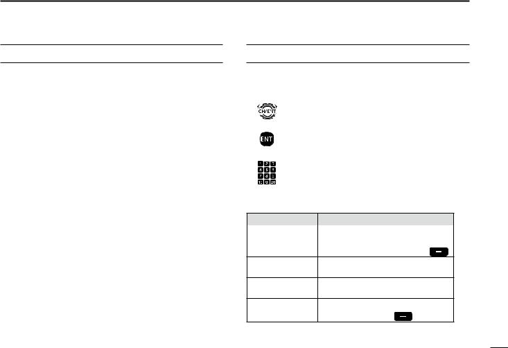
ACTION ICON DESCRIPTION
The following describes the [CH/ENT], [ENT] and the keypad operations in this instruction manual.
Rotate
: Rotate [CH/ENT] to select.
Push
: Push [ENT] to enter or set.
Push
: Push the keypad to enter a digit or text.
Also, you can use the following key functions in the Menu screen.
FUNCTION |
ACTION |
|
Select |
Rotate [CH/ENT]. |
|
|
Push [∫] or [√]. |
|
Enter |
Push [ENT], [CH/ENT], or [Enter] |
. |
Go to the next tree Push [ENT] or [≈]. level
Go back to the Push [CLR], [Ω], or [Back]  . previous tree level
Cancel |
Push [CLR]. |
|
Exit |
Push [MENU] or [Exit] |
. |
1
2
3
4
5
6
7
8
9
10
11
12
13
14
15
16
iv

TABLE OF CONTENTS
IMPORTANT...................................................................................... |
i |
|
EXPLICIT DEFINITIONS................................................................... |
i |
|
DISPOSAL......................................................................................... |
i |
|
IN CASE OF EMERGENCY.............................................................. |
ii |
|
INSTALLATION NOTE...................................................................... |
ii |
|
PRECAUTIONS................................................................................ |
iii |
|
COUNTRY CODE LIST.................................................................... |
iv |
|
ACTION ICON DESCRIPTION........................................................ |
iv |
|
1 |
OPERATING RULES................................................................... |
1 |
2 |
PANEL DESCRIPTION............................................................ |
2–8 |
|
■■ Front panel.............................................................................. |
2 |
|
■■ Software key function.............................................................. |
5 |
|
■■ Speaker Microphone............................................................... |
5 |
|
■■ Function display (Main screen)................................................ |
6 |
3 |
PREPARATION........................................................................... |
9 |
|
■■ Entering the MMSI code.......................................................... |
9 |
4 |
MENU SCREEN.................................................................. |
10–12 |
|
■■ Construction.......................................................................... |
10 |
|
■■ Selecting a Menu item........................................................... |
12 |
5 |
BASIC OPERATION............................................................ |
13–19 |
|
■■ Selecting a channel............................................................... |
13 |
|
■■ Setting the Call channel......................................................... |
14 |
|
■■ Receiving and transmitting.................................................... |
15 |
|
■■ Backlight function.................................................................. |
17 |
|
■■ Microphone Lock function...................................................... |
17 |
|
■■ Entering a Channel name...................................................... |
18 |
5 |
SCAN OPERATION............................................................. |
20–21 |
|
■■ Scan types............................................................................. |
20 |
|
■■ Favorite channels.................................................................. |
21 |
|
■■ Starting a scan....................................................................... |
21 |
6 |
DUALWATCH/TRI-WATCH....................................................... |
22 |
|
■■ Description............................................................................. |
22 |
|
■■ Operation............................................................................... |
22 |
7 |
DSC OPERATION............................................................... |
23–75 |
|
■■ DSC address ID..................................................................... |
23 |
|
■■ Entering the position and time............................................... |
25 |
|
■■ DSC Task mode..................................................................... |
27 |
|
■■ Sending a Distress call.......................................................... |
29 |
|
■■ Sending a Non-Distress call.................................................. |
42 |
|
■■ Receiving DSC calls.............................................................. |
54 |
|
■■ Received Call log................................................................... |
69 |
|
■■ Transmitted Call log............................................................... |
70 |
|
■■ DSC Settings......................................................................... |
71 |
8 |
MENU ITEMS...................................................................... |
76–81 |
|
■■ Menu items............................................................................ |
76 |
|
■■ Radio Settings....................................................................... |
77 |
|
■■ Configuration......................................................................... |
78 |
9 |
CONNECTIONS AND MAINTENANCE.............................. |
82–88 |
|
■■ Connections........................................................................... |
82 |
|
■■ Antenna................................................................................. |
84 |
|
■■ Fuse replacement.................................................................. |
84 |
|
■■ Cleaning................................................................................ |
84 |
|
■■ Supplied accessories............................................................. |
85 |
|
■■ Power source connections.................................................... |
86 |
|
■■ Mounting the transceiver....................................................... |
87 |
|
■■ Handset (HS-98).................................................................... |
88 |
10 |
SPECIFICATIONS AND OPTIONS..................................... |
89–90 |
|
■■ Specifications........................................................................ |
89 |
|
■■ Options.................................................................................. |
90 |
11 |
TROUBLESHOOTING........................................................ |
91–92 |
12 CHANNEL LIST......................................................................... |
93 |
|
13 |
DIGITAL INTERFACE (IEC 61162-1).................................. |
94–97 |
|
■■ I/O Sentences........................................................................ |
94 |
|
■■ Schematic diagram................................................................ |
97 |
|
■■ Hardware version.................................................................. |
97 |
|
■■ Software version.................................................................... |
97 |
INDEX..................................................................................... |
98–100 |
|
v

DDPriorities
•Read all rules and regulations pertaining to call priorities, and keep an up-to-date copy handy. Safety and distress calls take priority over all others.
•You must monitor Channel 16 when you are not operating on another channel.
•False or fraudulent distress calls are prohibited under law.
DDPrivacy
•Information overheard, but not intended for you, cannot lawfully be used in any way.
•Indecent or profane language is prohibited.
DDRadio licenses
(1) SHIP STATION LICENSE
You may require a current radio station license before using the transceiver. It is unlawful to operate a ship station which is not licensed, but required to be.
If required, contact your dealer or the appropriate government agency for a Ship-Radiotelephone license application. This government-issued license states the call sign which is your craft’s identification for radio purposes.
OPERATING RULES |
1 |
|
|
|
|
|
|||
|
|
|||
|
|
|||
|
|
|
|
|
(2) OPERATOR’S LICENSE |
|
1 |
||
|
2 |
|||
A Restricted Radiotelephone Operator Permit is the license |
||||
most often held by small vessel radio operators when a |
3 |
|||
radio is not required for safety purposes. |
|
|||
|
4 |
|||
If required, the Restricted Radiotelephone Operator Permit |
||||
5 |
||||
must be posted or kept with the operator. If required, only a |
||||
licensed radio operator may operate a transceiver. |
|
6 |
||
However, non-licensed individuals may talk over a |
|
7 |
||
transceiver if a licensed operator starts, supervises, ends |
8 |
|||
the call and makes the necessary log entries. |
|
9 |
||
|
|
|||
A current copy of the applicable government rules and |
|
10 |
||
regulations is only required to be on hand for vessels in |
11 |
|||
which a radio telephone is compulsory. However, even |
|
|||
if you are not required to have these on hand it is your |
|
12 |
||
responsibility to be thoroughly acquainted with all pertinent |
13 |
|||
rules and regulations. |
|
|||
|
|
14 |
||
|
|
15 |
||
|
|
16 |
||
1
 2 PANEL DESCRIPTION
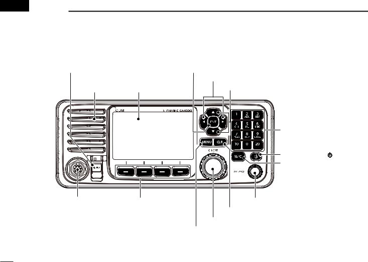
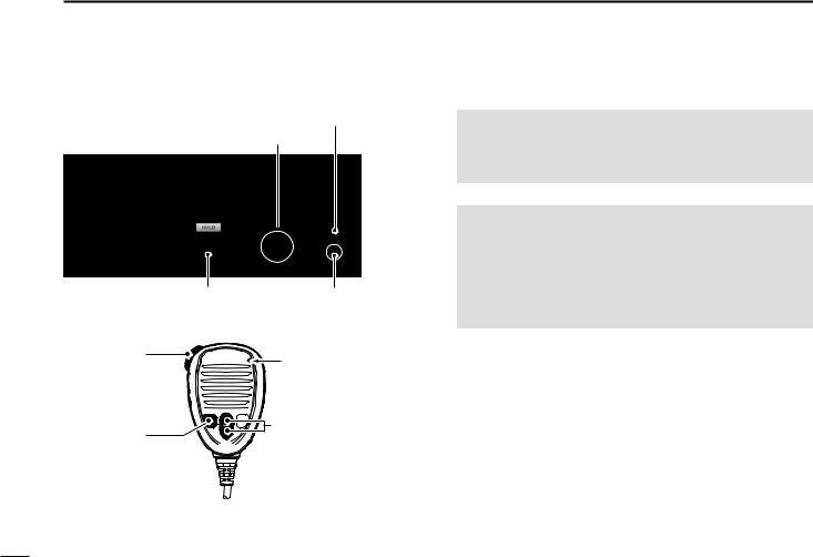
■■Front panel
q DISTRESS KEY [DISTRESS] |
w ENTER KEY [ENT] |
|
e LEFT AND RIGHT KEYS [Ω]/[≈] |
Speaker Function display (p. 6) |
r UP AND DOWN KEYS [∫]/[√] |
t KEYPAD |
y POWER KEY |
] |
u CHANNEL 16/ |
|
CALL CHANNEL KEY [16/C] |
|
MIC CONNECTOR |
!2SOFTWARE KEYS |
i VOLUME/SQUELCH DIAL [VOL/SQL] |
|
|
o CLEAR KEY [CLR] |
|
|
!0 CHANNEL SELECTOR/ENTER SWITCH [CH/ENT] |
|
|
!1 MENU KEY [MENU] |
2

q DISTRESS KEY [DISTRESS] (p. 29)
Hold down for 3 seconds to transmit a Distress call.
w ENTER KEY [ENT]
Push to set the entered data, selected item, and so on.
e LEFT AND RIGHT KEYS [Ω]/[≈]
Push to scroll the software key functions. (p. 5)
In the character or number entry mode, push to select the desired character or number in the keypad.
(p. 18)
r UP AND DOWN/CHANNEL SELECT KEYS [∫]/[√]
Push to select the operating channel (p. 13), Menu items (p. 12), Menu settings (p. 12), and so on.
While scanning, push to check the Favorite channels, change the scanning direction or manually resume a scan. (p. 21)
tKEYPAD
Push to enter numbers, letters or symbols. For channel number entry, see page 13. For channel name entry, see page 18.
y POWER KEY  ]
]
Hold down for 1 second to turn the transceiver ON or OFF.
PANEL DESCRIPTION 2
u CHANNEL 16/CALL CHANNEL KEY [16/C]
Push to select Channel 16. (p. 13)
Hold down for 1 second to select the Call channel. (p. 13)
•“CALL” is displayed when the Call channel is selected.
iVOLUME/SQUELCH DIAL [VOL/SQL] (p. 15)
Rotate to adjust the volume level.
Push once or twice to display the Volume or Squelch Setting screen, and then rotate to adjust the volume or squelch level.
o CLEAR KEY [CLR]
Push to cancel the entered data, or to return to the previous screen.
!0CHANNEL SELECTOR/ENTER SWITCH [CH/ENT]
Rotate to select the operating channel (p. 13), Menu items (p. 12), Menu settings (p. 12), and so on.
Push to set the entered data, selected item, and so on. (p. 12)
!1MENU KEY [MENU]
Push to enter or exit the Menu screen. (p. 12)
1
2
3
4
5
6
7
8
9
10
11
12
13
14
15
16
3

2 PANEL DESCRIPTION
■■ Front panel (Continued)
!2SOFTWARE KEYS (p. 5)
You can use various key functions that are assigned to the software keys, as described below.
Compose Distress* (p. 30)
Push to display the COMPOSE DISTRESS screen.
Compose Non-Distress* (p. 42)
Push to display the COMPOSE NON-DISTRESS screen.
Compose DROBOSE* (p. 36)
Push to display the COMPOSE DROBOSE screen.
Task Mode (p. 27)
When the transceiver has any task, push to enter the Task mode.
Scan (p. 21)
Push to start or stop a Normal or Priority scan.
Dualwatch/Tri-watch [DW] (p. 22)
Push to start or stop the Dualwatch or Tri-watch.
High/Low [HI/LO] (p. 15)
Push to set the output power level to high or low.
• Some channels are set to only low power.
Channel [CHAN] (p. 13)
When Channel 16 or the Call channel is selected, push to select the last selected channel.
Favorite channel [Favorite] (p. 21)
Push to set or clear the displayed channel as a Favorite channel.
Channel Name (p. 18)
Push to display the CHANNEL NAME screen.
Backlight (p. 17)
Push to open the Backlight Settings window.
DSC Log (p. 69)
Push to display the RCVD CALL LOG screen.
*These key functions are not displayed in the Radio Telephone (RT) mode. (p. 14)
4
■■Software key function
The transceiver has the software keys for various functions. The key function is displayed above the software key, as shown below.
DDSelecting the software key function
When “Ω” or “≈” is displayed beside the key icon, pushing [Ω] or [≈] scrolls the software key functions.
When you push [Ω] or [≈] once, 4 functions scroll together.
Push
Push |
Push this key to display the |
|
COMPOSE DISTRESS screen. |
|
Push |
Push |
|
PANEL DESCRIPTION 2
■■Speaker Microphone |
||
q PTT SWITCH |
Microphone |
|
[PTT] |
||
|
||
w UP/DOWN KEYS |
r CHANNEL 16/ |
|
[Y]/[Z] |
||
e TRANSMIT |
CALL CHANNEL KEY |
|
[16/C] |
||
POWER KEY |
||
|
||
[H/L] |
|
q PTT SWITCH [PTT] (pp. 15, 29)
Hold down to transmit, release to receive.
w UP/DOWN KEYS [Y]/[Z] (p. 21)
Push to select the Favorite channels, change scanning direction or manually resume a scan.
• When the “FAV on MIC” item is set to “OFF,” you can select all channels. (p. 78)
e TRANSMIT POWER KEY [H/L]
Push to set the power level to high or low. (p. 15)
• Some channels are set to only low power.
While holding down this key, turn ON the transceiver to turn the Microphone Lock function ON or OFF. (p. 17)
r CHANNEL 16/CALL CHANNEL KEY [16/C] (p. 13)
Push to select Channel 16.
Hold down for 1 second to select the Call channel.
• The “CALL” icon is displayed.
1
2
3
4
5
6
7
8
9
10
11
12
13
14
15
16
5
2 PANEL DESCRIPTION
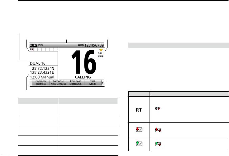
■■Function display (Main screen)
q Status area |
|
w Task area |
e Information area r Channel area |
y Position and Time area |
|
|
|
t Software key area |
|||
|
|
|
|
Display area |
|
Description |
|
q Status area |
Displays the current status. |
||
w Task area |
Displays up to 7 task icons. |
||
e Information area Displays various icons and the MMSI code.
r Channel area Displays the selected operating channel information. (p. 7)
t Software key area Displays the key function for each software key. (p. 5)
y Position and Time Displays the current position and |
|
area |
time. (p. 8) |
DDStatus area
The current status is displayed in the Status area.
Indicator |
Description |
SCAN 16 |
Displayed during a Priority scan. (p. 21) |
SCAN |
Displayed during a Normal scan. (p. 21) |
DUAL 16 |
Displayed during Dualwatch. (p. 22) |
TRI 16 |
Displayed during Tri-watch. (p. 22) |
DDTask area
Up to 7 task icons are displayed in the Task area when the transceiver has a task.
Indicator |
Description |
Displayed while in the Radio Telephone (RT) mode. (p. 14)
•“ ” is displayed when the RT mode task is activated.
•Disappears if no operation occurs during the preset period of time. (p. 80)
Displayed after receiving a DSC call. (p. 27)
• “ ” is displayed when the RX call task is activated.
Displayed after making a DSC call. (p. 27)
• “ ” is displayed when the TX call task is activated.
6
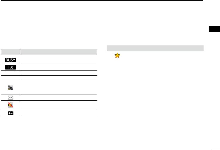
DDInformation area
The 9 digit MMSI (Maritime Mobile Service Identity: DSC self ID) code and the following indicators are displayed in the Information area.
Indicator |
Description |
Displayed when receiving a signal or when the squelch is open.
Displayed while transmitting.
25W Displayed when high power is selected.
1W Displayed when low power is selected.
Displayed when the transceiver receives a valid GPS data from the GPS receiver.
Blinks while invalid GPS data is being received.
Blinks when there is an unread DSC message.
Displayed when the “Internal Speaker” item is OFF. (p. 81)
Displayed when the battery voltage is low.
PANEL DESCRIPTION 2
DDChannel area
The selected operating channel number, channel name, and the following indicators are displayed in the Channel area.
Indicator |
Description |
|
Displayed when a Favorite (Tag) channel is |
|
selected. |
CALL |
Displayed when the Call channel is selected. |
DUP |
Displayed when a Duplex channel is selected. |
1
2
3
4
5
6
7
8
9
10
11
12
13
14
15
16
7

2 PANEL DESCRIPTION
■ Function display (Main screen) (Continued)
DDPosition and Time area
POSITION AREA
The current position is displayed when valid GPS data is received, or you manually enter your position.
Indicator |
Description |
NO POSITION Displayed when a GPS receiver is not |
|
|
connected and your position has not been |
|
manually entered. |
??Blinks every 2 seconds instead of your position when the GPS position is invalid.
•The last position is held for only 23.5 hours. After that, “NO POSITION” will be displayed.
Blinks every 2 seconds instead of the position after 4 hours have passed since you manually entered your position.
•The manually entered position is held for only 23.5 hours. After that, “NO POSITION” will be displayed.
TIME AREA
The current time is displayed when a valid GPS data is received, or manually enter the time.
The date information is displayed when the RMC GPS sentence formats are included in the GPS signal.
Indicator |
Description |
NO TIME |
Displayed when a GPS receiver is not |
|
connected and the time has not been |
|
manually entered. |
Local |
Displayed when the offset time is set. |
Manual |
Displayed when the time was manually entered. |
UTC |
Displayed when the GGA, GLL or GNS GPS |
|
sentence formats are included in the GPS |
|
signal. |
??Blinks every 2 seconds instead of the time when the GPS current time is invalid.
•After 23.5 hours has passed, “NO TIME” will be displayed.
Blinks every 2 seconds instead of the time after 4 hours have passed since you manually entered the time.
•The manually entered time is held for only 23.5 hours. After that, “NO TIME” will be displayed.
8

|
3 |
|
PREPARATION |
|
|
|
||
|
■■Entering the MMSI code
First, you must enter the 9 digit MMSI (Maritime Mobile Service Identity: DSC self ID) code at power ON.
You can perform this initial code entry ONLY ONCE. After entry, only your dealer or distributor can change it. If you have already entered your MMSI code, these procedures are not necessary.
qqHold down  ] for 1 second to turn ON the transceiver.
•Three short beeps sound.
•“Push [ENT] to Register Your MMSI” is displayed.
wwPush [ENT] to enter the MMSI code entry mode.
Push
eeEnter your 9 digit MMSI code.
Push
+
Rotate
rrAfter entering the 9th digit, set the ID.
Push
ttReenter your MMSI code to confirm.
Push
Rotate
yyAfter entering the 9th digit, register the ID.
Push
•When you successfully enter your MMSI code, the following screen is displayed.
•After that, the Main screen is displayed. The registered MMSI code is displayed at the top of the screen.
1
2
3
4
5
6
7
8
9
10
11
12
13
14
15
16
•Push [CLR] to cancel the entry. In that case, the transceiver displays “Push
[ENT] to Register Your MMSI” again. |
9 |
|
 4 MENU SCREEN
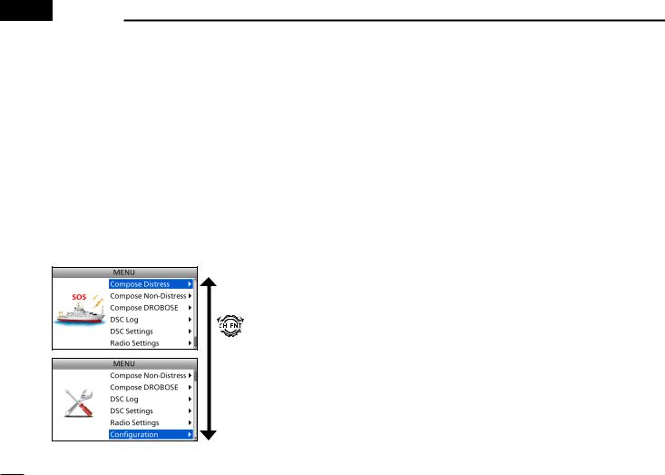
You can use the Menu screen to set infrequently changed values or function settings.
■■Construction
The Menu screen is constructed in a tree structure.
You can go to the next tree level with [ENT], or go back a level with [CLR]. See page iv for details.
To select an item, rotate [CH/ENT].
Rotate
• Compose Distress (p. 30)
Nature of Distress |
Select a Nature of Distress |
|
option. |
Position |
Enter your position. |
• Latitude |
Displays latitude data. |
• Longitude |
Displays longitude data. |
• UTC |
Displays UTC offset data. |
• Compose Non-Distress (p. 42) |
|
Message Type |
Select a Message Type |
|
option. |
Address |
Enter a destination address. |
Position*1 |
Enter your position. |
• Latitude*1 |
Displays latitude data. |
• Longitude*1 |
Displays longitude data. |
• UTC*1 |
Displays UTC offset data. |
Category |
Select a Category option. |
Mode*1 |
Select a Mode option. |
Channel*1 |
Select an Intership channel. |
• Compose DROBOSE (p. 36) |
|
Message Type |
Select a Message Type |
|
option. |
Address*1 |
Enter a destination address. |
Distress ID |
Enter a Distress ID. |
Nature of Distress |
Select a Nature of Distress |
|
option. |
Position |
Enter your position. |
• Latitude |
Displays latitude data. |
• Longitude |
Displays longitude data. |
• UTC |
Displays UTC offset data. |
Mode |
Displays the |
|
communication mode. |
*1 These items may not be displayed, depending on the “Message Type” itemʼs option.
*2 This item is not displayed, when a valid GPS data is received.
10
• DSC Log (pp. 69, 70)
Received Call Log |
|
• Distress |
Displays the received |
|
Distress call log. |
• Others |
Displays the received call log |
|
other than the Distress call. |
Transmitted Call Log |
Displays the transmitted |
|
call log. |
• DSC Settings (p. 71) |
|
Position Input*2 |
Enter your position. |
Individual ID |
Enter an Individual ID. |
Group ID |
Enter a Group ID. |
Individual ACK |
Select an Individual ACK |
|
option. |
Position ACK |
Select a Position ACK |
|
option. |
Polling ACK |
Select a Polling ACK option. |
Test ACK |
Select a Test ACK option. |
Medical |
Turn the Medical |
Transports |
Transports call ON or OFF. |
Ships and Aircraft |
Turn the Ships and Aircraft |
|
call ON or OFF. |
10 Second Delay |
Turn the 10 Second Delay |
|
function ON or OFF. |
Alarm Status |
|
• Safety |
Turn the Alarm Status for |
|
Safety ON or OFF. |
• Routine |
Turn the Alarm Status for |
|
Routine ON or OFF. |
• Warning |
Turn the Alarm Status for |
|
Warning ON or OFF. |
• Self-Terminate |
Turn the Alarm Status for |
|
Self-Terminate ON or OFF. |
• Discrete |
Turn the Alarm Status for |
|
Discrete ON or OFF. |

• DSC Settings (Continued)
CH70 SQL Level |
Select the Channel 70 |
|
squelch level. |
Auto Print |
Turn the Auto Print function |
|
ON or OFF. |
DSC Loop Test |
Starts the DSC Loop Test. |
• Radio Settings (p. 77) |
|
Scan Type |
Select a Scan Type from |
|
Normal Scan or Priority |
|
Scan |
Scan Timer |
Turn the Scan Timer |
|
function ON or OFF. |
Dual/Tri-Watch |
Select the Dualwatch or |
|
Tri-watch function. |
Call Channel |
Set the Call channel. |
FAV on MIC |
Turn the FAV on MIC |
|
function ON or OFF. |
FAV Settings |
Set the Favorite channel |
|
settings. |
• Configuration (p. 78)
Key Beep |
Turn the Key Beep function |
|
ON or OFF. |
UTC Offset |
Set the UTC Offset. |
Inactivity Timer |
Set the inactivity timer. |
• Not DSC |
Set the inactivity timer for |
Related |
not DSC related calls. |
• DSC Related |
Set the inactivity timer for |
|
DSC related calls. |
• Distress |
Set the inactivity timer for |
Related |
Distress related calls. |
• RT Related |
Set the inactivity timer |
|
for the Radio Telephone |
|
mode. |
NMEA Data |
Set the NMEA 0183 Output |
Output |
functions. |
• DSC Data |
Select a DSC Data Output |
Output |
option. |
• POS Data |
Select a Position Data |
Output |
Output option. |
Internal Speaker |
Turn the Internal Speaker |
|
function ON or OFF. |
MIC Type |
Select a microphone type. |
Software Version |
Display the software |
|
version. |
MENU SCREEN 4
1
2
3
4
5
6
7
8
9
10
11
12
13
14
15
16
11

4 MENU SCREEN
■■Selecting a Menu item
Follow the procedures as described below to select a Menu item.
Example: Set the Tri-watch function. qqPush [MENU] to display the MENU
screen.
wwRotate [CH/ENT] to select
“Radio Settings,” then push [ENT].
rrRotate [CH/ENT] to select “Tri-Watch,” then push [ENT].
Rotate
+
Push
Rotate
+
Push
eeRotate [CH/ENT] to select “Dual/Tri-Watch,” then push [ENT].
Rotate
+
Push
•Sets the Tri-watch function, and then goes back to the RADIO SETTINGS screen, after pushing [ENT].
ttPush [MENU] to return to the Main screen.
12
|
5 |
|
BASIC OPERATION |
|
|
|
||
|
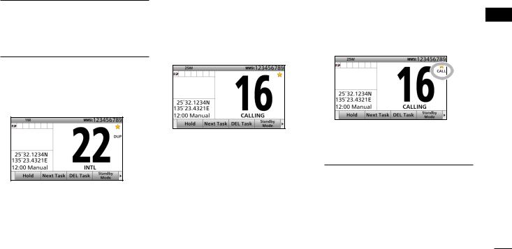
■■Selecting a channel
DDSelecting a regular channel
Selecting a channel in sequence:
Rotate [CH/ENT].Push [∫] or [√].
Entering the desired channel number:
Push the keypad to directly enter the desired channel number.
Example: Selecting Channel 22 Push [2 abc] → [2 abc].
DDSelecting Channel 16
Channel 16 is the distress and safety channel. It is used for establishing initial contact with a station, and for emergency communications.
While standing by, you must monitor Channel 16.
Push [16/C].
DDSelecting Call channel
You have a leisure use Call channel for quick recall.
To set your most used channel, see page 14.
The default Call channel is Channel 16.
Hold down [16/C] for 1 second.
To recall the channel that was displayed before selecting Channel 16:
Push [CHAN]  .
.
To recall the channel that was displayed before selecting Call channel:
Push [CHAN]  .
.
1
2
3
4
5
6
7
8
9
10
11
12
13
14
15
16
13
5 BASIC OPERATION
■■ Selecting a channel (Continued)
TIP: After receiving a signal or you operate the transceiver, the transceiver enters the Radio Telephone (RT) mode. In the RT mode, you can make a voice communication except for the DSC operation.
•“ ” is displayed while in the RT mode.
•“ ” is displayed when the RT mode task is activated.
•“ ” or “
 ” disappears if no operation occurs during the preset period of time. (p. 80)
•The following software key functions are not displayed in the RT mode. [Compose Distress]
[Compose Non-Distress] [Compose DROBOSE]
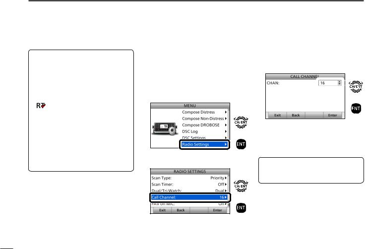
■■Setting the Call channel
You can set the Call channel with your most often-used channel for quick recall.
qqPush [MENU] to display the MENU screen.
wwRotate [CH/ENT] to select
“Radio Settings,” then push [ENT].
Rotate
+
Push
eeRotate [CH/ENT] to select
“Call Channel,” then push [ENT].
Rotate
+
Push
rrRotate [CH/ENT] to select the desired channel to be set as the Call channel, then push [ENT].
 Rotate
+
Push
•Goes back to the previous screen, after pushing [ENT].
ttPush [MENU] to return to the Main screen.
TIP: To confirm that your setting is correctly set, hold down [16/C] for 1 second. (p. 13)
14
■■Receiving and transmitting
CAUTION: Transmitting without an antenna will damage the transceiver.
qqFirst, turn ON the PS-310 dc-dc
power supply.
wwHold down [ ] for 1 second to turn ON the transceiver.
•If no MMSI code is entered, “Push [ENT] to Register Your MMSI” is displayed.
(p. 9)
eeRotate [VOL/SQL] to adjust the audio level.
rrPush [VOL/SQL] once or twice to open the SQL Setting window.
ttRotate [VOL/SQL] to adjust the squelch level until the noise just disappears.
yySelect a channel. (p. 13) uuPush [Ω] or [≈] until software key
function [HI/LO] is displayed. iiPush [HI/LO]  to select an
output power high or low.
Push
ooHold down [PTT], and speak at your normal voice level.
• “ ” is displayed.
!0Release [PTT] to return to receive.
BASIC OPERATION 5
NOTE:
Selecting a channel:
•When receiving a signal, “ ” is displayed.
• You can use Channel 70 only for Digital Selective Calling (DSC) transmissions.
•When the “FAV on MIC” item is set to “OFF,” you can select all channels using the [∫] or [√] keys on the microphone. (p. 78)
Selecting an output power:
•“25W” is displayed when high power is selected. Choose high power for longer distance communications.
•“1W” is displayed when low power is selected. Choose low power for short range communications.
•Some channels are restricted to low power.
1
2
3
4
5
6
7
8
9
10
11
12
13
14
15
16
15
5 BASIC OPERATION
■■ Receiving and transmitting (Continued)
wwTurn ON the transceiver yySelect a channel
iiSelect an output power |
eeSet the audio level |
|
(You should first select the |
rrSet the squelch level |
|
“HI/LO” key function.) |
|
|
ooTransmit |
Microphone |
|
!0Receive |
||
|
iiSelect an |
yySelect a channel |
|
|
output power |
|
IMPORTANT: To maximize the readability of your transmitted signal at a receiver station, pause a second after pushing [PTT], and then hold the microphone 5 to 10 cm from your mouth and speak at your normal voice level.
NOTE for the Time-out Timer (TOT) function
The TOT function inhibits continuous transmission beyond a preset time period after the transmission starts.
10 seconds before transmission is cut off, a beep sounds to indicate the transmission will be cut off, and “TOT” is displayed in the channel name field. You cannot transmit again for 10 seconds after it is cut off.
16
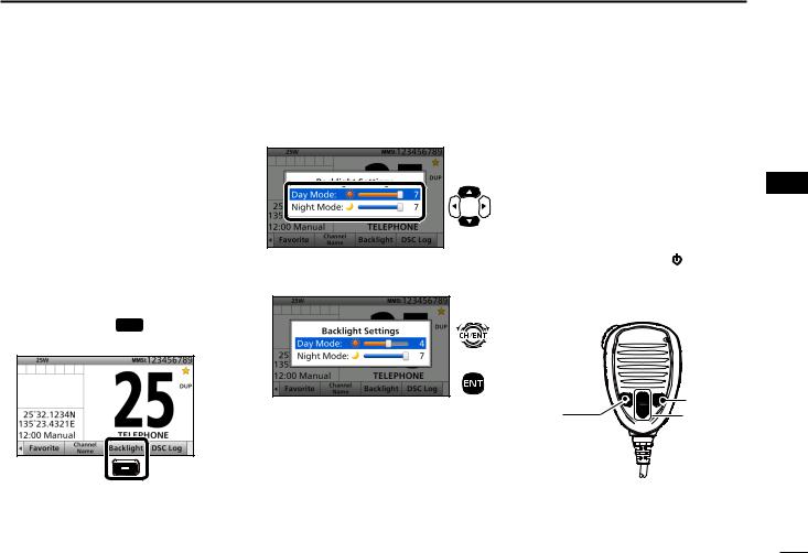
■■Backlight function
The function display and keys can be backlit for better visibility under low light conditions.
And, you can set the Backlight mode to Day mode or Night mode.
The Day mode is for the daytime operation, and the screen items are in color.
The Night mode is for the nighttime operation, and the screen items are in black and red.
qqPush [Ω] or [≈] until software key function [Backlight] is displayed. wwPush [Backlight]  to open the
Backlight Settings window.
Push
•In the Backlight Setting screen, if you push no key for about 5 seconds, the transceiver automatically returns to the
Normal operation mode.
eePush [∫] or [√] to select “Day Mode” or “Night Mode.”
Push
rrRotate [CH/ENT] to adjust the backlight level, then push [ENT].
Rotate
+
Push
•The backlight level is adjustable in 7 levels and “OFF.”*
*“OFF” is selectable only for the Day mode.
BASIC OPERATION 5
■■Microphone Lock |
1 |
||
function |
|
2 |
|
The Microphone Lock function |
3 |
||
4 |
|||
electrically locks [∫], [√], [16/C] and |
|||
[H/L] on the supplied microphone. |
5 |
||
This prevents accidental channel |
|||
6 |
|||
changes and function access. |
|||
While holding down [H/L] on the |
7 |
||
8 |
|||
microphone, hold down [ |
] for 1 |
||
second to turn ON the transceiver. |
9 |
||
• The Microphone Lock function is turned |
|||
ON or OFF. |
|
10 |
|
|
|
||
|
|
11 |
|
|
|
12 |
|
|
[16/C] |
13 |
|
[H/L] |
14 |
||
[∫], [√] |
|||
|
|
15 |
|
|
|
16 |
|
17
5 BASIC OPERATION
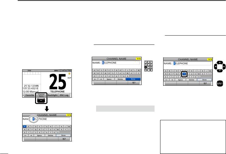
■■Entering a Channel name
You can rename each channel with a unique alphanumeric ID of up to 10 characters.
qqFirst, cancel the Dualwatch, Tri-watch or Scan function, if activated.
wwRotate [CH/ENT] to select a channel. eePush [Channel Name]  .
.
Push
rrEnter the desired character.
Using the keypad:
Push a keypad to enter a character. (Example: Entering “S”)
Push
5 times
•To move the cursor, rotate [CH/ENT].
•You can enter the following characters by pushing the keypad one or more times.
KEY |
|
ENTRY |
KEY |
|
ENTRY |
[1] |
1 |
|
[6] |
6 M N O |
|
[2] |
2 A B C |
[7] |
7 |
P Q R S |
|
[3] |
3 |
D E F |
[8] |
8 T U V |
|
[4] |
4 |
G H I |
[9] |
9 |
W X Y Z |
[5] |
5 |
J K L |
[0] |
0 |
. (period) |
Using [Y], [Z], [Ω], or [≈]:
Push [Y], [Z], [Ω], or [≈] to select the desired character. Then, push [ENT] to enter the character.
(Example: Entering “S”)
Push
+
Push
•To move the cursor, push [Y], [Z], [Ω], or [≈] to select either arrow, “←” or “→,” then push [ENT].
•You can enter capital letters, 0 to 9, some symbols (! " # $ % & ' ( ) * + , – . / [ \ ] ^ _ : ; < = > ?) and a space.
See ʽCommon operationʼ as described on page 19 for details of the
following operations.
•Entering a symbol/space
•Deleting a character
•Canceling an entry
•Correcting an entry
18

Common operation
•To enter a symbol:
Push [“!$?”]  , then push [Y], [Z], [Ω], or [≈] to select the desired character. And then, push [ENT].
•To enter a space:
Push [Y], [Z], [Ω], or [≈] to select a “Space,” and then push [ENT].
•To delete a character:
Push [Y], [Z], [Ω], or [≈] to select “Delete,” and then push [ENT].
•To cancel an entry:
Push [CLR].
•To correct an entry:
Move the cursor to the character, and then, enter the correct character.
ttRepeat step r to enter all characters.
yyPush [Y], [Z], [Ω], or [≈] to select “Done,” then push [ENT].
•Return to the previous screen.
•During the keypad operation, “Done” is automatically selected.
BASIC OPERATION 5
1
2
3
4
5
6
7
8
9
10
11
12
13
14
15
16
19
 6 SCAN OPERATION
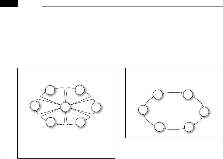
■■Scan types
You can find ongoing calls by scanning the Favorite channels without rotating [CH/ENT].
The GM600 has two scan types.
•Priority scan (default)
•Normal scan
PRIORITY SCAN
A Priority scan sequentially scans all Favorite channels while also monitoring Channel 16.
|
CH 01 |
CH 02 |
CH 06 |
CH 16 |
CH 03 |
|
||
|
CH 05 |
CH 04 |
When a signal is received:
• On Channel 16
The scan pauses until the signal on Channel 16 disappears.
• On a channel other than Channel 16:
The scan switches to Dualwatch, until the signal disappears.
Before you start a scan:
•Set the desired channels you want to scan as Favorite channels. (Scans only Favorite channels.) (p. 21)
•Set the desired scan type to “Normal" or “Priority.” (p. 77)
NORMAL SCAN
A Normal scan sequentially scans all Favorite channels. However, the scan does not check Channel 16 unless it is set as a Favorite channel.
CH 01 |
CH 02 |
CH 06 |
CH 03 |
|
|
CH 05 |
CH 04 |
20
■■Favorite channels
You can quickly recall often-used channels by setting them as Favorite channels.
All channels are set as Favorite channels by default.
DDSetting
qqRotate [CH/ENT] to select a channel.
wwPush [Favorite]  to set the channel as a Favorite channel.
• “ ” is displayed.
DDSelecting
Push [∫] or [√] on the microphone.
• Non-Favorite channels are skipped and not displayed. • When the “FAV on MIC” item is set to “OFF,” you can select all channels. (p. 78)
TIP: You can select all channels by rotating [CH/ENT] or pushing [∫] or [√] on the transceiver. (p. 13)
DDClearing
qqSelect a Favorite channel to clear.
wwPush [Favorite]  to clear the channel as the Favorite channel.
• “ ” disappears.
TIP: You can clear all Favorite channels in the Menu screen. (p. 78)
SCAN OPERATION 6
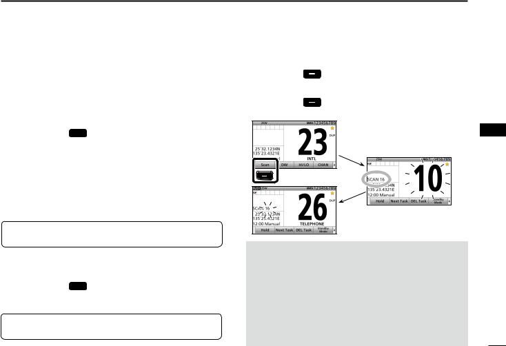
■■Starting a scan
qqPush [Scan] |
to start a scan. |
•During a Priority scan, “SCAN 16” is displayed. During a Normal scan, “SCAN” is displayed.
wwPush [Scan] |
again to cancel the scan. |
• “SCAN 16” or “SCAN” disappears.
Example:
Starting a priority scan.
Scanning starts
Push
When a signal is received
NOTE:
•When a signal is received, the scan pauses until the signal disappears, or resumes after pausing for 5 seconds, depending on the “Scan Timer” setting. (p. 77)
•You can check the scanning channel, change the scan direction, or manually resume the scan by pushing [∫] or [√] on either the transceiver or the microphone.
•A beep tone sounds and “16” blinks when a signal is received on Channel 16 during a Priority scan.
•In order to properly receive signals, you must adjust the squelch to the proper level. (p. 15)
1
2
3
4
5
6
7
8
9
10
11
12
13
14
15
16
21
 7 DUALWATCH/TRI-WATCH
■■Description
Dualwatch and Tri-watch are convenient to monitor Channel 16 while you are listening or talking on another channel.
|
|
|
|
CH 88 |
CH 16 |
CH 88 |
Call |
CH 9 |
CH 16 |
|
|
|||
|
|
channel |
|
|
Monitors Channel 16 while listening or talking on another channel (example: CH 88).
Dualwatch
Monitors Channel 16 and
the Call channel while listening or talking on another channel (example: CH 88).
Tri-watch
When a signal is received:
• On Channel 16
Dualwatch/Tri-watch pauses on Channel 16 until the signal disappears.
• On the Call channel
Tri-watch switches to Dualwatch until the signal on the Call channel disappears.
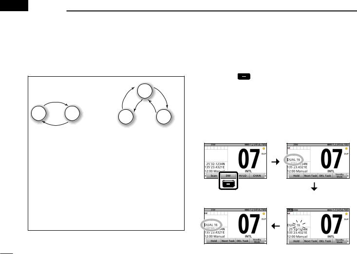
■■Operation
qqSelect Dualwatch or Tri-watch in the Menu screen. (p. 77) wwSelect a channel. (p. 13)
eePush [DW] to start Dualwatch or Tri-watch.
•During Dualwatch, “DUAL 16” is displayed. During Tri-watch, “TRI 16” is displayed.
•Abeep tone sounds and “16” starts to blink when a signal is received on Channel 16.
rrPush [DW] again to cancel Dualwatch or Tri-watch.
Example: Operating Dualwatch on Channel 07.
Dualwatch starts.
Push |
|
Dualwatch resumes after |
When a signal is received on |
the signal disappears. |
the Channel 16. |
22
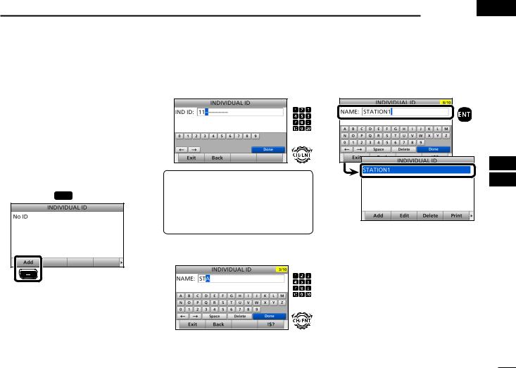
■■DSC address ID
You can enter a total of 100 DSC address IDs (Individual ID: 75, Group
ID: 25), and assign a name of up to 10 characters.
DDEntering Individual ID qqPush [MENU].
wwSelect “Individual ID,” then push [ENT].
(DSC Settings > Individual ID) eePush [Add]  .
.
Push
DSC OPERATION 8 
rrEnter a 9 digit Individual ID.
Push
+
Rotate
TIP: You must set the first digit for the Individual ID to between ʻ1ʼ and ʻ9.ʼ
•The first digit must be set to ‘0’ for a
Group ID.
•The first two digits must be set to ‘0’ for any Coast station ID.
ttAfter entering all 9 digits, push [ENT]. yyEnter the desired ID name.
Push
+
Rotate
uuAfter entering, push [ENT].
Push
•The entered Individual ID and name are added to the ID list.
iiPush [MENU] to return to the Main screen.
1
2
3
4
5
6
7
8
9
10
11
12
13
14
15
16
• See page 18 for text entry details.
23

8 DSC OPERATION
DDEntering Group ID qqPush [MENU].
wwSelect “Group ID,” then push [ENT]. (DSC Settings > Group ID)
eePush [Add]  .
.
Push
rrEnter a 9 digit Group ID.
Push
+
Rotate
TIP: You must set the first digit for a
Group ID to ‘0.’
•The first digit must be set to between ‘1’ and ‘9’ for an Individual ID.
•The first two digits must be set to ‘0’ for any Coast station ID.
24
ttAfter entering all 9 digits, push [ENT]. yyEnter the desired ID name.
Push
Rotate
• See page 18 for text entry details. uuAfter entering, push [ENT].
Push
DDDeleting an entered ID qqPush [MENU].
wwSelect “Individual ID” or “Group ID,” then push [ENT].
(DSC Settings > Individual ID) (DSC Settings > Group ID)
eeRotate [CH/ENT] to select the ID to delete.
rrPush [Delete]  .
.
Push
ttPush [OK]  .
.
•The entered Group ID and name are added to the ID list.
iiPush [MENU] to return to the Main screen.
Push
•After deleting, returns to the ID list screen. yyPush [MENU] to return to the Main
screen.
 Loading...