


 Loading...
INSTRUCTION MANUAL
HF/VHF/UHF ALL MODE TRANSCEIVER
i7100
This device complies with Part 15 of the FCC Rules. Operation is subject to the following two conditions: (1) this device may not cause harmful interference, and (2) this device must accept any interference received, including interference that may cause undesired operation.
WARNING: MODIFICATION OF THIS DEVICE TO RECEIVE CELLULAR RADIOTELEPHONE SERVICE SIGNALS IS PROHIBITED UNDER FCC RULES AND FEDERAL LAW.

FOREWORD
Thank you for purchasing this fine Icom product. The IC-7100 hf/vhf/uhf all mode transceiver is designed and build with Icom’s superior technology and craftsmanship combining traditional analog technologies with the new digital technology, Digital Smart Technologies for Amateur Radio (D-STAR), for a balanced package. With proper care, this product should provide you with years of trouble-free operation.
We thank you for making your IC-7100 your radio of choice, and hope you agree with Icom’s philosophy of “technology first.” Many hours or research and development went into the design of your IC-7100.
FEATURES
IF DSP features
All mode capability covering 160–2 m and 70 cm (depending on version)
Compact with separated front panel
±0.5 ppm of high frequency stability
Baudot RTTY demodulator
Selectable SSB transmission passband width (For both higher and lower pass frequency)
Standard voice synthesizer/voice recorder
SD card slot ready for several memory storage
Voice recorder to records your communication
DV mode (Digital voice + Low-speed data communication) operation-ready
–Text message and call sign exchange
–Transmit position data
DR (D-STAR Repeater) mode and repeater list allow you to easily operate using a D-STAR repeater
Spurious signals may be received near some frequencies.
These are created in the internal circuit and does not indicate a transceiver malfunction.
Icom, Icom Inc. and the Icom logo are registered trademarks of Icom Incorporated (Japan) in Japan, the United States, the United Kingdom, Germany, France, Spain, Russia and/ or other countries.
“AI” means “Advanced Instructions.” “sec. MM” means section number.
So when “(AI sec. MM)” is described on this manual, see the PDF type Advanced Instruction’s section number for your reference.
EXPLICIT DEFINITIONS
WORD |
DEFINITION |
|
R DANGER! |
Personal death, serious injury or an ex- |
|
plosion may occur. |
||
|
||
|
|
|
R WARNING! |
Personal injury, fire hazard or electric |
|
shock may occur. |
||
|
|
|
CAUTION |
Equipment damage may occur. |
|
|
|
|
NOTE |
Recommended for optimum use. No risk |
|
of personal injury, fire or electric shock. |
||
|
||
|
|
IMPORTANT
READ ALL INSTRUCTIONS carefully and completely before using the transceiver.
SAVE THIS INSTRUCTION MANUAL— This instruction manual contains important operating instructions for the IC-7100.
FCC INFORMATION
• FOR CLASS B UNINTENTIONAL RADIATORS:
This equipment has been tested and found to comply with the limits for a Class B digital device, pursuant to part 15 of the FCC Rules. These limits are designed to provide reasonable protection against harmful interference in a residential installation. This equipment generates, uses and can radiate radio frequency energy and, if not installed and used in accordance with the instructions, may cause harmful interference to radio communications. However, there is no guarantee that interference will not occur in a particular installation. If this equipment does cause harmful interference to radio or television reception, which can be determined by turning the equipment off and on, the user is encouraged to try to correct the interference by one or more of the following measures:
•Reorient or relocate the receiving antenna.
•Increase the separation between the equipment and receiver.
•Connect the equipment into an outlet on a circuit different from that to which the receiver is connected.
•Consult the dealer or an experienced radio/TV technician for help.
CAUTION: Changes or modifications to this device, not expressly approved by Icom Inc., could void your authority to operate this device under FCC regulations.
i

PRECAUTIONS
R DANGER HIGH VOLTAGE! NEVER touch an antenna or internal antenna connector during transmission. This may result in an electrical shock or burn.
R WARNING RF EXPOSURE! This device emits Radio Frequency (RF) energy. Extreme caution should be observed when operating this device. If you have any questions regarding RF exposure and safety standards please refer to the Federal Communications Commission Office of Engineering and Technology’s report on Evaluating Compliance with FCC Guidelines for Human Radio Frequency Electromagnetic Fields (OET Bulletin 65).
R WARNING! NEVER operate the transceiver while driving a vehicle. Safe driving requires your full attention— anything less may result in an accident.
R WARNING! NEVER operate the transceiver with an earphone, headphones or other audio accessories at high volume levels. Hearing experts advise against continuous high volume operation. If you experience a ringing in your ears, reduce the volume level or discontinue use.
R WARNING! NEVER apply AC power to the [DC13.8V] connector on the transceiver rear panel. This could cause a fire or damage the transceiver.
R WARNING! NEVER apply more than 16 V DC to the [DC13.8V] connector on the transceiver rear panel or use reverse polarity. This could cause a fire or damage the transceiver.
R WARNING! NEVER cut the DC power cable between the DC plug and fuse holder. If an incorrect connection is made after cutting, the transceiver might be damaged.
R WARNING! NEVER let metal, wire or other objects touch any internal part or connectors on the rear panel of the transceiver. This may result in an electric shock or this could cause a fire or damage the transceiver.
R WARNING! NEVER operate or touch the transceiver with wet hands. This may result in an electric shock or may damage the transceiver.
R WARNING! Immediately turn the transceiver power OFF and remove the power cable if it emits an abnormal odor, sound or smoke. Contact your Icom dealer or distributor for advice.
CAUTION: NEVER expose the transceiver to rain, snow or any liquids.
CAUTION: NEVER change the internal settings of the transceiver. This may reduce transceiver performance and/or damage to the transceiver.
DO NOT operate the transceiver near unshielded electrical blasting caps or in an explosive atmosphere.
DO NOT use harsh solvents such as benzine or alcohol to clean the transceiver, as they will damage the transceiver’s surfaces. If the transceiver becomes dusty or dirty, wipe it clean with a soft, dry cloth.
DO NOT use or place the transceiver in areas with temperatures below –10°C (+14°F) or above +60°C (+140°F). Be aware that temperatures on a vehicle’s dashboard can exceed +80°C (+176°F), resulting in permanent damage to the transceiver if left there for extended periods.
DO NOT place the transceiver in excessively dusty environments or in direct sunlight.
DO NOT place the transceiver against walls or putting anything on top of the transceiver. This will obstruct heat dissipation.
Place the transceiver in a secure place to avoid inadvertent use by children.
During mobile operation, NEVER place the transceiver where air bag deployment may be obstructed.
During mobile operation, DO NOT place the transceiver where hot or cold air blows directly onto it.
During mobile operation, DO NOT operate the transceiver without running the vehicle’s engine. When the transceiver’s power is ON and your vehicle’s engine is OFF, the vehicle’s battery will soon become exhausted.
Make sure the transceiver power is OFF before starting the vehicle engine. This will avoid possible damage to the transceiver by ignition voltage spikes.
During maritime mobile operation, keep the transceiver and microphone as far away as possible from the magnetic navigation compass to prevent erroneous indications.
BE CAREFUL! The rear panel will become hot when operating the transceiver continuously for long periods of time.
BE CAREFUL! If a linear amplifier is connected, set the transceiver’s RF output power to less than the linear amplifier’s maximum input level, otherwise, the linear amplifier will be damaged.
Use Icom microphones only (supplied or optional). Other manufacturer’s microphones have different pin assignments, and connection to the IC-7100 may damage the transceiver.
ii
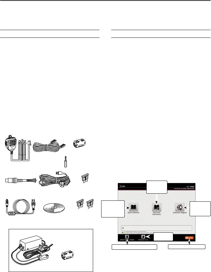
SUPPLIED ACCESSORIES
The following accessories are supplied with the transceiver.
q Hand microphone ............................................... |
1 |
w Control cable....................................................... |
1 |
e Ferrite EMI filter.................................................... |
1 |
For European versions................ |
2 |
r 3.5 (d) mm plug.................................................... |
1 |
t ACC cable............................................................. |
1 |
y DC power cable* (OPC-1457) ............................ |
1 |
or (OPC-2095) ............................ |
1 |
u Spare fuse (ATC 5 A) .......................................... |
1 |
i USB cable............................................................. |
1 |
o CD........................................................................ |
1 |
!0Spare fuse (ATC 30 A) ........................................ |
2 |
* Depending on the version.
q
w e
|
r |
|
y |
u |
|
t |
|
|
i |
!0 |
|
o |
||
|
For European versions
y
e
(See p. 2-7 for installation details)
ABOUT THE SUPPLIED CD
The following instructions and installers are included on the CD.
•Basic instructions
Instructions for the basic operations, the same as this manual
•Advanced Instructions
Instructions for the advanced operations and more details are described than in this manual
•Schematic diagram
Includes the schematic and block diagrams
•HAM radio Terms
A glossary of HAM radio terms
•Adobe® Reader® Installer
Installer for Adobe® Reader®
DDStarting the CD
qqInsert the CD into the CD drive.
•Double click “Autorun.exe” on the CD.
•Depending on the PC setting, the Menu screen shown below is automatically displayed.
wwClick the desired button to open the file.
• To close the Menu screen, click [Quit].
Opens the
Advanced
Instructions
Opens the |
|
|
|
|
Opens the |
|
|
|
|
||
Basic |
|
|
|
|
|
|
|
|
|
Schematic |
|
Instructions |
|
|
|
|
|
|
|
|
|
diagram |
|
(this manual) |
|
|
|
|
|
|
|
|
|
|
Opens the
 Glossary
Installs the Adobe® Reader® |
Quits the menu screen |
To read the guide or instructions, Adobe® Reader® is required. If you have not installed it, please install the Adobe® Reader® on the CD or downloaded it from Adobe Systems Incorporated’s website.
A PC with the following Operating System is required.
•Microsoft® Windows® 8, Microsoft® Windows® 7 , Microsoft® Windows Vista® or Microsoft® Windows® XP
iii

Section 1 |
PANEL DESCRIPTION |
|
|
Controller — Front panel......................................................... |
1-2 |
|
Controller — Function display................................................ |
1-7 |
|
Controller — Multi-function keys............................................ |
1-10 |
|
DDM-1 (M-1 menu) Display.......................................................... |
1-10 |
|
DDM-2 (M-2 menu) Display.......................................................... |
1-10 |
|
DDM-3 (M-3 menu) Display.......................................................... |
1-10 |
|
DDD-1 (D-1 menu) Display........................................................... |
1-10 |
|
DDD-2 (D-2 menu) Display........................................................... |
1-10 |
|
DDFunction keys on M-1 display................................................... |
1-10 |
|
DDFunction keys on M-2 display................................................... |
1-10 |
|
DDFunction keys on M-3 display................................................... |
1-11 |
|
DDFunction keys on D-1 display................................................... |
1-12 |
|
DDFunction keys on D-2 display................................................... |
1-12 |
|
Controller — Rear and bottom panels................................... |
1-13 |
|
Main unit — Front panel.......................................................... |
1-14 |
|
Main unit — Rear panel........................................................... |
1-14 |
|
DDACC socket information........................................................... |
1-16 |
|
DDDATA2 socket information........................................................ |
1-17 |
|
DDMicrophone connector information........................................... |
1-17 |
|
Microphone............................................................................... |
1-18 |
|
DDHM-198 (Supplied)................................................................... |
1-18 |
|
DDSM-50 (Option)........................................................................ |
1-18 |
|
DDSM-30 (Option)........................................................................ |
1-18 |
|
DDHM-151 (Option)...................................................................... |
1-19 |
Section 1 panel description
Section 2 INSTALLATION AND CONNECTIONS
Section 3 BASIC OPERATION
Section 4 D-STAR INTRODUCTION
Section 5 D-STAR OPERATION <BASIC>
Section 6 SET MODE
Section 7 INSTALLATION NOTES
“AI” means “Advanced Instructions.” “sec. MM” means section number.
So when “(AI sec. MM)” is described on this manual, see the PDF type
Advanced Instruction’s section number for your reference.
1-1
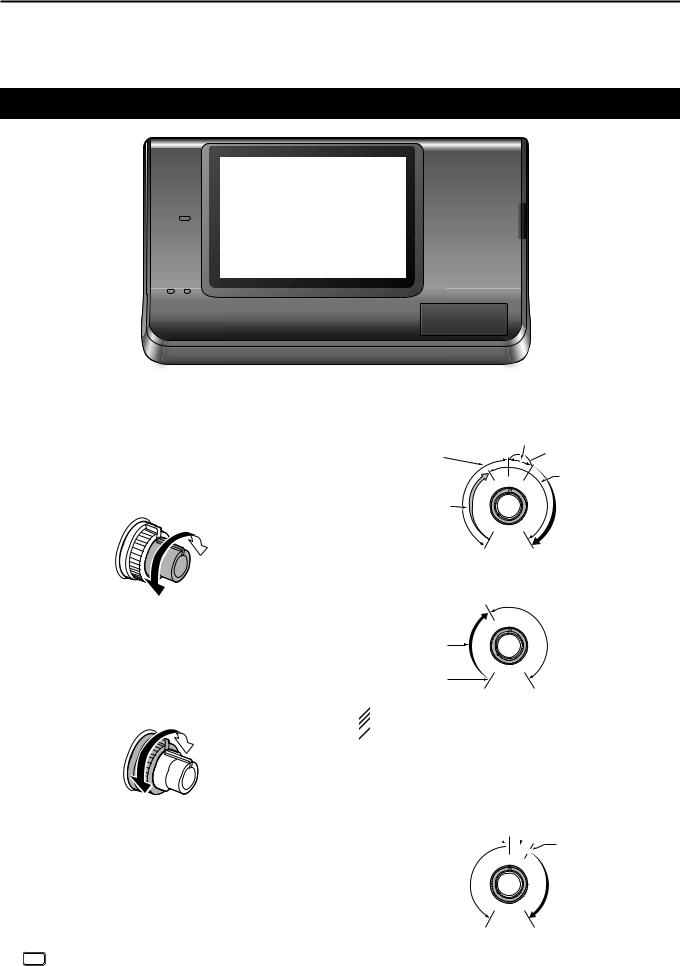
1 PANEL DESCRIPTION
Controller — Front panel
q w
e
r t
y u
PWR |
i7100 |
AF RF/SQL
TX / RX
CLR
M-CH BANK
BANK
PBT |
RIT |
RIT |
MENU |
NB |
NR |
NOTCH |
SET |
AUTO TUNE RX CS SPEECH |
TUNER/CALL |
MIC/RF PWR |
SPEED/PITCH |
P.AMP ATT |
DR |
QUICK |
XFC |
MPAD |
i o !0!1
qPOWER SWITCH•AF VOLUME [PWR]•[AF]
(p. 3-2)
Push to turn ON the transceiver power.
• First, confirm the DC power source is turned ON.
Hold down for 1 second to turn OFF the power.Rotate to adjust the audio output level.
Increases
Decreases
wRF GAIN CONTROL/ SQUELCH CONTROL
[RF/SQL] (p. 3-19)
Rotate to adjust the RF gain and squelch threshold levels.
The squelch removes noise output to the speaker when no signal is received. (closed condition)
•The squelch is particularly effective for AM and FM, but also works in other modes.
•The 12 to 1 o’clock position is recommended for the most effective use of the [RF/SQL] control.
•[RF/SQL] operates as only an RF gain control in SSB,
CW and RTTY (Squelch is fixed open), or a squelch control in AM, FM, WFM and DV (RF gain is fixed at maximum sensitivity), when “Auto” is selected as the “RF/SQL
Control” item in the “Function” Set mode. (p. 6-5)
SET > Function > RF/SQL Control
• When used as an RF gain/squelch control
Noise squelch (FM/DV modes)
Squelch is |
Recommended level |
|
|
||
open. |
Maximum |
|
|
||
|
RF gain |
|
RF gain |
|
|
adjustable |
S-meter |
|
range |
||
squelch |
||
|
•When used as an RF gain control
(Squelch is fixed open; SSB, CW and RTTY only)
Adjustable |
Maximum |
RF gain |
|
range |
|
Minimum RF gain |
|
 While rotating the RF gain control, a faint noise may
 be heard. This comes from the DSP unit and does
  not indicate an equipment malfunction.
•When used as a squelch control
(RF gain is fixed at maximum.)
Noise squelch (FM/DV modes)
Noise squelch
 threshold
 (FM/DV modes)
Squelch is open.
Shallow
S-meter squelch threshold
S-meter squelch
Deep
1-2

PANEL DESCRIPTION |
1 |
eTX/RX LED
Lights green when the squelch opens, or a signal is received.
Lights red when transmitting.
rMEMORY BANK CONTROL [BANK]
When both the PBT and RIT LEDs are OFF Rotate to select a Memory bank.
When the PBT LED (y) lights green
(Mode: SSB/CW/RTTY/AM)
Rotate to adjust the receiver’s IF filter passband width using the DSP circuit.
When the RIT LED (u) lights orange Disable this control.
tM-CH CONTROL•CLEAR SWITCH [M-CH]•[CLR]
Push to select the action of the [M-CH/BANK] controls as the Memory/Bank selection, PBT control or RIT control.
When the both RIT and PBT LEDs are OFF Rotate to select a Memory channel.
When the RIT LED lights orange
Rotate to adjust the RIT frequency shift.
• The frequency shift range is ±9.99 kHz in 10 Hz steps.The control tunes in 1 Hz steps when the operating frequency readout is set to the 1 Hz step.
Hold down for 1 second to clear the RIT shift frequency.
What is the RIT function?
The RIT (Receiver Incremental Tuning) shifts the receive frequency without shifting the transmit frequency. This is useful for fine tuning stations calling you off-fre- quency, or when you prefer to listen to slightly differentsounding voice characteristics.
When the PBT LED lights green
(Mode: SSB/CW/RTTY/AM)
Rotate to adjust the receiver’s IF filter passband width using the DSP circuit.
Hold down for 1 second to reset the PBT settings.
• The PBT is adjustable in 50 Hz steps in the SSB/
CW/RTTY modes, and 200 Hz in the AM mode. At that time, the shift value changes in 25 Hz steps in the SSB/CW/RTTY modes, and 100 Hz in the AM mode.
• The PBT controls function as an IF shift control.
What is the PBT control?
The PBT function electronically modifies the IF passband width to reject interference. This transceiver uses the DSP circuit for the PBT function.
1-3
yPBT LED
Lights green when the [M-CH/BANK] controls act as the PBT control.
• Push the [M-CH] switch to select PBT control.
uRIT LED
Lights orange when the RIT function is turned ON.Lights orange when the [M-CH/BANK] controls
act as the RIT control.
• Push the [M-CH] switch to select RIT control.
•The RIT control is the inner control. The outer control is disabled.
iRIT KEY RIT (AI sec. 5)
Push to turn the RIT function ON or OFF.
• Use the [M-CH] control to vary the RIT frequency.
Hold down for 1 second to add the shift frequency of the RIT function to, or subtract it from, the displayed frequency.
oANTENNA TUNER/CALL KEY TUNER/CALL
ANTENNA TUNER KEY Operation (AI sec. 16)
(Frequency band: HF/50 MHz)
Push to turn an optional automatic antenna tuner ON or OFF (bypass).
Hold down for 1 second to manually tune the antenna tuner.
• If the tuner cannot tune the antenna within 20 seconds, the tuning circuit is automatically bypassed.
CALL KEY Operation (AI sec. 11)
(Frequency band: 144/430 MHz)
Push to select the Call channel.
In the 70 MHz band, push to sound an error beep.
!0MENU KEY MENU (p. 1-10)
Push to change the set of functions assigned to the touch keys.
•Toggles the function display menu between M-1, M-2 and
M-3 menus or D-1 and D-2 menus.
!1MIC GAIN/RF POWER ADJUSTMENT KEY
 (p. 3-24)
Push to open the MIC gain/RF power adjustment display.
•Rotate [M-CH] to adjust the MIC gain.
•Rotate [BANK] to adjust the RF power.
Frequency band |
RF output power range |
|
HF/50 MHz |
2 to 100 W |
(AM: 1 to 30 W) |
70 MHz* |
2 to 50 W |
(AM: 1 to 15 W) |
144 MHz |
2 to 50 W |
|
430 MHz |
2 to 35 W |
|
•Push again to close the window.
*70 MHz band transmission is available, depending on the transceiver version.
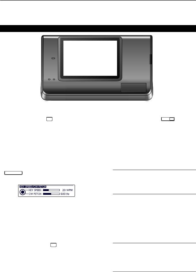
1 PANEL DESCRIPTION
Controller — Front panel (Continued)
PWR |
i7100 |
AF RF/SQL
TX / RX
CLR
M-CH BANK
BANK
PBT RIT
RIT |
MENU |
NB |
NR |
NOTCH |
SET |
TUNER/CALL |
MIC/RF PWR |
SPEED/PITCH |
P.AMP ATT |
DR |
QUICK |
AUTO TUNE RX CS |
SPEECH |
XFC MPAD
!2 !3!4!5 !6!7!8!9@0 @1
!2NOISE BLANKER KEY NB (AI sec. 5)
(Mode: SSB/CW/RTTY/AM)
Push to turn the noise blanker ON or OFF.
The noise blanker reduces pulse-type noise such as that generated by vehicle ignition systems. The noise blanker is not effective for non-pulse-type noise.
• “NB” appears when the noise blanker is ON.
Hold down for 1 second to display the “NB” screen. Push to return to the previous screen.
!3KEY SPEED/CW PITCH ADJUSTMENT KEY
SPEED/PITCH (AI sec. 4, 6)
Push to open the Key speed/CW pitch adjustment display.
•Rotate [M-CH] to adjust the keying speed of the internal electronic CW keyer to between 6 wpm (minimum) and 48 wpm (maximum).
•Rotate [BANK] to shift the received CW audio pitch and the CW sidetone pitch without changing the operating frequency.
•The CW pitch can be adjusted from 300 to 900 Hz in approximately 5 Hz steps.
•Push again to close the window.
!4NOISE REDUCTION KEY NR (AI sec. 5)
Push to turn DSP noise reduction ON or OFF.
• “NR” appears when noise reduction is ON.
Hold down for 1 second to display the “NR” screen. Push to return to the previous screen.
•Rotate the Dial to adjust the DSP noise reduction level. Set for maximum readability.
!5PREAMP•ATTENUATOR KEY P.AMP ATT
PREAMP KEY Operation (AI sec. 5)
(Frequency band: HF, 50/70 MHz)
Push to select one of two receive RF preamplifiers, or to bypass them.
• “P. AMP1” is a wide dynamic range preamplifier. It is most effective for the 1.8 to 21 MHz bands.
• “P. AMP2” is a high-gain preamplifier. It is most effective for the 24 to 70 MHz bands.
• No indicator appears when the preamplifiers are not selected.
What is the preamplifier?
The preamplifier amplifies signals in the front end to improve the S/N ratio and sensitivity. Select “P. AMP1” or “P. AMP2” when receiving weak signals.
(Frequency band: 144/430 MHz)
Push to turn the preamplifier ON or OFF.
•“P.AMP” appears when the preamplifier is ON.
ATTENUATOR KEY Operation (AI sec. 5)
Hold down for 1 second to turn ON the attenuator.
•“ATT” appears when the attenuator is ON.
Push to turn OFF the attenuator.
•“ATT” disappears.
What is the attenuator?
The attenuator prevents a desired signal from being distorted when very strong signals are near it, or when very strong electromagnetic fields, such as from a broadcasting station, are near your location.
1-4

PANEL DESCRIPTION |
1 |
!6NOTCH KEY NOTCH (AI sec. 5)
(Mode = Auto notch: SSB/AM/FM Manual notch: SSB/CW/RTTY/AM)
In the SSB and AM modes, push to toggle the notch function between auto, manual and OFF.
•Either the Auto or Manual notch function can be turned
OFF in the “[NOTCH] Switch (SSB)/(AM)” items of the “Function” Set mode. (6-21)
SET > Function > [NOTCH] Switch (SSB) SET > Function > [NOTCH] Switch (AM)
In the FM mode, push to turn the Auto Notch function ON or OFF.
In the CW or RTTY mode, push to turn the Manual Notch function ON or OFF.
• “MN” appears when the Manual Notch function is
ON.
• “AN” appears when the Auto Notch function is ON. • No indicator appears when the notch filter is OFF.
Hold down for 1 second to display the “NOTCH” screen.
Push to return to the previous screen.
•Rotate the Dial to adjust the notch frequency to reject an interfering signal when the manual function is ON.
• Notch filter center frequency:
SSB/RTTY: –1040 Hz to +4040 Hz
CW: |
CW pitch frequency –2540 Hz to |
|
CW pitch frequency +2540 Hz |
AM: |
–5060 Hz to +5100 Hz |
What is the notch filter?
The notch filter is a narrow filter that eliminates unwanted CW or AM carrier tones, while preserving the desired voice signal. The DSP circuit automatically adjusts the notch frequency to effectively eliminate unwanted tones.
!7DR MODE KEY DR (section 4, 5, AI sec. 9) Push to select the DR mode.
• When the DR mode is selected, the transceiver automatically selects the DV mode.
In the DR mode, push to cancel it.
• The transceiver returns to the previous screen before entering the DR mode.
!8SET MODE KEY SET (section 6)
Push to enter or exit the SET mode.
• “Voice Memo,” “Call Sign,” “RX History,” “DV Memory,” “My Station,” “DV Set,” “GPS,” “SPEECH,” “QSO/RX
Log,” “Function,” “Tone Control,” “Connectors,” “Display,” “Time Set,” “SD Card” and “Others” set group are selectable.
!9QUICK MENU KEY QUICK
Push to open or close the Quick Menu window.
• The Quick Menu is used to quickly select various functions.
In the setting screen, push to open the Default set window.
• Touch “Default” to reset to the default setting.
@0AUTO TUNE•RXCS KEY AUTO TUNE RX CS
AUTO TUNE KEY Operation (AI sec. 4)
(Mode: CW)
Push to automatically adjust for a zero beat with the received signal.
Zero beat means that two signals are exactly the same frequency.
•“AUTO TUNE” blinks when the auto tune function is activated.
•When the RIT function is ON, the auto tune function changes the RIT frequency, not the displayed frequency.
RX CALL SIGN CAPTURE KEY Operation (p. 5-6)
(Mode: DV, when the DR mode is selected)
Push to open the “RX>CS” screen.
Push again to return to the previous screen.
Hold down for 1 second to set the received call signs (station and repeaters) as the operating call sign.
@1TRANSMIT FREQUENCY CHECK KEY XFC
During split frequency or repeater operation, hold down to listen to the transmit frequency. (AI sec. 4)
• While holding down this switch, the transmit frequency can be changed with the Dial or MPAD .
• When the Split Lock function is turned ON in the Split operation, hold down XFC to cancel the Dial lock function.
When operating simplex, hold down to monitor the frequency.
• While holding down this key, the squelch is open and the interference reject function is temporarily turned OFF.
When operating simplex and the RIT function is turned ON, hold down to listen to the transmit frequency. The frequency is the same as when the RIT is OFF.
In the DV mode, hold down this key to select the RX monitoring mode. (p. 6-3)
1-5
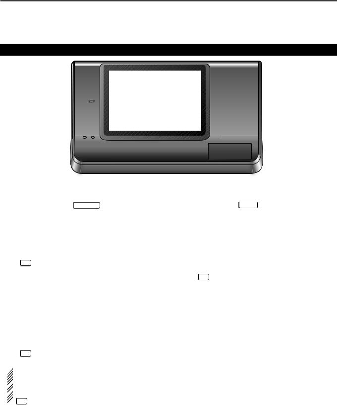
1 PANEL DESCRIPTION
Controller — Front panel (Continued)
PWR |
i7100 |
AF RF/SQL
TX / RX
CLR
M-CH BANK
BANK
PBT RIT
 @5 @4
@5 @4
RIT |
MENU |
NB |
NR |
NOTCH |
SET |
TUNER/CALL |
MIC/RF PWR |
SPEED/PITCH |
P.AMP ATT |
DR |
QUICK |
AUTO TUNE RX CS |
SPEECH |
XFC |
MPAD |
@2 @3
@2SPEECH•LOCK KEY SPEECH
SPEECH KEY Operation (p. 3-20)
Push to audibly announce the S-meter level, the displayed frequency and the operating mode.
• The S-Level announcement can be turned OFF in the
“S-Level SPEECH” item of the “SPEECH” Set mode. (p. 6-4)
SET > SPEECH > S-Level SPEECH
•When RIT is ON, the RIT offset is not included in the frequency announcement.
LOCK KEY Operation (AI sec. 5)
Hold down for 1 second to turn the Lock function ON or OFF.
@3MEMO PAD KEY MPAD (AI sec. 11)
Push to sequentially call up the contents from the memo pad.
The 5 (or 10) most recently programmed frequencies and operating modes can be recalled, starting from the most recent.
• The memo pad capacity can be increased from 5 to
10 in the “Memopad Numbers” item of the “Function” Set mode (p. 6-6)
SET > Function > Memopad Numbers
Hold down for 1 second to write the displayed data into a memo pad.
• The 5 most recent entries remain in the memo pad.
•The function electronically locks the Dial.
•“  ” appears when the function is ON.
• You can select the Dial lock and Panel lock in the
“Lock Function” item of the “Function” Set mode. (p. 6-6)
SET > Function > Lock Function
 NOTE: The [SPEECH/LOCK] key operation to ac-
tivate the voice synthesizer or the Lock functions
 can be replaced in the “[SPEECH/LOCK] Switch”
  item of the “Function” Set mode. (p. 6-6)
 SET > Function > Lock Function
@4MAIN DIAL
Rotate to change the displayed frequency, select the Set mode settings, and so on.
@5MAIN DIAL TENSION LATCH
Select the Dial drag.
•Three positions are selectable. The top setting turns on clicks as the dial is turned.
1-6
PANEL DESCRIPTION |
1 |
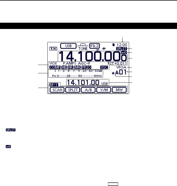
Controller — Function display
q |
w |
e r t y u i |
q TX ICON
Indicates either the displayed frequency can be transmitted, or not.
“ ” appears while the operating frequency is in an amateur band.
“ ” appears while the operating frequency is not in an amateur band. However, when the “Band Edge Beep” item is set to “OFF” in the “Function” Set mode (p. 6-5), “
 ” does not appear.
SET > Function > Band Edge Beep
“LMT” appears while the output power is decreased because the Power FET’s temperature is high.
“HOT” appears while transmission is inhibited because the Power FET’s temperature is too high.
w MODE ICONS (p. 3-17)
Displays the selected operating mode.
•“-D” appears when SSB data, AM data or FM data mode is selected.
Touch to enter the Mode selection screen.
•On the Mode selection screen, touch the block to select the operating mode.
e PASSBAND WIDTH ICON (AI sec. 5)
Graphically displays the passband width for twin PBT operation and the center frequency for IF shift operation.
r TONE SQUELCH/DIGITAL SQUELCH ICONS
(Mode: FM)
“TONE” appears when the repeater tone function is ON. (AI sec. 4)
“TSQL” appears when the tone squelch function is ON. (AI sec. 4)
“DTCS” appears when the DTCS function is ON. (AI sec. 4)
(Mode: DV)
“DSQL” appears when the digital call sign squelch function is ON. (AI sec. 9)
“CSQL” appears when digital code squelch function is ON. (AI sec. 9)
t IF FILTER ICON (AI sec. 5)
Shows the selected IF filter.
Touch to select one of three IF filter settings.
•The selected filter passband width and shifting value are displayed for 2 seconds in the window.
Touch for 1 second to display the “FILTER” screen to adjust the filter passband width.
When the “FILTER” screen is displayed, touch for 1 second to return to the previous screen.
y QUICK TUNING ICON (p. 3-8)
Appears when the Quick tuning mode is selected.
•When “Z” is displayed, the frequency changes in preset kHz or 1 MHz quick tuning steps.
•When “Z” is not displayed, the frequency changes in 10 Hz or 1 Hz steps.
u GPS ICON (AI sec. 10)
Appears when valid position data is received from a GPS receiver that is connected to the [DATA1] jack.
Blinks when invalid data is received from the GPS receiver.
iSD CARD ICON
“ ” appears when an SD card is inserted.
“ ” and “

 ” alternately blinks while accessing the SD card.
1-7
1 PANEL DESCRIPTION
Controller — Function display (Continued)
|
o |
|
|
!0 |
|
|
!1 |
|
|
!2 |
|
!9 |
!3 |
|
|
||
!8 |
!4 |
|
!5 |
||
|
||
|
!6 |
|
!7 |
|
o CLOCK READOUT |
!4 MEMORY CHANNEL READOUT (AI sec. 11) |
|
Shows the current time. |
Shows the selected memory channel, scan edge |
|
• UTC time or local time can be selected. |
channel or Call channel. |
|
|
|
• Memory bank indicator (A to E) appears to the left of |
!0SPLIT ICON (AI sec. 6) |
memory channel. |
|
“ |
” appears when the Split function is turned |
Touch to toggle between the VFO and Memory |
ON. |
|
modes. |
!1 LOCK ICON (AI sec. 5) |
!5SELECT MEMORY CHANNEL ICON |
|
“” appears when the selected memory channel is |
||
“ ” appears when the Lock function is activated. |
||
set as a select memory channel. (AI sec. 12) |
||
|
1⁄4 TUNING DIAL SPEED ICON (p. 3-10)
(Mode: SSB-D/CW/RTTY)
“  ” appears when the tuning dial speed is set so that one rotation is equal to 1⁄4 of the normal rotation.
•This function is selectable only when the quick tuning function is turned OFF.
!2FREQUENCY READOUTS
Displays the operating frequency.
Touch the MHz digits to enter the Band selection screen.
Touch the MHz digits for 1 second to turn the 1 MHz quick tuning mode ON or OFF.
Touch the kHz digits to turn the preset kHz quick tuning mode ON or OFF.
Touch the kHz digits for 1 second to enter the Tuning step selection screen.
Touch the Hz digits to for 1 second to toggle between 10 Hz and 1 Hz steps.
!3VFO/MEMORY ICONS (p. 3-4)
“VFOA” or “VFOB” appears whether VFO A or VFO B is selected.
“MEMO” appears when the memory mode is selected.
!6INFORMATION READOUT
Displays the transmit frequency of the Split operation, descriptions of the memory channel or Received Call sign in the DV mode, and so on.
!7FUNCTION DISPLAY (p. 1-10) Shows the function of the Touch keys.
•Push MENU to change the set of functions assigned to the touch keys.
•Toggles the function display menu between M-1, M-2 and
M-3 menus or D-1 and D-2 menus.
!8MULTI-FUNCTION METER INDICATION
Displays the signal strength while receiving.
Displays the relative output power, SWR, ALC or compression levels while transmitting.
When the Meter Peak Hold function is ON, the peak level of a received signal strength or the output power is displayed for approximately 0.5 seconds.
Touch to select the RF power, SWR, ALC or Compression meter.
Touch for 1 second to display the Multi-function meter.
1-8

!9FUNCTION ICONS
“VOX” appears when the VOX function is activated. (AI sec. 6)
The Break-in icons appear when the Break-in function is turned ON. (AI sec. 6)
•“F-BKIN” appears when the Full Break-in function is turned ON.
•“BK-IN” appears when the Semi Break-in function is turned ON.
The Preamp icons appear when a preamplifier is turned ON. (AI sec. 5)
•In the HF, 50/70 MHz frequency band, either
“P.AMP1” or “P.AMP2” is displayed when preamp 1 or preamp 2 is ON.
•In the 144/430 MHz frequency band, “P.AMP” is displayed when the preamp is ON.
“ATT” appears when the Attenuator function is turned ON. (AI sec. 5)
The AGC icons display the selected AGC time constant. (AI sec. 5)
•“AGC-F” for AGC fast;“AGC-M” for AGC mid;“AGC-S” for AGC slow; “AGC-OFF” for AGC OFF.
•In the FM, WFM and DV mode, “AGC-F” for AGC fast is fixed.
“DUP+” appears when plus duplex, “DUP –” appears when minus duplex (repeater) operation is selected. (AI sec. 4)
“RIT” and the shift frequency are displayed when the RIT function is turned ON. (AI sec. 5)
“ ” appears when the Speech Compressor function is turned ON.
“  ” appears when the Noise Blanker function is turned ON. (AI sec. 5)
“ ” appears when the Noise Reduction function is turned ON. (AI sec. 5)
The Notch icons appear when the Notch filter function is turned ON. (AI sec. 5)
(Mode: SSB/CW/RTTY/AM)
•“  ” appears when the Manual Notch function is turned ON.
(Mode: SSB/AM/FM)
•“  ” appears when the Automatic Notch function is turned ON.
“  ” appears when priority scan is turned ON. (AI sec. 12)
“  ” appears when the VSC (Voice Squelch Control) function is turned ON.
PANEL DESCRIPTION |
1 |
(Mode: DV)
“ ” appears when the EMR (Enhanced Monitor Receive) communication mode is selected. (AI sec. 9)
•In the EMR communication mode, no call sign setting is necessary when operating in the DV mode.
“ ” blinks when receiving an EMR signal.
“  ” appears when the BK (Break-in) function is turned ON. (AI sec. 9)
•The BK function allows you to break into a conversation where the two other stations are communicating with call sign squelch enabled.
“  ” blinks when receiving a break-in call.
1-9
1 PANEL DESCRIPTION
Controller — Multi-function keys
Push MENU to change the set of functions assigned to touch keys.
•Toggles the function display menu between M-1, M-2 and
M-3 menus or D-1 and D-2 menus.
•Functions vary, depending on the operating mode.
•In the DR mode, the D-1 and D-2 menus can be selected.
Touch or touch for 1 second to select the displayed functions.
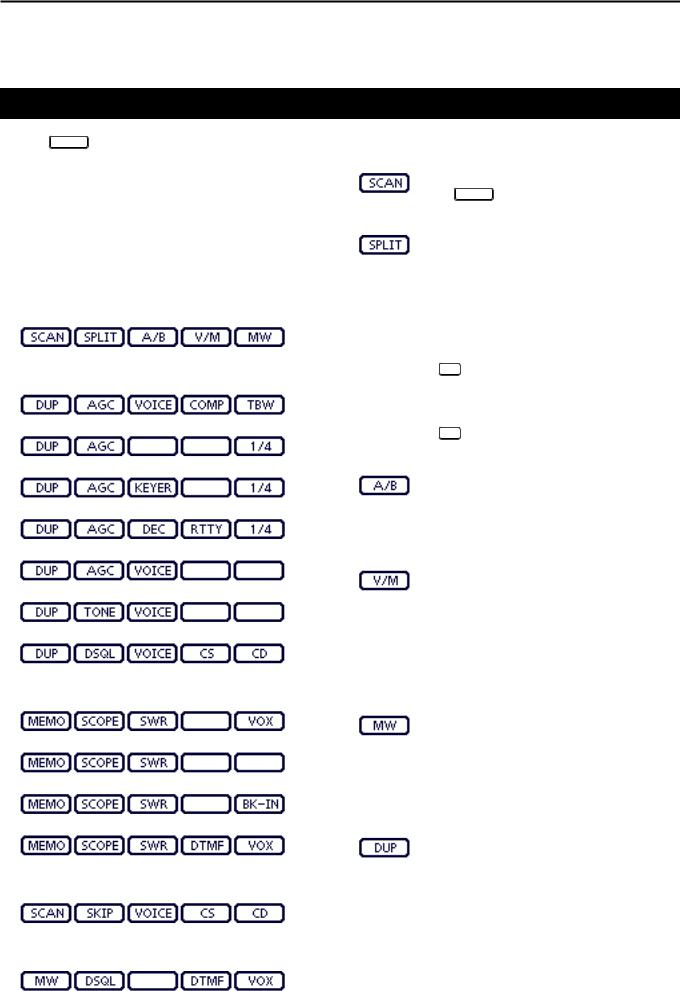
DDM-1 (M-1 menu) Display
DDM-2 (M-2 menu) Display
(Mode: SSB)
(Mode: SSB-D)
(Mode: CW)
(Mode: RTTY)
(Mode: AM/AM-D)
(Mode: FM/FM-D/WFM)
(Mode: DV)
DDM-3 (M-3 menu) Display
(Mode: SSB/AM/AM-D)
(Mode: SSB-D/RTTY)
(Mode: CW)
(Mode: FM/FM-D/WFM/DV)
DDD-1 (D-1 menu) Display
(Mode: DV, when the DR mode is selected)
DDD-2 (D-2 menu) Display
(Mode: DV, when the DR mode is selected)
DDFunction keys on M-1 display
SCAN KEY [SCAN] (AI sec. 12)
Touch to display the “SCAN” screen.
• Push MENU to return to the previous screen.
SPLIT KEY [SPLIT] (AI sec. 6)
Touch to turn the split function ON or OFF.
•“ ” appears when the split function is ON.
Touch for 1 second to activate the quick split function.
• The transmit frequency shifts from the receive frequency according to the “SPLIT Offset” option in the “Function” Set mode. (AI sec. 6)
SET > Function > SPLIT/DUP > SPLIT Offset
• The quick split function can be turned OFF in the “Quick SPLIT” item of the “Function” Set mode. (AI sec. 6)
SET > Function > SPLIT/DUP > Quick SPLIT
VFO SELECT KEY [A/B] (p. 3-5)
Touch to select either VFO A or VFO B.
Touch for 1 second to equalize the undisplayed VFO settings to that of the displayed VFO.
VFO/MEMORY KEY [V/M]
Touch to switch between the VFO and memory modes. (p. 3-4)
• Touching Memory channel also selects the
VFO or memory modes.
Touch for 1 second to copy the memory contents to the displayed VFO. (AI sec. 11)
MEMORY WRITE KEY [MW] (AI sec. 11)
Touch for 1 second to store VFO data into the selected memory channel.
•This can be done in both the VFO and memory modes.
DDFunction keys on M-2 display
DUPLEX KEY [DUP] (AI sec. 4)
Touch to select the duplex direction, or to turn OFF the function.
•“DUP–” or “DUP+” is displayed during duplex operation.
In the FM mode, touch for 1 second to turn the one-touch repeater function ON or OFF.
1-10
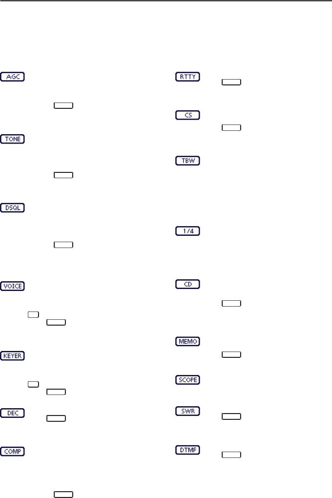
AGC KEY [AGC] (AI sec. 5)
(Mode: SSB/SSB-D/CW/RTTY/AM/AM-D)
Touch to select the time constant of the AGC circuit.
Touch for 1 second to display the “AGC” screen.
• Push MENU to return to the previous screen.
TONE SQUELCH KEY [TONE] (AI sec. 4)
(Mode: FM)
Touch to select a tone function between subaudible (repeater) tone, tone squelch and DTCS.
Touch for 1 second to display the “TONE” screen of the selected tone function.
• Push MENU to return to the previous screen.
DIGITAL SQUELCH KEY [DSQL] (AI sec. 9)
(Mode: DV)
Touch to select a digital squelch function between digital call sign squelch and digital code squelch.
Touch for 1 second to display the “DSQL” screen (digital squelch).
• Push MENU to return to the previous screen.
VOICE RECORDER KEY [VOICE] (AI sec. 15)
(Mode: SSB/AM/FM/DV)
This function requires to insert an SD card.
Touch to display the “VOICE TX” screen or the “VOICE” (Root) screen, depending on the “VOICE 1st Menu” option in the “Function” Set mode (p. 6-6).
SET > Function > VOICE 1st Menu
• Push MENU to return to the previous screen.
MEMORY KEYER KEY [KEYER] (AI sec. 4)
(Mode: CW)
Touch to display the “KEYER SEND” screen or the “KEYER” (Root) screen, depending on the “KEYER 1st Menu” option in the “Function” Set mode (p. 6-6).
SET > Function > KEYER 1st Menu
• Push MENU to return to the previous screen.
RTTY DECODER KEY [DEC] (AI sec. 4)
Touch to display the RTTY Decoder screen.
• Push MENU to return to the previous screen.
SPEECH COMPRESSOR KEY [COMP] (AI sec. 6)
(Mode: SSB)
Touch to turn the speech compressor function ON or OFF.
•“ ” is displayed when the speech compressor is ON.
Touch for 1 second to display the “COMP” screen.
•Push MENU to return to the previous screen.
PANEL DESCRIPTION |
1 |
RTTY SET KEY [RTTY] (AI sec. 6)
Touch to display the “RTTY SET” screen.
• Push MENU to return to the previous screen.
CALL SIGN KEY [CS] (AI sec. 4)
(Mode: DV)
Touch to display the “CALL SIGN” screen.
•The current call sign for DV operation appears.
•Push MENU to return to the previous screen.
TRANSMISSION BANDWIDTH KEY [TBW] (AI sec. 6)
(Mode: SSB)
Touch to display the selected transmission bandwidth.
Touch for 1 second to select the transmission bandwidth.
•Bandwidth is selectable from wide (WIDE), mid (MID) and narrow (NAR).
1⁄4 TUNING FUNCTION KEY [1⁄4] (p. 3-10)
(Mode: SSB-D/CW/RTTY)
Touch to turn the 1⁄4 Tuning function ON or
OFF.
•“  ” is displayed when the 1⁄4 Tuning function is ON.
CALL RECORD KEY [CD] (AI sec. 9)
(Mode: DV)
Touch to display the “RX HISTORY” screen.
•The call record channel appears. (RX01 to RX20)
•Push MENU to return to the previous screen.
DDFunction keys on M-3 display
MEMORY NAME KEY [MEMO] (AI sec. 11)
Touch to display the “MEMO” (Memory menu) screen.
• Push MENU to return to the previous screen.
BAND SCOPE FUNCTION KEY [SCOPE] (AI sec. 5) Touch to display the “SCOPE” (Band scope) screen.
SWR GRAPH FUNCTION KEY [SWR] (AI sec. 6) Touch to display the “SWR” screen.
• Push MENU to return to the previous screen.
DTMF MODE KEY [DTMF] (AI sec. 6)
(Mode: FM/FM-D/DV)
Touch to display the “DTMF” screen.
• Push MENU to return to the previous screen.
1-11
1 PANEL DESCRIPTION
Controller — Multi-function keys
DDFunction keys on M-3 display (Continued)
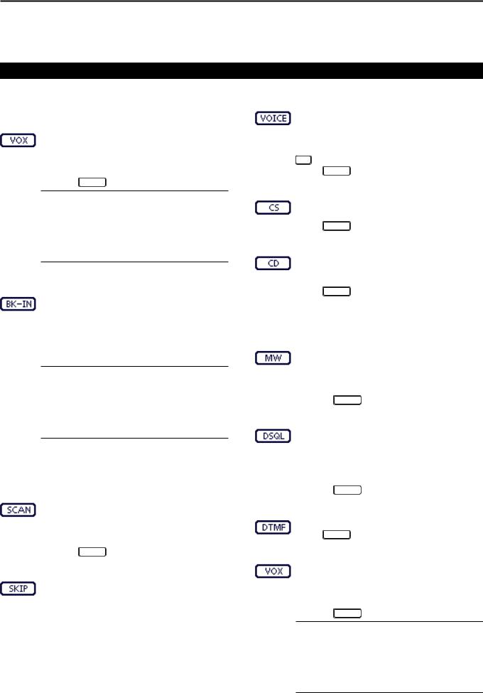
VOX KEY [VOX] (AI sec. 6)
(Mode: SSB/AM/FM/DV)
Touch to turn the VOX function ON or OFF.
Touch for 1 second to display the “VOX” screen.
•Push MENU to return to the previous screen.
What is the VOX function?
The VOX function (voice operated transmission) automatically starts transmission when you speak into the microphone, then automatically returns to receive when you stop speaking.
BK-IN KEY [BK-IN] (AI sec. 6)
(Mode: CW)
Push to toggle the break-in operation between semi break-in and full break-in, or to turn OFF the break-in function.
Hold down for 1 second to display the “BKIN” screen (Break-in). Push to return to the previous screen display.
What is the break-in function?
The break-in function automatically switches between transmit and receive with your CW keying. Using Full break-in function (QSK), you can hear the receive frequency in-be- tween keying.
DDFunction keys on D-1 display
(Mode: DV) (when the DR mode is selected)
SCAN KEY [SCAN] (AI sec. 12)
Touch to start or cancel the Access repeater scan.
Touch for 1 second to enter the “SCAN SET” mode screen.
• Push MENU to return to the previous screen.
SKIP KEY [SKIP]
Touch to set the Skip setting ON or OFF for the Access repeater scan.
•“ ” is displayed when the Skip setting is ON.
•When a repeater is set as a skip target, the repeater cannot be selected in “FROM” (Access repeater).
VOICE RECORDER KEY [VOICE] (AI sec. 15) This function requires to insert an SD card.
Touch to display the “VOICE TX” screen or the “VOICE” (Root) screen, depending on the “VOICE 1st Menu” option in the “Function” Set mode (p. 6-6).
SET > Function > VOICE 1st Menu
• Push MENU to return to the previous screen.
CALL SIGN KEY [CS] (AI sec. 9)
Touch to display the “CALL SIGN” screen.
•The current call sign for DV operation appears.
•Push MENU to return to the previous screen.
CALL RECORD KEY [CD] (AI sec. 9)
Touch to display the “RX HISTORY” screen.
•The call record channel appears. (RX01 to RX20)
•Push MENU to return to the previous screen.
DDFunction keys on D-2 display
(Mode: DV) (when the DR mode is selected)
MEMORY WRITE SWITCH [MW] (AI sec. 11)
Touch to display the Memory channel screen.
•Touch [MW] for 1 second to store the DR mode data into the selected memory channel.
•Push MENU to return to the previous screen.
DIGITAL SQUELCH KEY [DSQL] (AI sec. 9)
Touch to select a digital squelch function between digital call sign squelch and digital code squelch.
Touch for 1 second to display the “DSQL” screen (digital squelch).
• Push MENU to return to the previous screen.
DTMF MODE KEY [DTMF] (AI sec. 6) Touch to display the “DTMF” screen.
• Push MENU to return to the previous screen.
VOX KEY [VOX] (AI sec. 6)
Touch to turn the VOX function ON or OFF.
Touch for 1 second to display the “VOX” screen.
•Push MENU to return to the previous screen.
What is the VOX function?
The VOX function (voice operated transmission) automatically starts transmission when you speak into the microphone; then automatically returns to receive when you stop speaking.
1-12
PANEL DESCRIPTION |
1 |
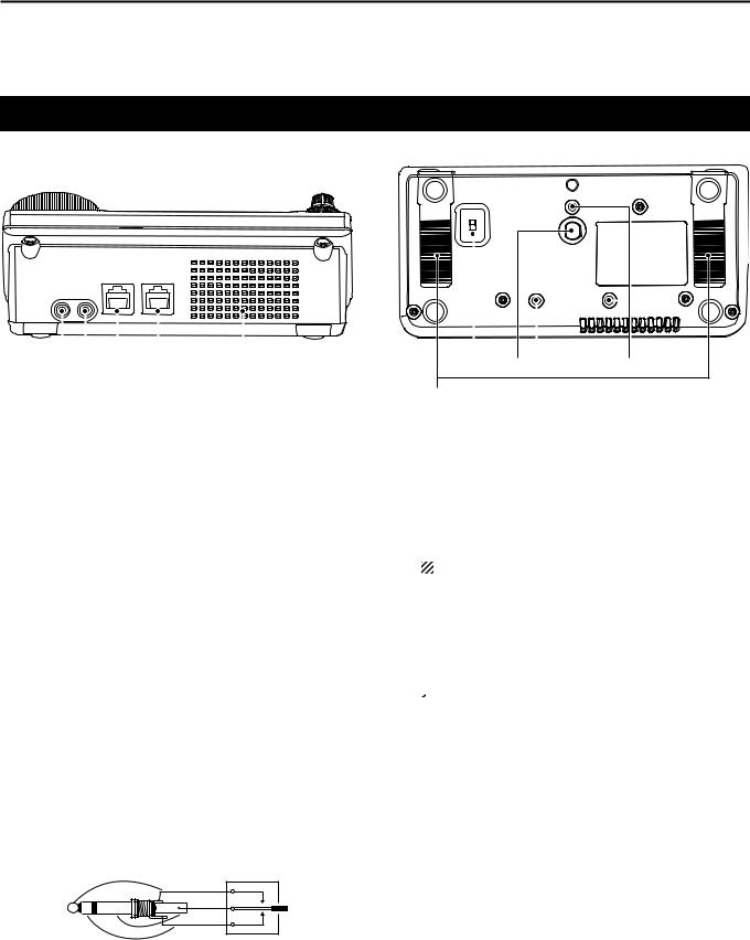
Controller — Rear and bottom panels
Bottom panel
Rear panel
|
|
|
|
|
|
|
|
|
|
|
|
|
|
|
|
|
|
|
|
|
|
|
|
|
|
|
|
|
|
|
|
|
|
|
|
|
|
|
|
|
|
|
|
|
|
|
|
|
|
|
|
|
|
|
|
|
|
|
|
|
|
|
|
|
|
|
|
|
|
|
|
|
|
|
|
|
|
|
|
|
|
|
|
|
|
|
|
|
|
|
|
|
|
|
|
|
|
|
|
|
|
|
|
|
|
|
|
|
|
|
|
|
|
|
|
|
|
|
|
|
|
|
|
|
|
|
|
|
|
|
|
|
|
|
|
|
|
|
|
|
|
|
|
|
|
|
|
|
|
|
|
|
|
|
|
|
|
|
|
|
|
|
|
|
|
|
|
|
|
|
|
|
|
|
|
|
|
|
|
|
|
|
|
|
|
|
|
|
|
|
|
|
|
|
|
|
|
|
|
|
|
|
|
|
|
|
|
|
|
|
|
|
|
|
|
|
|
|
|
|
|
|
|
|
|
|
|
|
|
|
|
|
|
|
|
|
|
|
|
|
|
|
|
|
|
|
|
|
|
|
|
|
|
|
|
|
|
|
|||||||||||||||||||||
q w e r |
Speaker |
y u |
|
|
i |
|||||||||||||||||||||||||||||
t
qHEADPHONE/SPEAKER JACK [PHONES/SP]
Plug in standard stereo headphones (impedance: 8 to 16 ø).
• Output power: More than 5 mW with an 8 ø load. • When headphones are connected, the internal speaker, and any external speaker, are disabled.
•When the [PHONES/SP] switch (y) on the bottom panel is set to the SPEAKER position, an external speaker can be used instead of headphones. This is convenient for mobile or outdoor operation.
wELECTRONIC KEYER JACK [ELEC-KEY]
Plug in a bug or paddle type key to use the internal electronic keyer for CW operation. (AI sec. 4)
• Set the keyer type to ELEC-KEY, BUG-KEY or Straight key in the “Keyer Type” item of the “KEYER SET” mode.
• When a straight key is connected, “Straight key” must be selected in the “Keyer Type” item of the “KEYER SET” mode. (AI sec. 4)
• A straight key jack is located on the rear panel.See [KEY] on pages 1-15 and 2-5.
• You can reverse the keyer paddle polarity (dot and dash) in the “Paddle Polarity” item of the “KEYER SET” mode. (AI sec. 4)
• Four keyer memory channels are available for your convenience. (AI sec. 4)
(dot)
(com)
(dash)
A standard 3.5(d) mm/ 1⁄8 inch plug
eMICROPHONE CONNECTOR [MIC]
Plug in the supplied or an optional microphone.
• See AI sec. 21 for appropriate microphones. • See p. 1-17 for microphone connector information.
•The optional OPC-589 cable can be used to connect an
8-pin microphone such as the SM-30 or SM-50.
•A microphone connector is also available on the Main unit.
DO NOT simultaneously connect two microphones.
rMAIN UNIT CONNECTOR [MAIN UNIT]
Connects to the Main unit using with the supplied OPC-2253 Control cable.
•The OPC-2253 Control cable is 3.5 meter (11.5 feet) long.
 DO NOT use any third party’s Ethernet cables.
tSTAND
The length of the stand can be adjusted in two steps.
•Adjust to the length not to incline back when you operate the Front panel.
yPHONES/SPEAKER SWITCH [PHONE/SP]
Selects the [PHONES/SP] jack to connect a Headphones or external speaker.
uSCREW HOLE FOR STAND
Accepts the screw of a tripod stand. (Third party product.)
iSCREW HOLES FOR CONTROLLER BRACKET
Accepts the screws of the optional MBA-1 Controller bracket.
•The MBA-1 is required to install to the optional MBF-1
Mounting base.
1-13
1 PANEL DESCRIPTION
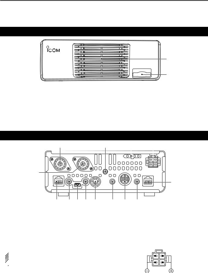
Main unit — Front panel
|
q |
|
w |
qCOOLING FAN |
wSD CARD SLOT [SD CARD] |
This is a cooling fan for heat dissipation. |
Insert an SD card of up to 32 GB SDHC. |
Depending on the internal temperature, it rotates at |
See AI sec. 13 for details. |
a Low, Mid or High speed. |
|
Main unit — Rear panel
w |
e |
r |
t |
||
|
|
|
|
|
|
|
|
|
|
|
|
|
|
|
|
|
|
q |
!4!3!2!1 !0
q ANTENNA CONNECTOR 1 [ANT1]
w ANTENNA CONNECTOR 2 [ANT2] (p. 2-2) Connect a 50 ø antenna with a PL-259 plug connector.
• [ANT1] is used for the HF, 50/70 MHz frequency bands. • [ANT2] is used for the 144/430 MHz frequency bands. • [ANT1] is used below 74.8 MHz, and [ANT2] is used for
74.8 MHz or above.
 When using an optional AH-4 or AT-180 hf/50 mhz
automatic antenna tuners, connect it to the  [ANT1] connector.
e GROUND TERMINAL [GND] (p. 2-2)
Connect this terminal to ground to prevent electrical shocks, TVI, BCI and other problems.
y
o i u
r TUNER CONTROL SOCKET [TUNER] (p. 2-6) Connect the control cable from an optional AH-4 hf/
50 mhz automatic antenna tuner.
t DC POWER SOCKET [DC 13.8V] (p. 2-7) Connect 13.8 V DC through the supplied DC power cable.
Rear panel view
yCONTROLLER CONNECTOR [CONTROLLER]
Connects to the Controller using with the supplied OPC-2253 Control cable.
•The OPC-2253 Control cable is 3.5 meter (11.5 feet) length.
•DO NOT use any third party’s Ethernet cables.
1-14
PANEL DESCRIPTION |
1 |
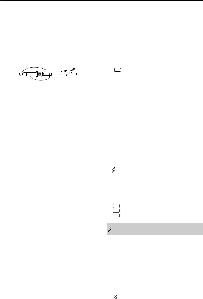
u STRAIGHT KEY JACK [KEY] (p. 2-5)
Connect a straight key or external electronic keyer using a standard 3.5(d) mm/ 1⁄8 inch plug.
• To use the internal electronic keyer for CW operation, connect to [ELEC-KEY] on the Front panel of the Controller. (p. 1-13)
(+)
(_)
i ACCESSORY SOCKET [ACC]
Connect control lines for external equipment such as a linear amplifier, an automatic antenna selector/ tuner, a TNC for data communications, and so on.
• See page 1-16 for socket information.
o DATA1 JACK [DATA1] (p. 2-6)
Connect a PC through the optional OPC-1529R data communication cable, for low-speed data communication in the DV mode. (AI sec. 9)
Connect a GPS receiver through the optional
OPC-1529R data communication cable, for GPS operation. (AI sec. 10)
!0DATA2 SOCKET [DATA2] (p. 2-6)
Connect a TNC (Terminal Node Controller), and so on, for high speed data communications.
!1CI-V REMOTE CONTROL JACK [REMOTE]
(p. 2-6)
Connect a PC, using the optional CT-17 ci-v level converter, for external control of the transceiver.
Use for the transceive function with another Icom CI-V transceiver or receiver.
When the transceive function is set to ON, changing the frequency, operating mode and so on, on the IC-7100 automatically changes those settings on other Icom transceivers or receivers, and vice versa.
Connect another IC-7100, using a mini plug cable*, for transceiver to transceiver cloning.
* Purchase separately
!2USB (Universal Serial Bus) PORT [USB]
Using a USB cable, connect a PC to do the following:
-Input modulation
-Remotely control the transceiver using CI-V commands (AI sec. 20)
-Send the received audio to the PC
-Send the decoded characters to the PC
-Low-speed data communication in the DV mode (AI sec. 9)
-Cloning using the optional CS-7100 cloning soft- ware (AI sec. 21)
-Remote control operation using the optional RSBA1 ip remote control software (AI sec. 21)
•Two COM port numbers are assigned to the [USB] connector. One of them is “USB1,” used for cloning and CI-V operation. The other one is “USB2,” whose function is selected in “USB2 Function” item of the “Connectors” Set mode. (p. 6-8)
SET > Connectors > USB2/DATA1 Function >
USB2 Function
About the USB driver:
The USB driver and the installation guide can be downloaded from our website.
http://www.icom.co.jp/world/index.html
The following items are required:
PC
•Microsoft® Windows® XP, Microsoft® Windows Vista®, Microsoft® Windows® 7 or Microsoft® Windows® 8 OS
•A USB 1.1 or 2.0 port
Other items
•USB cable (supplied with the transceiver)
•PC software (such as the optional RS-BA1 or CS-
7100)
 NEVER connect the transceiver to a PC until the
  USB driver installation has been completed.
About the modulation input:
Select “USB” in the “Connectors” Set mode item “DATA OFF MOD” or “DATA MOD.” The modulation input level from the USB jack can be set in the Set mode item “USB MOD Level.” (AI sec. 6)
SET > Connectors > DATA OFF MOD SET > Connectors > DATA MOD
SET > Connectors > USB MOD Level
 While cloning using the CS-7100 software, DO NOT
  connect anything to the [REMOTE] jack.
!3EXTERNAL SPEAKER JACK [SP]
Connect to an external speaker (4 to 8 ø).
!4MICROPHONE CONNECTOR [MIC]
Plug in the supplied or an optional microphone.
• See AI sec. 21 for appropriate microphones. • See p. 1-17 for microphone connector information.
•The optional OPC-589 cable can be used to connect an
8-pin microphone such as the SM-30 or SM-50.
•A microphone connector is also available on the Controller.
DO NOT simultaneously connect two microphones.
1-15
1 PANEL DESCRIPTION
Main unit — Rear panel (Continued)
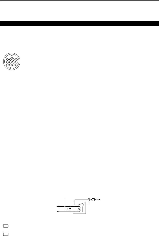
DDACC socket information
• ACC socket
|
|
ACC |
|
|
PIN No. |
NAME |
|
DESCRIPTION |
SPECIFICATIONS |
||||
|
|
|
|
|
|
1 |
8 V |
Regulated 8 V output. |
Output voltage: |
8 V ± 0.3 V |
|||
|
|
|
|
|
|
Output current: |
Less than 10 mA |
||||||
|
|
|
|
|
|
|
|
|
|
|
|||
|
|
|
|
|
|
|
|
|
|
|
|
||
|
|
|
|
|
|
2 |
GND |
Connects to ground. |
|
——— |
|||
9 |
10 |
11 |
12 |
|
|
|
|
|
An external equipment |
Input voltage (High): |
2.0 V to 20.0 V |
||
|
|
13 |
|
|
|
|
|
|
|
|
|
||
1 |
2 |
3 |
4 |
|
|
|
|
|
controls the transceiver. |
Input voltage (Low): |
–0.5 V to +0.8 V |
||
|
|
|
|
|
When this pin goes low, |
||||||||
5 |
6 |
7 |
8 |
|
|
|
|
|
|
|
|
||
|
|
|
|
|
|
3 |
HSEND |
Input/out- |
|
the transceiver transmits. |
Current flow: |
Maximum 20 mA |
|
|
|
|
|
|
|
|
*1, 2 |
put pin. |
|
|
|
|
|
Rear panel view |
|
|
The transceiver outputs |
Output voltage (Low): Less than 0.1 V |
|||||||||
q brown |
i gray |
|
|
|
|
a low signal to control |
Current flow: |
Maximum 200 mA |
|||||
w red |
|
o white |
|
|
|
|
external equipment. |
|
|
||||
|
4 |
BDT |
Data line for the optional AT-180. |
|
——— |
||||||||
e orange |
!0black |
|
|||||||||||
r yellow |
!1pink |
|
|
|
|
|
|
|
|||||
|
NC |
*3 If the modification is performed, |
|
——— |
|||||||||
t green |
!2light |
5 |
|
||||||||||
(BAND*3) |
band voltage output. (AI sec. 19) |
Output voltage: |
0 to 8 V |
||||||||||
y blue |
|
|
blue |
|
|||||||||
u purple |
!3light |
|
|
|
|
|
|
|
|||||
|
|
|
|
|
Control voltage: |
–4 V to 0 V |
|||||||
|
|
|
|
green |
6 |
ALC |
ALC voltage input. |
||||||
|
|
|
|
Input impedance: |
More than 3.3 k˘ |
||||||||
|
|
|
|
|
|
|
|
|
|
|
|||
|
|
|
|
|
|
|
|
|
|
|
|||
|
|
|
|
|
|
|
|
An external equipment |
|
|
|||
|
Color |
refers to |
|
|
|
|
|
Input voltage (High): |
2.0 V to 20.0 V |
||||
|
the cable strands |
|
|
|
|
|
controls the transceiver. |
Input voltage (Low): |
–0.5 V to +0.8 V |
||||
|
of the |
supplied |
|
|
|
|
|
When this pin goes low, |
|||||
|
cable. |
|
|
|
7 |
VSEND |
Input/out- |
|
the transceiver transmits. |
Current flow: |
Maximum 20 mA |
||
|
|
|
|
|
|
|
*1, 2 |
put pin. |
|
|
|
|
|
|
|
|
|
|
|
|
|
The transceiver outputs |
Output voltage (Low): Less than 0.1 V |
||||
|
|
|
|
|
|
|
|
|
|
a low signal to control |
Current flow: |
Maximum 200 mA |
|
|
|
|
|
|
|
|
|
|
|
external equipment. |
|
|
|
|
|
|
|
|
|
8 |
13.8 V |
13.8 V output when power is ON. |
Output current: |
Less than 1 A |
|||
|
|
|
|
|
|
9 |
TKEY |
Key line for the optional AT-180. |
|
——— |
|||
|
|
|
|
|
|
|
|
|
|
|
|
|
|
|
|
|
|
|
|
|
|
|
|
|
“High” level: |
More than 2.4 V |
|
|
|
|
|
|
|
10 |
FSKK |
Controls RTTY keying |
“Low” level: |
Less than 0.6 V |
|||
|
|
|
|
|
|
|
|
|
|
|
Output current: |
Less than 2 mA |
|
|
|
|
|
|
|
|
|
|
|
|
|
|
|
|
|
|
|
|
|
11 |
MOD |
Modulator input. |
Input impedance: |
10 k˘ |
|||
|
|
|
|
|
|
Input level: |
Approx. 100 mV rms |
||||||
|
|
|
|
|
|
|
|
|
|
|
|||
|
|
|
|
|
|
|
|
|
|
|
|||
|
|
|
|
|
|
12 |
AF*3 |
AF detector output. |
Output impedance: |
4.7 k˘ |
|||
|
|
|
|
|
|
Fixed level, regardless of the [AF] |
|||||||
|
|
|
|
|
|
|
|
control position. |
Output level: |
100 to 300 mV rms |
|||
|
|
|
|
|
|
|
|
|
|
||||
|
|
|
|
|
|
13 |
SQL S |
Squelch output. |
SQL open: |
Less than 0.3 V/5 mA |
|||
|
|
|
|
|
|
Grounded when squelch opens. |
SQL closed: |
More than 6.0 V/100 µA |
|||||
|
|
|
|
|
|
|
|
||||||
|
|
|
|
|
|
|
|
|
|
|
|
|
|
*1 When the SEND terminal controls the inductive load (such as a relay), a counter-electromotive force can cause the transceiver’s malfunction or damage. To prevent this, we recommend adding a switching diode, such as an “1SS133,” on the load side of the circuit to the counter-electromotive force absorption.
When the diode is added, a switching delay of the relay may occur. Be sure to check its switching action before operation.
[Example] |
Switching diode |
|
ACC socket |
To a non-Icom |
|
eHSEND or |
linear amplifier |
|
|
||
uVSEND |
Relay |
|
i13.8 V |
||
|
*2 VSEND is used for the 144 MHz and 430 MHz bands, and HSEND is used for the HF, 50/70 MHz bands by default. You can change this setting in “VSEND Select” of the “Connectors” Set mode. (p. 6-8)
SET > Connectors > VSEND Select
*3 You can change this setting in “ACC/USB Output Select” of the “Connectors” Set mode. (p. 6-8)
SET > Connectors > ACC/USB Output Select
1-16
• When connecting the ACC conversion cable (OPC-599)
!3 Connect to ACC socket o !0 !12!
t y u i q w e r
ACC 1 |
4 |
2 |
5 |
|
|
||
|
1 |
8 |
3 |
|
6 |
7 |
|
|
|
||
q FSKK |
|
t AF |
|
w GND |
|
|
y SQLS |
e HSEND |
|
u 13.8 V |
|
r MOD |
|
i ALC |
|
PANEL DESCRIPTION |
1 |
ACC 2 |
4 |
2 |
5 |
|
|
||
|
|
|
|
|
1 |
|
3 |
|
6 |
|
7 |
q 8 V |
|
t ALC |
|
w GND |
|
y VSEND |
|
e HSEND |
u 13.8 V |
||
r BAND |
|
||
DDDATA2 socket information
DATA2 |
|
PIN No. |
NAME |
DESCRIPTION |
SPECIFICATIONS |
||
|
|
1 |
DATA IN |
Input terminal for data transmit. |
Input level (1200 bps): |
100 mV |
|
|
|
(1200 bps: AFSK/ |
Input level (9600 bps): |
0.2 to 0.5 Vp-p |
|||
|
|
|
|
9600 bps: G3RUH, GMSK) |
|
|
|
q w |
|
2 |
GND |
Common ground for DATA IN, DATA |
——— |
||
|
OUT and AF OUT. |
||||||
e |
r |
|
|
|
|
||
|
|
PTT terminal for packet operation. |
Input voltage (High): |
2.0 V to 20.0 V |
|||
t y |
|
3 |
PTT |
||||
|
Connect to ground to activate the |
Input voltage (Low): |
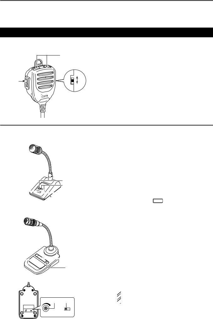
–0.5 V to +0.8 V |
||||
|
|
||||||
Rear panel view |
|
|
transmitter. |
|
|
||
4 |
DATA OUT |
Data out terminal for 9600 bps opera- |
Output impedance: |
10 k˘ |
|||
|
|
||||||
|
|
|
|
tion only. |
Output level: |
1.0 Vp-p |
|
|
|
5 |
AF OUT |
Data out terminal for 1200 bps opera- |
Output impedance: |
4.7 k˘ |
|
|
|
tion only. |
Output level: |
100–300 mV rms |
|||
|
|
|
|
||||
|
|
|
|
Squelch out terminal. This pin is |
SQL open: |
Less than 0.3 V/ |
|
|
|
|
|
grounded when the transceiver re- |
|
5 mA |
|
|
|
|
|
ceives a signal which opens the |
SQL closed: |
More than 6.0 V/ |
|
|
|
6 |
SQL |
squelch. |
|
100 µA |
|
|
|
• To avoid interfering transmissions, |
|
|
|||
|
|
|
|
connect squelch to the TNC to inhibit |
|
|
|
|
|
|
|
transmission when squelch is open. |
|
|
|
|
|
|
|
• Keep RF gain at a normal level, other- |
|
|
|
|
|
|
|
wise a “SQL” signal will not be output. |
|
|
|
DDMicrophone connector information
|
|
|
|
|
MIC |
PIN No. |
NAME |
DESCRIPTION |
SPECIFICATIONS |
||||||||||
|
|
|
|
|
|
|
|
|
|
|
|
|
|
|
|
1 |
8 V |
+8 V DC output. |
Maximum 10 mA |
|
|
|
|
|
|
|
|
|
|
|
|
|
|
|
|
|
|
|
|
|
|
|
|
|
|
|
|
|
|
|
|
|
|
|
|
2 |
MIC U/D |
Frequency Up/Down |
UP: Ground |
|
|
|
|
|
|
|
|
|
|
|
|
|
|
|
|
DN: Ground through 470 ˘ |
|||
|
|
|
|
|
|
|
|
|
|
|
|
|
|
|
|
|
|
|
|
|
|
|
|
|
|
|
|
|
|
|
|
|
|
|
|
3 |
M8V SW |
HM-151 connection |
|
|
|
|
|
|
|
|
|
|
|
|
|
|
|
|
|
Ground to indicate the HM-151 is connected. |
— |
||
|
|
|
|
|
|
|
|
|
|
|
|
|
|
|
|
||||
|
|
|
|
|
|
|
|
|
|
|
|
|
|
|
|
|
|
When the HM-151 is not connected; outputs an AF.*1 |
|
|
|
|
|
|
|
|
|
|
|
|
|
|
|
|
|
|
|
|
|
|
|
|
|
|
|
|
|
|
|
|
|
|
|
|
|
4 |
PTT |
PTT input |
— |
|
|
|
|
|
|
|
|
|
|
|
|
|
|
|
|
||||
87654321 |
|
|
|
|
|||||||||||||||
Rear panel view |
5 |
MIC E |
Microphone ground |
— |
|||||||||||||||
|
|
|
|
||||||||||||||||
|
|
|
|
|
|
|
|
|
|
|
|
|
|
|
|
6 |
MIC |
Microphone input |
— |
|
|
|
|
|
|
|
|
|
|
|
|
|
|
|
|
|
|
|
|
|
|
|
|
|
|
|
|
|
|
|
|
|
|
|
|
7 |
GND |
Ground |
— |
|
|
|
|
|
|
|
|
|
|
|
|
|
|
|
|
|
DATA IN |
When the HM-151 is connected; HM-151 data input |
— |
|
|
|
|
|
|
|
|
|
|
|
|
|
|
|
|
8 |
|
|
|
|
|
|
|
|
|
|
|
|
|
|
|
|
|
|
|
SQL SW |
When the HM-151 is not connected; Squelch switch |
Open: ‘Low’ level |
|
|
|
|
|
|
|
|
|
|
|
|
|
|
|
|
|
|
Close: ‘High’ level |
||
|
|
|
|
|
|
|
|
|
|
|
|
|
|
|
|
|
|
|
|
*1 You can change this setting in “MIC AF Out” of the “Function” Set mode. (p. 6-6)
SET > Function > MIC AF Out
1-17
1 PANEL DESCRIPTION
Microphone
DDHM-198 (Supplied)
|
w |
|
ON |
q |
e |
|
OFF |
qPTT SWITCH
Hold down to transmit, release to receive.
wUP/DOWN KEYS [UP]/[DN]
Push either key to change the operating frequency, memory channel, Set mode setting, and so on. (p. 3-9, AI sec. 4, 11)
Hold down either key for 1 second to start scanning.
eUP/DN LOCK SWITCH
Slide to turn the [UP]/[DN] keys lock function ON or OFF.
The optional OPC-589 cable is required to connect these 8-pin microphones.
DDSM-50 (Option)
r |
e |
q
 w
w  y
y
DDSM-30 (Option)
TOP VIEW
q
 w
w
t
BOTTOM VIEW
y |
r |
|
OFF ON |
MIC GAIN |
LOW CUT |
qPTT SWITCH
Hold down to transmit, release to receive.
wPTT LOCK SWITCH
Push to lock the PTT switch in the transmit mode.
eUP/DOWN SWITCHES [UP]/[DN]
Change the selected readout frequency or memory channel.
•Holding down continuously changes the frequency or memory channel number.
•While holding down XFC , the transmit readout frequency can be controlled while in the split frequency mode.
•The [UP]/[DN] switch can simulate a key paddle.Preset in the “KEYER SET” mode (U/D KEY; MIC Up/Down Keyer). (AI sec. 4)
rLOW CUT SWITCH
Push (SM-50)/Slide (SM-30) to cut out the low frequency components of input voice signals.
tPTT LOCK INDICATOR [LOCK]
(Only for the SM-30)
Lights red when the PTT lock switch (w) is ON.
yMIC GAIN VOLUME [MIC GAIN]
Rotate to adjust the microphone output level.
•Use this control as an addition to the microphone gain setting of the connected transceiver.
 Rotating the control too far clockwise may result
 in an output level that is too high and transmit sig-
  nal distortion.
1-18
PANEL DESCRIPTION |
1 |
DDHM-151 (Option)
q w

e r
t
SPCH |
TUNER |
XFC |
|
/LOCK |
/CALL |
||
|
|
|
V/M |
|
MW |
|
|
|
|
|
|
|
F-1 |
|
F-2 |
|
|
|
|
|
1.8 1 |
3.5 2 |
7 |
3 |
MODE |
10 4 |
14 5 |
18 6 |
FIL |
21 7 |
24 8 |
28 9 |
GENE |
|
50 |
. |
144 |
430 |
F-INP |
|
0 |
CE |
ENT |
|
Mic element
y
qSPCH/LOCK KEY [SPCH/LOCK]
SPEECH KEY Operation (p. 3-20)
Push to audibly announce the S-meter level, the displayed frequency and the operating mode.
• The S-Level announcement can be turned OFF in the
“S-Level SPEECH” item of the “SPEECH” Set mode. (p. 6-4)
SET > SPEECH > S-Level SPEECH
•When RIT is ON, the RIT offset is not included in the frequency announcement.
LOCK KEY Operation (AI sec. 5)
Hold down for 1 second to turn the Lock function ON or OFF.
•The function electronically locks the Dial.
•“ ” appears when the function is ON.
• You can select the Dial lock and Panel lock in the
“Lock Function” item of the “Function” Set mode (p. 6-6).
SET > Function > Lock Function
wPTT SWITCH [PTT] (p. 3-23)
Hold down to transmit, release to receive.
eUP/DOWN KEYS [Y]/[Z]
Change the operating frequency.
•Hold down to continuously change the frequency.
•If the Quick tuning icon is not displayed, the tuning step is 50 Hz.
rTRANSMIT LED
Lights red while transmitting.
tKEYPAD
Pushing a key selects the operating band.
•[(GENE)•] selects the general coverage band.
Pushing the same key 2 or 3 times calls up other stacked frequencies in the band.
•Icom’s triple band stacking register memorizes 3 frequencies in each band.
After pushing [(F-INP)ENT], enter a numeric frequency, then press [(F-INP)ENT] again.
•Example: To enter 14.195 MHz, push [(F-INP)ENT] [1] [4] [•] [1] [9] [5] [(F-INP)ENT].
yFILTER SELECTION KEY [FIL]
Push to select one of three IF filter settings.
•The selected filter passband width and shifting value are displayed for 2 seconds in the window.
Push for 1 second to display the “FILTER” screen to adjust the filter passband width.
When the “FILTER” screen is displayed, push for 1 second to return to the previous screen.
1-19

1 PANEL DESCRIPTION
Microphone
DDHM-151 (Option) (Continued)
!3
SPCH |
TUNER |
XFC |
|
/LOCK |
/CALL |
||
|
|
|
V/M |
|
MW |
|
|
|
|
|
|
|
F-1 |
|
F-2 |
|
|
|
|
|
1.8 1 |
3.5 2 |
7 |
3 |
MODE |
10 4 |
14 5 |
18 6 |
FIL |
!2
!1
!0 o
i Mic element u
21 7 |
24 8 |
28 9 |
GENE |
|
50 |
. |
144 |
430 |
F-INP |
|
0 |
CE |
ENT |
|
uMODE KEY [MODE]
Push to cycle through the operating modes: USB/LSB CW/CW-R RTTY/RTTY-R AMFM WFM DV
Hold down for 1 second to toggle the following operating modes:
USB LSB
CW CW-R
RTTY RTTY-R
iPOWER LED
Lights green when transceiver’s power is ON.
oPROGRAMMABLE FUNCTION KEYS [F-1]/[F-2]
Program and perform a selected function.
• The functions can be assigned in the “RC MIC” item of the “Function” Set mode (p. 6-6). The default settings for [F-1] and [F-2] are “MPW” and “MPR.”
SET > Function > RC MIC
!0MEMORY WRITE KEY [MW] (AI sec. 11)
Hold down for 1 second to store VFO data into the selected memory channel.
• This can be done in both the VFO and memory modes.
!1VFO/MEMORY SELECTION KEY [V/M]
Push to switch between the VFO and memory modes. (p. 3-4)
Hold down for 1 second to copy the memory contents to the displayed VFO. (AI sec. 11)
!2TRANSMIT FREQUENCY CHECK KEY [XFC]
During split frequency or repeater operation, hold down to listen to the transmit frequency. (AI sec. 4)
• While holding down this switch, the transmit frequency can be changed with the Dial or MPAD .
• When the Split Lock function is turned ON in the Split operation, hold down [XFC] to cancel the Dial lock function. (AI sec. 6)
When operating simplex, hold down to monitor the frequency.
• While holding down this key, the squelch is open and the interference reject function is temporarily turned OFF.
When operating simplex and the RIT function is turned ON, hold down to listen to the transmit frequency. The frequency is the same as when the RIT is OFF. (AI sec. 5)
In the DV mode, hold down this key to select the RX monitoring mode. (p. 6-3)
!3TUNER/CALL KEY [TUNER/CALL]
ANTENNA TUNER KEY Operation (AI sec. 16)
(Frequency band: HF, 50/70* MHz)
Push to turn an optional antenna tuner ON or OFF (bypass).
Hold down for 1 second to manually start the antenna tuner.
• If the tuner cannot tune the antenna within 20 seconds, the tuning circuit is automatically bypassed.
*70 MHz band transmission is available, depending on the transceiver version.
CALL KEY Operation (AI sec. 11)
(Frequency band: 144/430 MHz)
Push to select the Call channel.
1-20

Section 2 |
INSTALLATION AND CONNECTIONS |
|
|
Selecting a location................................................................. |
2-2 |
|
Grounding................................................................................. |
2-2 |
|
Antenna connection................................................................. |
2-2 |
|
Connect controller to transceiver........................................... |
2-3 |
|
DDThe Main unit installation......................................................... |
2-3 |
|
Connect to the controller........................................................ |
2-4 |
|
Required Connections to a Transceiver................................. |
2-5 |
|
The External Units Connections to a Transceiver................. |
2-6 |
|
Power Supply Connections..................................................... |
2-7 |
|
DDConnecting the PS-126 power supply...................................... |
2-7 |
|
DDConnecting a non-Icom DC power supply............................... |
2-7 |
|
Linear Amplifier Connections................................................. |
2-8 |
|
DDConnecting the IC-PW1/EURO................................................ |
2-8 |
|
DDConnecting a non-Icom linear amplifier................................... |
2-8 |
Section 1 panel description
Section 2 INSTALLATION AND CONNECTIONS
Section 3 BASIC OPERATION
Section 4 D-STAR INTRODUCTION
Section 5 D-STAR OPERATION <BASIC>
Section 6 SET MODE
Section 7 INSTALLATION NOTES
“AI” means “Advanced Instructions.” “sec. MM” means section number.
So when “(AI sec. MM)” is described on this manual, see the PDF type
Advanced Instruction’s section number for your reference.
2-1
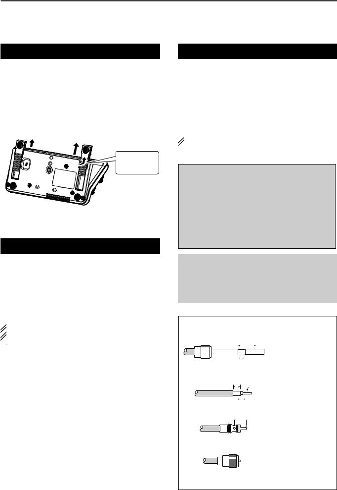
2 INSTALLATION AND CONNECTIONS
Selecting a location
Select a location for the transceiver that allows adequate air circulation, free from extreme heat, cold, vibrations, away from TV sets, TV antenna elements, radios and other electromagnetic sources.
The base of the transceiver has adjustable feet for desktop use. Set the feet to one of two angles, to meet your operating preference.
Slide in the direction of arrow.
Controller bottom view
Grounding
To prevent electrical shock, television interference (TVI), broadcast interference (BCI) and other problems, ground the transceiver using the GROUND terminal on the rear panel.
For best results, connect a heaviest gauge wire or strap to a long ground rod. Make the distance between the [GND] terminal and ground as short as possible.
 R WARNING! NEVER connect the [GND] ter-
  minal to a gas or electric pipe, since the connection
  could cause an explosion or electric shock.
Antenna connection
For radio communications, the antenna is of critical importance, along with output power and receiver sensitivity. Select a well-matched 50 ø antenna and coaxial cable feedline.We recommend 1.5:1 or better of Voltage Standing Wave Ratio (VSWR) on your operating bands. The transmission line should be a coaxial cable.
When using a single antenna (for the HF, 50/70 MHz bands), use the [ANT1] connector.
 CAUTION: Protect your transceiver from lightning by
  using a lightning arrestor.
Antenna SWR
Each antenna is tuned for a specified frequency range and the SWR usually increases outside the range. When the SWR is higher than approximately 2.0:1, the transceiver automatically reduces the TX power to protect the final transistors. In that case, an antenna tuner is useful to match the transceiver and antenna. Low SWR allows full power for transmitting. The IC-7100 has an SWR meter to continuously monitor the antenna SWR.
Antenna connection
Connect the cable from an HF, 50/70 MHz antenna to the [ANT 1] connector.
Connect the cable from a 144/430MHz antenna to the [ANT 2] connector.
PL-259 CONNECTOR INSTALLATION EXAMPLE
q
|
|
|
|
|
|
30 mm |
|
|
|||
|
|
|
|
|
|
|
|||||
|
|
|
|
|
|
|
|
|
|
|
|
|
|
|
|
|
|
|
|
|
|
|
|
|
|
|
|
|
|
|
|
|
|
|
|
|
|
|
|
|
|
|
|
|
|
|
|
|
|
|
|
|
|
|
|
|
|
|
|
Coupling ring |
10 mm (Tin) |
||||||||||
w |
10 mm Tin |
||||||||||
|
|
|
|
||||||||
|
|
|
|
|
|
|
|
|
|
|
|
|
|
|
|
|
|
|
|
|
|
|
|
|
|
|
|
|
|
|
|
|
|
|
|
|
|
|
|
|
|
|
|
|
|||
|
|
|
|
|
1–2 |
|
mm |
||||
Slide the coupling ring down. Strip the cable jacket and tin the shield.
Strip the cable as shown at the left. Tin the center conductor.
e
solder solder
Slide the connector body on and solder it.
r
Screw the coupling ring onto the connector body.
(30 mm 9⁄8 in 10 mm 3⁄8 in 1–2 mm 1⁄16 in)
2-2
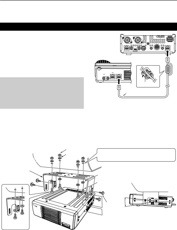
INSTALLATION AND CONNECTIONS 2
Connect controller to transceiver
The Main unit becomes hot when transmitted for long period of time.
DO NOT place anything on the transceiver. It may obstruct radiation and cause mechanical trouble.
Using Ferrite EMI filter*
Depending on the installed condition of the transceiver, malfunction may occur by the wraparound of the electric wave. This problem can be resolved by using the Ferrite EMI filter.
*The filter connection is required for the European versions.
Rear panel
Controller |
To the [CONTROLLER] |
|
connector |
To the [MAIN UNIT] |
Ferrite EMI filter |
|
|
connector |
Controller cable |
|
DDThe Main unit installation
Nut
Spring washer
MB-62
Main unit installation
Drill 5 mm holes for the bracket location.
Drill 3 mm holes for the tapping screws.
Flat washer |
The MB-62 can be used for AT-180 as well. |
|
|
Screw |
Adjust for the best viewing angle. |
|
Frange bolt
Using
tapping screws
IC-7100
2-3

2 INSTALLATION AND CONNECTIONS
Connecting accessories to the controller
[MIC] Connector |
|
|
HM-151 |
HM-198 |
Adapter cable Microphone |
OPC-589
HM-36 SM-50
Do not connect 2 microphones at same time. Both microphone have transmission if they are connected to controller and transceiver.
CAUTION: NEVER connect or use the optional HM-151 (microphone) with any other transceiver. This could damage the transceiver. The HM-151 is designed to use with the IC-7000/ IC-7100 series ONLY.
Controller
• External Keypad
Control the CW memory keyer transmission from external keypad by connecting control circuit to MIC connector.
Set the “Keyer” item in the “Connectors” Set mode to “ON,” to use
external keypad. (AI sec. 17)
• Data transmission (AFSK)
Connect TNC (Terminal Node Controller) to [MIC] connector to enable data transmission AFSK). (AI sec 18)
Connect to the [CONTROLLER] connector of the Main unit
[PHONES/SP] Headphone/External Speaker Jack
Set the switch under con- External spaeaker troller to “PHONES” to use
headphone and set “SP” to use speaker.
Bottom of the |
SP-35 (optional) |
|
controller |
||
|
The transceiver accepts headphones with maximum 5 mW in to an 8 Ω impedance.
The sound level may differ, depending on the headphones.
3.5(d) mm/1⁄8˝ plug Headphone
[ELEC-KEY] Electronic keyer Jack
A jack to connect the paddle
with electrode control on the end terminal.
dash Connect to the [KEY] Jack of the Main unit when using an Electric keyer. p. 2-5)
dot |
Set internal keyer in de- |
|
fault but it can be changed |
||
com |
||
3.5(d) mm/1⁄8˝ plug |
by the “Keyer” Set mode |
|
|
(AI sec. 4) |
2-4
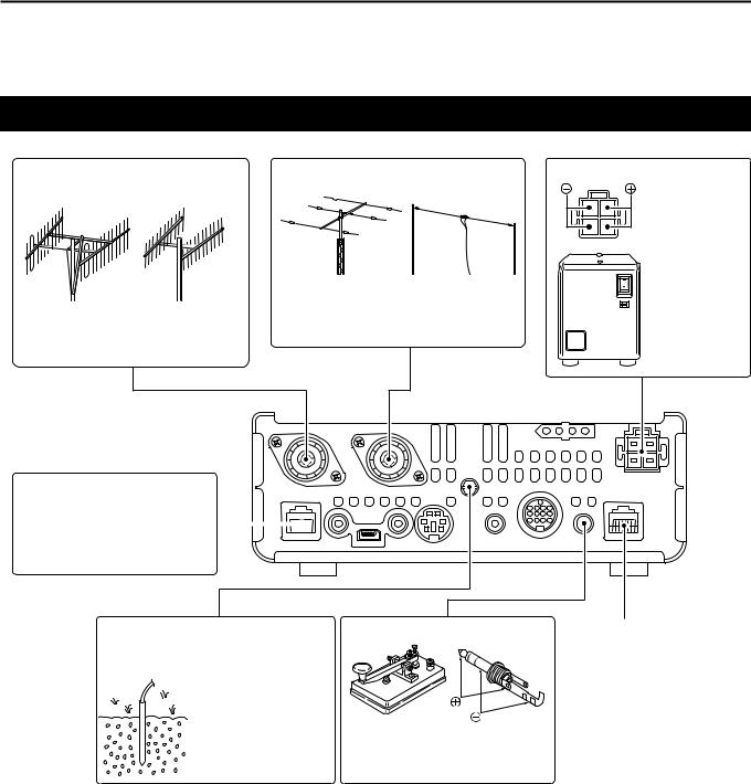
INSTALLATION AND CONNECTIONS 2
Required Connections to a Transceiver
[ANT2] 144/430MHz BANDS |
[ANT1] HF, 50/70 MHz BANDS |
CONNECTOR (p. 2-2) |
CONNECTOR (P. 2-3) |
|
Connect a 50 Ω antenna for the |
|
Connect a 50 Ω antenna for the |
HF, 50/70 MHz frequency bands or |
|
below 74.8 MHz. |
||
144/430 MHz frequency bands or |
||
|
||
74.8 MHz and above. |
|
|
IC-7100 |
|
[DC 13.8V] DC POWER SUPPLY
(P. 2-7)
Use a power
supply with 13.8 V DC
output and a
capacity of at least 22 Amperes.
PS-126 (Optional)
[MIC] MODULAR MICROPHONE CONNECTOR (p. 2-4)
As with a microphone connec- 


 tor of the controller, accepts
the supplied microphone.
[GND] GROUND TERMINAL (p. 2-2)
Connect this terminal to a station or vehicle ground to prevent electrical shocks, TVI, BCI and other problems.
STRAIGHT KEY JACK
Plug diameter: 3.5 mm/1⁄8˝
Accepts a straight key or an external electronic keyer.
Connect to the [MAIN UNIT] connector of the Controller. (p. 2-4)
2-5
Loading...