


INSTRUCTION MANUAL
VHF/UHF FM TRANSCEIVER
i208H
This device complies with Part 15 of the FCC rules. Operation is subject to the following two conditions: (1) This device may not cause harmful interference, and (2) this device must accept any interference received, including interference that may cause undesired operation.
FOREWORD
Thank you for purchasing this Icom product. The IC-208H VHF/UHF FM TRANSCEIVER is designed and built with Icom’s state of the art technology and craftsmanship. With proper care, this product should provide you with years of trouble-free operation.
We want to take a couple of moments of your time to thank you for making your IC-208H your radio of choice, and hope you agree with Icom’s philosophy of “technology first.” Many hours of research and development went into the design of your IC-208H.
DFEATURES
Switchable VHF and UHF transceiver
Selectable backlit color from amber, green and yellow
Detachable controller for flexible installation
55 W* of high transmit output power
*VHF band; 50 W for UHF and Korean version, 25 W for Taiwan version
Remote control microphone standard
New DMS (Dynamic Memory Scan) system
IMPORTANT
READ ALL INSTRUCTIONS carefully and completely before using the transceiver.
SAVE THIS INSTRUCTION MANUAL— This instruction manual contains important operating instructions for the IC-208H.
EXPLICIT DEFINITIONS
WORD |
DEFINITION |
Personal injury, fire hazard or electric shock RWARNING! may occur.
CAUTION Equipment damage may occur.
NOTE
Recommended for optimum use. No risk of personal injury, fire or electric shock.
Icom, Icom Inc. and the 
 logo are registered trademarks of Icom Incorporated (Japan) in the United States, the United Kingdom, Germany, France, Spain, Russia and/or other countries.
i

PRECAUTION
RWARNING RF EXPOSURE! This device emits Radio Frequency (RF) energy. Extreme caution should be observed when operating this device. If you have any questions regarding RF exposure and safety standards please refer to the Federal Communications Commission Office of Engineering and Technology’s report on Evaluating Compliance with FCC Guidelines for Human Radio frequency Electromagnetic Fields (OET Bulletin 65).
RWARNING! NEVER connect the transceiver to an AC outlet. This may pose a fire hazard or result in an electric shock.
RWARNING! NEVER operate the transceiver while driving a vehicle. Safe driving requires your full attention—anything less may result in an accident.
NEVER connect the transceiver to a power source of more than 16 V DC. This will damage the transceiver.
NEVER connect the transceiver to a power source using reverse polarity. This will damage the transceiver.
NEVER cut the DC power cable between the DC plug and fuse holder. If an incorrect connection is made after cutting, the transceiver may be damaged.
NEVER expose the transceiver to rain, snow or any liquids. The transceiver may be damaged.
NEVER operate or touch the transceiver with wet hands. This may result in an electric shock or damage the transceiver.
NEVER place the transceiver where normal operation of the vehicle may be hindered or where it could cause bodily injury.
NEVER let objects impede the operation of the cooling fan on the rear panel.
DO NOT push the PTT when not actually desiring to transmit.
DO NOT allow children to play with any radio equipment containing a transmitter.
During mobile operation, DO NOT operate the transceiver without running the vehicle’s engine. When the transceiver’s power is ON and your vehicle’s engine is OFF, the vehicle’s battery will soon become exhausted.
AVOID using or placing the transceiver in direct sunlight or in areas with temperatures below –10°C (+14°F) or above +60°C (+140°F).
BE CAREFUL! The transceiver will become hot when operating it continuously for long periods.
AVOID setting the transceiver in a place without adequate ventilation. Heat dissipation may be affected, and the transceiver may be damaged.
AVOID the use of chemical agents such as benzine or alcohol when cleaning, as they can damage the transceiver’s surfaces.
USE Icom microphones only (supplied or optional). Other manufacturer’s microphones have different pin assignments and may damage the transceiver if attached.
For U.S.A. only
CAUTION: Changes or modifications to this device, not expressly approved by Icom Inc., could void your authority to
operate this device under FCC regulations.
ii
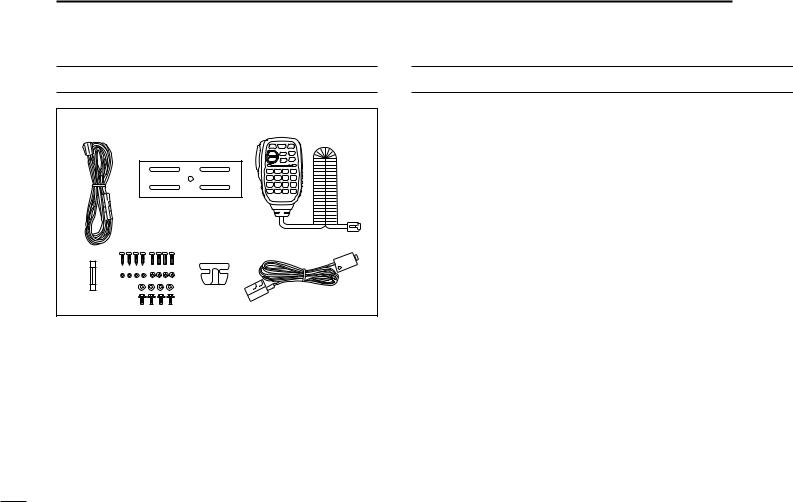
SUPPLIED ACCESSORIES
|
q |
|
e |
|
|
w |
|
|
t |
y |
u |
r |
|
||
|
|
|
q DC power cable (3 m) ………………………………………1
w Mobile mounting bracket …………………………………1
e Microphone (HM-133)* ……………………………………1
r Fuse (20 A) …………………………………………………1
t Mounting screws, nuts and washers …………………1 set y Microphone hanger …………………………………………1
u Separation cable† (3.5 m; 11.5 ft) …………………………1
*HM-118N HAND MICROPHONE or HM-118TN/TAN DTMF MICROPHONE
supplied versions are also available.
†A ferrite core is adapted for the USA version.
TABLE OF CONTENTS |
|
|
FOREWORD ........................................................................................... |
i |
|
IMPORTANT ............................................................................................ |
i |
|
EXPLICIT DEFINITIONS ......................................................................... |
i |
|
PRECAUTION ........................................................................................ |
ii |
|
SUPPLIED ACCESSORIES .................................................................. |
iii |
|
TABLE OF CONTENTS ......................................................................... |
iii |
|
QUICK REFERENCE GUIDE ............................................................. |
I–X |
|
|
■ Installation ....................................................................................... |
I |
|
■ Your first contact .......................................................................... |
VII |
|
■ Repeater operation ....................................................................... |
IX |
|
■ Programming memory channels..................................................... |
X |
1 |
PANEL DESCRIPTION ............................................................... |
1–10 |
|
■ Front panel— controller ................................................................. |
1 |
|
■ Function display ............................................................................. |
3 |
|
■ Rear panel ..................................................................................... |
5 |
|
■ Microphone (HM-133) .................................................................... |
7 |
|
■ Microphone keypad ........................................................................ |
8 |
|
■ Optional microphones (HM-118N/TN/TAN)................................... |
10 |
2 |
SETTING A FREQUENCY ........................................................ |
11–14 |
|
■ Preparation ................................................................................... |
11 |
|
■ Using the tuning dial .................................................................... |
12 |
|
■ Using the [Y]/[Z] keys ................................................................. |
12 |
|
■ Using the keypad ......................................................................... |
12 |
|
■ Tuning step selection ................................................................... |
13 |
|
■ Lock functions .............................................................................. |
14 |
3 |
BASIC OPERATION ................................................................. |
15–18 |
|
■ Receiving ..................................................................................... |
15 |
|
■ Monitor function ........................................................................... |
15 |
|
■ Squelch attenuator ....................................................................... |
16 |
|
■ Transmitting ................................................................................. |
17 |
|
■ Selecting output power ................................................................ |
17 |
iii

|
■ One-touch PTT function ............................................................... |
18 |
|
■ Audio mute function ..................................................................... |
18 |
4 |
REPEATER OPERATION ......................................................... |
19–25 |
|
■ General ........................................................................................ |
19 |
|
■ Accessing a repeater ................................................................... |
20 |
|
■ Subaudible tones ......................................................................... |
22 |
|
■ Offset frequency .......................................................................... |
24 |
|
■ Auto repeater (USA version only) ................................................ |
25 |
5 |
MEMORY OPERATION ............................................................ |
26–37 |
|
■ General description ...................................................................... |
26 |
|
■ Memory channel selection ........................................................... |
26 |
|
■ Programming a memory channel ................................................. |
27 |
|
■ Copying memory contents ........................................................... |
29 |
|
■ Programming channel names ..................................................... |
31 |
|
■ Memory clearing .......................................................................... |
34 |
|
■ Memory bank selection ................................................................ |
35 |
|
■ Memory bank setting .................................................................... |
36 |
|
■ Transferring bank contents .......................................................... |
37 |
6 |
CALL CHANNEL OPERATION ................................................ |
38–39 |
|
■ Call channel selection .................................................................. |
38 |
|
■ Call channel transferring .............................................................. |
38 |
|
■ Programming a call channel ........................................................ |
39 |
7 |
SCAN OPERATION .................................................................. |
40–45 |
|
■ Scan types ................................................................................... |
40 |
|
■ Scan start/stop ............................................................................. |
41 |
|
■ Scan edges programming ............................................................ |
42 |
|
■ Skip channel setting ..................................................................... |
44 |
|
■ Scan resume condition ................................................................ |
45 |
8 |
PRIORITY WATCH .................................................................... |
46–47 |
|
■ Priority watch types ...................................................................... |
46 |
|
■ Priority watch operation ............................................................... |
47 |
9 DTMF MEMORY ENCODER ..................................................... |
48–51 |
■ Programming a DTMF code ......................................................... |
48 |
■ Transmitting a DTMF code .......................................................... |
50 |
■ DTMF speed ................................................................................ |
51 |
10 POCKET BEEP AND TONE SQUELCH ................................... |
52–55 |
■ Pocket beep operation ................................................................. |
52 |
■ Tone/DTCS squelch operation ..................................................... |
54 |
■ Tone scan ..................................................................................... |
55 |
11 OTHER FUNCTIONS ................................................................ |
56–74 |
■ Set mode ...................................................................................... |
56 |
■ Initial set mode ............................................................................. |
61 |
■ AM/FM narrow mode ................................................................... |
65 |
■ Weather channel operation (USA version only) ........................... |
66 |
■ Microphone keys .......................................................................... |
67 |
■ Partial reset .................................................................................. |
68 |
■ All reset ........................................................................................ |
68 |
■ Data cloning ................................................................................. |
69 |
■ Packet operation .......................................................................... |
71 |
12 MAINTENANCE ........................................................................ |
75–76 |
■ Troubleshooting ........................................................................... |
75 |
■ Fuse replacement ........................................................................ |
76 |
13 SPECIFICATIONS AND OPTIONS ........................................... |
77–78 |
■ Specifications ............................................................................... |
77 |
■ Options ......................................................................................... |
78 |
14 MODE ARRANGEMENT ........................................................... |
79–80 |
1
2
3
4
5
6
7
8
9
10
11
12
13
14
iv
QUICK REFERENCE GUIDE
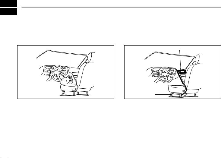
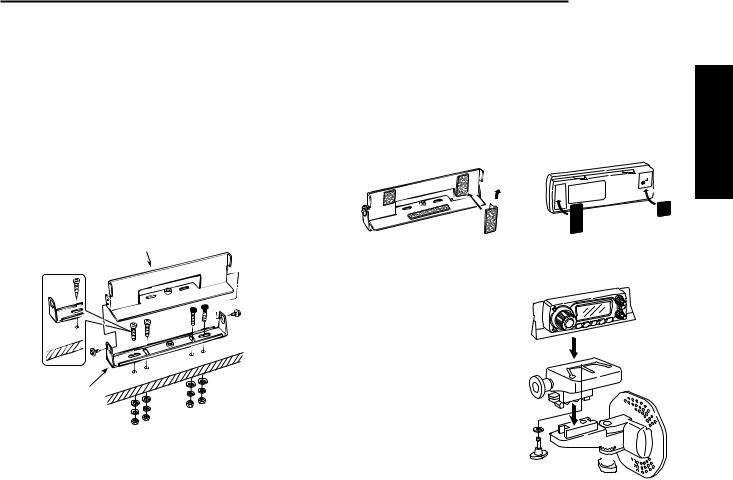
■ Installation
DInstallation methods
• Single body installation |
• Remote installation |
Transceiver |
Front panel |
|
Main unit
•The supplied mounting bracket (or optional MB-17A) can be used for the main unit installation.
I
•The supplied OPC-600/R SEPARATION CABLE can be used for remote installation.
•Optional OPC-601/R SEPARATION CABLE (7 m; 23 ft) is available for extend installation.
•Optional MB-58 REMOTE CONTROLLER BRACKET and MB-65
MOUNTING BASE are available for increasing front panel mounting possibilities.
•Optional OPC-440 MICROPHONE CABLE (5.0 m; 16.4 ft) and OPC-647 (2.5 m; 8.2 ft) are available to extend the microphone cable.
•Optional OPC-441 SPEAKER CABLE (5.0 m; 16.4 ft) is available to extend the speaker cable.
DLocation
Select a location which can support the weight of the transceiver and does not interfere with driving. We recommend the locations shown in the diagram below.
NEVER place the transceiver or remote controller where normal operation of the vehicle may be hindered or where it could cause bodily injury.
NEVER place the transceiver or remote controller where air bag deployment may be obstructed.
DO NOT place the transceiver or remote controller where hot or cold air blows directly onto it.
AVOID placing the transceiver or remote controller in direct sunlight.
 Main unit
Controller |
Main unit |
|
Main unit |
QUICK REFERENCE GUIDE
DUsing the mounting bracket
qDrill 4 holes where the mounting bracket is to be installed.
•Approx. 5.5–6 mm (1⁄4″) when using nuts; approx. 2–3 mm (1⁄8″) when using self-tapping screws.
wInsert the supplied screws, nuts and washers through the mounting bracket and tighten.
eAdjust the angle for your suitable position.
Nut
Spring washer
 Mounting
bracket
Mounting nut
Flat washer
When using self-tapping screws 25˚ 
Quick reference guide
II

QUICK REFERENCE GUIDE
DMicrophone connection
Connect the supplied microphone as illustrated below.
DSeparation cable connection
Using the supplied separation cable (3.5 m; 11.5 ft) or the optional separation cable (7 m; 23 ft) the controller can be separated from the main unit, doubling as a remote controller.
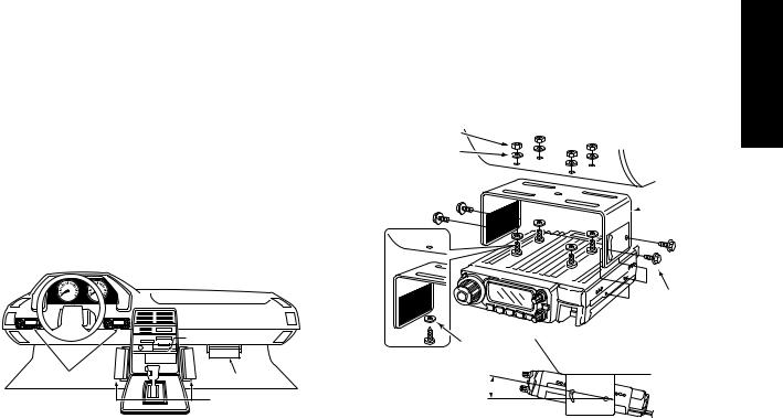
qDetach the controller as below.
q
Release latch |
w |
e
wConnect a separation cable between the controller and main unit using the supplied screws as illustrated below.
• Controller’s rear panel |
|
|
• Main unit |
|
|
|
|
|
|
||||
|
|
|
|
|
|
|
|
|
|
|
|
|
|
|
|
|
|
|
|
|
|
|
|
|
|
|
|
|
|
|
|
|
|
|
|
|
|
|
|
|
|
|
|
|
|
|
|
|
|
|
|
|
|
|
|
|
|
|
|
|
|
|
|
|
|
|
|
|
|
OPC-600/R or OPC-601/R
A ferrite core is adapted for the USA version.
 CAUTION!
NEVER short the terminals of the separation connector.  The 13.8 V power line is available in the connector, so the
  transceiver may damage when short circuited.


 NEVER short the terminals
III
DOptional MB-58 installation
The optional MB-58 REMOTE CONTROLLER BRACKET is available for separate installation.
qDrill 2 or 4 holes where the bracket is to be installed.
•Approx. 4 mm (1⁄8″) when using nuts; approx. 1–2 mm (1⁄16″) when using self-tapping screws.
wInsert the supplied screws, bolts and washers through the mounting base and tighten.
eAdjust the angle for the clearest view of the function display and tighten 2 screws when the mounting base is used.
When using self- |
Bracket |
|
|
tapping screws. |
|
Mounting 

 bolt
bolt
Mounting base
QUICK REFERENCE GUIDE
rAttach the supplied Velcro pads (large) to the remote controller and bracket.
tAttach the supplied Velcro pads (small) or rubber pad to the bracket as shown below; then attach the remote controller.
MB-58 |
IC-208H remote controller |
• When using the optional MB-65
MB-58 
Adjust the viewing angle for maximum visibility of the
function display.
MB-65
Quick reference guide
IV
QUICK REFERENCE GUIDE
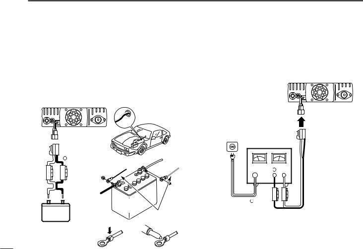
DBattery connection
RWARNING NEVER remove the fuse holders from the DC power cable.
NEVER connect the transceiver directly to a 24 V battery.
DO NOT use the cigarette lighter socket for power connections. (See p. 5 for details)
Attach a rubber grommet when passing the DC power cable through a metal plate to prevent a short circuit.
• CONNECTING TO A DC POWER SOURCE
Grommet
DDC power supply connection
Use a 13.8 V DC power supply with at least 15 A capacity.
Make sure the ground terminal of the DC power supply is grounded.
• CONNECTING TO A DC POWER SUPPLY
IC-208H
|
IC-208H |
|
|
DC power |
|
|
|
|
|
|
|
|
|
|
|
|
|
|
supply 13.8 V |
|
red |
− black |
+red |
to an |
|
|
|
|
|
|
|
|
||
|
|
Fuses |
_black |
AC |
− |
|
|
|
|
||||
|
|
20 A |
|
outlet |
|
|
|
|
|
|
|
|
|
|
|
WARNING! |
|
|
|
Fuses |
|
|
12 V |
|
− black |
20 A |
|
12 V |
NEVER |
battery |
|
red |
|
|
remove the |
|
|
|
|||
Supplied |
|
|
|
|||
fuse holders. |
|
|
|
|||
|
|
DC power cable |
See p. 76 for fuse replacement. |
|||
|
|
|
||||
NOTE: |
Crimp |
Solder |
|
|
|
Use terminals for the |
|
|
cable connections. |
|
|
V
DAntenna installation
• Antenna location
To obtain maximum performance from the transceiver, select a high-quality antenna and mount it in a good location. A nonradial antenna should be used when using a magnetic mount.
Trunk-mount Roof-mount antenna antenna (Drill a hole or use a magnetic mount.)
Gutter-mount antenna 
To antenna
QUICK REFERENCE GUIDE
• Antenna connector
The antenna uses a PL-259 connector.
• PL-259 CONNECTOR |
|
|
|
|||||||||
|
|
|
|
30 mm |
|
|
q Slide |
the coupling |
ring |
|||
|
|
|
|
|
||||||||
|
|
|
|
|
|
|
|
|
|
down. |
Strip the |
cable |
|
|
|
|
|
|
|
|
|
|
|||
|
|
|
|
|
|
|
|
|
|
|||
|
|
|
|
|
|
|
|
|
|
jacket and soft solder. |
||
|
|
|
|
|
|
|
|
|
|
|||
|
|
|
|
|
|
|
|
|
|
|||
Coupling ring |
10 mm (soft solder) |
||||||||
|
10 mm |
Soft |
|||||||
|
|
|
|
|
|
|
|||
|
|
|
|
|
|
|
solder |
||
|
|
|
|
|
|
|
|
|
|
|
|
|
|
|
|
|
|||
|
|
|
|
|
|
|
|
|
|
|
|
1–2 mm |
|||||||
|
|
solder solder |
|||||||
|
|
|
|
|
|
|
|
|
|
|
|
|
|
|
|
|
|
|
|
|
|
|
|
|
|
|
|
|
|
|
|
|
|
|
|
|
|
|
|
|
|
|
|
|
|
|
|
|
|
wStrip the cable as shown at left. Soft solder the center conductor.
eSlide the connector body on and solder it.
rScrew the coupling ring onto the connector body.
(10 mm ≈ 3⁄8 in)
 NOTE: There are many publications covering proper an-
  tennas and their installation. Check with your local dealer
  for more information and recommendations.
Quick reference guide
VI
QUICK REFERENCE GUIDE
■ Your first contact
Now that you have your IC-208H installed in your car or shack, you are probably excited to get on the air. We would like to take you through a few basic operation steps to make your first “On The Air” an enjoyable experience.
1. Turning ON the transceiver
Before powering up your IC-208H, you may want to make sure the audio volume and squelch level controls are set in 9–10 o’clock positions.
 [VOL]
[VOL]
 [SQL]
[SQL]
Set [VOL] and [SQL] controls to 9–10 o’clock positions.
Although you have purchased a brand new transceiver, some settings may be changed from the factory defaults because of the QC process. Resetting the CPU is necessary to start from factory default.
[SET•LOCK] 
 [PWR]
[PWR]
[S.MW•MW] 
While pushing [SET•LOCK] and [S.MW•MW], turn power ON.
While pushing both [SET•LOCK] and [S.MW•MW], push [PWR] for 1 sec. to reset the CPU.
VII
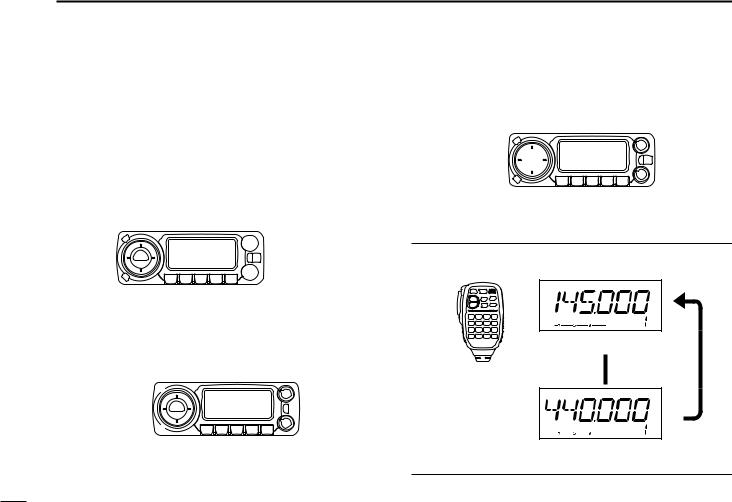
2. Selecting the operating frequency band
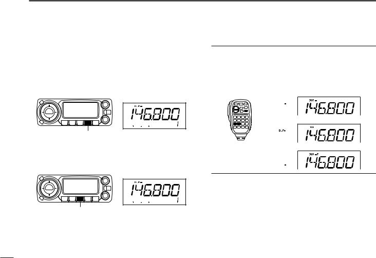
The IC-208H has 2 m and 70 cm transmittable bands.
[BAND] 

Push [BAND] to select the desired frequency band.
Push [BAND] to select the desired frequency band.
Using the HM-133
You can select the desired frequency band from the HM-133.
Push 
Push 
3. Tune the frequency
The tuning dial will allow you to dial in the frequency you want to operate. Pages 12 and 13 will instruct you on how to set the tuning speed.
[DIAL] 
Rotate [DIAL] to tune the frequency.
Using the HM-133
You can directly enter the frequency with the HM-133 keypad for the main band.
[EXAMPLE]: Setting frequency to 145.3625 MHz. Push 


Push 
Push 
Push 
QUICK REFERENCE GUIDE
Quick reference guide
VIII
QUICK REFERENCE GUIDE
■ Repeater operation
1. Setting duplex
Push [BAND] to select the frequency band.
Push [LOW•DUP] for 1 sec. once or twice to select minus duplex or plus duplex.
•The USA version has an auto repeater function, therefore, setting duplex is not required.
[LOW•DUP]
2. Repeater tone
Push [TONE•T-SCAN] several times until “T” appears, if the repeater requires a subaudible tone to be accessed.
[TONE•T-SCAN]
Using the HM-133
Plus or minus duplex selection and the repeater tone setting can be made easily via HM-133.
Push [DUP– 7(TONE)] for minus duplex; [DUP+ 8(TSQLS)] for plus duplex selection, push [FUNC] then [DUP– 7(TONE)] to turn the repeater tone ON.
Push 
Push 
Push  , then
IX
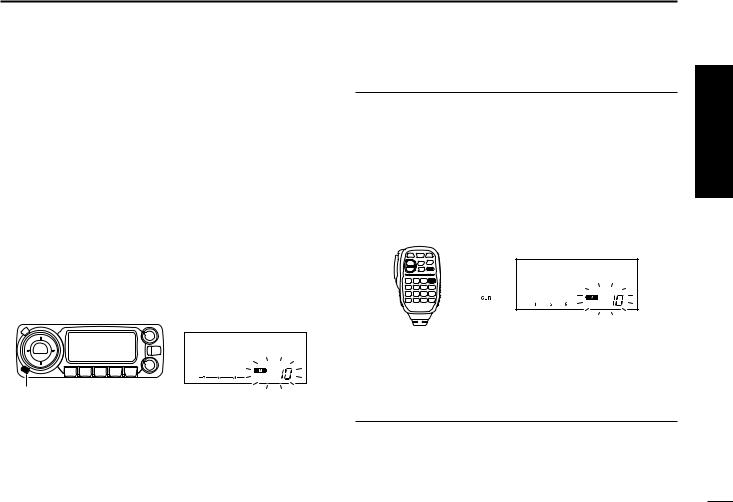
■ Programming memory channels
The IC-208H has a total of 512 memory channels (including 10 scan edges and 2 call channels) for storing often used operating frequency, repeater settings, etc.
1. Setting a frequency
In VFO mode, set the desired operating frequency with repeater, tone and tuning steps, etc.
Push [V/MHz•SCAN] to select VFO.
Rotate [DIAL] to set the desired frequency.
•Set other data, such as repeater tone, duplex information, tuning step), if desired.
QUICK REFERENCE GUIDE
Using the HM-133
qIn VFO mode, set the desired operating frequency, including offset direction, tone settings, etc.
Push [VFO/LOCK] to select VFO.
Push [ENT C(T-OFF)] first, then enter the desired operating frequency via the keypad.
•Set other data, such as repeater tone, duplex information, tuning step, if necessary.
wPush [FUNC] then [CLR A(MW)].
•“!” indicator and memory channel number blink.
2. Selecting a memory channel
Push [S.MW•MW], then rotate [DIAL] to select the desired memory channel.
• “!” indicator and memory channel number blink.
[S.MW•MW]
3. Writing a memory channel
Push and hold [S.MW•MW] for 1 sec. to program.
•3 beeps sound
•Return to VFO mode automatically after the program.
•Memory channel number automatically increases when continuing to push [S.MW•MW] after programming.
Push  , then
e Push [Y]/[Z] to select the desired memory channel.
rPush [FUNC] then push [CLR A(MW)] for 1 sec. to program.
•3 beeps sound
•Memory channel number automatically increases when continuing to push [CLR A(MW)] after programming.
Quick reference guide
X
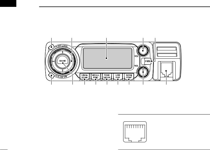
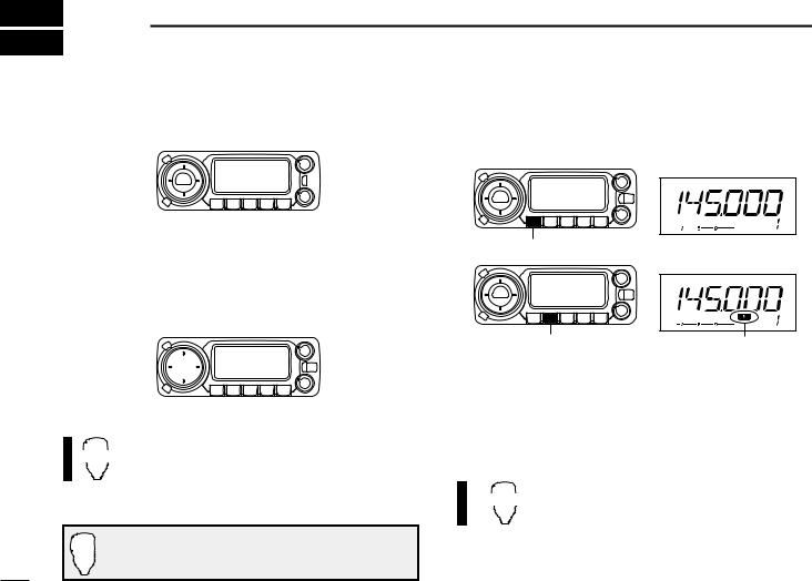
 1 PANEL DESCRIPTION
■ Front panel— controller
q |
w |
Function display (p. 3) |
e |
r |
!3 |
!2 |
!1 |
!0 |
o |
i |
u |
y |
t |
qSET•LOCK SWITCH [SET•LOCK]
Enters set mode when pushed. (p. 56)
Switches the lock function ON and OFF when pushed for 1 sec. (p. 14)
wTUNING DIAL [DIAL]
Selects the operating frequency (p. 12), memory channel (p. 26), the setting of the set mode item and the scanning direction (p. 41).
eVOLUME CONTROL [VOL] (p. 15)
Adjusts the audio level.
rPOWER SWITCH [PWR]
Turns power ON and OFF when pushed for 1 sec.
tMICROPHONE CONNECTOR
Connects the supplied or an optional microphone.
q +8 V DC output (Max. 10 mA) w Channel up/down
e 8 V control IN
qi r PTT
t GND (microphone ground) y MIC (microphone input) u GND
i Data IN
1
ySQUELCH CONTROL [SQL]
Varies the squelch level. (p. 15)
•The RF attenuator activates and increases the attenuation when rotated clockwise to the center position and further. (p. 16)
uMONITOR•DTMF SWITCH [MONI•DTMF]
Push to switch the monitor function ON and OFF. (p. 15)
Turns DTMF memory encoder ON and OFF when pushed for 1 sec. (p. 48)
iOUTPUT POWER•DUPLEX SWITCH [LOW•DUP]
Each push changes the output power selection. (p. 17)
Push for 1 sec. to select DUP–, DUP+ and simplex operation. (p. 20)
oTONE•TONE SCAN SWITCH [TONE•T-SCAN]
Each push selects a tone function. (pgs. 20, 52)
•Subaudible tone encoder, pocket beep (CTCSS), tone squelch, pocket beep (DTCS), DTCS squelch or tone function OFF can be selected.
Push for 1 sec. to start the tone scan. (p. 55)
!0MEMORY/CALL•PRIORITY SWITCH [M/CALL•PRIO]
Push to select and toggle memory, call and weather channel* modes. (pgs. 11, 26, 38, 66)
*Weather channels are available for USA version only.
Starts priority watch when pushed for 1 sec. (p. 47)
!1VFO/MHz TUNING•SCAN SWITCH [V/MHz•SCAN]
Selects and toggles VFO mode and 1 MHz (or 10 MHz for some versions) tuning when pushed. (p. 11)
Starts scan when pushed for 1 sec. (p. 41)
• Cancels a scan when pushed during scan.
PANEL DESCRIPTION |
1 |
|
!2BAND SWITCH [BAND] |
|
|
1 |
||
Push to select the operating frequency band. (p. 11) |
|
|
Push to select the call channel 1or 2 during call channel operation. (p. 38)
Push for 1 sec. to select the operating mode. (p. 65)
!3MEMORY WRITE SWITCH [S.MW•MW] (pgs. 27, 39, 42)
Selects a memory channel for programming when pushed.
Programs the selected memory channel when pushed for 1 sec.
!4
!4CONTROLLER RELEASE LATCH
While pushing this latch, slide the controller to the left to remove it.
2
1 PANEL DESCRIPTION
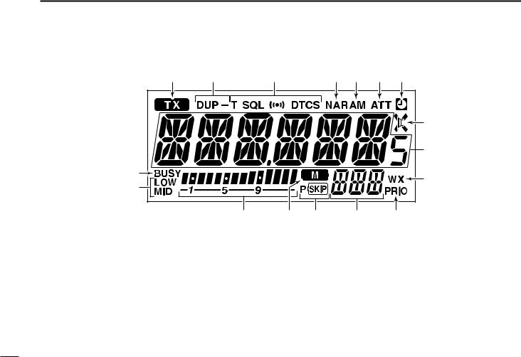
■ Function display
q |
w |
e |
r |
t |
y |
u |
|
|
|
|
|
|
i |
|
|
|
|
|
|
o |
!7 |
|
|
|
|
|
!0 |
|
|
|
|
|
|
|
!6 |
|
|
|
|
|
|
|
!5 |
!4 |
!3 |
!2 |
|
!1 |
qTRANSMIT INDICATOR
Appears while transmitting. (p. 17)
Blinks while transmitting with the one-touch PTT function. (p. 18)
wDUPLEX INDICATORS (p. 20)
“DUP” appears when plus duplex, “DUP –” appears when minus duplex (repeater) operation is selected.
eTONE INDICATORS
“T” appears while the subaudible tone encoder is in use. (p. 20)
“T SQL” appears while the tone squelch function is in use. (p. 52)
“DTCS” appears while the DTCS squelch function is in use. (p. 52)
“S” appears with the “T SQL” or “DTCS” indicator while the pocket beep function (with CTCSS or DTCS) is in use. (p. 52)
3

rNARROW MODE INDICATOR (p. 65)
Appears when the FM/AM narrow mode is selected. Narrow mode is available with USA version only.
tAM INDICATOR (p. 65)
Appears when AM mode is selected.
ySQUELCH ATTENUATOR INDICATOR (p. 16)
Appears when the squelch attenuator function is activated.
• The attenuator can be switched OFF in initial set mode. (p. 63)
uAUTO POWER-OFF INDICATOR (p. 62)
Appears while the auto power OFF function is in use.
iAUDIO MUTE INDICATOR (P. 18)
Appears when the audio mute function is activated.
•The mute can only be switched ON and OFF from the HM-133 only.
oFREQUENCY READOUT
Shows the operating frequency, channel names, set mode contents, etc.
•Frequency decimal point blinks while scanning. (p. 41)
•“d” appears in place of the 1st digit while the DTMF memory function is in use. (p. 48)
!0WEATHER ALERT INDICATOR (p. 66)
Appears when the weather alert function is activated.
• The either alert function is available with the USA version only.
!1PRIORITY INDICATOR (p. 47)
Appears while the priority watch is activated; blinks while the watch is paused.
PANEL DESCRIPTION |
1 |
!2MEMORY CHANNEL NUMBER INDICATORS |
1 |
Shows the selected memory channel number. (p. 26)Shows the selected bank initial. (p. 35)
“C” appears when the call channel is selected. (p. 38)“L” appears when the lock function is activated. (p. 14)
!3SKIP INDICATORS (p. 44)
“~”appears when the displayed memory channel is specified as a skip channel.
“P ~” appears when the displayed frequency is specified as a program skip frequency.
!4MEMORY INDICATOR (pgs. 11, 26) Appears when memory mode is selected.
!5S/RF INDICATORS
Shows the relative signal strength while receiving signals. (p. 15)
Shows the output power level while transmitting. (p. 17)
!6OUTPUT POWER INDICATORS
“LOW” appears when low output power; “MID” appears when middle output power is selected.
No indicator appears when high output power is selected.
!7BUSY INDICATOR
Appears when a signal is being received or the squelch is open. (p. 15)
Blinks while the monitor function is activated. (p. 15)
4
1 PANEL DESCRIPTION
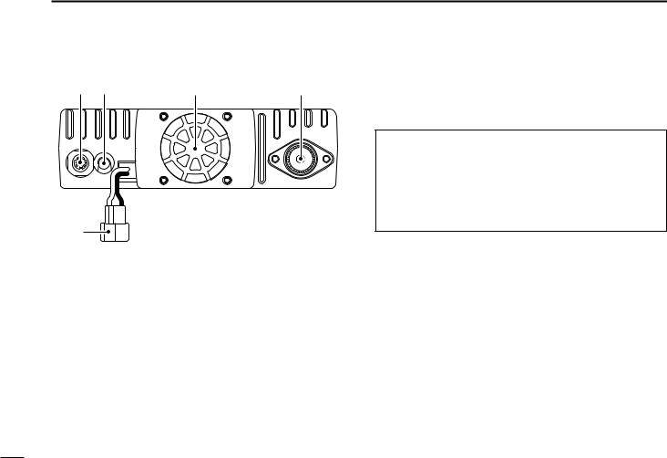
■ Rear Panel
q w |
e |
r |
t
qDATA SOCKET [DATA]
Connects a TNC (Terminal Node Controller), etc. for data communications.
• See p. 6 for connection information.
wEXTERNAL SPEAKER JACK [SP]
Connects an 8 Ω speaker.
• Audio output power is more than 2.0 W.
eCOOLING FAN
Rotates while transmitting.
Also rotates while receiving depending on the setting in initial set mode. (p. 63)
rANTENNA CONNECTOR [ANT]
Connects a 50 Ω antenna with a PL-259 connector and a 50 Ω coaxial cable.
ANTENNA INFORMATION
For radio communications, the antenna is of critical importance, to maximize your output power and receiver sensitivity. The transceiver accepts a 50 Ω antenna and less than 1:1.5 of Voltage Standing Wave Ratio (VSWR). High SWR values not only may damage the transceiver but also lead to TVI or BCI problems.
tPOWER RECEPTACLE [DC13.8V]
Accepts 13.8 V DC ±15% with the supplied DC power cable.
NOTE: DO NOT use a cigarette lighter socket as a power source when operating in a vehicle. The plug may cause voltage drops and ignition noise may be superimposed onto transmit or receive audio.
5
DDATA JACK PIN ASSIGNMENT
q
 w
w
e

 r
r
t |
y Front panel view |
qDATA IN
Input terminal for data transmit. See p. 63 for details on how to toggle data speed between 1200 (AFSK) and 9600 bps (G3RUH, GMSK).
wGND
Common ground for DATA IN, DATA OUT and AF OUT. ePTT P
PTT terminal for packet operation only. Connect ground to transmit data.
rDATA OUT
Data out terminal for 9600 bps operation only. tAF OUT
Data out terminal for 1200 bps operation only. yP SQL
Becomes high (+5 V) when the transceiver receives a signal which opens the squelch.
•To avoid unnecessary TNC transmission, connect squelch to the
TNC to inhibit transmission when receiving signals.
•Keep audio output at a normal level, otherwise a “P SQL” signal will not be output.
PANEL DESCRIPTION 1
1
6
1 PANEL DESCRIPTION
■ Microphone (HM-133*)
|
!1 |
q |
!0 |
w |
o |
e |
i |
|
u |
r |
y |
|
Mic element |
t |
|
*A different microphone may be supplied depending on version.
qVFO/LOCK SWITCH [VFO/LOCK]
Push to select VFO mode. (p. 11)
Push for 1 sec. to switch the lock function ON and OFF. (p. 14)
wPTT SWITCH
Push and hold to transmit; release to receive.
Switches between transmitting and receiving while the one-touch PTT function is in use. (p. 18)
eUP/DOWN SWITCHES [Y]/[Z]
Push either switch to change operating frequency, memory channel, set mode setting, etc. (pgs. 12, 26, 56)
Push either switch for 1 sec. to start scanning. (p. 41)
rACTIVITY INDICATOR
Lights red while any key, except [FUNC] and [DTMF-S], is pushed, or while transmitting.
Lights green while the one-touch PTT function is in use.
tKEYPAD (pgs. 8, 9)
yFUNCTION INDICATOR
Lights orange while [FUNC] is activated—indicates the secondary function of switches can be accessed.
Lights green when [DTMF-S] is activated—DTMF signals can be transmitted with the keypad.
u2nd FUNCTION SWITCH [FUNC]
iDTMF SELECT SWITCH [DTMF-S] (p. 50)
oFUNCTION SWITCHES [F-1]/[F-2] (p. 67)
Program and recall your desired transceiver conditions.
!0BAND SWITCH [BAND]
Push to select the frequency band. (p. 11)
Push for 1 sec. to select the operating mode. (p. 65)
!1MEMORY/CALL SWITCH [MR/CALL]
Push to select memory mode. (p. 11)
Push for 1 sec. to select call channel. (p. 38)
7

|
|
|
|
PANEL DESCRIPTION 1 |
|||||
■ Microphone keypad |
|
|
|
|
|
|
|
|
|
|
|
|
|
1 |
|||||
|
|
|
|
|
|
|
|
||
KEY |
FUNCTION |
|
SECONDARY FUNCTION ( |
+key) |
OTHER FUNCTIONS |
|
|
|
|
|
|
|
|
|
|
|
|
||
|
Switches between opening and closing the |
In memory mode enters bank selecting |
|
|
|
|
|
||
|
squelch. |
(p. 15) |
condition. |
(p. 35) |
|
|
|
|
|
|
|
|
|
|
|
|
|
|
|
|
Starts and stops scanning. |
(p. 41) |
Starts and stops tone scanning. |
(p. 55) |
|
|
|
|
|
|
|
|
|
|
|
|
|
|
|
|
Starts and stops priority watch. |
(p. 47) |
Turns the one-touch PTT function ON and |
|
|
|
|
|
|
|
|
|
OFF. |
(p. 18) |
|
|
|
|
|
|
|
|
|
|
|
|
|
|
|
|
Selects high output power. |
(p. 17) |
Turns the DTCS squelch ON. |
(p. 54) |
|
|
|
|
|
|
|
|
|
|
After pushing |
: |
|
|
|
|
Selects mid. output power. |
(p. 17) |
Turns the DTCS pocket beep function ON. |
|
|
|
|||
|
Transmits the |
appropriate |
|
|
|||||
|
|
|
|
(p. 53) |
DTMF code. |
(pgs. 23, 50) |
|
|
|
|
Selects low output power |
(p. 17) |
Turns the DTMF memory encoder function |
When the DTMF memory en- |
|
|
|
||
|
|
|
ON. |
(p. 50) |
coder is activated, push [0] to |
|
|
||
|
|
|
|
|
[9] to transmit the appropriate |
|
|
||
|
Selects minus duplex operation. |
(p. 21) |
Turns the subaudible tone encoder ON. |
|
|
|
|||
|
DTMF memory contents. |
|
|
|
|||||
|
|
|
|
(p. 21) |
|
|
|||
|
|
|
|
|
|
(p. 50) |
|
|
|
|
Selects plus duplex operation. |
(p. 21) |
Turns the CTCSS pocket beep function |
|
|
|
|
||
|
|
|
|
|
|
||||
|
|
|
ON. |
(p. 53) |
|
|
|
|
|
|
|
|
|
|
|
|
|
|
|
|
Selects simplex operation. |
(p. 21) |
Turns the tone squelch function ON. |
|
|
|
|
|
|
|
|
|
|
(p. 54) |
|
|
|
|
|
|
|
|
|
|
|
|
|
|
|
|
Increases audio output level. |
(p. 15) |
Sends a 1750 Hz tone signal while pushing |
|
|
|
|
|
|
|
|
|
and holding. |
(p. 23) |
|
|
|
|
|
|
|
|
|
|
|
|
|
|
|
|
|
|
|
|
|
|
|
|
|
8

1 PANEL DESCRIPTION
KEY |
FUNCTION |
|
SECONDARY FUNCTION ( |
+key) |
OTHER FUNCTIONS |
|
|
|
|
|
|
|
|
|
Cancels frequency entry. |
(p. 12) |
Selects a memory channel for program- |
|
|
|
|
Cancels the scan or priority watch. |
ming. |
(p. 28) |
|
|
|
|
|
(pgs. 41, 47) |
Advances the memory channel number |
|
|
|
|
Exit set mode. |
(p. 56) |
when continuously pushed after pro- |
|
|
|
|
|
|
gramming is completed. |
(p. 28) |
|
|
|
|
|
|
|
|
|
|
Enters set mode |
(p. 56) |
DTMF memory encoder function OFF. |
|
|
|
|
Advances the set mode selection order |
|
(p. 50) |
|
|
|
|
after entering set mode. |
(p. 56) |
|
|
|
|
|
|
|
|
|
||
|
Sets the keypad for numeral input. |
Turns the subaudible tone encoder, pocket |
After pushing |
: |
||
|
|
(p. 12) |
beep or CTCSS/DTCS tone squelch OFF. |
Transmits the |
appropriate |
|
|
Reverses the set mode selection order |
(pgs. 21, 53) |
||||
|
DTMF code. |
(pgs. 23, 50) |
||||
|
after entering set mode. |
(p. 56) |
|
|
|
|
|
|
|
|
|
|
|
|
Adjusts the squelch level increments. |
Mutes the audio. |
(p. 18) |
|
|
|
|
|
(p. 15) |
• Mute function is released when any oper- |
|
|
|
|
|
|
ation is performed. |
|
|
|
|
|
|
|
|
|
|
|
Decreases audio output level. |
(p. 15) |
Sends a 1750 Hz tone signal for 0.5 sec. |
|
|
|
|
|
|
|
(p. 23) |
|
|
|
|
|
|
|
||
|
Adjusts the squelch level decrement. |
Locks the digit keys on the keypad (includ- |
|
|
||
|
|
(p. 15) |
ing the A to D, # and Mkeys). |
(p. 14) |
|
|
|
|
|
|
|
|
|
9
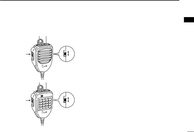
■Optional Microphones
(HM-118N/TN/TAN)
•HM-118N  w
w
ON
q |
e |
|
|
|
OFF |
• HM-118TN/TAN  w (DTMF)
ON
q |
e |
|
OFF
 r
r
PANEL DESCRIPTION 1
1
qPTT SWITCH
Push and hold to transmit; release to receive. wUP/DOWN SWITCHES [UP]/[DN]
Push either switch to change operating frequency, memory channel, set mode setting, etc. (pgs. 12, 26, 56)
Push either switch for 1 sec. to start scanning. (p. 41)
eUP/DN LOCK SWITCH
Slide to toggle [UP]/[DN] switches function ON and OFF.
rKEYPAD (HM-118TN/TAN only)
While pushing [PTT], push the desired key to send the DTMF code.
10
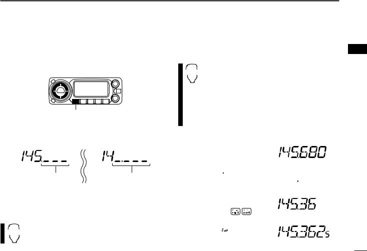
2 SETTING A FREQUENCY |
|
■ Preparation |
DVFO and memory modes |
DTurning power ON/OFF |
The transceiver has 2 basic operating modes: VFO mode and |
memory mode. Select VFO mode first to set an operating fre- |
|
|
quency. |
 [PWR]
[PWR]
Push [PWR] for 1 sec. to turn power ON and OFF.
[V/MHz•SCAN]
DOperating frequency band selection
The IC-208H has 2 m and 70 cm bands for transmission and reception. In addition, extra frequency bands 127, 220, 350, 500 and 900 MHz bands are available for wide-band receiver capability (except Taiwan and Korean version).
[BAND] 

Push [BAND] to select the desired frequency band.
Push [BAND] to select the desired band.
BAND
Note that in this manual, sections beginning with a microphone icon (as above), designate operation via the HM-133 microphone.
[M/CALL•PRIO] |
Appears |
Push [V/MHz•SCAN] to select VFO mode.
•When VFO mode is already selected, the digit below 10 MHz (the digit below 1 MHz or 100 kHz disappear depending on versions) disappear. In this case, push [V/MHz•SCAN] again (or twice or 3 times depending on version).
Push [M/CALL•PRIO] to select memory mode.
•“!” indicator appears when memory mode is selected.
Push [VFO/LOCK] to select VFO mode. VFO/LOCK Push [MR/CALL] to select memory mode.
11
■ Using the tuning dial
qRotate [DIAL] to set the frequency.
•If VFO mode is not selected, push [V/MHz•SCAN] to select VFO mode.
•The frequency changes in the selected tuning steps. (p. 13)
[DIAL] 
[V/MHz•SCAN]
wTo change the frequency in 1 MHz (10 MHz for some versions) steps, push [V/MHz•SCAN], then rotate [DIAL].
•Pushing [V/MHz•SCAN] for 1 sec. starts scan function. If scan starts, push [V/MHz•SCAN] again to cancel it.
While 1 MHz tuning step is |
While 10 MHz tuning step |
selected, the digit below |
is selected, the digit below |
100 kHz disappear. |
1 MHz disappear. |
■Using the [Y]/[Z] keys
Push [Y] or [Z] to select the desired frequency.
YZ • Pushing [Y]/[Z] for 1 sec. activates a scan. If scan starts, push [Y]/[Z] or [CLR A(MW)] to cancel it.
SETTING A FREQUENCY 2
■ Using the keypad
The frequency can be directly set via numeral keys on the mi- 2 crophone.
ENT |
z Push [VFO/LOCK] to select VFO mode, if neces- |
sary. |
|
C |
x Push [ENT C(T-OFF)] to activate the keypad for |
|
digit input. |
cPush 6 keys to input a frequency.
•When a digit is mistakenly input, push [ENT C(T-OFF)] to clear the input, then repeat input from the 1st digit.
•Pushing [CLR A(MW)] clears input digits and retrieves the frequency.
[EXAMPLE]: Setting frequency to 145.3625 MHz.
Push 
Push 
Push 


Push 
12
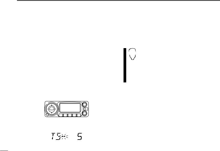
2 SETTING A FREQUENCY
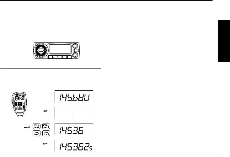
■ Tuning step selection
[
Tuning steps are the minimum frequency change increments when you rotate [DIAL] or push [Y]/[Z] on the microphone. Independent tuning step for each frequency bands can be set for individual tuning convenience. The following tuning steps are available.
• 5 kHz |
• 10 kHz |
• 12.5 kHz |
• 15 kHz |
• 20 kHz |
• 25 kHz |
• 30 kHz |
• 50 kHz |
• 100 kHz |
• 200 kHz |
|
|
NOTE: For convenience, select a tuning step that matches the frequency intervals of repeaters in your area.
qPush [BAND] to select the desired frequency band.
•Push [V/MHz•SCAN] to select VFO mode, if necessary.
wPush [SET•LOCK] to enter set mode.
[SET•LOCK] 
ePush [SET•LOCK] or [S.MW•MW] several times until “TS” appears as shown below.
rRotate [DIAL] to select the desired tuning step. tPush [V/MHz•SCAN] to exit set mode.
z Push [BAND] to select the desired frequency SET band.
B• Push [VFO/LOCK] to VFO mode, if necessary. x Push [SET B(D-OFF)] to enter set mode.
cPush [SET B(D-OFF)] or [ENT C(T-OFF)] several times until “TS” appears.
v Push [Y] or [Z] to select the desired tuning step. b Push [CLR A(MW)] to exit set mode.
13
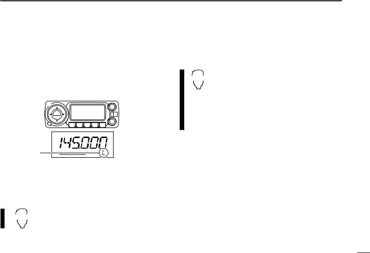
■ Lock functions
To prevent accidental frequency changes and unnecessary function access, use the lock function. The transceiver has 2 different lock functions.
DFrequency lock
This function locks [DIAL] and switches electronically and can be used together with the microphone lock function.
[SET•LOCK] 
“L” appears
Push [SET•LOCK] for 1 sec. to turn the lock function ON and OFF.
•[PTT], [MONI•DTMF] (monitor function only), [VOL] and [SQL] can be used while the channel lock function is in use. Also, TONE-1, TONE-2, DTMF tones or DTMF memory contents can be transmitted from the microphone.
Push [VFO/LOCK] for 1 sec. to switch the
VFO/LOCK |
lock function ON and OFF. |
SETTING A FREQUENCY 2
DMicrophone keypad lock |
2 |
This function locks the microphone keypad.
Push [FUNC] then [SQLZ D(16KEY-L)] to 16KEY-L switch the microphone keypad lock function
ON and OFF.
•[PTT], [VFO/LOCK], [MR/CALL], [BAND], [Y], [Z],
[F-1], [F-2] and [FUNC] on the microphone can be used.
•All switches on the transceiver can be used.
•The keypad lock function is released when the power is turned OFF then ON again.
14
 Loading...