


 Loading...
PROGRAMMING MANUAL
CLONING SOFTWARE
CS-F3G

FOREWORD
This manual explains in detail how to program each of the functions in the IC-F3GT/GS and IC-F4GT/GS VHF
AND UHF TRANSCEIVERS with the CS-F3G CLONING SOFT-
WARE. The CS-F3G can be set up to meet any number of requirements of your customers, such as system conditions, channels, frequencies, tones, etc.
IMPORTANT
Before using the program, make a backup copy of the original disk. Operate the program using the backup and keep the original in a safe place.
TABLE OF CONTENTS
FOREWORD . . . . . . . . . . . . . . . . . . . . . . . . . . . . . . i
IMPORTANT . . . . . . . . . . . . . . . . . . . . . . . . . . . |
. . . i |
TABLE OF CONTENTS . . . . . . . . . . . . . . . . . . . |
. . i |
1 PREPARATION . . . . . . . . . . . . . . . . . . . . . |
. 1 |
2 SCREEN DESCRIPTION . . . . . . . . . . . . . |
2–5 |
2-1 MAIN SCREEN DESCRIPTION . . . . . . . . . 2–3 2-2 TREE VIEW SCREEN DESCRIPTION . . . . 4–5
3 COMMON SETTING . . . . . . . . . . . . . . |
. 6–18 |
3-1 KEY & DISPLAY ASSIGN . . . . . . . . . . . |
. 6–12 |
3-2 COMMON 1 . . . . . . . . . . . . . . . . . . . . . . |
13–14 |
3-3 COMMON 2 . . . . . . . . . . . . . . . . . . . . . . |
15–16 |
3-4 EXPERT . . . . . . . . . . . . . . . . . . . . . . . . |
17–18 |
4 MEMORY CHANNEL— LMR . . . . . . . . 19–23 5 MEMORY CHANNEL— PMR . . . . . . . . 24–32
6 DTMF AUTODIAL . . . . . . . . . . . . . . . . 33–34
6-1 DTMF AUTODIAL . . . . . . . . . . . . . . . . . . . . 33 6-2 DTMF SETTING . . . . . . . . . . . . . . . . . . . . . 34
7 CONTINUOUS TONE . . . . . . . . . . . . . |
. . . 35 |
8 SCAN LIST . . . . . . . . . . . . . . . . . . . . . |
36–37 |
8-1 SCAN LIST . . . . . . . . . . . . . . . . . . . . . . . . . 36 8-2 SCAN SETTING . . . . . . . . . . . . . . . . . . . . . 37
9 2TONE . . . . . . . . . . . . . . . . . . . . . . . . . 38–40
9-1 RX CODE CHANNEL . . . . . . . . . . . . . . . 38–39 9-2 TX CODE . . . . . . . . . . . . . . . . . . . . . . . . . . 40 9-3 2TONE SETTING . . . . . . . . . . . . . . . . . . . . 40
10 5TONE . . . . . . . . . . . . . . . . . . . . . . . . 41–49
10-1 RX CODE CHANNEL . . . . . . . . . . . . . . 41–42 10-2 TX CODE CHANNEL . . . . . . . . . . . . . . 43–44 10-3 FORMAT . . . . . . . . . . . . . . . . . . . . . . . . . . 45 10-4 USER TONE . . . . . . . . . . . . . . . . . . . . . . . 46 10-5 5TONE SETTING . . . . . . . . . . . . . . . . 47–49
11 PROGRAMMING for SmarTrunk II operation
. . . . . . . . . . . . . . . . . . . . . . . . . . . . . . . 50–52
11-1 STARTING THE PROGRAM . . . . . . . . . . . 50 11-2 PROGRAMMING RECOMMENDATION . . . 50 11-3 Speed Dial . . . . . . . . . . . . . . . . . . . . . . . . . 51 11-4 Configuration . . . . . . . . . . . . . . . . . . . . . . . 52
12 PROGRAMMING for LTR® TRUNKING operation . . . . . . . . . . . . . . . . . . . . . . 53–54
12-1 STARTING THE PROGRAM . . . . . . . . . . . 53 12-2 Global . . . . . . . . . . . . . . . . . . . . . . . . . . . . 53 12-3 System 1, System 2 . . . . . . . . . . . . . . . . . . 54
13 DATA CLONING BETWEEN TRANSCEIVERS . . . . . . . . . . . . . . . . . . . 55
14 PROGRAMMING EXAMPLE . . . . . . . 56–83
14-1 EXAMPLE 1 . . . . . . . . . . . . . . . . . . . . . 56–59 14-2 EXAMPLE 2 . . . . . . . . . . . . . . . . . . . . . 60–61 14-3 EXAMPLE 3 . . . . . . . . . . . . . . . . . . . . . 62–65 14-4 EXAMPLE 4 . . . . . . . . . . . . . . . . . . . . . 66–69 14-5 EXAMPLE 5 . . . . . . . . . . . . . . . . . . . . . 70–73 14-6 EXAMPLE 6 . . . . . . . . . . . . . . . . . . . . . 74–78 14-7 EXAMPLE 7 . . . . . . . . . . . . . . . . . . . . . 79–83
15 OPTIONAL UNIT INSTALLATION . . . 84–85
■ GENERAL . . . . . . . . . . . . . . . . . . . . . . . . . . . 84 15-1 INSTALLATION . . . . . . . . . . . . . . . . . . . . . 84 15-2 HARDWARE SETUP . . . . . . . . . . . . . . . . . 85
16 PAGER/CODE SQUELCH . . . . . . . . . 86–93
16-1 PAGER FUNCTION . . . . . . . . . . . . . . . 86–89 16-2 CODE SQUELCH FUNCTION . . . . . . . 90–93
17 SPECIAL FUNCTION . . . . . . . . . . . . . . . 94
17-1 CPU REVISION INDICATION . . . . . . . . . . 94 17-2 USER SET MODE . . . . . . . . . . . . . . . . . . . 94
18 INDEX . . . . . . . . . . . . . . . . . . . . . . . . 95–97
i
PREPARATION 1
■ EQUIPMENT REQUIRED
To use the program, the following hardware and software is required:
•IBM PC/AT or PS/2 compatible computer with an RS-232C serial port
•Microsoft® Windows® 95 or Windows® 98
•Intel Pentium 100 MHz processor or faster
•At least 16 MB RAM
•At least 800×600 pixel display
•OPC-478 CLONING CABLE
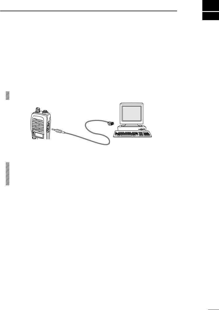
■CONNECTION
Connect each item as in the following diagram.
CAUTION: Do not connect an antenna to the transceiver during cloning operation. Received signals may cause cloning errors.
DB9 female plug |
Personal |
|
(incl. level converter circuit) |
||
computer |
||
to an RS-232C port |
||
|
to the speaker connector
OPC-478
■ SOFTWARE INSTALLATION
NOTE:
1.Before using the program, make a backup copy of the original disk. After making a backup copy, keep the original disk in a safe place.
2.Depending on your Windows® system files, the PC may require rebooting. In this case, repeat the installation from the beginning.
Installation
q Boot up Windows®. (Quit all applications when Windows® is running.) w Insert the CS-F3G backup disk into the appropriate floppy disk drive. e Select ‘Run’ from the [Start] menu.
r Type the setup program name with full path name, then press the [Enter] key. e.g.; A:\setup [Enter]
t Follow the prompts.
y Program group ‘CS-F3G’ appears in the ‘Programs’ folder of the start menu.
IBM PC/AT and PS/2 are trademarks of International Business Machines. Microsoft and Windows are registered trademarks of Microsoft Corporation.
1
2 SCREEN DESCRIPTION
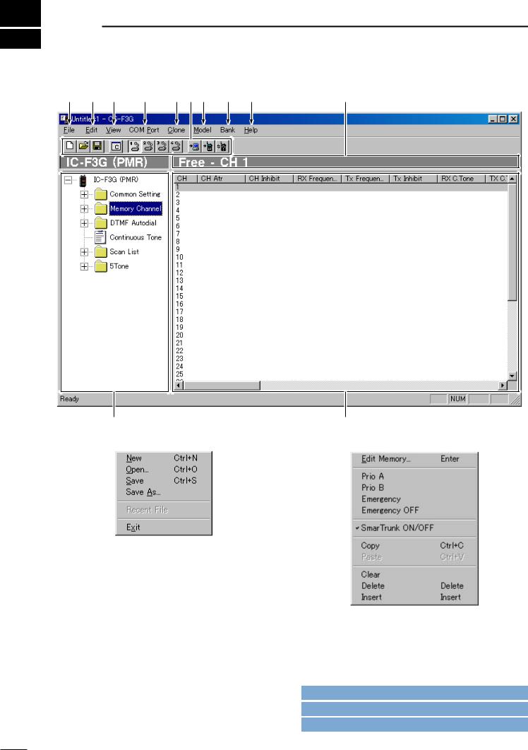
2-1 MAIN SCREEN DESCRIPTION |
|
|||||
q |
w e |
r |
t y u |
i |
o |
!0 |
!1
q FILE MENU— [File]
!2
w EDIT MENU— [Edit]
Used for making new file, opening available saved file, saving memory channel contents or quitting the program, etc.. Up to 4 recently used files are indicated in the sub menu for simple, quick file selection.
Edit the selected memory contents.
• Select the proper model type, item and channel number before editing items. (see u, !1and !2; p. 3)
*The above sub menu shows in the case that a memory channel is selected. When an other item is selected, a different sub menu is appears.
Go to u MODEL MENU— [Model]
Go to !1TREE VIEW SCREEN
Go to !2MEMORY CHANNEL SCREEN
2
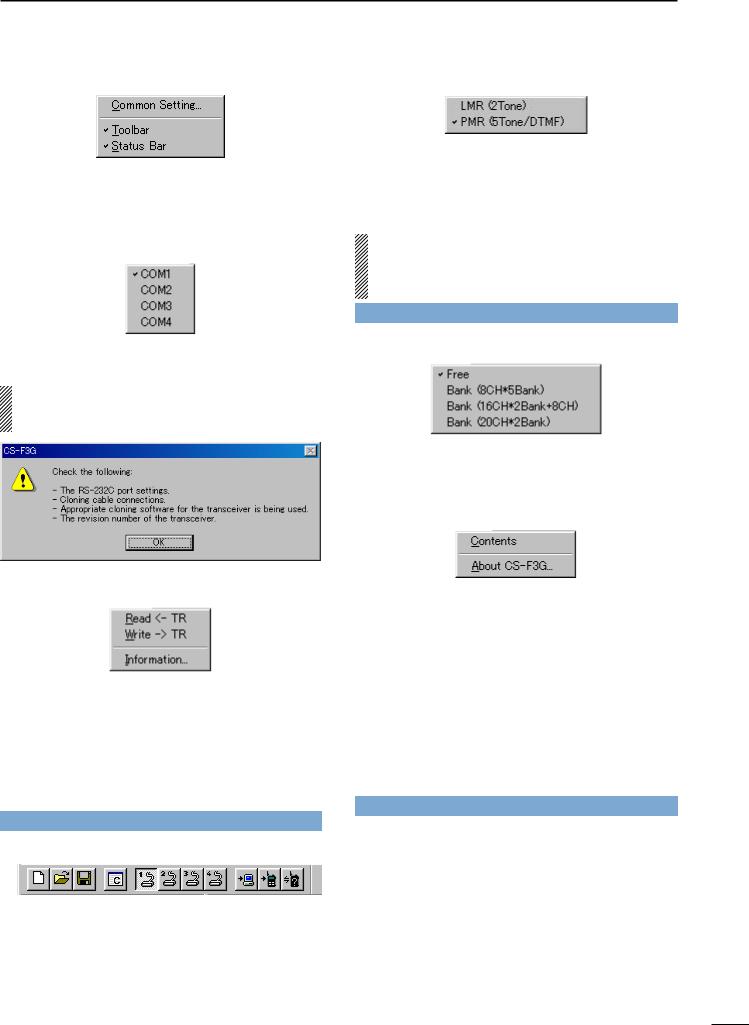
e VIEW MENU— [View]
•The independent Common Setting Screen is selectable. (pgs. 6–18)
•Turn the tool bar or status bar ON/OFF.
r COM PORT MENU— [COM Port]
Push to display the COM port setting sub menu.
• Set the COM port (RS-232C port) number properly.
NOTE: ‘Check the following’ dialog box as follows, appears when the RS-232C serial port is not set correctly.
t CLONE MENU— [Clone]
Starts to read the programmed data from the connected transceiver, programs setup data to the connected transceiver, or displays detailed information screen to check Model type, CPU’s revision, clone comment and optional unit installation condition of the connected transceiver.
The clone comment is programmed in Clone Comment— (1), (2) in 3-2 COMMON 1 (p. 14)
Go to Clone Comment— (1), (2)
y TOOL BAR
Short cut keys appear on the tool bar when the tool bar is checked (“ ” mark appears) in the [View] menu as above.
Short cut keys for New (Ctrl+N), Open (Ctrl+O), Save (Ctrl+S) as in [File], Common Setting as in [View], COM1–4 selection as in [COM Port] and Read <– TR, Write –> TR, Information as in [Clone] menu, are available.
SCREEN DESCRIPTIONS 2
u MODEL MENU— [Model]
Select model type from LMR (2-tone) or PMR (5- tone/DTMF).
-“ ” mark appears for the selected model.
The Tree View Screen will be changed when switched between LMR and PMR. See page 5 for details.
IMPORTANT! : The model type must be selected at first, otherwise the edited contents will be lost. Select PMR (5Tone/DTMF) to enable the DTMF decode operation when UT-108 is installed.
Go to 2-2 TREE VIEW SCREEN DESCRIPTION
i BANK MENU— [Bank]
Push to select bank type. Free, 8CH*5Bank, 16CH*2Bank + 8CH, 20CH*2Bank are available.
-“ ” mark appears for the selected bank type.
o HELP MENU— [Help]
Push to display help contents and cloning software revision information.
!0EDITABLE CHANNEL INDICATION
Displays the prompt editable item name and channel number.
!1TREE VIEW SCREEN (p. 4)
Double click the folder icon or click the “|+ ” beside the folder which you want to edit. Then double click the desired item name to display the item on the ‘Memory channel screen’.
Go to 2-2 TREE VIEW SCREEN DESCRIPTION
!2MEMORY CHANNEL SCREEN
Display the Memory Channel or editable item informa-
number, or press [Enter] key after desired channel selection to open the independent ‘Edit’ screen.
3
2 SCREEN DESCRIPTIONS
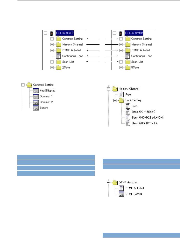
2-2 TREE VIEW SCREEN DESCRIPTION
• LMR Tree View |
• PMR Tree View |
q
w
e
r
t
 y u
y u
q Common setting (pgs. 6–18) |
w Memory Channel |
|
(LMR: pgs. 19–23/PMR: pgs. 24–32) |
Set programmable key, function display assign, and several commonly used timers, etc., are programmable in 4 independent sheets as follow.
Key & Display Assign (pgs. 6–12)
Common 1 (pgs. 13–14)
Common 2 (pgs. 15–16) Expert (pgs. 17–18)
By double clicking an item in the Common Setting folder, the desired sheet in the independent Common Setting Screen appears.
Go to 3-1 KEY & DISPLAY ASSIGN
Go to 3-2 COMMON 1
Go to 3-3 COMMON 2
Go to 3-4 EXPERT
Set channel attribute, operating frequency, CTCSS encoder/decoder frequency, transmit output power, voice scrambling code, etc..
By double clicking a bank type item in the Bank Setting folder, the desired bank condition is indicated below the Memory Channel folder and editable channel number, in a bank in the Memory Channel Screen.
Go to 4 MEMORY CHANNEL— LMR Go to 5 MEMORY CHANNEL— PMR
e DTMF Autodial (pgs. 33–34)
Program DTMF code for the DTMF auto dialling function and timers for each digit, 1st digit, [ ] and [#] code.
By double clicking the DTMF Autodial item, the editable DTMF channels appear in the Memory Channel Screen, and the independent DTMF Setting Screen appears when the DTMF Setting item is double clicked.
Go to 6 DTMF AUTODIAL
4

r Continuous Tone (p. 35)
Set continuous tone frequency. The programmed continuous tone is used for encoder and/or decoder.
By double clicking the Continuous Tone item, the editable continuous tone channels appear in the Memory Channel Screen.
Go to 7 CONTINUOUS TONE
t Scan List (pgs. 36–37)
Set scan mode, text for each scan group, power save function scan stop/resume timers, etc..
By double clicking the Scan List item, the editable scan group channels appear in the Memory Channel Screen, and the independent Scan Setting Screen appears when the Scan Setting item is double clicked.
Go to 8 SCAN LIST
y 2Tone (LMR only; pgs. 38–40)
Set RX/TX code, text, beep, bell, stun, group call, ANS functions, etc..
By double clicking the RX Code Channel item, the editable RX code channels appear in the Memory Channel Screen, and the independent TX Code Channel or 2Tone Setting Screen appears when the TX Code Channel or 2Tone Setting item is double clicked, respectively.
Go to 9 2TONE
SCREEN DESCRIPTIONS 2
u 5Tone (PMR only; pgs. 41–49)
Set RX/TX code, text, 5-tone format, beep, bell, stun, group call, answer back functions, etc..
By double clicking the RX/TX Code Channel, Format or User Tone item, the editable RX/TX code channels, 5-tone format or user tone appear in the Memory Channel Screen, and the independent 5Tone Setting Screen appears when the 5Tone Setting item is double clicked.
Go to 10 5TONE
5

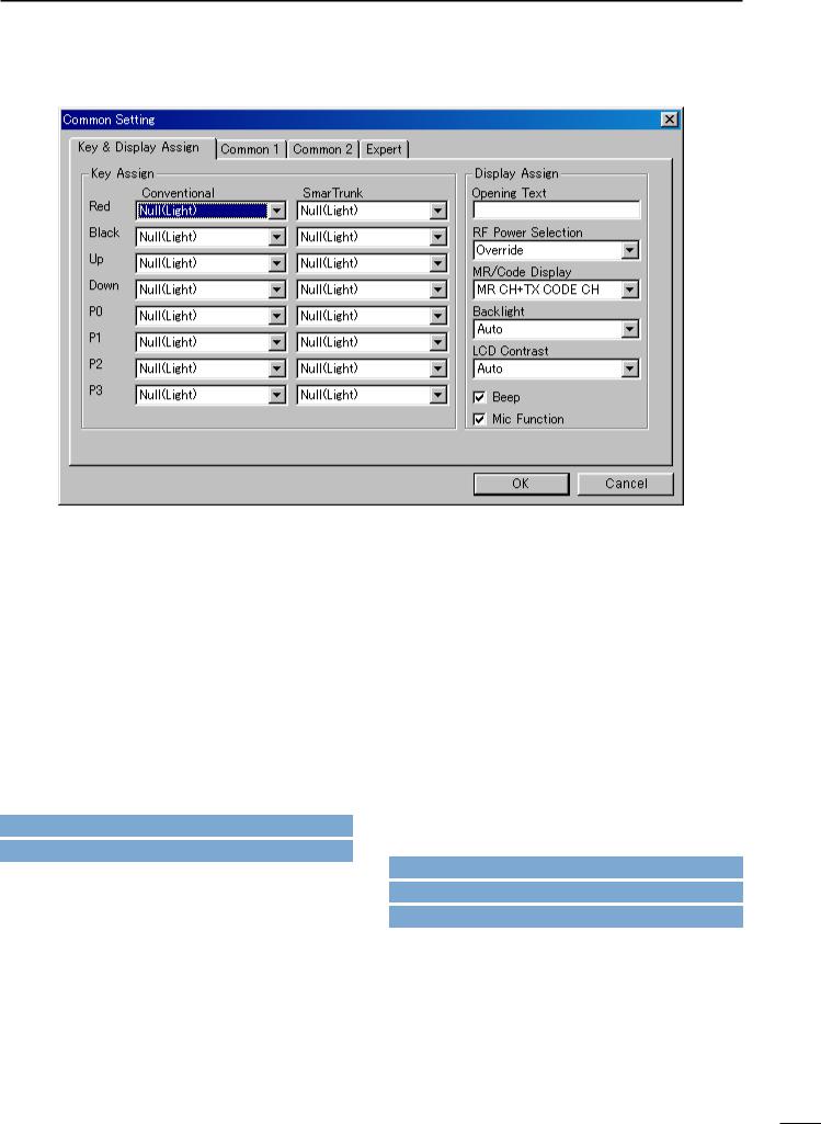
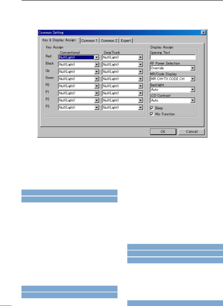
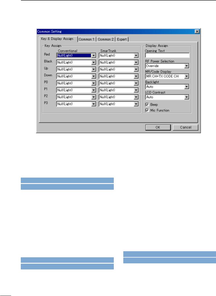
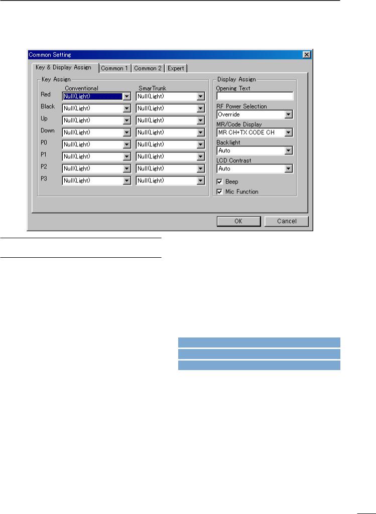
3 COMMON SETTING
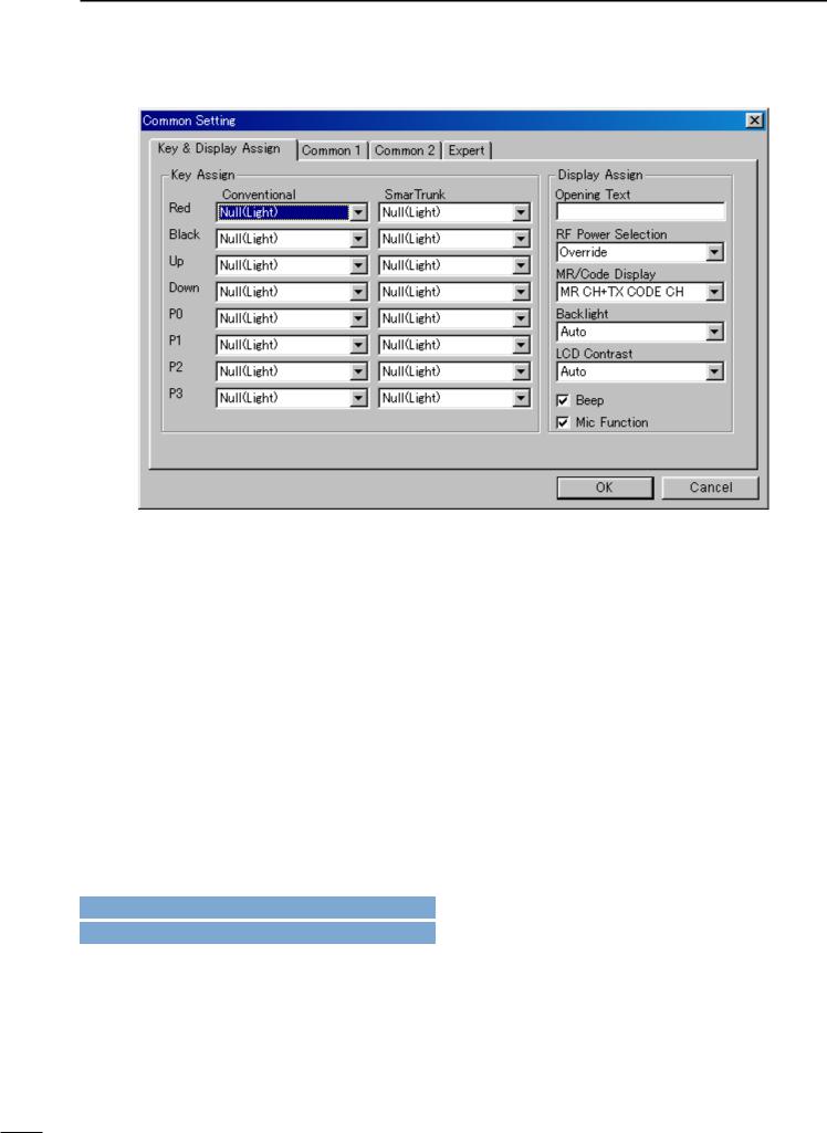
3-1 KEY & DISPLAY ASSIGN
■ Key Assign— Red, Black, Up (▲), Down (▼) , P0,
P1, P2, P3
Assign a function for each programmable switch and operating mode (Conventional and SmarTrunk). Assignable functions and actions are as follows.
Null(Light): No function is assigned. However, lights LCD backlight for 5 sec. when ‘Auto’ is selected in Backlight (p. 12) in this screen.
Go to Backlight
CH Up, CH Down:
Changes memory channel. Memory channel is selectable when assigning this function, besides the original [CH Up (▲)] or [CH Down (▼)] switches.
Bank Up : Changes memory channel bank for when either 8CH*5Bank, 16CH*2Bank + 8CH, 20CH*2Bank is selected in the BANK menu (p. 3) or, double click the desired bank icon in the Bank Setting folder in the Tree View Screen (p. 4).
Go to u BANK MENU
Go to w Memory Channel
Scan A, Scan B:
When the power ON scan function is turned OFF;
Push to start and cancel scanning operation. In case of transmission during scan, cancels scanning when in Scan A, and pauses scanning, then resumes scanning after passing the time period specified in
Auto Reset in 4/5 MEMORY CHANNEL
(LMR; p. 22/PMR; p. 31) when Scan B is selected.
The scanning list (scanning channel group) can be selected via [CH Up] or [CH Down] switches, after entering the scan list selection mode by pushing this switch for 1 sec..
When the power ON scan function is turned ON;
Push to pause scanning when in Scan A, and push to cancel scanning when Scan B is selected. In case of transmission during scan, pauses scanning, then resumes scanning after passing the time period specified in the Auto Reset in 4/5 MEMORY CHANNEL (LMR; p. 22/PMR; p. 31) when in Scan A. Cancels scanning when Scan B is selected.
The scanning list (scanning channel group) can be selected via [CH Up] or [CH Down] switches, after entering the scan list selection mode by pushing this switch for 1 sec..
The power ON scan function is specified in Power ON Scan in 8-2 SCAN SETTING (p. 37).
NOTE: Scan A and Scan B cannot be assigned at the same time because the transceiver cannot have two different scans.
Go to Auto Reset— LMR
Go to Auto Reset— PMR
Go to PWR ON Scan
6
COMMON SETTING 3
3-1 KEY & DISPLAY ASSIGN— continued
Scan Add/Del(Tag):
Push to add or delete the channel to/from the selected scanning list
Prio A, Prio B:
Selects the priority channel A or B programmed in CH Atr in 4/5 MEMORY CHANNEL respectively (LMR; p. 19/PMR: p. 24) by pushing this switch.
Prio A (Rewrite):
Selects the priority channel A programmed in CH Atr in 4/5 MEMORY CHANNEL
(LMR; p. 19/PMR: p. 24) by pushing this switch. Also the operating channel is reassigned for priority channel A by pushing this switch for 1 sec..
Go to CH Atr— LMR
Go to CH Atr— PMR
MR-CH 1–4:
Immediately selects memory channel 1–4, respectively.
Moni/Moni(Audi):
For LMR model action— Moni
Push to mute and release the CTCSS (DTCS) or 2-tone squelch mute. Open any squelches/deactivate any mutes while pushing this switch.
For PMR model action— Moni (Audi)
|
Activates a monitor function specified in |
|
|
Switch Action— |
Moni in 5 MEMORY |
|
CHANNEL— PMR |
(p. 27). |
|
|
|
|
Go to Switch Action— Moni |
|
Lock |
: Switches keyboard lock function ON and |
|
|
OFF. |
|
Beep |
: Switches key touch beep ON and OFF. |
|
High/Low: Switches transmit output power level from the independent settings of each channel. It is impossible to select “High” when “Low” is selected for the initial setting in RF PWR in 4/5 MEMORY CHANNEL (LMR; p. 22/PMR; p. 29) as well as when “MR CH Individual” is selected in the RF Power Selection (p. 11) in this sheet.
Go to RF PWR— LMR
Go to RF PWR— PMR
Go to RF Power Selection
7
3 COMMON SETTING
3-1 KEY & DISPLAY ASSIGN— continued
C. Tone CH Ent:
Selects continuous tone channel via [CH Up] or [CH Down] switches to change the tone frequency/code setting after pushing this switch for temporary operation.
The [CH Up] or [CH Down] switches are assigned in this screen (p. 6) and the continuous tone channel is programmed in 7 CONTINUOUS TONE (p. 35),
Go to CH Up, CH Down
Go to 7 CONTINUOUS TONE
Talk Around:
Toggles the talk around function ON and OFF.
This function allows temporary simplex operation on the duplex/repeater channel.
DTMF Autodial:
Push this switch for entering the DTMF autodial mode and then select the stored DTMF code via [CH Up] or [CH Down] switches.
Transmits the selected DTMF code by pushing this switch for 1 sec..
The DTMF code for auto dialling is programmed in 6-1 DTMF AUTODIAL (p. 33), and the [CH Up] or [CH Down] switches are assigned in this screen (p. 6).
Go to 6-1 DTMF Autodial
Go to CH Up, CH Down
Re-Dial |
: Transmits the last-transmitted DTMF code |
|
again. Acts for both manual and autodial. |
|
Re-Dial will be cleared when the transceiv- |
|
er is turned OFF once. |
Call |
: Transmits the 2-tone (LMR) or 5-tone or |
|
DTMF code (PMR) in the selected channel. |
|
2-tone is programmed in Option— 2Tone in |
|
4 MEMORY CHANNEL— LMR (p. 20) |
|
5-tone is programmed in 5Tone Signaling— |
|
RPT, STN, ID in 5 MEMORY CHANNEL— |
|
PMR (p. 29) |
For PMR model action only
In case this switch is pushed, and the 5- tone setting is an “OFF” channel, it transmits the previously transmitted 5-tone code, when the automatic clear channel searching function is activated, specified in the
Auto CH Call in 8-2 SCAN SETTING
(p. 37).
Go to Option— 2Tone
Go to 5Tone Signaling— RPT, STN, ID
Go to Auto CH Call
Call A (Code 30), Call B (Code 29)— PMR only : Transmits the 5-tone code programmed in the channel 30 (Call A) or 29 (Call B) in 10-2 TX CODE (p. 43) as the station code when [Call A] or [Call B] switch is pushed, respectively.
Go to 10-2 TX Code
8

3-1 KEY & DISPLAY ASSIGN— continued
Emergency Repeat, Emergency Single:
Immediately selects emergency channel and automatically sends a repeated emergency signal at specified time intervals or an emergency signal once, by pushing this switch for the specified time period, programmed in Emergency— SW ON Timer in 3-4 EXPERT (p. 17). Also, cancels the emergency call by pushing this switch for the specified time period, programmed in
Emergency— SW OFF Timer in 3-4 EXPERT (p. 17), before an emergency signal is transmitted.
The emergency channel is specified in CH Atr in 4/5 MEMORY CHANNEL (LMR; p. 19/PMR; p. 24) and the time intervals are specified in the Emergency— Start/Repeat in 3-4 EXPERT (p. 18).
Go to Emergency— SW ON Timer
Go to Emergency— SW OFF Timer
Go to CH Atr— LMR
Go to CH Atr— PMR
Go to Emergency— Start/Repeat
TX Code— PMR only :
Selects a TX code channel, instead of the specified 5-tone code channel programmed in 5Tone signaling— STN in 5 MEMORY CHANNEL— PMR (p. 29), via [CH Up] or [CH Down] switches after pushing this switch for temporary operation.
COMMON SETTING 3
The station code can also be manually entered as at above right.
To enter 5-tone code—
IC-F3GT/F4GT : Enter the station code using [0]–[9] and [ ] switches after pushing this switch for 1 sec..
IC-F3GS/F4GS: Select |
the |
code number via |
[CH Up] |
or |
[CH Down] switches |
after pushing this switch for 1 sec., then push this switch to set the next code number. After all digits are selected, push this switch for 1 sec. to complete the number.
Selectable 5-tone channels, acceptable input digits and updates can be specified in
Sel (p. 44), Input Digit (p. 43) and Update
(p. 43) in 10-2 TX CODE CHANNEL.
The [CH Up] and [CH Down] switches are assigned in this screen (p. 6).
Go to 5Tone signaling— STN
Go to Sel
Go to Input Digit
Go to Update
Go to CH Up, CH Down
9
3 COMMON SETTING
3-1 KEY & DISPLAY ASSIGN— continued
TX Code CH Up, TX Code CH Down— PMR only : Selects a TX code channel, instead of the specified 5-tone code channel programmed in 5Tone signaling— STN in 5 MEMORY CHANNEL— PMR (p. 29) for temporary operation.
Selectable 5-tone channels are specified in
Sel in 10-2 TX CODE CHANNEL (p. 44).
Go to 5Tone signaling— STN
Go to Sel
ID-MR Select:
For entering into received ID code history indication mode. Up to 5 codes can be memorized and searches the history with [CH Up] or [CH Down] switches.
All the history can be cleared by pushing this switch for 1sec..
For PMR action only—
The selected/displayed 5-tone code can be transmitted as STN (station/group) code when [Call] switch is pushed.
[CH Up], [CH Down] or [Call] switches are assigned in this screen (pgs. 6, 8).
Go to CH Up, CH Down
Go to Call
OPT1 Out/H, OPT2 Out/H, OPT3 Out/H:
Outputs “High” level signal from the OPT1–3 port in the optional unit connector (MAIN unit, J5; pins 9–11), respectively.
OPT1 Out/L, OPT2 Out/L, OPT3 Out/L:
Outputs “Low” level signal from the OPT1–3 port in the optional unit connector (MAIN unit, J5; pins 9–11), respectively.
OPT1 Momentary/H, OPT2 Momentary/H, OPT3 Momentary/H: Outputs “High” level pulse signal from the OPT1–3 port in the optional unit connector (MAIN unit, J5; pins 9–11), respectively.
OPT1 Momentary/H, OPT2 Momentary/H, OPT3 Momentary/H: Outputs “Low” level pulse signal from the OPT1–3 port in the optional unit connector (MAIN unit, J5; pins 9–11), respectively.
Sp. Func 1, Sp. Func 2:
Reserved for future functions.
Scrambler: Switches voice scrambler function ON and OFF when an optional voice scrambler unit, UT-109 or UT-110, is installed.
When “Inhibit” is selected in Scrambler— ON, OFF, Inhibit in 4/5 MEMORY CHANNEL (LMR; p. 21/PMR; p. 32), the scrambler function cannot be switched with this switch operation.
Go to Scrambler— ON, OFF, Inhibit— LMR
Go to Scrambler— ON, OFF, Inhibit— PMR
10
COMMON SETTING 3
3-1 KEY & DISPLAY ASSIGN— continued
The following functions can be assigned for the SmarTrunk columns operation only.
Trunking Group SW:
Selects trunking group.
Turbo SpeeDial A, B, C, D:
Immediately calls commonly used telephone or subscriber numbers during SmarTrunk II operation. See pages 50–52 for details
Programming memory Speed Dial
q Push and hold the [ ] until a high-pitch beep is heard.
wEnter the memory location (0–9), the telephone or subscriber number, then [1], [ ] (or [3], [ ] if for another system subscriber).
•A high-pitch beep informs successful programming.
•Memories [A]–[D] are used for the Turbo SpeeDial.
Note: This function is available for the IC-F3GT/F4GT only.
, # : Acts as [ ] or [#] keys on 10-key pad. Convenient during SmarTrunk II operation with non-keypad type transceivers (ICF3GS/F4GS).
Assign these functions to the keys which [CH Up] or [CH Down] is assigned in conventional operation.
Display Assign
• Opening Text
Enter up to a 7-character transceiver opening message.
The usable characters are A–Z (uppercase), 0–9, $, ’, (, ), –, /, <, =, >, @, [, \, ], _, {, |, } and ~.
• RF Power Selection
Selects transmit output power setting condition from MR CH individual and Override.
Selected transmit output power level with the [High/Low] switch is kept for all channels regardless of the individual power setting programmed in RF PWR in 4/5 MEMORY CHANNEL (LMR; p. 22/PMR; p. 29) when ‘Override’ is selected. However, outputs selected transmit output power level temporarily with the [High/Low] switch when ‘MR CH Individual’ is selected.
The [High/Low] switch is assigned in this screen (p. 7).
Go to RF PWR— LMR
Go to RF PWR— PMR
Go to High/Low
11
3 COMMON SETTING
3-1 KEY & DISPLAY ASSIGN— continued
• MR/Code Display— PMR only
Selects display conditions from MR CH, TX CODE CH and MR CH+TX CODE CH.
MR CH: The selected operating channel number or programmed text is displayed.
TX CODE CH:
The selected transmit 5-tone code channel number or programmed text is displayed.
MR CH+TX Code CH:
The selected transmit 5-tone code channel number or programmed text is displayed after operating channel number or programmed text is briefly displayed.
Text for each operating channel and transmit 5-tone code channel are programmed in Frequency— Text in
5 MEMORY CHANNEL (p. 25) and in Text in 10-2 TX CODE CHANNEL (p. 43), respectively.
When no text is programmed, the selected channel number is displayed instead of the text.
Go to Frequency— Text
Go to Text
• Backlight
Selects LCD backlight lighting condition from ON, OFF and Auto.
ON |
: Lights continuously while the transceiver is |
|
powered ON. |
OFF |
: Does not light with any operation. |
Auto |
: Lights for 5 sec. when any switch except |
|
[PTT] is pushed. |
• LCD Contrast
Selects LCD contrast level from Low and Auto.
• Beep
Click the check-box to activate key-touch beep capability. (Not for lockout timer, TOT, etc.)
-The “ ” mark appears when checked.
• Mic Function
Click the check-box to activate the remote control capability from an optional HM-75A SPEAKER MICRO-
PHONE.
[▲], [▼], [A] and [B] switches on the HM-75A operate as [▲], [▼], [P0] and [P1] switches on the transceiver, respectively.
-The “ ” mark appears when checked.
12
COMMON SETTING 3
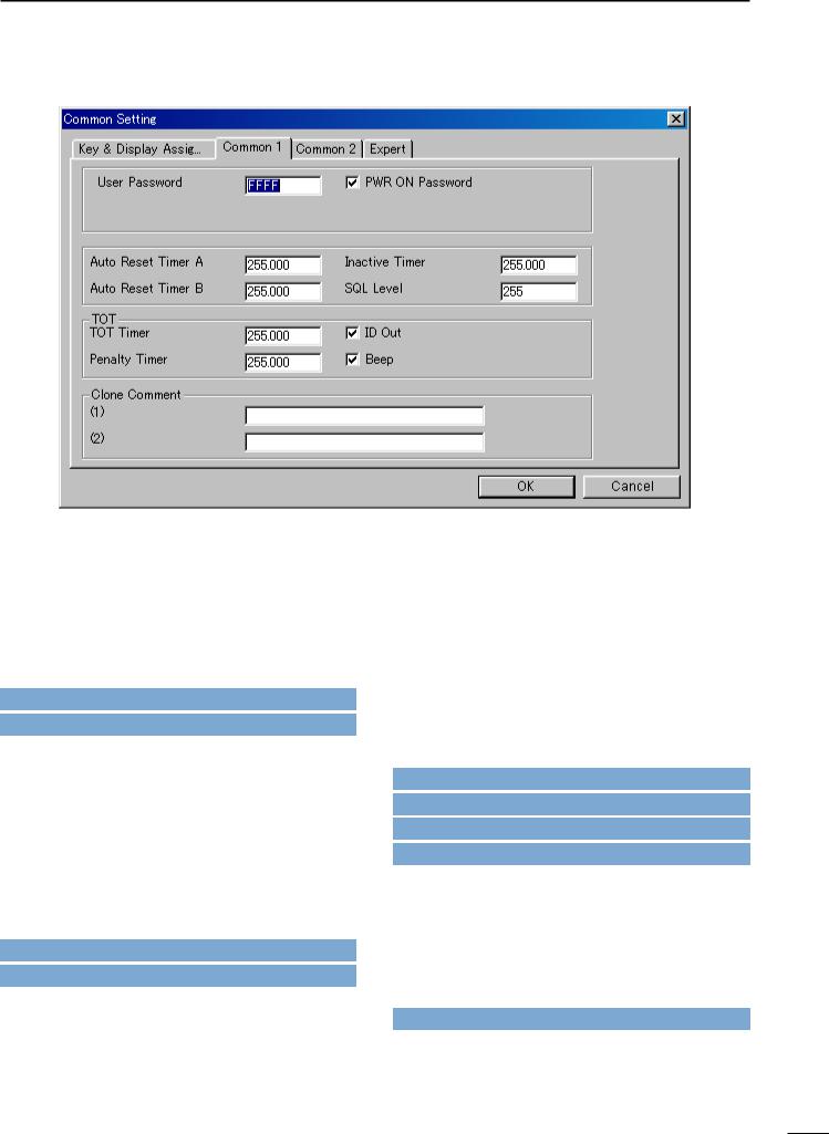
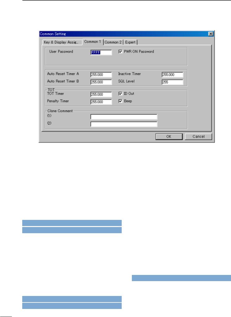
3-2 COMMON 1
• User Password
Enters up to a 4-digit user password for the power ON password function or for cancelling the “Stun” condition.
The power ON password function is specified in PWR ON Password as follows, and the “Stun” function is specified in Stun in 9-1/10-1 RX CODE CHANNEL (2- tone; p. 39/5-tone; p. 42).
Go to Stun— 2-tone
Go to Stun— 5-tone
• PWR ON Password
Click the check-box to activate the power ON password function.
It is necessary to enter the 4-digit password programmed in the User Password as above when checked. However, the password must be entered after receiving a “Stun” signal regardless of this setting.
The Stun condition is programmed in Stun in 9-1/10-1 RX CODE CHANNEL (2-tone; p. 39/5-tone; p. 42).
Go to Stun— 2-tone
Go to Stun— 5-tone
• Auto Reset Timer A, Auto Reset Timer B
Enter time period for returning the mute condition to the initial setting, specified in CH Mute in 5 MEMORY CH (PMR only; p. 31), and/or restarting the scan from a disappearing signal or when key operation is finished, if the power ON scan function is turned ON.
To turn OFF the Auto Reset function, enter “0 (zero)” to one of these settings. (“OFF” will be indicated)
The programmed settings are selected in Auto Reset in 4/5 MEMORY CH (LMR; p. 22/PMR; p. 31).
The power ON scan function is programmed in Power ON Scan in 8-2 SCAN SETTING (p. 37).
Go to CH Mute
Go to Auto Reset— LMR
Go to Auto Reset— PMR
Go to Power ON Scan
• Inactive Timer— PMR only
The entered time period acts as the Auto Reset Timer A,
Auto Reset Timer B as above.
This setting is used with the Auto Rest Timer A or Auto Rest Timer B, by selecting ‘Timer A Inact’ or ‘Timer B Inact’ in Auto Reset in 5 MEMORY CHANNEL (p. 31).
Go to Auto Reset— PMR
13
3 SCREEN MENU OPERATION—LMR
3-2 COMMON 1— continued
• SQL Level
Enter a value within 0–255 range for noise squelch threshold level adjustment.
• TOT— TOT Timer
Enters continuously transmittable time period (Time-out timer). Maximum time period is specified for 30, 60 or 180 sec. etc., according to country and local regulation.
The time-out timer function can be turned ON or OFF for each operating channel in TOT in 4/5MEMORY CHANNEL (LMR; p. 23/PMR; p. 31).
DO NOT set to only a few seconds, as transmitting will be impossible.
Go to TOT— LMR
Go to TOT— PMR
• TOT— ID Out (DTMF)/ID Out
Click the check-box to activate the automatic ID transmission capability.
-The “ ” mark appears when checked.
The function automatically transmits an ID code when the time-out timer activates, and just before transmission is inhibited.
The ID code is programmed in No. Log/ID in 6-1 DTMF AUTODIAL (p. 33) for LMR, and is specified in 5Tone Signaling— ID in 5 MEMORY CHANNEL (p. 29) for PMR operation.
Go to 6-1 DTMF AUTODIAL
Go to 5Tone Signaling— ID
• TOT— Penalty Timer
Enters un-transmittable time period for penalty when the continuously transmitted time has exceeded the specified time period programmed in TOT— TOT Timer as at left.
The TOT penalty time is the transmit inhibit period when the time-out timer is activated.
• TOT— Beep
Click the check-box to activate the warning beep output capability for TOT function.
-The “ ” mark appears when checked.
Emits warning beep 10 sec. before compulsory shut down of the transmission.
The transceiver emits warning beeps 10 sec. before, and the time-out timer activates when this setting is turned ON.
• Clone Comment— (1), (2)
Enters up to a 16-character text for quick identification of a transceiver’s content.
The programmed comment of the connected transceiver can be checked without reading all other existing programmed data. See t CLONE MENU— [Clone] in 2-1 MAIN SCREEN DESCRIPTION (p. 3).
Go to CLONE MENU— [Clone]
14
COMMON SETTING 3
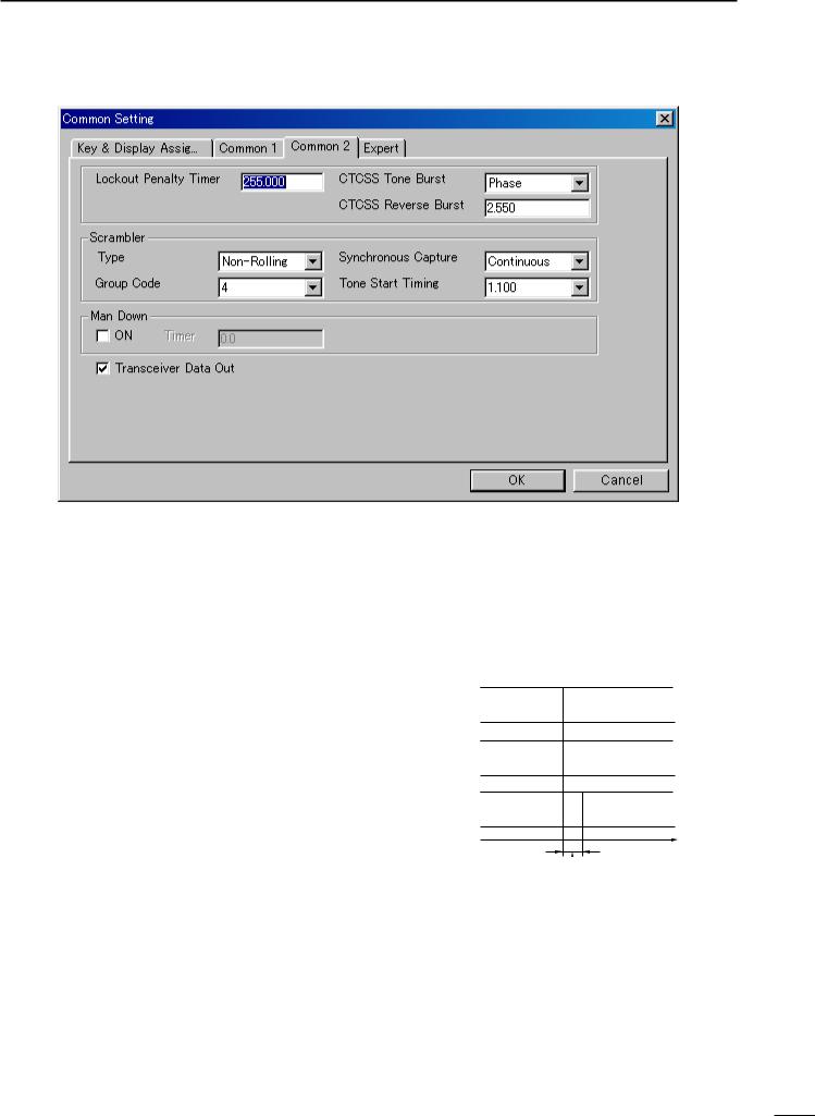
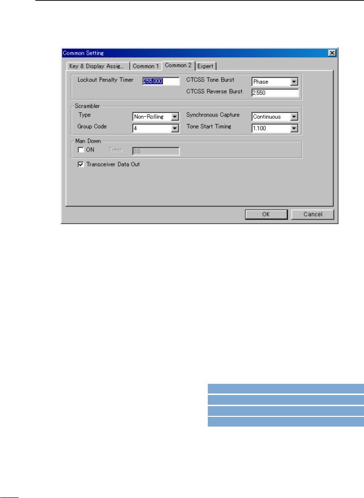
3-3 COMMON 2
• Lockout Penalty Timer
Enters un-transmittable time period for penalty when transmitted on a busy channel. The un-transmittable condition is kept for the programmed time period even if the channel is cleared.
The lockout penalty time is the transmit inhibit period when the user attempts to transmit while in a lockout condition. The transmission is inhibited for the lockout penalty time even when the lockout condition is cleared.
• CTCSS Tone Burst
Selects tone burst system from Notone and Phase. Notone: Un-modulates CTCSS encoder signal for the
specified time period, programmed in CTCSS Reverse Burst in this screen as at right. (This system is currently used.)
Phase : Reverses the phase of CTCSS encoder signal for the specified time period, programmed in CTCSS Reverse Burst in this screen as at right.
• CTCSS Reverse Burst
Enters time period for transmission delay with [PTT] switch operation and CTCSS signal.
The transceiver still transmits for the programmed period without the CTCSS encoder or with phase reversed CTCSS encoder signal after [PTT] is released. This removes the transceiver’s ‘Squelch delay’.
• CTCSS Reverse Burst
ON
PTT action
OFF
ON
Tone output
OFF
ON
RF power
output
OFF
Time
CTCSS Reverse Burst 
15
4 SCREEN MENU OPERATION—LMR
3-3 COMMON 2— Continued
• Scrambler— Type
Selects scrambler type from Rolling and Non-Rolling.
Selects ‘Rolling’ when the optional voice scrambler unit, UT-110 (#01), is installed, selects ‘Non-Rolling’ when UT-109 is installed.
UT-110 and UT-109 are not compatible due to different scrambling systems. However, UT-110 can be used instead of UT-109 by selecting ‘Non-Rolling’ type in this item
The Scrambler— Group Code as follows, must be programmed when UT-110 is used with the Rolling setting.
• Scrambler— Synchronous Capture
Selects synchronous capture mode from Standard and Continuous.
It is recommended that ‘Standard’ is selected for simplex/normal operation, ‘Continuous’ for repeater operation.
• Scrambler— Group Code
Selects scrambler group code from 1, 2, 3 and 4 when the optional voice scrambler unit, UT-110 (#01), is installed and ‘Rolling’ is selected in the Scrambler— Type as above.
Programming is not required when the optional voice scrambler unit, UT-109, is installed.
• Scrambler— Tone Start Timing
Selects reference tone signal delay time from OFF, 0.3sec., 0.6 sec. and 1.1 sec.
The setting is used to synchronize voice scrambling timing when the other stations/transceivers are in power save mode.
• Man Down— ON, Timer
Click the check-box, ON, and enter time period in the Timer column (25.5 sec. max.) to activate the man down function when the optional UT-113 MAN DOWN UNIT is installed.
The transceiver selects emergency channel and transmits an emergency signal automatically after passing the programmed time period when the transceiver has been left in a horizontal position.
The emergency channel is programmed in CH Atr in 4/5 MEMORY CHANNEL (LMR; p. 19/PMR; p. 24).
For the emergency signal—
LMR : DTMF code of Emergency, programmed in 6-1 DTMF AUTODIAL (p. 33), is used.
PMR : specified 5-tone/DTMF code selected in 5Tone Signaling— STN in 5 MEMORY CHANNEL
(p. 29) of the emergency channel.
Go to CH Atr— LMR
Go to CH Atr— PMR
Go to 6-1 DTMF AUTODIAL
Go to 5Tone Signaling— STN
• Transceiver Data Out
Click the check-box to enable the transceiver’s programmed data out capability for both using this software and cloning between transceivers.
-The “ ” mark appears when checked.
The setting does not inhibit data writing, therefore over writing data is still possible even when not checked.
16
COMMON SETTING 3
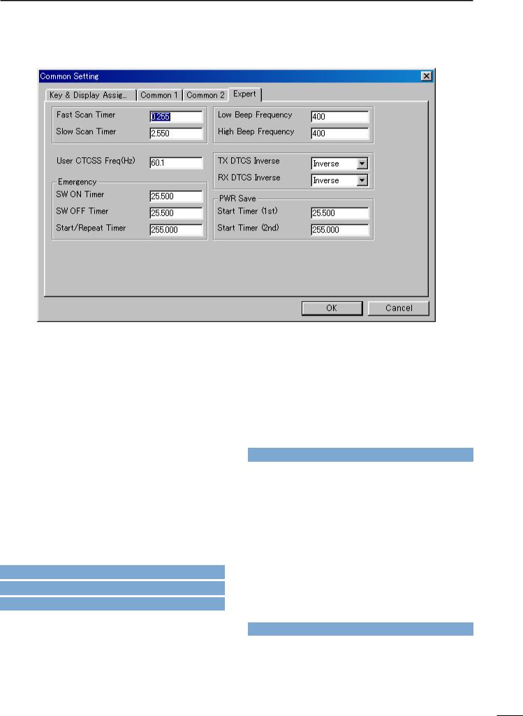
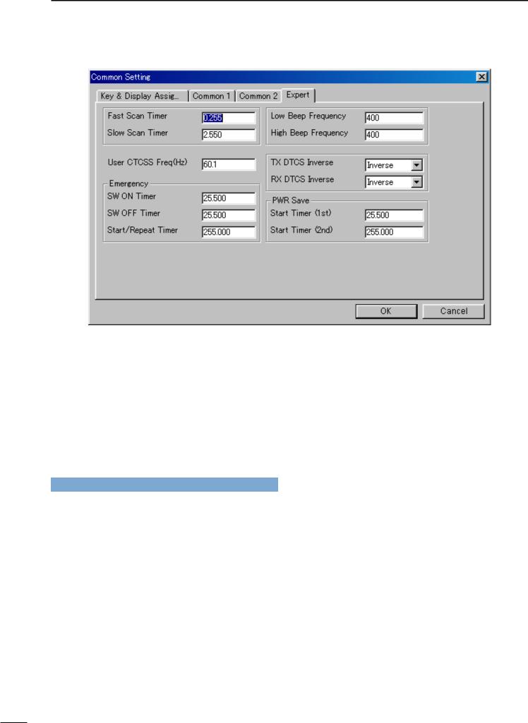
3-4 EXPERT
• Fast Scan Timer
Enters time period for scanning of each channel without CTCSS/DTCS programming.
An appropriate time is set by default and scan may not stop when setting a value less than the default.
• Slow Scan Timer
Enters time period for scanning of each channel with CTCSS/DTCS programming.
An appropriate time is set by default and scan may not stop when setting a value less than the default.
• User CTCSS Freq(Hz)
Programs additional customer/system own CTCSS frequency to the existing 51 CTCSS frequencies within 60.1 to 300.1 Hz range.
The programmed CTCSS frequency can be selected in
C.Tone— RX and TX in 4/5 MEMORY CHANNEL
(LMR; p. 20/PMR; p. 26), and RX, TX in 7 CONTINUOUS TONE (p. 35) by selecting ‘USER’.
Go to C.Tone— RX and TX— LMR
Go to C.Tone— RX and TX— PMR
Go to RX, TX
• Emergency— SW ON Timer
Enters time period for which [Emergency Repeat] or [Emergency Single] switch must be held to activate the emergency function.
Push and hold [Emergency Repeat] or [Emergency Single] switch for the programmed time period to make an emergency call.
[Emergency Repeat] or [Emergency Single] switch is assigned in 3-1 KEY & DISPLAY ASSIGN (p. 9).
Go to Emergency Repeat, Emergency Single
• Emergency— SW OFF Timer
Enters time period for which [Emergency Repeat] or [Emergency Single] switch must be held to cancel the emergency function.
Push and hold [Emergency Repeat] or [Emergency Single] switch for the programmed time period to cancel an emergency call before an emergency signal is transmitted.
However, once an emergency call is transmitted, the call cannot be cancelled regardless of this setting.
[Emergency Repeat] or [Emergency Single] switch is assigned in 3-1 KEY & DISPLAY ASSIGN (p. 9)
Go to Emergency Repeat, Emergency Single
17
3 COMMON SETTING
3-4 EXPERT— continued
• Emergency— Start/Repeat Timer
Enter the time periods for the emergency call delay and interval.
The transceiver makes an emergency call after passing the programmed time period when the emergency function is activated.
The transceiver transmits an emergency signal repeatedly at this interval until an “Emergency Cancel” code is received when [Emergency Repeat] is used.
[Emergency Repeat] or [Emergency Single] switch is assigned in 3-1 KEY & DISPLAY ASSIGN (p. 9).
Go to Emergency Repeat, Emergency Single
•Low Beep Frequency, High Beep Frequency
Enter beep audio frequency for each Low (for error) and High (for regular) beep within 400 to 2998 Hz range, respectively.
The nearest available frequency is selected automatically.
•TX DTCS Inverse
Selects the transmit DTCS code polarity.
In order for the transceiver to communicate using a DTCS code, the polarity of the transmitting transceiver’s transmit code must be the same as the polarity of the receiving transceiver’s receive code.
• RX DTCS Inverse
Selects the receive DTCS code polarity.
In order for transceivers to communicate using DTCS codes, the polarity of the receiving transceiver’s receive code must be the same as the polarity of the transmitting transceiver’s transmit code.
• PWR Save— Start Timer (1st), (2nd)
Enter the time period for the power saver function start timers within 0–25.5 sec. for the 1st, and 1–255 sec. or OFF (enter ‘OFF’, when ‘OFF’ is selected) for the 2nd timer.
The 1st timer must be set smaller than the 2nd timer, due to the fact that the 2nd timer/power saver function activates after the 1st timer/power saver. Otherwise the 1st timer does not activate. The 2nd timer will be set to ‘OFF’ when the UT-110 voice scrambler unit is installed. The long timer setting will be invalid.
18
|
4 |
|
MEMORY CHANNEL— LMR |
|
|
|
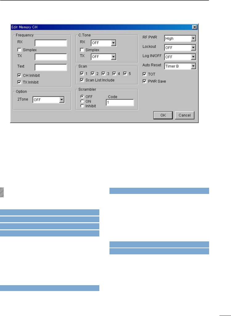
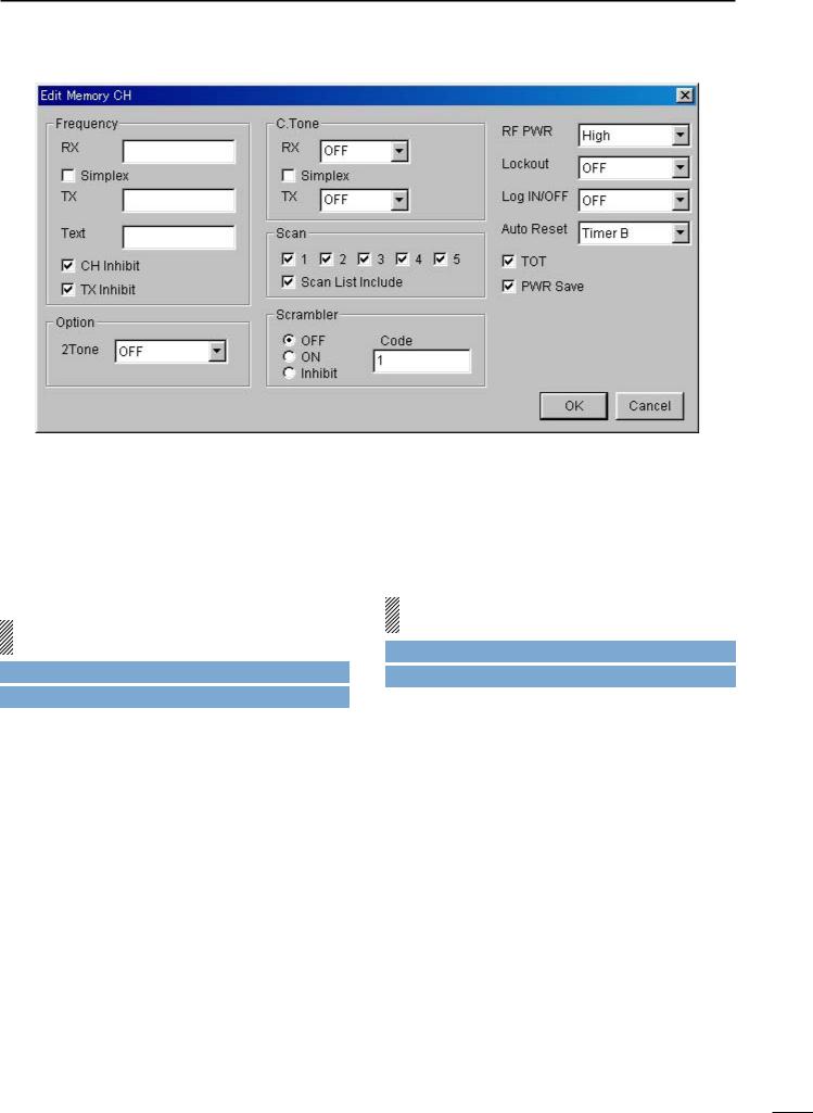
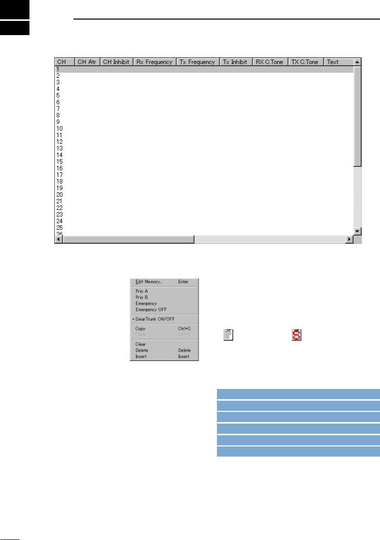
• CH Atr
Selects the channel attribution from Prio A, Prio B, Emergency, Emergency OFF and SmarTrunk ON/OFF.
Right click on the desired channel to open the submenu window as at right, then select the channel attribution.
A:Priority— “A” tagged channel becomes a priority channel A, simply recalled by pushing [Priority A] or [Priority A (Rewrite)] switch and also is automatically monitored during the priority scan. When [Priority A (Rewrite)] switch is assigned, priority channel A can be re-assigned by pushing [Priority A (Rewrite)] switch for 1 sec..
B:Priority— “B” tagged channel becomes a priority channel B, simply recalled by pushing [Priority B] switch.
E:Emergency— “E” tagged channel becomes an emergency channel, immediately recalled and sends an emergency signal by pushing [Emergency Single] or [Emergency Repeat] switch, or when the man down function is activated. Only 1 channel can be set.
Emergency OFF— Regular channel.
SmarTrunk ON/OFF— Specifies the selected bank for SmarTrunk operation.
This selection appears only when either 8CH*5Bank, 16CH*2Bank + 8CH or 20CH*2Bank type is selected in the BANK menu (p. 3) or, double click the bank item in the Bank Setting in Memory Channel folder indicated in the Tree View Screen (p. 4).
SmarTrunk specified bank/s, the bank item in the Memory Channel folder, displayed in the Tree View Screen, changes from regular to SmarTrunk type as follows for easy recognition.
: Regular type |
: SmarTrunk type |
||
[Priority A], |
[Priority A (Rewrite)], |
[Priority B], |
|
[Emergency Single] and [Emergency Repeat] switches are assigned in 3-1 KEY & DISPLAY ASSIGN (pgs. 7, 9). The man down function is specified in Man Down— ON, Timer in 3-3 COMMON 2 (p. 16)
Go to u BANK MENU
Go to w Memory Channel
Go to Prio A, Prio B
Go to Prio A (Rewrite)
Go to Emergency Single, Emergency Repeat
Go to Man Down— ON, Timer
The channel attribution can only be set on the Memory Channel Screen as shown above. (Cannot be set in the Edit window.) However, the other items are programmable in the Edit window only.
The Edit window appears by pushing the [Enter] key, double clicking or selecting in the sub menu window via the right click operation with the mouse on the desired channel.
19
4 MEMORY CHANNEL— LMR
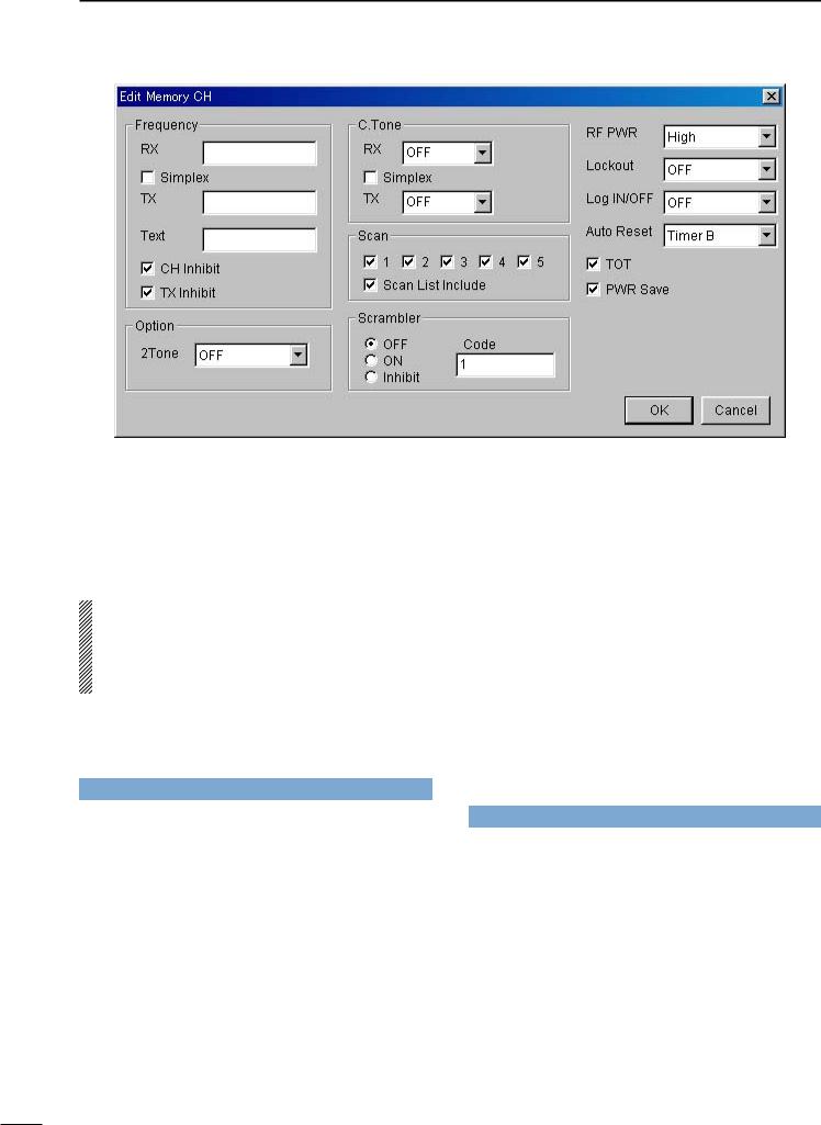
• Frequency— RX, TX
Enter receive and transmit frequencies within the following frequency range in either 5, 6.25 or 7.5 kHz steps* for the RX and TX boxes, respectively.
IC-F3GT/GS : 136–150, 146–174 MHz IC-F4GT/GS : 400–430, 440–470, 470–500,
490–512 MHz
*according to version
When no receive frequency is entered, other items cannot be programmed in the channel.
When SmarTrunk ON/OFF is selected for the editing bank in CH Atr (p. 19), operating frequencies must be programmed from channel 1 without a blank.
When programming a simplex channel (transmit and receive frequencies are the same), checks the simplex check-box for instant setting after receive frequency is programmed as follows.
Go to CH Atr
• Frequency— Simplex
Click the check-box when the same frequency as the receive is used for the transmit.
-The “ ” mark appears in the check-box when checked.
• Frequency— Text
Enter up to a 7-character text in the Text box for memory name, channel usage, etc.
The usable characters are A–Z, 0–9, $, ’, (, ), –, /, <, =, >, @, [, \, ], _, {, |, } and ~.
When no text is entered, the channel number is indicated.
• Frequency— CH Inhibit
Click the check-box when the channel is to be inhibited.
The channel never appears on the transceiver, even if all the other items are programmed when the channel is inhibited.
-The “ ” mark appears in the check-box when checked.
• Frequency— TX Inhibit
Click the check-box when transmission inhibit is necessary.
-The “ ” mark appears when checked.
• Option— 2Tone
Selects 2-Tone code channel for reception with transceiver’s action when a matched 2-tone code is received from OFF, 1, 2 and 3.
OFF : Nothing changes.
1, 2, 3 : Activates a specified channel 1, 2 or 3 as programmed in the 9-1 RX CODE CHANNEL
(p. 38).
Go to 9-1 RX CODE CHANNEL
• C.Tone— RX, TX
Selects desired CTCSS frequency from the list or enter a 3-digit DTCS code with polarity, N (Normal) or I (Inverse), for receive and transmit in the RX and TX boxes, respectively.
When programming the same continuous tone as the receive for the transmission, checks the simplex check-box for instant setting after receive frequency is programmed as follows.
• C.Tone— Simplex
Click the check-box when the same continuous tone as the receive is used for the transmission.
-The “ ” mark appears in the check-box when checked.
20
MEMORY CHANNEL— LMR 4
• Scan— 1–5
Click the check-box to the channel included into the desired scan list (scanning group) 1–5.
Only the checked channels in the same scan list are scanned when [Scan A] or [Scan B] switch is pushed.
-The “ ” mark appears in the check-box when checked.
The scan list (scanning group) is selectable via [CH Up] or [CH Down] switches, after [Scan A] or [Scan B] switch is pushed for 1 sec..
The scanning conditions for each scan list are specified in 8 SCAN LIST (pgs. 36–37).
When SmarTrunk ON/OFF is selected for the editing bank in CH Atr (p. 19), all boxes must be blank.
[CH Up], [CH Down], [Scan A] or [Scan B] switch is assigned in 3-1 KEY & DISPLAY ASSIGN (p. 6).
Go to 8 SCAN LIST
Go to CH Atr
Go to CH Up, CH Down
Go to Scan A, Scan B
• Scan— Scan List Include
Click the check-box to enable scanning channel modification from the transceiver’s keypad.
The desired channel can be added or deleted to/from the selected scan list by pushing [Scan Add/Del(Tag)] switch.
[Scan Add/Del(Tag)] switch is assigned in 3-1 KEY & DISPLAY ASSIGN (p. 7).
Go to Scan Add/Del(Tag)
• Scrambler— OFF, ON, Inhibit
Click to select voice scrambling function initial setting from OFF, ON and Inhibit.
When OFF or ON is selected, the voice scrambling function can be manually switched with the [Scrambler] switch, however, the function cannot be manually switched ON when Inhibit is selected.
An optional UT-109 or UT-110 VOICE SCRAMBLER UNIT is required.
The [Scrambler] switch is assigned in 3-1 KEY & DISPLAY ASSIGN (p. 10).
Go to Scrambler
• Scrambler— Code
Enter voice scrambling code within 1–32 using UT-109 or UT-110 with ‘Non-Rolling’ selection or within 1–255 using UT-110 with ‘Rolling’ selection installed.
In addition, the Scrambler— Group Code in 3-3 COMMON 2 (p. 16) must be programmed when UT110 is installed and ‘Rolling’ is selected in
Scrambler— Type in 3-3 COMMON 2 (p. 16).
Go to Scrambler— Group Code
Go to Scrambler— Type
21
4 MEMORY CHANNEL— LMR
• RF PWR
Selects transmit output power for initial setting from High and Low.
The selected output power setting for each channel can be switched to either temporary or permanent operation, according to the setting in the RF Power Selection in 3-1 KEY & DISPLAY ASSIGN (p. 11) via [High/Low] switch.
The [High/Low] switch is assigned in the 3-1 KEY & DISPLAY ASSIGN (p. 7)
Go to RF Power Selection
Go to High/Low
• Lock out
Selects transmission lock out (temporary transmission inhibit) capability from OFF, Busy and Rpt (Repeater).
OFF |
: No restriction for receiving a signal. |
Busy |
: [PTT] switch cannot be activated while the |
|
operating channel/repeater is in use. |
Rpt |
: [PTT] switch can be activated while receiving |
|
a signal with matched CTCSS (or DTCS) |
|
tone or no signals. |
In addition, [PTT] switch is not activated for an extra time period in the case of when the lockout penalty timer, programmed in the Lockout Penalty Timer in 3- 3 COMMON 2 (p. 15), is activated, even if the transceiver in a transmittable condition.
Go to Lockout Penalty Timer
• Log IN/OFF
Selects automatic ID transmission condition in relation with [PTT] from L-IN, L-OFF, Both and OFF.
OFF |
: No ID is transmitted with [PTT]. |
L-IN |
: ID is transmitted each time [PTT] is pushed. |
L-OFF: ID is transmitted each time [PTT] is released. Both : ID is transmitted each time [PTT] is pushed
and released.
Log/ID code is used as the ID code, programmed in 6- 1 DTMF AUTODIAL (p. 33).
When SmarTrunk ON/OFF is selected for the editing bank in CH Atr (p. 19), “OFF” must be selected.
Go to 6-1 DTMF AUTODIAL
Go to CH Atr
• Auto Reset
Selects reset timer from Timer A and Timer B for restarting scanning when the power ON scan function is activated
Timer A, Timer B:
Restarts scanning after specified time period (Timer A or Timer B) has passed from a disappearing signal or key operation is finished.
The time period of Timer A and Timer B are programmed in the Auto Reset Timer A, Auto Reset Timer B in 3-2 COMMON 1 (p. 13), respectively.
To turn OFF the function, select the timer which OFF (0 sec.) is programmed.
The power ON scan function is specified in the Power ON Scan in 8-2 SCAN SETTING (p. 37).
Go to Auto Reset Timer A, Auto Reset Timer B Go to Power ON Scan
22
MEMORY CHANNEL— LMR 4
• TOT
Click the check-box to activate the time-out timer function.
-The “ ” mark appears when TOT function is activated.
Continuously transmittable time is limited by the timer during activation. However, time-out timer must be activated due to local regulation, in some countries.
The time period is programmed in the TOT— TOT Timer in 3-2 COMMON 1 (p. 14).
When SmarTrunk ON/OFF is selected for the editing bank in CH Atr (p. 19), “OFF” must be selected.
Go to TOT— TOT Timer
Go to CH Atr
• PWR Save
Click the check-box to activate the power save function.
-The “ ” mark appears when the power save function is activated.
The power save start times are programmed in the
PWR Save— Start Timer (1st), (2nd) in 3-4 EXPERT
(p. 18).
When SmarTrunk ON/OFF is selected for the editing bank in CH Atr (p. 19), “OFF” must be selected.
Go to PWR Save— Start Timer (1st), (2nd)
Go to CH Atr
23
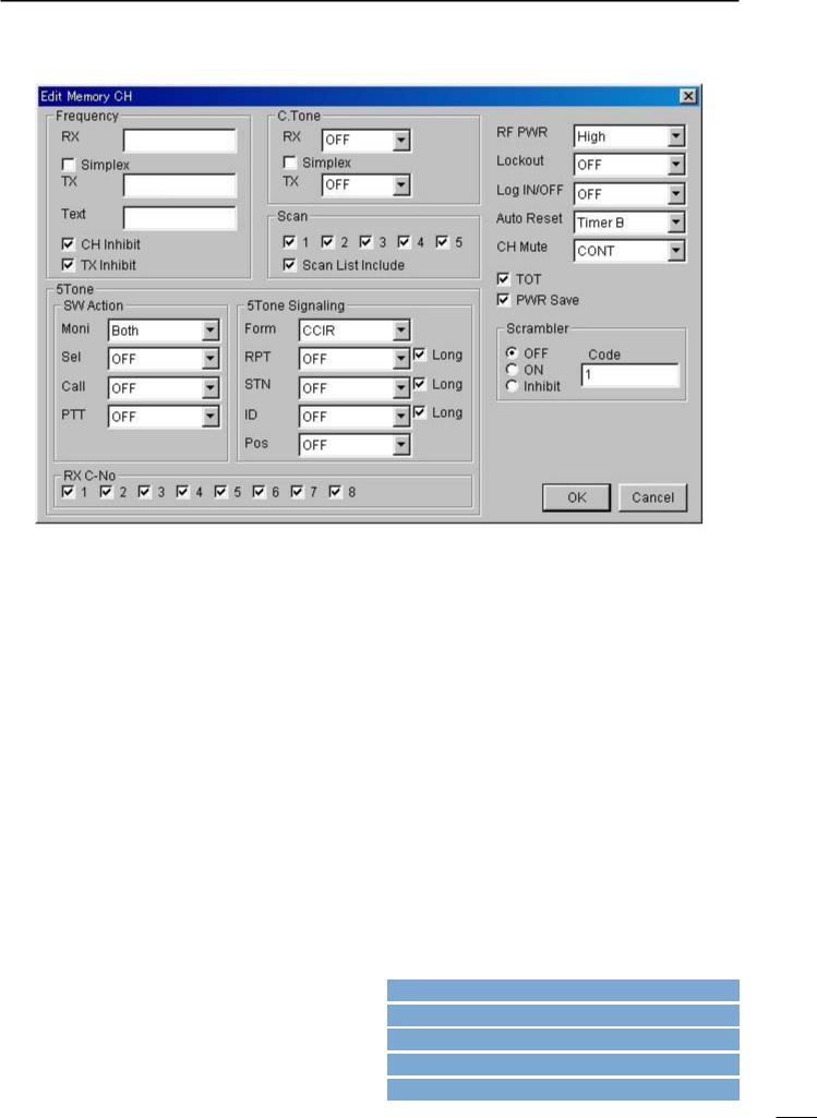
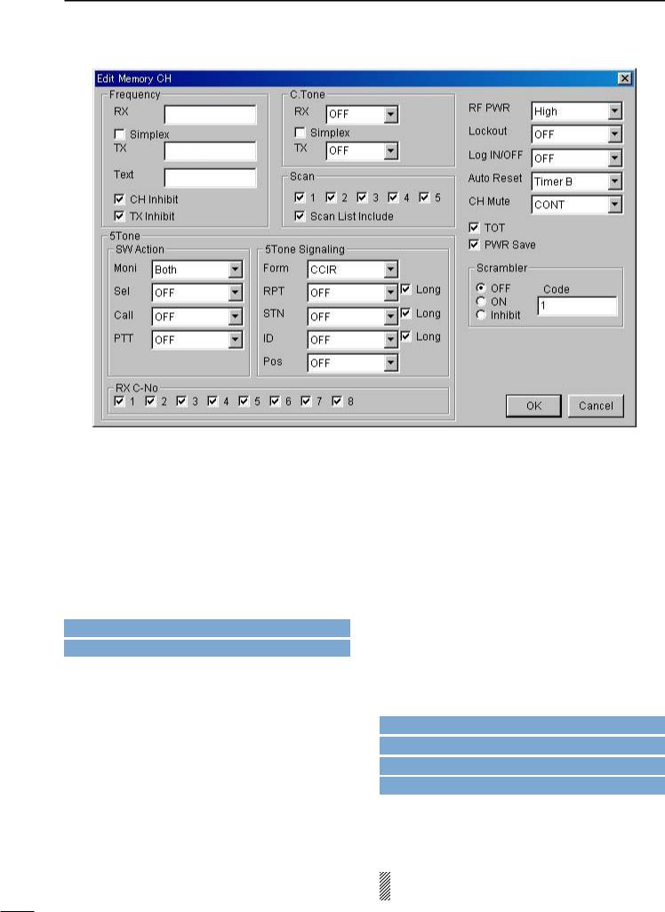
5 MEMORY CHANNEL— PMR
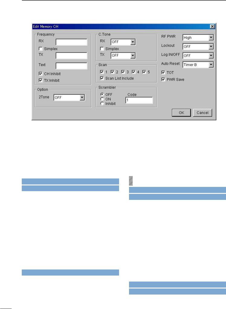
• CH Atr
Selects the channel attribution from Prio A, Prio B, Emergency, Emergency OFF and SmarTrunk ON/OFF.
Right click on the desired channel to open the submenu window as at right, then select the channel attribution.
A:Priority— “A” tagged channel becomes a priority channel A, simply recalled by pushing [Priority A] or [Priority A (Rewrite)] switch and also is automatically monitored during the priority scan. When [Priority A (Rewrite)] switch is assigned, priority channel A can be re-assigned by pushing [Priority A (Rewrite)] switch for 1 sec..
B:Priority— “B” tagged channel becomes a priority channel B, simply recalled by pushing [Priority B] switch.
E:Emergency— “E” tagged channel becomes an emergency channel, immediately recalled and sends an emergency signal by pushing [Emergency Single] or [Emergency Repeat] switch, or when the man down function is activated. Only 1 channel can be set.
Emergency OFF— Regular channel.
SmarTrunk ON/OFF— Specifies the selected bank for SmarTrunk operation.
This selection appears only when either 8CH*5Bank, 16CH*2Bank + 8CH or 20CH*2Bank type is selected in the BANK menu (p. 3) or, double click the bank item in the Bank Setting in Memory Channel folder indicated in the Tree View Screen (p. 4).
SmarTrunk specified bank/s, the bank item in the Memory Channel folder, displayed in the Tree View Screen, changes from regular to SmarTrunk type as follows for easy recognition.
: Regular type |
: SmarTrunk type |
||
[Priority A], |
[Priority A (Rewrite)], |
[Priority B], |
|
[Emergency Single] and [Emergency Repeat] switches are assigned in 3-1 KEY & DISPLAY ASSIGN (pgs. 7, 9). The man down function is specified in Man Down— ON, Timer in 3-3 COMMON 2 (p. 16).
Go to u BANK MENU
Go to w Memory Channel
Go to Prio A, Prio B
Go to Prio A (Rewrite)
Go to Emergency Single, Emergency Repeat
Go to Man Down— ON, Timer
The channel attribution can only be set on the Memory channel Screen as shown above. (Cannot be set in the Edit window.) However, the other items are programmable in the Edit window only.
The Edit window appears by pushing the [Enter] key, double clicking or selecting in the sub menu window via the right click operation with the mouse on the desired channel.
24

SCREEN MENU OPERATION— PMR 5
• Frequency— RX, TX
Enter receive and transmit frequencies within the following frequency range in either 5, 6.25 or 7.5 kHz steps* for the RX and TX boxes, respectively.
IC-F3GT/GS : 136–150, 146–174 MHz IC-F4GT/GS : 400–430, 440–470, 470–500,
490–520 MHz
*according to version
When no receive frequency is entered, other items cannot be programmed in the channel.
When SmarTrunk ON/OFF is selected for the editing bank in CH Atr (p. 24), operating frequencies must be programmed from channel 1 without a blank.
When programming a simplex channel (transmit and receive frequencies are the same), checks the simplex check-box for instant setting after receive frequency is programmed as follows.
Go to CH Atr
• Frequency— Simplex
Click the check-box when the same frequency as the receive is used for the transmit.
-The “ ” mark appears in the check-box when checked.
• Frequency— Text
Enter up to a 7-character text for memory name, channel usage indication, etc..
The usable characters are A–Z, 0–9, $, ’, (, ), –, /, <, =, >, @, [, \, ], _, {, |, } and ~.
When no text is entered, the channel number is indicated.
The programmed text is indicated during operation or briefly indicated after operating channel selection when ‘MR CH’ or ‘MR CH+TX CODE CH’ is selected in
MR/Code Display in 3-1 KEY & DISPLAY ASSIGN
(p. 12).
Go to MR/Code Display
• Frequency— CH Inhibit
Click the check-box when the channel is to be inhibited.
The channel never appears on the transceiver, even if all the other items are programmed when the channel is inhibited.
-The “ ” mark appears in the check-box when checked.
• Frequency— TX Inhibit
Click the check-box when transmission inhibit is necessary.
-The “ ” mark appears when checked.
25

5 SCREEN MENU OPERATION— PMR
• C.Tone— RX, TX
Selects desired CTCSS frequency from the list or enter a 3-digit DTCS code with polarity, N (Normal) or I (Inverse), for receive and transmit in the RX and TX boxes, respectively.
When programming the same continuous tone as the receive for the transmission, checks the simplex check-box for instant setting after receive frequency is programmed as follows.
• C.Tone— Simplex
Click the check-box when the same continuous tone as the receive is used for the transmission.
-The “ ” mark appears when checked.
• Scan— 1–5
Click the check-box to the channel included in to the desired scan list (scan group) 1–5.
Only the checked channels in the same scan list are scanned when [Scan A] or [Scan B] switch is pushed.
-The “ ” mark appears when checked.
The scan list (scanning group) is selectable via [CH Up] or [CH Down] switches, after [Scan A] or [Scan B] switch is pushed for 1 sec..
The scanning conditions for each scan list are specified in 8 SCAN LIST (pgs. 36–37).
When SmarTrunk ON/OFF is selected for the editing bank in CH Atr (p. 24), all boxes must be blank.
[CH Up], [CH Down], [Scan A] or [Scan B] switch is assigned in 3-1 KEY & DISPLAY ASSIGN (p. 6).
Go to 8 SCAN LIST
Go to CH Atr
Go CH Up, CH Down
Go to Scan A, Scan B
• Scan— Scan List Include
Click the check-box to enable scanning channel modification from the transceiver’s key.
The desired channel can be added or deleted to/from the selected scan list by pushing [Scan Add/Del(Tag)] switch.
[Scan Add/Del(Tag)] switch is assigned in 3-1 KEY & DISPLAY ASSIGN (p. 7).
Go to Scan Add/Del(Tag)
26
SCREEN MENU OPERATION— PMR 5
• SW Action— Moni
Selects [Moni(Audi)] switch action from OFF, Aud, In A, In A+R1, In A+R2, Both, Both+R1 and Both+R2.
OFF : Releases both noise and CTCSS/DTCS squelch mute while pushing and holding [Moni(Audi)] switch. There is no audio output when 5-tone mute is activated on the channel.
Aud : Releases the 5-tone mute only when ‘SGL’ is selected in CH Mute (p. 31) in this screen, by pushing [Moni(Audi)] switch for 1 sec..
Both CTCSS/DTCS and noise squelch mutes are released (audio is emitted) while pushing and holding [Moni(Audi)] switch when 5-tone mute is released or ‘CONT’ is selected in CH Mute (p. 31) in this screen.
In A : Mutes the 5-tones when ‘SGL’ is selected in CH Mute (p. 31) in this screen by pushing [Moni(Audi)] switch.
Both CTCSS/DTCS and noise squelch mutes are released (audio is emitted) while pushing and holding [Moni(Audi)] switch while 5-tone mute is activated.
In A+R1, In A+R2:
In addition to the ‘In_A’ condition as above, a reset code 1 or 2 is automatically transmitted when call transmission is performed or 5-tone mute is activated by pushing [Moni(Audi)] switch.
Both : Mutes the 5-tones when ‘SGL’ is selected in CH Mute (p. 31) in this screen by pushing [Moni(Audi)] switch.
Releases 5-tone mute when ‘SGL’ is selected in CH Mute (p. 31) in this screen by pushing [Moni(Audi)] switch for 1 sec.
Releases all mute controls and emits audio while pushing and holding [Moni(Audi)] switch.
Both+R1, Both+R2:
In addition to the ‘Both’ condition as above, a reset code 1 or 2 is automatically transmitted when call transmission is performed via [Call] switch or 5-tone mute is activated by pushing [Moni(Audi)] switch.
The [Moni(Audi)] and [Call] switches are assigned in the 3-1 KEY & DISPLAY ASSIGN (pgs. 7, 8).
The reset code 1 and 2 are programmed in 10-2 TX CODE CHANNEL (p. 43), and channels 32 (reset code 1) and 31 (reset code 2) are used, respectively.
The mute condition will be returned to initial condition when the Auto Reset timer is activated, specified in Auto Reset in this screen (p. 31).
Go to CH Mute
Go to Moni(Audi)
Go to Call
Go to 10-2 TX CODE CHANNEL
Go to Auto Reset
27
5 SCREEN MENU OPERATION— PMR
• SW Action— Sel
Selects mute condition after memory channel selection from OFF, Aud and In A.
OFF |
: Dose not change even when selecting |
|
memory or TX code channel. |
Aud |
: Releases the 5-tone mute when ‘SGL’ is |
|
selected in CH Mute (p. 31) in this screen. |
In A |
: Mutes the 5-tones when ‘SGL’ is selected in |
|
CH Mute (p. 31) in this screen. |
The mute condition will be returned to initial condition when the Auto Reset timer is activated, specified in Auto Reset in this screen (p. 31).
Go to CH Mute
Go to Auto Reset
• SW Action— Call, PTT
Selects mute condition after [Call] and [PTT] switches action from Aud and OFF.
OFF |
: Does not change when transmitting with |
|
[Call]/[PTT] transmission. |
Aud |
: Releases the 5-tone mute when ‘SGL’ is |
|
selected in CH Mute (p. 31) in this screen |
|
after any [Call]/[PTT] transmission. |
Select OFF for both the SW Action— Call and PTT, when the ABC— Aud in 10-2 TX CODE CHANNEL
(p. 44) is activated, and select OFF for the SW Action— PTT, when the PTT Call at Inaudible in 10-5 5TONE SETTING (p. 48) is activated.
The [Call] switch is assigned in the 3-1 KEY & DISPLAY ASSIGN (p. 8).
The mute condition will be returned to initial condition when the Auto Reset timer is activated, specified in Auto Reset in this screen (p. 31).
Go to CH Mute
Go to Go to ABC— Aud
Go to Call
Go to PTT Call at Inaudible
• 5Tone Signaling— Form
Selects 5-tone system format from USER, CCIR, ZVEI1, ZVEI2, DZVEI, EEA, EEA2, DAPL, EIA and DTMF.
When the DTMF decoder operation is required (UT108 must be installed), select DTMF in this item.
28
Loading...