


TE
TXCi
TC 250 2011 - TC 250i 2011 I.E. USA
CARATTERISTICHE - USO - MANUTENZIONE
Dove non diversamente specificato, i dati e le prescizioni si riferiscono a tutti i modelli.
Unless specified, data and presciption are referred to all t he models.
Lorsque non différemment indiqué, les donneé et les instructions se réfèrent à tous les modèles.
Wo nicht anders ausdrücklich angegeben, beziehen sich die Daten und die Vorschriften auf alle Modelle.
Donde no especificado, los datos y resenas se refieren a todos los modelos.
TC
TE 250 - 310 2011 I.E.
TEi 250 2011 I.E. USA
TXCi 250 2011 I.E. USA
SPECIFICATIONS - OPERATION - MAINTENANCE
CARACTERISTIQUES - UTILISATION - ENTRETIEN
MERKMALE - GEBRAUCH - WARTUNG
CARACTERISTICAS - USO - MANTENIMIENTO
IT
IT - 1

ENGLISH
EN
EN - 1
PRESENTATION
Welcome to the Husqvarna motorcycling Family!
Your new Husqvarna motorcycle is designed and manufactured to be the finest in its field.
The instructions in this book have been prepared to provide
a simple and understandable guide for your motorcycle’s
operation and care.
Follow the instructions carefully to obtain maximum performance and your personal motorcycling pleasure. Your
owner’s manual contains instructions for owner care and
maintenance.
The main work of repair or maintenance requires the attention of a skilled mechanic and the use of special tools
and equipment.
Your Husqvarna dealer has the facilities, experience and original parts necessary to properly render this valuable service.
This “Owner’s Manual” is part and parcel of the motorcycle, hence, this had to
remain with the motorcycle even when
sold to another user.
This motorcycle uses components designed thanks to systems and state of the art technologies which are thereafter tested in competition.
In competition motorcycles, every detail is verified after each
race in order to always guarantee better performance. For
correct functioning of the vehicle, it is necessary to follow the
maintenance and control table found on Appendix A.
IMPORTANT NOTICES
1) The TC and TXCi models are guarante-
ed COMPETITION motorcycles exempt from
functional defects, the suggested maintenance table for competition use is shown on
Appendix A.
2) TE vehicles are STREET LEGAL motorcycles (with LIMITED POWER ENGINE); they
are guaranteed exempt from functional defects and covered with legal guarantee, if the
STANDARD CONFIGURATION is maintained
and the suggested maintenance table, shown
on Appendix A is observed.
If TE vehicles are transformed in COMPETITION MOTORCYCLES (with FULL POWER ENGINE), the suggested maintenance table for
competition use is shown on Appendix A.
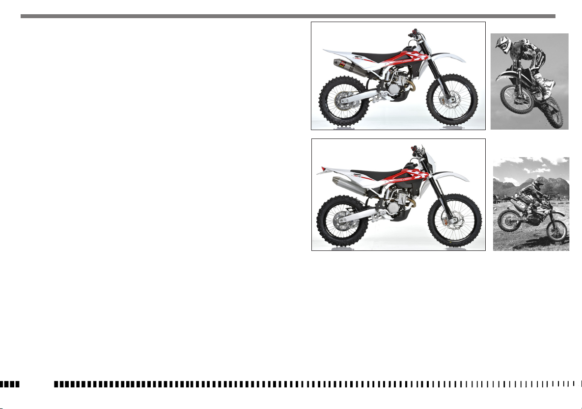
MOTOCROSS
ENDURO
EN - 2

IMPORTANT
The reference for recognition of the guarantee will be the MOTORCYCLE CONFIGURATION, as shown below:
A) STANDARD MOTORCYCLE, STREET LEGAL: with LIMITED POWER ENGINE
B) COMPETITION MOTORCYCLE, RACING USE: with FULL POWER
ENGINE
This motorcycles was not designed for long
trips with the engine always at maximum
rpm as can occur whilst travelling on roads
or highways. Long trips at full throttle can
cause severe damage to the engine.
This motorcycles is setup for competition use
and therefore guarantees maximum performance with the rider alone. It is thereby not
recommended to use the vehicle on circuits
or off-road with a passenger.
ALWAYS keep in mind that these motorcycles have been designed strictly for competition use, that is, for conditions of usage
very different from those presented on the road.
ALWAYS keep in mind that these motorcycles
have been designed strictly for competition
use, that is, for conditions of usage very different from those presented on the road.
In order to maintain the vehicle’s “Guarantee of Functionality”, the client must follow
the maintenance program indicated in the
user’s manual by carrying out maintenance
checks at authorized HUSQVARNA dealers.
The cost for substituting parts and for the
labour necessary in order to respect the
maintenance plan, is charged to the client.
NOTE: the guarantee is EXTINGUISHED in the
case where the motorcycle is rented.
Important Notice
Read this manual carefully and pay special attention to statements preceeded by the following words:
Warning*: Indicates a possibility of severe
personal injury or loss of life if instructions
are not followed.
Caution*: Indicates a possibility of personal
injury or equipment damage if instructions
are not followed.
Note*: Gives helpful information.
Parts Replacement
When parts replacement is required, use only Husqvarna ORIGINAL parts.
Warning*: After an upset, inspect the motorcycle carefully. Make sure that the throttle,
brake, clutch and all other systems are undamaged. Riding with a damaged motorcycle
can lead to a serious crash.
Warning*: Never attempt to start or operate
your motorcycle unless you are wearing appropriate protective clothing. Always wear a
motorcycle helmet, motorcycle boots, gloves,
goggles and other appropriate protective
clothing.
Warning*: This motorcycle is a state of the
art competition bike. Do not attempt to start
or ride this motorcycle until you have received expert instruction and are in excellent
physical condition.
PRECAUTIONS FOR CHILDREN
WARNING
• Park the vehicle where it is unlikely to
be bumped into or damaged. Even slight or
involuntary bumps can cause the vehicle to
topple over, with subsequent risk of serious
harm to people or children.
• To prevent the vehicle from tipping over,
never park it on soft or uneven ground, nor
on asphalt strongly heated by the sun.
•Engine and exhaust pipes become very hot
during riding. Always park your motorcycle
where people or children can not easily reach these parts, in order to avoid serious
burns.
EN
EN - 3

TABLE OF CONTENTS
PRESENTATION
......................................................................2
IMPORTANT NOTICES
IDENTIFICATION DATA
CONTROL LOCATION ...............................................................6
TECHNICAL DATA
LUBRICATION TABLE, SUPPLIES
CONTROLS
.............................................................................9
APPENDIX
............................................................................54
PRE-DELIVERY INSPECTION
ALPHABETICAL INDEX
.............................................................2
............................................................5
...................................................................7
..............................................8
...................................................55
...........................................................56
Page
PERIODIC MAINTENANCE -ADJUSTMENT .................. Appendix
•References to the “left” or “right” of the motorcycle are in
Note
the sense of a person facing forwards.
•Z: number of teeth
• A: Austria
AUS: Australia
B: Belgium
BR: Brazil
CDN: Canada
CH: Switzerland
D: Germany
A
E: Spain
F: France
FIN: Finland
GB: Great Britain
I: Italy
J: Japan
USA: United States of America
•Where not specified, all the data and the instructions are
referred to any and all Countries.
EN - 4
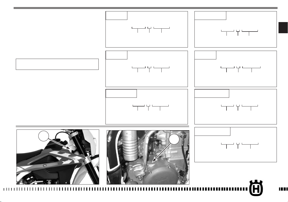
IDENTIFICATION DATA
The engine number is printed on the upper side of the engine
case, whereas the frame number is printed on the steering tube.
Always state the number stamped on the frame
(and write it on this booklet), when placing orders for spare
parts, or when asking for informations about your motorcicle.
TE 250
ZKHA300AABV000001
(l) (▲) (♦)
TE 310 USA
ZKHKCEDG#BV000001
EN
(l) (▲) (♦)
FRAME NUMBER
VEHICLE IDENTIFICATION NUMBER (V.I.N.)
The full 17 digit serial, or Vehicle Identification Number, is stamped on the steering head tube (R.H. side).
(l) = Model designation
(▲) = Model Year (2011)
♦
) = Progressive no.
(
1. Frame serial number
2. Engine serial number
1
TE 310
ZKHA301AABV000001
TE 250 USA
ZKHKCECF#BV000001
(l) (▲) (♦)
(l) (▲) (♦)
TC 250
ZKHA300AABV050001
(l) (▲) (♦)
TC 250 - USA
ZKHTC253#BV000001
(l) (▲) (♦)
TXCi 250 - USA
2
ZKHTX250#BV000001
(l) (▲) (♦)
EN - 5
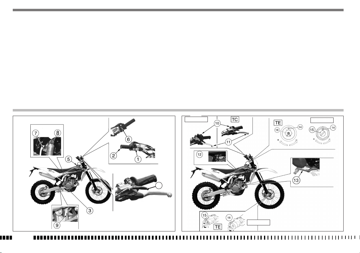
CONTROL LOCATION
1. Front brake lever
2. Throttle grip
3. Rear brake control pedal
4. Choke
5. Fuel tank filler cap
6. R.H. commutator (engine electric start TE - TXCi)
7.Rear shock absorber spring preload adjustment
8. Rear shock absorber compression damper adjustment (low and high damping speeds)
9. Rear shock absorber extension damper adjustment
10. L.H. commutator (TE)
10. Engine stop button (TC)
11.Clutch control lever
12. Fuel cock (TE - TXCi)
13. Gearbox control pedal
14. Air bleeding screw on front fork leg
15. Compression damper adjustment
16. Extension damper adjustment
EN - 6
TC - TXC
4
TC - TXC
TC - TXC

TECHNICAL DATA
ENGINE
Type............................................single cylinder, 4 stroke
Cooling ............ liquid, with electric fan on TE-TXCi models
TC-TE-TXCi 250
Bore ............................................................................. 3,11 in.
Stroke .........................................................................2.00 in.
Displacement
.....................................................15,22 cu. in.
Compression ratio .................................................13,6:1
TE 310
Bore .............................................................................3,23 in.
..........................................................................2,26 in.
Stroke
Displacement
Compression ratio ..................................................
......................................................18,46 cu. in.
12,5:1
Starting (TC) .... kick start (with automatic decompressor)
Starting (TE-TXCi) ................................................. electric
TIMING SYSTEM
Type..................4 titanium valves, in a radial arrangement,
operated through bowls by two overhead camshafts driven by
a combined chain/gears system
Valve clearance (with engine cold)
Intake .............................................................. 0,006 in.
Exhaust ............................................................0,008 in.
LUBRICATION
Type...wet crankcase, lobe pump and cartridge and mesh
filters
IGNITION
Type ...........Electronic, inductive discharge, with
adjustable advance (digital control)
Spark plug type ............................................NGK CR9EB
Spark plug gap ...................................... 0.027
÷0,031 in.
FUEL SYSTEM
Type......................................................Electronic injection feed
PRIMARY DRIVE
Drive pinion gear- Clutch ring gear ............................Z 17- Z 54
Transmission ratio ............................................................3,176
CLUTCH
Type...........oil bath multiple disc clutch, hydraulic control
TRANSMISSION
Type...........................................constant mesh gear type
Transmission ratio (TE-TXCi)
1st gear. ...............................................2,142 (z 30/14)
2nd gear ...............................................1,750 (z 28/16)
3rd gear ..............................................1,450 (z 29/26)
4th gear. ...............................................1,227 (z 27/22)
5 th gear. ..............................................1,041 (z 25/24)
6 th gear ...............................................0,884 (z 22/27)
Transmission ratio (TC)
1st gear. ...............................................2,142 (z 30/14)
2nd gear ...............................................1,750 (z 28/16)
3rd gear ..............................................1,450 (z 29/26)
4th gear. ...............................................1,227 (z 27/22)
5 th gear. ..............................................1,041 (z 25/24)
SECONDARY DRIVE
Transmission sprocket- Rear wheel sprocket
(TC) ...........................................................................Z 13- Z 50
(TE-TXCi) ....................................................................Z 13- Z 40
Transmission ratio
(TC) .................................................................................3,846
(TE-TXCi). .........................................................................3,076
FINAL RATIOS (TE-TXCi)
1st gear.....................................20,944
2nd gear ....................................17,104
3rd gear ....................................14,172
4th gear.....................................11,995
5th gear.....................................10,181
6th gear......................................7,964
FINAL RATIOS (TC)
1st gear.....................................26,180
2nd gear ....................................21,380
3rd gear ....................................17,715
4th gear.....................................14,994
5th gear.....................................12,726
EN
EN - 7

FRAME
Type...............Steel single tube cradle (roud, rectangular,
ellipsoidal tubes); light alloy rear frame
FRONT SUSPENSION
Type . . . . . . ”Upside-down” telescopic hydraulic front fork with
advanced axle (adjustable in compression and rebound stroke);
stanchions tubes Ø 1.89 in.
Legs axis stroke ..................................................11.8 in.
REAR SUSPENSION
Type......progressive with hydraulic single shock absorber
Wheel stroke ......................................................11.6 in.
FRONT BRAKE
Type fixed disc Ø 10.23 mm “Wave” type with hydraulic control
and floating caliper
REAR BRAKE
Type.... floating disc, ø 9.45 in. “Wave
” type with
hydraulic control and floating caliper
RIMS
Front .......................................................in light alloy: 1,6x21”
Rear (TE, TXCi) ......................................in light alloy: 2,15x18”
Rear (TC) ..............................................in light alloy: 1,85x19”
TIRES
Front
(TE -TXCi) . . . . ...........................90/90x21”
(TC) . . . . . . . . . . . . . . . . . . . . . . . . . . . . . . . . .80/100 x 21”
Rear
(TE-TXCi) . . . . . . . . . . . . . . . . . . . . . . . . . . . . . .120/90x18”
(TC) . . . . . . . . . . . . . . . . . . . . . . . . . . . . . . . . . .100/90x19”
Cold tire pressure
(front TC) . . . . . . . . . . . . . . . . . . . . . . . . . . .0,9÷1,0 Kg/cm2
(front TE-TXCi) (*) . . . . . . . . . . . . . . . . . . . . 0,9÷1,0 Kg/cm2
(front TE) (%) ...........................1,1 Kg/cm2
(rear TC) ............................0,8÷0,9 Kg/cm2
(rear TE-TXCi) (*) .....................0,8÷0,9 Kg/cm2
(rear TE) (%) . . . . . . . . . . . . . . . . . . . . . . . . . . . 1,0 Kg/cm2
(*) In case of racing use - (%) Road use
DIMENSION, WEIGHT, CAPACITY
Wheelbase
(TE-TXCi) ..................................57.87 in.
(TC) . . . . . . . . . . . . . . . . . . . . . . . . . . . . . . . . . . . . .57.48 in.
Overall length
(TC) . . . . . . . . . . . . . . . . . . . . . . . . . . . . . . . . . . . . . .87.2 in.
(TE) . . . . . . . . . . . . . . . . . . . . . . . . . . . . . . . . . . . . .88.98 in.
(TXCi) . . . . . . . . . . . . . . . . . . . . . . . . . . . . . . . . . . . .85.67 in.
Overall width . . . . . . . . . . . . . . . . . . . . . . . . . . . . . .32.30 in.
Overall height
(TE-TXCi) ..................................50.79 in.
(TC) . . . . . . . . . . . . . . . . . . . . . . . . . . . . . . . . . . . . .51.38 in.
Saddle height
(TC) . . . . . . . . . . . . . . . . . . . . . . . . . . . . . . . . . . . . .38.78 in.
(TE-TXCi) ...................................37.4 in.
Minimum ground clearance
(TE-TXCi) ..................................11.42 in.
(TC) . . . . . . . . . . . . . . . . . . . . . . . . . . . . . . . . . . . . .12.79 in.
Kerb weight, without fuel
(TC) . . . . . . . . . . . . . . . . . . . . . . . . . . . . . . . . . . . . .lb. 213.8
(TE ) .....................................lb. 225.9
(TXCi) . . . . . . . . . . . . . . . . . . . . . . . . . . . . . . . . . . . . lb 219.3
Fuel tank capacity (TC) . . . . . . . Imp. Gall. 1.43, U.S. Gall. 1.72
Fuel tank capacity (TE-TXCi) . Imp. Gall. 1.87, U.S. Gall. 2.25 (0.51
Imp. Qt./0.61 U.S. Qt. reserve included)
Coolant capacity . . . . . . . . . . . . . . . . . . . . . .0.79 Imp. Quarts
. . . . . . . . . . . . . . . . . . . . . . . . . . . . . . . . . . . 0.95 U.S. Quarts
Transmission oil
Oil and oil filter replacement .................Imp. Quarts 0.79,
U.S. Quarts 0.95
Oil replacement ...........Imp. Quarts 0.75, U.S. Quarts 0.90
TABLE FOR LUBRICATION, SUPPLIES
Engine, gearbox and primary drive lubricating oil
CASTROL POWER 1 RACING 10W-50
Engine coolant
CASTROL MOTORCYCLE COOLANT
Brake system fluid
CASTROL RESPONSE SUPER DOT 4
Clutch fluid
CASTROL FORK OIL 10W
Grease lubrication
CASTROL LM GREASE 2
Final drive chain lubrication
CASTROL CHAIN LUBE RACING
Front fork oil
Kayaba KHL15-11
Oil for rear shock absorber
CASTROL SYNTHETIC FORK OIL 5W
Electric contact protection
CASTROL METAL PARTS CLEANER
Fillers for radiator
AREXONS TURAFALLE LIQUIDO
EN - 8
CONTROLS
FUEL COCK (TE-TXCi)
The left-side tap (1) is a screw tap: screw the ring nut (A) to close
the tap, loosen the ring nut to open the tap.
WARNING*: Be careful not to touch the hot
engine while operating the fuel valve.
1. Fuel cock
A. Tap ring nut
FUEL INJECTION ENGINE (TE-TXCi)
In fuel-injection vehicles, the fuel pump is built into the tank,
and the fuel-feeding system has no tap ON - OFF - RES.
The quantity of remaining fuel is indicated on the digital dashboard by the special warning light (TE).
EN
1
A
EN - 9
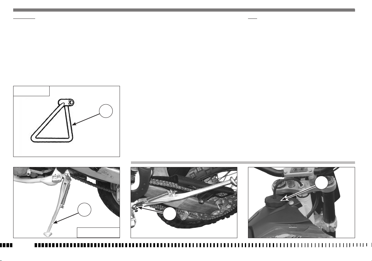
SIDE STAND
A sidestand (1) is supplied with every motorcycle.
WARNING*: The stand is designed to support the weight of the MOTORCYCLE ONLY. Do
not sit on the motorcycle using the stand for
support as this could cause structural failure
to the stand and could cause serious bodily
injury.
Periodically check the side stand (see “Periodical maintenance
card”); check that the springs are not damaged and that the
side stand freely moves. If the side stand is noisy, lubricate the
fastening pivot (A).
FUEL
Recommended fuel: premium grade unleaded fuel. (R.O.N.
98).
Note*: Do not continue operation if the engine pings or knocks. The engine will be damaged and could seize.
WARNING*: If “knocking” or “pinging”
occurs, try a different brand of gasoline or
higher octane grade.
EN - 10
TC
1
1
TE - TXCi
WARNING*: Gasoline is extremely flammable and can be explosive under certain conditions. Always stop the engine and do not
smoke or allow flames or sparks in the area
where the motorcycle is refueled or gasoline
is stored.
WARNING*: Do not overfill the tank. After refueling, make sure the tank cap (2) is closed
securely.
2
A
COLD START
For engine cold starting, the motorcycle features a lever (1) on
the left-hand side of the handlebar. Pull the lever to open the
starting device, vice versa to close it.
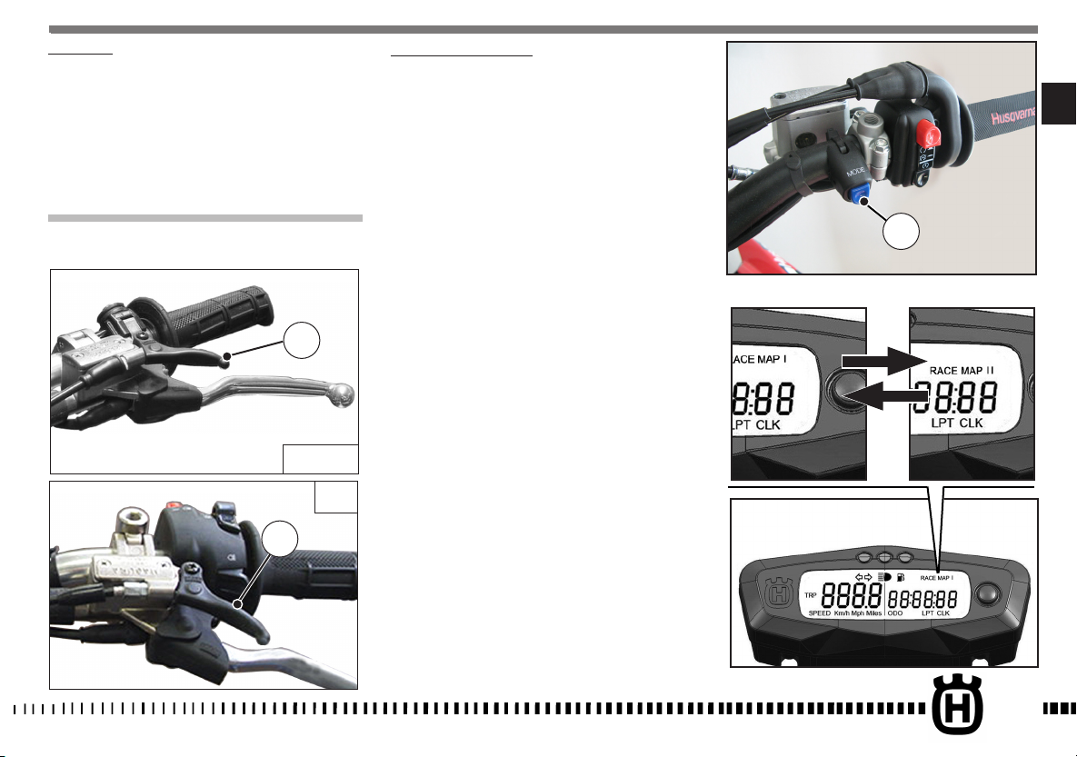
DOUBLE MAP BUTTON (TE)
NOTE:
The button (1) works with full power motorcycles only.
The button (1) allows to modify motorcycle’s performance;
After motorcycle starting, wait for the engine to warm up, then
press the button (1) to toggle through “RACE MAP I” standard
performance to “RACE MAP II” slippery ground performance.
EN
1
TC-TXCi
1
TE
After you switch off the motorcycle, the configuration goes back
to “RACE MAP I” upon the first start-up.
1
EN - 11
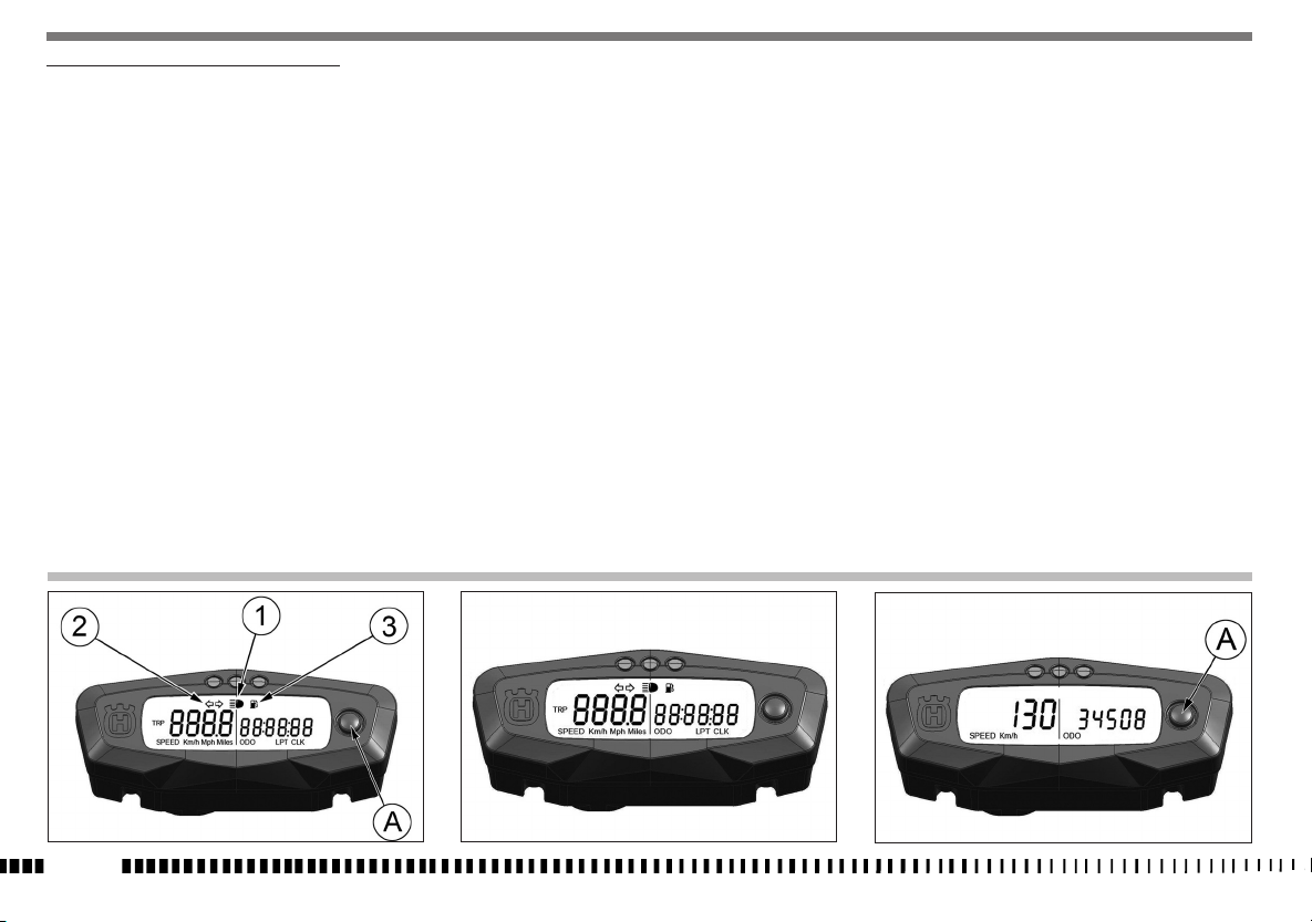
DIGITAL INSTRUMENT, WARNING LIGHTS (TE)
- The instrument functions are the following, as shown below.
1- SPEED (Km/h or mph) / ODO (figure 1)
The motorcycle is equipped with a digital instrument; on the instrument are located 3 warning lights too: high beam, blinkers
and fuel reserve.
1- BLUE warning light “HIGH BEAM”
2- GREEN warning light “BLINKERS”
3- ORANGE warning light “Fuel reserve”
(2,3 l - 2.02 Imp. qt - 2.43 U.S. qt)
Turning the ignition key to the position “IGNITION” the instrument
display illuminates (amber colour).
NOTES
- When linked to the battery,
ment shows the version of the checking SW; after the check,
the instrument shows the last planned function.
- When the motorcycle engine is OFF, the instrument doesn’t
also show its functions.
- To select the instrument functions and to set to zero the functions, use the SCROLL knob (A).
for the first 2 seconds, the instru-
1- SPEED / ODO (figure 1)
2- SPEED / CLOCK (figure 2)
3- SPEED / TRIP (figure 3)
4- SPEED / CHRONO (figure 4)
5- SPEED / RPM (
1- SPEED / ODO (figure 1)
.................
IMPORTANT:: in case of FUEL INJECTION SYSTEM malfunction on the right side of the instrument display will be displayed
the warning message “FAIL”: (see page 14): in this case
contact your local HUSQVARNA Dealer.
engine r.p.m. numerical value
) (figure 5)
- SPEED: motorcycle speed- maximum value: 299 Km/h or 299
mph;
- ODO: odometer- maximum value: 99999 km;
To replace kilometers with miles or miles with kilometers proceed as follows:
1) set to figure 1, stop the engine and push the knob SCROLL
(A);
2) turn the ignition key to the IGNITION position, holding pu-
shed the button SCROLL (A) until the symbol “Km/h” will be
displayed;
3) then the symbols “Km/h” and “Mph Miles” will be displayed
alternatively. Push again the SCROLL (A) button when the
unit you wish to use is displayed.
EN - 12

2- SPEED / CLOCK (figure 2)
- SPEED:
motorcycle speedmaximum value
mph;
clock- Reading from 0:00 to 23:59:59;
- CLOCK:
To reset the clock, push the knob SCROLL (A) for more than 3
seconds in order to increase the hours; release the knob and
then, after 3 seconds, it is possible to increase the minutes;
: 299 Km/h o 299
3- SPEED / TRIP 1 (figure 3)
- SPEED:
motorcycle speedmaximum value
mph
distance- maximum value: 999.9 km (the data will be
- TRIP 1:
lost after battery detachment).
To setup the TRIP, push the SCROLL (A) button holding down
more than 3 seconds
: 299 Km/h o 299
4- SPEED / CHRONO (STP) (figure 4)
- SPEED:
motorcycle speedmaximum value
mph;
miles/kilometers covered time;
- STP 1:
-
Reading from 0:00 to 99:59:59 (the data will be lost after
battery detachment).
To activate the function STP 1, push the knob SCROLL (A) for
more than 3 seconds.
- 1st step: function ON;
- 2nd step: stop to the counters;
- 3rd step: STP 1 zero-setting; TRIP 1 and AVS 1 data zero-setting;
- 4th step: function ON;
- 5th step: stop to the counters;
.............................
and so following
: 299 Km/h o 299
EN
EN - 13

5- SPEED / DIGITAL RPM (figure 5)
- SPEED: velocità- Indicazione max: 299 Km/h o 299 mph
- DIGITAL RPM: MIN. 500, MAX. 14250
The instrument display shows even then informations of the “Neutral” condition and of any possible “Malfunction” of the
INJECTION SYSTEM; this last condition is showed
with absolute priority with respect to any
other information.
NEUTRAL: if the speed is under 20 Km/h (12,5 mph), the “Neutral”
condition the instrument displays the N character before the value
of the speed.
FUEL
WARNING LIGHTS PANEL (TXCi)
The motorcycle is tted with a small warning lights panel
with two warning lights:
1 - Red warning light “POWER”
2 - Yellow warning light “FUEL RESERVE”
EN - 14
MALFUNCTION:
on the right side of the instrument display will be displayed the
warning message “FAIL”
in case of FUEL INJECTION SYSTEM malfunction
.
1
2
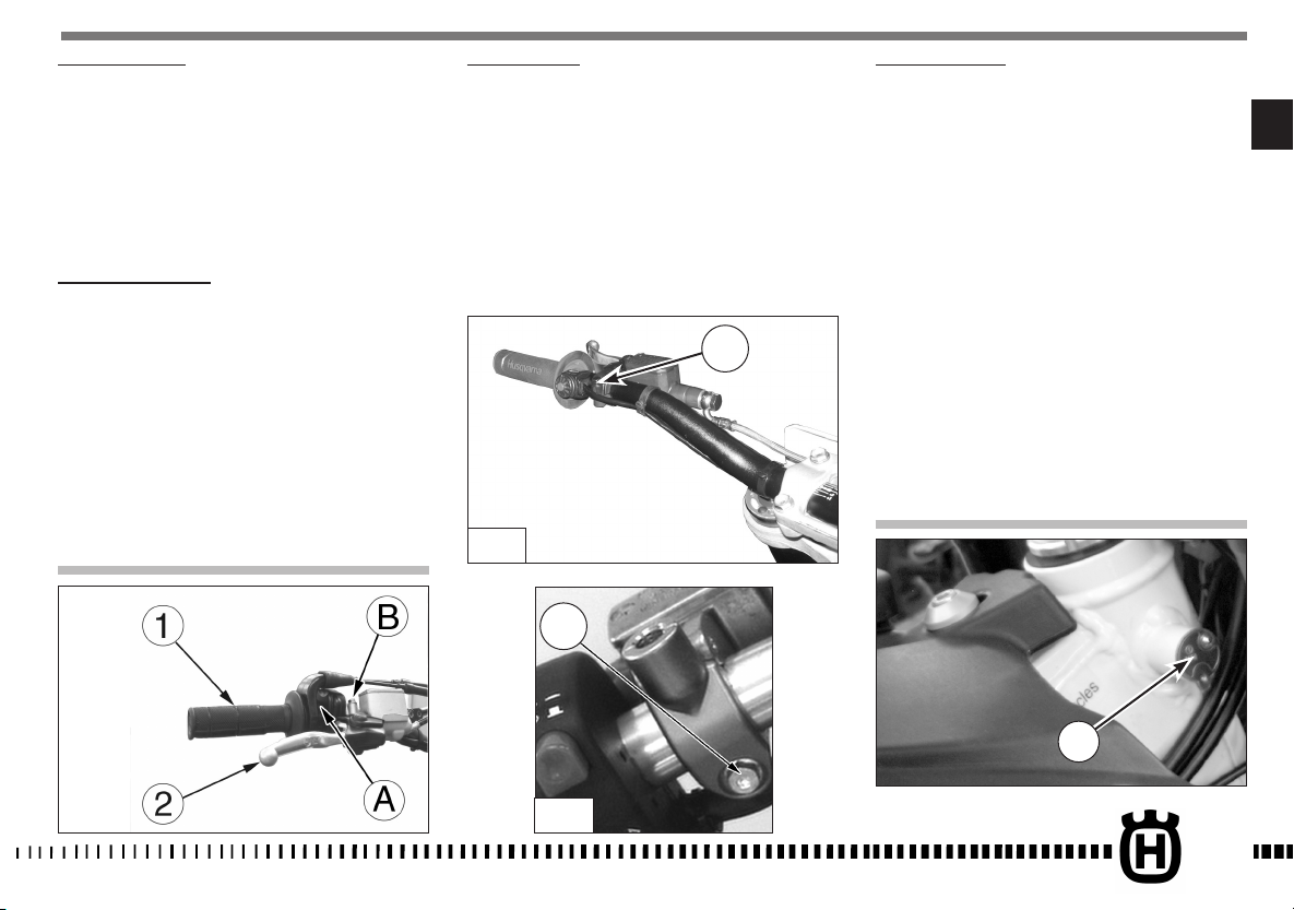
THROTTLE CONTROL
The throttle knob (1), is located on the right hand side of the
handlebar. The position of the throttle control can be adjusted
by loosening the two fastenig screws .
CAUTION
Do not forget to tighten the screws (A) after
the adjustment.
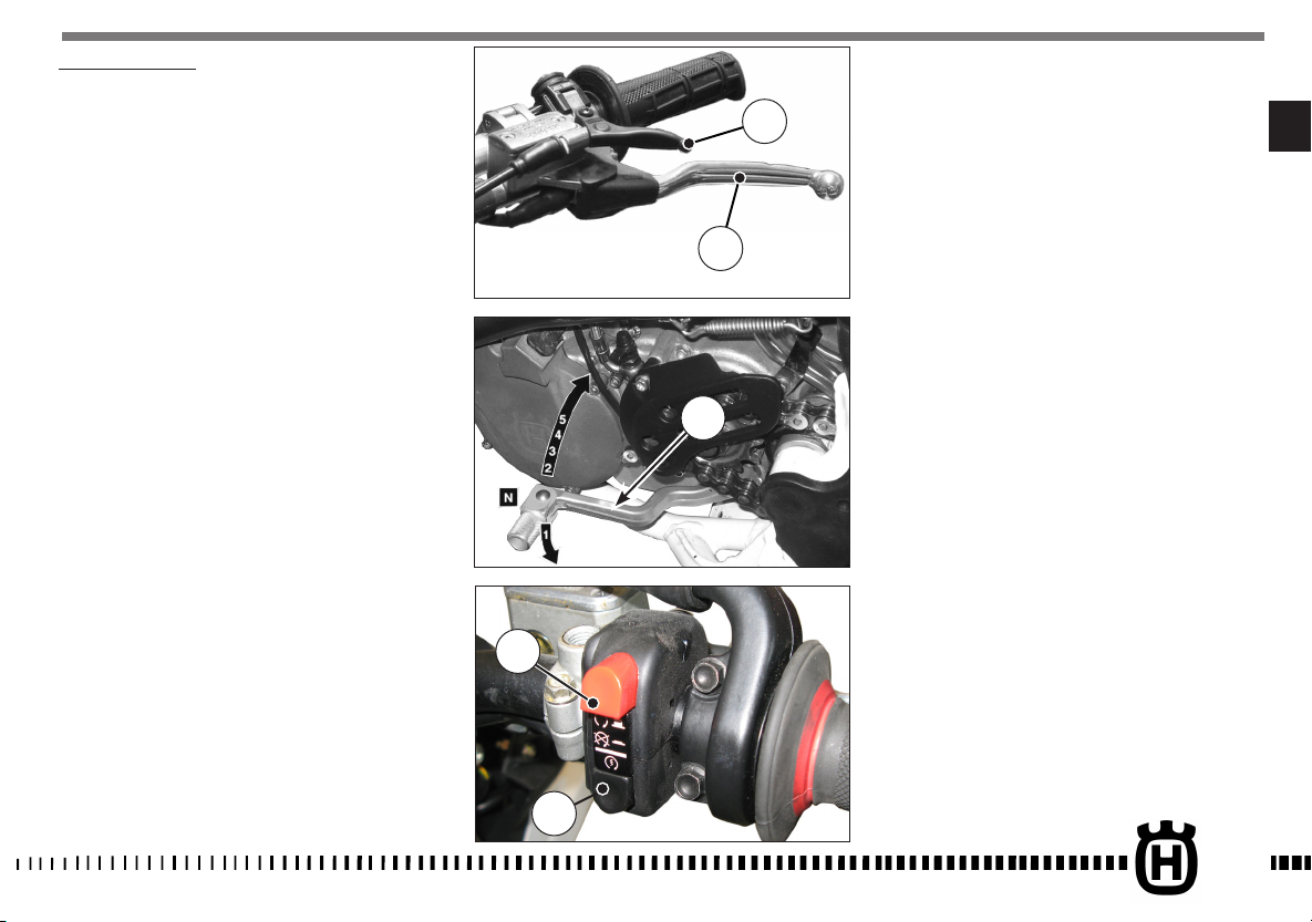
FRONT BRAKE CONTROL
The brake control lever (2) is located on the right hand side of
the handlebar. The position of the throttle control can be adjusted by loosening the two fastenig screws .
CAUTION
Do not forget to tighten the screws (B) after
the adjustment.
CLUTCH CONTROL
The hydraulic clutch control lever is located on the left-hand side
of the handlebar and is protected against dirt with a rubber
guard.
The clutch control position on the handlebar can be adjusted by
loosening the lower fastening screws (A).
CAUTION
Do not forget to tighten the screws after the
adjustment.
A
TC
A
STEERING LOCK (TE)
The motorcycle is equipped with a steering lock (1) on the R.H.
side of the steering head tube.
To lock it, procede as follows:
turn the handlebar leftwards, place the key in lock and turn
counterclockwise. Push the key inwards (if necessary, turn to
and from). Turn the key clockwise and remove it from the lock.
To unlock the steering lock, reverse the above procedure.
EN
TE
1
EN - 15
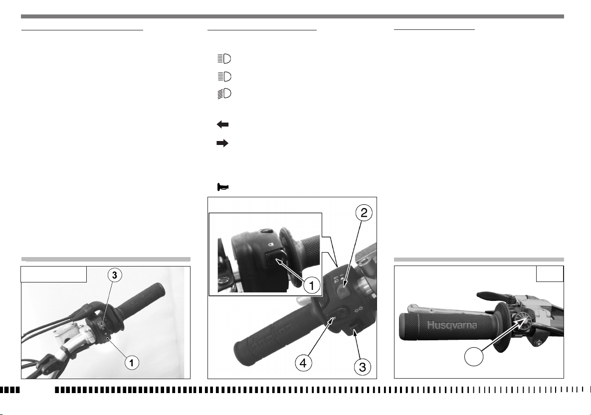
R.H. HANDLEBAR COMMUTATOR (TE-TXCi)
The right commutator has the following controls:
1) Engine start button
3) Engine start - stop switch
L.H. HANDLEBAR COMMUTATOR (TE)
CONTROLS:
High beam flash (self cancelling)
1)
Selection control High beam
2)
Selection control Low beam
Left turn signals (automatic return)
3)
Right turn signals (automatic return)
To deactivate the turn signals, press the control lever after its
returning to center.
Warning horn
4)
ENGINE STOP BUTTON (TC)
On the left side of the handlebar, near the clutch control, is located the engine stop button.
TE - TXCi
EN - 16
TC
1
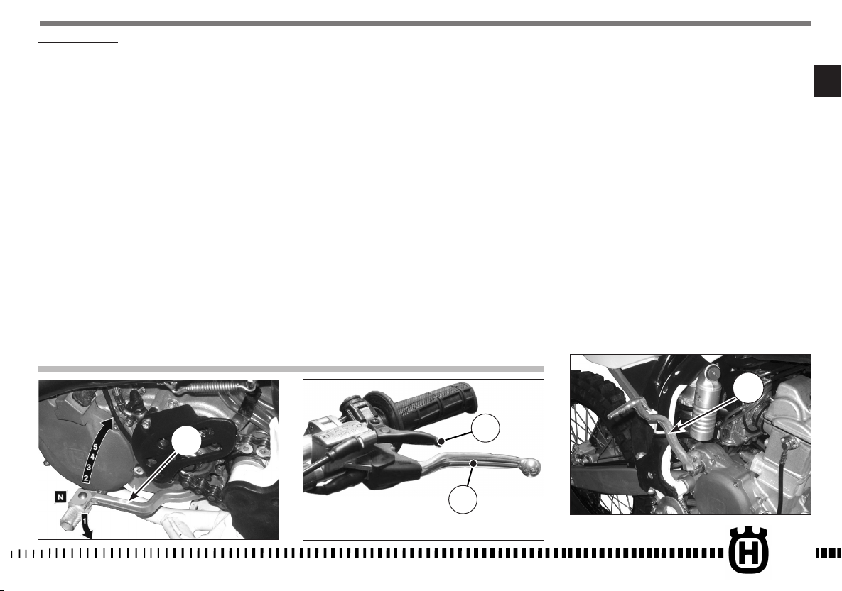
REAR BRAKE CONTROL
The rear brake control (1) is placed on the right-hand side of
the motorcycle.
1
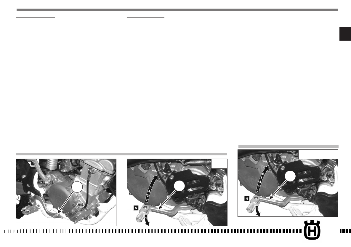
GEAR SHIFT CONTROL
The lever (1) is placed on the left-hand side of the engine. The
operator must release the lever after each gear change to allow
it to return to its central position before another gear
change can be made.
Neutral position (N) is between first (low) and second gears.
First gear is engaged by pushing the lever downwards; all the
other gears are engaged, by pushing the lever upwards.
The position of the gear shift lever on the shaft can be varied
by:
- loosening screw;
- pulling lever out;
- placing lever in new position on the shaft when the operation
is over tighten the screw and then tightening the screw.
CAUTION*: Do not shift gears without disengaging the clutch and closing the throttle. The
engine could be damaged by overspeed and
shock.
N: Neutral
TC
1
WARNING*: Do not downshift when traveling
at a speed that would force the engine to
overrev in the next lower gear, or cause the
rear wheel to lose traction.
N: Neutral
TE - TXCi
1
EN
EN - 17

RIDING
BEFORE EVERY RIDE MAKE FOLLOWING CHECKS
WARNING!
Before each ride, to prevent accidents or failures during ride,
make sure to go through following list.
1. Check all fluids
A. Engine-transmission oil level
B. fuel level
C. coolant level
Make sure all caps are properly adjusted.
WARNING*: Don’t remove radiator cap when
hot!
2. Check all controls
A. Throttle handgrip
B. Clutch lever
Make sure cables are not damaged and turn smoothly.
3. Check brakes
Look for brake fluid leaks and worn hoses. Check for proper
functioning.
4. Check suspensions
Compress fork and rear suspensions. Look for oil leaks and
ensure proper functioning.
5. Check wheels
Check spokes and look for worn bearings.
Check rims and tyres.
Check tyre pressure.
6. Check chain rollers and sprockets
Check wear on chain rollers and sprockets
Ensure chain is correctly adjusted and lubricated.
7. Check air filter and intake system
Check that air filter is clean
Check all rubber connections and clamps.
8. Check exhaust system
Check hook up, look for cracks
Check muffler.
9. Check torque
A. Spark plug
B. General check of torque
10. Check steering action
Check bearing play.
11. Check the electric system (TE).
Start the engine and check that the front and rear lamps, the
stop light, the turn signals the cluster warning lights and the
horn are working correctly.
WARNING*: Failure to perform these checks
every day before you ride may result in serous damage or a severe accident.
.
RUNNING IN
Before using the motorcycle for sporting activities run in the
engine for two hours at least to increase the life and the performance of the engine.
During the first half-hour of driving we advise keeping a low
speed and avoiding sudden accelerations. Never open the throttle fully.
Change the oil and carry out all the necessary maintenance operations. After the first half-hour of driving, lightly increase the
rev number, but never run the engine at full throttle. Never keep
low speeds when the high gears are inserted.
Slowly drive the motorcycle for two hours before using it for
sporting activities.
CHECKS DURING RUNNING
- SPOKE TENSION OF WHEELS;
- TIGHTENING OF WHEELS;
- FORK PIN TIGHTENING;
- CHAIN ADJUSTMENT;
- STEERING BEARING PLAY;
- HANDLEBAR TIGHTENING;
- ENGINE GRIP TO FRAME;
- SUCTION FITTING GRIP;
- HEAD AND CYLINDER NUTS GRIP;
OFTEN CHECK THE BATTERY CHARGE CONDITION
EN - 18
ENGINE START (TC)
While the engine is cold, i.e., after the motorcycle has not been
used for a while or in low ambient temperatures, operate in the
following manner:
1) pull the clutch lever (1);
2) pull the starter lever (2);
3) shift gear pedal (3) to neutral position then release the
clutch control level;
4) COMPLETELY lower the pedal (4) until the engine starts.Bring
the starter lever (2) back to its original position as soon as
the motor can idle. When starting with an already warmed up
engine DO NOT USE the starter. When a cold engine has just
been started, do not increase revs, to ensure an adequate oil
warm-up and circulation.
IMPORTANT NOTE IN CASE OF COLD STARTS AT
LOW TEMPERATURES
It is recommended to briefly warm-up the engine at idle until,
after having disengaged the starter, there is a normal response
from the engine when opening the throttle.
In this way the oil can reach all the surfaces needing lubrication
and the coolant will reach the necessary temperature for correct
engine function. Avoid overheating the engine.
IMPORTANT
Never accelerate the engine after a cold start.
WARNING*: Exhaust contains poisonous carbon monoxide gas. Never run the engine in
a closed garage or in a confined area.
Kick start pedal
WARNING*: This high performance motor-
cycle can some times «kick back» strongly
when you are starting it.
Do not attempt to start this motorcycle unless you are wearing high top heavy sided
riding boots. You could seriously hurt you leg
if the kickstarter kicked back and your foot
slipped.
4
EN
3
2
1
EN - 19

ENGINE START (TE)
With cold engine, as after a prolonged inactivity of the
motorcycle or in presence of a low external temperature,
proceed as follows:
1) set ignition key (1) in IGNITION position (the buzz that you
hear when you turn the key to IGNITION is caused by the
fuel pump which puts the feeding system under pressure);
2) pull the starter lever (2);
3) pull the clutch lever (3);
4) shift gear pedal (4) in neutral position then release the
clutch control lever;
5) Check that the button (5) is in the out position and
press it, followed by the start button (6). Bring the
starter lever (2) back to its original position as
soon as the motor can idle. When starting with an
already warmed up engine DO NOT USE the starter.
When a cold engine has just been started, do not
increase revs, to ensure an adequate oil warm-up
and circulation.
IMPORTANT
NEVER START WITH DISCONNECTED BATTERY.
1
5
6
2
TE
3
IMPORTANT NOTE IN CASE OF COLD STARTS AT
LOW TEMPERATURES
It is recommended to briefly warm-up the engine at idle until,
after having disengaged the starter, there is a normal response
from the engine when opening the throttle.
In this way the oil can reach all the surfaces needing lubrication
and the coolant will reach the necessary temperature for correct
engine function. Avoid overheating the engine.
IMPORTANT
Never accelerate the engine after a cold start.
WARNING*: Exhaust contains poisonous carbon monoxide gas. Never run the engine in
a closed garage or in a confined area.
EN - 20
4
ENGINE START (TXCi)
While the engine is cold, i.e., after the motorcycle has not been
used for a while or in low ambient temperatures, operate in the
following manner:
1) pull the clutch lever (1);
2) pull the starter lever (2);
3) shift gear pedal (3) to neutral position then release the
clutch control level;
4) Check that the button (4) is in the out position and press it,
followed by the start button (5). Bring the starter lever (2)
back to its original position as soon as the motor can idle.
When starting with an already warmed up engine DO NOT
USE the starter. When a cold engine has just been started,
do not increase revs, to ensure an adequate oil warm-up and
circulation.
IMPORTANT NOTE IN CASE OF COLD STARTS AT
2
It is recommended to briefly warm-up the engine at idle until,
after having disengaged the starter, there is a normal response
from the engine when opening the throttle.
In this way the oil can reach all the surfaces needing lubrication
and the coolant will reach the necessary temperature for correct
engine function.Avoid overheating the engine.
LOW TEMPERATURES
EN
1
Never accelerate the engine after a cold start.
WARNING*: Exhaust contains poisonous carbon monoxide gas. Never run the engine in
a closed garage or in a confined area.
IMPORTANT
3
4
5
EN - 21

STOPPING THE MOTORCYCLE AND THE ENGINE
- Close the throttle (1) completely so that the engine will help
slow down the motorcycle.
- For normal braking, gradually apply both front and rear brakes while down shifting (for maximum deceleration, apply the
front and rear brakes firmly).
- When stopped, pull the clutch lever and shift gear lever (2) in
neutral position.
- Press the engine stop RED button (3).
- TE: turn towards left the ignition key.
WARNING*: Independent use of the front or
rear brake may be advantageous under certain conditions. Use caution when using the
front brake, especially on slippery surfaces.
Improper use of the brakes can lead to a serious crash.
2
WARNING*: In the event of stuck throttle or
other malfunction which causes the engine to
run uncontrollably, immediately depress the
engine stop button and hold it down. Control
the motorcycle by normal use of the brakes
and steering while holding the engine stop
button down.
TE
EN - 22
TE - TXCi
3
TC

CHECKING THE OIL LEVEL
Keeping the motorbike level and in a vertical position, check the
oil level through the inspection (1) window on the right crankcase.
Make sure the level is in between the MIN and MAX notches.
To fill up, remove the filler cap (2).
Note*: Have this operation made with warmed-up engine.
WARNING*: Be careful not to touch hot engine oil.
1
a
ENGINE OIL REPLACEMENT AND BAG FILTERS-FILTER
CARTRIDGE CLEANING OR REPLACEMENT
WARNING*: Be careful not to touch hot engine oil.
Drain the oil with WARM ENGINE; proceed as follows:
• remove oil filler cap (2);
• remove the engine lower guard (A);
• place an oil drain pan under the engine block;
• Remove the oil drain cap (3), the mesh filter (4) and drain
the old oil;
A
• Clean the mesh filter with benzine;
• in order to replace the filter cartridge (5), unscrew the three
fastening screws then the filter cartridge cover (6).
Once the oil filters have been cleaned-replaced, fit the parts
back in, in the opposite sequence to the disassembly, and pour
in the prescribed amount of oil, as listed in the LUBRICATION
TABLE on page 8.
EN
3
4
6
5
2
EN - 23

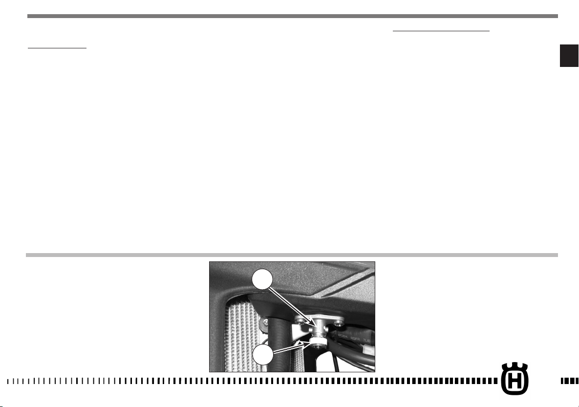
COOLANT LEVEL CHECK
Check level (1) in right-hand radiator when engine is cold (place
the motorcycle so that it is perpendicular to the ground). The coolant should be approximately 10 mm above cells and besides.
The radiator cap (A) is provided of two unlocking positions, the
first being for the previous pressure discharge in the cooling
system.
WARNING
Avoid removing radiator cap when engine
is hot, as coolant may spout out and cause
scalding.
WARNING
TE-TXCi: Remember that the electric fan (B)
can start even with the main switch in the
OFF position; please avoid to operate near
the fins of the fan.
NOTE
Difficulties may arise in eliminating coolant
from varnished surfaces. If this occurs, wash
off with water.
EN - 24
1
A
B

REPLACEMENT OF COOLING FLUID
Place a vessel on the L.H. side of the cylinder, under the Piping (1).
Remove the exhaust pipe (a). Loosen the pipe strap (2) of the piping
(1), take the pipe off the fitting that secures it to the engine, then
SLOWLY open the R.H. radiator cap (3); slope the motorcycle on the
left side to drain the coolant easily in the vessel.
Once over, fit the pipe back in (1) and secure it with the strap (2).
Fit the exhaust pipe back in.
Pour the necessary quantity of coolant in the radiator then warm up
the engine in order to eliminate any possible air bubble.
a
1
Periodically check the connecting hoses (see “Periodical maintenance card”): this will avoid coolant leakages and consequent
engine seizure: If hoses (A) show cracks, swelling or hardenings
due to sheats desiccation, their replacement shall be advisable.
Check the correct tightening of the clamps (B).
3
A: Piping
B: Clamps
EN
A
B
A
B
2
A
EN - 25

THROTTLE CABLE ADJUSTMENT
To check the correct adjustment of the throttle operate as follows:
- remove the upper rubber cap (1);
by moving cable (2) back and forth check for 2 mm. clearance;
-
- should the clearance be incorrect, unblock the counter ringnut (3) and turn the adjusting screw (4) (by unscrewing it,
the clearance is reduced, while by screwing screw (4) it is
increased);
- tighten the counter ring-nut again (3).
WARNING*: Operation with damaged throttle cable could result in an unsafe riding condition.
WARNING*: Exhaust gas contains poisonous
carbon monoxide gas. Never run the engine
in a closed area or in a confined area.
NOTE
In case of throttle control cables (1) and (2) replacement it
is necessary to respect, during reassembly, the measure Á
(10mm/0.4 in.), as shown in the picture. Then reassemble
guard cover (B) using screw (3) and adjust throttle control
cables on handlebar as described at side.
To replace throttle control cables, first remove tha fuel tank.
EN - 26

ADJUSTING THE IDLE
Adjust the carburetor with warm engine and with the throttle
control in closed position. Proceed as follows:
- turn the idle speed adjustment screw (3) on the throttle body,
located on the right side of the vehicle, until the idle speed of
1,950 RPM is reached (turn clockwise to increase the speed
and anti-clockwise to reduce the speed).
3
EN
EN - 27

SPARK PLUG CHECK
Use NGK CR9EB spark plug (2); the gap is 0.027÷0.031 in.
A wider gap may cause difficulties in starting engine and in
overloading coil.
A gap that is too narrow may cause difficulties when accelerating, when idling the engine or when performing at low
speeds.
Clean the dirt away from the base of the spark plug before removing it from the cylinder after removing the cap (1).
It is very useful to examine the state of the spark plug just after it
has been removed from the engine since the deposits on the plug
and the colour of the insulator provide useful indications.
2
Correct heat rating:
The tip of the insulator should be dry and the colour should be
light brown or grey.
High heat rating:
In this case, the insulator tip is dry and covered with dark deposits.
Low heat rating:
In this case, the spark plug is overheated and insulator tip is
vitreous, white or grey in colour.
CAUTION*: Select a spark plug with a colder
or hotter heat range carefully and cautiously. A spark plug with too hot a heat range
may lead to preignition and possible engine
damage. A spark plug with too cold a heat
range may foul as the result of too much carbon buildup.
Before refitting the plug, thoroughly clean the
electrodes and the insulator using a brass-metal
brush.
Apply a little graphite grease to the spark plug
thread; fit and screw the spark plug by hand then
tighten to the torque of 10÷12 Nm- 7.4÷8.9 ft/
lb. Loosen the spark plug then tighten it again
to the torque of 10÷12 Nm- 7.4÷8.9 ft/lb.
Spark plugs which have cracked insulators or
corroded electrodes should be replaced.
EN - 28
1

AIR FILTER CHECK (TC-TXCi)
Turn rear pin (1) counterclockwise, remove the saddle from the
front afstening screw.
TXCi: Take out the battery (A) and place it sideways on the vehicle.
Remove screw (3) and the filter (4). Separate filter (5) from
frame (6).
1
AIR FILTER AND CLEANING
Wash the filter with a specific detergent (“CASTROL FOAM AIR
FILTER CLEANRR” or similar) then dry it fully (wash filter with
gasoline only in case of necessity).
Plunge the filter in special oil for filters (“CASTROL FOAM AIR
FILTER OIL” or similar), then wring it to drain superfluous oil.
CAUTION*: Do not use gasoline or a low flashpoint solvent to clean the element. A fire or
explosion could result.
CAUTION*: Clean the element in a well ventilated area, and do not allow sparks or flames anywhere near the working area.
ASSEMBLY
To ensure tight fit, slightly (C) grease filter edge on side facing
filter housing.
While re-inserting the filter into its housing, make surs that
piece (A) is turned upwards and edge (B) is on the left lower
side of the filter case. Reassemble the parts previously removed
(battery: connect the positive cable first).
CAUTION*: If the element assembly is not
installed correctly, dirt and dust may enter
and the engine resulting in rapid wear of the
piston rings and cylinder.
UPPER SIDE
TC-TXCi
LEFT SIDE
EN
A
4
3
5
6
EN - 29

AIR FILTER CHECK (TE)
Turn rear pin (1) counterclockwise, remove the saddle from the
front afstening screw.
Take out the battery (A) and place it sideways on the vehicle.
Remove screw (3) and the filter (4). Separate filter (5) from
frame (6).
1
AIR FILTER AND CLEANING
Wash the filter with a specific detergent (CASTROL FOAM AIR
FILTER CLEANER or similar) then dry it fully (wash filter with
gasoline only in case of necessity).
Plunge the filter in special oil for filters (CASTROL FOAM AIR
FILTER OIL or similar) then wring it to drain superfluous oil.
CAUTION*: Do not use gasoline or a low flashpoint solvent to clean the element. A fire or
explosion could result.
CAUTION*: Clean the element in a well ventilated area, and do not allow sparks or flames anywhere near the working area.
ASSEMBLY
To ensure tight fit, slightly (C) grease filter edge on side facing
filter housing.
While re-inserting the filter into its housing, make surs that piece
(A) is turned upwards and edge (B) is on the left lower side of
the filter case. Reassemble the parts previously removed (battery: connect the positive cable first).
CAUTION*: If the element assembly is not
installed correctly, dirt and dust may enter
and the engine resulting in rapid wear of the
piston rings and cylinder.
UPPER SIDE
TE
LEFT SIDE
A
EN - 30
4
3
5
6

STEERING WHEEL BALL PLAY ADJUSTMENT
To ensure maximum safety, the steering wheel should always be
regulated so that the handlebars steering the motorcycle rotate
freely without play. To check steering wheel adjustment, place
kick stand or other support under the engine so that the front
wheel is raised from ground.
Place slight pressure on the tips of the handlebars to rotate steering wheel; the handlebars should also rotate without effort.
Stand in front of the motorcycle and grasp the lower end of
the fork rods sliders moving them in the direction of their axis.
Se si avverte gioco occorrerà eseguire la regolazione operando
come segue:
- loosen steering sleeve nut (1).
- Loosen four screws that fix steering head to fork rods (3).
Turn the steering ring nut (2) clockwise of the steering sleeve
proper tool, to adjust play properly.
- Tighten steering sleeve nut (1) to a torque setting of 57,9÷65,1
Lb/ft; (78,4÷88,3 Nm).
- Tighten four screws on the steering head (3) to a torque of
22,5÷26,5 Nm (16.6÷19.5 Lb/ft).
CAUTION*: Do not ride a motorcycle with damaged steering stem bearings. An unsafe
handling condition can result.
LOCK ADJUSTMENT
The lock can be changed, using the adjusting units on the sides
of the steering tube, as follows: loosen the ring nut (1) and turn
the adjusting screw (2) until you have the desired angle, then
tighten the ring nut again (1). Change by the same amount on
both sides.
EN
3
1
1
2
2
EN - 31

ADJUSTMENT OF THE CONTROL LEVER AND CHECK OF THE
FRONT BRAKE FLUID LEVEL
The adjuster (2), located on the control lever, allows adjusting
of the free play (a).
Free play (a) must be at least 3 mm (0.1 in.).
The level of the fluid in pump reservoir must never be below
the minimum value (1), which can be checked from the window
on the rear side of the pump body.
A decrease of the fuel level will let air into the sustem, hence
an extension of the level stroke.
WARNING*: If the brake lever feels mushy
when it is applied, there may be air in
the brake lines or the brake may be
defective. Since it is dangerous to operate
the motorcycle under such conditions, have
the brake checked immediately by an
authorized HUSQVARNA dealer.
CAUTION*: Do not spill brake fluid on to any
painted surface or lenses.
CAUTION*:Do not mix two brands of fluid.
Change the brake fluid in the brake line if
you wish to switch to another fluid brand.
CAUTION*: Brake fluid may cause irritation.
Avoid contact with skin or eyes. In case of
contact, flush thoroughly with water and call
a doctor if your eyes were exposed.
A: to encrease clearance
B: to decrease clearance
EN - 32
1
+
B
-
2
A

REAR BRAKE PEDAL POSITION ADJUSTMENT
The position of the rear foot brake pedal as to the footrest may
be adjusted according to the individual needs. For the adjusting
proceed as follows:
- loosen the screw (1);
- turn the cam (2) in order to adjust the brake pedal idle stroke
(A);
- the operation done, tighten the screw (1).
The adjusting operation carried out, adjust the idle stroke of the
pedal as follows.
REAR BRAKE IDLE STROKE ADJUSTMENT
The rear brake foot pedal should have a (B) 5 mm (0.2 in.) idle
stroke before starting the true braking action.
Should this not happen, operate as follows:
- loosen nut (3);
operate the pump rod (4) to increase or decrease the idle stroke;
-
- tighten nut (3) at the end of the operation.
WARNING
When the idle stroke figures are not met, the
brake pads will be subjected to a fast wear
that may bring to the TOTAL BRAKE INEFFECTIVENESS.
B
EN
EN - 33

CHECKING THE FLUID LEVEL
The level (A) must be set between the pump tank notches.
ADJUSTMENT OF THE HYDRAULIC CLUTCH CONTROL LEVER
Free play (A) must be at least 3 mm (0.1 in.).
The lever position can be adjusted for any driver hand size.
To decrease the lever distance from the handle grip, rotate the
adjuster (B) CLOCKWISE.
To increase the lever distance from the handle grip, rotate the
adjuster (B) COUNTERCLOCKWISE.
B
EN - 34
A

ADJUSTING THE SUSPENSIONS ACCORDING TO PARTICULAR TRACK CONDITIONS
The following information is a useful guide for setting up the
suspensions according to the road conditions.
Always start from the standard calibration before making any
change on the suspensions. Afterwards, increase or decrease the
adjusting clicks one at a time.
HARD GROUND
Fork: softer compression adjustment.
Shock absorber: softer compression adjustment.
The softer adjustment for the two suspensions is also used both
in compression and in extension when driving at top speed, in
order to have better grip of the tires.
SANDY GROUND
Fork: have a harder compression adjustment, or replace the
standard spring with a harder one, and make a softer compression adjustment and a harder extension adjustment at the same
time.
Shock absorber: have a harder compression, and expecially a
harder extension adjustment. Work on the spring preload to
lower the motorcycle rear side.
MUDDY GROUND
Fork: have a harder compression adjustment, or replace the
standard spring with a harder one.
Shock absorber: have a harder compression and extension
adjustments, or replace the standard spring with a harder one.
Work on the spring preload to lift the motorcycle rear side.
We advise replacing the springs of both suspensions to compensate the weight increase due to the piling of the mud.
NOTE:
When the fork results as either too soft or too hard for any
adjustment conditions, check the oil level inside the forkrod.
The level can either be too low or too high. Remember that too
much oil inside the fork will involve a more frequent air drainage. When the suspensions do not react to the changes of calibration, check that the adjusting units are not blocked.
EN
EN - 35

ADJUSTING THE FORK
a) COMPRESSION (TC-TXCi: LOWER REGISTER; TE: UPPER REGI-
STER)
Standard calibration : -9 clicks (TC-TXCi);
Standard calibration : -13 clicks (TE)
To reset to the standadr calibration turn register (A) clockwise
until the position of fully closed is reached then, turn back by
the mentioned clicks. To obtain a smoother braking action, turn
the register anticlockwise. Reverse the operation in order to obtain a harder action.
b) EXTENSION (TC: LOWER REGISTER; TE: UPPER REGISTER)
Standard calibration : -15 clicks (TE);
Standard calibration : -13 clicks (TC-TXCi).
To reset to the standard calibration turn register (C) clockwise to reach the position of fully closed; then, turn back by the
mentioned clicks. To obtain a smoother braking action, turn the
register anticlockwise. Reverse the operation in order to obtain
a harder action.
c) AIR VENT (to carry out after each competition, or monthly).
Set the motorcycle on a central stand and release the fork fully
and loosen the air vent valve (D). Once this operation is over,
tighten the valve.
WARNING: Never force the adjusting screws
beyond the maximum opening and closure
positions.
OIL FORK LEVEL
For the regular fork operation, both legs must be provided with
the necessary oil quantity. Remove the forkrods form the fork to
check the oil level inside the forkrods. Work as follows:
- remove the power rod caps;
- remove springs from the stems letting the oil drop into the
latter;
- bring forks to stroke end;
- check that the level is at distance of 140 mm(5.5 in.) below
the upper limit of rods.
OIL QUANTITY IN EACH FORK LEG
- TC-TXCi: 352 cm
- TE: 646 cm
3
(21.5 cu. in.)
3
(39.4 cu. in.)
a)
EN - 36
D
A
TC
b)
C
TC - TXCi
a)
TE
A

NOTE
Flexibility index for the serial springs:
K=8,8 N/mm (TC-TXCi)
K=89,2 N/mm (TE)
NOTE
Always replace both the spring and the spacers to keep the preload value unchanged.
HANDLEBAR POSITION AND HEIGHT CHANGE
The handlebar position (a) and height (b) can be changed for
better suiting Your driving requirements. To effect these operations, remove the upper clamp (1) and the lower one (2), after
removing the fixing srews (3) and (4).
a) Handlebar position change
Turn the lower clamp (2) 180° to move forward or backward
(10mm- 0.04in.) the handlebar position with respect to the
original setup.
1
A
3
2
b) Handlebar height change
Remove the lower spacer (A) then replace the screw (4) with a
new one of L=65 mm (2.56 in.) height.
Once these operations are completed, tighten the screws (3) to
2,75-3,05 kgm (27-30 Nm; 19.9-22 Lb/fts) and the screws (4)
to 2,0-2,2 kgm (19,6-21,6 Nm; 14.5-15.9 Lb/fts).
1
4
3
2
A
EN
b)
D
C
TE
EN - 37

ADJUSTING THE SHOCK ABSORBER
The rear shock absorber must be adjusted according to the rider
weight and track conditions.
Proceed as follows:
1. With motorcycle on the stand, measure distance (A).
2. Take the normal riding position on the motorcycle with all
your riding apparel.
3. With somebody’s help, take the new distance (A).
B: axis of the panel screw
C: axis of rear wheel pin
4. The difference between these two measurements constitutes
the “SAG” of the motorcycle’s rear end.
Suggested SAG: 4 in. with cold shock absorber. 3.7 in. with
warmed up shock absorber.
5. To get the right SAG according to your weight, adjust the
shock absorber spring preload as described at side.
WARNING*: Never disassemble shock absorber, which contains highly compressed
nitrogen. Contact your Dealer for such major
service. Do not incinerate.
ADJUSTING THE SHOCK ABSORBER SPRING PRELOAD
Proceed as follows:
1. First turn counterclockwise fastening rear pin (1) then remove saddle, screws (2) and R.H. side panel (3).
2
EN - 38
3

2. Clean ringnut (1) and adjusting nut (2) of the spring (3).
3. Either with a hook wrench or an aluminium punch, loosen
the ringnut .
4. Turn the adjusting nut as required.
5. When the adjusting operation is over (according to your
weight and riding style), tighten the ringnut. (Torque for
both ringnuts: 5 Kgm; 49 Nm; 36.2 ft/lb).
6. Reassemble R.H. side panel and saddle.
SHOCK ABSORBER DAMPING ADJUSTMENT
Adjustment of the compression stroke is independent from the
rebound stroke.
A) COMPRESSION - Standard calibration:
1) Low damping speed:
- 15 clicks (± 2 clicks)
(register 4)
B) EXTENSION - Standard calibration:
- 18 clicks (± 2 clicks)
To reset the standard calibration, turn lower register (5) clockwise until reaching fully closed position. Return then back for the
mentioned clicks. In order to obtain a smooth braking
action, turn the register anticlockwise. Reverse the operation
in order to obtain a harder braking action.
EN
WARNING*:Be careful not to touch hot
exhaust pipe while adjusting the shock abosrber.
4
6
1
3
2
2) High damping speed:
- 15 clicks (± 2 clicks)
(register 6)
To reset the standard calibration, turn upper registers (4) and
(6) clockwise until reaching fully closed position.
Return then back for the mentioned clicks. In order to obtain a
smooth braking action, turn the registers anticlockwise.
the operation in order to obtain a harder braking action.
Reverse
5
EN - 39

CHAIN ADJUSTMENT (Fig. A)
Chain should be checked, adjusted and lubricated as per the
Maintenance Chart to ensure security and prevent excessive
wear. If the chains becomes badly worn or is poorly adjusted
(i.e., if it is too loose or too taught), it could escape from sprocket or break.
To adjust the rear chain it is necessary to lower the rear part of
motorcycle so to line up the drive sprocket axle, the rear swing
arm axle and the rear wheel axle as shown on drawing. Than
let turn three times the rear wheel. Now the chain should not
be tight.
FAST ADJUSTMENT (Fig. B)
In the point shown in the figure, fit a bush (a), 35 mm diameter
(or alternatively a shim in the same size) and make sure the
lower branch (C) of the chain is slightly taut.
If it is not, proceed as follows:
- on the right side, with a 27 mm Allen screwdriver, loosen the
locking nut (1) of the wheel pin;
- with a 12 mm screwdriver, loosen the check nuts (2) on both
chain stretchers and work on the screws (3) to achieve the
right tension;
- when the adjustment is over, tighten the check nuts (2) and
the wheel pin nut (1).
When the adjustment is over check the wheel for alignment.
a
Fig. B
C
1
Fig. A
EN - 40
2
3

CHECKING THE WEAR OF CHAIN, PINION AND SPROCKET
Proceed as follows:
- fully stretch the chain with the adjusting screws.
- mark 20 chain links.
- measure the distance “A” between 1st pin center and 21 st
pin center.
STANDARD
LIMIT
WEAR
317,5 mm 323 mm
12,5 in 12,72 in
Check the pinion damages or wear and replace it should the
wear degree be as the one shown in figure.
Remove the wheel and check the wear of the rear sproket teeth.
The below figure shows the outline of teeth in normal and excessive wear. Should the sprocket be badly worn out, replace it
by loosening the six fastening screws to the hub.
WARNING*: Misalignment of the wheel will
result in abnormal wear and may result in
an unsafe riding condition.
Note*: In muddy and wet conditions, mud
sticks to the chain and sprockets resulting
in an overtight chain. The pinion, the chain,
and the rear sprocket wheel wear increases
when running on muddy ground.
Normal
consumption
LUBRICATING THE CHAIN
Lubricate the chain following these instructions.
WARNING * : Never use grease to lubricate
the chain. Grease helps to accumulate dust
and mud, which act as abrasive and hepl to
rapidly wear out the chain, the sprocket, and
the crown.
Disassembling and cleaning
When particularly dirty, remove and clean the chain before
lubrication.
Work as follows:
1 - Set a stand or a block under the engine and see that the rear
wheel is lifted from the ground.
Remove: screws (1), transmission sprocket guard (2), clip
(3), master link (4) and transmission chain (5);
To reassemble, reverse the above procedure.
EN
Excessive
consumption
EN - 41

2 - Check that the chain is neither worn out nor damaged. If the
rollers or the links are damaged, replace the chain by following the instructions given in the Periodical Maintenance
Table.
3 - Check that neither the sprocket nor the crown are damaged.
4 - Wash and clean the chain as described hereunder.
Washing the chain without OR (TC)
Wash using either oil or diesel oil. When using gasoline or tricloroetilene, clean and lubricate the chain to prevent oxidation.
Washing the chain with OR (TE-TXCi)
Wash using oil, diesel oil, or paraffin oil. Never use gasoline,
tricloroetilene, or solvents, as the OR may suffer damages.
Use instead special sprays for chains with OR.
Lubricating the chain without OR (TC)
First dry, then plunge the chain in a bisulphide molybdenum
lubricant, or in high viscosity engine oil. Warm up the oil before
use.
Lubricating the chain with OR (TE-TXCi)
Lubricate all metallic and rubber (OR) elements using a brush,
and use engine oil with SAE 80-90 viscosity for the internal and
external parts.
5 - If the chain has been cut, reassemble using a joint.
6 - Assemble the joint spring (a) by turning the closed side to the
chain direction of rotation as shown in figure below.
NOTE*: Even if all the joints are reusable when in good conditions, for safety purposes we advise using new joints when
reassembling the chain.
7 - Accurately adjust the chain as described on page 40.
4
1
WARNING: The chain oil has NEVER to get in
contact with the tires or the rear brake disk.
Chain tension rollers, chain driving roller,
chain guide, chain runner
Check the wear of the above mentioned elements and replace
them when necessary.
WARNING*: Check the chain guide alignement, and remember that a bent element
can cause a rapid wear of the chain. In this
case, a chain fleeting from the sprocket may
ensue.
a
EN - 42
2
3
1- Chain tension roller
2- Chain driving roller
3- Chain guide
4- Chain slider
a- Joint spring

REMOVING THE FRONT WHEEL
Set a stand or a block under the engine and see that the front
wheel is lifted from the ground. Loosen the bolts (1) holding
the wheel axle (2) to the front fork stanchions.
Hold the head of the wheel axle (2) in place, unscrew the bolt
(3) on the opposite side; draw the wheel axle out.
NOTES
Do not operate the front brake lever when the wheel has been
removed; this causes the caliper piston to move outwards. After
removal, lay down the wheel with brake disc on top.
1
EN
1
3
2
EN - 43

REASSEMBLING THE FRONT WHEEL
Fit the L.H. spacer on the wheel hub.
Fit the wheel between the front fork legs so that the brake disc
is fitted into the caliper.
Fit the wheel axle (2) from the R.H. side, after greasing it and
push it to the stop on the L.H. leg; during this operation, the
wheel should be turned. Tighten the screw (3) on the fork L.H.
side but DO NOT lock it. Now, pump for a while, pushing the
handlebar downwards until you are sure that the fork legs are
perfectly aligned.
Lock: the screws (1) on the R.H. leg (10,4 Nm/ 1,05 Kgm/ 7.7
ft-lb), the screw (3) on the L.H. side (51,45 Nm/ 5,25 Kgm/
38 ft-lb), the screws (1) on the L.H. leg (10,4 Nm/ 1,05 Kgm/
7.7 ft-lb).
1
2
1
NOTE
After reassembly, pump the brake control lever until the pads
are against the brake disc.
EN - 44
3

REMOVING THE REAR WHEEL
Unscrew the nut (1) of the wheel pin (3) and extract it. It is
not necessary to unloose the chain adjusters (2); in this way,
the chain tension will remain unchanged after the reassembly.
Extract the complete rear wheel, by taking care of the spacers
located at the hub sides.
To reassemble, reverse the above procedure remembering to
insert the disc into the caliper.
NOTES
Do not operate the rear brake pedal when the wheel has been
removed; this causes the caliper piston to move outwards.
After removal, lay down the wheel with brake disc on top.
After reassembly, pump the brake control pedal until the pads
are against the brake disc.
EN
1
2
EN - 45

TYRES
Care should be taken to keep the tyres properly inflated. See
"Technical data" chart at the beginning of the manual for correct tyre inflation pressure.
BRAKES
The mayor components are brake master cylinder with its lever
(front) or pedal (rear), brakeline, caliper assembly and disc.
LEGEND
1. Front brake control lever
2. Front brake pump with oil reservoir
3. Front brake hose
4. Front brake caliper
5. Front brake disc
6. Rear brake oil tank
7. Rear brake hose
8. Rear brake caliper
9. Rear brake disc
10. Rear brake pump
11. Rear brake control pedal
EN - 46
2
1
6
10
3
11
8
7
9
5
4

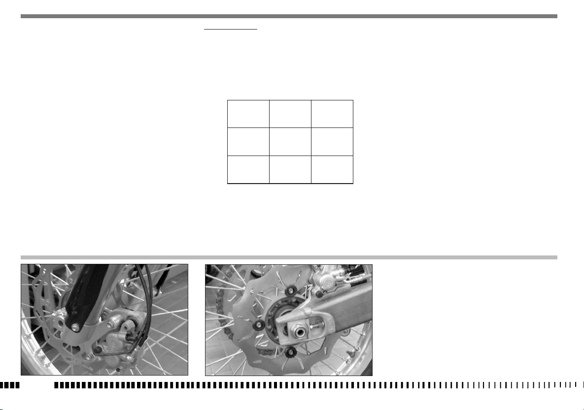
BRAKE PADS REMOVAL
- Remove springs (1).
- Remove pins (2).
- Remove pads.
CAUTION!
Don’t operate the brake lever or pedal while
removing the pads.
FRONT
PADS WEAR
Inspect pads for wear.
Service limit “ A” is: 3,8 mm (0.15 in.).
If service limit is exceeded, always replace the pads in pairs.
PADS CLEANING
Be careful that no disc brake fluid or any oil gets on brake pads
or discs. Clean off any fluid or oil that inadverently gets on the
pads or disc with alcohol.
Replace the pads with new ones if they cannot be cleaned satisfactorily.
PADS INSTALLATION
- Install new brake pads.
- Reassemble the two pins (2) and the springs (1)
FRONT
EN
1
1
2
2
2
2
1
1
REAR
REAR
FRONT REAR
EN - 47
WARNING!
Do not attempt to ride the motorcycle until
the brake lever or pedal are
fully effective. Pump the brake
lever or pedal until the pads are against the
discs.
The brake will not function on the first application of the lever or pedal.
BRAKE DISC WEAR
Measure the thickness of each disc at the point where it has
worn the most. Replace the disc if it has worn past the service
limit.
Disc Thickness
SERVICE
DISC STANDARD LIMIT
Front 3 mm 2,5 mm
(0.12 in.) (0.1 in.)
Rear 4 mm 3,5 mm
(0.16in.) (0.14in.)
EN - 48

DISC CLEANING
Poor braking can also be caused by oil on the disc. Oil or grease
on the disc must be cleaned off with a high flash-point oil free
solvent, such as acetone or lacquer thinner.
EN
EN - 49

EXHAUST MUFFLER
The muffler reduces the noise of the exhaust gases, but it is an
integral part of the exhaust as well. As such, its conditions affect
the motorcycle performance.
When the noise on the exhaust is too high, it means that the
deadening material set on the holed tube inside the muffler
is deteriorated.
BATTERY (TE-TXCi)
The sealed battery does not require any maintenance work.
When electrolyte leaks, or other failures to the electrical system
are detected, apply to the HUSQVARNA Dealer.
If the vehicle remains unused for long periods, it is recommended to remove battery from electrical system and store it
in a dry place.
- After an intensive use of the battery, it’s advisable a standard
low charge (12V-7Ah battery: 0.7A for 8 hours).
-- Rapid recharging is advised only in situations of extreme necessity since the life of lead elements is drastically reduced
(7A for 0.5 hours with 12V-7Ah batteries).
BATTERY CHARGER
To gain access to the battery (2):
- first turn counterclockwise fastening rear pin (1) then remove
the saddle;
- first remove the BLACK or BLUE negative cable, then the RED
positive cable (when reassembling, first connect the RED positive cable, then the BLACK or BLUE negative cable);
- remove the battery (3) from its housing.
Check, using a voltmeter, that battery voltage is not less than
12,5 V.
If not, the battery needs to be charged.
Using a battery charter with a constant voltage, first connect
the RED positive cable to the battery’s positive terminal then
the BLACK or BLUE negative cable to the battery’s negative ter-
minal.
Apply to the constant voltage of 14,4 V a current of “x” Ampere
as results in the belowe diagram (depending on the amount of
carging required).
EN - 50
2

The voltage reaches a constant value only after a few hours,
therefore it is suggested NOT to measure it immediately after
having charged or discharged the battery.
Always check the charge level bifore reinstalling it on the vehicle.
The battery should be kept clean and the terminals coated with
grease.
WARNING*: The battery contains sulfuric
acid. Avoid contact with skin, eyes or clothing. Antidote: EXTERNAL - Flush with water.
INTERNAl - Drink large quantities of water or
milk. After milk take magnesia, beaten eggs
or vegetable oil. Call physician immediately.
Eyes: Flush with water for no less than 15
minutes and get prompt medical attention.
INDICATIVE VALUES RELATIVE TO THE CHARGING TIME DEPENDING ON BATTERY STATUS
VOLTAGE * (V) % CHARGE CHARGE TIME (THE “AMPERE” RATED CURRENT TO APPLY IS: 0,1x BATTERY RATED
CAPACITY)
WARNING*: In case on unused of the battery
it has to be , in any case, re-charged with
slow cycle (0,7A for 8 hours for batteries
12V-7Ah) at least every 3 weeks.
WARNING*: Batteries produce explosive gas,
ventilate when charging or using in enclosed
space. When using a battery charger before
turning on the charger. This procedure prevents sparks at the battery terminals which
could ignite any battery gases.
EN
> 12,7 100 _
~12,5 75 4h
~12,2 50 7h
~12,0 25 11h
~11,8 0 14h
EN - 51

HEADLAMP BULBS REPLACEMENT (TE)
To gain access to the healamp bulbs, proceede as follows:
- remove the upper fastening screw of the the headlamp carrier to
the instrument panuel support (A);
- push forward the headlamp carrier (B) and pull it towards the
high (C) in order to uncouple from the two lower supports.
- remove the headlamp carrier;
C
A
- remove the two filaments bulb (7) connector (2) and the boot
(3);
- remove the screw (6);
- release the bulb holding spring (4) and then the bulb itself.
To replace the parking light bulb (5) extract it from the inside
cover.
After replacement, reverse operations for reassembly.
3
5
4
TAIL LIGHT
The back light is a LED light.
EN - 52
B
5
6
4
7
3
2

REPLACING THE NUMBER PLATE LAMP (TE)
- loosen screw (1) and remove the number plate bulb (2) from
the mudguard;
- take bulb holder (3) and bulb (4) out of the support;
- pull the bulb (4) to detach it from bulb holder.
Once the bulb has been replaced, reverse the above procedure
to reassemble.
2
1
3
ADJUSTMENT OF HEADLIGHT (TE)
When checking the proper orienting of headlight, inflate tires
at right pressure, sat a person on the saddle and place the motorcycle perpendicular with its longitudinal axis 10 meter (33
ft) from a wall or screen. Then trace an horizontal line equal to
the height of headlight center and a vertical one in line with its
longitudinal axis.
If possibile, execute this operation in a shadowy place.
When the low beam is on, the upper boundary limit between
dark and lit zone should be 9/10 th of headlight center from
groud.
Adjust the preadlamp aiming by turning screw (1) to lower or
lift the high beam.
EN
1
4
EN - 53

APPENDIX
AFTER-RACE CHECK POINTS
After racing, first clean the motorcycle and then inspect the
entire motorcycle, with special attention to the items listed in
«MAINTENANCE» table (Appendix A), such as the air cleaner,
carburetor, brakes, etc.
Carry out general lubrication, and make adjustment as necessary.
- Lubricate the drive chain and all the cables.
- Spray oil on all unpainted metal surfaces to prevent rusting.
Avoid getting oil on rubber parts or in the brakes.
- Set the motorcycle on a box or stand so that both wheels are
raised off the ground. (If this cannot be done, put boards under the front and rear wheels to keep dampness away from
the tire rubber).
- Tie a plastic bag over the exhaust pipe to prevent moisture
from entering.
- Put a cover over the motorcycle to keep dust and dirt from
collecting on it.
To put the motorcycle back into the use after storage.
- Make sure the spark plug is tight.
- Fill the fuel tank.
- Run the engine to warm the oil then drain the oil.
- Put in fresh transmission oil.
- Check all the points listed under the inspection and Adjustment Section (Appendix A).
- Lubricate the points (listed in the Lubrication Section (Appendix A).
CLEANING
IMPORTANT RECOMMENDATION
Premised that, before the motorcycle washing, it is necessary to
protect opportunely from the water the following parts:
a) Rear opening of the muffler;
b) Clutch and brake levers, hand grips, handlebar commutators;
c) Air cleaner intake;
d) Fork head, wheel bearings;
e) Rear suspension links,
It is necessary ABSOLUTELY TO AVOID THAT
HIGH PRESSURE JETS OF WATER OR AIR come
to contact with THE ELECTRICAL PARTS AND
FUEL INJECTION PARTS, especially the electronic control unit and the sensors group
M.A.Q.S. and the dashboard.
After washing
- Remove the plastic bags, and clean the air cleaner intake.
- Lubricate the points listed in the Maintenance Table (Appendix A).
- Briefly warm-up the engine
- Test the brakes before riding the motorcycle.
WARNING*: Never wax or lubricate the
brake disc. Loss of braking and an accident
could result. Clean the disc with an oilless
solvent such ans acetone. Observe the solvent warnings.
EN - 54

Olio motore Controllo livello
Olio miscela benzina Controllo livello
Liquido di raffreddamento Controllo / Ripristino livello
Impianto raffreddamento Controllo perdite
Elettroventole Controllo funzionamento
Candele Controllo / Sostituzione
Corpo farfallato / Carburatore Controllo e Regolazione
Fluido freni e frizione Controllo livello
Freni / Frizione Controllo funzionalità
Freni / Frizione Controllo circuito
Comando acceleratore Controllo funzionalità
Comando acceleratore Verifica/regolazione gioco
Comando starter Controllo funzionalità
Trasmissioni e com. fless. Controllo / Regolazione
Catena di trasmissione Controllo / Regolazione
Pneumatici Controllo pressione
Cavalletto laterale Controllo funzionalità
Interrutt. cavall. laterale Controllo funzionalità
Impianto elettrico Controllo funzionalità
Strumentazione Controllo funzionalità
Luci / segnali visivi Controllo funzionalità
Avvisatore acustico Controllo funzionalità
Fanale anteriore Controllo funzionalità
Interruttore accensione Controllo funzionalità
Serrature Controllo funzionalità
Serraggio viti e dadi Controllo / serraggio
Fascette stringitubo Controllo / serraggio
Lubrificazione generale
Collaudo generale
Engine oil Check level
Two-stroke mix oil level Check level
Coolant Check / Restore level
Cooling system Check for leakage
Electric fans Check operation
Spark plugs Check / Replace
Throttle body / Carburettor Check and adjust
Brakes / Clutch fluid Check level
Brakes / Clutch Check operation
Brakes / Clutch Check lines for leakage
Throttle control Check operation
Throttle control Check / Adjust play
Choke control Check operation
Flexible controls and transm. Check / Adjust
Drive chain Check / Adjust
Tyres Check pressure
Side stand Check operation
Side stand switch Check operation
Electrical equipment Check operation
Instrument panel Check operation
Lights / Visual signals Check operation
Horn Check operation
Headlight Check operation
Ignition switch Check operation
Locks Check operation
Screws and nuts Check / Tighten
Hose clamps Check / Tighten
General lubrication
General test
: presenti solo sui motocicli con motore a 2 tempi
: presente solo su alcuni modelli
: only for motorcycles with 2 stroke engine
: only for some models
OPERAZIONI DI PRECONSEGNA
Descrizione Operazione Preconsegna
Descrizione Operazione Preconsegna
PRE -DELIVERY INSPECTION
Description Operation Pre-delivery
Description Operation Pre-delivery
EN
EN - 55

ALPHABETICAL INDEX
Page
A
Adjusting the fork ..........................................................................36
Adjusting the idle ..........................................................................27
Adjusting the shock absorber ..........................................................38
Adjusting the shock absorber spring preload ...................................38
Adjusting the suspensions according to particular track conditions ...35
Adjustment of headlight (TE) ..........................................................53
Adjustment of the control lever and check of the front brake fluid
level .............................................................................................32
Adjustment of the hydraulic clutch control lever .............................34
After-race check points ...................................................................54
Air filter and cleaning.....................................................................29
Air filter check (TC-TXCi) .................................................................29
Air filter check (TE).........................................................................30
Assembly .......................................................................................29
Assembly .......................................................................................30
B
Battery charger ..............................................................................50
Battery ...........................................................................................50
Brake disc wear ..............................................................................48
Brake pads removal .......................................................................47
Brakes ...........................................................................................46
C
Chain adjustment ...........................................................................40
Checking the fluid level ..................................................................34
Checking the oil level .....................................................................23
Checking the wear of chain, pinion and sprocket ............................41
Cleaning .......................................................................................54
Clutch control .................................................................................15
Controlli durante il rodaggio ..........................................................18
Coolant level check .........................................................................24
D
Digital instrument, warning lights ..................................................12
Disc cleaning ..................................................................................49
Double map button ........................................................................11
E
Engine oil replacement and bag filters-filter cartridge cleaning or
replacement ...................................................................................23
Engine start (TC) ............................................................................19
Engine start (TE) ............................................................................20
Engine start (TXCi) .........................................................................21
Engine stop button .........................................................................16
Exhaust muffler .............................................................................50
F
Fast adjustment .............................................................................40
Front brake control.........................................................................15
Fuel ...............................................................................................10
Fuel cock ..........................................................................................9
Fuel injection engine ........................................................................9
G
Gear shift control ...........................................................................17
H
Handlebar position and height change ...........................................37
Headlamp bulbs replacement .........................................................52
L
L.H. Handlebar commutator............................................................16
Lock adjustment .............................................................................31
Lubricating the chain ......................................................................41
O
Oil fork level ..................................................................................36
P
Pads cleaning .................................................................................47
Pads installation ............................................................................47
Pads wear ......................................................................................47
R
Rear brake control .........................................................................17
Rear brake idle stroke adjustment ..................................................33
Rear brake pedal position adjustment ...........................................33
Reassembling the front wheel ........................................................44
Removing the front wheel ..............................................................43
Removing the rear wheel ...............................................................45
Replacement of cooling fluid ..........................................................25
Replacing the number plate lamp ...................................................53
R.H. Handlebar commutator ...........................................................16
Running in .....................................................................................18
S
Shock absorber damping adjustment ..............................................39
Side stand ......................................................................................10
Spark plug check ............................................................................28
Steering lock ..................................................................................15
Steering wheel ball play adjustment ...............................................31
Stopping the motorcycle and the engine .........................................22
T
Tail light ........................................................................................52
Throttle cable adjustment ...............................................................26
Throttle control ...............................................................................15
Tyres ..............................................................................................46
W
Warning lights panel ......................................................................14
EN - 56

APPENDICE A
APPENDIX A
APPENDICE A
ANHANG A
APÉNDICE A
A
1

TC-TE-TXC 250
MOTOCICLO DA COMPETIZIONE, PER USO AGONISTICO: A PIENA POTENZA
COMPETITION MOTORCYCLE, RACING USE: with FULL POWER ENGINE
MOTOCYCLE DE COMPÉTITION, POUR USAGE SPORTIF: AVEC LA PLEINE PUISSANCE
SCHEMA DI MANUTENZIONE PERIODICA (DA EFFETTUARE PRESSO IL CONCESSIONARIO HUSQVARNA-
PERIODIC MAINTENANCE SCHEDULE (SEE YOUR HUSQVARNA DEALER FOR THESE SERVICES)-
ESQUEME ENTRETIEN PERIODIQUE (EFFECTUER PAR LE VOTRE CONCESSIONAIRE HUSQVARNA)
TAGLIANDO
COUPON
COUPON
TAGLIANDO
COUPON
COUPON
TAGLIANDO
COUPON
COUPON
TAGLIANDO
COUPON
COUPON
TAGLIANDO
COUPON
COUPON
PARTICOLARE- ITEM- PARTICULAIRE
DOPO LE PRIME 3
ORE-AFTER FIRST
3 hours-APRÈS LES
PREMIER 3 heures
OGN
EVERY
TOUS LES
OGNI
EVERY
TOUS LES
OGNI
EVERY
TOUS LES
OGNI
EVERY
TOUS LES
OGNI
EVERY
TOUS LES
SOSTITUIRE SE
NECESSARIO
REPLACE IF
NECESSARY
REMPLACER SI
NÉCESSAIRE
VEDERE PAGINA
SEE PAGE
VOIR PAGE
4h MX/8h EN 8h Mx/16h EN 16h MX/32h EN 32h MX/64h EN 40h MX/80h EN
VALVOLE- VALVE- SOUPAPES
C (GIOCO
CLEARANCE-
JEAU) (•)
C (GIOCO-
CLEARANCE-
JEAU) (•)
S (#)
#
MOLLE VALVOLE- VALVE SPRING- RESSORTS SOUPAPES Cx#
SCODELLINI, SEMICONI VALVOLE- V ALVE CUP, VA LVE HALF CONE- CUVETTES, DEMI-CÔNE SOUPAPES Cx#
ALBERO A CAMME- CAMSHAFT- ARBRE DISTRIBUTION C#
CATENA DISTRIBUZIONE- VALVE TIMING CHAIN- CHAINE DISTRIBUTION CS #
PATTINO CATENA DISTRIBUZIONE- VALVE TIMING CHAIN SLIDER- GLISSIÈRE CHAINE DISTRIBUTION
#
INGRANAGGIO CONDOTTO DISTRIBUZIONE- VALVE TIMING DRIVEN GEAR- ENGRENAGE CONDIUT DISTRIBUTION Cx#
INGRANAGGIO CONDUTTORE DISTRIBUZIONE- VALVE TIMING DRIVING GEAR- ENGRENAGE CONDUCTEUR
DISTRIBUTION
Cx#
TENDITORE CATENA DISTRIBUZIONE- VALVE TIMING CHAIN TENSIONER- TENDEUR CHAINE DISTRIBUTION C#
RACCORDO DI ASPIRAZIONE- INTAKE MANIFOLD- RACCORD ADMISSION CS #
CILINDRO COMPLETO- CYLINDER ASSY.- CYLINDRE COMPL. Cx#
PISTONE COMPLETO- PISTON ASSY.- PISTON COMPL. CS #
BIELLA MOTORE COMPLETA- CONNECTING ROD ASSY.- BIELLE COMPL. S#
CUSCINETTI BASAMENTO- CRANKCASE BEARINGS- ROULEMENTS CARTERS S#
OLIO MOTORE- ENGINE OIL - HUILE MOTEUR
SS 23
POMPA OLIO - OIL PUMP - POMPE HUILE C#
FILTRO OLIO/FILTRO A RETE- OIL FILT ER CARTRIDGE/ NET OIL FILTER- FILTRE HUILE/ FILTRE A RESEAU
S, PS, P 23
TUBAZIONE LUBRIFICAZIONE POMPA OLIO/BASAMENTO- OIL PUMP/CRANKCASE HOSE- TUYAU POMPE HUILE/
CARTERS
C#
COPPIA INGRANAGGI TRASM. PRIMARIA- SET OF MATCHED PRIMARY ENGRENAGES TRANSM. PRIMARIE- C#
MOZZO FRIZIONE- CLUTCH HUB- MOYEAU PORTE-DISQUE EMBRAYAGE Cx#
DISCHI FRIZIONE- CLUTCH DISCS- DISQUES EMBRAYAGE CSx#
PIATTO SPINGIDISCHI FRIZIONE- CLUTCH DISCS PRESSURE PLATE- POUSSE DISQUES EMBRAYAGE C#
MOLLE FRIZIONE- CLUTCH SPRING- RESSORT EMBRAYAGE Cx#
CAMPANA FRIZIONE- CLUTCH DISCS HOUSING- CAGE EMBRAYAGE C#
ASTINA DISINNESTO FRIZIONE- CLUTCH DISENGAGEMENT ROD- BILLE COILESSAU DÉBRAYAGE EMBRAYAGE C#
PIGNONE USCITA CAMBIO- DRIVE SPROCKET- PIGNON CHAÎNE TRANSMISSION CS x 42
INGRANAGGI AVVIAMENTO- STARTING GEARS - ENGRENAGE DÉMARRAGE Cx#
C/S
S
S
C
C
BICCHIERINI - CUP - COUVETTE
Cx#
TC-TE-TXCi 250 / TE 310
A2

TC-TE-TXC 250
KONKURRENZ-MOTORRAD, das Machen EINEN WETTKAMPF MIT
von der VERWENDUNG: mit VOLLEM MACHT-MOTOR
MOTOCICLO DE COMPETICIÓN, PARA USO AGONÍSTICO: A LLENA POTENCIA
WARTUNGSTABELLE (FÜR DIESE KONTROLLEN WENDEN SIE SICH AN IHREN
VERTRAGSHÄNDLER HUSQVARNA)- ESQUEMA DE MANTENIMIENTO PERIODICO (PARA
EFECTUAR ESTAS OPERACIONES DIRÍJASE A SU CONCESIONARIO HUSQVARNA)
COUPON-CUPÓN
COUPON-
CUPÓN
COUPON-
CUPÓN
COUPON-CUPÓN
COUPON-
CUPÓN
TEILE- PARTICULAR
NACH DER ERSTEN 3
STUNDEN-DESPUÉS DE
LAS PRIMERAS 3 horas
ALLE-CADA ALLE-CADA ALLE-CADA ALLE-CADA ALLE-CADA
WECHSELN
WENN NÖTIG-
SUBSTITUÍR SI
NECESARIO
SIEHE SEITE-
VER PAGINA
4h MX/8h EN 8h Mx/16h EN 16h MX/32h EN 32h MX/64h EN 40h MX/80h EN
VENTIL- VÁLVULAS
C (BETRIEBSSPIEL-
JUEGO) (•)
C (BETRIEBSSPIEL
-
JUEGO) (•)
S (#)
#
VENTILFEDER- RESORTES VÁLVULAS Cx#
TELLER, HALB KEGEL- CUBETAS, SEMI-CONOS VÁLVULAS
Cx#
NOCKENWELLE- EJE DISTRIBUCIÓN
C#
VENTILSTEUERUNGKETTE- CADENA DISTRIBUCIÓN CS #
VENTILSTEUERUNGKETTEGLEITBAHN- PLATO CADENA DISTRIBUCIÓN #
VENTILSTEUERUNGZAHNRAD- ENGRENAJE CONDUCTO DISTRIBUCIÓN Cx#
VENTILSTEUERUNGANTRIEBSRAD- ENGRENAJE CONDUCTOR DISTRIBUCIÓN Cx#
VENTILSTEUERUNGKETTESPANNER- TENSOR CADENA DISTRIBUCIÓN C#
ANSCHLUSS- EMPALME DE ASPIRACIÓN CS #
ZYLINDER KPL.- CILINDRO COMPLETO Cx#
KOLBEN KPL.- PISTÓN COMPLETO CS #
PLEUELSTANGE KPL.- BIELA MOTOR COMPLETA S#
GEHAUSELAGER- COJÍNETE DE CARTER S#
MOTORÖL- ACEITE MOTOR SS 23
ÖLPUMPE- BOMBA ACEITE C#
WECHSELFILTER/ SIEBFILTER- FILTRO ACEITE MOTOR/ FILTRO DE RED S, PS, P 23
SCHMIERUNGROHR FÜR ÖLPUMPE/GEHAUSE- TUBO LUBRICACIÓN BOMBA ACEITE/BANCADA C#
STIRNRADERPAAR- GRUPO ENGREN. TRANSM. PRIMARIA C#
KUPPLUNGSCHEIBENHALTERNABE- CUBO PORTA DISCOS EMBRAGUE Cx#
KUPPLUNGSCHEIBE- DISCOS EMBRAGUE CSx#
KUPPLUNGDRUCKPLATTE- PLATO EMPUJA DISCOS EMBRAGUE C#
KUPPLUNGFEDER- RESORTE EMBRAGUE Cx#
KUPPLUNGKORB- CAMPANA EMBRAGUE C#
KUPPLUNGSTEUERSTANGE- VARILLA DESEMBRAGUE C#
RITZEL- PIÑÓN CADENA CS x 42
ANLASSERANTRIEBSRAD- ENGRENAJE DE ARRANQUE Cx#
ANLASSERHEBEL- PALANCA ARRANQUE L#
GANGSCHALTUNGHEBEL- PEDAL MANDO CAMBIO Cx 17
S
S
C
C/S
C
TELLER - CUBETA
Cx
#
TC-TE-TXCi 250 / TE 310
A
A3

TC-TE-TXC 250
MOTOCICLO DA COMPETIZIONE, PER USO AGONISTICO: A PIENA POTENZA
COMPETITION MOTORCYCLE, RACING USE: with FULL POWER ENGINE
MOTOCYCLE DE COMPÉTITION, POUR USAGE SPORTIF: AVEC LA PLEINE PUISSANCE
SCHEMA DI MANUTENZIONE PERIODICA (DA EFFETTUARE PRESSO IL CONCESSIONARIO HUSQVARNA-
PERIODIC MAINTENANCE SCHEDULE (SEE YOUR HUSQVARNA DEALER FOR THESE SERVICES)-
ESQUEME ENTRETIEN PERIODIQUE (EFFECTUER PAR LE VOTRE CONCESSIONAIRE HUSQVARNA)
TAGLIANDO
COUPON
COUPON
TAGLIANDO
COUPON
COUPON
TAGLIANDO
COUPON
COUPON
TAGLIANDO
COUPON
COUPON
TAGLIANDO
COUPON
COUPON
PARTICOLARE- ITEM- PARTICULAIRE
DOPO LE PRIME 3
ORE-AFTER FIRST
3 hours-APRÈS LES
PREMIER 3 heures
OGN
EVERY
TOUS LES
OGNI
EVERY
TOUS LES
OGNI
EVERY
TOUS LES
OGNI
EVERY
TOUS LES
OGNI
EVERY
TOUS LES
SOSTITUIRE SE
NECESSARIO
REPLACE IF
NECESSARY
REMPLACER SI
NÉCESSAIRE
VEDERE PAGINA
SEE PAGE
VOIR PAGE
4h MX/8h EN 8h Mx/16h EN 16h MX/32h EN 32h MX/64h EN 40h MX/80h EN
PEDALE AVVIAMENTO- STARTING PEDAL- LEVIER DÉMARRAGE L#
PEDALE COMANDO CAMBIO - CLEAR CONTROL PEDAL - LEVIER COM. DE VITESSE C 17
CANDELA ACCENSIONE - SPARK PLUG - BOUGIE D’ALLUMAGE
PS 28
PIPETTA CANDELA - SPARK PLUG GAP - PIPETTE BOUGIE D’ALLUMAGE C#
CARBURATORE- CARBURETOR- CARBURATEUR (TC) PR#
VALVOLA GAS CARBURATORE- CARBURETOR THROTTLE VALVE - SOUPAPE DE GAZ DU CARBURATEUR (TC) C#
FILTRO ARIA- AIR FILTER- FILTRE À AIR P, L 29
RADIATORI- RADIATORS- RADIATEURS C #
TUBAZIONI ACQUA E FASCETTE- COOLANT HOSES AND CLAMPS- TUYAU EAU ET COLLIER C 25
TUBAZIONE RADIATORI/POMPA ACQUA- RADIATORS HOSE/WATER PUMP- TUYAU RADIATEURS/POMPE EAUC 25
FLUIDO REFRIGERANTE- COOLANT- RÉFRIGÉRANT C x 24
PEDANE APPOGGIAPIEDI, PERNI, MOLLE- FOOTRESTS, FOOTREST PINS AND SPRINGS- REPOSE PIEDS, PIVOTS,
RESSORTS
Cx#
PERNI FISS. TELAIETTO, PERNI FISS. MOTORE- SADDLE FRAME FASTENING BOLTS, ENGINE FASTENING BOLTSPIVOTS DE FIXATION CADRE SIEGE, PIVOTS DE FIXATION MOTEUR
CC #
CAVALLETTO LATERALE -SIDE STAND - BEGUILLE LATERALE C 10
RULLO GUIDACATENA, CUSCINETTO- CHAIN GUIDE ROLLER, BEARINGS- AIGUILLE GUIDE-CHAINE, ROULEMENT C 43
TESTA DI STERZO, BASE DI STERZO CON PERNO- STEERING HEAD, STEERING CROWN WITH PIN- TÊTE
DIRECTION, SOCLE DE DIRECTION AVEC PIVOT
L#
FORCELLA ANTERIORE- FRONT FORK- FOURCHE AVANT R#
ATTACCHI MANUBRIO E FISSAGGI- HANDLEBAR HOLDERS AND FASTENING SET- DEMI-PALIERS GUIDON AVEC
FIXAGE
CC 38
BUSSOLA FORCELLONE POSTERIORE- REAR SWING ARM BUSHINGS- DOUILLE FOURCHE ARRIÉRE C#
PATTINO CATENA POSTERIORE- REAR CHAIN SLIDER- GLISSIÉRE CHAINE ARRIÉRE Cx 43
BUSSOLE LEVERAGGI SOSPENSIONE POST.- REAR SUSPENSION LINKS BUSHINGS- DOUILLES LEVIER
SUSPENSION ARRIÉRE
C#
GUIDACATENA/COPRICATENA- REAR CHAIN GUIDE/ REAR CHAIN GUARD- GUIDE CHAINE/ CARTER DE CHAINE C x 43
GABBIE A RULLI PERNO FORCELLONE- REAR SWING ARM PIVOT NEEDLE BEARINGS- CAGE À AIGUILLES PIVOT
FOURCHE ARRIÉRE
L#
AMMORTIZZATORE POSTERIORE- REAR SHOCK ABSORBER- AMMORTISSEUR ARRIÉRE R#
GABBIE A RULLI, SPINOTTI LEVERAGGI SOSPENSIONE POSTERIORE- REAR SUSPENSION LINKS NEEDLE
BEARINGS AND GUDGEON PIN- CAGE À AIGUILLES, AXES LEVIER SUSPENSION ARRIÉRE
L #
COMANDO GAS COMPLETO- THROTTLE CONTROL ASSY.- COMMANDE GAZ COMPL. C, L 26
COMANDO FRIZIONE COMPLETO- CLUTCH CONTROL ASSY.- COMMANDE EMBRAYA GE COMPL. C (
•
)R (#)
(•): 34
TC-TE-TXCi 250 / TE 310
A4

TC-TE-TXC 250
KONKURRENZ-MOTORRAD, das Machen EINEN WETTKAMPF MIT
von der VERWENDUNG: mit VOLLEM MACHT-MOTOR
MOTOCICLO DE COMPETICIÓN, PARA USO AGONÍSTICO: A LLENA POTENCIA
WARTUNGSTABELLE (FÜR DIESE KONTROLLEN WENDEN SIE SICH AN IHREN VERTRAG-
SHÄNDLER HUSQVARNA)- ESQUEMA DE MANTENIMIENTO PERIODICO (PARA EFECTUAR
ESTAS OPERACIONES DIRÍJASE A SU CONCESIONARIO HUSQVARNA)
COUPON-CUPÓN
COUPON-
CUPÓN
COUPON-
CUPÓN
COUPON-CUPÓN
COUPON-
CUPÓN
TEILE- PARTICULAR
NACH DER ERSTEN 3
STUNDEN-DESPUÉS DE
LAS PRIMERAS 3 horas
ALLE-CADA ALLE-CADA ALLE-CADA ALLE-CADA ALLE-CADA
WECHSELN
WENN NÖTIGSUBSTITUÍR SI
NECESARIO
SIEHE SEITEVER PAGINA
4h MX/8h EN 8h Mx/16h EN 16h MX/32h EN 32h MX/64h EN 40h MX/80h EN
ZÜNDKERZE- BUJIA ENCENDIDO PS x 28
ZÜNDKERZESTECKER- PIPA BUJIA ENCENDIDO C#
VERGASER- CARBURADOR (TC) PR#
VERGASERDROSSELKLAPPE- VALVULA GAS CARBURADOR (TC) C#
LUFTFILTER- FILTRO AIRE P, L 29
KÜHLER- RADIADORES C #
WASSERROHR UND SCHELLEN- TUBOS AGUA Y BANDAS C 25
ROHR FÜR KÜHLER/WASSERPUMPE- TUBO RADIADORES/BOMBA AGUA C 25
KÜHLFLÜSSIGKEIT- LIQUIDO DE ENFRIAMIENTO Cx 24
FUSSRASTER, BOLZEN, FEDER- POSAPIES, PERNOS, RESORTES Cx#
HINTERRAHMENBOLZEN, MOTORBOLZEN- TORNILLOS FIJACIÓN BASTIDOR TRASERO, TORNILLOS FIJACIÓN
MOTOR
CC #
SEITENSTÄNDER- HORQUILLA LATERAL C 10
KETTENFÜHRUNGROLLE, LAGER- RODILLO GUÍA-CADENA, COJÍNETE C 43
VORDERGABELLENKKOPF, GABELBRÜCKE MIT BOLZEN- CABEZA DE DIRECCIÓN, BASE DE DIRECCIÓN CON
PERNO
L#
VORDERGABEL- HORQUILLA DELANTERA R#
LENKERBÜGELBOLZEN- CABALLETES DEL MANILLAR CON PERNOS FIJACIÓN CC 38
HINTERGABELBUCHSE- MANGUITOS HORQUILLA TRASERA C#
KETTENGLEITBAHN- PLATO CADENA TRASERA Cx 43
BUCHSE FÜR HEBELWERKHINTERHAUFHANGUNG- MANGUITOS PALANCAS SUSPENSION TRASERA C#
KETTENFÜHRUNG/ KETTENKASTEN- GUÍA-CADENA/ CUBRE-CADENA Cx 43
NADELKAFIG FÜR HINTERGABELBOLZEN- COJÍNETE DE RODILLOS PERNO HORQUILLA TRASERA L#
HINTERSTOSSDAMPFER- AMORTIGUADOR TRASERO R#
NADELKAFIG UND BOLZEN FÜR HEBELWERKHINTERHAUFHANGUNG- COJÍNETE DE RODILLOS, PERNOS
PALANCAS HORQUILLA TRASERA
L #
GASGRIFF KPL.- MANDO GAS COMPLETO C, L 26
KUPPLUNGSTEUERUNG KPL.- MANDO EMBRAGUE COMPLETO C (•) R
(•): 34
GASGKABEL- CABLES GAS CL x 26
VORDERE BREMSSCHEIBE- DISCO FRENO DELANTERO Cx 49
VORDERBREMSFLÜSSIGKEIT- FLUIDO INSTALACIÓN FRENANTE DELANTERA CS 32-50
TC-TE-TXCi 250 / TE 310
A
A5

TC-TE-TXC 250
MOTOCICLO DA COMPETIZIONE, PER USO AGONISTICO: A PIENA POTENZA
COMPETITION MOTORCYCLE, RACING USE: with FULL POWER ENGINE
MOTOCYCLE DE COMPÉTITION, POUR USAGE SPORTIF: AVEC LA PLEINE PUISSANCE
SCHEMA DI MANUTENZIONE PERIODICA (DA EFFETTUARE PRESSO IL CONCESSIONARIO HUSQVARNA-
PERIODIC MAINTENANCE SCHEDULE (SEE YOUR HUSQVARNA DEALER FOR THESE SERVICES)-
ESQUEME ENTRETIEN PERIODIQUE (EFFECTUER PAR LE VOTRE CONCESSIONAIRE HUSQVARNA)
TAGLIANDO
COUPON
COUPON
TAGLIANDO
COUPON
COUPON
TAGLIANDO
COUPON
COUPON
TAGLIANDO
COUPON
COUPON
TAGLIANDO
COUPON
COUPON
PARTICOLARE- ITEM- PARTICULAIRE
DOPO LE PRIME 3
ORE-AFTER FIRST
3 hours-APRÈS LES
PREMIER 3 heures
OGN
EVERY
TOUS LES
OGNI
EVERY
TOUS LES
OGNI
EVERY
TOUS LES
OGNI
EVERY
TOUS LES
OGNI
EVERY
TOUS LES
SOSTITUIRE SE
NECESSARIO
REPLACE IF
NECESSARY
REMPLACER SI
NÉCESSAIRE
VEDERE PAGINA
SEE PAGE
VOIR PAGE
4h MX/8h EN 8h Mx/16h EN 16h MX/32h EN 32h MX/64h EN 40h MX/80h EN
CAVI GAS- THROTTLE CABLES- CÂBLES GAZ
CL x 26
DISCO FRENO ANTERIORE- FRONT BRAKE DISC- DISQUE FREIN AVANT Cx 49
FLUIDO IMPIANTO FRENANTE ANTERIORE- FRONT BRAKE SYSTEM FLUID- FLUIDE SYSTÈME DE FREINAGE AVANT CS 32-50
DISCO FRENO POSTERIORE- REAR BRAKE DISC- DISQUE FREIN ARRIÉRE Cx 49
FLUIDO IMPIANTO FRENANTE POSTERIORE- REAR BRAKE SYSTEM FLUID- FLUIDE SYSTÈME DE FREINAGE
ARRIÉRE
CS 34-50
PASTIGLIE FRENI- BRAKE PADS- PASTILLES DU FREINS C x 48
TUBAZIONI POMPA/PINZA IMPIANTI FRENANTI- BRAKE SYSTEM PUMP/CALIPER HOSES- TUYAU POMPE/ETRIER
SYSTÈME DE FREINAGE
C 50
TUBAZIONI CARBURANTE- FUEL HOSES- TUYAU CARBURANT CSx#
MATERIALE FONOASSORBENTE SILENZIATORE- EXHAUST SILENCER PACKING- MATERIAL INSONORISANT
SILENCIEUX D’ECHAPPEMENT
Sx 57
TUBO DI SCARICO E SILENZIATORE- EXHAUST PIPE AND SILENCER- TUYAU ET SILENCIEUX D’ECHAPPEMENT C x#
TENSIONE RAGGI RUOTE- WHEEL SPOKES TENSION- TENSION BRAS RUOESCC 60
CUSCINETTI MOZZI RUOTE- WHEEL HUB BEARINGS- ROULEMENTS MOYEAUS RUOES Sx#
CORONA POSTERIORE - REAR DRIVE SPROKET - COURONNE ARRIERE Sx#
SERRAGGIO VITI CORONA- REAR DRIVEN SPROCKET SCREWS TIGHTENING- SERRAGE VIS COURONNE ARRIÉRE CC 42
CATENA TRASMISSIONE SECONDARIA- REAR TRANSMISSION CHAIN- CHAINE ARRIÉRE C, LS x 42
SERRAGGIO BULLONERIA- BOLTS AND NUTS TIGHTNESS GENERAL CHECK- SERRAGE DES BOULONS CC #
LEGENDA- KEY FOR MAINTENANCE SCHEDULE- LEGENDE
h: ORE- HOURS- HEURES
S: SOSTITUZIONE- REPLACEMENT- REMPLACEMENT
C: CONTROLLO- CHECK- CONTRÔLE
P: PULIZIA- CLEANING- NETTOYAGE
R: REVISIONE- OVERHAUL- REVISION
L: INGRASSAGGIO/LUBRIFICAZIONE- GREASING/LUBRICATION- LUBRIFICATION/GRAISSAGE
MX: MOTOCROSS
EN: ENDURO
#: VEDERE IL MANUALE DI OFFICINA- SEE WORKSHOP MANUAL- VOIR MANUAL D’ATELIER
NOTE- NOTE- NOTE
SOSTITUIRE LE GUARNIZIONI IN OCCASIONE DI OGNI SMONTAGGIO- VERY REMOVAL REPLACE ALL GASKETS- TOUTES LES DÉMONTAGES, REMPLACER LES GARNITURES
SOSTITUIRE LA VITERIA IN CASO DI DETERIORAMENTO- REPLACE SCREWS AND NUTS IF WORN- AU CAS DE DÉTÉRIORATION, REMPLACER LES BOULONS
DOPO PERCORRENZE SU FANGO O SABBIA EFFETTUARE UNA VERIFICA GENERALE- GENERAL CHECK AFTER RACING USE ON MUDDY OR SANDY GROUNDS- APRÈS USAGE SUR DES TERREINS BOUEUX OU SABLEUX, EFFECTUER UN CONTRÔLE GENERAL
TC-TE-TXCi 250 / TE 310
A6

TC-TE-TXC 250
KONKURRENZ-MOTORRAD, das Machen EINEN WETTKAMPF MIT
von der VERWENDUNG: mit VOLLEM MACHT-MOTOR
MOTOCICLO DE COMPETICIÓN, PARA USO AGONÍSTICO: A LLENA POTENCIA
WARTUNGSTABELLE (FÜR DIESE KONTROLLEN WENDEN SIE SICH AN IHREN
VERTRAGSHÄNDLER HUSQVARNA)- ESQUEMA DE MANTENIMIENTO PERIODICO (PARA
EFECTUAR ESTAS OPERACIONES DIRÍJASE A SU CONCESIONARIO HUSQVARNA)
COUPON-CUPÓN
COUPON-
CUPÓN
COUPON-
CUPÓN
COUPON-CUPÓN
COUPON-
CUPÓN
TEILE- PARTICULAR
NACH DER ERSTEN 3
STUNDEN-DESPUÉS DE
LAS PRIMERAS 3 horas
ALLE-CADA ALLE-CADA ALLE-CADA ALLE-CADA ALLE-CADA
WECHSELN
WENN NÖTIGSUBSTITUÍR SI
NECESARIO
SIEHE SEITE-
VER PAGINA
4h MX/8h EN 8h Mx/16h EN 16h MX/32h EN 32h MX/64h EN 40h MX/80h EN
HINTERE BREMSSCHEIBE- DISCO FRENO TRASERO Cx 49
HINTERBREMSFLÜSSIGKEIT- FLUIDO INSTALACIÓN FRENANTE TRASERA CS 34-50
BREMSBELAEGE- PASTILLAS FRENOS Cx 48
BREMSPUMPE/BREMSSÄTTEL SCHLAUCH- TUBERÍAS BOMBA/PINZA INSTALACIÓNES FRENANTESC 50
TREIBSTOFFROHR- TUBERÍAS CARBURANTE CSx#
GERÄUSCHDÄMPFENDES MATERIAL FÜR AUSPUFF- MATERIAL FONOABSORBENTE SILENCIADOR Sx 57
AUSPUFFROHR UND SCHALLDÄMPFER- TUBO DE ESCAPE Y SILENCIADOR Cx#
RADSPEICHENSSPANNUNG- TENSION RADIOS RUEDAS CC 60
RADNABENLAGER- COJÍNETES CUBOS RUEDAS Sx#
KRANZ- CORONA TRASERA Sx#
SCHRAUBENANZIEHUNG FÜR HINTERKRANZ- TORSION TORNILLOS CORONA TRASERA CC 42
SEKUNDÄRE ÜBERTRAGUNGSKETTE- CADENA TRANSMISIÓN SECUNDARIA C, LS x 42
KONTROLLE VERSCHRAUBUNG KALTGESENKBOLZEN- CONTROL GENERAL AJUSTE TUERCAS CC #
LEGENDE- LEYENDA
h: STUNDEN- HORAS
S: WECHSELN- SUBSTITUCIÓN
C: KONTROLLIEREN- CONTROL
P: REINIGEN- LIMPIEZA
R: REVISION- REVISION
L: SCHMIERUNG/BESCHMEIREN- ENGRESAJE/LUBRICACIÓN
MX: MOTOCROSS
EN: ENDURO
#: SIEHE WERKSTATTHANDBUCH- VER MANUAL DE OFICINA
A
NMERKUNG- NOTAS
DICHTUNGWECHSE: BEI JEDEM DEMONTAGE- SUBSTITUIR LAS EMPACURAS EN EL CASO DE DESMONTAJE
SCHRAUBEN VERSCHLEISS: WECHSELN- SUBSTITUIR TORNILLOS Y TUERCAS EN EL CASO DE DESGASTE
SCHLAMMIGES UND SANDIGES GELÄNDEN: EIN ALLGEMEINE KONTROLLE DURCHFÜHREN- DESPUÉS DE LA CARRERA SOBRE UN TERRENO FANGOSO O ARENOSO, EFECTUAR UN CONTROL GENERAL
TC-TE-TXCi 250 / TE 310
A
A7

TE 250
SCHEMA DI MANUTENZIONE PERIODICA (DA EFFETTUARE PRESSO IL CONCESSIONARIO HUSQVARNA
PERIODIC MAINTENANCE SCHEDULE (SEE YOUR HUSQVARNA DEALER FOR THESE SERVICES)
ESQUEME ENTRETIEN PERIODIQUE (EFFECTUER PAR LE VOTRE CONCESSIONAIRE HUSQVARNA)
PARTICOLARE- ITEM- PARTICULAIRE
TAGLIANDO
COUPON
COUPON
TAGLIANDO
COUPO
N- COUPON
TAGLIANDO
COUPON
COUPON
- MOTOCICLO DI SERIE, PER USO STRADALE (A POTENZA LIMITATA):
- STANDARD MOTORCYCLE, STREET LEGAL (with LIMITED POWER ENGINE):
- MOTOCYCLE DE SÉRIE, POUR USAGE ROUTIER (AVEC LA PUISSANCE LIMITÉ):
DOPO I PRIMI 1000Km
AFTER FIRST 1000 Km
APRÈS LES PREMIERS 1000 Km
OGNI 5000 KM
EVERY 5000 Km
TOUS LES 5000 Km
OGNI 10000Km
EVERY 10000 Km
TOUS LES 10000 Km
SOSTITUIRE SE
NECESSARIO
REPLACE IF
NECESSARY
REMPLACER SI
NÉCESSAIRE
VEDERE PAGINA
SEE PAGE
VOIR PAGE
VALVOLE- VALVE- SOUPAPES
C (GIOCO
CLEARANCE- JEAU) (•)
C (GIOCO- CLEARANCE-
JEAU) (•)
#)#( S
MOLLE VALVOLE- VALVE SPRING- RESSORTS SOUPAPES CX#
SCODELLINI, SEMICONI VALVOLE- VALVE CUP, VALV E HALF CONE- CUVETTES, DEMI-CÔNE SOUPAPES CX#
BICCHIERINI - CUP - COUVETTE
CX#
ALBERO A CAMME- CAMSHAFT- ARBRE DISTRIBUTION #C
CATENA DISTRIBUZIONE- VALVE TIMING CHAIN- CHAINE DISTRIBUTION #S
#SCNOITUBIRTSID ENIAHC ERÈISSILG -REDILS NIAHC GNIMIT EVLAV -ENOIZUBIRTSID
ANETAC ONITTAP
INGRANAGGIO CONDOTTO DISTRIBUZIONE- VALVE TIMING DRIVEN GEAR- ENGRENAGE CONDIUT
DISTRIBUTION CX#
INGRANAGGIO CONDUTTORE DISTRIBUZIONE- VALVE TIMING DRIVING GEAR- ENGRENAGE CONDUCTEUR
DISTRIBUTION #C
TENDITORE CATENA DISTRIBUZIONE- VALVE TIMING CHAIN TENSIONER- TENDEUR CHAINE DISTRIBUTION #C
RACCORDO DI ASPIRAZIONE- INTAKE MANIFOLD- RACCORD ADMISSION #XSC
CILINDRO COMPLETO- CYLINDER ASSY.- CYLINDRE COMPL. CX#
PISTONE COMPLETO- PISTON ASSY.- PISTON COMPL. #S
BIELLA MOTORE COMPLETA- CONNECTING ROD ASSY.- BIELLE COMPL. #S
CUSCINETTI BASAMENTO- CRANKCASE BEARINGS- ROULEMENTS CARTERS #S
23SSS ELIUH ERTLIF/RUETOM ELIUH -EGDIRTRAC RETLIF LIO/LIO EN
IGNE -OILO ORTLIF E EROTOM OILO
POMPA OLIO- OIL PUMP- POMPE HUILE #C
TUBAZIONE LUBRIFICAZIONE POMPA OLIO/BASAMENTO- OIL PUMP/CRANKCASE HOSE- TUYAU POMPE
HUILE- CARTERS
#C
#XCEIRAMIRP .MSNART SEGANERGNE -YRAMIRP DEHCTAM FO TES -AIRAMIR
P .MSART IGGANARGNI AIPPOC
MOZZO FRIZIONE- CLUTCH HUB- MOYEAU PORTE-DISQUE EMBRAYAGE #XC
DISCHI FRIZIONE- CLUTCH DISCS- DISQUES EMBRAYAGE #XSC
PIATTO SPINGIDISCHI FRIZIONE- CLUTCH DISCS PRESSURE PLATE- POUSSE DISQUES EMBRAYAGE #C
MOLLE FRIZIONE- CLUTCH SPRING- RESSORT EMBRAYAGE CX#
FILTRO OLIO/FILTRO A RETE - OIL FILTER/NET FILTER - FILTRE HUILE/FILTRE A GRILLE
S, PS, P 23
TE 250 / TE 310
A8

TE 250
WA R TUNGST ABELLE (FÜR DIESE KONTROLLEN WENDEN SIE SICH AN IHREN VER TRAGSHÄNDLER
HUSQV ARNA) ESQUEMA DE MANTENIMIENTO PERIODICO
(P ARA EFECTUAR EST AS OPERACIONES DIRÍJASE A SU CONCESIONARIO HUSQV ARNA)
TEILE- PA R TICULAR
COUPON- CUPÓN COUPON- CUPÓN COUPON- CUPÓN
- ÜBLICHES MO TORRAD , STRAßE GESETZLICH (mit beschränktem MACHT -MO TOR):
- MO TOCICLO DE SERIE, P ARA USO VIAL (A PO TENCIA LIMIT AD A):
NACH DEN ERSTEN 1000Km-
DESPUES LOS PRIMEROS 1000Km
ALLE 5000 KM
CADA 5000 KM
ALLE 10000Km
CADA 10000Km
WECHSELN WENN
NÖTIG- SUBSTITUÍR
SI NECESARIO
SIEHE SEITE
VER P AGINA
VENTIL- VÁL VULAS # )#( S )•( )OGEUJ -LEIPSSBEIRTEB( C )•( )OGEUJ -LEIPSSBEIRTEB( C
VENTILFEDER- RESOR TES VÁL VULAS CX #
TELLER, HALB KEGEL- CUBET AS, SEMI-CONOS VÁL VULAS CX #
TELLER - CUBETA CX #
NOCKENWELLE- EJE DISTRIBUCIÓN #C
VENTILSTEUER UNGKETTE- CADENA DISTRIBUCIÓN #S
VENTILSTEUER UNGKETTEGLEITBAHN- PLA TO CADENA DISTRIBUCIÓN # SC
VENTILSTEUER UNGZAHNRAD- ENGRENAJE CONDUCTO DISTRIBUCIÓN CX #
VENTILSTEUER UNGANTRIEBSRAD- ENGRENAJE CONDUCTOR DISTRIBUCIÓN #C
VENTILSTEUER UNGKETTESP ANNER- TENSOR CADENA DISTRIBUCIÓN #C
ANSCHLUSS- EMP ALME DE ASPIRACIÓN SC X#
ZYLINDER KPL.- CILINDRO COMPLETO CX #
KOLBEN KPL.- PISTÓN COMPLETO #S
PLEUELST ANGE KPL.- BIELA MOTOR COMPLET A #S
GEHAUSELAGER- COJÍNETE DE CAR TER #S
MOTORÖL/WECHSELFIL TER- ACEITE MOTOR/FIL TRO SS ROTOM ETIECA 32 S
ÖLPUMPE- BOMBA ACEITE #C
SCHMIER UNGROHR FÜR ÖLPUMPE/GEHAUSE- TUBO LUBRICACIÓN BOMBA ACEITE/BANCADA #C
STIRNRADERP AAR- GR UPO ENGREN. TRANSM. PRIMARIA #XC
KUPPLUNGSCHEIBENHAL TERNABE- CUBO POR TA DISCOS EMBRAGUE #XC
KUPPLUNGSCHEIBE- DISCOS EMBRAGUE SC X#
KUPPLUNGDR UCKPLA TTE- PLA TO EMPUJA DISCOS EMBRAGUE #C
KUPPLUNGFEDER- RESOR TE EMBRAGUE CX #
KUPPLUNGKORB- CAMP ANA EMBRAGUE C X #
KUPPLUNGSTEUERST ANGE- V ARILLA DESEMBRAGUE #C
RITZEL- PIÑÓN CADENA SC 42
ANLASSERANTRIEBSRAD- ENGRENAJE DE ARRANQUE C X #
ANLASSERHEBEL- P ALANCA ARRANQUE #L
GANGSCHAL TUNGHEBEL- PEDAL MANDO CAMBIO X 17
ZÜNDKERZE- BUJIA ENCENDIDO 82 SP
ZÜNDKERZESTECKER- PIP A BUJIA ENCENDIDO X# CC
ÖLFILTER/NETZFILTER - FILTO ACEITE/FILTRO DE MALLA S, PS, P 23
TE 250 / TE 310
A
A9

TE 250
SCHEMA DI MANUTENZIONE PERIODIC A (D A EFFETTUARE PRESSO IL CONCESSIONARIO HUSQV ARNA
PERIODIC MAINTENANCE SCHEDULE (SEE Y OUR HUSQV ARNA DEALER FOR THESE SERVICES)
ESQUEME ENTRETIEN PERIODIQUE (EFFECTUER P AR LE VO TRE CONCESSIONAIRE HUSQV ARNA)
PA R R AP -METI -ERALOCIT TICULAIRE
T AGLIANDO
COUPON
COUPON
T AGLIANDO
COUPO
N- COUPON
T AGLIANDO
COUPON
COUPON
- MO TOCICLO DI SERIE, PER USO STRAD ALE (A PO TENZA LIMI TAT A):
- ST AND ARD MO TORCYCLE, STREET LEGAL (with LIMITED POWER ENGINE):
- MO TOCYCLE DE SÉRIE, POUR USAGE ROUTIER (AVEC LA PUISSANCE LIMITÉ):
DOPO I PRIMI 1000Km
AFTER FIRST 1000 Km
APRÈS LES PREMIERS 1000 Km
OGNI 5000 KM
EVER Y 5000 Km
TOUS LES 5000 Km
OGNI 10000Km
EVER Y 10000 Km
TOUS LES 10000 Km
SOSTITUIRE SE
NECESSARIO
REPLACE IF
NECESSAR Y
REMPLACER SI
NÉCESSAIRE
VEDERE P AGINA
SEE P AGE
VOIR P AGE
EGA YA RBME EGA YA RBÉD UASSELIOC ELLIB -DOR TNEMEGAGNESID HCTULC -ENOIZIRF OTSENNISID ANITSA #C
PIGNONE USCIT A CAMBIO- DRIVE SPROCKET - PIGNON CHAÎNE SC NOISSIMSNART 42
INGRANAGGI A VVIAMENTO- ST AR TING GEARS- ENGRENAGE DÉMARRAGE CX #
PEDALE A VVIAMENTO- ST AR TING PEDAL- LEVIER DÉMARRAGE #L
PEDALE COMANDO CAMBIO- GEAR CONTROL PEDAL- LEVIER COMM. DE VITESSE X 17
CANDELA ACCENSIONE- SP ARK PLUG- BOUGIE D’ALLUMAGE 82 SP
PIPETT A CANDELA- SP ARK PLUG CAP- PIPETTE BOUGIE D’ALLUMAGE CC X#
FIL TRO ARIA- AIR FIL TER- FIL TRE À AIR 29-30 X LP LP
RADIA TORI- RADIA TORS- RADIA TEURS
TUBAZIONI ACQUA E F ASCETTE- COOLANT HOSES AND CLAMPS- TUY 25 CC REILLOC TE UAE UA
TUBAZIONE RADIA TORI/POMP A ACQUA- RADIA TORS HOSE/W A TER PUMP- TUY AU RADIA CC UAE EPMOP/SRUET
PEDANE APPOGGIAPIEDI, PERNI, MOLLE- FOOTRESTS, FOOTREST PINS AND SPRINGS- REPOSE PIEDS,
PIVOTS, RESSOR TS X#
PERNI FISS. TELAIETTO, PERNI FISS. MOTORE- SADDLE FRAME F ASTENING BOL
TS, ENGINE F ASTENING
BOL TS- PIVOTS DE FIXA TION CADRE SIEGE, PIVOTS DE FIXA
CC RUETOM NOIT #
CA V ALLETTO LA TERALE- SIDE ST AND- BEQUILLE LA TÉRALE C 10
R ULLO GUIDACA TENA, CUSCINETTO- CHAIN GUIDE ROLLER, BEARINGS- AIGUILLE GUIDE-CHAINE, CC TNEMELUOR X 43
TEST A DI STERZO, BASE DI STERZO CON PERNO- STEERING HEAD, STEERING CROWN WITH PIN- TÊTE
DIRECTION, SOCLE DE DIRECTION A VEC PIVOT #L
FORCELLA ANTERIORE- FRONT FORK- FOURCHE AV ANT #R
AT T ACCHI MANUBRIO CON FISSAGGI- HANDLEBAR HOLDERS AND F ASTENING SET - DEMI-P ALIERS GUIDON
A VEC FIXAGE
CC 38
BUSSOLA FORCELLONE POSTERIORE- REAR SWING ARM BUSHINGS- DOUILLE FOURCHE ARRIÉRE #C
PA TTINO CA TENA POSTERIORE- REAR CHAIN SLIDER- GLISSIÉRE CHAINE ARRIÉRE CX
BUSSOLE LEVERAGGI SOSPENSIONE POST .- REAR SUSPENSION LINKS BUSHINGS- DOUILLES LEVIER
SUSPENSION ARRIÉRE CX #
GUIDACA TENA/COPRICA TENA- REAR CHAIN GUIDE/ REAR CHAIN GUARD- GUIDE CHAINE/ CAR X CC ENIAHC ED RET
25
43
43
TE 250 / TE 310
A10

TE 250
WA R TUNGST ABELLE (FÜR DIESE KONTROLLEN WENDEN SIE SICH AN IHREN VER TRAGSHÄNDLER
HUSQV ARNA) ESQUEMA DE MANTENIMIENTO PERIODICO
(P ARA EFECTUAR EST AS OPERACIONES DIRÍJASE A SU CONCESIONARIO HUSQV ARNA)
R AP -ELIET TICULAR
COUPON- CUPÓN COUPON- CUPÓN COUPON- CUPÓN
- ÜBLICHES MO TORRAD , STRAßE GESETZLICH (mit beschränktem MACHT -MO TOR):
- MO TOCICLO DE SERIE, P ARA USO VIAL (A PO TENCIA LIMIT AD A):
NACH DEN ERSTEN 1000Km-
DESPUES LOS PRIMEROS 1000Km
ALLE 5000 KM
CADA 5000 KM
ALLE 10000Km
CADA 10000Km
WECHSELN WENN
NÖTIG- SUBSTITUÍR
SI NECESARIO
SIEHE SEITE
VER P AGINA
LUFTFIL TER- FIL TRO AIRE 29-30 X LP LP
KÜHLER- RADIADORES #C
W ASSERROHR UND SCHELLEN- TUBOS AGUA Y BANDAS 25 CC
ROHR FÜR KÜHLER/W ASSERPUMPE- TUBO RADIADORES/BOMBA AGUA 25 CC
FUSSRASTER, BOLZEN, FEDER- POSAPIES, PERNOS, RESOR TES X#
HINTERRAHMENBOLZEN, MOTORBOLZEN- TORNILLOS FIJACIÓN BASTIDOR TRASERO, TORNILLOS FIJACIÓN
MOTOR #CC
SEITENSTÄNDER- HORQUILLA LA TERAL 01 C
KETTENFÜHR UNGROLLE, LAGER- RODILLO GUÍA-CADENA, COJÍNETE CC X 43
VORDERGABELLENKKOPF , GABELBRÜCKE MIT BOLZEN- CABEZA DE DIRECCIÓN, BASE DE DIRECCIÓN CON
PERNO #L
VORDERGABEL- HORQUILLA DELANTERA #R
38CC NÓICAJIF SONREP NOC RALLINAM LED SETELLABAC -NEZLOBLEGÜBREKNEL
HINTERGABELBUCHSE- MANGUITOS HORQUILLA TRASERA #C
KETTENGLEITBAHN- PLA TO CADENA TRASERA C X 43
BUCHSE FÜR HEBEL WERKHINTERHAUFHANGUNG- MANGUITOS P ALANCAS SUSPENSION TRASERA C X #
43 X CC ANEDAC-ERBUC /ANEDAC-AÍUG -NETSAKNETTEK /GNU RHÜFNETTEK
NADELKAFIG FÜR HINTERGABELBOLZEN- COJÍNETE DE RODILLOS PERNO HORQUILLA # LL ARESART
HINTERSTOSSDAMPFER- AMOR TIGUADOR TRASERO #C
NADELKAFIG UND BOLZEN FÜR HEBEL WERKHINTERHAUFHANGUNG- COJÍNETE DE RODILLOS, PERNOS
P ALANCAS HORQUILLA TRASERA #L
GASGRIFF KPL.- MANDO GAS COMPLETO 62 LC
KUPPLUNGSTEUER UNG KPL.- MANDO EMBRAGUE COMPLETO :)•( )#( R )…( C 34
DECOMPRESSORKABEL UND GASGKABEL- CABLES DECOMPRESSOR Y GAS LC X 15,26
VORDERE BREMSSCHEIBE- DISCO FRENO DELANTERO C X 49
VORDERBREMSFLÜSSIGKEIT - FLUIDO INST ALACIÓN FRENANTE DELANTERA
SC
32, 50
HINTERE BREMSSCHEIBE- DISCO FRENO TRASERO C X 49
HINTERBREMSFLÜSSIGKEIT - FLUIDO INST ALACIÓN FRENANTE TRASERA
SC
34, 50
BREMSBELAEGE- P ASTILLAS FRENOS CC CX 48
BREMSPUMPE –BREMSSÄTTEL SCHLAUCH- TUBERÍAS BOMBA -PINZA INST ALACIÓNES FRENANTES CX 50
TE 250 / TE 310
A
A11

TE 250
SCHEMA DI MANUTENZIONE PERIODIC A (D A EFFETTUARE PRESSO IL CONCESSIONARIO HUSQV ARNA
PERIODIC MAINTENANCE SCHEDULE (SEE Y OUR HUSQV ARNA DEALER FOR THESE SERVICES)
ESQUEME ENTRETIEN PERIODIQUE (EFFECTUER P AR LE VO TRE CONCESSIONAIRE HUSQV ARNA)
PA R R AP -METI -ERALOCIT TICULAIRE
T AGLIANDO
COUPON
COUPON
T AGLIANDO
COUPO
N- COUPON
T AGLIANDO
COUPON
COUPON
- MO TOCICLO DI SERIE, PER USO STRAD ALE (A PO TENZA LIMI TAT A):
- ST AND ARD MO TORCYCLE, STREET LEGAL (with LIMITED POWER ENGINE):
- MO TOCYCLE DE SÉRIE, POUR USAGE ROUTIER (AVEC LA PUISSANCE LIMITÉ):
DOPO I PRIMI 1000Km
AFTER FIRST 1000 Km
APRÈS LES PREMIERS 1000 Km
OGNI 5000 KM
EVER Y 5000 Km
TOUS LES 5000 Km
OGNI 10000Km
EVER Y 10000 Km
TOUS LES 10000 Km
SOSTITUIRE SE
NECESSARIO
REPLACE IF
NECESSAR Y
REMPLACER SI
NÉCESSAIRE
VEDERE P AGINA
SEE P AGE*
VOIR P AGE
GABBIE A R ULLI, SPINOTTI LEVERAGGI SOSPENSIONE POST .- REAR SUSPENSION LINKS NEEDLE BEARINGS
AND GUDGEON PIN - CAGE À AIGUILLES, AXES LEVIER SUSPENSION ARRIÉRE #L
AMMOR TIZZA TORE POSTERIORE-REAR SHOCK ABSORBER-AMMOR TISSEUR ARRIÈRE #C
COMANDO GAS COMPLETO- THROTTLE CONTROL ASSY 26 LC .LPMOC ZAG EDNAMMOC -.
COMANDO FRIZIONE COMPLETO- CLUTCH CONTROL ASSY 34:)•( )#( R )•( C .LPMOC EGA YA RBME EDNAMMOC -.
CA VI GAS- THROTTLE CABLES - CÂBLES GAZ
LC X 15- 26
DISCO FRENO ANTERIORE- FRONT BRAKE DISC- DISQUE FREIN AV ANT C X 49
FLUIDO IMPIANTO FRENANTE ANTERIORE- FRONT BRAKE SYSTEM FLUID- FLUIDE SYSTÈME DE FREINAGE
AV ANT 05 - 23 SC
DISCO FRENO POSTERIORE- REAR BRAKE DISC- DISQUE FREIN ARRIÉRE C X
FLUIDO IMPIANTO FRENANTE POSTERIORE- REAR BRAKE SYSTEM FLUID- FLUIDE SYSTÈME DE FREINAGE
ARRIÉRE 05 - 43 SC
P ASTIGLIE FRENI- BRAKE P ADS- P CC SNIERF UD SELLITSA C X 48
TUBAZIONI POMP A/PINZA IMPIANTI FRENANTI- BRAKE SYSTEM PUMP-CALIPER HOSES- TUY AU POMPE/
ETRIER SYSTÈME DE FREINAGE C X
TUBAZIONI CARBURANTE- FUEL HOSES- TUY AU CARBURANT C X #
MA TERIALE FONOASSORBENTE SILENZIA TORE- EXHAUST SILENCER P ACKING- MA TERIAL INSONORISANT
SILENCIEUX D’ECHAPPEMENT X 57
TUBO DI SCARICO E SILENZIA TORE- EXHAUST PIPE AND SILENCER- TUY #XC TNEMEPPAHCE’D XUEICNELIS TE UA
TENSIONE RAGGI R UOTE- WHEEL SPOKES TENSION- CC SEOU R SARB NOISN
ET 60
CUSCINETTI MOZZI R UOTE- WHEEL HUB BEARINGS- ROULEMENTS MO YEAUS R UOES C X #
CORONA POSTERIORE- REAR DRIVEN SPROCKET - COURONNE ARRIÉRE #S
SERRAGGIO VITI CORONA- REAR DRIVEN SPROCKET SCREWS TIGHTENING- SERRAGE VIS COURONNE CC ERÉIRRA 41 C
CA TENA
TRASMISSIONE SECONDARIA- REAR TRANSMISSION CHAIN- CHAINE 41 S LC LC ERÉIRRA
SERRAGGIO BULLONERIA- BOL TS AND NUTS TIGHTNESS GENERAL CHECK - CONTRÔLE SERRAGE DES
BOULONS # CC
LEGENDA- KEY FOR MAINTENANCE SCHEDULE- LEGENDE
S: SOSTITUZIONE- REPLACEMENT - REMPLACEMENT
C: CONTROLLO- CHECK- CONTRÔLE
P: PULIZIA- CLEANING- NETTO Y AGE
R: REVISIONE- OVERHAUL- REVISION
L: INGRASSAGGIO/LUBRIFICAZIONE- GREASING/LUBRICA TION- LUBRIFICA TION/GRAISSAGE
NOTE- NOTE- NOTE
SOSTITUIRE LE GUARNIZIONI IN OCCASIONE DI OGNI SMONT AGGIO- EVER Y REMOV AL REPLACE ALL GASKETS- TOUTES LES DÉMONT AGES, REMPLACER LES GARNITURES
SOSTITUIRE LA VITERIA IN CASO DI DETERIORAMENTO- REPLACE SCREWS AND NUTS IF WORN- AU CAS DE DÉTÉRIORA TION, REMPLACER LES BOULON S
DOPO PERCORRENZE SU F ANGO O SABBIA EFFETTUARE UNA VERIFICA GENERALE- GENERAL CHECK AFTER RACING USE ON MUDD Y OR SAND Y GROUNDS-
APRÈS USAGE SUR DES TERREINS BOUEUX OU SABLEUX, EFFECTUER UN CONTRÔLE GENERAL
49
50
TE 250 / TE 310
A12

TE 250
WA R TUNGST ABELLE (FÜR DIESE KONTROLLEN WENDEN SIE SICH AN IHREN VER TRAGSHÄNDLER
HUSQV ARNA) ESQUEMA DE MANTENIMIENTO PERIODICO
(P ARA EFECTUAR EST AS OPERACIONES DIRÍJASE A SU CONCESIONARIO HUSQV ARNA)
R AP -ELIET TICULAR
COUPON- CUPÓN COUPON- CUPÓN COUPON- CUPÓN
- ÜBLICHES MO TORRAD , STRAßE GESETZLICH (mit beschränktem MACHT -MO TOR):
- MO TOCICLO DE SERIE, P ARA USO VIAL (A PO TENCIA LIMIT AD A):
NACH DEN ERSTEN 1000Km-
DESPUES LOS PRIMEROS 1000Km
ALLE 5000 KM
CADA 5000 KM
ALLE 10000Km
CADA 10000Km
WECHSELN WENN
NÖTIG- SUBSTITUÍR
SI NECESARIO
SIEHE SEITE
VER P AGINA
TREIBSTOFFROHR- TUBERÍAS CARBURANTE CX #
GERÄUSCHDÄMPFENDES MA TERIAL FÜR AUSPUFF- MA TERIAL FONOABSORBENTE SILENCIADOR X
57
AUSPUFFROHR UND SCHALLDÄMPFER- TUBO DE ESCAPE Y SILENCIADOR #XC
RADSPEICHENSSP ANNUNG- 06CC SADEU R SOIDAR NOISNET
RADNABENLAGER- COJÍNETES CUBOS R UEDAS CX #
KRANZ- CORONA TRASERA #S
SCHRAUBENANZIEHUNG FÜR HINTERKRANZ- TORSION TORNILLOS CORONA TRASERA
CCC
41
SEKUNDÄRE ÜBER TRAGUNGSKETTE- CADENA 41 SC, L C, L AIRADNUCES NÓISIMSNART
KONTROLLE VERSCHRAUBUNG KAL TGESENKBOLZEN- CONTROL GENERAL AJUSTE # CC SACREUT
LEGENDE- LEYENDA
S: WECHSELN- SUBSTITUCIÓN
C: KONTROLLIEREN- CONTROL
P: REINIGEN- LIMPIEZA
R: REVISION- REVISION
L: SCHMIER UNG-BESCHMEIREN- ENGRESAJE-LUBRICACIÓN
#: SIEHE WERKS TA TTHANDBUCH- VER MANUAL DE OFICINA
A
NMERKUNG- NOT AS
DICHTUNGWECHSE: BEI JEDEM DEMONT AGE- SUBSTITUIR LAS EMP ACURAS EN EL CASO DE DESMONT AJE
SCHRAUBEN VERSCHLEISS: WECHSELN- SUBSTITUIR TORNILLOS Y TUERCAS EN EL CASO DE DESGASTE
SCHLAMMIGES UND SANDIGES GELÄNDEN: EIN ALLGEMEINE KONTROLLE DURCHFÜHREN- DESPUÉS DE LA CARRERA SOBRE UN TERRENO F ANGOSO O ARENO SO, EFECTUAR UN CONTROL GENERAL
TE 250 / TE 310
A
A13

MEMORANDUM
A14

MEMORANDUM
A
A15

 Loading...