

Page 1

Part. n. 8000 H0041
DUAL PURPOSE
WRE 125,
SM 125 S - 2009
LIBRETTO USO
HUSQVARNA MOTORCYCLES S.R.L .
BMW G
www.husqvarna-motorcycles.com
ROUP
DUAL PURPOSE WRE 125, SM 125 S- 2009
E MANUTENZIONE
OWNER’S MANUAL
LIVRET D’UTILISATION
ET D
BETRIEBSANLEITUNG
MANUAL DE USO
Y MANTENIMIENTO
’ENTRETIEN
Page 2

HUSQVARNA MOTORCYCLES S.R.L. declina qualsiasi responsabilità per eventuali errori in
cui può essere incorsa nella compilazione del presente manuale e si riserva il diritto di apportare qualsiasi modifica richiesta dallo sviluppo evolutivo dei propri prodotti. Le illustrazioni riportate sono indicative e potrebbero non corrispondere esattamente al particolare trattato. É vietata
la riproduzione anche parziale della presente pubblicazione senza autorizzazione scritta.
1aEdizione (01-09)
To the best knowledge of HUSQVARNA MOTORCYCLES S.R.L. the material contained herein
is accurate as of the date this pubblication was approved for printing. HUSQVARNA
MOTORCYCLES S.R.L. reserves the right to change specifications, equipment, or designs
at any time without notice and without incurring obligation. Illustrations in this manual are merely
for demonstration purposes and could not exactly match the detail described.No part of this
manual can de reproduced without permission in writing of the copyright holder.
1stEdition (01-09)
HUSQVARNA MOTORCYCLES S.R.L. décline toute résponsabilité pour erreurs évuntuelles
commises pendant la rédaction du manuel et question et se réserve le droit d’apporter tous les
perfectionnements nécessaires sans avis préalable. Les illustrations gravées dans ce manuel
ne sont qu’à titre idicatif et pourraient ne pas correspondre au détail traité. Le copiage partiel ou
totale de ce manuel sans autorisation écrite est strictement interdit.
ére
1
édition (01-09)
Die HUSQVARNA MOTORCYCLES S.R.L. lehnt jegliche Verantwortung für eventuelle Fehler ab,
welche bei der Zusammenstellung dieses Handbuches entstanden sein können und behält sich
ferner das Recht vor, alles, was sich an Änderungen durch die Weiterentwicklung ihrer Produkte
ergeben sollte, in diesem Hendbuch anzuführen. Die wiedergegebenen Darstellungen sind indikativ und Könnten nicht genau dem betreffenden Teil entsprechen. Die Reproduktion, auch teilweise, der vorliegenden Harausgabe ohne vorheriger schriftlicher Genehmigung ist untersagt.
1. Auflage (01-09)
HUSQVARNA MOTORCYCLES S.R.L. no se responsabiliza por los errores debidos a la com-
pilación del presente manual y se reserva el derecho de aportar toda modificación necesaria
para el desarrollo evolutivo de sus productos. Las ilustraciones presentadas son indicativas y
pueden no corresponderse exactamente con la pieza tratada. Se prohibe la reproducción, también parciel, de la presente publicación sin autorización por escrito.
1°Ediciòn (01-09)
Page 3
wre 125
sm 125 s
Ove non diversamente specificato i dati e le prescrizioni si
intendono validi per tutti i modelli.
Unless otherwise specified, data and figures refer to all models.
Si rien n'est spécifié, les données et les prescriptions se
réfèrent à tous les modèles.
Falls nicht anders angegeben sind die technischen Daten und
Anweisungen für sämtliche Modelle gültig.
Si no se especifica de otra manera, los datos y las
prescripciones son válidos para todos los modelos.
DUAL PURPOSE
wre 125 - sm 125 s / 2009
CARATTERISTICHE - USO - MANUTENZIONE
SPECIFICATIONS - OPERATION - MAINTENANCE
CARACTERISTIQUES - UTILISATION - ENTRETIEN
MARKMALE - GEBRAUCH - WARTUNG
CARACTERISTICAS - USO - MANTENIMIENTO
1
Page 4

ATTENZIONE
ATTENTION
ATTENTION
Per non compromettere la struttura delle
carenature si raccomanda di evitare
qualsiasi sgocciolamento del liquido freni
sia all’interno che all’esterno delle stesse.
Non lavare assolutamente le parti
verniciate con benzina, petrolio o similari.
Usare solo liquidi biodegradabili (prodotti
in uso per le auto); non usare sostanze
lucidanti contenenti abrasivi.
Ad ogni sostituzione del liquido
refrigerante riscaldare il motore per
eliminare eventuali bolle d’aria nel circuito
di raffreddamento. Controllare il livello e,
se necessario, effettuare il rabbocco.
To avoid endangering the fairing structure,
take care not let the brake fluid drop
outside and inside the fairing. Do not wash
the varnished parts with petrol, oil or
similar.Use only fluids decomposable into
organic substances (products used for
cars); do not use polishing substances
containing abrasives.
When renewing the coolant it is advisable
to warm the engine up to eliminate air
bubbles inside the cooling circuit. Check
the level and if necessary, top up.
Pour ne pas compromettre la structure du
carénage, éviter tout égouttage du liquide
des freins soit à l’intérieur, soit à l’extérieur
de la même. Ne pas laver les parties
vernissées avec essence, pétrole, ou
produits semblables. Utiliser des produits
biodégradables pour voitures en
commerce. Ne pas polir avec des pâtes
abrasives.
A chaque remplacement du liquide de
refroidissement, faire chauffer le moteur
pour éliminer les bulles d’air dans le circuit
de refroidissement; contrôler le niveau et
remplir si nécessaire.
2
Page 5

ACHTUNG
ATENCION
Um die Verkleidungsstruktur nicht zu
beschädigen, ist das Tropfen der
Bremsfluessigkeit in und auf die Struktur
zu vermeiden. Lackierte Teile nie mit
Benzin, Petroleum und ähnlichem
waschen; es sind nur in organische
Substanzen zerlegbare Fluessigkeiten (für
Wagen verwendete Produkte) zu
verwenden; kein schleifmittelhaltiges
Poliermittel verwenden.
Bei jedem Kühlflüssigkeitswechsel ist der
Motor anzuwärmen, um etwaige
Luftblasen im Kühlkreislauf zu beseitigen;
den Stand kontrollieren und, wenn nötig,
nachfüllen.
Para no comprometer la estructura del
carenado se recomienda evitar que gotee
el líquido de los frenos tanto dentro como
fuera del mismo. No lave nunca las partes
pintadas con bencina, petróleo o similares.
Use solo líquidos biodegradables
(productos especiales para automóviles);
no use substancias para pulir que
contengan abrasivos.
Cada vez que se substituya el liquido
refrigerante se debe calentar el motor para
eliminar las burbujas de aire que pudiera
haber en el circuito de enfriamiento. Se
debe controlar el nivel y, si necesario,
completar el llenado.
3
Page 6

PRESENTAZIONE
Benvenuti nella famiglia motociclistica
Husqvarna! La Vostra nuova motocicletta é
stata progettata e costruita per essere la
migliore della sua categoria. Le istruzioni di
questo manuale sono state preparate per
fornire una guida semplice e chiara alla
manutenzione del motociclo. Per ottenere da
esso le migliori prestazioni, si raccomanda di
seguire attentamente quanto riportato su
questo manuale. In esso sono racchiuse le
istruzioni per effettuare le necessarie
operazioni di manutenzione. Le informazioni
riguardanti le riparazioni o le manutenzioni
più specifiche o di maggiore entità sono
contenute nel Manuale di Servizio. Interventi
di questo genere richiedono il lavoro di
meccanici esperti e l’uso di apposite
attrezzature. Il Vostro Concessionario ha i
ricambi originali, l’esperienza e tutte le
attrezzature necessarie per renderVi un
ottimo servizio.
Ricordare infine che il manuale di uso e
manutenzione é parte integrante del
motociclo e come tale deve rimanere
allegato allo stesso anche in caso di
rivendita.
PRESENTATION
Welcome to the Husqvarna motorcycling
Family!
Your new motorcycle is designed and
manufactured to be the finest in its field.
The instructions in this book have been
prepared to provide a simple and
understandable guide for your motorcycle’s
operation and care.
Follow the instructions carefully to obtain
maximum performance and your personal
motorcycling pleasure. Your owner’s manual
contains instructions for owner care and
maintenance. Information covering repair of
major units such as engine, transmission,
etc. is provided in the Service Manual.
information concerning details or main
work of repair or maintenance are
described in the Husqvarna Service
Manual.
attention of a skilled mechanic and the use
of special tools and equipment.
Your dealer has the facilities, experience and
original parts necessary to properly render
this valuable service.
This use and maintence manual is part
and parcel of the motorcycle, hence, it
has to remain with the motorcycle even
when sold to another user.
Work of this kind requires the
The
PRESENTATION
Bienvenus dans la famille motocycliste
Husqvarna! Votre nouvelle moto a été
projetée et construite pour qu’elle soit la
meilleure dans son genre. Les instructions de
service ci-incluses ont été préparées pour
vous fournir une guide d’entretien et de
fonctionnement simple et clair.
Afin d’obtenir les meilleures performances de
votre moto, veuillez suivre attentivement les
instructions ici contenues, qui sont les plus
simples à suivre pour les opérations
d’entretien.
Toutes les informations concernantes les
réparations et l’entretien particuliers sont
contenues dans ce livret de service
Husqvarna.
concernant les réparations ou l’entretien
sont décrites dans le Manuel de Service.
Interventions de ce feure exigent le travail de
mécaniciens expérimentés et l’emploi
d’outillages spécial.
Votre Concessionnaire en sus des pièces de
rechange originales, a l’expérience et tous
les outils nécessaires à vous rendre un
service excellent.
Ce manuel d’usage et d’entretien fait
partie intégrante de la moto, il doit donc
suivre la même lorsqu’elle est vendue à un
autre utilisateur.
Les informations détaillées
4
Page 7

EINFÜHRUNG
Ein Willkommen in der Familie der
Motorradfahrer Husqvarna! Ihr neues Motorrad
ist so entworfen und hergestellt worden, um
das beste in seiner Klasse darzustellen. Die
Anweisungen in diesem Handbuch sind
vorbereitet worden, um Ihnen eine einfache
und klare Anleitung für die Wartung des
Motorrades zu geben.
Wenn Sie den Anweisungen dieses
Handbuches genau folgen, werden Sie die
besten Leistungen mit dem Motorrad erzielen.
In diesem Handbuch finden Sie die
Instruktionen für die notwendigen Arbeitsgänge
für die Wartung. Anweisungen für Reparaturen
und Wartungen besonderer Natur oder
grösserer Ausmasse sind in dem
Reparaturhandbuch enthalten.
Die Informationen bezüglich spezifischere
Reparationen oder Wartungen, oder
Reparationen oder Wartungen größeren
Ausmaßes, sind in den Husqvarna DienstBetriebsanleitungen.
erfordern den Einsatz erfahrener Arbeiter sowie
entsprechende Ausrüstungen.Ihr
Vertragshändler hat die Original-Ersatzteile, die
Erfahrung und alle notwendigen Ausrüstungen,
um Sie bestens zu bedienen.
Es ist darauf zu achten, dass die
anwendungs und Wartungs Anteitungen
Bestandteil des Motorrades sind und somit,
auch im Falle des Wiederverkaufs, dem
Motorrad beizulegen sind.
Eingriffe dieser Art
PRESENTACION
Bienvenidos a la familia motociclista
Husqvarna! Su nueva motocicleta ha sido
proyectada y fabricada para destacar en su
categoría. Las instrucciones de este manual
han sido preparadas para
brindar una guía sencilla y clara para el
mantenimiento de la motocicleta
Para obtener de la misma las mejores
prestaciones, se recomienda seguir
atentamente todo lo que se explica en este
manual.
Aquí se encuentran las instrucciones para
efectuar las operaciones necesarias
de mantenimiento.
relativas a arreglos o mantenimiento más
especificos o de mayor entidad están
indicadas en el manual de Servicio.
Intervenciones de esta clase requieren el
trabajo de mecánicos expertos y el uso de
herramientas especiales. Su Concesionario
tiene los recambios originales, la experiencia y
todas las herramientas necesarias para
brindarle el mejor servicio.
Por último recordar que el manual de uso
y mantenimiento es parte integrante de la
moto y pos eso tiene que quedar anexo a la
misma incluso en caso de venta.
Las informaciones
5
Page 8

Le indicazioni di destra e sinistra si
riferiscono ai due lati del motociclo rispetto al
senso di marcia.
Z: n° denti
A: Austria
AUS: Australia
B: Belgio
BR: Brasile
CDN: Canada
CH: Svizzera
D: Germania
E: Spagna
F: Francia
FIN: Finlandia
GB: Gran Bretagna
I: Italia
J: Giappone,
USA: Stati Uniti d’America
Dove non diversamente specificato, i dati e
le prescrizioni si riferiscono a tutte le
Nazioni.
Note
References to the “left” or “right” of the
motorcycle are in the sense of a person
facing forwards.
Z: number of teeth
A: Austria
AUS: Australia
B: Belgium
BR: Brazil
CDN: Canada
CH: Switzerland
D: Germany
E: Spain
F: France
FIN: Finland
GB: Great Britain
I: Italy
J: Japan
USA: United States of America
Where not specified, all data and the
instructions are referred to any and all
Countries.
Note
Les indications “droite” et “gauche” se
refèrent aux deux côtés du motocycle
par rapport au sens de marche.
Z: numéro dents
A: Autriche
AUS: Australie
B: Belgique,
BR: Brasile
CDN: Canada,
CH: Suisse
D: Allemagne
E: Espagne
F: France
FIN: Finlande
GB: Grand Bretagne
I: Italie
J: Japon
USA: Etas Units d’Amerique
Si non différemment spécifié, les
données et les instructions sont valables
pour tous les Pays.
Avis
6
Page 9

Die Angaben, rechts und links, beziehen
sich auf die beiden Motorradseiten in
Bezug auf die Fahrtrichtung.
Z: Zähne nummer
A: Österreich
AUS: Australien
B: Belgien
BR: Brasilien
CDN: Kanada
CH: Schweize
D: Deutschland
E: Spanien
F: Frankreich
FIN: Finnland
GB: Groos Britan
I: Itelien
J: Japan
USA: Vereinigte Staten von
Wenn nicht anders angegeben, beziehen
sich die Daten und Vorschriften auf alle
Länder.
Zur Beachtung
Amerika,
Las indicaciones de la derecha y la
izquierda hacen referencia a los dos lados
de la moto con respecto al sentido de
marcha.
Z: nùmero dientes
A: Austria
AUS: Australia
B: Bélgica
BR: Brasil
CDN: Canadà
CH: Suiza
D: Alemania
E: España
F: Francia
FIN: Finlandia
GB: Gran Bretaña
I: Italia
J: Japòn
USA: Estados Unidos
A falta de indicaciones específicas, los
datos y las instrucciones se refieren a
todos los Países.
Nota
7
Page 10

Leggere attentamente il presente manuale
Premessa importante
prestando particolare attenzione alle note
precedute dalle seguenti avvertenze:
ATTENZIONE*: Indica la possibilità di subire
gravi lesioni personali fino al rischio di
decesso in caso di inosservanza delle
istruzioni.
AVVERTENZA*: Indica la possibilità di subire
lesioni personali o provocare danni al
veicolo in caso di inosservanza delle
istruzioni.
Nota*: Fornisce ulteriori utili informazioni.
PRECAUZIONI PER I BAMBINI
ATTENZIONE
Parcheggiare il veicolo dove non
possa essere facilmente urtato o
danneggiato.
Urti anche involontari possono
provocare la caduta del veicolo con
conseguente pericolo per le persone, in
modo particolare per i bambini.
Per evitare cadute accidentali del veicolo,
non parcheggiarlo mai su terreno
molle o irregolare né sull’asfalto reso
rovente dal sole.
Poiché il motore e l’impianto di scarico
possono divenire molto caldi, parcheggiare
la motocicletta in luoghi
dove i pedoni o i bambini non possano
facilmente toccarli.
Sostituzione dei particolari
In caso di sostituzione dei particolari, usare
unicamente particolari ORIGINALI
Husqvarna.
Read this manual carefully and pay special
Important Notice
attention to statements preceeded by the
following words:
WARNING*: Indicates a possibility of severe
personal injury or loss of life if instructions
are not followed.
CAUTION*: Indicates a possibility of personal inju ry or equipment d amage if instructions are not followed.
Note*: Gives helpful information.
PRECAUTIONS FOR CHILDREN
WARNING
Park the vehicle where it is unlikely to
be bumped into or damaged. Even slight
or involuntary bumps can cause the vehicle
to topple over, with subsequent risk
of serious harm to people or children.
To prevent the vehicle from tipping
over, never park it on soft or uneven
ground, nor on asphalt strongly heated
by the sun.
Engine and exhaust pipes become
very hot during riding. Always park
your motorcycle where people or children
can not easily reach these parts,
in order to avoid serious burns.
Parts Replacement
When parts replacement is required, use
only Husqvarna ORIGINAL parts.
Suivre scrupuleusement les instructions
Préliminaires
données dans ce manuel en prêtant attention
aux remarques indiquées par les mots
suivants:
ATTENTION * : Indique la possibilité de
blessures graves ou mortelles si ces
instructions ne seraient pas suivies.
ATTENTION * : Indique la possibilité que
de blessures graves soient provoquées à
la personne, ou des dommages sérieux
au véhicule, si ces instructions ne
seraient pas suivies.
Note * : Fournit d’ultérieures informations.
PRECAUTIONS POUR LES ENFANTS
ATTENTION
Garer le véhicule à l'abri dans un
endroit où il ne pourra pas être heurté
ou endommagé. Les coups, même
involontaires, pourraient provoquer la
chute du véhicule avec le danger
conséquent
pour les personnes, en particulier
pour les enfants.
Pour éviter toute chute accidentelle du
véhicule, ne jamais le garer sur un terrain
mouillé ou irrégulier, ni sur le goudron
rendu ardent par l'effet du soleil.
Etant donné que le moteur ou le
système d'échappement peuvent
atteindre des températures très
élevées, garer la moto dans un endroit
où les piétons ou les enfants ne pourront
pas la toucher facilement.
Remplacement de détails
Pour assurer un usage sans aléa, remplacer
les plusieurs éléments avec des éléments
ORIGINAUX Husqvarna.
8
Page 11

Die vorliegenden Betriebsanleitungen
Wichtige Einleitung
aufmerksam durchlesen und den Anmerkungen,
denen die folgenden Hinweise vorausgehen,
besondere Beachtung schenken :
ACHTUNG *: Zeigt die Möglichkeit an, bei
Nichtbeachtung der Anweisungen schwere
persönliche Schäden bis zum Todesfall zu erleiden.
WARNHINWEIS* : Zeigt die Möglichkeit an, bei
Nichtbeachtung der Anweisungen persönliche
Schäden zu erleiden oder Schäden am Fahrzeug zu
verursachen.
Anmerkung * : Liefert weitere nützliche
Informationen.
SICHERHEITSMASSNAHMEN FÜR KINDER
ACHTUNG
Motorrad sicher parkieren, d.h. wo keine
Stoss- oder Schadengefahren leicht
vorkommen können. Unabsichtliche Stöße
konnten auch den Absturz des Motorrads
verursachen, mit Verletzungsgefahr von
Personen und vor allem Kindern.
Um einen unabsichtlichen Absturz zu
vermeiden, den Motorrad nie auf unebenen
oder weichen Boden oder heiße
Asphalt parkieren.
Da Motor und Auspuffanlage sehr
heiß werden können, den Motorrad
sicher parkieren, uzw. wo Kinder oder
Fußgänger nicht leicht mit solchen
Teilen in Berührung kommen können.
Leer atentamente el presente manual
Premisa importante
prestando atención particular a las notas
precedidas por las siguientes advertencias:
ATENCIÓN *: Indica la posibilidad de sufrir
graves lesiones personales, hasta el riesgo de
muerte en caso de inobservancia de las
instrucciones.
ADVERTENCIA*: Indica la posibilidad de sufrir
lesiones personales o provocar daños al vehículo
en caso de inobservancia de las instrucciones.
Nota *: Proporciona más informaciones útiles.
PRECAUCIONES PARA LOS NIÑOS
ATENCION
Aparcar el vehículo donde no pueda
ser golpeado o dañado con facilidad.
Golpes, aunque sean involuntarios
pueden provocar la caída del vehículo
con consiguiente peligro para las personas,
especialmente niños.
Para evitar caídas accidentales del
vehículo, no aparcar nunca en un terreno
flojo o irregular ni tampoco sobre
asfalto caliente.
Puesto que el motor y el escape se
pueden poner muy caliente, aparcar la
motocicleta en lugares donde sea peatones
o niños no puedan tocarlos con
facilidad.
Im Falle des Austausches von Teilen, nur
Austausch der Teile
Original-Husqvarna-Teile mit entsprechenden
Merkmalen einschließlich Typ, Widerstand und
Material benutzen. Andernfalls könnten
Fehlfunktionen mit möglicher Verletzungsgefahr
auftreten.
Substitución de los particulares
En caso de substitución de los particulares,
utilizar sólo partes originales Husqvarna de
características equivalentes, incluido el tipo, la
resistencia y el material. En caso contrario,
podrían producirse funcionamientos
incorrectos, con posible riesgo de lesiones.
9
Page 12

SOMMARIO Pag.
TABLE OF CONTENTS Page
RESUME Page
PRESENTAZIONE.........................................4
LIBRETTO DI GARANZIA
E TAGLIANDI .............................................10
DATI TECNICI .............................................14
TABELLA DI
LUBRIFICAZIONE.......................................24
COMANDI...................................................26
ISTRUZIONI PER L’USO
DEL MOTOCICLO ......................................58
MANUTENZIONE PERIODICA ...................76
MOTORE ....................................................88
MOTOTELAIO...........................................118
PARTE ELETTRICA/
IMPIANTO ELETTRICO ...........................142
NOTE PER MODELLO AUS .....................160
INDICE ALFABETICO ...............................162
LIBRETTO DI GARANZIA
HUSQVARNA E TAGLIANDI
In aggiunta a questo manuale, viene fornito
ad ogni nuovo cliente un libretto di
Garanzia e Tagliandi. Esso contiene il
Certificato di consegna ed i tagliandi di
manutenzione raccomandata.
PRESENTATION...........................................4
OWNER’S WARRANTY AND SERVICE
COUPONS .................................................10
TECHNICAL DATA .....................................14
TABLE FOR LUBRICATION .......................24
CONTROLS ...............................................26
RIDING .......................................................58
PERIODIC MAINTENANCE........................76
ENGINE......................................................88
CHASSIS..................................................118
ELECTRICAL COMPONENTS/
ELECTRIC SYSTEM.................................142
NOTE FOR AUS MODEL..........................160
ALPHABETICAL INDEX ...........................162
HUSQVARNA OWNER’S
WARRANTY AND SERVICE
COUPONS
In addition to this Owner’s Manual, a
Warranty booklet is provided for each new
owner.
The booklet contains your new motorcycle.
Delivery Certificate and the recommended
maintenance coupons.
PRESENTATION ...........................................4
CARNET DE GARANTIE
ET COUPONS ............................................10
DONNEES TECHNIQUES...........................14
TABLEAU DE GRAISSAGE.........................24
COMMANDES ............................................26
INSTRUCTIONS D’UTILISATION
DE LA MOTO..............................................58
ENTRETIEN PERIODIQUE..........................76
MOTEUR ....................................................88
CADRE......................................................118
COMPOSANTS ELECTRIQUES/
EQUIPEMENT ELECTRIQUE....................142
NOTE POUR LE MODELE AUS................160
INDEX ALPHABETIQUE ...........................162
CARNET DE GARANTIE
COUPONS
Joint à ce livret, nous fournissons à chaque
nouveau client un carnet de
garantie avec coupons.Il contient le Certificat
de Livraison et les coupons pour l’entretien
recommandé.
HUSQVARNA
ET
10
Page 13

INHALTSANGABE Seite
SUMARIO Pág.
EINFÜHRUNG..............................................5
GARANTIEHEFTE UND
KUNDENDIENSTSCHECKS.......................11
TECHNISCHE DATEN ...............................15
SCHMIERUNGSTABELLE..........................25
BEDIENTEILE.............................................26
GEBRAUCHSANLEITUNG.........................59
WARTUNGSPLAN .....................................77
MOTOR ......................................................88
CHASSIS..................................................118
ELEKTRISCHE KOMPONENTE/
ELEKTRISCHE ANLAGE..........................142
DATEN FUR AUS MODELL......................160
ALPHABETISCHES VERZEICHNIS..........162
GARANTIEHEFT
HUSQVARNA UND
KUNDENDIENSTSCHECKS
Für jeden neuen Kunden werden diesem
Handbuch ein Garantieheft und
Kundendienstschecks beigefügt. Darin sind
der Auslieferungsschein und Scheine über
empfohlene Wartung enthalten
PRESENTACION...........................................5
FOLLETO DE GARANTIA
Y CUPONES...............................................11
FICHA TECNICA.........................................15
TABLA DE LUBRICACION..........................25
MANDOS ....................................................27
INSTRUCCIONES PARA EL USO
DE LA MOTOCICLETA................................59
MANTENIMIENTO PERIODICO..................77
MOTOR.......................................................88
BASTIDOR................................................119
PARTE ELECTRICA/
INSTALACION ELECTRICA ......................143
NOTAS POR MODELLO AUS...................160
INDICE ALFABETICO ...............................162
FOLLETO DE GARANTIA
HUSQVARNA Y CUPONES
Adjunto a este manual, se entrega a cada
nuevo cliente un folleto de Garantía y los
Cupones. El folleto contiene el Certificado de
Entrega y los cupones de mantenimiento
recomendado.
11
Page 14
1-Dual Purpose 125-09 14-01-2009 16:35 Pagina 12
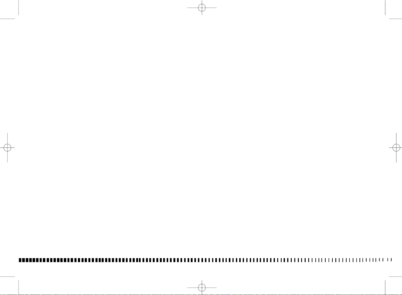
DATI PER
L’IDENTIFICAZIONE (Fig. 1)
Il veicolo é identificato da:
- numero di matricola del
motociclo riportato sulla destra
del cannotto di sterzo;
- numero di matricola del motore
riportato sulla parte superiore
del semicarter sinistro;
- codice del colore riportato sulla
targhetta applicata sul telaietto
posteriore, a fianco della
batteria (per accedervi è
necessario ruotare in senso
antiorario il perno posteriore (4),
rimuoverlo ed estrarre la sella).
Riferite sempre, in sede di
ordinazione dei ricambi, il n° di
matricola del motociclo ed il
codice del colore. Annotate
questo codice anche sul
presente libretto, in modo da
poterlo ricordare in caso di
distacco della targhetta adesiva.
IDENTIFICATION DATA
(Fig. 1)
The motorcycle is identified by:
- serial number of the motorcycle
stamped on the steering tube
right side;
- serial number of the engine
stamped on the upper part of
the left half crankcase;
- colour code stamped on the
plate placed on the frame, to
the side of battery (to gain
access to it, turn rear pin (4)
anticlockwise, remove the pin
then the saddle).
When ordering spare parts do
not forget to state the
motorcycle serial number and
the color code.
Write this code on the present
owner’s manual so as to
remember it should the adhesive
plate come off.
DONNÉEES D’IDENTIFICATION
(Fig. 1)
La moto est identifiée par:
- numéro matricule de la moto
gravé à droite du guidon;
- numéro matricule du moteur
gravé à la partie supérieure du
demi-carter gauche;
- code couleur gravé sur la
plaque appliquée au cadre, a
côté de la batterie (pour
accéder, tourner en sens
antihoraire le pivot arrière (4) et
ôter la selle).
Se référer toujours au numéro
matricule et au code couleur
pour la commande de pièces de
rechange.
Annotez ce code sur votre livret
pour l’avoir sous la main au cas
ou la plaque est égarée.
IDENTIFIZIERUNGSDATEN
(Bild. 1)
Das Motorrad wird mit den
folgenden Kennnummern
identifiziert:
- Rahmen-Nummer auf der
rechten Seite des Steuerrohrs;
- Motor-Nummer auf dem
oberen Teil der linksseitigen
Kastenhälfte;
- Farbbezeichnung auf dem
Rahmen neben der Batterie
(den hinteren Zapfen (4) gegen
den Uhrzeigersinn drehen ; den
Zapfen abnehmen und den
Sattel entfernen).
Bei der Bestellung von
Ersatzteilen geben Sie immer die
Rahmen-Nummer und die
Farbbezeichnung an. Tragen Sie
die Farbbezeichnung in dieses
Handbuch ein, damit sie auch im
Falle einer Entfernung des
Schildes von der Haube nicht
verloren geht.
CODICE COLORE....................
12
COLOR CODE..........................
CODE COULEUR.....................
FARBBEZEICHNUNG.............
Page 15
1-Dual Purpose 125-09 14-01-2009 16:35 Pagina 13
DATOS PARA LA IDENTIFICACION (Fig. 1)
El vehículo está identificado
por:
- número de matrícula de la moto
que se encuentra a la derecha
del tubo de direccíón;
- número de matrícula del motor
que se encuentra en la parte
superior del semicárter
izquierdo;
- código del color que se
encuentra en la placa aplicada
en el bastidor al lado de la
batería (para aceder al mismo
es necesario girar en sentido
antihorario el perno trasero (4),
retirarlo y extraer el sillín).
Refiera siempre, cuando haga el
pedido de los recambios,
el n° de matrícula de la
moto y el código del color.
Anote este código también
en este folleto a fin de poder
recordarlo en caso de que
se despegue la placa adhesiva.
CODIGO COLOR......................
FIG. 1
1. Matricola motociclo
2. Matricola motore
3. Targhetta codice colore
4. Perno fiss. sella
FIG. 1
1. Motorcycle serial number
2. Engine serial number
3. Color code decal
4. Saddle fastening pin
FIG. 1
1. Matricule moto
2. Matricule moteur
3. Plaque code couleur
4. Pivot de fixation selle
BILD 1
1. Rahmen-Nr.
2. Motor-Nr.
3. Schild mit Farbbezeichnung
4. Befestigungszapfen für Sattel
FIG. 1
1. Matrícula moto
2. Matrícula motor
3. Placa código color
4. Perno fijación sillín
13
Page 16

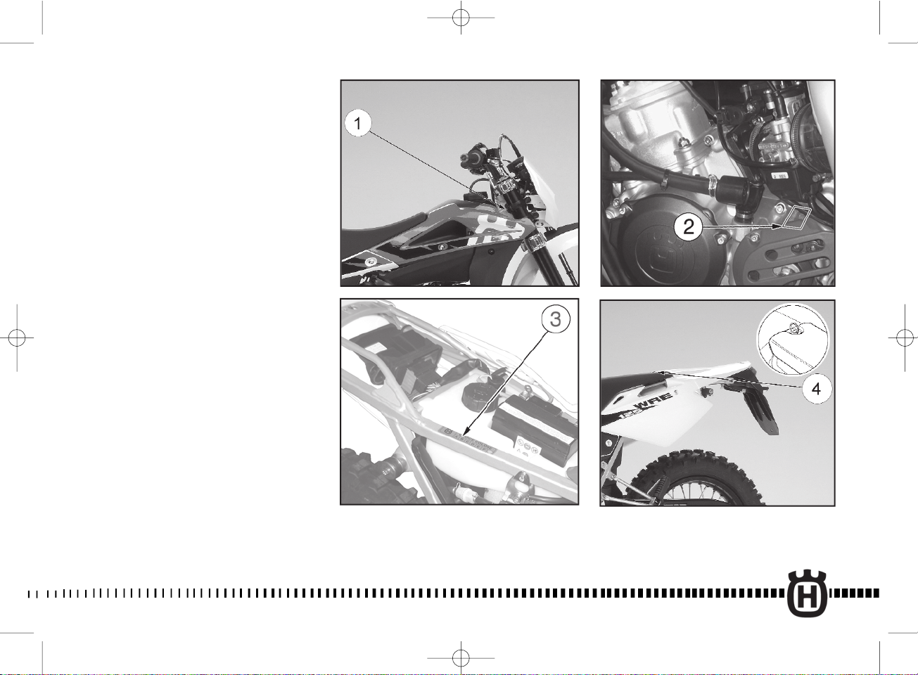
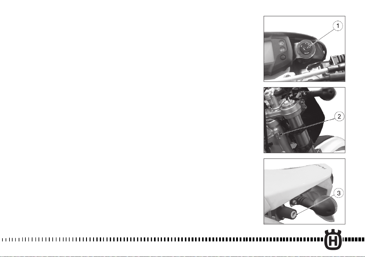
CHIAVI
Con il motociclo vengono consegnate due
chiavi (una di riserva) che consentono di
intervenire su interruttore di accensione (1),
bloccasterzo (2) e serratura casco (3).
KEYS
The motorcycle is supplied with two
wrenches (one is a reserve) for intervention
on ignition switch (1), steering lock (2) and
helmet lock (3).
CLES
La moto est dotée de deux clés (une de
réserve) pour intervenir sur l’interrupteur
d’allumage (1), verrou de direction (2) et
serrure casque (3).
Nota*: Conservare la chiave di riserva in
luogo sicuro.
DATI TECNICI
MOTORE
Tipo............................monocilindrico 2 tempi
con aspirazione lamellare nel basamento e
valvola H.T.S. a comando meccanico sullo
scarico
Raffreddamento................................a liquido
Alesaggio.............................................mm 54
Corsa ...............................................mm 54,5
Cilindrata .....................................cm
3
124,82
Rapporto di compressione (a luci chiuse) ..8,8:1
Avviamento ......................................a pedale
LUBRIFICAZIONE
Motore ..........................mediante pompa olio
...........................................................elettrica
Trasmissione primaria/
Cambio velocità...............................mediante
l'olio contenuto nel basamento
ACCENSIONE
Tipo .....................................Elettronica C.D.I.
Candela tipo.......................... “NGK” BR9 EG
oppure "CHAMPION" QN 84
Distanza elettrodi .............................. mm 0,6
Note*: Preserve the spare key in a safe
place.
TECHNICAL DATA
ENGINE
Type.....................two-strokes single cylinder
by lamellar suction in the crankcase and
mechanical
controlled H.T.S. valve on the exhaust
Cooling .............................................by liquid
Bore ...................................................2.12 in.
Stroke ................................................2.14 in.
Piston Displacement .....................7.61 cu.in.
Compression ratio (at closed ports) .......8,8:1
Starting ...........................................kick-start
LUBRICATION
Engine .................................by electric pump
Primary drive transmission/
Gearbox ..............................by oil contained
in the crankcase
IGNITION
Type .....................................Electronic, C.D.I.
Spark Plug Type . ............. “NGK” BR9 EG or
"CHAMPION" QN 84
Gap . ..............................................0.0236 in.
Nota*: Garder la clé de réserve dans un
lieu sûr.
DONNEES TECHNIQUES
MOTEUR
Type ....................monocylindrique à 2 temps
avec admission lamellaire dans le
soubassement et
soupape H.T.S. à commande
mécanique sur l’échappement
Refroidissement.............................par liquide
Alésage...............................................mm. 54
Course ............................................mm. 54,5
Cylindrée......................................cm3124,82
Rapport volumetrique
(avec orifices fermés)..............................8,8:1
Démarrage ........................................à pédale
LUBRIFICATION
Moteur .............par pompe à huile electrique
Transmission principale/
Boîte de vitesses ............par l’huile du carter
ALLUMAGE
Type .................................électronique, C.D.I.
Bougie type ................... “NGK” BR9 EG ou
"CHAMPION" QN 84
Distance électrodes ...........................mm 0,6
14
Page 17
SCHLÜSSEL
Mit dem Motorrad werden zwei
Schlüsselsätze beigeliefert für Lenkschloss
(1), Lenkschloss (2) und Helm schloss (3).
LLAVES
Junto con la moto se entregan dos llaves
que permiten intervenir en interruptor de
encendido (1), cerradura del manillar (2) y
cerradura casco (3).
Anmerkung* : Den Reserveschlüssel an
einem sicheren Platz verwahren.
TECHNISCHE DATEN
MOTOR
Typ .............................ein 2-Takt-Zylinder mit
Lamellenansaugung im Kurbelgehäuse und
mechanisch-betaetigtes H.T.S.- Ventil auf
dem Auspuff
Kühlung ..................................mit Flüssigkeit
Bohrung .............................................mm 54
Hub .................................................mm 54,5
Gesamthubraum ..........................cm3124,82
Verdichtungsverhältnis
(mit geschlossenen Schlitzen)................8,8:1
Anlassen .........................................mit Pedal
SCHMIERUNG
Motor .................durch Elektrische Ölpumpe
Primärübersetzung/
Wechselgetriebe .....................mittels des im
Kurbelgehäuse enthaltenen Öls
ZÜNDUNG
Typ ..................................Elektronisch, C.D.I.
Zündkerze Typ ............ “NGK” BR9 EG oder
"CHAMPION" QN 84
Elektrodenabstand .............................mm 0,6
Nota*: guardar la llave de reserva en un
sitio seguro.
FICHA TECNICA
MOTOR
Tipo ..........monocilíndrico de 2 tiempos con
aspiración laminar en la bancada y válvula
H.T.S.
de mando macánico en el escape
Enfriamiento ................................por líquido
Diámetro cilindros .............................mm 54
Carrera ............................................mm 54,5
Cilindrada ...................................cm3124,82
Relación de compresión
(con las lumbreras cerradas) ................. 8,8:1
Arranque ......................................de pedale
LUBRICACION
Motor .............mediante mediante bomba eléctrica
Transmisión primaria/
Cambio de velocidad .................mediante el
aceite que contiene la bancada
ENCENDIDO
Tipo .................................Electrónico, C.D.I.
Bujía tipo.....................“NGK” BR9 EG o bien
"CHAMPION" QN 84
Distancia electrodos .........................mm 0,6
15
Page 18

ALIMENTAZIONE
Carburatore ...........DELL’ORTO VHST 28-CS
Diametro diffusore...............................mm 28
Getto massimo ........................................142
Getto minimo .........................................U 38
Getto starter ...............................................60
Valvola gas ................................................55
Spillo conico .........................................D 48
Tacca fiss. spillo conico ......................... 2ª(*)
Polverizzatore.................................... HN 268
Galleggiante ...........................................g 6,5
Vite aria aperta di giri ...............................1.5
CARBURETOR
Carburetor ............DELL’ORTO VHST 28-CS
Venturi Diameter .................................1.10 in
High Speed Jet. ......................................142
Low Speed Jet . .................................... U 38
Starter jet....................................................60
Throttle Piston......................................... . 55
Metering Pin . ........................................D 48
Metering Pin position . .......................2 nd (*)
Main nozzle ........................................HN 268
Float .......................................................g 6,5
Idle Mixture Adjusting Screw . .................1,5
ALIMENTATION
Carburateur .......... DELL’ORTO VHST 28-CS
Diamètre diffuseur ...............................mm 28
Gicleur principal........................................142
Gicleur relenti..........................................U 38
Gicleur starter.............................................60
Soupape gaz ..............................................55
Epingle conique ......................................D 48
Coche fixation épingle conique.........2ème (*)
Pulverisateur.......................................HN 268
Flotteur ...................................................g 6,5
Vis air ouverte de tours..............................1,5
(*): con rondella tra fermaglio e valvola gas
TRASMISSIONE PRIMARIA
Pignone motore .....................................z 22
Corona frizione .......................................z 72
Rapporto di trasmissione ....................3,272
CAMBIO
Tipo: .......................................con ingranaggi
sempre in presa
Rapporti di trasmissione:
in 1ª velocità ..........................(Z 35/13) 2,692
in 2ª velocità .........................(Z 27/15) 1,800
in 3ª velocità .........................(Z 24/18) 1,333
in 4ª velocità .........................(Z 22/20) 1,100
in 5ª velocità .........................(Z 21/22) 0,954
in 6ª velocità .........................(Z 20/23) 0,869
TRASMISSIONE SECONDARIA (wre)
Pignone uscita cambio ..........................z 13
Corona sulla ruota .................................z 49
Rapporto di trasmissione .................... 3,769
Catena di trasmissione .................5/8’’x1/4’’
16
(*): with washer between retainer and throttle
valve
PRIMARY DRIVE
Drive pinion Gear ....................................z 22
Clutch ring Gear . ...................................z 72
Ratio .....................................................3.272
TRANSMISSION
Type: ...............................constant mesh gear
Ratios:
1st . .......................................(Z 35/13) 2.692
2nd . ......................................(Z 27/15) 1.800
3rd .........................................(Z 24/18) 1.333
4th . .......................................(Z 22/20) 1.100
5th . .......................................(Z 21/22) 0.954
6th . .......................................(Z 20/23) 0.869
SECONDARY DRIVE (wre)
Transmission sprocket . ...........................z 13
Rear wheel sprocket . .............................z 49
Ratio . ...................................................3.769
Chain . ...........................................5/8’’x1/4’’
(*): avec rondelle entre bague d’arret et
soupapa gaz
TRANSMISSION PRINCIPALE
Pignon moteur .........................................z 22
Couronne embrayage ..............................z 72
Rapport de transmission .......................3,272
BOITE DE VITESSES
Type: .....................avec engrenages en prise
constante
Rapports de transmission:
en 1ère vitesse ......................(Z 35/13) 2,692
en 2ème vitesse ....................(Z 27/15) 1,800
en 3ème vitesse ....................(Z 24/18) 1,333
en 4ème vitesse ....................(Z 22/20) 1,100
en 5ème vitesse ....................(Z 21/22) 0,954
en 6ème vitesse ....................(Z 20/23) 0,869
TRANSMISSION SECONDAIRE (wre)
Pignon sortie boîte de vitesses .............. z 13
Couronne sur la roue ..............................z 49
Rapport de transmission ......................3,769
Chaîne d’entraînement ...................5/8’’x1/4’’
Page 19

ZUFÜHRUNG
Vergaser.................DELL’ORTO VHST 28-CS
Luftdüse-Durchmesser .......................mm 28
Höchstdrehzahldüse ................................142
Leerlaufdüse ...........................................U 38
Starterkraftstoffdüse...................................60
Gasdrossel .................................................55
Kegelnadel..............................................D 48
Kegelnadelstellung...................................2.(*)
Einspritzdüse......................................HN 268
Schwimmer............................................g 6,5
Starterschraube
gelockert um Drehungen ..........................1,5
ALIMENTACION
Carburador ..........DELL’ORTO VHST 28-CS
Diámetro difusor ................................mm 28
Surtidor máximo .....................................142
Surtidor mínimo ......................................U 38
Surtidor starter ...........................................60
Válvula de mariposa .................................55
Espiga cónica ........................................D 48
Muesca fij. espiga cónica .....................2ª (*)
Pulverizador........................................HN 268
Flotador ..................................................g 6,5
Tornillo aire abierto de rev. .......................1,5
(*): mit Scheibe zwischen Seeger Ring und
Gasdrossel
PRIMÄRÜBERSETZUNG
Antriebsritzel ...........................................z 22
Kupplungskranz ......................................z 72
Übersetzungsverhältnis ........................3,272
WECHSELGETRIEBE
Typ: ......mit Zahnrädern in ständigem Eingriff
Übersetzungsverhältnisse:
1. Gang .................................(Z 35/13) 2,692
2. Gang .................................(Z 27/15) 1,800
3. Gang .................................(Z 24/18) 1,333
4. Gang .................................(Z 22/20) 1,100
5. Gang .................................(Z 21/22) 0,954
6. Gang .................................(Z 20/23) 0,869
SEKUNDÄRÜBERSETZUNG (wre)
Abtriebsritzel ..........................................z 13
Wechselradkranz ....................................z 49
Übersetzungsverhältnis .......................3,769
Antriebskette ................................5/8’’x1/4’’
(*): con arandela entre anillo de retención y
válvula gas
TRANSMISION PRIMARIA
Piñón motor ...........................................z 22
Corona embrague ..................................z 72
Relación de transmisión ......................3,272
CAMBIO
Tipo .........de engranajes de toma constante
Relaciones de transmisión:
en 1° velocidad .....................(Z 35/13) 2,692
en 2° velocidad .....................(Z 27/15) 1,800
en 3° velocidad .....................(Z 24/18) 1,333
en 4° velocidad .....................(Z 22/20) 1,100
en 5° velocidad .....................(Z 21/22) 0,954
en 6° velocidad .....................(Z 20/23) 0,869
TRANSMISION SECUNDARIA (wre)
Piñón salida cambio ..............................z 13
Corona en la rueda ................................z 49
Relación de transmisión ......................3,769
Cadena de transmisión .................5/8’’x1/4’’
17
Page 20

TRASMISSIONE SECONDARIA (sms)
Pignone uscita cambio ..........................z 14
Corona sulla ruota .................................z 49
Rapporto di trasmissione .................... 3,500
Catena di trasmissione .................5/8’’x1/4’’
RAPPORTI TOTALI
DI TRASMISSIONE (wre)
in 1ª velocità ......................................33,211
in 2ª velocità ...................................... 22,204
in 3ª velocità ...................................... 16,447
in 4ª velocità ......................................13,569
in 5ª velocità ......................................11,775
in 6ª velocità .......................................10,727
SECONDARY DRIVE (sms)
Transmission sprocket ............................z 14
Rear wheel sprocket . .............................z 49
Ratio . ...................................................3.500
Chain . ...........................................5/8’’x1/4’’
FINAL RATIOS (wre)
1st . .................................................... 33,211
2nd ................................................... 22,204
3rd . ....................................................16,447
4th . .....................................................13,569
5th ..................................................... 11,775
6th ................................................... 10,727
TRANSMISSION SECONDAIRE (sms)
Pignon sortie boîte de vitesses .............. z 14
Couronne sur la roue ..............................z 49
Rapport de transmission ......................3,500
Chaîne d’entraînement ...................5/8’’x1/4’’
RAPPORTS TOTAUX
DE TRANSMISSION (wre)
en 1ère vitesse ....................................33,211
en 2ème vitesse ................................ 22,204
en 3ème vitesse ..................................16,447
en 4ème vitesse ..................................13,569
en 5ème vitesse ..................................11,775
en 6ème vitesse ..................................10,727
RAPPORTI TOTALI
DI TRASMISSIONE (sms)
in 1ª velocità ......................................30,839
in 2ª velocità ...................................... 20,618
in 3ª velocità ...................................... 15,273
in 4ª velocità ......................................12,600
in 5ª velocità ......................................10,934
in 6ª velocità .........................................9,960
TELAIO
Tipo.........a doppia culla; telaietto posteriore.
Tubi rettangolari e quadrati di
acciaio ad alta resistenza.
SOSPENSIONE ANTERIORE
Tipo .....forcella teleidraulica a steli rovesciati
e perno avanzato. Steli Ø 41 mm.
Corsa sull’asse gambe 271 mm.
SOSPENSIONE POSTERIORE
Tipo ......................SOFT DAMP progressiva.
Mono ammortizzatore idraulico
con molla a precarica regolabile.
Corsa ruota 290 mm (wre)
282 mm (sms)
18
FINAL RATIOS (sms)
1st . .................................................... 30,839
2nd .................................................... 20,618
3rd . ....................................................15,273
4th . .....................................................12,600
5th ..................................................... 10,934
6th ..................................................... 9,960
FRAME
Type . ................... double-cradle; rear frame.
Made up of rectangular and square
high tensile steel tubes.
FRONT SUSPENSION
Type ............... telescopic-hydraulic fork with
reserved rods and
advanced axle. Stems diam. 1.61 in..
Stroke on the legs axis 10.67 in.
REAR SUSPENSION
Type ..................................progressive SOFT
DAMP with hydraulic single
damper and adjustable preload spring
Wheel stroke 11.4 in. (wre)
11.1 in. (sms)
RAPPORTS TOTAUX
DE TRANSMISSION (sms)
en 1ère vitesse ....................................30,839
en 2ème vitesse ................................. 20,618
en 3ème vitesse ..................................15,273
en 4ème vitesse ..................................12,600
en 5ème vitesse ..................................10,934
en 6ème vitesse ....................................9,960
CADRE
Type ..............double-berceau; cadre arrière.
Tubes rectangulaires et carrés d’acier
à haute résistance
SUSPENSION AVANT
Type ........fourche télescopique- hydraulique
à fourreaux renversés et pivot avancé.
Fourreaux diam 41 mm.
Course verticale 271 mm.
SUSPENSION ARRIERE
Type ......................SOFT DAMP progressive.
Monoamortisseur hydraulique avec ressort à
précharge réglable.
Course de la roue 290 mm. (wre)
282 mm (sms)
Page 21

SEKUNDÄRÜBERSETZUNG (sms)
Abtriebsritzel ..........................................z 14
Wechselradkranz ....................................z 49
Übersetzungsverhältnis .......................3,500
Antriebskette ................................5/8’’x1/4’’
TRANSMISION SECUNDARIA (sms)
Piñón salida cambio ..............................z 14
Corona en la rueda ................................z 49
Relación de transmisión ......................3,500
Cadena de transmisión .................5/8’’x1/4’’
GESAMTÜBERSETZUNGSVERHÄLTNISSE (wre)
1. Gang .............................................. 33,211
2. Gang ............................................. 22,204
3. Gang ..............................................16,447
4. Gang ...............................................13,569
5. Gang ..............................................11,775
6. Gang ..............................................10,727
GESAMTÜBERSETZUNGSVERHÄLTNISSE (sms)
1. Gang .............................................. 30,839
2. Gang ...............................................20,618
3. Gang ...............................................15,273
4. Gang ...............................................12,600
5. Gang ..............................................10,934
6. Gang .................................................9,960
RAHMEN
Typ ..............Doppelwiege, hinterer Rahmen.
Rechteckige und viereckige hochfeste
Stahlrohre.
VORDERRADFEDERUNG
Typ.......................Telehydraulische Gabel mit
vorgeschobenem Zapfen und
Stangendurchmesser Ø 41 mm
Hub auf der Beinachse 271 mm
HINTERRADFEDERUNG
Typ .........................Progressive SOFT DAMP.
Hydraulischer Einstossdämpfer mit
verstellbarer Vorspannung.
Radhub 290 mm. (wre)
282 mm (sms)
RELACIONES TOTALES
DE TRANSMISION (wre)
en 1° velocidad ................................. 33,211
en 2° velocidad ..................................22,204
en 3° velocidad ..................................16,447
en 4° velocidad ..................................13,569
en 5° velocidad ..................................11,775
en 6° velocidad ..................................10,727
RELACIONES TOTALES
DE TRANSMISION (sms)
en 1° velocidad ..................................30,839
en 2° velocidad ..................................20,618
en 3° velocidad ..................................15,273
en 4° velocidad ..................................12,600
en 5° velocidad ..................................10,934
en 6° velocidad ....................................9,960
BASTIDOR
Tipo ...........de doble cuna; bastidor trasero.
Tubos rectangulares y
cuadrados de acero de alta resistencia.
SUSPENSION DELANTERA
Tipo ...........................horquilla telehidráulica
vástagos invertidos y de perno avanzado.
Vástagos diám. Ø 41 mm.
Carrera en el eje de las patas 271 mm.
SUSPENSION TRASERA
Tipo ......................Progressiva SOFT DAMP.
Monoamortiguador hidráulico
con resorte de precarga regulable.
Carrera de la rueda 290 mm (wre)
282 mm (sms)
19
Page 22

FRENO ANTERIORE
Tipo ..........a disco fisso diametro Ø 260 mm
con comando idraulico; pinza flottante.
FRONT BRAKE
Type ..........................fixed disc 10.24 in. dia.
with hydraulic control; floating caliper.
FREIN AVANT
Type ..................à disque fixe diam. 260 mm.
avec commande hydraulique;
étrier flottant.
FRENO POSTERIORE
Tipo ..........................a disco fisso Ø 220 mm
con comando idraulico; pinza flottante.
CERCHIO ANTERIORE
Tipo ....................................... in lega leggera
Dimensioni .......................... 1,60’’x21’’ (wre)
2,75”x17” (sms)
CERCHIO POSTERIORE
Tipo ....................................... in lega leggera
Dimensioni .......................... 2,15’’x18’’ (wre)
4,25”x17” (sms)
PNEUMATICO ANTERIORE
Marca e tipo (wre) ..................... Pirelli MT 21
Marca e tipo (sms) "DUNLOP" D 208-F oppure
...................................."PIRELLI" Diablo 54H TL
Dimensioni (wre) ........................... 90/90/21”
Dimensioni (sms) ........................ 110/70-17”
Pressione di gonfiaggio a freddo Kg/cm
2
1,2
psi 17,1
Pressione di gonfiaggio a
freddo con passeggero.................kg/cm
2
1,5
psi 21,3
REAR BRAKE
Type ............................fixed disc 8.66 in. dia.
with hydraulic control; floating caliper.
FRONT RIM
Type .......................................... in light alloy
Size ......................................1.60’’x21’’ (wre)
2,75”x17” (sms)
REAR RIM
Type .......................................... in light alloy
Size ..................................... 2.15’’x18’’ (wre)
4,25”x17” (sms)
FRONT TIRE
Make and type (wre) .................Pirelli MT 21
Make and type (sms)"......."DUNLOP" D 208-F or
........................................"PIRELLI" Diablo 54H TL
Tire Size (wre)................................90/90/21”
Tire Size (sms) .............................110/70-17”
Cold tire pressure . ......................Kg/cm
Cold pressure with passenger .....Kg/cm
2
1.2
psi 17.1
2
1.5
psi 21.3
FREIN ARRIERE
Type...................à disque fixe diam. 220 mm.
avec commande hydraulique;
étrier flottant.
JANTE AVANT
Type ...................................... en alliage léger
Dimensions ......................... 1,60"x21’’ (wre)
2,75”x17” (sms)
JANTE ARRIERE
Type ..................................... en alliage léger
Dimensions ..........................2,15"x18’’’ (wre)
4,25”x17” (sms)
PNEU AVANT
Marque et type (wre).................Pirelli MT 21
Marque et type (sms)......."DUNLOP" D 208-F ou
...................................."PIRELLI" Diablo 54H TL
Dimensions (wre) ...........................90/90/21”
Dimensions (sms) ........................110/70-17”
Pression de gonflage à froid ........Kg/cm
2
1,2
psi 17,1
Pression de gonflage à froid
avec passeger ..............................Kg/cm
2
1,5
psi 21.3
20
Page 23

VORDERRADBREMSE
Typ .......................mit stationärer hydraulisch
getriebener Scheibe Durchmesser
Ø 260 mm; Schwebzange.
FRENO DELANTERO
Tipo ...............de disco fijo diám. Ø 260 mm
de mando hidráulico, pinza flotante.
HINTERRADBREMSE
Typ .......................mit stationärer hydraulisch
FRENO TRASERO
Tipo ...............de disco fijo diám. Ø 220 mm
getriebener Scheibe Durchmesser
Ø 220 mm; Schwebzange.
VORDERRADFELGE
Typ ............................................. Leichtmetal
Abmessungen.......................1,60’’x21’’ (wre)
LLANTA DELANTERA
Tipo ...................................... aleacin liviana.
Dimensiones ......................1,60’’x21’’ (wre)
2,75”x17” (sms)
HINTERRADFELGE
Typ.............................................. Leichtmetal
Abmessungen.......................2,15’’x18’’ (wre)
LLANTA TRASERA
Tipo .......................................aleacin liviana.
Dimensiones .......................2,15’’x18’’ (wre)
4,25”x17” (sms)
VORDERREIFEN
Bezeichnung und Typ (wre) .......Pirelli MT 21
Bezeichnung und Typ (sms)..."DUNLOP" D 208-F oder
...................................................."PIRELLI" Diablo 54H TL
Abmessungen (wre).......................90/90/21”
Abmessungen (sm) ....................110/70-17”
Kaltluftdruck ................................Kg/cm
Kaltluftdruck mit Fahrer ...............Kg/cm
2
psi 17,1
2
psi 21,3
NEUMATICO DELANTERO
Marca y tipo (wre) ......................Pirelli MT 21
Marca y tipo (sms).
...................................."PIRELLI" Diablo 54H TL
Dimensiones (wre)..........................90/90/21”
Dimensiones (sms).......................110/70-17”
1,2
Presión de inflado en frío ...........Kg/cm
1,5
Presión de inflado en frío
con pasajero.................................Kg/cm
de mando hidráulico, pinza flotante.
2,75”x17” (sms)
4,25”x17” (sms)
"DUNLOP" D 208-F o bien
2
1,2
psi 17,1
2
1,5
psi 21,3
21
Page 24
1-Dual Purpose 125-09 14-01-2009 16:35 Pagina 22
PNEUMATICO POSTERIORE
Marca e tipo (wre) ..................... Pirelli MT 83
Marca e tipo (sms)
"DUNLOP" D 207-TL ........
.......................oppure "PIRELLI" Diablo 66H TL
Dimensioni (wre) ......................... 120/90/18”
Dimensioni (sms) ........................ 150/60-17”
Pressione di gonfiaggio a freddo Kg/cm
2
1,5
psi 21,3
Pressione di gonfiaggio
a freddo con passeggero .......... Kg/cm
2
1,8
psi 25,5
DIMENSIONI, PESO, CAPACITÀ
mm
Interasse................................. (wre)
................................................(sms)
Lunghezza totale
.............................................................
................................
(wre)
(sms)
Larghezza massima ..................(wre)
..............................................................
Altezza massima ............................
......................................................
(sms)
(wre)
(sms)
1475
mm
1470
mm 2250
mm 2210
mm
825
mm
825
mm 1245
mm 1175
Altezza sella .............................(wre) mm935
mm
..................................................(sms)
Altezza minima da terra ...................
........................................................
(wre)
(sms)
870
mm 330
mm 265
Peso in ordine di marcia, senza carburante ...
................................................(wre) Kg 111,1
................................................(sms) Kg 113,5
Capacità serbatoio carburante................ 9,5
(Compresa una riserva di l. 2)
Capacità serbatoio olio ........................... 0,8
Olio nel basamento ................................ 0,65
Liquido circuito di raffreddamento ........... l. 1
Olio in ogni stelo forcella .....................390 cc
REAR TIRE
Make and type (wre) ................. Pirelli MT 83
Make and type (sms)
"DUNLOP" D 207-TL or
...................................."PIRELLI" Diablo 66H TL
Tire Size (wre)..............................120/90/18”
Tire Size (sms) ............................150/60-17”
Cold tire pressure ........................Kg/cm
2
1.5
psi 21.3
Cold tire pressure
with passenger . ..........................Kg/cm
2
1.8
psi 25.5
DIMENSIONS, WEIGHT, CAPACITIES
Wheelbase.................................
.................................................
Overall length
.....................................88.58 in.
58.07 in.
57.87 in.
...................................................................87 in.
Overall width ............................
32.48 in.
...............................................................32.48 in.
Overall height
.................................49.01 in.
.......................................................46.26 in.
Saddle height ..........................
.................................................
Minimum ground clearance 12.8 in.
36.81 in.
34.25 in.
...........13 in.
.............................................................10.43
Kerb weight, without fuel ..........
.................................................
244.9 ib.
250.2 ib.
(wre)
(sms)
(wre)
(sms)
(wre)
(sms
(wre)
(sms)
(wre)
(sms)
(wre)
(sms)
(wre)
(sms)
Fuel tank capacity . ................2.09 Imp. Gall.
(1.58 Imp. 0.44 Imp. Qt. reserve included)
Oil tank capacity . .......................0.7 Imp. Qt.
Crankcase oil ............................0.57 Imp. Qt.
Coolant . ...................................0.88 Imp. Qt.
Oil in each fork rod.........................23.8 cu.in.
PNEU ARRIERE
Marque et type (wre)..................Pirelli MT 83
Marque et type (sms)
"DUNLOP" D 207-TL ou
.................................. "PIRELLI" Diablo 66H TL
Dimensions (wre) .........................120/90/18”
Dimensions (sms) .......................150/60-17”
Pression de gonflage à froid ........Kg/cm
2
1,5
psi 21,3
Pression de gonflage
à froid avec passager...................Kg/cm
2
1,8
psi 25,5
DIMENSIONS, POIDS, CAPACITE
mm
Empattement.......................... (wre)
................................................(sms)
Longueur totale
................................
.............................................................
(wre)
(sms)
Largeur maxi .............................(wre)
..............................................................
Hauteur maxi
................................
......................................................
(sms)
(wre)
(sms)
1475
mm
1470
mm 2250
mm 2210
mm
825
mm
825
mm 1245
mm 1175
Hauteur selle ............................(wre) mm935
mm
..................................................(sms)
Garde au sol mini
..........................
........................................................
(wre)
(sms)
870
mm 330
mm 265
Poids en orde de marche,sans carburant ......
................................................(wre) Kg 111,1
................................................(sms) Kg 113,5
Contenance réservoir d’essence ............ 9,5
(Comprise una réserve de l. 2)
Capacité réservoir d’huile ...................... . 0,8
Huile carter ........................................... 0,65
Liquide circuit de refroidissement .......... . l. 1
Huile dans chaque fourreau.................390 cc
22
Page 25

HINTERREIFEN
Bezeichnung und Typ (wre) .......Pirelli MT 83
Bezeichnung und Typ (sms) .........
"DUNLOP" D 207-TL
........................................oder "PIRELLI" Diablo 66H TL
Abmessungen (wre).....................120/90/18"
Abmessungen (sms)....................150/60-17"
Kaltluftdruck.................................Kg/cm
Kaltluftdruck mit Fahrer .............Kg/cm
2
1,5
psi 21,3
2
1,8
psi 25,5
NEUMATICO TRASERO
Marca y tipo (wre) ......................Pirelli MT 83
Marca y tipo (sms)......
"DUNLOP" D 207-TL o
...........................bien "PIRELLI" Diablo 66H TL
Dimensiones (wre).......................120/90/18”
Dimensiones (sms).......................150/60-17”
Presión de inflado en frío ...........Kg/cm
2
1,5
psi 21,3
Presión de inflado en frío
con pasajero ...............................Kg/cm
2
1,8
psi 25,5
ABMESSUNGEN, GEWICHT, KAPAZITÄT
mm
Radabstand ............................ (wre)
................................................(sms)
Gesamtlänge
....................................
.............................................................
(wre)
(sms)
Max. Breite ...............................(wre)
..............................................................
Max. Höhe
....................................
......................................................
(sms)
(wre)
(sms)
1475
mm
1470
mm 2250
mm 2210
mm
825
mm
825
mm 1245
mm 1175
Sattelhöhe ................................(wre) mm935
mm
..................................................(sms)
Min. Höhe vom Bodeni
..................
........................................................
(wre)
(sms)
870
mm 330
mm 265
Fahrbereitwicht, ohne Treibstoff. (wre) Kg 111,1
................................................(sms) Kg 113,5
Kraftstoffbehälterkapazität .................... 9,5
(mit Kraftstoffreservel.2)
Ölbehälterkapazität ................................. 0,8
Öl im Kurbelgehäuse.............................. 0,65
Flüssigkeit im Kühlkreislauf ...................... l. 1
Oel in jedem Gabelschaft ....................390 cc
DIMENSIONES, PESO, CAPACIDAD
mm
Distancia entre ejes................ (wre)
................................................(sms)
Longitud tota
...................................
.............................................................
(wre)
(sms)
Anchura máxima ......................(wre)
..............................................................
Altura máxima
.............................
......................................................
(sms)
(wre)
(sms)
1475
mm
1470
mm 2250
mm 2210
mm
825
mm
825
mm 1245
mm 1175
Altura sillín ................................(wre) mm935
mm
..................................................(sms)
Altura mín. desde el suelo
........................................................
..................
(sms)
(wre)
870
mm 330
mm 265
Peso listo para marchar, sin carburante .........
................................................(wre) Kg 111,1
................................................(sms) Kg 113,5
Capacidad depósito carburante ............. 9,5
(Incluida una reserva de l. 2)
Capacidad depósito aceite ................... 0,8
Aceite en el cárter ................................. 0,65
Líquido circuito de enfriamiento ............. l. 1
Aceite en cada vástago de la horquilla 390 cc
23
Page 26

TABELLA DI LUBRIFICAZIONE /
Olio lubrificazione motore
TABLE FOR LUBRICATION
/ TABLEAU DE GRAISSAGE
Engine oil
Huile de graissage moteur........................................................... AGIP 2T FORMULA TEC
Olio lubrificazione cambio / Trasmissione primaria
Transmission / Primary drive oil
Huile de graissage boîte de vitesses / Transmission principale ..AGIP RACING 4T - 5W 40
Liquido refrigerante motore
Coolant
Liquide réfrigérant moteur ........................................................... AGIP COOL
Liquido impianti frenanti
Brakes fluid
Liquide système de freinage........................................................ AGIP BRAKE 4 (DOT 4)
Lubrificazione a grasso
Grease lubrication
Lubrification par graisse .............................................................. AGIP BIKE GREASE
Olio lubrificazione catena
Chain oil
Huile de graissage chaîne ........................................................... AGIP CHAIN LUBE
Olio forcella anteriore
Front fork oil
Huile fourche avant...................................................................... AGIP FORK 7,5 (SAE 7,5)
Protettivo contatti elettrici............................................................PAIOLI 600300011 (viscosità a 40°C=32)
Electric contact protection
Protection des contacts électriques ...........................................PAIOLI 600300011 (viscosité à 40°C=32)
Turafalle per radiatori ....................................................................................................
Fillers for radiator
Bouche-trous pour radiateurs ........................................................................................ liquido
..........................................................................................................
...............................................PAIOLI 600300011 (viscosity at 40°C/104°F=32)
AREXONS
TURAFALLE
24
Page 27
1-Dual Purpose 125-09 14-01-2009 16:35 Pagina 25
SCHMIERUNGSTABELLE
/ TABLA DE LUBRICACION
Motoröl
Aceite lubricación motor .............................................................. AGIP 2T FORMULA TEC
Getriebeöl/Primärübersetzung
Aceite lubricación cambio/Transmisión primaria ......................... AGIP RACING 4T- 5W 40
Kühlflüssigkeit
Líquido refrigerante motor ........................................................... AGIP COOL
Bremsflüssigkeit
Líquido instalación de frenado..................................................... AGIP BRAKE 4 (DOT 4)
Fettschmierung
Lubricación por grasa .................................................................. AGIP BIKE GREASE
Kettenöl
Aceite lubricación cadena............................................................ AGIP CHAIN LUBE
Vordergabelöl
Aceite horquilla delantera ............................................................
Schtmittel für elektrische Kontacte
De protección contactos eléctricos .........................................PAIOLI 600300011 (viscosidad a 40°C=32)
.......................................PAIOLI 600300011 (Viskosität bei 40° C=32)
AGIP FORK 7,5 (SAE 7,5)
Küler-Leckabdichtung .................................................................................................
Tapavías para radiatores.............................................................................................TURAFALLE líquido
AREXONS
25
Page 28

RUBINETTO CARBURANTE
COMANDI
(Fig. 2)
Il rubinetto posto sulla sinistra
del serbatoio consta di tre
posizioni:
OFF - chiuso; non c'è uscita di
carburante;
ON - aperto; il carburante esce
dal flusso principale;
RES - riserva; il carburante esce
dal flusso di riserva.
Qualora, durante la marcia, si
dovessero riscontrare difficoltà di
alimentazione porre la levetta del
rubinetto in posizione RES.
Prima di procedere
all’avviamento, porre la levetta
del rubinetto sulla posizione ON.
Ricordare di porre SEMPRE la
levetta sulla posizione OFF dopo
che si é usato il motociclo.
FUEL COCK
CONTROLS
(Fig. 2)
The cock set on left side of tank
has three positions:
OFF - closed; no fuel outlet;
ON - open; fuel outflows from
the main flow;
RES - reserve; fuel outflows from
the reserve flow.
When running, should feed
problem ensue, set cock lever on
RES position.
Before starting the engine, set
the lever in ON position.
Remember that the lever shall
ALWAYS be in OFF position after
stopping the motorcycle.
ROBINET D’ESSENCE
COMMANDES
(Fig. 2)
Le robinet placé à gauche du
réservoir a trois positions:
OFF - fermé; aucune sortie
d'essence;
ON - ouvert; l'essence sorte du
débit principal;
RES - réserve; l'essence sorte du
débit de la réserve.
Si pendant la marche des
problèmes d'alimentation sont
relevés, placer le levier du
robinet dans la position RES.
Avant le démarrage, placer le
levier du robinet sur ON.
Placer TOUJOURS le levier sur
OFF après l’utilisation de la
moto.
KRAFTSTOFFHAHN
BEDIENTEILE
(Bild 2)
Der Hahn auf der linken Seite des
Behaelters hat drei Stellungen:
OFF - zu; es tritt kein Treibstoff
aus;
ON - offen; der Treibstoff fliesst
aus der Hauptflussvorrichtung;
RES - Reserve; der Treibstoff
fliesst aus der Reserveflussvorrichtung aus. Sollte man
während des Fahrens auf
Versorgungsschwierigkeiten
stossen, den Hebel des Hahns
auf Stellung RES stellen.
Bevor man den Motor anläßt, ist
der Hebel auf ON zu stellen.
Nach Anhalten ist IMMER der
Hebel auf OFF zu drehen.
ATTENZIONE*: Fare attenzione
a non toccare il motore caldo
mentre si opera sul rubinetto
carburante.
26
WARNING*: Be careful not to
touch the hot engine while
operating the fuel valve.
ATTENTION * : Durant les
opérations sur le robinet
carburant, veillez à ne jamais
toucher le moteur chaud.
ACHTUNG * : Darauf achten,
während der Arbeit am
Treibstoffhahn nicht den
heißen Motor anzufassen.
Page 29
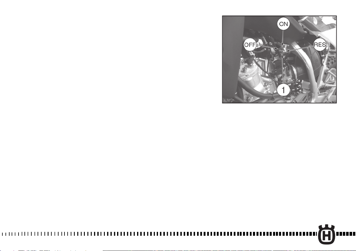
GRIFO DEL CARBURANTE
MANDOS
(Fig. 2)
El grifo colocado a la izquierda
del depósito consta de tres
posiciones:
OFF - cerrado; no sale
carburante;
ON - abierto; el carburante sale
del conducto principal;
RES - reserva; el carburante sale
del conducto de reserva.
En el caso de que durante la
marcha notara dificultades en la
alimentación, ponga la palanca
del grifo en posición RES.Antes
de arrancar ponga la
palanca del grifo en la posición
ON.
Acuérdese de colocar SIEMPRE
la palanca en la posición OFF
luego de usar la moto.
ATENCIÓN *: Tener cuidado a
no tocar el motor caliente
cuando se trabaja sobre el
grifo carburante.
FIG. 2
1. Rubinetto carburante
FIG. 2
1. Fuel cock
FIG. 2
1. Robinet d'essence
BILD 2
1. Kraftstoffhahn
FIG. 2
1. Grifo del carburante
27
Page 30

SERBATOIO CARBURANTE
(Fig. 2A)
In fase di rifornimento, è
consigliabile non far oltrepassare
al carburante il limite inferiore del
bocchettone di carico
assicurandosi sempre che,
terminata l’operazione, il tappo (1)
sia ben avvitato. Usate
esclusivamente benzina SENZA
PIOMBO.
Nota*:In presenza di
temperature inferiori a —5° C
rifornire il serbatoio con miscela
all’1% in luogo della sola
benzina.
ATTENZIONE*: La benzina è
estremamente infiammabile e
può diventare esplosiva in
particolari condizioni.
Spegnere sempre il motore,
non fumare o avvicinare
fiamme o scintille nell’area
dove si effettua il rifornimento
o si conserva il carburante.
STARTER CARBURATORE (FIG. 3)
Il dispositivo dello starter (1)
viene usato per arricchire la
miscela durante l’avviamento a
freddo.
Per attivarlo, spostare la levetta
dello starter nel senso indicato
dalla freccia; a motore caldo
disattivare lo starter.
Con motore caldo, non utilizzare
lo starter.
FUEL TANK
(Fig. 2A)
When filling up, do not exceed the
lower pipe unit limit and make
sure that once the operation is
done, the tap (1)is screwed tight.
Use UNLEAD FUEL only.
Note*: In presence of
temperatures lower than —5° C.
(23° F.), fill up the tank with 1%
mixture instead of petrol only.
WARNING*: Gasoline is extremely flammable and can be
explosive under certain conditions. Always stop the engine
and do not smoke or allow flames or sparks in the area
where the motorcycle is refueled or gasoline is stored.
CARBURETOR CHOKE LEVER
(Fig. 3)
The starting lever (1) is used ti
enrich the mixture during the
cold start.
To open it hold the choke lever in
the direction shown by the
arrow; with hot engine the choke
lever should be closed.
Never use the starter with
warmed up engine.
RESERVOIR D’ESSENCE
(Fig. 2A)
Au ravitaillement, ne pas dépasser
la limite inférieure de la goulotte
de chargement et l’operation
terminée, s’assurer toujours que le
bouchon (1) soit bien vissé.
Utilisez exclusivement ESSENCE
SANS PLOMB.
Avis*: En présence de
températures inférieures —5°C,
ravitailler avec mélange à l’1%
au lieu de la seule essence.
ATTENTION * : L’essence est
une matière très inflammable
que, dans des conditions
particulières, peut devenir
explosive. Arrêter toujours le
moteur, ne pas fumer, ou
approcher la flamme ou
étincelles à la zone de
ravitaillement, ou dans les lieux
où on garde le carburant.
STARTER CARBURATEUR
(Fig. 3)
Le dispositif du starter (1) est
utilisé pour enrichir le mélange
durant le démarrage à froid.
Pour l'activer, porter le levier du
starter dans le sens indiqué par
la flèche. Le moteur chaud,
désactiver le starter.
Ne jamais utiliser le starter avec
moteur chaud.
KRAFTSTOFFBEHÄLTER
(Bild. 2A)
Beim Auftanken ist es ratsam, die
untere Grenze des
Tankeinfüllstutzens mit dem
Kraftstoff nicht zu überschreiten;
am Ende der Betankung ist darauf
zu achten, dass der Stopfen (1)
fest verschraubt ist. Verwenden Sie
BLIEIFREIES BENZIN TANKEN.
Zur Beachtung*: Bei
Temperaturen unter —5° C
tanken Sie mit 1% Benzin-ÖlGemisch anstelle des Benzins
allein.
ACHTUNG* : Das Benzin ist
äußerst entzündbar und kann
unter besonderen Bedingungen
explosiv werden. Den Motor
immer abschalten, nicht rauchen
oder sich mit Flammen oder
Funken dem Bereich, an
welchem getankt oder Treibstoff
aufbewahrt wird, nähern.
VERGASERSTARTER (Bild 3)
Die Startvorrichtung (1) wird zur
Anreicherung der Mschung
während des Kalt-Anlassens
benutzt.
Luftgemisch beim Anlassen zu
überfetten. Die Startvorrichtung
wird beim Zichen des
Starterhebels in Pfeilrichtung in
Tätigkeit gesetzt; wenn der Motor
warm ist muß die
Startvorrichtung ausser Tätigkeit
gesetzt werden.
Den Starter nicht bei warmen
Motor benutzen.
28
Page 31

DEPOSITO CARBURANTE
(Fig. 2A)
Al repostar es conveniente que el
carburante no vaya más allá del
límite inferior de la boca de carga
asegurándose siempre que, una
vez terminada la operación, el
tapón (1) quede bien enroscado.
Use soloGASOLINA SIN PLOMO.
Nota*: En presencia de
temperaturas
inferiores a —5° C abastezca el
depósito con mezcla al 1% en
vez de usar solamente gasolina.
ATENCIÓN*: La gasolina es
extremamente inflamable y en
condiciones particulares puede
volverse explosiva. Apagar
siempre el motor, no fumar y no
acercar flamas o chispas en el
área en la que se efectúa la
provisión o se conserva el
carburante.
STARTER CARBURADOR
(Fig. 3)
El dispositivo del starter (1) se
usa para enriquecer la
mezcla durante el arranque en
frío.
Para activarlo, lleve la palanca
del starter en el sentido indicado
por la flecha; con motor caliente
desactive el starter.
Si el motor es caliente no
utilizar el starter. inversamente
para cerrar.
FIG. 2A
1. Tappo serbatoio carburante
FIG. 2A
1. Fuel tank tap
FIG. 2A
1. Bouchon reservoir d’essence
BILD 2A
1. Kraftstoffbehälterstopfen
FIG. 2A
1. Tapón deposito carburante
FIG. 3
1. Dispositivo starter
FIG. 3
1. Carburetor choke lever
FIG. 3
1. Starter
BILD 3
1. Startvorrichtung
FIG. 3
1. Dispositivo starter
29
Page 32

INTERRUTTORE ACCENSIONE (Fig. 4)
L’interruttore di accensione (1)
consta di tre posizioni.
Dalla posizione OFF, girare la chiave
in senso destrorso; nella prima
posizione IGNITION si avranno
inseriti l’accensione e gli utilizzatori,
nella seconda posizione si avranno
inserite le luci di parcheggio.
La chiave può essere estratta
soltanto nella posizione OFF e
quando sono inserite le luci di
parcheggio. In caso di smarrimento
di una delle due chiavi, approntarne
un’altra utilizzando la chiave
GREZZA che viene fornita a
ricambio.
IGNITION SWITCH - WARNING
LIGHTS - (Fig. 4)
The ignition switch (1) has three
positions:
From position OFF turn the key
rightwards; in the first IGNITION
position the start and the
instruments will be on; in the
second position the parking lights
will be on. The key can be extracted
when in OFF position only and
when the parking lights are on. If
one of the two keys gets lost, use
the ROUGH key supplied to make
another key.
COMMUTATEUR DE DEMAR-RAGE
(Fig. 4)
Le commutator de démarrage (1) a
trois positions:
En position OFF, tourner la clé en
sens horaire; dans la première
position IGNITION, seront insérés le
démarrage et les instruments; dans
la deuxième position, seront insérés
les feux de stationnement. La clé
peut être enlevée seulement en
position OFF et lorsque sont insérés
les feux de stationnement. Au cas où
une des deux clés est égarée, en
dresser une autre en utilisant la clé
BRUTE fournie.
ZÜNDSCHALTER KONTROLLEUCHTEN (Bild 4)
Der Zündschalter (1) hat drei Stellungen:
Befindet sich der Schlüssel auf OFF, muss
er nach rechts gedreht werden; in der
ersten Stellung, IGNITION, sind Zündung
und Hilfsapparate eingeschaltet; bei der
zweiten Stellung sind Parklichter
eingeschaltet. Der Schlüssel kann nur
abgezogen werden, wenn er sich bei der
OFF Stellung befindet und wenn die
Parklichter eingeschaltet sind. Falls ein
Schlüssel verloren geht, einen weitere
Schlüssel herstellen lassen und dazu den
rohen beigelieferten Schlüssel einsetzen.
Nota*: Quando si lascia il veicolo
incostudito, togliere sempre la
chiave dall’interruttore.
30
Note*: Always remove key from
ignition switch when motorcycle
is left unattended.
Avis*: Retirer toujours la clé de
démarrage lorsque vous laissez
votre moto sans surveillance.
Zur Beachtung*: Wenn Sie das
Motorrad unbeaufsichtigt lassen,
ziehen Sie immer den Schlüssel aus
dem Schalter ab Sollten Sie einen.
Page 33

INTERRUPTOR DE ENCENDIDO
(Fig. 4)
El interruptor de encedido (1) consta
de tres posiciones:
Desde la posición OFF gire la llave a
derechas; en la primera posición
IGNITION se conectarán el encedido y
los utilizadores; en la segunda
posición se conectarán las luces de
estacionamiento.
La llave se puede extraer sólo si se
encuentra en la posición OFF y
cuando están conectadas las luces de
estacionamiento.
En caso de que se extravie una de las
dos llaves, prepare otra utilizando la
llave SIN LABRAR que se entrega de
recambio.
Nota*: Si se deja el vehículo sin
vigilancia se debe quitar siempre la
llave del interruptor.
FIG. 4
1. Interruttore accensione
FIG. 4
1. Ignition switch
FIG. 4
1. Commutateur de démarrage
BILD 4
1. Zündschalter
FIG. 4
1. Interruptor de encedido
31
Page 34

2B-Dual Pourpose 125-09 14-01-2009 16:38 Pagina 32
STRUMENTO DIGITALE, SPIE
Il motociclo è equipaggiato con uno
strumento digitale sul quale sono
montate anche 5 spie indicatrici:
1- Spia BLU “Abbagliante”
2- Spia VERDE ”Luci”
3- Spia VERDE “Indicatori di
direzione”
4- Spia ROSSA “Riserva olio”
5- Spia ROSSA “Temperatura
refrigerante”
IMPORTANTE
Il motociclo è dotato di un “sistema
di sicurezza” che, in caso di
malfunzionamento, consente di
individuarne la causa. Sul display
(a) comparirà il codice relativo al
particolare difettoso (vedere figura):
rivolgetevi quindi al Concessionario
HUSQVARNA.
A. Pompa olio (*)
(*): RALLENTARE
IMMEDIATAMENTE. Dopo aver
rallentato, il motore si spegne
quando si raggiungono i 3000 giri/1’.
B. T.P.S. (Sensore posizione
valvola gas carburatore)
C. Valvola solenoide
D. Sensore temperatura acqua
E. Sensore temperatura aria
G: Limite max auto-apprendimenti
WARNING LIGHTS
The motorcycle is equipped with
a digital instrument; on the
instrument are located 5 warning
lights too:
1- BLUE warning light “HIGH BEAM”
2- GREEN warning light
”LIGHTS”
3- GREEN warning light
“BLINKERS”
4. RED light “Oil reserve”
5. RED light “Coolant
temperature”
IMPORTANT
The motorcycle is equipped with
a “safety system” that, in case of
malfunction, allows to determine
its cause. On display (a) will
appear the code concerning the
defective part (see picture):
contact your local HUSQVARNA
Dealer.
A. Oil pump (*)
(*): SLOW DOWN IMMEDIATELY.
After decelerating, the engine
stops once 3000 rpm is reached.
B. T.P.S. (Throttle Position
Sensor)
C. Solenoid valve
D. Water temperature sensor
E. Air temperature sensor
G: Auto-learning Overflow
INSTRUMENT DIGITAL, VOYANTS
Le motocycle est équipé avec un
instrument digital sur lequel sont
montées 5 voyants indicateurs
aussi:
1- Voyant BLEU “De route”
2- Voyant VERT ”Lumières”
3- Voyant VERT “Indicateurs de
direction”
4. Voyant ROUGE “Réserve d’huile”
5. Voyant ROUGE “Température
réfrigérant”
IMPORTANT
Le motocycle est doté d’un “système
de sûreté” que, en cas de mauvais
fonctionnement, il permet d’en
déterminer la cause. Sur le display
(a) paraîtra le code relatif au
particulier défectueux (voir
illustration): tournez-vous donc au
Concessionnaire HUSQVARNA.
A. Pompe huile (*)
(*): RALENTIR IMMÉDIATEMENT.
Après avoir ralenti, le moteur s’éteint
quand ils les atteignent les 3000
tours/1’.
B. T.P.S. (Capteur position du
papillon carburateur)
C. Soupape solénoide
D. Capteur pour temperature eau
E. Capteur pour temperature air
G: Maximum limite d'autoapprentissage
DIGITALTACHOMETER,
KONTROLLEUCHTEN
Das Motorrad wird mit einem
Digitaltachometer ausgerüstet auf
dem Stütze 5anzeigende
kontrolleuchten montierten auch:
1 - KONTROLLEUCHTE BLAU
“Fernlicht”
2 - KONTROLLEUCHTE GRÜN
“Beleuchtung”
3 - KONTROLLEUCHTE “ GRÜN
“Richtungsazeiger”
4. Warnleuchte ROT “Ölreserve”
5. Warnleuchte ROT
“Kühlflüssigkeitstemperatur”
WICHTIG
Mit das Motorrad wird ausgestattet
ein “Sicherheitssystem”, daß, bei
Schwierigkeiten, erlaubt es, seine
Ursache zu bestimmen. Zur Ansicht
(a) erscheint der Code betreffend
des mangelhaften Teiles (sehen
Bild): sehen Sie dann Ihren örtlichen
Vertragshändler HUSQVARNA.
A. Ölpumpe (*)
(*): VERLANGSAMEN SIE SICH
SOFORT. der Motor hält, nachdem
er sich verlangsamt hat, wenn ein
3000 drehst zur Minute
Geschwindigkeit wird erreicht.
B. T.P.S. (Sensor für Vergaser
Drosselstellung)
C. Solenoid Sicherung
D. Sensor für Temperatur der
Wasser
E. Sensor für Temperatur der Luft
G: Maximal selbstlernenden
32
Page 35

2B-Dual Pourpose 125-09 14-01-2009 16:38 Pagina 33
INSTRUMENTO DIGITAL,
TESTIGOS
El motociclo es equipado con un
instrumento digital sobre el quale 5
testigos también son montados:
1- Testigo AZUL “ Deslumbrante ”
2- Testigo VERDE ” Luces ”
3- Testigo VERDE “ Indicadores de
dirección ”
4. Testigo ROJO “Reserva de aceite”
5. Testigo ROJO “Temperatura
refrigerante”
IMPORTANTE
El motociclo es dotado con un
“sistema de seguridad” que, en caso
de funcionamiento defectuoso,
permite localizar de ello la causa.
Sobre el display (a) comparecerá el
código relativo al detalle defectuoso
(ver figura): dirigís por lo tanto al
Concesionario HUSQVARNA.
A. Bomba aceite (*)
(*): RALENTIZAR ENSEGUIDA.
Después de haber ralentizado, el
motor se apaga cuando se alcanzan
los 3000 vueltas/1’.
B. T.P.S. (Sensor posición de la
mariposa carburador)
C. Válvula solenoide
D. Sensor temperatura agua
E. Sensor temperatura aire
G: límite máximo de auto-aprendizajes
33
Page 36

NOTE
-
Ad ogni collegamento con la
batteria, per i primi 2 secondi
appare la versione del SW di
controllo; terminata la fase di
controllo, lo strumento visualizza
l’ultima funzione impostata.
- Ad ogni spegnimento del motore
(chiave in posizione OFF), cessa la
visualizzazione delle funzioni dello
strumento.
- Il passaggio da una funzione
all’altra ed il relativo azzeramento,
deve essere effettuato mediante il
tasto SCROLL (A).
- Le funzioni, che si possono
selezionare nell’ordine, sono le
seguenti.
1- SPEED / ODO (figura 1)
2- SPEED / H (figura 2)
3- SPEED / OROLOGIO (figura 3)
4- SPEED / TRIP 1(figura 4)
5- SPEED / STP 1 (figura 5)
6- SPEED / AVS 1 (figura 6)
7- SPEED / SPEED MAX (figura 7)
8- SPEED / TRIP 2 (figura 8)
9- SPEED / TRP 2 / OROLOGIO
(figura 9)
10- SPEED / RPM (Indicazione
numerica) (figura 10)
NOTA: la funzione RPM NON è
attiva.
NOTES
- At every connection with the
battery, for the first 2 seconds,
the instrument shows the version
of the checking SW; after the
check, the instrument shows the
last planned function.
- When the motorcycle engine is
OFF (ignition key in OFF
position), the instrument doesn’t
also show its functions.
- To select the instrument
functions and to set to zero the
functions, use the SCROLL knob
(A).
- The instrument functions are
the following, as shown below.
1- SPEED / ODO (figure 1)
2- SPEED / H (figure 2)
3- SPEED / CLOCK (figure 3)
4- SPEED / TRIP 1 (figure 4)
5- SPEED / STP 1 (figure 5)
6- SPEED / AVS 1 (figure 6)
7- SPEED / SPEED MAX (figure
7)
8- SPEED / TRIP 2 (figure 8)
9- SPEED / TRP 2 / CLOCK
(figure 9)
10- SPEED / RPM (engine r.p.m.
numerical value) (figure 10)
NOTE: the RPM function is
NOT on.
NOTE
- À chaque liaison avec la batterie,
pour les premier 2 secondes
apparaît la version du SW de
contrôle; terminée la phase de
contrôle, l’instrument visualise la
dernière fonction fondée.
- À chaque extinction du moteur
(clé en position OFF), il cesse la
visualisation des fonctions de
l’instrument .
- Le passage d’une fonction à
l’autre et le zérotage relatif, il doit
être effectué par la touche
SCROLL (A).
Les fonctions, qu’ils peuvent
sélectionner dans l’ordre, sont les
suivante.
1- SPEED / ODO (figure 1)
2- SPEED / H (figure 2)
3- SPEED / MONTRE (figure 3)
4- SPEED / TRIP 1 (figure 4)
5- SPEED / STP 1 (figure 5)
6- SPEED / AVS 1 (figure 6)
7- SPEED / SPEED MAX (figure 7)
8- SPEED / TRIP 2 (figure 8)
9- SPEED / TRP 2 / MONTRE
(figure 9)
10- SPEED / RPM (Indication
numérique) (figure 10)
NOTE: la fonction RPM elle
N'EST PAS active.
ANMERKUNG
- Nachdem der Motor begonnen
hat, für die ersten 2 Sekunden,
das Instrument zeigt der Version
vom SW von Kontrolle; nach dem
Scheck zeigt, das Instrument die
letzte geplante Funktion.
- Wenn der Motorradmotor weg ist
(Schlüssel : OFF Stellung), zeigt
das Instrument auch seine
Funktionen nicht.
- Um die Instrumentefunktionen
und die umgestellten Funktionen
auszuwählen, benutzen Sie den
SCROLL-Knauf (A).
Die Instrumentefunktionen sind
das folgende, und in der
Reihenfolge gezeigt.
.
1- SPEED / ODO (Bild 1)
2- SPEED / H (Bild 2)
3- SPEED / CLOCK (Bild 3)
4- SPEED / TRIP 1 (Bild 4)
5- SPEED / STP 1 (Bild 5)
6- SPEED / AVS 1 (Bild 6)
7- SPEED / SPEED MAX (Bild 7)
8- SPEED / TRIP 2 (Bild 8)
9- SPEED / TRP 2 / CLOCK (Bild
9)
10- SPEED / RPM (Motor r.p.m.
numerischer Wert) (Bild 10)
ANMERKUNG: die Funktion
RPM ist NICHT auf.
34
Page 37

NOTAS
- Después del arranque del motor,
por los primeros 2 segundos
aparece la versión del SW de
control; acabada la fase de control,
el instrumento visualiza la última
función programada.
- A cada apagamiento del motor
(llave en la posición OFF), deja la
visualización de las funciones del
instrumento.
- El paso de una función a la otra y
a la relativa puesta a cero, tiene
que ser efectuado a través de la
tecla SCROLL (A).
- Las funciones, que se pueden
seleccionar en el orden, son las
partidarias.
1- SPEED / ODO (figura 1)
2- SPEED / H (figura 2)
3- SPEED / OROLOGIO (figura 3)
4- SPEED / TRIP 1(figura 4)
5- SPEED / STP 1 (figura 5)
6- SPEED / AVS 1 (figura 6)
7- SPEED / SPEED MAX (figura 7)
8- SPEED / TRIP 2 (figura 8)
9- SPEED / TRP 2 / OROLOGIO
(figura 9)
10- SPEED / RPM (Indicación
numerica) (figura 10)
NOTA: la función RPM es NO
activa.
35
Page 38

1- SPEED (kmh o mph) / ODO /
RPM (figura 1)
- SPEED: velocità del veicoloIndicazione max: 299 kmh o 299
mph;
- ODO: odometro- Indicazione max:
99999 km;
- RPM: regime motore visualizzato
sull’indicatore LED verticale
NOTA: la funzione RPM NON è
attiva.
Per passare da km a miles o da
miles a km procedere nel modo
seguente:
1) visualizzare la figura 1, spegnere
il motore e premere il pulsante
SCROLL (A).
2) avviare il motore tenendo
premuto per 3 secondi il pulsante
SCROLL (A).
Per conferma dell’avvenuta
conversione si attiveranno, per 3
secondi, “SET” ed i segmenti Miles
e mph oppure km e kmh;
successivamente si tornerà alla
funzionalità standard della figura 1.
NOTA
Al termine dell’operazione
descritta, il dato ODO verrà
convertito e tutti gli altri dati
azzerati ( il CONTA H rimane
invariato).
1- SPEED (kmh or mph) / ODO
/ RPM (figure 1)
- SPEED: motorcycle speedmaximum value: 299 kmh or 299
mph;
- ODO: odometer- maximum
value: 99999 km;
- RPM: engine r.p.m. shown on
the vertical LED indicator.
NOTE: the RPM function is
NOT on.
To replace kilometers with miles
or miles with kilometers proceed
as follows:
1) set to figure 1, stop the engine
and push the knob SCROLL (A).
2) start the engine while pushing
for 3 seconds the knob SCROLL
(A).
After the kilometers-miles or
miles-kilometers setting
operation, for 3 seconds, “SET”
and miles/mph or km/kmh will be
on.
NOTE
After the previously described
operation, the ODO setting will
be convert and all the others
data will be reseted (the H
Counter is unchanged).
1- SPEED (kmh ou mph) / ODO /
RPM (figure 1)
- SPEED: vitesse du véhicule Indication max: 299 kmh ou 299
mph
- ODO: odomètre- Indication max:
99999 km
- RPM: régime moteur visualisé sur
l’indicateur LED vertical.
NOTE: la fonction RPM elle
N'EST PAS active.
Pour passer de km au miles ou de
miles à km procéder de la manière
suivante:
1) visualiser l’illustration 1, éteindre
le moteur et presser le bouton
SCROLL (A).
2) démarrer le moteur en tenant
pressé pour 5 secondes le bouton
SCROLL (A).
Pour confirmation de la conversion
arrivée ils les activeront, pour 3
secondes, «SET» et miles/mph ou
km/kmh; successivement on
reviendra à la fonctionnalité
standard de l’illustration 1.
NOTE
Au terme de l’opération décrite,
la donnée ODO il viendra
converti et tous les autres tu
dates mis à zéro (le Compteur H
reste inchangé).
1- SPEED (kmh oder mph) / ODO
/ RPM (Bild 1)
- SPEED: Motorradgeschwindigkeit
- maximaler Wert : 299 kmh oder
299 mph;
- ODO: Kilometerzähler- maximaler
Wert: 99999 km;
- RPM: Motor r.p.m. gezeigt auf den
senkrechten LED-Anzeiger.
ANMERKUNG: die Funktion RPM
ist NICHT auf.
Um Kilometer mit Meilen oder
Meilen mit Kilometern zu ersetzen
gehen Sie weiter wie folgt:
1) Bild 1 darzustellen, den Motor
anzuhalten und die Knauf SCROLL
(A) zu schieben.
2) beginnen den Motor, während
das Schieben 3 Sekunden lang die
Knauf SCROLL (A).
Nach den Kilometer-Meilen oder
Meilen-kilometern
Ersatzbedienung, 3 Sekunden lang
werden “SET” und Meilen/mph
oder km/kmh angeschaltet sein.
ANMERKUNG
Nach der vorher beschriebenen
Bedienung, das” ODO”-Faktum
wird Bekehrtes sein und alle
anderen, die Daten wieder
eingerenkt werden werden.
36
Page 39

1- SPEED (kmh o bien mph) /
ODO / RPM (figura 1)
- SPEED: velocidad del vehículo Indicación max : 299 kmh o bien 299
mph;
- ODO: odómetro- Indicación max:
99999 km;
- RPM: régimen motor visualizado
sobre el indicador LED vertical.
NOTA: la función RPM es NO
activa.
Para pasar de km a miles o de miles
a km proceder en el modo siguiente:
1) visualizar la figura 1, apagar el
motor y comprimir el pulsante
SCROLL (A).
2) poner en marcha el motor
teniendo comprimido por 3
segundos el pulsante SCROLL (A).
Por confirmación de la ocurrida
conversión se activarán, por 3
segundos, “SET” y Miles/mph o bien
km/kmh; se volverá sucesivamente a
la función estándar de la figura 1.
NOTA
Al término de la operación
descrita, el dato ODO será
convertido y todo los demás
fechas borrados (la CUENTA H
queda inalterato).
37
Page 40

2- SPEED / H / RPM (figura 2)
- SPEED: velocità- Indicazione
max: 299 kmh o 299 mph;
- H: Indica le ore di funzionamento
del motore (il dato è salvato in
memoria permanente ogni 10
minuti)- Indicazione max: 9999:59;
- RPM: regime motore visualizzato
sull’indicatore LED verticale.
NOTA: la funzione RPM NON è
attiva.
3- SPEED / CLOCK / RPM
(figura 3)
- SPEED: velocità- Indicazione
max: 299 kmh o 299 mph;
- CLOCK: orologio- Indicazione da
0:00 a 23:59:59 ( il dato verrà
perso al distacco della batteria).
Per regolare l’orologio, premere il
pulsante SCROLL (A) per più di 3
secondi per incrementare le ore;
rilasciato il pulsante, dopo 3
secondi è possibile incrementare i
minuti;
- RPM: regime motore visualizzato
sull’indicatore LED verticale.
NOTA: la funzione RPM NON è
attiva.
2- SPEED / H / RPM (figure 2)
- SPEED: motorcycle speedmaximum value: 299 kmh or 299
mph;
- H: shows the running hours of
the engine (data are saved in
permanent memory every 10
minutes)- Maximum value:
9999:59;
- RPM: engine r.p.m. shown on
the vertical LED indicator.
NOTE: the RPM function is
NOT on.
3- SPEED / CLOCK / RPM
(figure 3)
- SPEED: motorcycle speedmaximum value: 299 kmh or 299
mph;
- CLOCK: clock- Reading from
0:00 to 23:59:59 (the data will be
lost after battery detachment).
To reset the clock, push the knob
SCROLL (A) for more than 3
seconds in order to increase the
hours; release the knob and then,
after 3 seconds, it is possible to
increase the minutes;
- RPM: engine r.p.m. shown on
the vertical LED indicator.
NOTE: the RPM function is
NOT on.
2- SPEED / H / RPM (figure 2)
- SPEED: vitesse du véhicule Indication max: 299 kmh ou 299
mph;
- H: Il indique les heures de
fonctionnement du moteur (les
données sont sauvées en mémoire
permanente chaques 10 minutes)Indication max: 9999:59;
- RPM: régime moteur visualisé sur
l’indicateur LED vertical.
NOTE: la fonction RPM elle
N'EST PAS active.
3- SPEED / CLOCK / RPM
(figure 3)
- SPEED: vitesse du véhicule Indication max: 299 kmh ou 299
mph;
- CLOCK: montre- Indication da
0:00 a 23:59:59 ( la donnée viendra
perdue au détachement de la
batterie).
Pour régler la montre, presser le
bouton SCROLL (A) pour plus de 3
secondes pour développer les
heures; relâché le bouton, après 3
secondes il est possible de
développer les minutes;
- RPM: régime moteur visualisé sur
l’indicateur LED vertical.
NOTE: la fonction RPM elle
N'EST PAS active.
2- SPEED / H / RPM (Bild 2)
- SPEED: Motorradgeschwindigkeit -
maximaler Wert : 299 kmh oder 299
mph;
- H: du zeigst auf die laufenden
Stunden des Motor (Daten werden
alle 10 Minuten in bleibendem
Gedächtnis bewahrt)- maximaler
Wert: 9999:59;
- RPM: Motor r.p.m. gezeigt auf den
senkrechten LED-Anzeiger.
ANMERKUNG: die Funktion RPM
ist NICHT auf.
3- SPEED / CLOCK / RPM
(Bild 3)
- SPEED: Motorradgeschwindigkeit maximaler Wert : 299 kmh oder 299
mph;
- CLOCK: Uhr- Die Uhrlektüre ist von
0:00 bis 23:59:59
(die Daten werden nach
Batterieabtrennung verloren
werden).
Um die Uhr umzustellen, schieben
Sie der Knauf (A) denn mehr als 3
Sekunden, um die Stunden
zuzunehmen; Freilassung der Knauf
und dann ist es nach 3 Sekunden
möglich, die Minuten zuzunehmen;
- RPM: Motor r.p.m. gezeigt auf den
senkrechten LED-Anzeiger.
ANMERKUNG: die Funktion RPM
ist NICHT auf.
38
Page 41

2- SPEED / H / RPM (figura 2)
- SPEED: velocidad del vehículo Indicación max: 299 kmh o bien 299
mph;
- H: Indica las horas de
funcionamiento del motor (los datos
son salvados en memoria
permanente cada 10 minutos)Indicación max: 9999:59;
- RPM: régimen motor visualizado
sobre el indicador LED vertical.
NOTA: la función RPM es NO
activa.
3- SPEED / CLOCK / RPM
(figura 3)
- SPEED: velocidad del vehículo Indicación max: 299 kmh o bien 299
mph;
- CLOCK: reloj- Indicación de 0:00 a
23:59:59 (el dato será perdido a la
separación de la batería).
Para regular el reloj, comprimir el
pulsante SCROLL (A) por más que
3 segundos para incrementar las
horas; concedido el pulsante,
después de 3 segundos es posible
incrementar los minutos.
- RPM: régimen motor visualizado
sobre el indicador LED vertical.
NOTA: la función RPM es NO
activa.
39
Page 42

4- SPEED / TRIP 1 / RPM
(figura 4)
- SPEED: velocità- Indicazione
max: 299 kmh o 299 mph
- TRIP 1: distanza- Indicazione
max: 999, 9 km (il dato verrà
perso al distacco della batteria).
L’azzeramento di STP 1 comporta
anche quello dei dati TRIP 1 e AVS
1.
Il TRIP 1 è attivo
contestualmente a STP 1(*).
- RPM: regime motore visualizzato
sull’indicatore LED verticale.
NOTA: la funzione RPM NON è
attiva.
(*): vedere figura 5
4- SPEED / TRIP 1 / RPM
(figure 4)
- SPEED: motorcycle speedmaximum value: 299 kmh or 299
mph;
- TRIP 1: distance- maximum
value: 999.9 km (the data will be
lost after battery detachment).
If the STP 1 will be set to zero,
the functions TRIP 1 and AVS 1
will be set to zero too.
The function TRIP 1 is ON
unitedly with the function STP
1 (*).
- RPM: engine r.p.m. shown on
the vertical LED indicator.
NOTE: the RPM function is
NOT on.
(*): see figure 5
4- SPEED / TRIP 1 / RPM
(figure 4)
- SPEED: vitesse du véhicule Indication max: 299 kmh ou 299
mph;
- TRIP 1: distance- Indication max:
999, 9 km (la donnée viendra
perdue au détachement de la
batterie).
Le zérotage du STP 1 comporte ce
aussi des données TRIP 1 et AVS
1.
Le TRIP 1 est actif
contemporainement au STP 1
(*).
- RPM: régime moteur visualisé
sur l’indicateur LED vertical.
NOTE: la fonction RPM elle
N'EST PAS active.
(*): voir figure 5
4- SPEED / TRIP 1 / RPM
(Bild 4)
- SPEED:
Motorradgeschwindigkeit maximaler Wert : 299 kmh oder
299 mph;
- TRIP 1: Entfernung- maximaler
Wert: 999.9 km (die Daten
werden nach Batterieabtrennung
verloren werden).
Wenn die STP 1 wieder
eingerenkt werden wird, die TRIP
1 und AVS 1 Funktionen werden
auch wieder eingerenkt werden.
Die Funktionen TRIP 1 und STP
1 operieren zusammen (*).
- RPM: Motor r.p.m. gezeigt auf
den senkrechten LED-Anzeiger.
ANMERKUNG: die Funktion
RPM ist NICHT auf.
(*): Sehen Sie Bild 5
40
Page 43

4- SPEED / TRIP 1 / RPM
(figura 4)
- SPEED: velocidad del vehículo Indicación max: 299 kmh o bien 299
mph;
- TRIP 1: distancia- Indicación max:
999, 9 km (el dato será perdido a la
separación de la batería).
La puesta a cero del STP 1 también
comporta aquel de los datos TRIP 1
y AVS 1.
El TRIP 1 es contextualmente
activo a STP 1 (*).
- RPM: régimen motor visualizado
sobre el indicador LED vertical.
NOTA: la función RPM es NO
activa.
(*): ver figura 5- fase 4: activación
función;
41
Page 44

5- SPEED / STP 1 / RPM
(figura 5)
- SPEED: velocità- Indicazione
max: 299 kmh o 299 mph;
- STP 1: tempo di percorrenza kmmi.- Indicazione da 0:00 a
23:59:59 ( il dato verrà perso al
distacco della batteria).
Il contatore STP 1 si attiva
premendo, a funzione visualizzata,
il tasto pulsante SCROLL (A) per
più di 3 secondi.
- 1° intervento: attivazione
funzione;
- 2° intervento: stop ai contatori;
- 3° intervento: azzeramento STP
1 e dati TRIP 1 e AVS 1;
- 4° intervento: attivazione
funzione;
- 5° intervento: stop ai contatori;
.............................
e così di seguito
NOTA
dati STP 1+dati TRIP 1=AVS 1 (*).
- RPM: regime motore visualizzato
sull’indicatore LED verticale.
NOTA: la funzione RPM NON è
attiva.
(*): vedere figura 6
5- SPEED / STP 1 / RPM
(figure 5)
- SPEED: motorcycle speedmaximum value: 299 kmh or 299
mph;
- STP 1: miles/kilometers
covered time- Reading from 0:00
to 23:59:59 (the data will be lost
after battery detachment).
To activate the function STP 1,
push the knob SCROLL (A) for
more than 3 seconds.
- 1st step: function ON;
- 2nd step: stop to the counters;
- 3rd step: STP 1 zero-setting;
TRIP 1 and AVS 1 data zerosetting;
- 4th step: function ON;
- 5th step: stop to the counters;
.............................
and so following
NOTE
STP 1 data+TRIP 1 data=AVS 1
(*).
- RPM: engine r.p.m. shown on
the vertical LED indicator.
NOTE: the RPM function is
NOT on.
(*): see figure 6
5- SPEED / STP 1 / RPM
(figure 5)
- SPEED: vitesse du véhicule Indication max: 299 kmh ou 299
mph;
- STP 1: temps de parcours en kmmi.- Indication da 0:00 a 23:59:59
(la donnée viendra perdue au
détachement de la batterie).
Le compteur STP 1 on active en
pressant le bouton SCROLL (A),
pour plus de 3 secondes.
Phase 1: activation fonction;
phase 2: stop aux compteurs;
phase 3: zérotage STP 1 et donne
TRIP 1 et AVS 1;
phase 4: activation fonction;
phase 5: stop aux compteurs;
.............................
et si de suite
NOTE
donné STP 1+donné TRIP 1=AVS
1 (*).
- RPM: régime moteur visualisé
sur l’indicateur LED vertical.
NOTE: la fonction RPM elle
N'EST PAS active.
(*): voir figure 6
5- SPEED / STP 1 / RPM
(Bild 5)
- SPEED:
Motorradgeschwindigkeit maximaler Wert : 299 kmh oder
299 mph;
- STP 1: miles/kilometers deckte
Zeit- Das Lesen von 0:00 bis
23:59:59 (die Daten werden nach
Batterieabtrennung verloren
werden).
Um der Funktion STP zu
aktivieren, drängen Sie der Knauf
SCROLL (A) auf mehr als 3
Sekunden.
1. Schritt: Funktion AUF;
2. Schritt: halten Sie zu-Höhle
Schaltern;
3. Schritt: STP 1 Neueinstellung;
REISE 1 und AVS 1 DatenNeueinstellung;
4. Schritt: Funktion AUF;
5. Schritt: halten Sie zu-Höhle
Schaltern;
.............................
und das Folgen so
ANMERKUNG
Daten STP 1+Daten TRIP 1=AVS
1 (*).
- RPM: Motor r.p.m. gezeigt auf
den senkrechten LED-Anzeiger.
ANMERKUNG: die Funktion
RPM ist NICHT auf.
(*): Sehen Sie Bild 6
42
Page 45

5- SPEED / STP 1 / RPM
(figura 5)
- SPEED: velocidad del vehículo Indicación max: 299 kmh o bien
299 mph;
- STP 1: tiempo de recorrido kmmi.- Indicación de 0:00 a 23:59:59
(el dato será perdido a la
separación de la batería).
El contador STP 1 se activa
comprimiendo el pulsante
SCROLL (A) por más que 3
segundos.
- Fase 1: activación función;
- fase 2: stop a los contadores;
- fase 3: puesta a cero STP 1 y
datos TRIP 1 y AVS 1;
- fase 4: activación función;
- fase 5: stop a los contadores;
.............................
y tan en seguida
NOTA
datos STP 1+datos TRIP 1=AVS 1
(*).
- RPM: régimen motor visualizado
sobre el indicador LED vertical.
NOTA: la función RPM es NO
activa.
(*): ver figura 6
43
Page 46

6- SPEED / AVS 1 / RPM
(figura 6)
- SPEED: velocità- Indicazione
max: 299 kmh o 299 mph
- AVS 1: rappresenta la velocità
media di percorrenza del veicolo,
data una distanza (TRIP 1) ed un
tempo di percorrenza (STP 1) ( il
dato verrà perso al distacco della
batteria).
NOTA
L’azzeramento di STP 1 comporta
anche quello dei dati TRIP 1 e AVS
1.
- RPM: regime motore visualizzato
sull’indicatore LED verticale.
NOTA: la funzione RPM NON è
attiva.
6- SPEED / AVS 1 / RPM
(figure 6)
- SPEED: motorcycle speedmaximum value: 299 kmh or 299
mph;
- AVS 1: shows the covered
average speed of the motorcycle,
according with a distance (TRIP
1) and a miles/kilometers
covered time (STP 1) (the data
will be lost after battery
detachment).
NOTE
If the STP 1 will be set to zero,
the TRIP 1 and AVS 1 functions
will be set to zero too.
- RPM: engine r.p.m. shown on
the vertical LED indicator.
NOTE: the RPM function is
NOT on.
6- SPEED / AVS 1 / RPM
(figure 6)
- SPEED: vitesse du véhicule Indication max: 299 kmh ou 299
mph;
- AVS 1: il représente la vitesse
moyenne de parcours du véhicule,
il data une distance (TRIP 1) et un
temps de parcours (STP 1) (la
donnée viendra perdue au
détachement de la batterie).
NOTE
Le zérotage de STP 1 comporte ce
aussi des données TRIP 1 et AVS
1.
- RPM: régime moteur visualisé
sur l’indicateur LED vertical.
NOTE: la fonction RPM elle
N'EST PAS active.
6- SPEED / AVS 1 / RPM
(Bild 6)
- SPEED:
Motorradgeschwindigkeit maximaler Wert : 299 kmh oder
299 mph;
- AVS 1: zeigt, daß der
miles/kilometers
Durchschnittsgeschwindigkeit des
Motorrades deckte, deckte das
Übereinstimmen mit einer
Entfernung (TRIP 1) und ein
miles/kilometers Zeiten (STP 1)
(die Daten werden nach
Batterieabtrennung verloren
werden).
ANMERKUNG
Wenn die Funktion STP 1 wieder
eingerenkt werden wird, die
Funktionen TRIP 1 und AVS 1
auch wieder eingerenkt werden
werden.
- RPM: Motor r.p.m. gezeigt auf
den senkrechten LED-Anzeiger.
ANMERKUNG: die Funktion
RPM ist NICHT auf.
44
Page 47

6- SPEED / AVS 1 / RPM
(figura 6)
- SPEED: velocidad del vehículo Indicación max: 299 kmh o bien
299 mph;
- AVS 1: representa la velocidad
mediana de recorrido del vehículo,
da una distancia (TRIP 1) y un
tiempo de recorrido (STP 1) ( el
dato será perdido a la separación
de la batería).
NOTA
La puesta a cero de STP 1
también comporta aquel de los
determinados TRIP 1 y AVS 1.
- RPM: régimen motor visualizado
sobre el indicador LED vertical.
NOTA: la función RPM es NO
activa.
45
Page 48

7- SPEED / V MAX / RPM
(figura 7)
- SPEED: velocità- Indicazione
max: 299 kmh o 299 mph;
- V MAX: indica la velocità MAX, in
kmh o mph, raggiunta dal veicolo.
Indicazione max: 299 kmh o 299
mph.
Per azzerare V MAX, premere il
pulsante SCROLL (A) per più di 3
secondi;
- RPM: regime motore visualizzato
sull’indicatore LED verticale.
NOTA: la funzione RPM NON è
attiva.
8- SPEED / TRIP 2 / RPM
(figura 8)
- SPEED: velocità- Indicazione
max: 299 kmh o 299 mph
- TRIP 2: distanza- Indicazione
max: 999, 9 km / miles (il dato
verrà perso al distacco della
batteria).
Per azzerare il TRIP 2, premere il
pulsante SCROLL (A) per più di 3
secondi;
- RPM: regime motore visualizzato
sull’indicatore LED verticale.
NOTA: la funzione RPM NON è
attiva.
7- SPEED / V MAX / RPM
(figure 7)
- SPEED: motorcycle speedmaximum value: 299 kmh or 299
mph;
- V MAX: shows the motorcycle
MAXIMUM speed (reached MAX
speed), kmh or mph. Maximum
value: 299 kmh or 299 mph.
To set to zero V MAX, push the
knob SCROLL (A) for more than
3 seconds;
- RPM: engine r.p.m. shown on
the vertical LED indicator.
NOTE: the RPM function is
NOT on.
8- SPEED / TRIP 2 / RPM
(figure 8)
- SPEED: motorcycle speedmaximum value: 299 kmh or 299
mph;
- TRIP 2: distance- maximum
value: 999, 9 km / miles (the data
will be lost after battery
detachment).
To set to zero TRIP 2, push the
knob SCROLL (A) for more than
3 seconds;
- RPM: engine r.p.m. shown on
the vertical LED indicator.
NOTE: the RPM function is
NOT on.
7- SPEED / V MAX / RPM
(figure 7)
- SPEED: vitesse du véhicule Indication max: 299 kmh ou 299
mph
- V MAX: il indique la vitesse MAX,
en kmh ou mph, atteinte par le
véhicule . Indication max: 299 kmh
ou 299 mph.
Pour mettre à zéro V MAX, presser
le bouton SCROLL (A) pour plus de
3 secondes;
- RPM: régime moteur visualisé sur
l’indicateur LED vertical.
NOTE: la fonction RPM elle
N'EST PAS active.
8- SPEED / TRIP 2 / RPM
(figure 8)
- SPEED: vitesse du véhicule Indication max: 299 kmh ou 299
mph;
- TRIP 2: distance- Indication max:
999, 9 km / miles (la donnée
viendra perdue au détachement de
la batterie).
Pour mettre à zéro TRIP 2, presser
le bouton SCROLL (A) pour plus de
3 secondes.
- RPM: régime moteur visualisé sur
l’indicateur LED vertical.
NOTE: la fonction RPM elle
N'EST PAS active.
7- SPEED / V MAX / RPM
(Bild 7)
- SPEED:
Motorradgeschwindigkeit maximaler Wert : 299 kmh oder
299 mph;
- V MAX: du zeigst auf die
MAXIMALE Schnelligkeit des
Motorrades, kmh oder mph.
Maximum value: 299 kmh o 299
mph.
V MAX umzustellen, drängen Sie
der Knauf SCROLL (A) auf mehr
als 3 Sekunden;
- RPM: Motor r.p.m. gezeigt auf
den senkrechten LED-Anzeiger.
ANMERKUNG: die Funktion
RPM ist NICHT auf.
8- SPEED / TRIP 2 / RPM
(Bild 8)
- SPEED:
Motorradgeschwindigkeit maximaler Wert : 299 kmh oder
299 mph;
- TRIP 2: Entfernung- maximaler
Wert: 999, 9 km / miles (die Daten
werden nach Batterieabtrennung
verloren werden).
TRIP 2 umzustellen, drängen Sie
der Knauf SCROLL (A) auf mehr
als 3 Sekunden;
- RPM: Motor r.p.m. gezeigt auf
den senkrechten LED-Anzeiger.
ANMERKUNG: die Funktion
RPM ist NICHT auf.
46
Page 49

7- SPEED / V MAX / RPM
(figura 7)
- SPEED: velocidad del vehículo Indicación max: 299 kmh o bien
299 mph;
- V MAX: indica la velocidad MAX,
en kmh o mph, alcanzada por el
vehículo. Indicación max: 299 kmh
o 299 mph.
Para borrar V MAX, comprimir el
pulsante SCROLL (A) por más que
3 segundos;
- RPM: régimen motor visualizado
sobre el indicador LED vertical.
NOTA: la función RPM es NO
activa.
8- SPEED / TRIP 2 / RPM
(figura 8)
- SPEED: velocidad del vehículo Indicación max: 299 kmh o bien
299 mph;
- TRIP 2: distancia- Indicación max:
999, 9 km / miles ( el dato será
perdido a la separación de la
batería).
Para borrar el TRIP 2, comprimir el
pulsante SCROLL (A) por más que
3 segundos.
- RPM: régimen motor visualizado
sobre el indicador LED vertical.RPM: régimen motor visualizado
sobre el indicador LED vertical.
NOTA: la función RPM es NO
activa.
47
Page 50

9- TRP 2 / CLOCK / RPM
(figura 9)
- TRIP 2: distanza- Indicazione
max: 999, 9 km / miles (il dato
verrà perso al distacco della
batteria).
Per azzerare il TRIP 2, premere il
pulsante SCROLL (A) per più di 3
secondi;
- CLOCK: orologio- Indicazione da
0:00 a 23:59:59 ( il dato verrà
perso al distacco della batteria).
Per regolare l’orologio, premere il
pulsante SCROLL (A) per più di 3
secondi per incrementare le ore;
rilasciato il pulsante, dopo 3
secondi è possibile incrementare i
minuti;
- RPM: regime motore visualizzato
sull’indicatore LED verticale.
NOTA: la funzione RPM NON è
attiva.
10- SPEED /RPM (Indicazione
numerica regime motore)
(figura 10)
- SPEED: velocità- Indicazione
max: 299 kmh o 299 mph
- RPM: regime motore visualizzato
sull’indicatore LED verticale e
dall’indicazione numerica.
NOTA: la funzione RPM NON è
attiva.
9- TRP 2 / CLOCK / RPM
(figure 9)
- TRIP 2: distance- Max value:
999.9 km / miles (the data will be
lost after battery detachment).
To set to zero TRIP 2, push the
knob SCROLL (A) for more than
3 seconds;
- CLOCK: clock- Reading from
0:00 to 23:59:59 (the data will be
lost after battery detachment).
To reset the clock, push the knob
SCROLL (A) for more than 3
seconds in order to increase the
hours; release the knob then,
after 3 seconds, it is possible to
increase the minutes;
- RPM: engine r.p.m. shown on
the vertical LED indicator.
NOTE: the RPM function is
NOT on.
10- SPEED /RPM (engine r.p.m.
numerical value) (figure 10)
- SPEED: motorcycle speedmaximum value: 299 kmh or 299
mph;
- RPM: engine r.p.m.; both
vertical LED indicator and
numerical value are on.
NOTE: the RPM function is
NOT on.
9- TRP 2 / CLOCK / RPM
(figure 9)
- TRIP 2: distance- Indication max:
999, 9 km / miles (la donnée
viendra perdue au détachement de
la batterie).
Pour mettre à zéro TRIP 2, presser
le bouton SCROLL (A) pour plus de
3 secondes;
- CLOCK: montre- Indication da
0:00 a 23:59:59 ( la donnée viendra
perdue au détachement de la
batterie).
Pour régler la montre, presser le
bouton SCROLL (A) pour plus de 3
secondes pour développer les
heures; relâché le bouton, après 3
secondes il est possible de
développer les minutes;
- RPM: régime moteur visualisé sur
l’indicateur LED vertical.
NOTE: la fonction RPM elle
N'EST PAS active.
10- SPEED /RPM (Indication
numérique régime moteur)
(figure 10)
- SPEED: vitesse du véhicule Indication max: 299 kmh ou 299
mph;
- RPM: régime moteur visualisé sur
l’indicateur LED vertical
et de l’indication numérique.
NOTE: la fonction RPM elle
N'EST PAS active.
9- TRP 2 / CLOCK / RPM
(Bild 9)
- TRIP 2: Entfernung- maximaler
Wert: 999.9 km / miles (die Daten
werden nach Batterieabtrennung
verloren werden).
TRIP 2 umzustellen, drängen Sie
der Knauf SCROLL (A) auf mehr
als 3 Sekunden;
- CLOCK: Uhr- Die Uhrlektüre ist
von 0:00 bis 23:59:59
(die Daten werden nach
Batterieabtrennung verloren
werden).
Um die Uhr umzustellen, schieben
Sie der Knauf” A” denn mehr als 3
Sekunden, um die Stunden
zuzunehmen; Freilassung der
Knauf und dann ist es nach 3
Sekunden möglich, die Minuten
zuzunehmen;
- RPM: Motor r.p.m. gezeigt auf
den senkrechten LED-Anzeiger.
ANMERKUNG: die Funktion
RPM ist NICHT auf.
10- SPEED /RPM (Motor r.p.m.
numerischer Wert) (Bild 10)
- SPEED:
Motorradgeschwindigkeit maximaler Wert : 299 kmh oder
299 mph;
- RPM: engine r.p.m.; sowohl
senkrechter LED-Anzeiger als
auch numerischer Wert sind
angeschaltet.
ANMERKUNG: die Funktion
RPM ist NICHT auf.
48
Page 51

9- TRP 2 / CLOCK / RPM
(figura 9)
- TRIP 2: distancia- Indicación max:
999, 9 km / miles ( el dato será
perdido a la separación de la
batería).
Para borrar el TRIP 2, comprimir el
pulsante SCROLL (A) por más que
3 segundos;
- CLOCK: reloj- Indicación de 0:00
a 23:59:59 ( el dato será perdido a
la separación de la batería).
Para regular el reloj, comprimir el
pulsante SCROLL (A) por más que
3 segundos para incrementar las
horas; concedido el pulsante,
después de 3 segundos es posible
incrementar los minutos;
- RPM: régimen motor visualizado
sobre el indicador LED vertical.
NOTA: la función RPM es NO
activa.
10- SPEED /RPM (Indicación
numerica) (figura 10)
- SPEED: velocidad del vehículo Indicación max: 299 kmh o bien
299 mph;
- RPM: régimen motor visualizado
sobre el indicador LED vertical y de
la indicación numérica.
NOTA: la función RPM es NO
activa.
49
Page 52

BLOCCASTERZO (Fig. 4A)
Il bloccasterzo (1) si trova sulla
destra del cannotto di sterzo sul
telaio;
per effettuare il bloccaggio,
girare la ruota anteriore a sinistra
e ruotare la chiave. In caso di
smarrimento di una delle due
chiavi, approntarne un’altra
utilizzando la chiave grezza che
viene fornita a ricambio.
COMANDI SUL MANUBRIO
- LATO DESTRO (Fig. 5)
1) Manopola comando gas
2) Leva comando freno anteriore
(nell'azione frenante,
la leva comanda
contemporaneamente
anche l'interruttore
STOP anteriore)
3) Pulsante arresto motore
ANTITHEFT STEERING LOCK
(Fig. 4A)
The steering lock (1) is set to
the right of the steering sleeve
on the frame
leftwards the front wheel and the
key. If one of the two keys gets
lost, use the rough key supplied
to make another key.
RIGHT SIDE HANDLEBAR
CONTROLS (Fig. 5)
1) Throttle control grip
2) Front brake control lever
(when the brake is applied,
the lever controls front STOP
switch at the same time)
3) Engine stop button
; to block it, turn
VERROU DE DIRECTION
(Fig. 4A)
Le verrou de direction (1) se
trouve à droite du fourreau de
direction sur le cadre.
bloquer, tourner à gauche la roue
avant et la clé. Au cas où une
des deux clés est égarée, en
dresser une autre en utilisant la
clé brute fournie.
COMMANDES DU COTE DROIT
DU GUIDON (Fig.5)
1) Poignée commande gaz
2) Levier commande frein avant
(Pendant l'action de
freinage le levier commande en
même temps l'interrupteur de
STOP avant)
3) Bouton arrêt moteur
; pour le
LENKSCHLOSS (Bild 4A)
Das Lenkradschloß (1) befindet
sich rechts vom Lenkrohr auf
dem Gestell;
Vorderrad nach links drehen und
Schlüssel drehen. Falls ein
Schlüssel verloren geht, einen
weitere Schlüssel herstellen lassen
und dazu den rohen beigelieferten
Schlüssel einsetzen.
BEDIENTEILE AUF DEM
LENKER - RECHTS (Bild 5)
1) Drehgasgriff
2) Hebel für Vorderradbremse
(beim Bremsen steuert der Griff
gleichzeitig auch den vorderen
STOP-Schalter)
3) Motor Anhaltschalter
Zum Schliessen
50
Page 53

BLOQUEA DIRECCION (Fig. 4A)
El bloqueo de la dirección (1)
se encuentra a la derecha del
manguito de dirección en el
bastidor
; para efectuar el
bloqueo, gire la rueda delantera
hacia la izquierda y gire la llave.
En caso de que se extravie una
de las dos llaves, prepare otra
utilizando la llave SIN LABRAR
que se entrega de recambio.
MANDOS EN EL MANILLAR
- LADO DERECHO (Fig. 5)
1) Maneta mando gas
2) Palanca mando freno
delantero
(durante la acción frenante, la
palanca manda al mismo tiempo
el interruptor de STOP
delantero.)
3) Botón stop motor
FIG. 4A
1. Bloccasterzo
FIG. 4A
1. Steering lock
FIG. 4A
1. Verrou de direction
BILD. 4A
1. Lenkschloss
FIG. 4A
1. Bloquea direccion
FIG. 5
1. Manopola comando gas
2. Leva comando freno anteriore
3. Pulsante arresto motore
FIG. 5
1. Throttle control grip
2. Front brake control lever
3. Engine stop button
FIG. 5
1. Poignée commande gaz
2. Levier commande frein avant
3. Bouton arrêt moteur
BILD 5
1. Drehgasgriff
2. Hebel für Vorderradbremse
3. Motor Anhaltschalter
FIG. 5
1. Maneta mando gas
2. Palanca mando freno delantero
3. Botón stop motor
51
Page 54

COMANDI SUL MANUBRIO -
LIGHTS
= Comando selezione luce
abbagliante
= Comando selezione luce
abbagliante
= Comando accensione
LIGHTS
LATO SINISTRO
(Fig. 6)
A) Commutatore sinistro
B) Leva comando frizione
C) Leva comando starter
Il commutatore sinistro ha i
seguenti comandi:
1) = Sprazzo abbagliante
(ritorno automatico)
2) LIGHTS
= Comando selezione luce
abbagliante
= Comando selezione luce
anabbagliante
3) = Attivazione indicatori di
L
direzione sinistri (ritorno
automatico)
TURN = Spento
L
= Attivazione indicatori di
direzione destri (ritorno
automatico)
Per disattivare l'indicatore,
premere sulla levetta di comando
una volta che è ritornata al centro.
4) HORN = Avvisatore
5) = Comando accensione
luci anabbagliante ed
abbagliante
= Comando accensione
luci di posizione
G = Spento
Per disinnestare la frizione tirare
la leva (B) verso la manopola
rilasciandola poi a operazione
ultimata.
acustico
HANDLEBAR CONTROLS L.H.
SIDE
(Fig. 6)
A) Left switch
B) Clutch control lever
C) Starter control lever
Controls of the left switch are as
follows:
1) = High beam flash (self
cancelling)
2) LIGHTS
= Selection control High
beam
= Selection control of
Low beam
3) = Activation of left turn
L
indicators (self cancelling)
TURN = Off
L
= Activation of right turn
indicators (self cancelling)
To deactivate the indicator,
press the control lever after its
returning to center.
4) HORN = Warning horn
5) = Lighting control of lowbeams and high beam.
= Lighting control of
position lights.
G = Off
Pull lever (B) towards the grip
to disengage the clutch, then
release it when this operation is
over.
COMMANDES SUR LE
GUIDON-COTE GAUCHE
(Fig. 6)
A) Commutateur gauche
B) Levier commande embrayage
C) Levier commande starter
Commandes du commutateur
gauche:
1) = Flash d’avertissement
(retour automatique)
2) LIGHTS
3) = Activation indicateurs
Pour désactiver l’indicateur,
presser le levier de commande
une fois retourné au centre.
4) HORN = Avertisseur
5) = Commande allumage
Tirer le levier (B) vers la
poignée pour débrayer et la
relâcher une fois que
l’opération est effectuée.
= Commande sélection
feu de route
= Commande sélection
feu de croisement
L
de direction gauches (retour
automatique
TURN = Eteint
L
indicateurs de direction droits
(retour automatique).
acoustique.
feu de croisement et feu de
route
feu de stationnement
G = Eteint
= Activation
= Commande allumage
BEDIENTEILE AUF DEM
LENKER - LINKS
(Bild 6)
A) Linke Umschalter
B) Hebel für Kupplung
C) Hebel für Starter
Der linke Umschalter weist
folgende Bedienteile auf:
1) = Fernlichtblitz
(automatische Rückstellung)
2) LIGHTS
= Wahlknopf Fernlicht
= Wahlknopf Abblendlicht
3) = Linke
L
Richtungsanzeiger
(automatische Rückstellung)
TURN = Aus
L
= Rechte
Richtungsanzeiger
(automatische Rückstellung).
Um die Anzeiger ausser Tätigkeit
zu setzen, drücken Sie den
Schalthebel, wenn er in die
mittlere Stellung zurückgekehrt
ist.
4) HORN = Hupe
5) = Anzündung
Abblendlichter und Fernlichter
= Anzündung Parklichter
G = Aus
Zum Auskuppeln der Kupplung
den Hebel (B) gegen den Griff
ziehen und nach
durchgeführtem Vorgang
loslassen.
52
Page 55

MANDOS EN EL MANILLAR
- LADO IZQUIERDO
(Fig. 6)
A) Conmutador izquierdo
B) Palanca mando embrague
C) Palanca mando starter
El conmutador izquierdo tiene
los siguientes mandos:
1) = rayo deslumbrante
(retorno automático)
2) LIGHTS
= mando selección luz
deslumbrante
= mando selección luz
de cruce
3) = activación indicadores
L
de dirección izquierdos
(retorno automático).
TURN = Apagado
L
= Activación indicadores
de dirección derechos (retorno
automático)
Para desactivar el indicador
pulse la palanca de mando
cuando ha vuelto al centro.
4) HORN = Avisador
acústico.
5) = mando encendido
luces de cruce y
deslumbrantes
= mando encendido
luces de estacionamiento
G= Apagado
Para desembragar, apretar la
palanca (B) hacia el puño de
mando y, tras efectuar la
operación, soltar la palanca.
FIG. 6
A. Commutatore sinistro
B. Leva comando frizione
C. Leva comando starter
1. Sprazzo abbagliante
2. Comando selezione luci
3. Indicatori di direzione
4. Avvisatore acustico
5. Comando accensione luci
FIG. 6
B. Clutch control lever
C. Starter control lever
1. Dazzling flash
2. Lights selection control
3. Turn signals
4. Horn
5. Lights control
FIG. 6
B. Levier commande embrayage
C. Levier commande starter
1. Flash d'avertissement
2. Sélecteur feux
3. Indicateurs de direction
4. Avertisseur acoustique
5. Commande allumage feux
BILD 6
A. Linke Umschalter
B. Hebel für Kupplung
C. Hebel für Starter
1. Fernlichtblitz
2. Lichtwahl
3. Richtungsanzeiger
4. Hupe
5. Lichtanzündung
FIG. 6
A. Conmutador izquierdo
B. Palanca mando embrague
C. Palanca mando starter
1. Rayo deslumbrante
2. Mando selección luces
3. Indicadores de dirección
4. Avisador acústico
5. Mando encendido luces
53
Page 56

COMANDO FRENO
POSTERIORE (Fig. 7)
Il pedale comando freno
posteriore (1) si trova sulla parte
destra del veicolo e nell’azione
frenante comanda
contemporaneamente anche
l’interruttore STOP posteriore.
REAR BRAKE CONTROL
(Fig. 7)
The rear brake foot pedal (1) is
on the right side. It controls
simultaneously the rear brake
STOP light.
COMMANDE FREIN
ARRIERE (Fig. 7)
La pédale de commande frein
arrière (1) se trouve a gauche de
la moto. Pendant le freinage, la
pédale commande en même
temps l’interrupteur STOP
arrière.
FUSSHEBEL FÜR HINTERE
BREMSE (Bild 7)
Der Fusshebel für die hintere
Bremse (1) befindet sich auf der
rechten Motorradseite.
Während der Bremsung steuert
der Fusshebel auch den hinteren
STOP-Schalter.
Nota*: Usare sempre entrambi
i freni per evitare di perdere il
controllo del mezzo; in
condizioni di aderenza precarie
evitare brusche frenate.
COMANDO CAMBIO (Fig. 8)
Il pedale comando cambio é
situato sulla parte sinistra del
motore.
Spingendo il pedale verso il
basso, a fondo corsa, si passa
alla marcia inferiore mentre
alzandolo, sempre a fondo corsa,
si innesta quella superiore.
Il pilota, ad ogni cambio, deve
lasciare libero il pedale che
tornerà nella sua posizione
centrale; la posizione di “folle”
(N) si trova tra la prima e la
seconda marcia.
54
Note*: Use both brakes to
avoid the skidding of the
motorcycle. With poor road
grip conditions, avoid sharp
brakings.
GEAR SHIFT (Fig. 8)
The gear shift foot lever is
located on the left side of the
engine. Pushing the gear shift
lever all the way down (full
stroke) shifts transmission to the
next lower gear, while lifting the
lever all the way up (full stroke)
shifts transmission to the next
higher gear.
The operator must release the
lever after each gear change to
allow it to return to its central
position before another gear
change can be made.
Neutral position (N) is between
first (low) and second gears.
Avis*: Utiliser les deux freins
pour mieux contrôler la moto;
éviter les brusques coups de
frein en cas de mauvaises
conditions d'adhérence.
COMMANDE BOITE DES
VITESSES (Fig. 8)
La pédale de commande boîte
des vitesses se trouve du côté
gauche du moteur.
En poussant la pédale en bas à
fin de course, s’engage la vitesse
inférieure; tandis qu’en soulevant
la pédale toujours à fin de
course, s’engage la vitesse
supérieure.
A chaque changement de
vitesse, le conducteur doit libérer
la pédale qui retournera dans sa
position centrale avant de passer
à une autre vitesse. Entre la
première et la deuxième vitesse
se trouve le “point mort” (N).
Zur Beachtung*: Verwenden Sie
immer vordere und hintere
Bremsen zusammen, um das
Schleudern des Motorrads zu
vermeiden; wenn die
Bodenhaftung nicht gut ist, sind
ploetzliche Bremsungen zu
vermeiden.
WECHSELGETRIEBE
(Bild 8)
Der Fusschalthebel befindet sich
auf der linken Motorseite.
Beim Hinunterdrücken des
Fusschalthebels legt man den
nächstunteren Gang ein,
während man beim Verstellen
des Fusschalthebels nach oben
den nächstoberen Gang einlegt.
Nach jeder Schaltung soll der
Fahrer den Hebel, der von selbst
in seine Zentralstellung
zurückkehrt, loslassen; danach
legt man einen anderen Gang
ein. Die Leerlaufstellung (N) ist
zwischen dem ersten und dem
zweiten Gang.
Page 57

MANDO FRENO
TRASERO (Fig. 7).
El pedal de mando del freno
trasero (1) se encuentra a la
derecha del vehículo.
Durante la acción frenante el
pedal manda al mismo tiempo
también el interruptor STOP
trasero.
Nota*: Use siempre los dos
frenos para no perder el
control de la moto; en caso de
poca adherencia evite
frenados bruscos.
FIG. 7
1. Pedale comando freno posteriore
FIG. 7
1. Rear brake foot pedal
FIG. 7
1. Pédale de frein arriére
BILD 7
1. Fusshebel für hintere Bremse
FIG. 7
1. Pedal mando freno trasero
MANDO CAMBIO
(Fig. 8)
El pedal de mando del cambio
está situado en la parte izquierda
del motor. Llevando el pedal
hacia abajo, hasta el final de
carrera, se pasa a la marcha
inferior siguiente, mientras que
alzándolo, siempre hasta final de
carrera, se embraga la marcha
superior siguiente. El piloto, cada
vez que cambie la marcha, tiene
que dejar libre el pedal que
vuelve a su posición central;
luego se puede embragar otra
marcha. La posición “desembragado” (N) se encuentra entre
la primera y la segunda marcha.
FIG. 8
N: Folle
1. Pedale com. cambio
FIG. 8
N: Neutral
1. Gear shift lever
FIG. 8
N: Point mort
1. Pédale de changement vitesses
BILD 8
N: Leerlauf
1. Fusschalthebel
FIG. 8
N: Desembragado
1. Pedal mando cambio
55
Page 58

Dalla posizione di “folle”
spostando il pedale verso il
basso s’innesta la prima marcia.
Per passare dalla prima velocità
a “folle” sollevare il pedale per
metà della sua corsa totale.
L’avviamento del motore si
effettua normalmente con il
cambio in “FOLLE”.
First gear is the last gear position that
can be found by pushing the lever
full stroke downwards. To shift from
first gear to neutral, lift lever half its
full stroke. The shift to “NEUTRAL”
can also be made from second gear
by pushing lever downwards half its
full stroke. When starting the engine,
it is normally necessary to shift
transmission to neutral position.
De cette position, en poussant la
pédale en bas s’engage la
première vitesse.
Pour passer de la première
vitesse au point mort, soulever la
pédale à demi-course.
Le démarrage du moteur se
passe de règle avec boîte de
vitesses au “POINT MORT”.
Ist man in Leerlaufstellung und
drückt man den Fusshebel
hinunter, wird der erste Gang
eingeschaltet. Zur Umschaltung
von dem ersten Gang in
"LEERLAUF", Fusshebel um die
Hälfte seines Gesamthubs
anheben.Das Anlassen des
Motors soll mit Getriebe im
Leerlauf erfolgen.
AVVERTENZA*: Non cambiare
le marce senza disinnestare la
frizione e chiudere il gas. Il
motore potrebbe andare
“fuorigiri” e subire danni.
Quando il motociclo é fermo, si
possono avere difficoltà
nell’innestare le marce. Queste
difficoltà sorgono quando gli
ingranaggi del cambio non sono
perfettamente in linea per
l’innesto.
In questi casi procedere come
indicato a pag. 58.
56
CAUTION*: Do not shift gears
without disengaging the
clutch and closing the throttle. The engine could be damaged by overspeed and
shock.
When the motorcycle is standing
still, difficulty may be
experienced in shifting gears.
The difficulty arises when
transmission gears are not lined
up to permit engagement. In this
case, proceed as pointend out
on page 58.
AVIS *: Ne jamais changer de
vitesse sans débrayer et sans
fermer la poignée des gaz.
Autrement, le moteur pourrait
“s’emballer” et donc, subir
des dommages.
Lorsque la moto est arrêtée, il
est difficile d’engager les
vitesses. Ces difficultés se
passent lorsque les engrenages
de la boîte de vitesses ne sont
pas en ligne; Dans ces cas,
suivre les instructions données à
la page 58.
WARNHINWEIS* : Nicht die
Gänge herausnehmen, ohne
vorher die Kupplung
ausgekuppelt und das Gas
geschlossen zu haben. Der
Motor könnte “auf Touren”
gebracht werden und
Schäden erleiden.
Wenn das Motorrad still steht,
kann es schwierig sein, die
verschiedenen Gänge
einzuschalten. Solche
Schwierigkeiten treten auf, wenn
die Wechselräder nicht perfekt
im Eingriff sind. In diesen Fällen
wie auf Seite 59 beschrieben
vorgehen.
Page 59

De la posición “desembragado”
desplazando el pedal hacia
abajo se embraga la primera
marcha. Para pasar de la primera
velocidad a “desembragado” se
debe alzar el pedal hasta la
mitad de su carrera total. El
arranque del motor se efectúa
normalmente con el cambio en
“DESEMBRAGADO”.
ADVERTENCIA *: No cambiar
las marchas sin desembragar
y cerrar el gas. El motor
podría ir “fuera revoluciones”
y sufrir daños.
Cuando la moto está parada,
puede que se encuentre
dificultad para embragar las
marchas. Estas dificultades se
presentan cuando los engranajes
del cambio no se encuentran
perfectamente en línea para el
embrague. En estos casos siga
las instrucciones dadas en la
pág. 59.
FIG. 8
N: Folle
1. Pedale com. cambio
FIG. 8
N: Neutral
1. Gear shift lever
FIG. 8
N: Point mort
1. Pédale de changement vitesses
BILD 8
N: Leerlauf
1. Fusschalthebel
FIG. 8
N: Desembragado
1. Pedal mando cambio
57
Page 60

MOTORE ACCESO E MOTOCICLO FERMO
Tirare molto dolcemente la leva frizione e
nello stesso tempo applicare una leggera
pressione sul pedale del cambio per
innestare la marcia.
ENGINE RUNNING AND MOTORCYCLE
STANDING STILL
Engage the clutch very slightly and, at the
same time, apply slight pressure to the shift
lever to make the shift.
MOTEUR EN MARCHE ET MOTO ARRETEE
Embrayer très doucement et exercer en
même temps une légère pression sur la
pédale pour engager la vitesse.
MOTORE SPENTO E MOTOCICLO FERMO
Muovere il motociclo avanti ed indietro con
la leva frizione completamente tirata e nel
contempo fare una leggera pressione sul
pedale del cambio.
IMPORTANTE
In nessuna circostanza forzare il pedale del
cambio per innestare la marcia, ciò potrebbe
danneggiare il meccanismo d’innesto.
Non cambiare mai la marcia senza avere
prima tirato completamente la leva frizione.
ISTRUZIONI PER L’USO
DEL MOTOCICLO
Nota*: Se non avete confidenza col
funzionamento del motociclo, prima di
guidarlo, leggete attentamente le
istruzioni contenute nel paragrafo
“COMANDI”. (pag. 26)
CONTROLLI PRELIMINARI
Ogni qualvolta si intende usare il motociclo si
deve effettuare un controllo generale
procedendo alle seguenti verifiche:
ENGINE STOP AND MOTORCYCLE
STANDING STILL
Move the motorcycle backward and forward
with the clutch fully disengaged while
maintaining a slight pressure on the shift
lever.
IMPORTANT
Do not, under any circumstances, attempt to
force the shift lever as this may damage the
shift mechanism. Never shift gears without
fully disengaging the clutch.
RIDING
Note*: If you are not familiar with
operating the motorcycle read
paragraphs on “CONTROLS” (Pag. 26)
before riding this motorcycle.
PRERIDING CHECKS
Any time you ride your motorcycle, make a
general inspection first and proceed to check
the following:dessous du réservoir et a deux
positions:
MOTEUR ET MOTO ARRETES
Déplacer la moto en avant et en arrière tout
en débrayant et en exerçant en même temps
une légère pression sur la pédale.
IMPORTANT
En aucun cas forcer la pédale pour engager
une vitesse, car l’embrayage pourrait
s’endommager. Ne pas changer de vitesses
sans débrayer complètement.
INSTRUCTIONS D’UTILISATION
DE LA MOTO
Avis*: Si vous avez peu de familiarité avec
votre moto, avant de la conduire lisez
attentivement les instructions du
paragraphe “COMMANDES”(page 26).
CONTROLES PRELIMINAIRES
Chaque fois que vous utilisez votre moto,
effectuer un contrôle général comme suit:
58
Page 61

LAUFENDER MOTOR UND
STILLSTEHENDES MOTORRAD
Kupplung sehr weich einrücken und
gleichzeitig Fusschalthebel leicht
herunterdrücken, um den Gang einzuschalten
MOTOR ENCENDIDO Y MOTO PARADA
Embrague muy delicadamente y al mismo
tiempo haga una ligera presión en el pedal
del cambio para poder embragar.
AUSGESCHALTETER MOTOR UND
STILLSTEHENDES MOTORRAD
Motorrad mit komplett ausgerückter
Kupplung hin und her bewegen und
gleichzeitig Fusschalthebel leicht
herunterdrücken.
WICHTIG
Auf keinen Fall ist ein starker Druck auf den
Fusschalthebel auszuüben, weil er das
Einrückwerk beeinträchtigen könnte.
Vor jeder Umschaltung muss man die
Kupplung immer völlig ausrücken.
GEBRAUCHSANLEITUNG
Zur Beachtung*: Wenn Sie das
Funktionieren des Motorrads nicht gut
kennen, lesen Sie die im Abschnitt
“BEDIENTEILE” (Seite 26) enthaltenen
Anleitungen aufmerksam durch.
KONTROLLEN VOR MOTORSTART
Jedesmal, wenn Sie das Motorrad fahren
wollen, nehmen Sie eine allgemeine Kontrolle
nach den folgenden Vorgängen vor:
MOTOR APAGADO Y MOTO PARADA
Mueva la moto adelante y atrás estando
desembragada y al mismo tiempo haga
una ligera presión en el pedal del cambio.
IMPORTANTE
No fuerce nunca por ninguna razón el pedal
del cambio para embragar puesto
que podría dañar el mecanismo del
embrague. No cambie nunca la marcha sin
antes desembragar completamente.
INSTRUCCIONES PARA EL USO
DE LA MOTOCICLETA
Nota*: Si no está acostumbrado al
funcionamiento de la moto, antes de
conducirla, lea atentamente las
instrucciones que figuran en el parágrafo
“MANDOS” (pág. 27).
CONTROLES PRELIMINARES
Toda vez que desee usar la moto debe
efectuar un control general realizando las
siguientes comprobaciones:
59
Page 62

- controllare il livello del carburante, del
liquido refrigerante, dell’olio motore,
dell’olio del cambio (pag. 28-98-90-96);
NON AGGIUNGERE OLIO ALLA BENZINA
- controllare il livello del fluido freni (pag.
128);
- controllare lo sterzo girando il manubrio a
fondo corsa in entrambi i sensi;
- controllare la pressione dei pneumatici
(pag. 22);
- controllare la tensione della catena
(pag. 118);
- controllare ed eventualmente registrare il
comando gas (pag. 94);
- controllare ed eventualmente registrare il
comando frizione (pag. 122);
- ruotare la chiave dell’interruttore di
accensione in posizione IGNITION e
verificare il corretto funzionamento della
valvola di scarico (pag. 30);
- accendere le luci di posizione e verificare
che si illumini lo strumento ;
- accendere l'abbagliante e verificare
l'accensione della spia;
- azionare gli indicatori di direzione, e
verificare l’accensione della spia;
- verificare l’accensione della luce dello stop
posteriore;
- controllare l’orientamento del fanale
anteriore (pag. 152).
- check the fuel, coolant, motor and gearbox
oil levels (page (28-98-90-96); DO NOT
ADD OIL TO FUEL
- check the brake fluid level (page 128);
- check the steering by turning the handlebar
both ways;
- check the tire pressure (page 22);
- check the chain tension (page 118);
- check the twist-grip adjusting it if
necessary (page 94);
- check the clutch control adjusting it if
necessary (page 122);
- turn the ignition key on IGNITION position
and check the exhaust valve correct
operation (page 30);
- switch on the running lights and check that
the instrument ;
- with driving beam on, check the telltale
lighting;
- operate the turn indicators and check that
the telltale comes on;
- check if the rear stop light is functioning;
- check the headlamp alignment (page 152).
-contrôler le niveau d’essence, du liquide
réfrigérant, de l’huile moteur et boîte de
vitesses (pages (28-98-90-96)); N'AJOUTEZ
PAS D'HUILE DANS ’ESSENCE
- contrôler le niveau du fluide de freinage
(page 128);
- contrôler la direction en tournant le guidon
à fin de course dans les deux sens;
- contrôler la pression des pneus (page 238);
- contrôler la tension de la chaîne (page 118);
- contrôler et régler s’il le faut la poignée des
gaz (page 94);
- contrôler et régler s’il le faut l’embrayage
(page 122);
- allumage en position IGNITION et
vérifier le fonctionnement correct de la
soupape de déchargement, pag. 30);
- allumer les feux de position et contrôler
que l’instrument s’allume ;
- allumer les feux de route et contrôler si le
voyant s'allume;
- agir sur les indicateurs de direction et
contrôler que le voyant s’allume.
- contrôler l’allumage du stop;
- contrôler l’orientation du phare avant
(page 152).
60
Page 63

- Kraftstoff, Kühlflüssigkeits , Motoröl- und
Getriebeölstand kontrollieren (Seite (28-9890-96)); ZUM BENZIN KEIN ÖL
HINZUFÜGEN.
- Stand der Bremsflüssigkeit kontrollieren
(Seite 128);
- Lenkung beim vollständigen Drehen des
Lenkers in beide Richtungen kontrollieren;
- Reifenluftdruck kontrollieren (Seite 23);
Kettenspannung kontrollieren (Seite 118);
- Drehgasgriff kontrollieren und, wenn
notwendig, einstellen (Seite 94);
- Kupplungssteuerung kontrollieren und
gegebenenfalls einstellen (Seite 122);
- Drehen Sie den Zündschlüssel auf
ENTZÜNDEN-Position
und überprüfen Sie das Auspuffventil
korrekt Bedienung (Seite 30);
- Standlichter anzünden und kontrollieren, ob
das Instrument aufleuchtet;
- Fernlicht aufleuchten und kontrollieren, ob
das Warnlicht leuchtet;
- Richtungsanzeiger anzünden und
kontrollieren, ob die entsprechenden
Kontrolleuchten aufleuchten.
- Kontrollieren ob das hintere Bremslicht
aufleuchtet;
- Einstellung des vorderen Scheinwerfers
kontrollieren (Seite 152).
- controle el nivel del carburante, del líquido
refrigerante, del aceite del motor, del aceite
del cambio (pág. (28-98-90-96)) NO AÑADA
ACEITE A LA GASOLINA
- controle el nivel del fluido de los frenos
(pág. 129);
- controle la dirección girando el manillar
a fondo carrera en ambos sentidos;
- controle la presión de los neumáticos (pág.
23);
- controle la tensión de la cadena
(pág. 119);
- controle y, si necesario, ajuste el mando de
la mariposa (pág. 95);
- controle y, si necesario, ajuste el mando del
embrague (pág. 123);
- lleve la llave del interruptor de encendido a
la posición IGNITION y compruebe que sea
correcto el funcionamiento de la válvula de
escape (pág. 31);
- encienda las luces de situación y
compruebe que se ilumine el instrumento;
- encienda el faro deslumbrante y
compruebe si se enciende la luz testigo;
- accione los indicadores de dirección y
compruebe el encendido del testigo.
- compruebe el encendido de la luz de stop
trasera;
- controle la orientación del faro delantero
(pág. 153).
61
Page 64

AVVIAMENTO DEL MOTORE
(Fig. 9)
ATTENZIONE: NON AVVIARE
MAI IL MOTORE SE MANCA
L'OLIO NEL SERBATOIO (A).
Per procedere correttamente
all’avviamento a freddo del
motore operare nel modo
seguente:
- porre il rubinetto carburante (1)
in posizione ON;
- girare la chiave di accensione
(2) in posizione IGNITION;
- tirare la levetta (3) dello
starter
Lasciando il comando del gas in
posizione completamente
chiusa, agire sul pedale (4) di
avviamento.
Riportare la levetta dello starter
nella posizione iniziale non
appena il motore sarà in grado di
tenere il minimo. In caso di
avviamento a caldo NON
utilizzare lo starter. L’avviamento
può essere effettuato anche con
la marcia inserita previo
disinnesto della frizione.
ENGINE STARTING
(Fig. 9)
WARNING: NEVER START THE
ENGINE IF THERE IS NO OIL
IN THE RESERVOIR (A).
For the correct start of a cold
engine proceed as follows:
- set fuel valve (1) in ON position;
- turn ignition key (2) in IGNITION
position;
- pull the starter lever (3);
Leaving the throttle in closed
position operate kick-start (4).
Take the start the leverl in its
initial position as soon as the
engine is idling.
When starting with an already
warmed up engine DO NOT
USE the starter. You can start
the engine with the gear
inserted, after disconnecting of
the clutch.
DEMARRAGE DU MOTEUR
(Fig. 9)
ATTENTION: NE JAMAIS
DEMARRER LE MOTEUR SI IL
MANQUE L'HUILE DANS LE
RÉSERVOIR (A).
Pour démarrer correctement le
moteur à froid, opérer comme
suit:
- placer sur ON le robinet
d’essence (1);
- tourner la clé de démarrage (2)
en position IGNITION
- tirer le levier (3) du starter;
La poignée des gaz en position
fermée, agir sur la pédale (4) de
démarrage.
Retourner le levier du démarreur
dans la position initiale dès que
le moteur sera en mesure de
marcher au ralenti. En cas de
démarrage avec moteur chaud,
N'UTILISER PAS le démarreur.
Le démarrage s’obtient même
avec vitesse engagée, mais en
débrayant.
ANLASSEN DES MOTORS
(Bild 9)
ACHTUNG: NIEMALS DEN
MOTOR STARTEN, WENN ES
KEIN ÖL IN DAS RESERVOIR (A).
Um korrekt den Kaltstart des
Motors vorzunehmen, gehen Sie
folgenderweise vor:
- Krafstoffhahn (1) auf ON
drehen;
- Zündschlüssel (2) auf IGNITION
drehen;
- den Starterhebel (3) ziehen;
Mit dem Drehgasgriff völlig zu,
auf den Tretanlasser (4)
einwirken. Sobald der Motor im
Leerlauf drehen kann, ist der
Starterhebel wieder in
Ausgangstellung zu drehen. Ist
der Motor beim Anlassen noch
betriebswarm, dann ist der
Starterhebel nicht zu betätigen.
Der Motor kann auch bei
eingeschaltetem Gang
angelassen werden aber dabei
soll die Kupplung ausgerückt
sein.
62
Page 65

PUESTA EN MARCHA DEL
MOTOR (Fig. 9)
ATENCIÓN: NO PONGAS EN
MARCHA NUNCA EL MOTOR
SI FALTA EL ACEITE EN EL
TANQUE (A).
Para proceder correctamente
al arranque del motor en frío,
haga lo siguiente:
- ponga el grifo del carburante (1)
en posición ON;
- gire la llave de encedido (2)
hasta la posición IGNITION;
- tirar la palanca (3) del
arranque;
Dejando el mando de la
mariposa en posición
completamente cerrada, actúe
en el pedal (4) de arranque
Lleve la palanca del starter a la
posición inicial en cuanto el
motor esté en condiciones de
mantener el ralentí. En caso de
arranque en caliente NO utilice el
starter.
El arranque se puede realizar
también con la marcha
engranada previo desembrague.
FIG. 9
A.Serbatoio olio
1. Rubinetto carburante
2. Chiave accensione
3. Dispositivo starter
4. Pedale avviamento
FIG. 9
A.Oil reservoir
1. Fuel cock
2. Ignition key
3. Carburetor choke lever
4. Kick- start
FIG. 9
A.Oil réservoir
1. Robinet d'essence
2. Clé de démarrage
3. Starter
4. Pedale démarragé
BILD 9
A.Öl reservoir
1. Kraftstoffhahn
2. Zündschlüssel
3. Startvorrichtung
4. Tretanlasser
FIG. 9
A.Tanque aceite
1. Grifo del
carburante
2. Llave encendido
3. Dispositivo starter
4. Pedal arranque
63
Page 66

Non accelerare mai il motore dopo un
IMPORTANTE
avviamento a freddo. Il motore deve essere
lasciato girare per alcuni minuti durante la
stagione calda, e per un periodo più lungo
durante quella fredda.
In tale modo l’olio, circolando, raggiungerà
tutti i punti che richiedono lubrificazione ed il
liquido refrigerante arriverà alla temperatura
necessaria al corretto funzionamento del
motore.
Never accelerate the engine after a cold
IMPORTANT
start. The engine should be allowed to run
slowly for a few minutes during the warm
season and for a longer time in the winter.
In this way the oil can reach all the surfaces
needing lubrication and the coolant will
reach the necessary temperature for correct
engine function.
Le moteur froid, éviter les brusques
IMPORTANT
accélérations. Laisser tourner le moteur pour
quelques minutes pendant la saison chaude
et pour une période plus longue pendant la
saison froide.
De telle façon, l’huile passera par tous les
points à graisser et le liquide réfrigérant
atteindra la température nécessaire au bon
fonctionnement du moteur.
64
Page 67

Bei Kaltstart Motor keinesfalls
WICHTIG
beschleunigen. Motor nach dem Anlassen
einige Minuten lang im Sommer und eine
längere Periode im Winter drehen lassen.
Damit kann das Schmieröl alle
Schmierstellen und die Kühlflüssigkeit die für
das korrekte Funktionieren des Motors
notwendige Temperatur erreichen.
No acelere nunca el motor después de un
IMPORTANTE
arranque en frío. El motor debe girar
durante algunos minutos cuando hace calor
y durante un período más largo
cuando hace frío. De esta manera el aceite,
al circular, alcanza todos los puntos que
necesitan lubricación y el líquido refrigerante
alcanza la temperatura necesaria para el
funcionamiento correcto del motor.
65
Page 68

NON ESEGUIRE MAI L’AVVIAMENTO SE
NEL CIRCUITO NON É INSERITA LA
BATTERIA
ATTENZIONE*: I gas di scarico
contengono monossido di carbonio. Non
far mai girare il motore in luoghi chiusi.
USO DEL VEICOLO
Per partire, tirare completamente la leva
frizione verso la manopola. Quindi abbassare
il pedale del cambio con decisione ma senza
strappi, per innestare la prima velocità;
rilasciare poi, lentamente, la leva della
frizione e contemporaneamente aprire il gas
gradualmente.
Dopo aver percorso qualche metro innestare
la seconda velocità nel modo seguente:
chiudere il gas, tirare la leva frizione ed alzare
il pedale del cambio sino a fondo corsa,
quindi innestare la frizione ed aprire il gas.
Ripetere la stessa operazione per innestare
le altre velocità.
Per innestare le velocità inferiori, invertire gli
spostamenti del pedale, tirando sempre la
leva frizione prima di innestare la marcia, e
chiudendo il gas solo parzialmente in modo
che il motore acceleri quando si stacca la
frizione.
Ricordare che alzando il pedale del cambio,
si innesta una marcia più alta e che
abbassandolo, invece, si innesta una marcia
più bassa.
Per arrestare il veicolo, azionare i freni ed il
cambio sino ad arrivare alla prima velocità,
mettere poi in folle.
NEVER START THE ENGINE WITH
BATTERY DISCONNECTED.
WARNING*: As the exhaust gases
contain carbon monoxide, never leave
the engine running in closed places.
USE OF THE VEHICLE
Fully pull the clutch lever towards the
handle to start the engine; then smootly,
but firmly, lower the gearbox pedal to
engage the first gear. Slowly release the
clutch lever and gradually open the
throttle.
After a few meter running, shift into
second as follows:
close the throttle, pull the clutch lever and
lift the gearbox pedal to the end of stroke;
then engage the clutch and open the
throttle.
Repeat this operation when shifting into
the other gears.
To shift down, reverse the movement of
the gearbox pedal, always pulling the
clutch lever before shifting into gear and
partially closing the throttle to rev up the
engine when the clutch is released.
Remember that you shift up by lifting the
gearbox pedal and you shift down by
lowering it.
Stopping the motorcycle: Pull the brakes
and shift the speeds until the 1st speed is
engaged; then idle the engine.
LA BATTERIE DEBRANCHEE, NE JAMAIS
DEMARRER LE MOTEUR.
ATTENTION*: Puisque les gaz d’échappement contiennent monoxyde de
carbone, ne jamais démarrer le moteur
dans des lieux fermés.
EMPLOI DU VEHICULE
Pour démarrer, tirer entièrement le levier
de l’embrayage vers la manille. Baisser
ensuite la pédale de changement de
vitesse avec décision mais sans
secousses, pour engager la première
vitesse; lâcher ensuite lentement le levier
de l’embrayage et en même temps ouvrir
le gaz progressivement.
Après avoir parcourus quelques mètres,
engager la deuxième vitesse de la façon
suivante: fermer le gaz, tirer le levier de
l’embrayage et lever la pédale du
changement de vitesses jusqu’à fin de
course, puis embrayer et ouvrir le gaz.
Répéter la même opération pour engager
les autres vitesses.
Pour engager les vitesses plus basses,
inverser les déplacement de la pédale., en
tirant toujours le levier de l’embrayage
avant d’engager la vitesse et en fermant le
gaz seulement en partie pour que le
moteur accélère quand la friction débraye.
Souvenez vous qu’en levant la pédale du
changement de vitesse, vous engager une
vitesse plus élevée et qu’en l’abaissant,
par contre, vous engagez une vitesse plus
basse. Pour arrêter la moto, caler le frein
et changer de vitesse jusqu’à ce que la
première vitesse est embrayée; ensuite,
mettre le moteur au point mort.
66
Page 69

MOTOR NIE ANLASSEN WENN SICH
KEINE BATTERIE IM KREIS BEFINDET.
ACHTUNG*: Die Auspuffgase enthalten
Kohlenmonoxyd. Niemals den Motor in
geschlossenen Räumen laufen lassen.
BENUTZUNG DES FAHRZEUGS
Zum Start vollständig den Kupplungshebel
gegen den Griff ziehen. Dann das
Schaltpedal kräftig, ohne Reissen, zum
Einschalten der ersten Geschwindigkeit
niederdrücken ; dann langsam den
Kupplungshebel loslassen und gleichzeitig
das Gas allmählich öffnen.
Dann nach dem Verlauf einiger Meter die
zweite Geschwindigkeit in der folgenden
Weise einschalten :
Das Gas schließen, den Kupplungshebel
ziehen und das Schaltpedal bis zum
Hubende anheben, dann die Kupplung
einschalten und das Gas öffnen. Den
gleichen Vorgang zur Einschaltung der
anderen Geschwindigkeiten wiederholen.
Zur Einschaltung der unteren
Geschwindigkeiten sind die PedalBewegungen umzukehren. Immer den
Kupplungshebel vor der Gangeinschaltung
ziehen und das Gas teilweise derart
schließen, daß der Motor beschleunigt ,
wenn die Kupplung abgeschaltet wird.
Es ist zu beachten, daß durch Heben des
Schaltpedals ein höherer Gang
eingeschaltet und durch Niederdrücken
desselben ein niedrigerer Gang
eingeschaltet wird.
Zum Anhalten des Fahrzeugs die Bremsen
und die Gangschaltung bis zur Erreichung
des ersten Gangs betätigen, dann in
Leergang stellen.
NO ARRANQUE NUNCA SI EN EL CIR
CUITO NO ESTA CONECTADA
LA BATERIA.
ATENCIÓN*: los gases de escape
contienen monóxido de carbono. No
hacer marchar nunca el motor en sitios
cerrados.
USO DEL VEHÍCULO
Para arrancar, tirar completamente del
mando del embrague hacia el puño.
Seguidamente bajar el pedal del cambio
de marchas con decisión pero sin tirones,
para embragar la primera marcha;
seguidamente soltar despacio el mando
del embrague y al mismo tiempo dar
paulatinamente gas.
Tras haber recorrido unos metros
embragar la segunda marcha como sigue:
subir el pedal del cambio de marchas
hasta el tope de carrera, embragar y dar
gas. Repetir estas mismas operaciones
para embragar las demás marchas.
Para embragar las marchas inferiores
invertir el desplazamiento del pedal,
accionando siempre el mando del
embrague antes de embragar la marcha y
cerrando el gas sólo parcialmente de
manera que el motor acelere cuando se
suelta el embrague.
Acordarse de que subiendo el pedal del
cambio de marchas se embraga una
marcha más alta mientras que bajándolo
se embraga una marcha más baja.
Para parar el vehículo accionar los frenos y
el cambio de marchas hasta llegar a la
primera marcha y seguidamente poner en
punto muerto.
67
Page 70

E’ dannoso per il meccanismo del
cambio arrestarsi con inserito un
rapporto alto oppure azionare il
cambio a motociclo fermo.
Per spegnere il motore, mettere in
folle e porre la chiave
dell’interruttore accensione in
posizione OFF.
Girare la levetta del rubinetto
carburante nella posizione OFF e
porre il motociclo sul cavalletto.
Bloccare il manubrio utilizzando
l’apposito bloccasterzo.
AVVERTENZA*: Parcheggiare il
motociclo sempre in piano e non su
superfici morbide.
ISTRUZIONI PER IL RODAGGIO
L’esclusività del progetto, l’elevata
qualità dei materiali impiegati e
l’accuratezza del montaggio, Vi
garantiscono elevate prestazioni ed
il massimo comfort sin dal primo
momento.
Tuttavia, durante i primi 1500 Km,
dovranno essere
SCRUPOLOSAMENTE osservate le
seguenti norme la cui
INOSSERVANZA POTRÀ
PREGIUDICARE LA DURATA E LE
PRESTAZIONI DEL MOTOCICLO:
- prima di usare il veicolo riscaldare
adeguatamente il motore ad un
basso regime per consentire al
liquido di raffreddamento di
raggiungere la corretta
temperatura d’esercizio;
- durante i primi 500 Km non
utilizzare il motore ad un elevato n°
di giri;
- usare ripetutamente entrambi i
freni per rodare le pastiglie ed i
dischi;
- evitare di mantenere a lungo la
stessa velocità;
It is harmful for the gear shift
mechanism to stop in high gear and
to try to operate the shift lever when
the motorcycle is standing still.
To stop the engine, set the gearbox
in neutral and take the start switch in
OFF position.
Turn the fuel cock lever in OFF
position and set the motorcycle on
the prop stand.
Set the motorcycle on its stand.
Lock the handlebar using the
special steering lock.
CAUTION*: Park the motorcycle
horizontal and never on soft
surfaces.
INSTRUCTIONS FOR RUNNING-IN
PERIOD
The exclusiveness of the design, the
high quality of the material employed
and the accuracy of the assembly,
grant immediate high performance
together with max. comfort.
Anyway, during the first 1,500 Km.
(930 mi) the following rules should
be SCRUPULOUSLY observed.
THE NON-OBSERVANCE OF
THESE RULES MAY COMPROMISE
THE LIFE AND THE
PERFORMANCE OF THE
MOTORCYCLE:
- before using the motorcycle,warm
up the engine sufficiently keeping it
running at low speed to reach the
coolant to achieve the right
temperature;
- during the first 500 Km. (310 mi) do
not run the engine at top speed;
- frequently use both brakes for
running in pads and discs;
- avoid keeping the same speed for
long periods;
Pour arrêter le moteur, metre au
point mort la boîte de vitesses et
tourner la clé de démarrage sur la
position OFF.
Ne pas s’arrêter avec un haut
rapport engagé ou changer de
vitesse la moto arrêtée, car la boîte
de vitesses peut subir des
dommages sérieux.
Tourner le levier du robinet sur OFF
et placer la moto sur la béquille.
Bloquer le guidon par le verrou de
direction spécial.
AVIS*: Toujours garer le
motocycle en plan et pas sur
des surfaces souples.
INSTRUCTIONS DE RODAGE
L’exclusivité du projet, la haute
qualité des matériaux utilisés et le
soin apporté à l’assemblage, Vous
garantissent des performances très
élevées et le comfort maximum dès
le premier moment.
Pendant les premiers 1.500 Km.,
observez SCRUPULEUSEMENT les
règles suivantes, car la NON
OBSERVANCE DE CES REGLES
POURRA PORTER PREJUDICE A
LA DUREE ET AUX
PERFORMANCES DE VOTRE
MOTO:
- avant d’utiliser la moto, chauffer le
moteur en le faisant tourner au
ralenti pour permettre au liquide
réfrigérant d’atteindre la
température correcte de service.
- pendant les 500 premiers Km., ne
jamais tourner le moteur à plein
régime;
- utiliser à plusieures reprises les
deux freins pour un bon rodage
des disques et des pastilles;
- éviter de garder longtemps la
même vitesse;
Motorrad mit einem hohen Gang
anzuhalten oder das Getriebe beim
nichtfahrenden Motorrad zu betätigen;
dies würde das Getriebe stark
beeinträchtigen. Zum Abstellen des
Motors braucht man nur den Motor in
Leerlauf zu stellen und den
Zündschalterschlüssel auf OFF zu
drehen. Kraftstoffhahn auf OFF stellen
und Motorrad aufbocken.
Den Lenker mit dem dazu
vorgesehenem Lenkschloß
blockieren.
HINWEIS*: Das Motorrad immer
auf ebenen und nicht weichen
Flächen parken.
ANLEITUNGEN FÜR DIE
EINFAHRZEIT
Der exklusive Entwurf, die
hochwertigen Materialien und der
sorgfältige Zusammenbau
gewährleisten hohe Leistungen und
Komfort schon ab dem ersten
Zeitpunkt. Jedoch soll man während
der ersten 1.500 Km folgende
Vorschriften SORGFÄLTIG einhalten,
deren NICHTBEACHTUNG
LEBENSDAUER UND LEISTUNGEN
DES MOTORRADES
BEEINTRÄCHTIGEN KANN:
- Vor Gebrauch des Motorrads, ist es
ratsam, den Motor mit einer
niedrigen Drehzahl warm werden zu
lassen, damit die Kühlflüssigkeit die
geeignete Betriebstemperatur
erreichen kann;
- Während der ersten 500 km Motor
nie mit hoher Drehzahl laufen lassen;
- Bremsen wiederholt betätigen, um
Bremsbeläge und Scheiben
einlaufen zu lassen;
- Motor nicht lange mit derselben
Drehzahl drehen lassen;
68
Page 71

Recuerde que al alzar el pedal del
cambio se engrana una marcha más alta
y que al bajarlo, en cambio, se engrana
una marcha más baja. Para parar la
moto, accione el cambio hasta llegar a la
primera velocidad y emplee los frenos;
luego desembrague. Puede dañar el
mecanismo del cambio el pararse con
una relación alta o bien accionar el
cambio cuando la moto está parada.
Para apagar el motor, desembrague y
lleve la llave del interruptor de encedido
a la posición OFF. Lleve la palanca del
grifo del carburante a la posición OFF y
apoye la moto en el soporte.
el manillar utilizando el bloqueo
correspondiente.
ADVERTENCIA*: aparcar la moto
siempre en plano y no sobre
superficies blandas.
INSTRUCCIONES PARA EL RODAJE
La exclusividad del proyecto, la elevada
calidad de los materiales empleados y
el montaje esmerado, le garantizan
elevadas prestaciones y el máximo
confort
desde los primeros instantes.
Sin embargo, durante los primeros 1.500
Km, se deben observar
ESCRUPULOSAMENTE las siguientes
normas cuyo INCUMPLIMIENTO
PUEDE PERJUDICAR LA DURACION Y
LAS PRESTACIONES DE LA
MOTOCICLETA:
- antes de usar el vehículo caliente
adecuadamente el motor en un
régimen
bajo a fin de permitir que el líquido de
enfriamiento alcance la correcta
temperatura de servicio;
- durante los primeros 500 Km no utilice
el motor a un elevado número de
revoluciones;
- use reiteradamente ambos frenos para
el rodaje de las pastillas y los discos;
Bloquear
1. Pedale comando cambio
2. Pulsante arresto motore
3. Interruttore accensione
4. Rubinetto carburante
5. Bloccasterzo
1. Gearshift control pedal
2. Engine stop button
3. Ignition switch
4. Fuel cock
5. Steering lock
1. Pédale de changement de vitesses
2. Bouton arrêt moteur
3: Interrupteur d'allumage
4. Robinet d'essence
5. Verrou de direction
1. Fusschalthebel
2. Motor Anhaltschalter
3. Zündschalter
4. Kraftstoffhahn
5. Lenkschloss
1. Pedale mando cambio
2. Botón stop motor
3. Interruptor de encendido
4. Grifo carburante
5. Cerradura del manillar
69
Page 72

- evitare di percorrere lunghi tragitti senza
effettuare soste;
- non guidare MAI in discesa con il CAMBIO
IN FOLLE ma innestare la marcia in modo
da utilizzare il freno motore evitando di
conseguenza l’usura rapida delle pastiglie
dei freni.
- avoid covering too many miles without
stopping;
- NEVER drive down-slope with IDLE
GEARBOX, but go into gear using the
engine as a brake thus avoiding the quick
wear of brakes pads.
- éviter d’effectuer long parcours sans haltes;
- en pente, ne JAMAIS conduire avec BOITE
DE VITESSES AU POIN MORT, mais passer
un rapport pour utiliser l’action de freinage
du moteur en évitant par conséquent
l’usure rapide des pastilles des freins.
INDIVIDUAZIONE DEGLI INCONVENIENTI
DI FUNZIONAMENTO
Il seguente elenco di eventuali inconvenienti
di funzionamento serve, in linea generale, per
individuare la loro origine.
Il motore non si avvia:
- Inadeguata tecnica d’avviamento: attenersi
a quanto riportato a pag. 62
- Serbatoio carburante vuoto: rifornire il
serbatoio
- Rubinetto carburante in posizione OFF:
ruotare la levetta nella posizione ON
- Candela sporca: pulire
- La candela non dà scintilla: regolare la
distanza elettrodi
Il motore stenta ad avviarsi:
- Candela sporca o in cattive condizioni:
pulire o sostituire
- Il carburatore può essere sporco: pulire
TROUBLESHOOTING
The origin of the troubles is displayed in
the following list.
The engine fails to start:
- Start faulty operations: keep to what is
pointed out on page 62.
- Empty fuel tank: fill up the tank.
- Fuel cock in OFF position: turn the lever
in ON position.
- Dirty spark plug: clean it.
- The spark plug fails to spark: adjust the
electrode gap.
Difficult start of the engine:
- The spark plug is dirty or in bad
conditions: clean or replace the spark plug.
- The carburettor can be dirty: clean it.
REPERAGE DES INCONVENIENTS DE
FONCTIONNEMENT
Cette liste des incovénients de
fonctionnement sert à déterminer leur
origine.
Le moteur ne démarre pas:
- Technique de démarrage inadéquate:
s’en tenir aux instructions données à la
page 62.
- Réservoir carburant vide: remplir.
- Robinet carburant dans la position OFF:
tourner le levier dans la pos. ON.
- Bougie sale: nettoyer.
- La bougie ne donne pas d’étincelles:
régler l’écartement des pointes
d’électrodes.
Le moteur à du mal à démarrer:
- Bougie sale ou dans des mauvaises
conditions: nettoyer ou remplacer.
- Carburateur sale: nettoyer.
70
Page 73

- Es ist zu vermeiden, lange Strecken zu
fahren, ohne den Motor anzuhalten;
- Es ist stets ZU VERMEIDEN, Gefälle mit
GETRIEBE IN LEERLAUF zu fahren; um die
Motorbremse zu verwenden und dabei
einen schnellen Belagverschleiss zu
vermeiden, ist es viel besser, den
Bremsengang einzulegen.
AUFFINDEN VON BETRIEBSSTÖRUNGEN
Das folgende Verzeichnis eventueller
Betriebsstörungen dient in großer Linie zur
Erkennung deren Ursprungs.
Der Motor läuft nicht an :
- Ungeeignete Anlaßtechnik : sich an das
auf Seite 62 Angegebene halten.
- Treibstofftank leer, Tank auffüllen.
- Treibstoffhahn in OFF-Position ; den
Hahn in die ON-Position stellen.
- Schmutzige Zündkerze : reinigen
- Die Zündkerze gibt keine Funken : den
Elektrodenabstand einstellen.
Der Motor läuft schleppend an :
- Schmutzige Zündkerze oder im
schlechten Zustand : reinigen oder
austauschen.
- Der Vergaser könnte schmutzig sein :
reinigen.
- evite mantener durante mucho tiempo la
misma velocidad;
- evite recorrer trayectos largos sin efectuar
descansos;
- no conduzca NUNCA en una bajada con el
CAMBIO DESEMBRAGADO sino engrane la
marcha a fin de utilizar el freno motor
evitando de esta manera que se desgasten
rápidamente las pastillas de los frenos.
RECONOCIMIENTO DE LOS
INCONVENIENTES DE FUNCIONAMIENTO
La lista siguiente de eventuales
inconvenientes de funcionamiento sirve, en
general, para individuar su origen.
El motor no arranca:
- Técnica de arranque inadecuada:
ajustarse a cuanto indicado en la pág. 63.
- Depósito de carburante vacío: repostar.
- Grifo del carburante en posición OFF: girar
la palanca en la posición ON
- Bujía sucia: limpiarla
- La bujía no da chispa: ajustar la distancia
entre electrodos
- Motor de arranque estropeado: reparar o
sustituir
- Botón de arranque estropeado: sustituir el
conmutador
Al motor le cuesta arrancar:
- Bujía sucia o en malas condiciones:
limpiar o sustituir
- El carburador puede estar sucio: limpiar
71
Page 74

Il motore parte ma il funzionamento é
irregolare:
- Candela sporca o in cattive condizioni:
pulire o sostituire
- Distanza elettrodi candela non adeguata:
regolare
- Sfiato del serbatoio carburante otturato
- Rubinetto o tubazione carburante otturati:
pulire
The engine starts, but turns irregularly:
- The spark plug is dirty or in bad
conditions: clean or replace the spark plug.
- Spark plug faulty gapped: adjust the gap.
- Fuel tank breather pipe clogged.
- Clogged cock or pipes: clean
Le moteur démarre, mais son
fonctionnement est irrégulier:
- Bougie sale ou dans des mauvaises
conditions: nettoyer ou remplacer.
- Ecartement des pointes d’électrodes ne
pas adéquate: régler.
- Event du réservoir carburant obturé.
- Robinet ou tuyauteries bouchées:
nettoyer
La candela si sporca facilmente:
- Candela non adeguata: sostituire
Il motore si surriscalda:
- Ostruzioni al flusso d’aria sui radiatori:
pulire
- Miscela troppo povera: controllare
l’impianto di lubrificazione
Il motore é carente di potenza:
- Tubo di scarico sporco: pulire
- Silenziatore sporco: pulire
- Filtro aria sporco: pulire
- Eccessiva distanza elettrodi candela:
regolare
Il motore batte in testa:
- Carburante non adeguato: sostituire
- Forte deposito di carbonio sul cielo del
pistone o nella camera di scoppio: pulire
- Candela difettosa o con grado termico
errato: sostituire
72
The spark plug fouls easily:
- Spark plug unfit.
The engine overheats:
- Air flow on radiators clogged: clean.
- Weak mixture: check the lubrication
system.
The engine lacks power:
- The exhaust pipe is dirty: clean.
- Dirty muffler: clean.
- Dirty air filter: clean.
- The spark plug electrodes are
excessively gapped: adjust the gap.
The engine knocks:
- Unfit fuel: replace it.
- Excessive carbon deposits on the piston
top, or inside the combustion chamber:
clean.
- Spark plug with faulty heat rating: replace
the spark plug.
La bougie s’encrasse facilement:
- Bougie ne pas adéquate: remplacer.
Le moteur surchauffe:
- Obstructions au flux d’air sur les
radiateurs: nettoyer.
- Mélange trop appauvri: contrôler le
système de graissage.
Le moteur a une perte de puissance:
- Tuyau d’échappement sale: nettoyer.
- Silencieux sale: nettoyer.
- Filtre à air sale: nettoyer.
- Ecartement des pointes d’électrodes
excessif: régler.
Le moteur cogne:
- Carburant inadéquat: remplacer.
- Dépôts de carbone sur le ciel du piston
ou dans la chambre d’explosion: nettoyer.
- Bougie défectueuse ou avec un degré
thermique erroné: remplacer.
Page 75

Der Motor läuft an, aber der Betrieb ist
unregelmäßig :
- Schmutzige Zündkerze oder im schlechten
Zustand : reinigen oder austauschen.
- Ungeeigneter Zündkerzen-Elektroden-
Abstand : einstellen.
- Verstopfte Entlüftung des Treibstofftanks
- Hahn oder Leitungen verstopft : reinigen
El motor arranca pero el funcionamiento
es irregular:
- Bujía sucia o en malas condiciones:
limpiar o sustituir
- Distancia entre electrodos de la bujía no
adecuada: ajustar
- Alivio del carburador atascado
- Grifo o tuberías atascados: limpiar
Die Zündkerze verschmutzt leicht :
- Nicht geeignete Zündkerze : austauschen
Der Motor überhitzt sich :
- Verstopfungen am Luftfluß auf den
Kühlern : reinigen
- Zu arme Mischung : die Schmieranlage
überprüfen.
Leistungsmangelnder Motor :
- Schmutziges Auspuffrohr : reinigen
- Schmutziger Schalldämpfer : reinigen
- Schnutziger Luftfilter : reinigen
- Übermäßiger Zündkerzen-Elektroden-
Abstand : einstellen.
Der Motor klopft:
- Ungeeigneter Treibstoff : wechseln.
- Starke Kohlenstoffablagerungen auf dem
Kolbenboden oder in der
Verbrennungskammer : reinigen
- Fehlerhafte Zündkerze oder mit falschem
Wärmegrad : austauschen
La bujía se ensucia fácilmente:
- Bujía no adecuada: sustituir
El motor se recalienta:
- Obstrucciones del flujo de aire en los
radiadores: limpiar
- Mezcla demasiado pobre: comprobar la
instalación de lubricación
Al motor le falta potencia:
- Tubo de escape sucio: limpiar
- Silenciador sucio: limpiar
- Filtro del aire sucio: limpiar
- Distancia excesiva entre electrodos de la
bujía: ajustar
Martilleo de válvulas:
- Carburante no adecuado: sustituir
- Fuerte depósito de carbono en el cielo
del émbolo o en la cámara de explosión:
limpiar
- Bujía estropeada o con grado térmico
errado: sustituir
73
Page 76

Il carburatore si ingolfa:
- Valvola galleggiante e/o sede valvola
consumati o danneggiati: sostituire i pezzi
danneggiati
- Sporcizia o altro tra valvola galleggiante e
sua sede: pulire
- Galleggiante posto troppo in alto: regolare
L’alternatore non carica o carica
insufficientemente
- Cavi sul regolatore di tensione mal collegati
o in corto circuito: collegare correttamente
o sostituire
- Rotore smagnetizzato: sostituire
- Bobina alternatore difettosa: sostituire
- Regolatore di tensione difettoso: sostituire
La batteria si surriscalda:
- Regolatore di tensione difettoso: sostituire
Difficoltà ad innestare le marce:
- Frizione che non disinnesta: regolare il gioco
- Olio trasmissione con viscosità troppo
elevata: sostituire con l’olio prescritto
La frizione slitta:
- Comando frizione con gioco insufficiente:
regolare il gioco
- Carico molle insufficiente: sostituire
- Dischi frizione consumati: sostituire
La frizione trascina:
- Comando frizione con gioco eccessivo:
regolare il gioco
I freni non funzionano adeguatamente:
- Pastiglie consumate: sostituire
The carburettor floods:
- Float valve and/or valve seat worn out or
damaged: replace the damaged elements.
- Dirt between the float valve and the seat:
clean.
- Float set to high: adjust.
The alternator fails to charge, or the
charge is insufficient:
- The voltage regulator cables are badly
connected or in short circuit: connect
properly or replace.
- Rotor degaussed.
- Faulty alternator coil: replace.
- Faulty voltage regulator: replace.
The battery overheats:
- Faulty voltage regulator: replace.
Troubles when engaging gears:
- The clutch fails: adjust the play.
- Transmission oil too thick: replace with
the recommended oil.
The clutch slips:
- The clutch control play is poor: adjust the
play.
- Poor spring load: replace the springs.
- Clutch disks worn out: replace the disks.
The clutch drags:
- Excessive clutch control play: adjust the
play.
The brakes fail:
- Worn out pads: replace.
Le carburateur est noyé:
- Soupape du flotteur et/ou logement de
soupape usurés ou endommagés:
remplacer les éléments endommagés.
- Crasse entre la soupape du flotteur et
son siège: nettoyer.
- Flotteur placé trop en haut: régler.
L’alternateur ne charge pas, ou sa charge
est insuffisante:
- Branchement erroné des câbles du
régulateur de tension, ou câbles en court
circuit: brancher convenablement ou les
remplacer.
- Rotor désamorcé.
- Bobine de l’alternateur défectueuse:
remplacer.
- Régulateur de tension défectueux:
remplacer.
La batterie surchauffe:
- Régulateur de tension défectueux:
remplacer.
Difficulté d’embrayage:
- Difficultés de débrayage: régler le jeu.
- Huile transmission avec viscosité trop
élevée: remplace l’huile.
Glissement de l’embrayage:
- Commande embrayage avec jeu
insuffisant: régler le jeu.
- Charge insuffisante des ressorts:
remplacer les ressorts.
- Disques d’embrayage usurés: remplacer.
Entraînement de l’embrayage:
- Commande embrayage avec un jeu
excessif: régler le jeu.
Freinage insuffisant:
- Pastilles usurées: remplacer.
74
Page 77

Der Vergaser überflutet sich:
- Schwimmerventil und/oder Ventilsitz
verschlissen oder beschädigt : beschädigte
Teile austauschen.
- Schmutz oder anderes zwischen
Schwimmerventil und seinem Sitz : reinigen
- Schwimmer befindet sich zu weit oben :
einstellen.
El carburador se ahoga:
- Válvula de flotador y/o asiento de válvula
gastados o estropeados: sustituir las piezas
estropeadas
- Suciedad u otro entre válvula de flotador y su
asiento: limpiar
- Flotador situado demasiado alto: ajustar
Der Alternator ladet nicht oder nicht
ausreichend :
- Kabel auf dem Spannungsregler schlecht
angeschlossen oder in Kurzschluß : richtig
anschließen oder austauschen.
- Rotor entmagnetisiert
- Fehlerhafte Alternatorspule : austauschen
- Fehlerhafter Spannungsregler :
austauschen
Die Batterie überhitzt sich :
- Fehlerhafter Spannungsregler :
austauschen
Schwierigkeit bei der Gangeinschaltung :
- Nicht ausschaltende Kupplung : Spiel
einstellen
- Übertragungsöl mit zu hoher Viskosität :
Ölwechsel mit vorgeschriebenem Öl.
Gleitende Kupplung :
- Kupplungsschaltung mit unausreichendem
Spiel : Spiel einstellen.
- Unausreichende Federlast : austauschen
- Verschlissene Kupplungsscheiben :
austauschen
Mitnehmende Kupplung :
- Kupplungsschaltung mit übermäßigem
Spiel : Spiel einstellen.
Die Bremsen funkionieren unsachgemäß :
- Bremsbelege verschlissen : austauschen.
El alternador no carga o carga poco:
- Cables en el regulador de tensión mal
conectados o en cortocircuito: conectar
correctamente o sustituir
- Rotor desmagnetizado
- Bobina alternador estropeada: sustituir
- Regulador de tensión estropeado: sustituir
La batería se recalienta:
- Regulador de tensión estropeado: sustituir
Dificultades en poner las marchas:
- Embrague que no desacopla: ajustar el juego
- Aceite de transmisión con viscosidad
demasiado alta: sustituir por el aceite prescrito
El embrague patina:
- Mando del embrague con juego insuficiente:
ajustar el juego
- Fuerza insuficiente de los muelles: sustituir
- Discos de embrague gastados: sustituir
El embrague arrastra:
- Mando del embrague con juego excesivo:
ajustar el juego
Los frenos no funcionan bien:
- Pastillas gastadas: sustituir
75
Page 78

MANUTENZIONE PERIODICA
Per ottenere dal Vostro motociclo Husqvarna
una maggiore durata e le migliori prestazioni,
é necessario sottoporlo ad una adeguata
manutenzione. Il Concessionario Husqvarna
conosce esattamente il tipo di assistenza
richiesta e dispone delle attrezzature e dei
metodi approvati dalla Casa costruttrice.
Raccomandiamo di rivolgerVi a lui per la
assistenza e la manutenzione. Riportiamo di
seguito una “Scheda di manutenzione
periodica” dove sono specificati tutti i
particolari che richiedono interventi a
scadenze prestabilite. Troverete, in seguito,
istruzioni più dettagliate al riguardo.
PERIODICAL MAINTENANCE
To obtain the best performance out of
your Husqvarna motorcycle, and a longer
life, a periodical maintenance is
necessary.
We advise applying to your Dealer for the
assistance, or for any maintenance
procedure.
On the “Periodical Maintenance Card”
herebelow are spcified all the details
requiring interventions at preset
deadlines.
More detailed instructions are given in
the next paragraphs.
Pour une plus longue durée de votre
ENTRETIEN PERIODIQUE
motocycle Husqvarna et pour obtenir les
meilleures performances, il est avis de le
soumettre à un entretien soigné.
Le Concessionnaire Husqvarna connaît
parfaitement le type d’assistance requis et
il dispose des équipements et des
méthodes approuvés par le constructeur.
Nous recommandons de recourir à ses
soins pour l’assistance et l’entretien.
Il y a en annexe la “Fiche d’entretien
périodique” où sont spécifiés tous le
détails demandant des interventions à des
échéances pré-établies.
Instructions plus détaillées à ce sujet sont
données par la suite.
Nel Vostro interesse, tutte le operazioni di
IMPORTANTE
assistenza e manutenzione raccomandate
devono essere eseguite, poiché Vi
garantiscono un buon funzionamento del
veicolo.
76
All the assistance and maintenance
IMPORTANT
operations described herein must
absolutely be carried out, in order to
guarantee the best operation of your
motorcycle.
Il est de votre intérêt d’effectuer toutes les
IMPORTANT
opération d’assitance et d’entretien ci
indiquées, car elles garantissent le bon
fonctionnement de votre motocycle.
Page 79

Für eine längere Lebensdauer und bessere
PERIODISCHE WARTUNG
Leistungen Ihres Motorrad Husqvarna, ist es
erforderlich, es einer geeigneten Wartung
zu unterziehen.
Der Husqvarna-Händler kennt genau die
verlangte Kundendienstart und verfügt über
von der Herstellerfirma genehmigte
Ausrüstungen und Methoden. Wir
empfehlen Ihnen, sich an ihn wegen des
Kundendienstes und der Wartung zu
wenden..Nachstehend wird eine “Karte der
periodischen Wartung” dargestellt, in der
alle Teile angegeben sind, die
Wartungseingriffe in vorgeschriebenen
Zeitabständen verlangen. Nachfolgend
werden weitere ausführlichere
Anweisungen gegeben.
MANTENIMIENTO PERIÓDICO
Para alargar la duración de vuestra moto
Husqvarna y para mejorar sus
prestaciones es preciso someterla a un
mantenimiento adecuado.
El concesionario Husqvarna conoce
exactamente el tipo de servicio requerido
y dispone de las herramientas y de los
métodos aprobados por la casa
constructora. Recomendamos dirigirse a
dicho Concesionario para las operaciones
de asistencia y reparación. A continuación
presentamos una “Ficha del
mantenimiento periódico” en la cual se
especifican todas las piezas que requieren
intervenciones en plazos preestablecidos.
Más adelante presentamos las
instrucciones detalladas correspondientes.
In Ihrem Interesse müssen alle empfohlenen
WICHTIG
Kundendienst- und Wartungsvorgänge
ausgführt werden, da sie Ihnen einen guten
Betrieb des Fahrzeugs gewährleisten.
Es interés vuestro que todas las
IMPORTANTE
operaciones de asistencia y
mantenimiento recomendadas sean
efectivamente realizadas ya que
garantizan un buen funcionamiento del
vehículo.
77
Page 80

7879808182838485868788
Page 81

Page 82

Page 83

Page 84

Page 85

Page 86

Page 87

Page 88

Page 89

Page 90

LUBRIFICAZIONE DEL MOTORE
MOTORE
(Fig. 10-11)
La lubrificazione del motore
viene effettuata da una pompa
olio elettrica posta sulla destra
del telaietto posteriore.
Per accedere alla pompa olio (A)
ed al serbatoio dell'olio (B), è
necessario rimuovere la sella ed
il pannello laterale destro.
Impiegare SEMPRE olio del tipo
consigliato (vedere a pag. 24).
ATTENZIONE: NON AVVIARE
MAI IL MOTORE SE MANCA
L'OLIO NEL SERBATOIO (B).
ENGINE LUBRICATION
ENGINE
(Fig. 10-11)
An electrical oil pump, placed on
the R.H. side of the rear frame,
provides to the engine
lubrication.
To gain access to the oil pump
(A) and the engine oil tank (B),
remove the saddle and the R.H.
side panel.
ALWAYS use engine oil of the
recommended type (see page 24).
WARNING: NEVER START THE
ENGINE IF THERE IS NO OIL
IN THE RESERVOIR (B).
GRAISSAGE DU MOTEUR
MOTEUR
(Fig. 10-11)
Le graissage du moteur est
effectué par une pompe à huile
électrique poste sur la droite du
cadre arrière.
Pour accéder à la pompe huile
(A) et au réservoir de l'huile (B), il
est nécessaire d'enlever la selle
et le panneau latéral droit.
User TOUJOURS huile du type
conseillé (voir à la page 24).
ATTENTION: NE JAMAIS
DEMARRER LE MOTEUR SI IL
MANQUE L'HUILE DANS LE
RÉSERVOIR (B).
MOTORSCHMIERUNG
MOTOR
(Bild 10-11)
Eine Pumpe Öl elektrisch, setzt
rechterseit der Hinter Rahmen,
es sorgt für die Schmierung des
Motors.
Ich öle, um zur Pumpe (A)
einzutreten und zum Behälter
des Öles (B) ist er notwendig den
Sattel und die rechte seitliche
Tafel zu entfernen.
IMMER Öl des empfohlenen Typs
verwenden. (siehe Seite 25).
ACHTUNG: NIEMALS DEN
MOTOR STARTEN, WENN ES
KEIN ÖL IN DAS RESERVOIR (B).
Page 91

LUBRICACION MOTOR
MOTOR
(Fig. 10-11)
La lubricación del motor es
efectuada por una bomba de tipo
eléctrico situada a la derecha del
bastidor trasero.
Para acceder a la bomba del aceite
(A.) y al tanque del aceite (B), es
necesario remover el silln y el panel
lateral derecho.
Utilizar SIEMPRE aceite del tipo
aconsejado (ver à la página 25).
TENCIÓN: NO PONGAS EN
MARCHA NUNCA EL MOTOR SI
FALTA EL ACEITE EN EL TANQUE (B).
FIG. 10
1. Perno fiss. sella
2. Vite fiss. pannello
FIG. 10
1. Saddle fastening pin
2. Panel fastening screw
FIG. 10
1. Pivot fixation selle
2. Vis fixation panneau
BILD 10
1. Befestigungszapfen für Sattel
2. Befestigungschraube für
Verkleidung
FIG. 10
1. Perno fijación sillín
2. Tornillo fijación panel
FIG. 11
A. Pompa olio
B. Serbatoio olio
FIG. 11
A. Oil pump
B. Oil tank
FIG. 11
A. Pompe à huile
B. Reservoir huile
BILD 11
1. Ölpumpe
2. Öltanks
FIG. 11
A. Bomba aceite
B. Depósito aceite
89
Page 92

RIMOZIONE SERBATOIO OLIO
(Fig. 12)
Per rimuovere il serbatoio olio,
procedere nel modo seguente:
- ruotare in senso antiorario il
perno posteriore (1), rimuoverlo ed
estrarre la sella svincolandola dalla
vite di fissaggio anteriore;
- togliere i due pannelli laterali
previa rimozione delle relative viti
(2 e 3) di fissaggio;
-staccare, sul lato sinistro, il
connettore del cablaggio fusibilibatteria dal gruppo principale cavi;
- rimuovere la batteria (4)
dall’alloggiamento nel serbatoio
olio: a questo punto è possibile
sollevare il serbatoio (5), evacuare
l’olio e rimuovere la tubazione di
mandata olio alla pompa
allentando con una pinza la
relativa fascetta di fissaggio.
Procedere inversamente per il
rimontaggio.
REPLACE THE OIL TANK
(Fig.12)
To replace the oil tank proceed
as follows:
- Turn rear pin (1) anticlockwise
and remove it. Remove the
saddle by clearing it from the
front fixing screw.
- Loosen screws (2 and 3)
before removing the two side
panels;
- Remove connector of the
fuse-battery wiring harness
from the cable main bundle on
the left side.
- Remove battery (4) from its
housing on the oil tank. It is
now possible to remove the
tank (5) , and to drain the oil.
Loosen the clamp using pliers
to remove the oil delivery pipe
to the pump.
Reverse these operations when
reassembling.
REMPLACEMENT DU
RÉSERVOIR D’HUILE (Fig.12)
Pour remplacer le réservoir
d’huile, opérer comme suit:
- tourner en sens anti-horaire le
pivot arrière (1) et le ôter. Oter
la selle de sa vis de fixation
avant.
- desserrer les vis (2 et 3) et
oter les deux panneaux
latéraux;
- en opérant du côté gauche,
oter le connecteur du câblage
fusibles-batterie depuis les
groupe principal des câbles.
- ôter la batterie (4) de son
logement dans le réservoir
d’huile(5); soulever le réservoir
et vidanger l’huile.
- desserrer le collier de fixation
au moyen d’une pince et ôter la
tuyauterie de refoulement huile
à la pompe.
Au remontage, renverser les
opérations.
ABNAHME DES ÖLTANKS
(Abb. 12)
Zur Abnahme des Öltanks in
der folgenden Weise vorgehen:
- den hinteren Zapfen (1)
entgegen den Uhrzeigersinn
drehen, diesen entnehmen und
den Sattel nach Befreiung von
den vorderen Befestigungsschrauben abziehen ;
- die beiden Seitenverkleidungen nach vorheriger
Entnahme der entsprechenden
Befestigungsschrauben (2) und
(3) entfernen ;
- auf der linken Seite den
Verbinder der SicherungenBatterie-Verkabelung von der
Hauptkabelgruppe abtrennen ;
- die Batterie (4) aus dem Sitz
im Öltank entnehmen. Jetzt
kann der Tank angehoben, das
Öl abgelassen und die Leitung
zur Ölzufuhr zur Pumpe, durch
Lockerung (5) der
entsprechenden
Befestigungsschelle mit einer
Zange, entfernt werden.
In umgekehrter Reihenfolgen
für den Wiederzusammenbau
vorgehen.
90
Page 93

REMOCIÓN DEPÓSITO
ACEITE (fig. 12)
Para remover el depósito del
aceite proceder como indicado
a continuación.
- girar en sentido antihorario el
perno trasero (1), retirarlo y
extraer el sillín
desenganchándolo del tornillo
de sujeción delantero;
- retirar los dos paneles
laterales previa remoción de los
tornillos de sujeción (2 y 3)
correspondientes ;
- desconectar, en el lado
izquierdo, el conectador del
cableado fusibles-batería del
grupo principal de cables;
- remover la batería (4) del
alojamiento en el depósito del
aceite; ahora es posible
levantar el depósito (5), vaciar
el aceite y desconectar la
tubería de envío del aceite a la
bomba aflojando, con unos
alicates, la abrazadera de
sujeción correspondiente.
Proceder al revés para montar
el depósito.
FIG. 12
1. Perno fiss. sella
2. Vite fiss. pannello
3. Vite fiss. pannello
4. Batteria
5. Serbatoio olio
FIG. 12
1. Saddle pin.
2. Panel screw.
3. Panel screw. wiring harness.
4. Battery.
5. Oil tank.
FIG. 12
1. Pivot de fixation selle.
2. Vis de fixation panneau.
3. Vis de fixation panneau.
4. Batterie.
5. Réservoir d’huile.
BILD 12
1. Sattel-Befestigungszapfen
2. Verkleidungs-
Befestigungsschraube
3. Verkleidungs-
Befestigungsschraube
4. Batterie
5. Öltank
FIG. 12
1. Perno sujeción sillín
2. Tornillo sujeción panel
3. Tornillo sujeción panel
4. Batería
5. Depósito del aceite
91
Page 94

ATTENZIONE
IN CASO DI RIMOZIONE DEL
SERBATOIO OLIO
ASSICURARSI, AL
RIMONTAGGIO, DEL
CORRETTO ANDAMENTO
DELLA TUBAZIONE DI
ALIMENTAZIONE.
EFFETTUARE IL CONTROLLO
VISIVAMENTE, SENZA SELLA E
PANNELLO LATERALE
DESTRO: LA TUBAZIONE NON
DEVE PRESENTARE
SCHIACCIATURE.
Anche in caso di rimozione
della tubazione (2) tra pompa
olio e condotto (4) del
carburatore verificare, al
rimontaggio, che non vi siano
schiacciature e che sia
garantito il passaggio
attraverso l’anello di guida (5).
(
FIG. 12A)
Stacco sella
Ruotare in senso antiorario il
perno posteriore (6) rimuoverlo
ed estrarre la sella svincolandola
dalla vite di fissaggio anteriore.
Stacco pannelli laterali
Svitare le viti (7,8) di fissaggio
e rimuovere i pannelli.
Recuperare le bussole poste
sotto le viti.
WARNING (
FIG. 12A)
IF REMOVING THE OIL TANK,
PAY ATTENTION WHEN
REASSEMBLING, TO THE
CORRECT POSITION OF THE
FEEDING PIPE. CARRY OUT A
VISUAL CHECK WITHOUT
THE SADDLE AND THE RIGHT
SIDE PANEL: THE HOSE
MUST BE FREE OF
FLATTENINGS.
Also in case of removal of the
hose (2) between oil pump and
carburetor duct (4) check,
during reassembling, the hose
passage through the guide (5)
and that the hose is free of
flattenings.
Saddle removal
Turn rear pin (6) anticlockvise,
remove the saddle from the front
fixing screw.
Removal of side panel
Loosen screws (7,8) and
remove the panels.
Recover the bush under the
screws.
ATTENTION
EN CAS D’ENLEVEMENT DU
RESERVOIR D’HUILE,
S’ASSURER, LORS DU
REMONTAGE, DU BON
FONCTIONNEMENT DE LA
CONDUITE D’ALIMENTATION.
CONTROLER DE FAÇON
VISUELLE, SANS SELLE ET
PANNEAU LATÉRAL DROIT: LA
TUYAUTERIE NE DOIT PAS
PRÉSENTER DES BOSSELURES.
Aussi en cas de déplacement de
la tuyauterie (2) entre pompe
huile et la conduite (4) du
carburateur vérifier, au
remontage, qui soient pas
bosselures et que je sois garanti
le passage à travers la bague de
guide (5).
(
FIG. 12A)
Demontage del la selle
Tourner le pivot arrìere (6) en
sans anti-horaire, enlever la selle
de la vis de fixation avant.
Demontage panneaux lateral
Desserer les vis (7,8) et oter
les panneaux.
Récupérer les douilles placées
au dessous de vis.
ACHTUNG
BEIM ENTFERNEN DES
ÖLBEHÄLTERS SICH
VERGEWISSERN, DAß DAS
ZUFÜHRUNGSROHR BEI DER
WIEDERZUSAMMENSETZUNG
RICHITG POSITIONIERT WIRD.
DIE SICHTKONTROLLE, OHNE
SATTEL UND RECHTES
SEITENPANEEL,
DURCHFÜHREN : DIE LEITUNG
DARF KEINE QUETSCHUNGEN
AUFWEISEN.
Bei auch Beseitigung der
Rohrleitung (2) zwischen Pumpe
Öl und Leitung (4) des Vergasers,
zur Remontage, die nicht
Quetschungen ist, prüfen und
daß es den Durchgang durch
den Ring von Führung (5)
garantierte.
Abnehmen des Attles
Den hinteren Zapfen (6) gegen den
Uhrzeigersinn drehen, den Sattel
von der vorderen
Befestigungsschraube befreien
und ihn herausnehmen.
Abnehmen die Verkleidugen
Die Befestigungsschrauben (7,8)
ausschrauben und die
Verkleidugen abnehmen.
Die Buchsen, die sich unter den
Schrauben b efinden, sicherstellen.
(
BILD 12A)
92
Page 95

ATENCION(FIG. 12A)
EN CASO DE TENER QUE
SACAR EL DEPOSITO DEL
ACEITE, AL VOLVER A
MONTARLO ASEGURARSE DE
QUE SEA CORRECTA LA
POSICIÓN DE LA TUBERIA DE
ALIMENTACIÓN.
EFECTUAR EL CONTROL
VISUAL, SIN SILLIN NI PANEL
LATERAL DERECHO: LA
TUBERIA NO DEBE
PRESENTAR APLASTAMIENTOS.
También en caso de desmontaje
de la tubería (2) entre bomba
aceite y conducto (4) del
carburador averiguar, al
reensamblaje, que sean no
aplastamientos y que sea
garantizado el paso por el anillo
de guía (5).
Separación sillin
Gire en el sentido contrario a las
manecillas del reloj el perno
trasero (6), remuévalo y extraiga el
sillin desprendiendolo del tornillo
de fijación delantero.
Separación paneles
Desencroscar los tornillos (7,8) de
sujeción y ritirar los paneles.
Recuperar los casquillos
colocados debajo de los tornillos.
1. Tubazione
serbatoio-pompa
2. Tubazione pompacarburatore
3. Pompa olio
4. Condotto carburatore
5. Anello guidatubazione
6. Perno fiss. sella
7,8. Vite fiss. pannello
1. Oil tank-oil pump hose
2. Oil pump-carburetor
hose
3. Oil pump
4. Carburetor duct
5. Hose guide
6. Saddle fastening pin
7,8. Panel fastening
screw
1. Tuyauterie reservoirpompe
2. Tuyauterie pompe-
carburateur
3. Pompe huile
4. Conduite carburateur
5. Guide tuyauterie
6. Pivot fixation selle
7,8. Vis fixation panneua
1. Rohr für ÖlbehälterÖlpumpe
2. Rohr für ÖlpumpeVergaser
3. Ölpumpe
4. Vergaserleitkanal
5. Ring für Rohr
6. Sattel-
Befestigungszapfen
7,8. Paneel-
Befestigungsschraube
FIG. 12A
1. Tubería depósitobomba
2. Tubería bombacarburador
3. Bomba aceite
4. Conducto carburador
5. Anillo guía tubería
6. Perno fijación sillín
7,8. Tornillo fijación panel
93
Page 96

REGISTRAZIONE
COMANDO GAS (Figg. 13,14)
La regolazione del cavo
comando gas si può effettuare
tramite il registro posto sul cavo
stesso oppure su quello che si
trova sul coperchio del
carburatore. Per verificare la
corretta registrazione del cavo
comando gas operare nel modo
seguente:
- rimuovere il cappuccio in
gomma;
- spostando avanti e indietro la
guaina della trasmissione si
deve riscontrare un gioco di
circa 1 mm;
- nel caso questo gioco
risultasse superiore, sbloccare
il controdado (1) e svitare il
registro (2); agire inversamente
nel caso il gioco fosse inferiore
a 1 mm;
- se la lunghezza del registro (2)
non fosse sufficiente a ottenere
la corretta regolazione, agire sul
registro posizionato sul
carburatore.
Anche su quest'ultimo si deve
riscontrare un gioco di circa 1
mm; in caso contrario, svitare o
avvitare il registro per diminuire o
aumentare detto gioco.
ATTENZIONE*: Utilizzare il
veicolo con il cavo comando
gas danneggiato pregiudica
notevolmente la sicurezza di
guida.
THROTTLE ADJUSTMENT
(Fig. 13,14)
Adjustment of the throttle cable
is effected by the register set on
the cable, or by the register set
on the carburettor cover. To
check for proper adjustment of
throttle cable, proceed as
follows:
- remove rubber cap;
- move transmission sheath to
and fro to ensure a play of
approx. 1 mm;
- should play be greater than 1
mm, (0.04 in.) loosen lock nut
(1) and register (2); should play
less than 1 mm, (0.04 in.) then
tighten lock nut and register;
- if register (2) should not provide
sufficient movement to allow
for correct adjustment, then
adjust register placed on
carburetor.
There should be approx. 1 mm
(0.04 in.) play on latter register;
should this not be the case, then
loosen or tighten carburetor
register to decrease or increase
play.
WARNING*: Operation with
damaged throttle cable could
result in an unsafe riding
condition.
REGLAGE POIGNEE DES GAZ
(Fig.13,14)
Le reglage du câble de
commande des gaz est effectué
par le régistre placé sur le câble
même, ou sur le registre sur le
couvercle carburateur. Pour le
contrôle du réglage du câble,
opérer comme suit:
- enlever le capuchon en
gomme;
- en faisant aller et venir la gaine
du câble de transmission,
contrôler que le jeu soit 1 mm
environ;
- en présence d’un jeu supérieur,
débloquer la contre-bague (1)
et desserrer la vis de réglage
(2). Agir inversement si le jeu
est inférieur.
- lorsque la longueur de la vis de
réglage (2) ne permet pas
d’obtenir un réglage correct,
agir sur la vis de réglage placée
sur le carburateur.
Pour cette vis aussi le jeu doit
être de 1 mm; dans le cas
contraire, desserrer la vis de
réglage pour diminuer le jeu, ou
la serrer pour l’augmenter.
ATTENTION: Pour ne pas
porter préjudice à la sécurité,
ne jamais conduire avec le
câble de commande des gaz
endommagé.
DREHGASGRIFFEINSTELLUNG
(Bilder 13,14)
Die Einstellung des Gasseilzugs
kann über den Regler auf dem
Kabel selbst oder über den auf
dem Vergaserdeckel
vorgenommen werden. Zu
Kontrolle der korrekten
Einstellung des Gasseilzugs gehe
man wie folgt vor:
- die Gummikappe entfernen;
- beim Verschieben des
Drehgriffmantels nach vorne
und nach hinten, sollte ein
Spiel von etwa 1 mm
feststellbar sein;
- falls das Spiel hoeher sein
sollte, die Gegennutmutter (1)
loesen und den Regler (2)
aufschrauben; im umgekehrten
Sinne verfahren, falls das Spiel
weniger als 1 mm betraegt;
- falls die Laenge des Reglers (2)
fuer eine fachgerechte
Einstellung nicht ausreicht, auf
den Regler wirken, der sich auf
dem Vergaser befindet.
Bei diesem Regler sollte
ebenfalls ein Spiel von etwa 1
mm feststellbar sein; falls nicht,
den Regler auf-oder
festschrauben um das Spiel zu
verringern oder zu erhoehen.
ACHTUNG * : Die
Auspuffgase enthalten
Kohlenoxyd. Den Motor nicht
in geschlossenen Räumen
laufen lassen.
94
Page 97

AJUSTE MANDO MARIPOSA
(Fig. 13,14)
La regulación del cable mando
mariposa se puede efectuar por
medio del ajuste colocado en
dicho cable o bien en el que se
encuentra en la tapa del
carburador.
Para comprobar que el cable de
mando de la mariposa esté bien
regulado, haga lo siguiente:
- remueva el capuchón de goma;
- moviendo adelante y atrás la
funda de la transmisión se
debe encontrar un juego de 1
mm aproximadamente;
- en el caso de que este juego
fuera superior, desbloquee la
contratuerca (1) y destornille el
regulador (2); actúe
inversamente en el caso de que
el juego sea inferior a 1 mm;
- si la longitud del regulador (2)
no fuera suficiente para obtener
una regulación correcta, actúe
en el regulador posicionado en
el carburador.
También en éste se debe
encontrar un juego de 1 mm
aproximadamente; en caso
contrario, destornille o atornille el
regulador para disminuir o
aumentar dicho juego.
ATENCIÓN * : Los gases de
descarga contienen
monóxido de carbono. No
dejar que el motor gire en
lugares cerrados.
FIG. 13
1. Controdado
2. Vite di registro
FIG. 13
1. Lock nut
2. Adjusting screw
FIG. 13
1. Bouchon de vidange
huile
2. Vis de réglage
BILD 13
1. Gegenmutter
2. Einstellschraube
FIG. 13
1. Contratuerca
2. Tornillo de ajuste
FIG. 14
1. Cappuccio
2. Vite di registro
FIG. 14
1. Cap
2. Adjusting screw
FIG. 14
1. Capouchon
2. Vis de réglage
BILD 14
1 Kopf
2. Einstellschraube
FIG. 14
1. Capuchón
2. Tornillo de ajuste
95
Page 98

LUBRIFICAZIONE CAMBIO
E TRASMISSIONE
PRIMARIA (Fig. 15)
La lubrificazione del cambio e
della trasmissione primaria viene
effettuata dall’olio contenuto nel
basamento. Per controllarne il
livello, operare nel modo
seguente tenendo il motociclo in
posizione verticale:
- spegnere il motore ed attendere
un certo periodo di tempo per
consentire al motore di
raffreddarsi ed all’olio di
livellarsi uniformemente nel
basamento;
- verificare che il livello si trovi in
corrispondenza della tacca
riportata sull'oblò (1) posto
sulla destra del motore;
- se necessario, provvedere al
rabbocco dopo aver asportato
il tappo di carico (2).
TRANSMISSION AND PRIMARY
DRIVE LUBRICATION (Fig. 15)
The lubrication of gearbox and
main cable is carried out by the
oil contained in the crankcase. To
check the level, keep the
motorcycle in vertical position
operating as follows:
- stop the engine and wait for a
few minutes to let the engine
get cold and the oil drop on the
crankcase;
- check the level on port (1)
which has to match the notch
set on the engine right side;
- if necessary top up after
removing filler cap (2).
GRAISSAGE BOITE DE VITESSE
ET TRANSMISSION PRINCIPALE
(Fig. 15)
Le graissage de la boîte de
vitesses et transmission
principale se passe par l’huile du
carter. La moto en position
verticale, contrôler le niveau
comme suit:
- arrêter le moteur et attendre
qu’il se refroidisse et que l’huile
retourne dans le carter;
- vérifier que le niveau se trouve
en correspondance du repère
indiqué sur l'ouverture
d'inspection (1) placée à droit
du moteur;
- si nécessaire, le remplir après
avoir enlevé le bouchon de
charge (2).
GETRIEBE- UND
HAUPTWELLESCHMIERUNG
(Bild 15)
Getriebe und Hauptwelle werden
mit dem im Kurbelgehäuse
enthaltenen Öl abgeschmiert.
Um den Ölstand zu kontrollieren,
ist mit dem Motorrad in
senkrechter Stellung
folgenderweise vorzugehen:
- Motor anhalten und warten, bis
er kalt wird und das Öl im
Kurbelgehäuse abflacht;
- Prüfen, ob der Pegel mit der
auf dem Kontrollauge (1)
eingesetzten Kerbe
übereinstimmt, das sich rechte
des Motors befindet;
- wenn notwendig, nach
Entfernung des Einfüllstopfens
(2) nachfüllen.
96
Page 99

LUBRICACION CAMBIO Y
TRANSMISION PRIMARIA
(Fig. 15)
La lubricación del cambio y de la
transmisión primaria la efectúa el
aceite que hay en el cárter. Para
controlar el nivel, haga lo
siguiente, manteniendo la moto
en posición vertical:
- apague el motor y espere un
poco a fin de permitir que el
motor se enfríe y
que el aceite se nivele
uniformemente en el cárter;
- compruebe que el nivel
coincida con la muesca que se
encuentra en la mirilla (1)
colocada a la derecho del
motor;
- si fuera necessario, complete el
llenado después de quitar ei
tapón de carga (2).
FIG. 15
1. Oblò controllo livello
2. Tappo carico
3. Tappo scarico olio
FIG. 15
1. Inspection hole for level
control
2. Filling cap
3. Drain plug
FIG. 15
1. Bouchon d'inspection
contrôle niveau
2. Bouchon de chargement
3. Bouchon de vidange
BILD 15
1. Kontrollauge für
Pegelprüfung
2. Einfüllstopfen
3. Ölablasstopfen
FIG. 15
1. Mirilla para el control del
nivel
2. Tapón carga
3. Tapón descarga del
aceite
97
Page 100

Solo operando in questo modo,
la verifica del livello é eseguita
correttamente. Provvedere alla
sostituzione dell’olio, a motore
caldo e previa rimozione del
tappo di scarico, in accordo con
le scadenze indicate nella
“Scheda di manutenzione
periodica”.
Check the level noting that the
procedure mentioned above
should be followed to the letter
in order to have a correct check.
With warm engine replace the oil
after removing the drain plug.
This operation shall be made
according to the descriptions
on the “Periodical maintenance
.
card”
Effectuer l’opération susdite.
Remplacer l’huile le moteur
chaud et avec bouchon de
vidange enlevé répéter
l'operation
descriptions indiquées dans la
“Fiche d’entretien périodique”.
selon les
Nur auf diese Weise ist die
Ölstandkontrolle, durchgeführt
werden soll, korrekt. Dabei soll
der Motor warm sein und der
Ablasstopfen entfernt werden
Danach Öl
mit den in der “Periodischen
Wartungskarte” angegebenen
Ablaufzeiten “.
in Übereinstimmung
RAFFREDDAMENTO
A circolazione forzata con
pompa centrifuga sulla destra
del motore, termostato con
valvola by-pass e doppio
radiatore.
L’apertura del termostato ed il
conseguente passaggio del
liquido nel radiatore avviene
quando la temperatura ha
raggiunto i 65° C circa.
98
COOLING
Forced circulation with
centrifugal pump on the right
side of the engine; thermostat
with by-pass valve and double
radiator.
The thermostat opens and the
liquid flows into the radiators,
when the temperature reaches
65° C. (149 F°).
REFROIDISSEMENT
A circulation forcée avec pompe
centrifuge à droite du moteur;
thermostat avec vanne by-pass
et double radiateur.
L’ouverture du thermostat et le
passage du liquide dans le
radiateur, se passe lorsque la
température a atteint 65°C.
environ.
KÜHLUNG
Zwangsumlauf mit
Schleuderpumpe auf der rechten
Motorseite, Temperaturregler mit
Bypass-Ventil und Doppeltkühler.
Der Thermostat öffnet sich und
die Flüssigkeit fliesst durch,
wenn die Temperatur 65° C
erreicht hat.
 Loading...