


EN Operator's manual 2-48
ES Manual de usuario 49-99
IT Manuale dell'operatore 100-149
PT Manual do utilizador 150-200
P 524, P 524EFI

Contents
Introduction..................................................................... 2
Safety..............................................................................9
Assembly...................................................................... 14
Operation...................................................................... 16
Maintenance................................................................. 21
Troubleshooting............................................................ 40
Transportation, storage and disposal........................... 42
Technical data.............................................................. 44
Accessories.................................................................. 47
Service..........................................................................47
Warranty....................................................................... 47
EC Declaration of Conformity....................................... 48
....................................................................................0
Introduction
Pre-delivery inspection and product numbers
Note: A pre-delivery inspection has been done of this
product. Make sure that you receive a signed copy of
the pre-delivery inspection document from your dealer.
Service agent contact information:
This operator’s manual belongs to product with product number / serial number:
/
Engine:
Transmission:
Product description
The product is a ride-on lawn mower. Forward and
reverse pedals let the operator adjust the speed
seamlessly. An hour meter shows how many hours the
operator has used the product. The product has
headlights, all-wheel drive (AWD) and is used with
Combi cutting decks with BioClip.
Intended use
The product is made to cut grass on open and level
ground in residential areas and gardens. Attach an
2 242 - 003 -
optional accessory to use the product for other tasks.
Speak to your Husqvarna dealer for more information
about which accessories that are available.
Insure your product
Make sure that you have insurance coverage for your
new product. Speak to your insurance company if you
are not sure. We recommend a fully comprehensive
insurance that includes third party, fire, damage, theft
and liability.
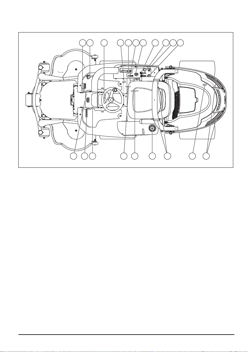
Product overview P 524
1 2 3 54 6 7 8 9 10 11
20 19 17 16 15 14 13 1218
1. Forward drive pedal
2. Rearward drive pedal
3. Light switch
4. Bypass valve to engage or disengage the drive on
the front axle
5. Cutting height lever
6. Lift lever for the cutting deck
7. PTO button, start and stop of the cutting deck
8. Throttle control
9. Choke control
10. Ignition lock
242 - 003 - 3
11. Power outlet 12V
12. Cover lock
13. Bypass valve to engage or disengage the drive on
the rear axle
14. Safety belt
15. Fuel tank cap
16. Seat adjustment
17. Type plate
18. Hour meter
19. Parking brake
20. Lock button for parking brake
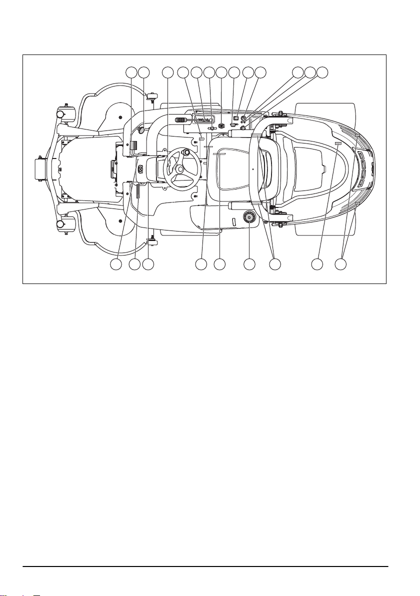
Product overview P 524EFI
1 2 3 54 6 7 8 9 10 11 12 13
22 21 19 18 17 16 15 1420
1. Forward drive pedal
2. Rearward drive pedal
3. Light switch
4. Bypass valve to engage or disengage the drive on
the front axle
5. Cutting height lever
6. Lift lever for the cutting deck
7. PTO button, start and stop of the cutting deck
8. Throttle control
9. On/off switch for the power outlet
10. Ignition lock
11. Warning lamp for low oil pressure
4 242 - 003 -
12. Warning lamp for engine malfunction
13. Power outlet 12V
14. Cover lock
15. Bypass valve to engage or disengage the drive on
the rear axle
16. Safety belt
17. Fuel tank cap
18. Seat adjustment
19. Type plate
20. Hour meter
21. Parking brake
22. Lock button for parking brake
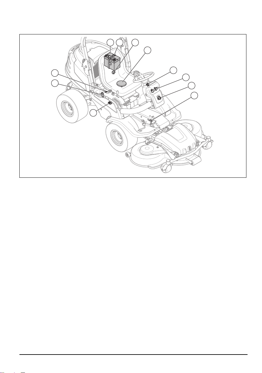
Electrical system overview P 524
1 2 3
4
5
6
7
8
9
10
11
1. Battery
2. Main fuse, 20 A
3. Relay
4. Safety switch for the seat
5. Light switch
6. Headlights
7. Hour meter
8. Microswitch for the hydrostatic transmission
9. Fuse holder
10. Ignition lock
11. Power outlet, 12 V
242 - 003 - 5
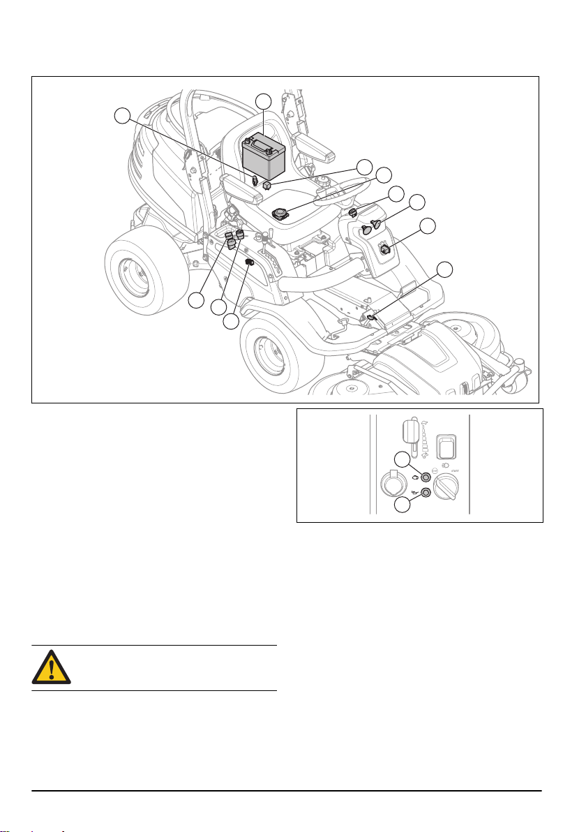
Electrical system overview, P 524EFI
2
1
3
4
5
6
7
8
9
10
11
A
B
1. Main fuse, 20 A
2. Battery
3. Relay
4. Safety switch for the seat
5. Light switch
6. Headlights
7. Hour meter
8. Microswitch for the hydrostatic transmission
9. Fuse holder
10. Ignition lock
11. Power outlet, 12 V
Warning lamps on the control panel, P 524EFI
The engine on model P 524EFI has Electronic Fuel
Injection system. 2 lamps on the control panel show if
there are problems with the engine.
CAUTION: If a lamp on the control panel
comes on, stop the engine and refer to
Troubleshooting on page 40
• A: Engine malfunction
• B: Low oil pressure
.
Hour meter
The hour meter shows how many hours the engine has
run. The time with ignition on but engine off is not
registered. The last digit shows tenths of an hour (6
minutes).
Power outlet
The voltage of the power outlet is 12 V. The power outlet
has a fuse, see
Set the power outlet to on and off with the power switch
found on the control panel.
To replace a fuse on page 28
.
6 242 - 003 -
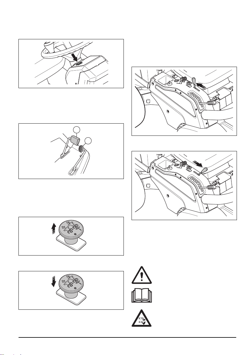
Headlights
1
2
The power switch for the headlights is found on the
steering wheel panel.
Forward and rearward pedals
The speed is gradually adjusted with 2 pedals. The left
pedal (1) is used to move forward, and the right pedal
(2) is used to move rearward. The product brakes when
the pedals are released.
PTO (Power take-off) button
The PTO button starts and stops the cutting deck. The
operator must sit to start the cutting deck.
Pull the PTO button out to engage the drive on the
cutting deck blades.
Lift lever for the cutting deck
The lift lever is used to lift and lower the cutting deck.
The product uses hydraulic pressure to lift the cutting
deck. To operate the lift lever, start the engine and push
down the PTO button.
When you move the lift lever to the transport position,
the cutting deck lifts and the blades stop in
approximately 5 seconds.
When you move the lift lever to the mow position, the
cutting deck lowers and the blades start to rotate.
Cutting deck
The cutting decks for this product are Combi cutting
decks with BioClip. BioClip cuts the grass into fertilizer.
The Combi cutting decks can also be used without
BioClip. Without BioClip the grass is ejected to the rear.
Push the PTO button in to disengage the drive on the
cutting deck blades.
See also
To do a check of the safety circuit on page
12
.
242 - 003 - 7
Symbols on the product
WARNING: Careless or incorrect use can
result in serious injury or death to the
operator or others.
Read the operator's manual carefully and
make sure that you understand the
instructions before use.
Rotating blades. Keep body parts away from
the cover when the engine is on.
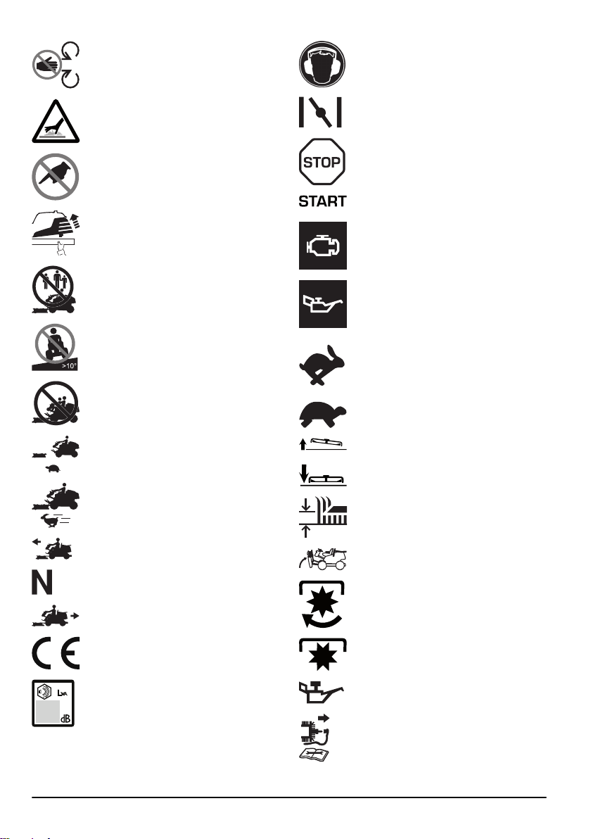
Warning: rotating parts. Keep body parts
away.
Hot surface.
Do not touch.
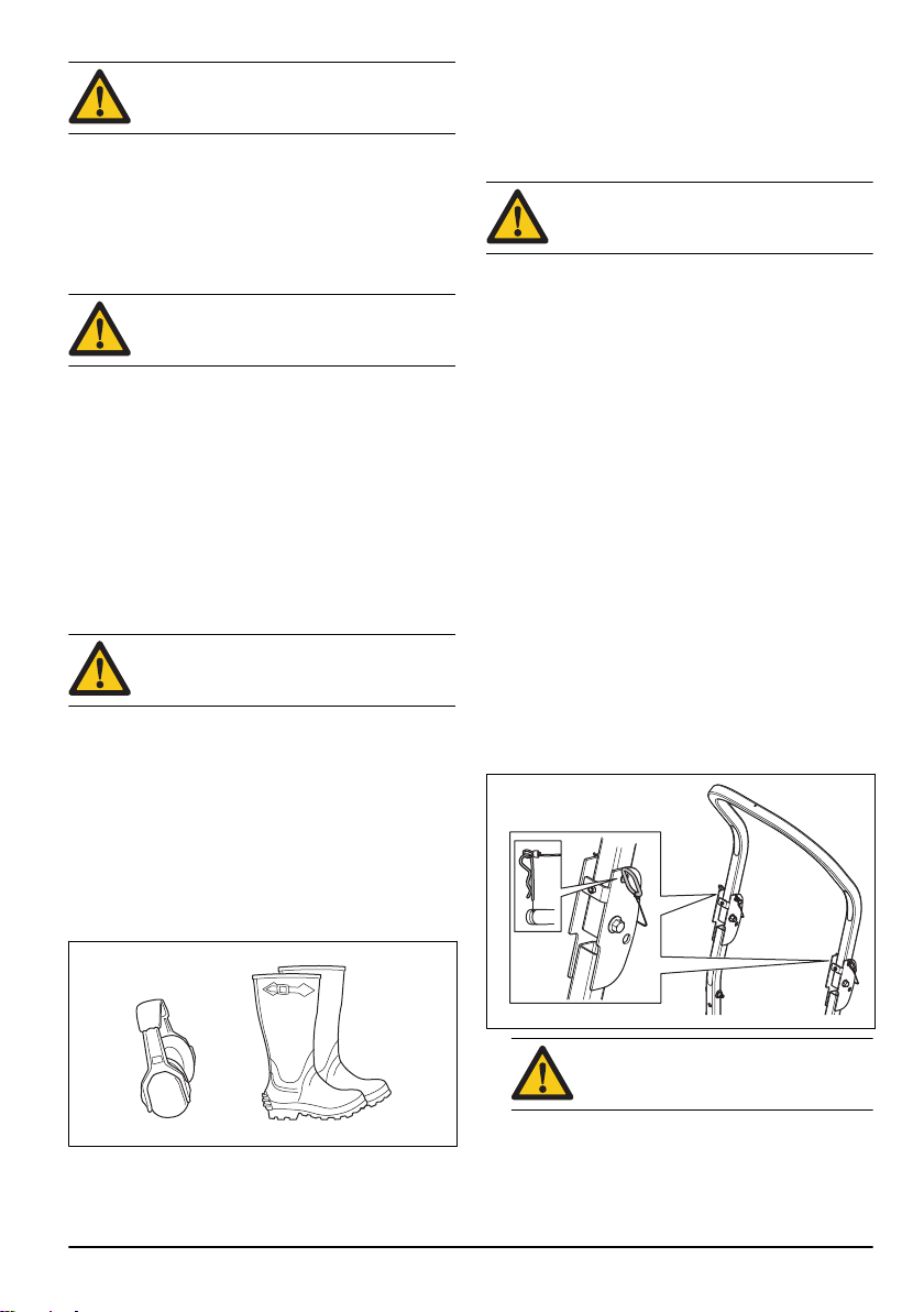
Always use approved hearing protection.
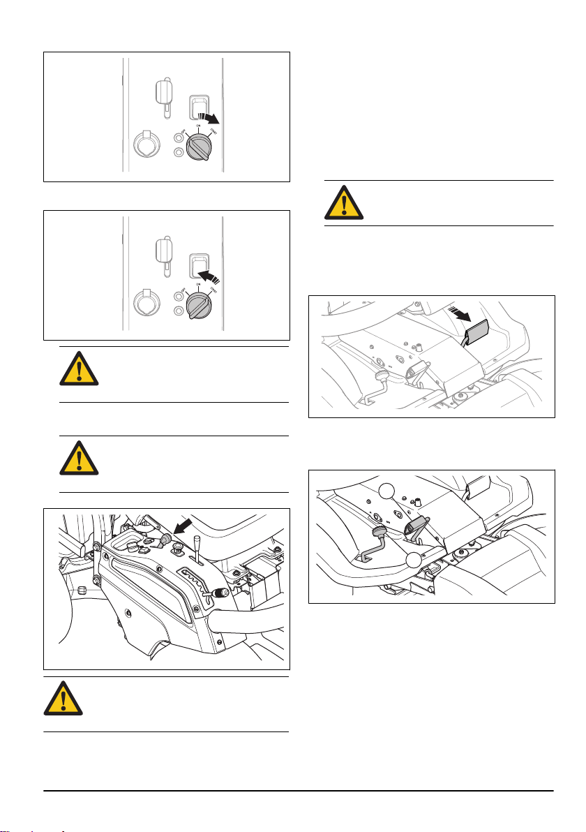
Choke (P 524).
Stop the engine.
Start the engine.
Pull the clip to remove the engine cover.
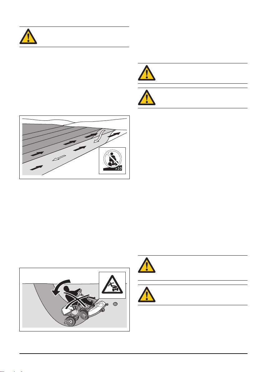
Never use the product if persons, especially
children, or animals, are in the vicinity.
Never cut grass across a slope. Do not cut
grass on ground that slopes more than 10°.
See
To cut grass on slopes on page 13
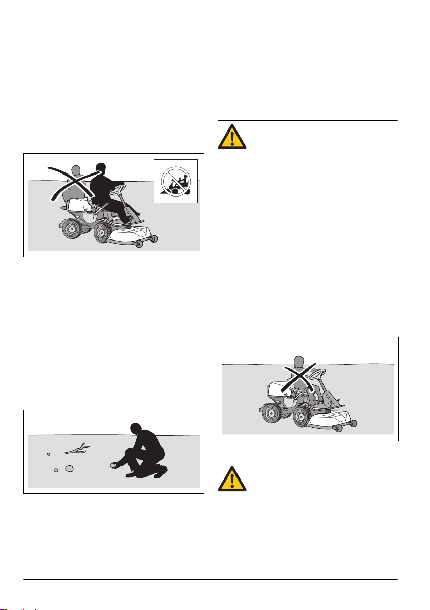
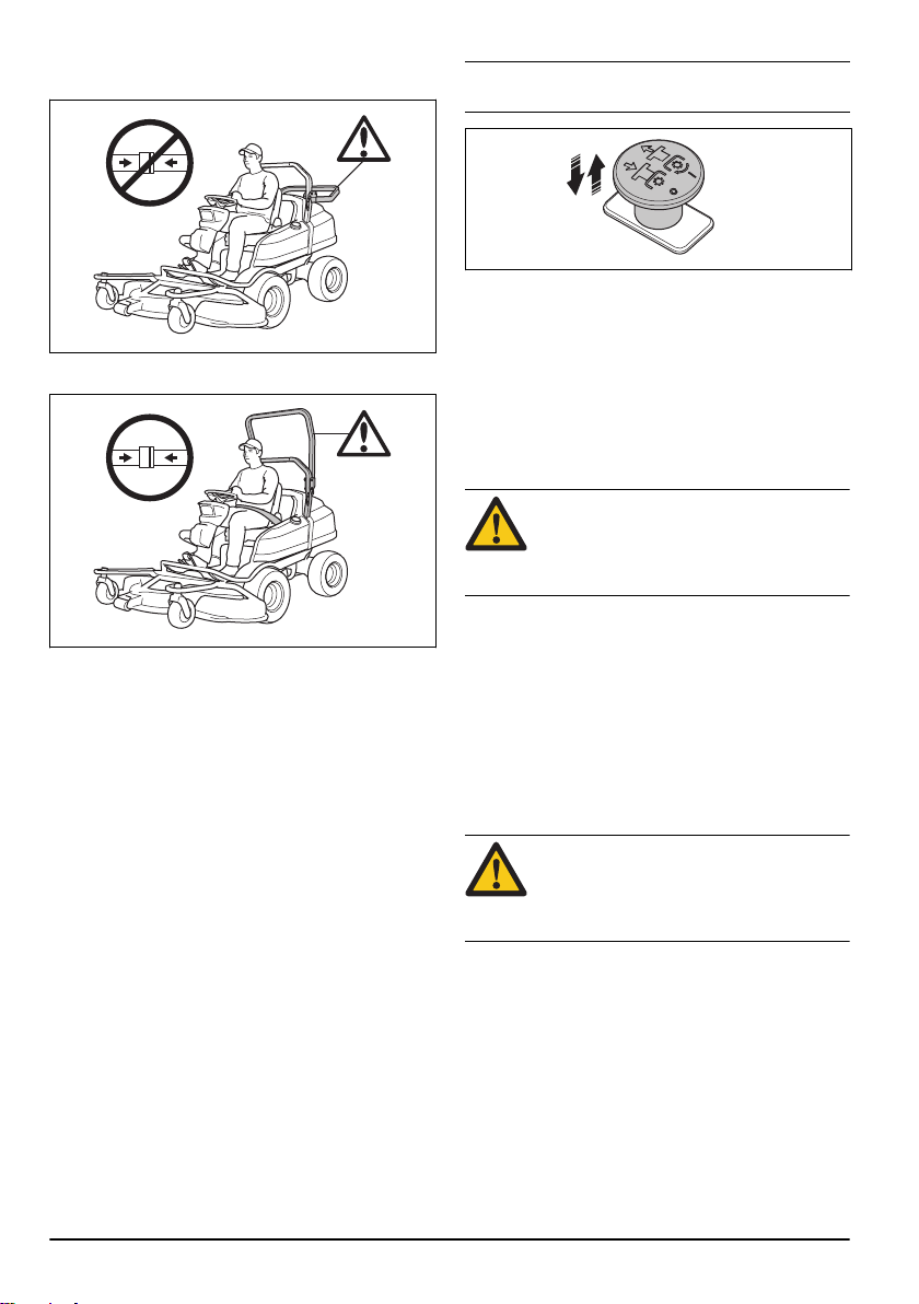
Never carry passengers on the product or
equipment.
Operate the product very slowly if no cutting
deck is attached.
Operate the product at full speed when a
cutting deck is attached.
Move forward.
Neutral gear.
Move rearward.
This product is in accordance with
applicable EC directives.
.
Warning lamp for engine malfunction
(P 524EFI).
Warning lamp for low oil pressure
(P 524EFI).
Engine speed – fast.
Engine speed – slow.
Servicing position for the cutting deck.
Operation position for the cutting deck.
Cutting height.
Servicing position.
The blades are engaged.
The blades are disengaged.
Noise emission to the environment
according to the European Community's
Directive. The product's emission is
specified in the Technical data chapter and
on the label.
8 242 - 003 -
Oil level.
Stop the engine and remove the spark plug
cable before repairs or maintenance.
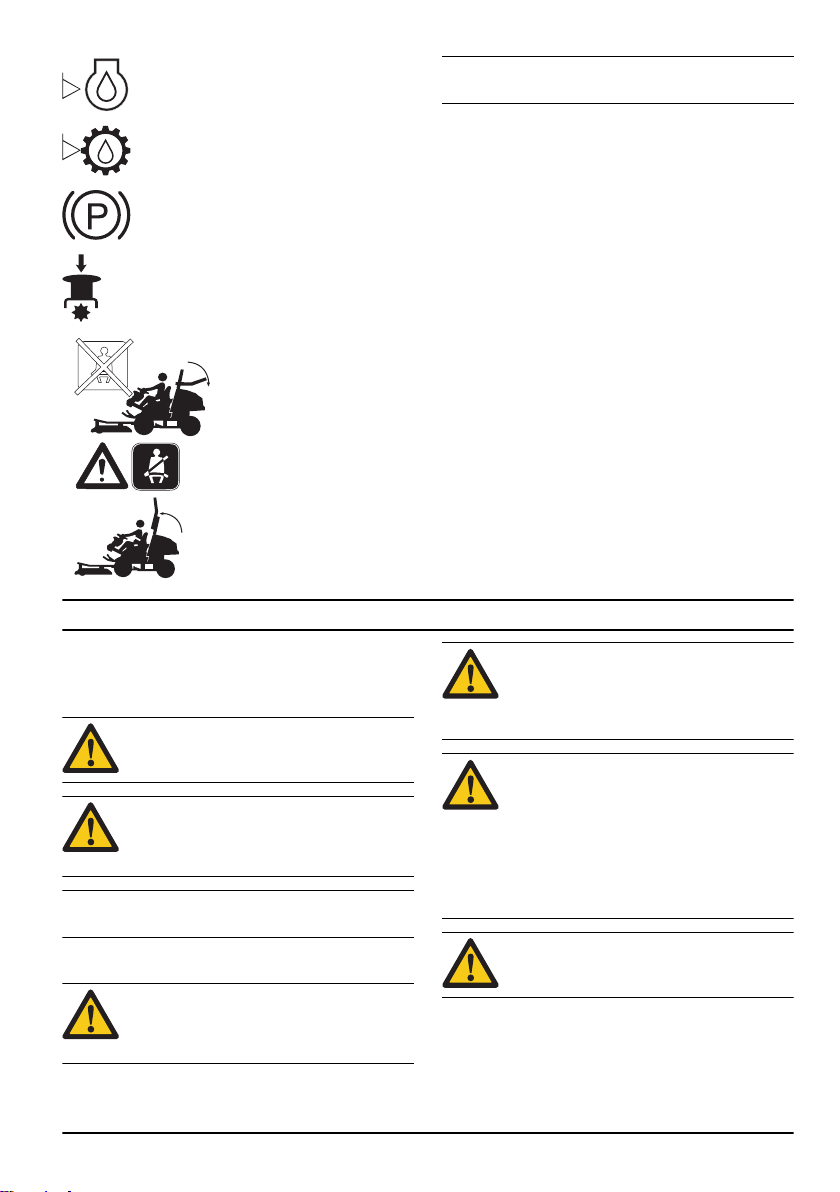
Do a check of the engine oil level.
Do a check of the engine oil level.
Parking brake.
Push in the PTO button.
Do not use the safety belt if the
ROPS is disengaged.
Always use the safety belt when
the ROPS is engaged.
Note: Other symbols/decals on the product refer to
certification requirements for some commercial areas.
Product liability
As referred to in the product liability laws, we are not
liable for damages that our product causes if:
• the product is incorrectly repaired.
• the product is repaired with parts that are not from
the manufacturer or not approved by the
manufacturer.
• the product has an accessory that is not from the
manufacturer or not approved by the manufacturer.
• the product is not repaired at an approved service
center or by an approved authority.
Safety
Safety definitions
Warnings, cautions and notes are used to point out
specially important parts of the manual.
WARNING: Used if there is a risk of injury or
death for the operator or bystanders if the
instructions in the manual are not obeyed.
CAUTION: Used if there is a risk of damage
to the product, other materials or the
adjacent area if the instructions in the
manual are not obeyed.
Note: Used to give more information that is necessary in
a given situation.
General safety instructions
WARNING: This product can cut off hands
and feet and throw objects. Serious injury or
death may occur if you do not obey the
safety instructions.
242 - 003 - 9
• Always be careful and use your common sense.
WARNING: Do not continue to use a product
with damaged cutting equipment. Damaged
cutting equipment can throw objects and
cause serious injury or death. Replace
damaged blades immediately.
WARNING: This product produces an
electromagnetic field during operation. This
field may under some circumstances
interfere with active or passive medical
implants. To reduce the risk of serious or
fatal injury we recommend persons with
medical implants to consult their physician
and the medical implant manufacturer
before operating this product.
WARNING: Read the warning instructions
that follow before you use the product.
Avoid all situations which you consider to be beyond
your capability. If you feel uncertainty about the
operating procedures after you read the operator's
manual, consult an expert before you continue.
• Read and understand the operator's manual and the
instructions on the product carefully before you start
the product.
• Learn how to use the product and its controls safely
and learn how to stop the product quickly.
• Learn to recognize the safety decals.
• Keep the product clean to make sure that you can
clearly read signs and stickers.
• Keep in mind that the operator will be held
responsible for accidents that involve other persons
or their property.
• Do not transport passengers. The product must only
be used by one person.
• Do not let the product stay unsupervised with the
engine on. Always stop the blades, apply the parking
brake, stop the engine and remove the ignition key
before you let the product stay unsupervised.
• Only use the product in daylight or in other well-lit
conditions. Keep the product at a safe distance from
holes or other irregularities in the ground. Look out
for other possible risks.
• Do not use the product in bad weather, for example
in fog, in rain, moist or in wet locations, strong winds,
intense cold, risk of lightning, etc.
• Find and mark stones and other fixed objects to
prevent collision.
• Clear the area of objects such as stones, toys, wires,
etc. that may become caught in the blades and be
thrown out.
• Keep an eye on the traffic when you mow near a
road or move across a road.
• Do not use the product if you are fatigued, while
under the influence of alcohol or drugs, medicine or
anything that can have a negative effect on your
vision, alertness, coordination or judgement.
• Always park the product on a level surface with the
engine stopped.
Safety instructions regarding children
WARNING: Read the warning instructions
that follow before you use the product.
• Serious accidents can occur if you are not on your
guard for children in the vicinity of the product.
Children can be attracted to the product and to
mowing. It is very possible that children do not stay
where you last saw them.
• Keep children away from the area to be mowed.
Make sure that an adult is responsible for the
children.
• Keep an eye out and stop the product if children
enter the work area. Be very careful near corners,
bushes, trees or other objects that prevents a clear
view.
• Before and while you move the product in reverse,
look behind you and look down to make sure there
are no small children in the vicinity of the product.
• Do not let children ride along. They can fall off and
get seriously injured or prevent safe maneuvering of
the product.
• Do not let children operate the product.
Safety instructions for operation
WARNING:
exhaust system during or directly after
operation. The engine and the exhaust
• Do not let children or other persons not approved for
operation of the product to use or do servicing on it.
Local laws may regulate the age of the user.
• Make sure that nobody else is in the vicinity of the
product when you start the engine, engage the drive
or start to move the product.
10 242 - 003 -
system become very hot during operation.
Risk of burn injuries, fire and damage to
property or adjacent areas. When you
operate the product, keep away from bushes
and other objects.
Do not touch the engine or
WARNING: Read the warning instructions
that follow before you use the product.
• Always look down and behind you before and while
you move in reverse. Look out for large and small
obstacles.
• Decrease the speed before you turn around a
corner.
• Stop the blades when you move across areas that
you do not cut.
CAUTION: Read the caution instructions
that follow before you use the product.
• Before you operate the product, clear the cold air
intake of the engine from grass and dirt. If the cold
air intake is blocked, there is a risk of engine
damage.
• Move around stones and other larger objects
carefully and make sure that the blades do not hit
the objects.
• Do not operate the product across objects. Stop and
examine the product and cutting deck if you operate
the product across or into an object. If it is
necessary, make repairs before you restart.
Personal protective equipment
WARNING: Read the warning instructions
that follow before you use the product.
• Use approved personal protective equipment when
you use the product. Personal protective equipment
cannot fully prevent injury but it decreases the
degree of injury if an accident does occur. Let your
dealer help you select the right equipment.
• Always wear approved hearing protection. Long term
exposure to noise can result in permanent hearing
impairment.
• Always wear protective shoes or protective boots.
Steel toes are recommended. Do not use the
product barefoot.
• Do not wear loose-fitting clothing, jewelry or other
items that can get caught in moving parts.
• Keep first aid equipment and fire extinguisher close
at hand.
Safety devices on the product
WARNING: Read the warning instructions
that follow before you use the product.
• Do not use a product with defective safety devices.
Do a check of the safety devices regularly. If the
safety devices are defective, speak to your
Husqvarna service agent.
• Do not make modifications on safety devices. Do not
use the product if protective plates, protective
covers, safety switches or other protective devices
are not attached or are defective.
Roll Over Protection Structure (ROPS)
ROPS is a protective frame that decreases the risk of
injury if the product overturns. Use the ROPS and the
safety belt when you operate the product on slopes.
Safety belt
The safety belt prevents injury if accidents occur or the
product overturns. Use the safety belt only when the
ROPS is engaged. Make sure that the seat belt is
correctly attached and not damaged.
To engage and disengage the Roll Over Protection Structure (ROPS)
• Remove the 2 pins that hold the ROPS and fold it
rearwards to disengage. Engage the ROPS in the
opposite sequence.
WARNING:
instructions for the ROPS and the safety
belt.
• Wear gloves when necessary, for example when you
attach, examine or clean the cutting equipment.
242 - 003 - 11
Obey the following
• Do not use the safety belt if the ROPS is
disengaged.
• Always use the safety belt when the ROPS is
engaged.
Note: If the safety circuit stops the blades, push the PTO
button in and pull it out again to start the blades.
To do a check of the speed limiter
• Release the forward pedal to brake.
• For more brake power, press the reverse pedal.
• Make sure that the forward and reverse pedals are
not blocked and can be operated freely.
• Make sure that the product brakes when the forward
pedal is released.
Parking brake
WARNING: If the parking brake does not
work, the product can start to move and
cause injury or damage. Make sure that the
parking brake is regularly examined and
adjusted.
See
To do a check of the parking brake on page 26
.
• Make sure that the ROPS is correctly attached and
not damaged.
To do a check of the ignition lock
• Start and stop the engine to do a check of the
ignition lock. See
17
and
• Make sure that the engine starts when you turn the
• Make sure that the engine stops immediately when
To do a check of the safety circuit
The safety circuit makes sure that the engine only starts
in some conditions. The drive on the blades must be
disengaged and the parking brake must be applied.
The safety circuit stops the blades if the operator does
not stay in the seat when the cutting deck is lowered.
• Do a check of the safety circuit daily.
• Try to start the engine with one of the conditions
• Engage the drive on the blades and lift from the seat.
12
To stop the engine on page 20
ignition key to START.
you turn the ignition key to STOP.
above not obeyed. Change the conditions and try
again. If the safety circuit works, the engine does not
start.
If the safety circuit works, the blades in the cutting
deck stop.
To start the engine, P 524 on page
.
Muffler
The muffler keeps the noise levels to a minimum and
sends the exhaust fumes away from the operator.
Do not use the product if the muffler is missing or
defective. A defective muffler increases the noise level
and the risk of fire.
Examine the muffler regularly to make sure that it is
attached correctly and not damaged.
CAUTION:
during and after use and when the engine
operates at idle speed. Be careful near
flammable materials and/or fumes to prevent
fire.
Protective covers
Missing or damaged protective covers increase the risk
of injury on moving parts and hot surfaces. Do a check
of the protective covers before you operate the product.
Make sure that the protective covers are correctly
attached and do not have cracks or other damages.
Replace damaged covers.
The muffler becomes very hot
242 - 003 -
To cut grass on slopes
WARNING: Read the warning instructions
that follow before you use the product.
• To cut grass on slopes increases the risk that you
can not control the product and that it overturns. This
can cause injury or death. It is necessary to cut the
grass carefully on all slopes. If you cannot reverse
up a slope or if you do not feel safe, do not cut it.
• Remove stones, branches and other obstacles.
• Cut up and down the slope, not from side to side.
• Do not move down a slope with the cutting deck
lifted.
• Do not operate the product on ground that slopes
more than 10°.
• Do not start or stop on a slope.
• Move smoothly and slowly on slopes.
• Do not make sudden changes in speed or direction.
• Do not turn more than necessary. Turn slowly and
gradually when you move down a slope. Move at low
speed. Turn the wheel carefully.
• Look out for and do not move across furrows, holes
and bumps. There is a higher risk that the product
overturns on ground that is not flat. Long grass can
hide obstacles.
• Do not cut grass near edges, ditches or banks. The
product can suddenly overturn if a wheel moves
across the edge of a steep slope or a ditch, or if an
edge gives way. If the product falls into water, there
is a risk of drowning.
• Do not put your foot on the ground to try to make the
product more stable.
• Move very carefully if an accessory or other object is
attached that can make the product less stable.
• To increase stability, attach counterweights. Speak
to your dealer for more information.
Fuel safety
WARNING: Be careful with fuel. It is very
flammable, and can cause injury and
damage to property.
WARNING: Read the warning instructions
that follow before you use the product.
• Do not fill the fuel tank indoors.
• Gasoline and gasoline fumes are poisonous and
very flammable. Be careful with gasoline to prevent
injury or fire.
• Do not remove the fuel tank cap or fill the fuel tank
when the engine is on.
• Let the engine become cool before you refuel.
• Do not smoke when you fill fuel.
• Do not fill fuel near sparks or naked flames.
• If there are leaks in the fuel system, do not start the
engine until the leaks are repaired.
• Do not fill above recommended fuel level. The heat
from the engine and the sun makes the fuel expand
and the fuel overflows if the tank is filled too much.
• Do not fill too much. If you spill fuel on the product,
clean up the spill and wait until it is dry before you
start the engine. If you spill on your clothing, change
it.
• Store fuel in approved containers only.
• Store the product and fuel in such a way that there is
no risk that fuel leaks or fumes can cause damage.
• Drain off the fuel in an approved container outdoors
and away from naked flames.
Battery safety
WARNING:
an explosion and cause injury. If the battery
has a deformation or is damaged, speak to
an approved Husqvarna service agent.
A damaged battery can cause
• Do not mow wet grass. It is slippery, and tires can
lose their grip so that the product skids.
242 - 003 -
WARNING: Read the warning instructions
that follow before you use the product.
• Use protective glasses when you are near batteries.
• Do not wear watches, jewelry or other metal objects
near the battery.
• Keep the battery out of reach for children.
• Charge the battery in a space with good airflow.
13
• Keep flammable materials at a minimum clearance
of 1 m when you charge the battery.
• Discard replaced batteries. See
43
.
• Explosive gases can come from the battery. Do not
smoke near the battery. Keep the battery away from
open flames and sparks.
Disposal on page
Safety instructions for maintenance
WARNING: The product is heavy and can
cause injury or damage to property or the
adjacent area. Do not do maintenance on
the engine or the cutting deck without these
conditions:
• The engine is off.
• The product is parked on a level surface.
• The parking brake is applied.
• The ignition key is removed.
• The cutting deck is disengaged.
• The ignition cables are removed from the
plugs.
WARNING: The exhaust fumes from the
engine contain carbon monoxide, an
odourless, poisonous and very dangerous
gas. Do not run the product in closed spaces
or spaces with not sufficient air flow.
WARNING: Read the warning instructions
that follow before you use the product.
• For best performance and safety, do maintenance
on the product regularly as given in the maintenance
schedule. See
• Electrical shocks can cause injuries. Do not touch
the cables when the engine is on. Do not do a
function test on the ignition system with your fingers.
• Do not start the engine if the protective covers are
removed. There is a high risk of injury caused by
moving or hot parts.
• Let the product become cool before you do
maintenance near the engine.
• The blades are sharp and can cause cuts. Wind
protection around the blades or use protective
gloves when you do work on the blades.
• Always put the cutting deck in servicing position to
clean it. Do not park the product near the edge of a
ditch or slope to get access to the cutting deck.
• Do not turn over the engine if the spark plug or
ignition cable is removed.
• Make sure that all nuts and bolts are tightened
correctly and that the equipment is in good condition.
• Do not change the adjustment of governors. If the
engine speed is too high, the product components
can become damaged. See
44
for highest permitted engine speed.
• The product is approved only with the equipment
supplied or recommended by the manufacturer.
Maintenance schedule on page 21
CAUTION: Read the caution instructions
that follow before you use the product.
Technical data on page
.
Assembly
Introduction
WARNING: The drive belt tension spring can
break and cause injury. Wear protective
glasses when you attach or remove the
cutting deck.
Read the assembly instructions in the owner's manual
carefully. A label on the inner side of the front cover on
the product, also shows how to attach and remove the
cutting deck.
To attach the cutting deck
1. Park the product on level ground.
2. Apply the parking brake.
3. Set the cutting height lever in the servicing position.
14 242 - 003 -
4. Push the equipment frame down. Lift the equipment
frame lock to vertical position.
WARNING: The lock mechanism can
cause injury to fingers if you do not
operate it carefully. Hold the front edge
of the cutting deck with two hands when
you continue to the next step.
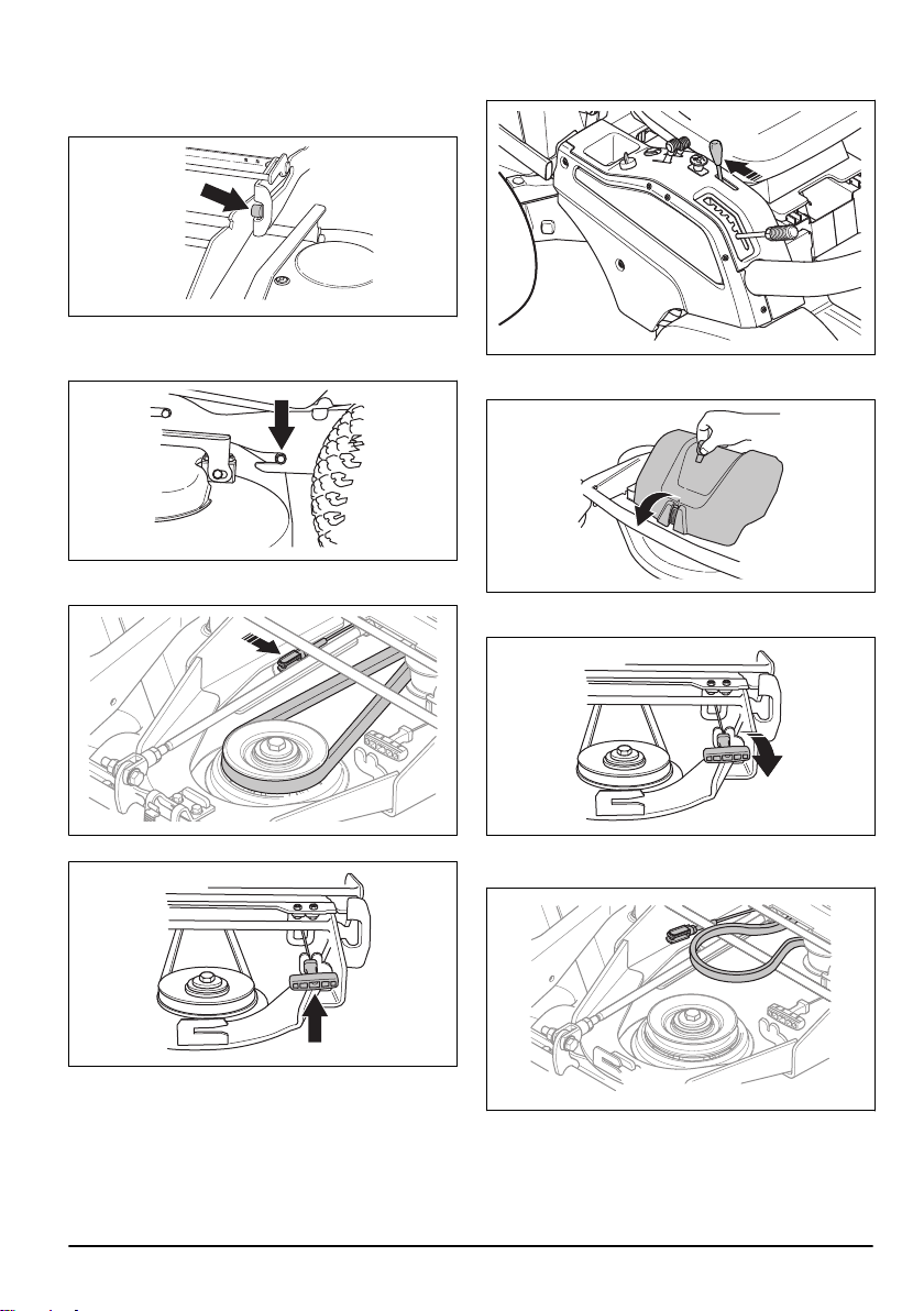
5. Push the cutting deck into the equipment frame.
Make sure that the front guide plugs go in the
grooves on the equipment frame. The equipment
frame lock releases automatically.
6. Push the cutting deck in until the rear guide plugs
touch the bottom of the grooves on the equipment
frame.
7. Put the drive belt around the drive wheel for the
cutting deck and attach the cutting height cable.
4. Pull the lift lever for the cutting deck rearward to its
locked position to lift up the cutting deck.
5. Release the clip on the front cover with the tool
attached to the ignition key, and remove the cover.
6. Pull the spring handle out from the spring holder to
loosen the drive belt tension.
8. Put the spring handle in the spring holder.
9. Attach the front cover.
To remove the cutting deck
1. Park the product on level ground.
2. Apply the parking brake.
3. Set the cutting height lever in the servicing position.
242 - 003 -
7. Disconnect the cutting height cable.
8. Remove the drive belt and put it in the belt holder.
15
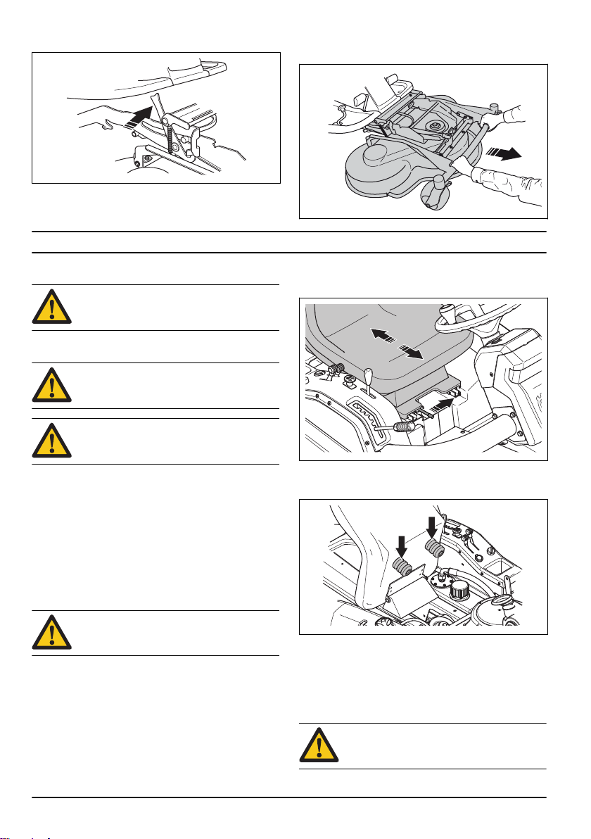
9. Open the equipment frame lock. 10. Hold the front edge of the cutting deck with 2 hands
and pull it out.
Operation
Introduction
WARNING: Before you operate the product,
you must read and understand the safety
chapter.
To fill fuel
WARNING: Gasoline is very flammable. Be
careful and refuel outdoors (see
on page 13
WARNING: Do not use the fuel tank as a
support area.
The engine runs on unleaded gasoline with a minimum
octane rating of 95 (not mixed with oil). We recommend
biodegradable alkylate gasoline (max. methanol 5%,
max. ethanol 10%, max. MTBE 15%).
Do a check of the fuel level before each use and refuel if
necessary.
You can clearly see the fuel level in the fuel tank. Do not
fill too much. Keep a minimum space of 2.5 cm.
).
Fuel safety
To adjust the seat
• To adjust the seat forward and rearward, push the
lever below the front edge of the seat to the left.
Move the seat to the required position.
• To adjust the seat springs, move the rubber stops
below the seat as given in the illustration. Put the 2
stops in the front, middle or rear.
WARNING: Do not adjust the seat during
operation of the product.
The seat can be tilted forward. It can also be adjusted
forward and rearward.
16 242 - 003 -
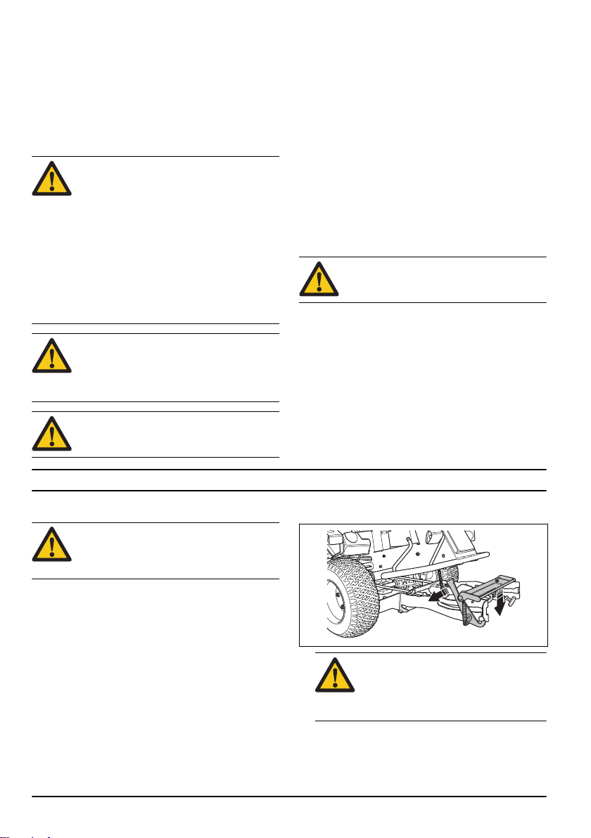
To release and apply the hydraulic pressure
To move the product with the engine off, you must
release the hydraulic pressure. The hydraulic pressure
is released and applied with a bypass valve.
CAUTION:
you operate the product. If they are open,
the transmission can become damaged.
Close the 2 bypass valves before
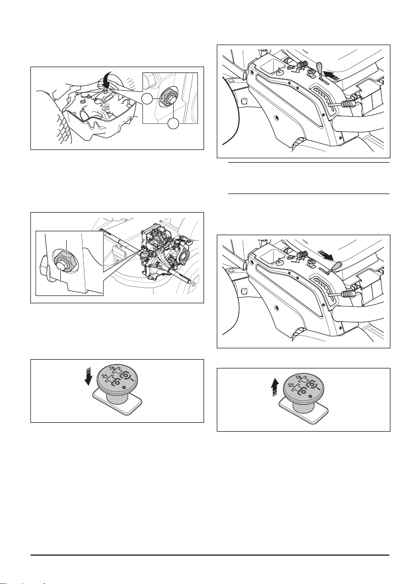
Rear axle
A
B
A
B
• To release the hydraulic pressure, open the locknut
(A) ¼–½ turn counterclockwise and then the valve
nut (B) 2 turns counterclockwise.
• To apply the hydraulic pressure, close the valve nut
(B) fully and then tighten the locknut (A).
Front axle
• To release the hydraulic pressure, open the locknut
(A) ¼–½ turn counterclockwise and then the valve
nut (B) 2 turns counterclockwise.
• To apply the hydraulic pressure, close the valve nut
(B) fully and then tighten the locknut (A).
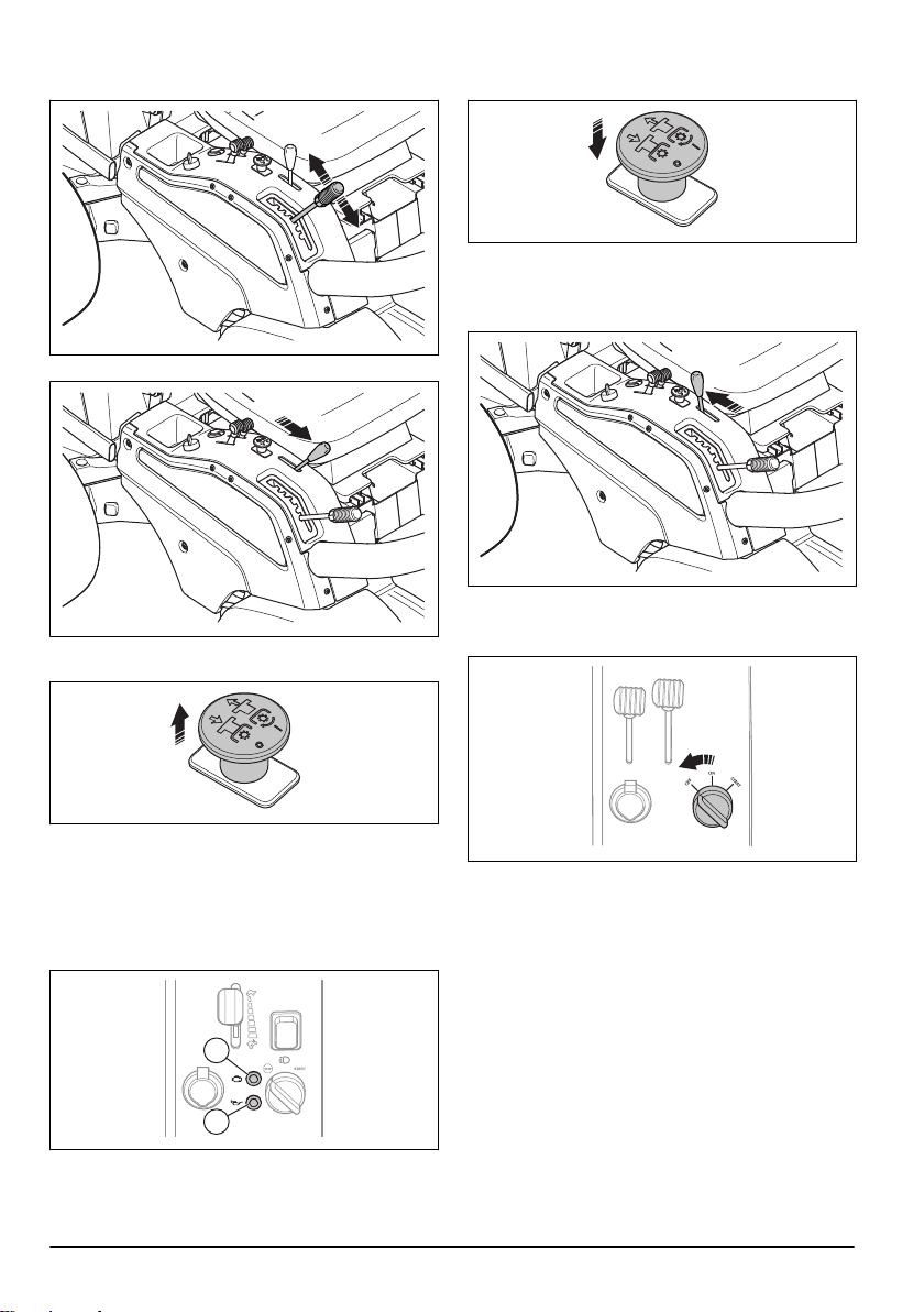
To lift the cutting deck
1. Push the PTO button in to disengage the drive on
the cutting deck.
2. Pull the lift lever rearward to lift the cutting deck to
transport position.
Note: You can lift the cutting deck a small distance
with the drive on the blades engaged. Use this
function for very long grass or rough surfaces.
To lower the cutting deck to operation position
1. Move the lift lever forward to lower the cutting deck.
2. Pull the PTO button out to engage the drive on the
cutting deck blades.
242 - 003 -
To start the engine, P 524
1. Make sure that the bypass valves are closed. Refer
to
To release and apply the hydraulic pressure on
page 16
.
2. Apply the parking brake.
17
3. Push in the PTO button to disengage the drive on
the cutting deck.
4. Move the throttle control to the middle position.
5. If the engine is cold, move the choke control fully
rearward.
CAUTION:
more than 5 seconds at a time. If the
engine does not start, wait 15 seconds
before you try again.
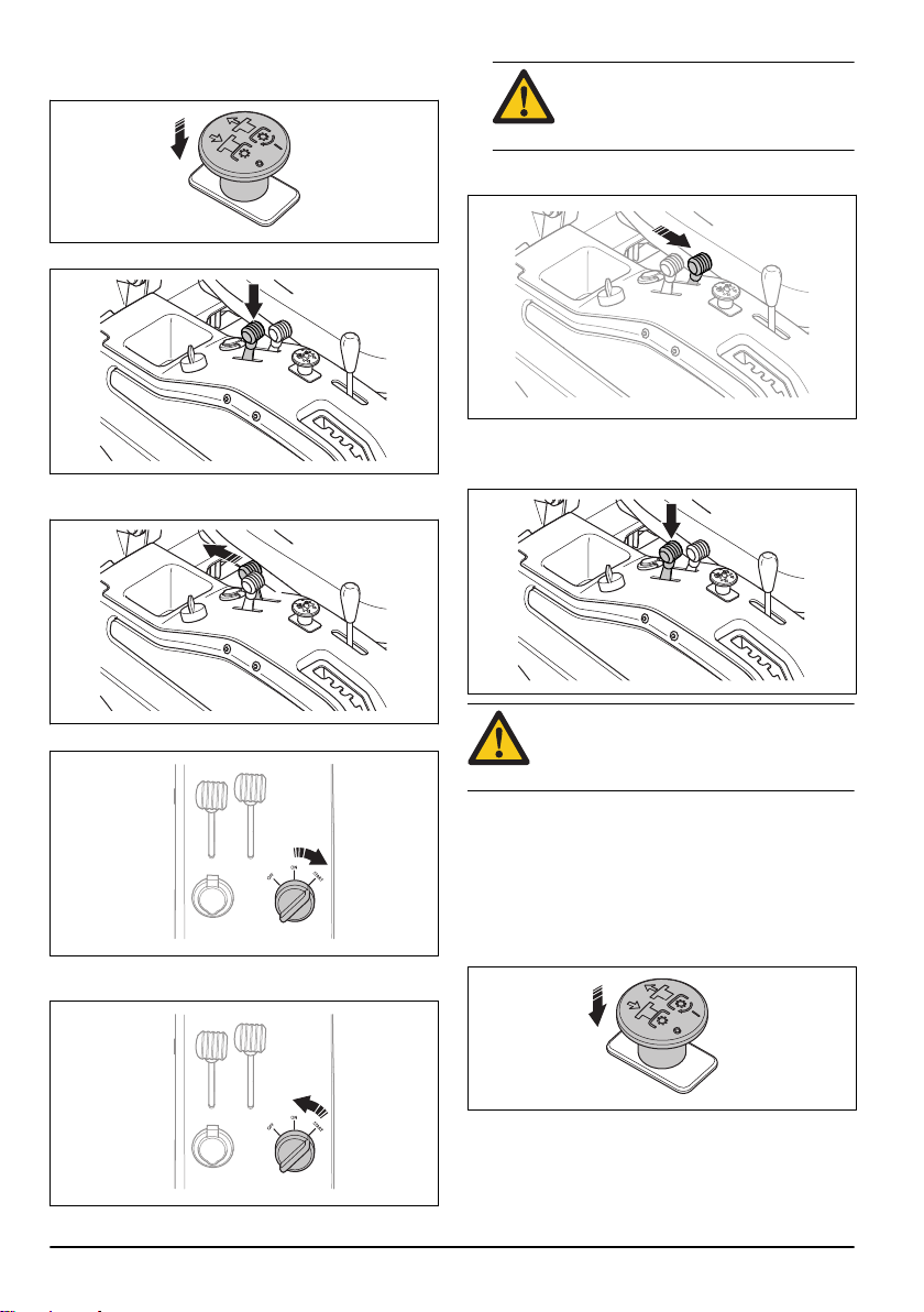
8. Push the choke control gradually forward to the end
position.
9. Let the engine run at half throttle for 3-5 minutes
before you apply a heavy load.
10. Push the throttle control to full throttle position.
Do not run the starter for
6. Turn the ignition key to the start position.
7. When the engine starts, immediately release the
ignition key to neutral position.
18
CAUTION: To engage the blades when the
engine is at full speed causes strain on the
drive belts. Do not apply full throttle until the
cutting deck is lowered to the mow position.
To start the engine, P 524EFI
1. Make sure that the bypass valves are closed. Refer
to
To release and apply the hydraulic pressure on
page 16
.
2. Apply the parking brake.
3. Push in the PTO button to disengage the drive on
the cutting deck.
242 - 003 -
4. Turn the ignition key to the start position.
A
B
5. When the engine starts, immediately release the
ignition key to neutral position.
CAUTION: Do not run the starter for
more than 5 seconds at a time. If the
engine does not start, wait 15 seconds
before you try again.
6. Let the engine run at half throttle for 3-5 minutes
before you apply a heavy load.
CAUTION:
pressure comes on, stop the engine
immediately and refer to
on page 40
7. Push the throttle control to full throttle position.
If the warning lamp for oil
Troubleshooting
.
To start and operate the product in cold weather
• If the engine does not start easily in cold weather,
turn the ignition key many times until the engine
starts. For P 524, make sure that the choke control is
moved fully rearward.
• At temperatures lower than 0°C, let the product
become warm before you apply a heavy load.
Operate the product but do not engage the
equipment for a minimum of 10 minutes.
CAUTION: If the product is not warm
when you start to operate it, the
transmission can become damaged.
To operate the product
1. Start the engine.
2. Press the parking brake pedal down and then
release it to disengage the parking brake.
3. Carefully press down one of the speed pedals. The
speed increases the more the pedal is pressed
down. Use pedal (A) to move forward, and pedal (B)
to reverse.
242 - 003 -
4. Release the pedal to brake. To brake harder, press
down the other speed pedal.
CAUTION: To engage the blades when the
engine is at full speed causes strain on the
drive belts. Do not apply full throttle until the
cutting deck is lowered to the mow position.
19
5. Select the cutting height (1–6) with the cutting height
A
B
lever.
6. Move the lift lever forward to lower the cutting deck.
7. Pull the PTO button out to engage the drive on the
cutting deck blades.
2. Push the PTO button in to disengage the drive on
the cutting deck blades.
3. Operate the engine at idle speed for 1 minute to
decrease the engine temperature.
4. Pull the lift lever for the cutting deck rearward to lift
up the cutting deck.
5. Move the throttle control forward to the MIN.
position.
6. Turn the ignition key to the STOP position.
Reduced power mode, P 524EFI
If the engine malfunctions, the engine speed
automatically decreases to low idle speed and the
warning light for engine malfunction (A) comes on. See
Troubleshooting on page 40
malfunction.
for possible causes of the
To stop the engine
1. Release the speed pedals.
20
7. When the product stops, apply the parking brake.
To apply and release the parking brake
1. Press the parking brake pedal down (A).
242 - 003 -
2. Press and hold the lock button (B).
B
A
4. To release the parking brake, press the parking
brake pedal again.
To get a good cutting result
• Do not cut a wet lawn. Wet grass can give a bad
cutting result.
• Start with a high cutting height and decrease it
gradually.
• Cut with blades that rotate at high speed (highest
3. Keep the button pressed and release the parking
brake pedal.
permitted engine speed, see
44
). Move the product forward at low speed. If the
grass is not too high and thick, you can get a good
cutting result also at a higher speed.
• To get the best cutting result, cut the grass
frequently and use the BioClip function.
Technical data on page
Maintenance
Introduction
WARNING: Before you do any maintenance
work you must read and understand the
safety chapter.
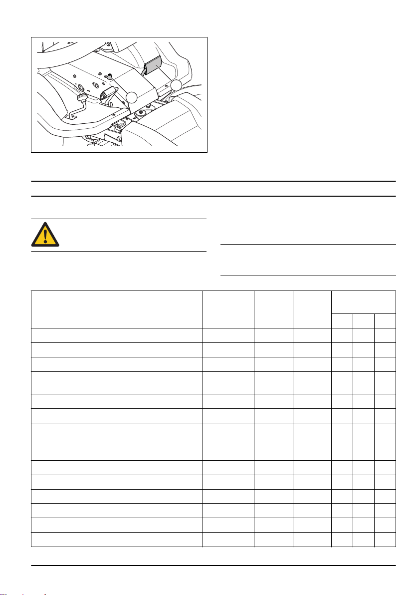
Maintenance schedule
* = General maintenance done by the operator. The
instructions are not given in this operator's manual.
Maintenance Daily, before
Make sure that nuts and screws are tightened *
Make sure that there are no fuel or oil leaks *
Clean as given in
Clean the inner surface of the cutting deck, around
the blades
Clean around the engine and the muffler X
Clean the hydraulic oil cooler X
Make sure that the cold air intake of the engine is not
blocked
Make sure that the safety devices are not defective X
Examine and do a test of the brakes *
Do a check of the engine oil level X
Do a check of the oil level in the transmission X
Examine the cutting deck for damages X
Examine the blades in the cutting deck X
Do a check of the parking brake X
To clean the product on page 23
X = The instructions are given in this operator's manual.
O = The instructions are not given in this operator's
manual. Let an approved service agent do the
maintenance.
Note: If more than one time interval is identified in the
table, the shortest time interval is for the first
maintenance only.
operation (10
hour intervals)
X
X
X
After the
first 25
hours
Weekly
(40 hour
intervals)
Maintenance interval in hours
100 200 400
242 - 003 - 21

Maintenance Daily, before
operation (10
hour intervals)
Clean the inner surfaces of the frame tunnel *
Lubricate the seat slides X
Lubricate the articulated bearing X X
Lubricate according to the lubrication overview X X X
Clean the cutting deck, below the belt covers and below the cutting deck
Make sure that the tire pressure is correct X X
Replace the engine oil X X
Replace the oil filter X O
Clean the air filter X X
After the cleaning procedure, do a visual inspection of
the PTO belt tension
After the cleaning procedure, do a visual inspection of
the pump belt tension
After the cleaning procedure, do a visual inspection of
the cutting deck bolts for the belt pulleys and the
blades
After the cleaning procedure, do a visual inspection of
the hydraulic hoses and couplings to make sure that
they are clean and not damaged
After the cleaning procedure, do a visual inspection of
the joint bearing in the articulation
After the cleaning procedure, do a visual inspection of
all pulleys
Replace the inner air filter X X
Replace the air filter cartridge X
Replace the fuel filter X X
Do a check of the headlights, replace broken lamps X X X
Do a check of the parallelism of the cutting deck X X
Lubricate the belt adjuster X O O
Lubricate the joints and bearings on the cutting deck X
Lubricate the pedal system in the frame tunnel X
Lubricate the chains in the frame tunnel X
Lubricate the parking brake cable X
Lubricate the throttle cable (P 524 only) X
Lubricate the choke cable (P 524 only) X
Lubricate the cable for the hydrostatic transmission X
After the
first 25
hours
*
Weekly
(40 hour
intervals)
* * *
* * *
Maintenance interval in hours
100 200 400
X
*
*
*
22 242 - 003 -
Maintenance Daily, before
operation (10
hour intervals)
Replace the drive belt for the cutting deck X
Replace the V-belt on the cutting deck X
Examine the muffler and heat deflector O O
Examine the spark plug for damages and make sure
that the electrode gap is correct
Replace the spark plug X
Do a check of and adjust the throttle cable (P 524 only)
Do a check of and adjust the choke cable (P 524 only)
Clean the cooling fins on the engine and the transmission
Clean the engine and the transmission O O
Do a check of/adjust front and rear wheel speed O
Do a check of the fuel hose. Replace it if necessary O
Replace the oil in the transmission O O
After the
first 25
hours
Weekly
(40 hour
intervals)
O O
Maintenance interval in hours
100 200 400
X
O
O
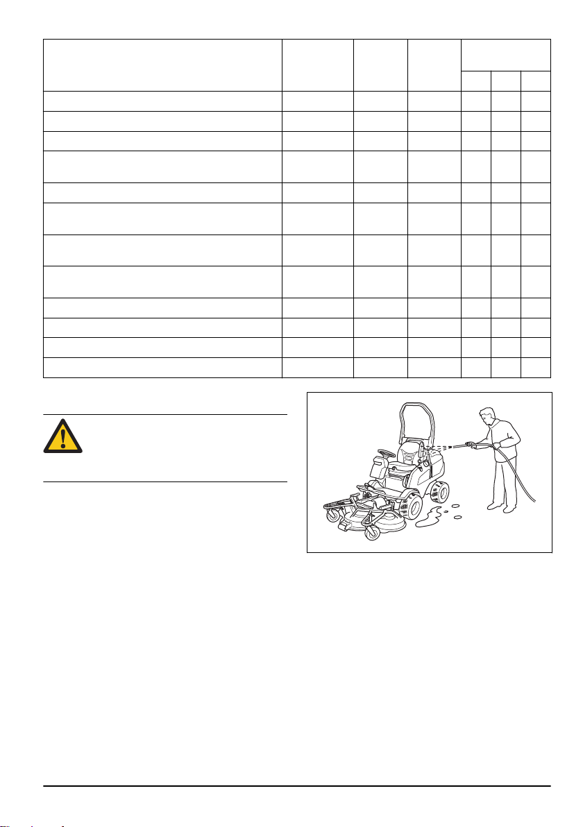
To clean the product
CAUTION: Do not use a high-pressure
washer or a steam cleaner. Water can go
into bearings and electrical connections and
cause corrosion which causes damage to
the product.
Clean the product immediately after use.
• Do not clean hot surfaces such as the engine,
muffler and exhaust system. Wait until the surfaces
are cool, then remove the grass or dirt.
• Before you clean with water, clean with a brush.
Remove grass cuttings and dirt on and around the
transmission, the transmission air intake, and the
engine.
• Use running water from a hose to clean the product.
Do not use high pressure.
• Do not point the water at electrical components or
bearings. Detergent usually increases the damage.
• To clean the cutting deck, put it in the servicing
position and hose it down with water.
• When the product is clean, start the cutting deck for
a short period to blow off remaining water.
• Examine all lubrication points and lubricate if it is
necessary. Always lubricate the bearings after you
clean the product.
242 - 003 - 23
To clean the engine and the muffler
Keep the engine and muffler free from grass cuttings
and dirt. Grass cuttings soaked in fuel or oil on the
engine can increase the fire risk and the risk that the
engine becomes too hot. Let the engine cool before it is
cleaned. Clean with water and a brush.
Grass cuttings around the muffler dry quickly and are a
fire risk. Use a brush or remove the grass cuttings with
water when the muffler is cold.
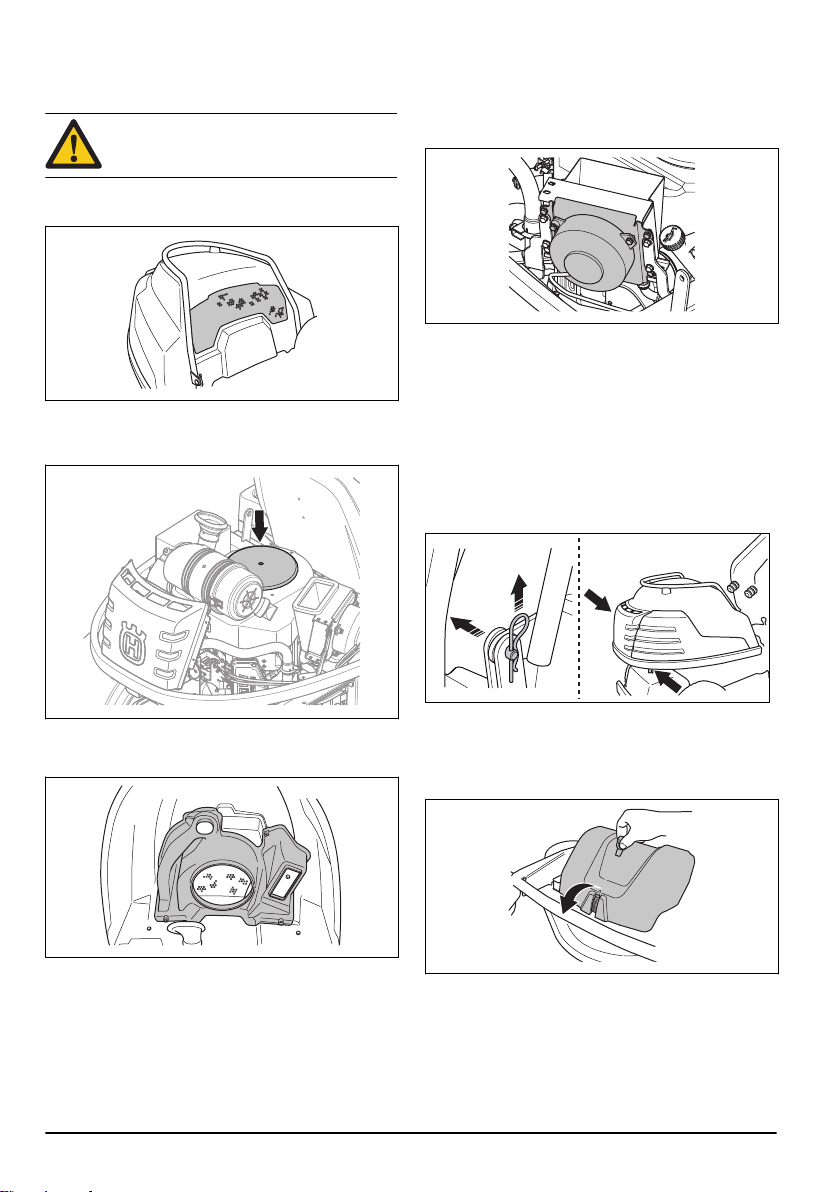
To clean the cold air intake of the engine
WARNING: Stop the engine. The cold air
intake rotates and can cause injury to your
fingers.
1. Make sure that the air intake grille is not blocked.
Remove grass and dirt with a brush.
2. Remove the engine cover.
3. Make sure that the cold air intake is not blocked.
Remove grass and dirt with a brush.
To clean the hydraulic oil cooler
Make sure that the fan for the hydraulic oil cooler is not
blocked and that the area around the hydraulic oil cooler
is clean. Remove grass and dirt with a brush.
To remove the covers
To remove the engine cover
1. Move the seat fully forward. See
on page 16
2. Tilt the seat forward.
3. Remove the cotter pins and clevis pins from the
hinges behind the seat.
4. Pull the clips on the engine cover rearward. The clips
are found on the inner surface of the engine frame.
.
To adjust the seat
4. Examine the air duct on the inner surface of the
engine cover. Make sure that the air duct is clean
and does not rub against the cold air intake.
24
5. Lift and remove the engine cover.
To remove the front cover
1. Release the clip on the front cover with the tool
attached to the ignition key.
242 - 003 -
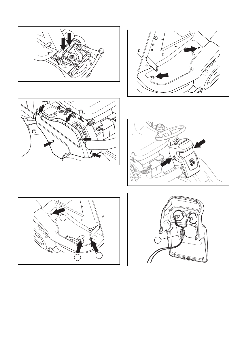
2. Remove the front cover. It is attached to the
A
B
C
A
equipment frame with 2 hooks.
To remove the side cover
• Remove the 5 screws and remove the side cover.
To remove the right footrest plate
1. Turn and remove the knob on the rearward drive
pedal (A).
2. Remove the 2 screws (B and C) and remove the
footrest plate.
To remove the left footrest plate
• Remove the 2 screws and remove the footrest plate.
To replace a broken lamp
1. Remove the 2 screws, one on each side, and
remove the cover.
2. Disconnect the cables at the connection (A).
242 - 003 -
25
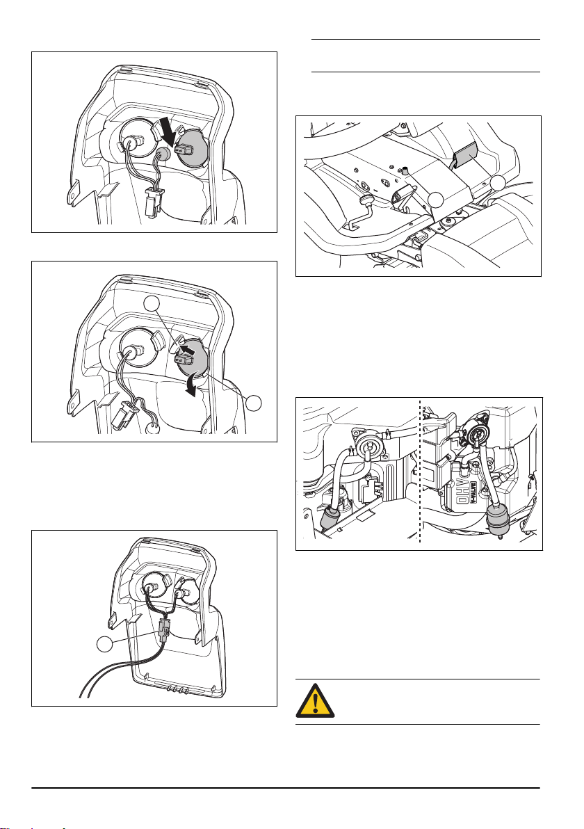
3. Disconnect the cables from the broken lamp.
B
C
A
B
A
4. Push the broken lamp toward the inner lamp
attachment (B).
Do not park the product on a grass slope when
Note:
you do a check of the parking brake.
2. Press the parking brake pedal down (A).
3. Press and hold the lock button (B) and release the
parking brake pedal while the button is pressed.
4. If the product starts to move, let an approved service
agent adjust the parking brake.
5. Press the parking brake pedal again to release the
parking brake.
To replace the fuel filter
1. Remove the engine cover to get access to the fuel
filter. The right illustration shows P 524. The left
illustration shows P 524EFI.
5. Lift the outer edge (C) of the lamp to remove the
lamp.
6. Replace the broken lamp. Use the type of lamp as
given in
Technical data on page 44
7. Connect the cables to the new lamp.
8. Connect the cables at the connection (A).
.
9. Attach the cover and tighten the 2 screws.
To do a check of the parking brake
1. Park the product on a hard surface that slopes.
26
2. Move the hose clips away from the fuel filter with a
pair of flat pliers.
3. Pull off the fuel filter from the hose ends.
4. Press the new fuel filter into the ends of the hoses.
Apply liquid detergent to the ends of the fuel filter to
make the connection easier.
5. Push the hose clips against the fuel filter.
To clean and replace the air filter
CAUTION: Do not start the engine when the
air filter is not attached.
1. Remove the engine cover.
242 - 003 -
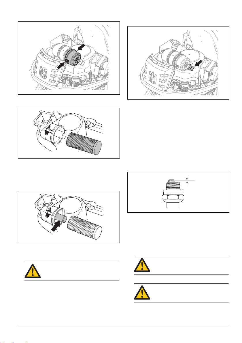
2. Loosen the 2 knobs that hold the air filter cover.
3. Remove the the air filter cover.
4. Remove the air filter cartridge from the filter housing.
5. Hit the air filter cartridge carefully against a hard
surface and blow with compressed air on the inner
surface. Replace the air filter if it does not become
clean or if it is damaged.
6. Remove the inner air filter behind the air filter
cartridge.
9. Attach the air filter cover and make sure that the
particle collector points down.
To examine and replace the spark plug
1. Open the engine cover.
2. Remove the ignition cable shoe and clean around
the spark plug.
3. Remove the spark plug with a ¾ʺ (19 mm) spark
plug wrench.
4. Examine the spark plug. Replace it if the electrodes
are burned or if the insulation has cracks or
damages. If the spark plug is not damaged, clean it
with a steel brush.
5. Measure the electrode gap and make sure that it is
correct. See
Technical data on page 44
.
6. Bend the side electrode to adjust the electrode gap.
7. Put the spark plug back in and turn it by hand until it
touches the spark plug seat.
8. Tighten the spark plug with the spark plug wrench
until the washer is compressed.
7. Hit the inner air filter against a hard surface to clean
it. Replace the air filter if it does not become clean or
if it is damaged.
CAUTION: Do not use compressed air to
clean the inner air filter.
8. Put the inner air filter and the air filter cartridge back
in their initial positions in the filter housing. Make
sure that the air filter cartridge is correctly attached
on top of the air intake.
242 - 003 - 27
9. Tighten a used spark plug ⅛ of a turn more, and a
new spark plug ¼ turn more.
CAUTION:
tightened correctly can cause damage to
the engine.
10. Replace the ignition cable shoe.
CAUTION:
if the spark plug or ignition cable is
removed.
Spark plugs that are not
Do not try to start the engine
To replace a fuse
B
A
C
D
A broken fuse is identified by a burned connector.
1. Remove the cover to get access to the broken fuse.
a) To replace the main fuse, remove the engine
cover. The main fuse is in a holder below the
battery. The right illustration shows P 524. The
left illustration shows P 524EFI.
b) To replace the fuse for the power outlet, remove
the side cover. The fuse for the power outlet is
below the control panel.
• Always disconnect the charger before starting the
engine.
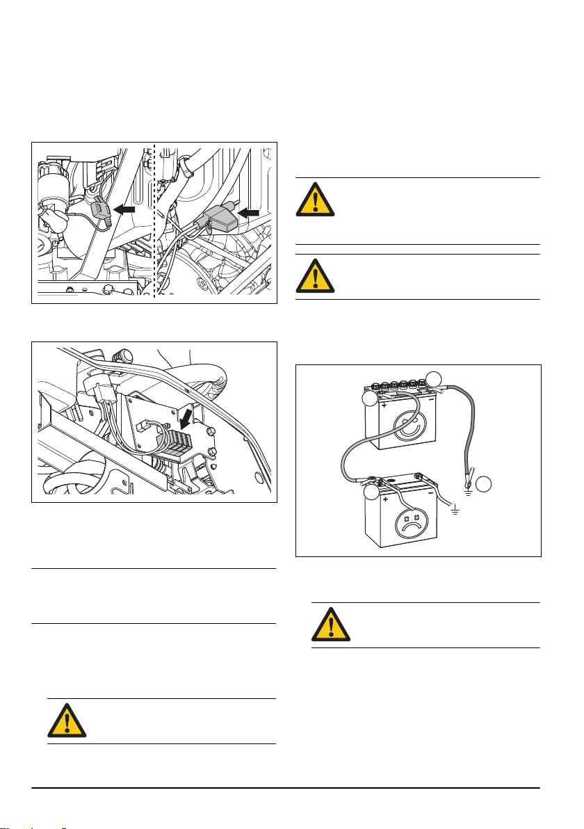
To do an emergency start of the engine
If the battery is too weak to start the engine, you can use
jumper cables to do an emergency start. This product
has a 12 V system with negative ground. The product
that is used for the emergency start must also have a 12
V system with negative ground.
To connect the jumper cables
WARNING: Risk of explosion because of
explosive gas that comes from the battery.
Do not connect the negative terminal of the
fully charged battery to or near the negative
terminal of the weak battery.
CAUTION: Do not use the battery of your
product to start other vehicles.
1. Remove the engine cover.
2. Remove the cover for the battery case.
3. Connect one end of the red cable to the POSITIVE
battery terminal (+) on the weak battery (A).
2. Pull the fuse from the holder.
3. Replace the blown fuse with a new fuse of the same
type. Refer to
4. Attach the covers.
Note: If the main fuse breaks again a short period after
you replace it, there is a short circuit. Repair the short
circuit before you operate the product again. Let an
approved service agent help you.
Technical data on page 44
.
To charge the battery
• Charge the battery if it is too weak to start the
engine.
• Use a standard battery charger.
28
CAUTION:
or start booster. That will cause damage
to the electrical system of the product.
Do not use a boost charger
4. Connect the other end of the red cable to the
POSITIVE battery terminal (+) on the fully charged
battery (B).
WARNING: Do not short circuit the ends
of the red cable against the chassis.
5. Connect one end of the black cable to the
NEGATIVE battery terminal (-) on the fully charged
battery (C).
6. Connect the other end of the black cable to a
CHASSIS GROUND (D), away from the fuel tank
and the battery.
7. Replace the covers.
242 - 003 -
To remove the jumper cables
A
Note: Remove the jumper cables in the opposite
sequence to how you connect them.
1. Remove the BLACK cable from the chassis.
2. Remove the BLACK cable from the fully charged
battery.
3. Remove the RED cable from the 2 batteries.
Tire pressure
We recommend a tire pressure of 100 kPa (1.0 bar /
14.5 PSI) on all 4 tires.
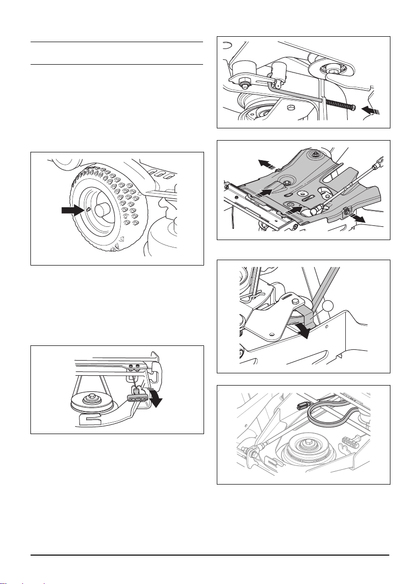
To replace the drive belt for the cutting deck
1. Lower the cutting deck.
2. Remove the front cover.
3. Pull the spring handle to the left out from the spring
holder to loosen the tension on the tension wheel for
the drive belt.
5. Pull the spring stay from the lift chain.
6. Remove the 4 screws and remove the belt guard.
7. Remove the belt from the pulley, lift the belt holder
(A) and remove the belt from the tension wheel.
4. Remove the left side cover on the cutting deck.
242 - 003 -
8. Remove the belt from the pulley on the tool frame.
29
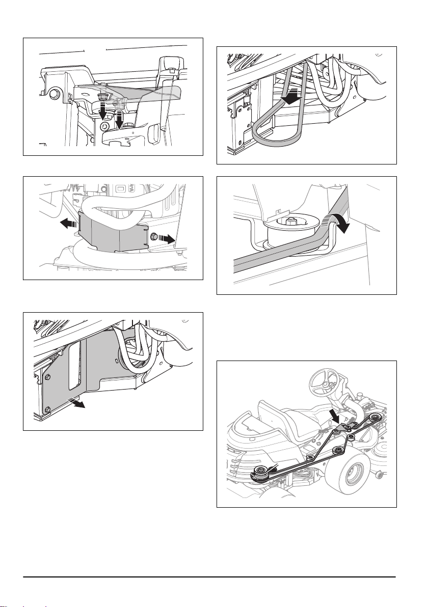
9. Remove the belt guard below the engine pulley.
10. Remove the belt guard in front of the rear
transmission.
11. Remove the belt from the engine pulley.
12. Remove the belt guard on the right side of the
machine.
13. Pull the front part of the belt out through the right
side of the articulation of the product.
14. Remove the belt from the hook on the center pulley.
15. Pull the drive belt out.
16. Attach a new drive belt in the opposite sequence.
Make sure that the drive belt for the cutting deck is
attached as the illustration shows. Make sure that it is
put correctly in the adjuster pulley, identified by an arrow
in the illustration.
To put the cutting deck in servicing position
1. See steps 1–8 in
page 15
30
To remove the cutting deck on
.
242 - 003 -
 Loading...