

Ed.01 - 11/2011
NUDA 900 MY12
NUDA 900 R MY12
SPECIFICATIONS - OPERATION - MAINTENANCE
EN - 1
EN
Unless specified, data and prescription are referred to all the models.

SPECIFICATIONS - OPERATION - MAINTENANCE
EN - 2
SUMMARY Page
PRESENTATION ............................................................3
IMPORTANT NOTICES....................................................3
INTENDED USE .............................................................4
GENERAL RECOMMENDATIONS .....................................4
IDENTIFICATION DATA ..................................................6
TECHNICAL DATA ..........................................................7
TABLE FOR LUBRICATION, SUPPLIES ..............................8
MOTORCYCLE OVERALL VIEW .......................................9
CONTROLS .................................................................11
COMBINED DASHBOARD.............................................12
RIDING
.......................................................................19
SUSPENSION SETTINGS SUMMARY TABLES ..................35
APPENDIX ..................................................................46
PRE-DELIVERY INSPECTION .........................................48
ALPHABETICAL INDEX ................................................. 49
SCHEDULED MAINTENANCE ..........................APPENDIX A
Note
lReferences to the “left” or “right” of the motorcycle
are considered from the point of view of a person facing forward.
lZ: number of teeth
l A: Austria
AUS: Australia
B: Belgium
BR: Brazil
CDN: Canada
CH: Switzerland
D: Germany
E: Spain
F: France
FIN: Finland
GB: Great Britain
I: Italy
J: Japan
USA: United States of America
lUnless otherwise specified, all the data and the in-
structions refer to all Countries.
SPECIFICATIONS - OPERATION - MAINTENANCE
EN - 3
EN
PRESENTATION
Welcome to the Husqvarna motorcycling family!
Your new Husqvarna motorcycle is designed and manufactured to be the best in its field. The instructions in
this book have been prepared to provide a simple and
understandable guide for your motorcycle’s operation
and care. Follow the instructions carefully to obtain
maximum performance and your personal motorcycling
pleasure. Your owner’s manual contains instructions
for owner care and maintenance. The main repair or
maintenance work requires the attention of a skilled
mechanic and the use of special tools and equipment.
Your Husqvarna Dealer has the facilities, experience and
original parts necessary to properly render this valuable
service.
This “Owner’s Manual” is part and
parcel of the motorcycle, hence, it shall
remain with the motorcycle even when
sold to another user.
This motorcycle uses components designed thanks to
systems and state-of-the-art technologies which are
thereafter tested in competitions.
In racing motorcycles, every detail is verified after each
race in order to guarantee better performance at all
times.
To ensure trouble-free operation of the motorcycle, the
maintenance and inspection table found under Appendix A must be complied with.
IMPORTANT NOTICES
1) NUDA 900 models are designed for ROAD use,
guaranteed free from faults, and covered by legal warranty provided that NO CHANGE IS MADE TO THE STANDARD SETTING and that the intervals specified in maintenance table of Appendix A are complied with.
2) All the motorcycles and any of their
parts used in competitions of any type
are excluded from the warranty.

SPECIFICATIONS - OPERATION - MAINTENANCE
EN - 4
WARNING*:
Indicates the possibility of severe personal injury or death if instructions are
not followed.
CAUTION*:
Indicates the possibility of personal injury or vehicle damage if instructions
are not followed.
Note*:
Gives helpful information.
Parts Replacement
When parts replacement is required, use only Husqvarna
ORIGINAL parts.
WARNING*: After a crash, inspect the
motorcycle carefully. Make sure that
the throttle control, brake, clutch and all
other systems are undamaged. Riding
with a damaged motorcycle can lead to
a serious accident.
WARNING*: Never attempt to start or
operate your motorcycle unless you are
wearing appropriate protective clothing. Always wear a motorcycle helmet,
boots, gloves, goggles and other appropriate protective clothing.
PRECAUTIONS FOR CHILDREN
WARNING*:
l Park the vehicle where it is unlikely
to be bumped into or damaged.
Even slight or involuntary bumps can
cause the vehicle to tip over, with sub-
IMPORTANT
In order to maintain the vehicle’s “Guarantee of Functionality”, the client must
follow the maintenance programme indicated in the user’s manual by carrying
out maintenance inspections at authorised HUSQVARNA dealers.
The cost for replacing parts and the labour required to comply with the maintenance plan is charged to the Client.
NOTE: the warranty is NULL AND VOID if
the motorcycle is rented.
WARNING*:
ALWAYS remember that all the motorcycles and their parts used in competitions of any type are excluded from the
warranty and that all modications to
standard conguration cause THE VE-
HICLE NON COMPLIANCE WITH TYPE-AP-
PROVAL REQUIREMENTS and it is hence
unsuitable for circulating on public
roads: consequently it may be used only
in “CLOSED CIRCUITS” by authorised subjects holding the relevant driving licence
or authorisation.
Important Notice
Read this manual carefully and pay special attention to
statements preceded by the following words:
sequent risk of serious harm to people or children.
l To prevent the vehicle from tipping
over, never park it on soft or uneven
ground, nor on asphalt strongly heated by the sun.
l Engine and exhaust pipes become
very hot during riding. Always park
your motorcycle where people or children can not easily reach these parts,
in order to avoid serious scalds.
l Do not leave the vehicle unattended
with the engine running or the key in
the ignition.
INTENDED USE
This motorcycle has been manufactured so as to withstand standard road stresses.
GENERAL RECOMMENDATIONS
Read these general recommendations carefully before
using the vehicle.
Carbon monoxide
Only run the engine in an open or very well ventilated
area. If you do work in an enclosed area, make sure
you use a fume extraction system.
WARNING*:
Exhaust emissions contain carbon monoxide, a poisonous gas which can cause
loss of consciousness and even death if
inhaled.
SPECIFICATIONS - OPERATION - MAINTENANCE
EN - 5
EN
Parts of the vehicle that become hot
Before working on the engine and the exhaust unit,
wait for them to cool down; while the vehicle is running, these parts become very hot and remain hot for
some time after turning off the engine.
CAUTION*:
Risk of burns - work with caution and
wear suitable PPE if necessary.
Fuel
WARNING*:
The fuel used to power internal combustion engines is highly flammable
and explosive.
Refuel in ventilated areas with the
engine switched off; do not smoke
and avoid contact between the fuel
and naked flames, sparks, etc. that
may cause an explosion.
Do not dispose of fuel in the environment.
Keep out of reach of children.
CAUTION*:
Do not tilt the vehicle excessively since
this may cause fuel to leak.
Engine
In some cases, coolant may become inflammable and
if burnt, produce invisible flames which cause burns.
WARNING*:
Do not spill coolant onto hot components like the engine or exhaust pipe,
etc. since it may ignite.
During maintenance work, wear latex
gloves.
Never leave the coolant in open containers in areas accessible to children and
animals since it is toxic.
DO NOT remove the radiator cap when
the engine is hot; the coolant is pressurised and may cause scalding.
Engine oil
CAUTION*:
Do not dispose of oil in the environment
since it is highly polluting.
Keep out of reach of children.
Wear latex gloves since prolonged contact with the skin can cause serious
damage.
Send used oil to special authorised recyclers in accordance with the legal requirements in force in the country where
the vehicle will be used.
Brake fluid
WARNING*:
Brake fluid is highly corrosive and may
damage the rubber and painted parts of
the vehicle.
While performing maintenance work,
protect your eyes by wearing special
goggles and wear protective gloves.
In the event of accidental contact with
the eyes, rinse them with plenty of
clean, running water and seek medical
advice immediately.
Keep out of reach of children.
Battery
WARNING*:
Recharge the battery in well ventilated
areas since the battery produces toxic,
highly inflammable gases when being
recharged; do not smoke or use naked
flames or sparks.
The liquid in the battery is highly corrosive. If it comes into contact with the
skin, rinse thoroughly with running water. It is extremely important to protect
your eyes because even a small amount
of liquid can cause irreversible damage
to the eyes.
ZKHA700A#CV000001
NUDA 900
(l) (▲)
(
♦
)
ZKHA700B#CV000001
(l) (▲) (♦)
NUDA 900 R
1
2
SPECIFICATIONS - OPERATION - MAINTENANCE
EN - 6
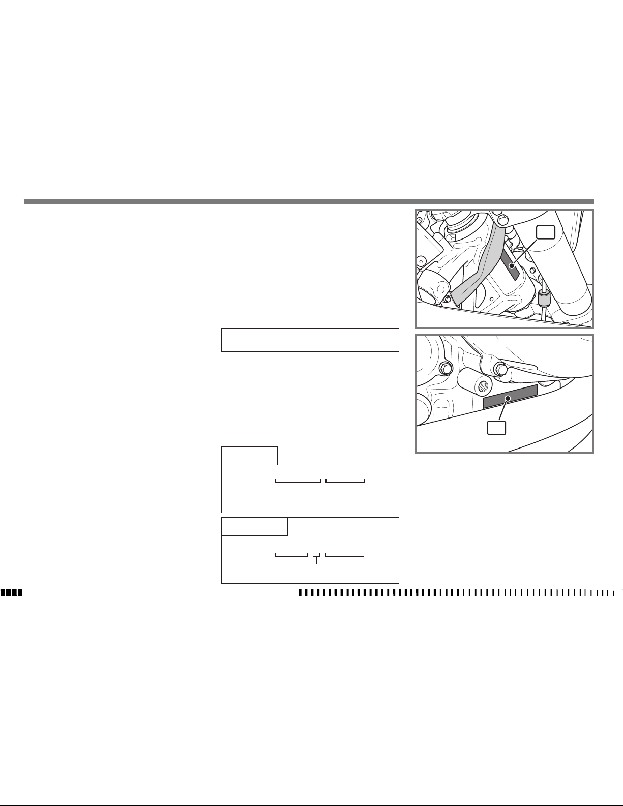
IDENTIFICATION DATA
The engine identification number is stamped on the bottom RH side of the crankcase whereas the motorcycle serial number is stamped on the steering tube.
Always quote the number stamped on the
frame when ordering spare parts or requesting further
details about your vehicle and note it on this booklet.
CHASSIS NUMBER
VEHICLE IDENTIFICATION NUMBER (V.I.N.)
The full 17-digit serial, or Vehicle Identification Number, is
stamped on the steering tube (R.H. side).
(
l
) = Model designation
(▲) = Model Year (2012)
(♦) = Progressive no.
1. Chassis serial number
2. Engine serial number
If it comes into contact with the eyes,
rinse thoroughly with clean, running
water and if swallowed accidentally,
drink plenty of water or milk.
In all cases, seek medical advice immediately.
The battery liquid is corrosive and
should not be poured onto the painted
or rubber parts.
The battery liquid is highly polluting. DO
NOT dispose in the environment; at the
end of its service life, take the battery
to the special authorised recycling centres in accordance with the legal requirements in force in the country where the
vehicle will be used.
Keep out of reach of children.

SPECIFICATIONS - OPERATION - MAINTENANCE
EN - 7
EN
TECHNICAL DATA
ENGINE
Inline twin cylinder, 4 stroke, with four valves per cylinder
Cooling ....................liquid and electric fan
Bore . . . . . . . . . . . . . . . . . . . . . . . . . 3,31 in. (84 mm)
Stroke ........................3,19 in. (81 mm)
Displacement . . . . . . . . . . . . . . . . . 54,8 in
3
(898 cm3)
Compression ratio . . . . . . . . . . . . . . . . . . . . . . . . 13:1
Starting . . . . . . . . . . . . . . . . . . . . . . . . . . . . . . electric
Type of fuel .............unleaded fuel 95ROZ/RON
TIMING SYSTEM
Type . . . . . . double overhead camshaft chain operated;
4 valves per cylinder
Valve clearance (with engine cold)
Intake .........0,0091 ÷ 0,013 in. (0.23 ÷ 0.33 mm)
Exhaust ......0,0118 ÷ 0,0161 in. (0.30 ÷ 0.41 mm)
LUBRICATION
Type . . . . . . . . . . dry sump oil circuit with built-in tank,
cartridge filter and oil/water heat exchanger
IGNITION
Type . . . . . . . . . . . . . . . . . . . .Electronic with adjustable
advance (digital control)
Spark plug type . . . . . . . . . . . . . . . . “NGK” LMAR8C-9
Spark plug electrode gap
..........0,0315 ÷ 0,0354 in. (0.8 ÷ 0.9 mm)
FUEL SYSTEM
Type . . . . . . . . . . . . . . . . . . . . .Electronic injection feed
PRIMARY DRIVE
Drive gear on crankshaft ....................Z 35
Driven gear on clutch housing ................Z 68
Transmission ratio . . . . . . . . . . . . . . . . . . . . . . . 1.943
CLUTCH
Type . . .oil bath multiple disc clutch, mechanical control
TRANSMISSION
Type . . . . . . . . . . . . . . . . . . . . constant mesh gear type
Transmission ratio
1st gear . . . . . . . . . . . . . . . . . . . . . . . . 2.462 (32/13)
2nd gear ........................1.750 (28/16)
3rd gear ........................1.381 (29/21)
4th gear . . . . . . . . . . . . . . . . . . . . . . . . 1.174 (27/23)
5th gear . . . . . . . . . . . . . . . . . . . . . . . . 1.042 (25/24)
6th gear . . . . . . . . . . . . . . . . . . . . . . . . 0.960 (24/25)
SECONDARY DRIVE
Transmission sprocket (NUDA 900) ............Z 17
Transmission sprocket (NUDA 900 R) ...........Z 16
Rear wheel sprocket . . . . . . . . . . . . . . . . . . . . . . . Z 42
Transmission ratio (NUDA 900) ...............2.47
Transmission ratio (NUDA 900 R) . . . . . . . . . . . . 2.625
Transmission chain dimensions . . .5/8” x 5/16” (525)
FINAL RATIOS
NUDA 900
1st gear . . . . . . . . . . . . . . . . . . . . . . . . . . . . . . 11,815
2nd gear ...............................8,398
3rd gear ...............................6,627
4th gear . . . . . . . . . . . . . . . . . . . . . . . . . . . . . . . 5,634
5th gear . . . . . . . . . . . . . . . . . . . . . . . . . . . . . . . 5,000
6th gear . . . . . . . . . . . . . . . . . . . . . . . . . . . . . . . 4,607
NUDA 900 R
1st gear . . . . . . . . . . . . . . . . . . . . . . . . . . . . . . 12,557
2nd gear ...............................8,925
3rd gear ...............................7,043
4th gear . . . . . . . . . . . . . . . . . . . . . . . . . . . . . . . 5,987
5th gear . . . . . . . . . . . . . . . . . . . . . . . . . . . . . . . 5,314
6th gear . . . . . . . . . . . . . . . . . . . . . . . . . . . . . . . 4,896
CHASSIS
Type . . . . tubular steel trellis with removable steel rear
chassis.
FRONT SUSPENSION
NUDA 900
Type upside-down hydraulic fork
. . . . . . . . . . . . . . . . . .ø 1,89 in. (ø 48 mm) legs
Wheel travel . . . . . . . . . . . . . . . . . . 8,27 in. (210 mm)
NUDA 900 R
Type upside-down hydraulic fork (adjustable compres-
sion, rebound and spring reload)
...................ø 1,89 in. (ø 48 mm) legs
Wheel travel . . . . . . . . . . . . . . . . . . 8,27 in. (210 mm)
REAR SUSPENSION
NUDA 900
Type . . . . . . . . . . . . . . direct with hydraulic monoshock
(adjustable spring preload and hydraulic rebound damping)
Wheel travel . . . . . . . . . . . . . . . . . . 7,09 in. (180 mm)
NUDA 900 R
Type . . . . . direct with hydraulic monoshock (adjustable
spring preload and hydraulic compression and rebound
damping; adjustable length)
Wheel travel . . . . . . . . . . . . . . . . . . 7,09 in. (180 mm)

SPECIFICATIONS - OPERATION - MAINTENANCE
EN - 8
FRONT BRAKE
Type . . . . . . . . twin floating disc ø 12,6 in. (ø 320 mm)
with radial pump and radial callipers
REAR BRAKE
Type . . . . . . . . . . . . .fixed disc ø 10,43 in. (ø 265 mm)
and floating calliper
RIMS
Front .....................in light alloy: 3.5”x17”
Rear . . . . . . . . . . . . . . . . . . . . .in light alloy: 5.5”x17”
TYRES
Front ...........................120/70xZR17”
Rear . . . . . . . . . . . . . . . . . . . . . . . . . . .180/55xZR17”
Cold tyre pressure
Front .....................32,71 psi (2.3 kg/cm
2
)
Rear . . . . . . . . . . . . . . . . . . . . . 35,55 psi
(2.5 kg/cm2)
DIMENSION, WEIGHT, CAPACITY
Wheelbase .................58,86 in. (1495 mm)
Overall length ...............86,22 in. (2190 mm)
Overall width ................35,16 in. (893 mm)
Max. height . . . . . . . . . . . . . . . . 48,03 in. (1220 mm)
Seat height (NUDA 900) ........34,25 in. (870 mm)
Seat height (NUDA 900 R) . . . . . . . . 34,45 ÷ 35,04 in.
(mm 875 ÷ 890)
Min. ground clearance ...........7,68 in. (195 mm)
Kerb weight, without fuel. ........407,85 lb (185 kg)
Dry weight . . . . . . . . . . . . . . . . . . . 383,6 lb. (174 kg)
Fuel tank capacity reserve included . . . .2,86 Imp. Gall
3,43 U.S. Gall.
13 l
Fuel reserve . . . . . . . . . . . . . . .approx. 0,66 Imp. Gall.
approx. 0,79 U.S. Gall.
approx. 3 l
Coolant tank capacity . . . . . . . . . . . . . . 0,31 Imp. Gall.
0,37 U.S. Gall.
1.4 l
Transmission oil
Oil and oil filter replacement .........0,73 imp. Gall.
0,87 U.S. Gall.
3.3 l
Oil replacement ....................0,7 Imp. Gall.
0,85 U.S. Gall.
3.2 l
Oil top up between minimum and maximum
level ............................0,09 Imp. Gall
0,11 U.S. Gall.
0.4 l
TABLE FOR LUBRICATION, SUPPLIES
Engine, gearbox and primary drive lubricating oil
1)
CASTROL POWER1 RACING SAE 5W-40
2) SAE rating: 15W-40 API: SG/SH JASO: MA
Engine coolant .........CASTROL MOTORCYCLE COOLANT
Brake fluid ..........CASTROL RESPONSE SUPER DOT 4
Grease lubrication .............CASTROL LM GREASE 2
Secondary drive chain lubrication
....................
CASTROL CHAIN LUBE RACING
Electric contact protection
. . . . . . . . . . . . . CASTROL METAL PARTS CLEANER
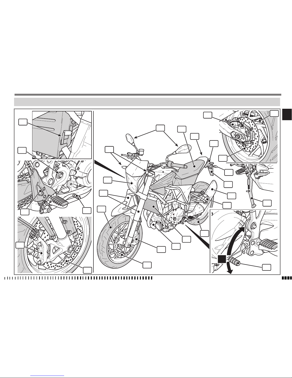
LEGEND
1. Front wheel
2. Left-hand front brake disc
3. Right-hand front brake disc
4. Left-hand front brake calliper
5. Right-hand front brake calliper
6. Front fork
7. Gear shift pedal (the first gear is engaged by
pushing lever downwards; for other gears push
it upwards. The neutral gear is between the first
and second gear)
8. Side stand
9. Rear sprocket
10. Rear wheel
11. Number plate holder
12. Rear turning indicators
13. Tail light
14. Saddle
15. Rear-view mirrors
16. Front turning indicators
17. Headlight
18. Rear brake control pedal
19. Rear brake master cylinder
20. Front sprocket
21. Rear brake disc
22. Rear brake calliper
23. Passenger footrests
24. Passenger grab handles
25. Silencer
26. Radiator
27. Oil filter
28. Allen wrench for saddle removal
28
20
19
18
5
3
2
4
27
26
1
6
17
16
15
14
13
24
22
9
21
12
11
25
23
10
8
7
1
2
3
4
5
6
N
SPECIFICATIONS - OPERATION - MAINTENANCE
EN - 9
EN
MOTORCYCLE OVERALL VIEW
30
33
34
31
32
35
36
37
38
29
SPECIFICATIONS - OPERATION - MAINTENANCE
EN - 10
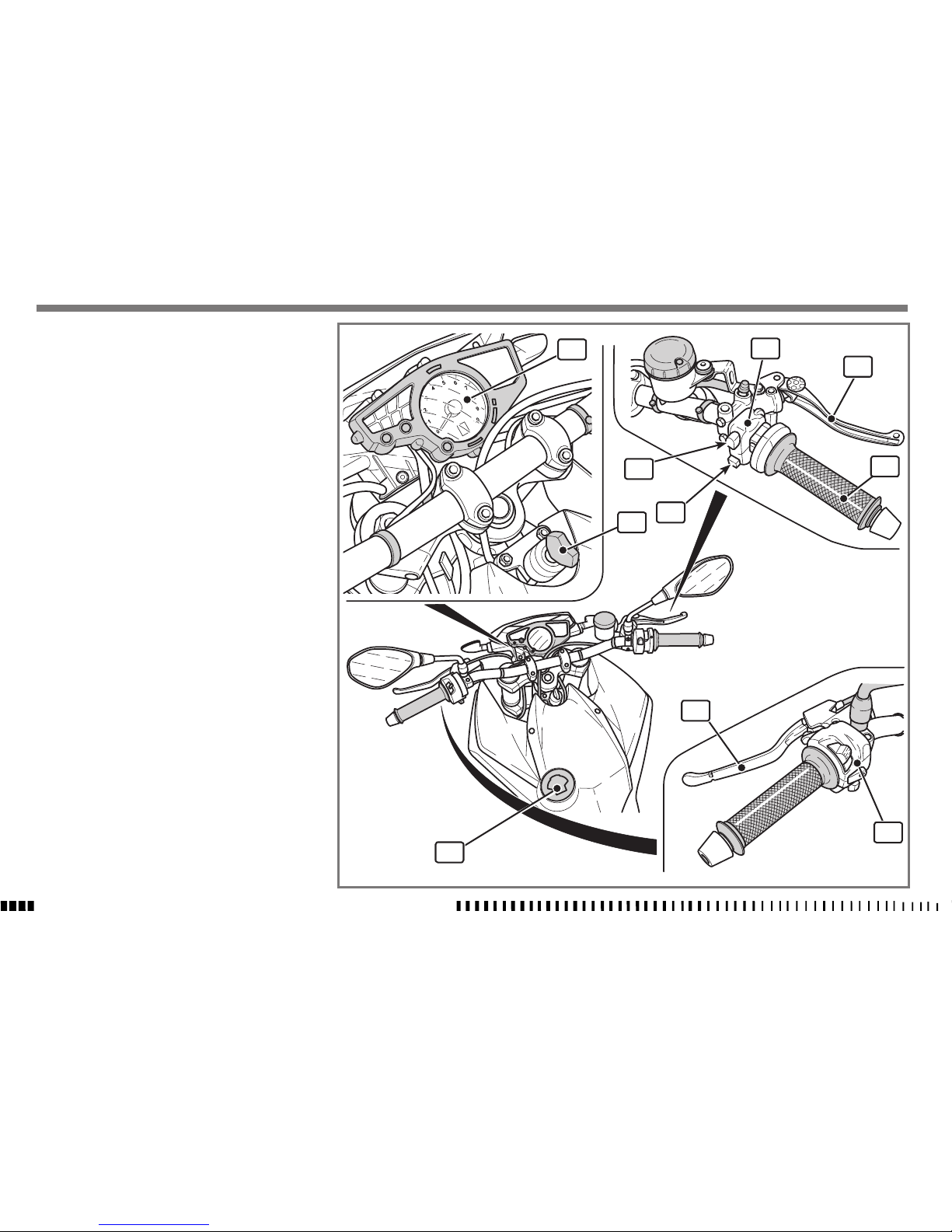
29. Fuel tank filler cap
30. Digital dashboard
31. Ignition switch
32. Right-hand switch
33. ENGINE STOP button (emergency stop)
34. Engine start button
35. Front brake control lever
36. Throttle twistgrip
37. Clutch control lever
38. Left-hand switch
1
2
3
A
1
2
4
SPECIFICATIONS - OPERATION - MAINTENANCE
EN - 11
EN
CONTROLS
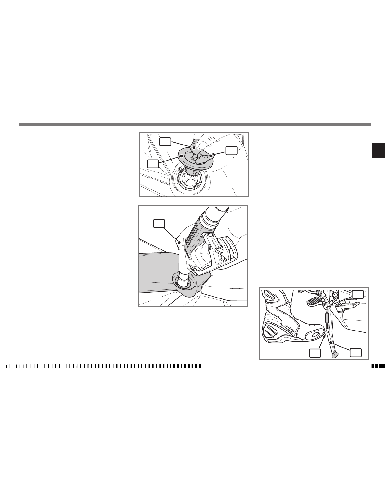
REFUELLING
Use UNLEADED petrol with octane rating of 95 or
higher only.
CAUTION*:
Using leaded fuel causes permanent
damage to the catalytic converter
which loses its effectiveness.
WARNING*:
Fuel is extremely flammable and can be
explosive under certain conditions. Always stop the engine and do not smoke
or allow flames or sparks in the area
where the motorcycle is refuelled or
fuel is stored.
WARNING*:
Do not overfill the tank. Refer to the
lower mark on filler. After refuelling,
make sure the tank cap (3) is closed securely.
- Lift the flap (1), insert the key (2), turn it counterclockwise and remove the tank cap (3).
- Fully insert the fuel pump nozzle (4) in the tank
before refuelling (see figure).
- After refuelling, replace the cap (3) turning it the
opposite way from when it was removed.
SIDE STAND
A side stand (1) is supplied with every motorcycle. To
lower it, put your foot on the lever (2).
WARNING*:
The stand is designed to support the
WEIGHT of the MOTORCYCLE ONLY. Do
not sit astride the motorcycle using the
stand for support as this could cause
structural failure to the stand resulting
in serious injury.
WARNING*:
The stand does NOT have automatic retraction.
The stand has a rotary type switch that
turns off the engine if a gear is engaged
when the stand is lowered.
Periodically check the side stand (see “Scheduled Maintenance Chart”); make sure that the springs are not damaged and the side stand freely moves. If the side stand is
noisy, lubricate the fastening pivot (A).
1
7
8
9
6
5a
5b
5
4
3
2
SPECIFICATIONS - OPERATION - MAINTENANCE
EN - 12
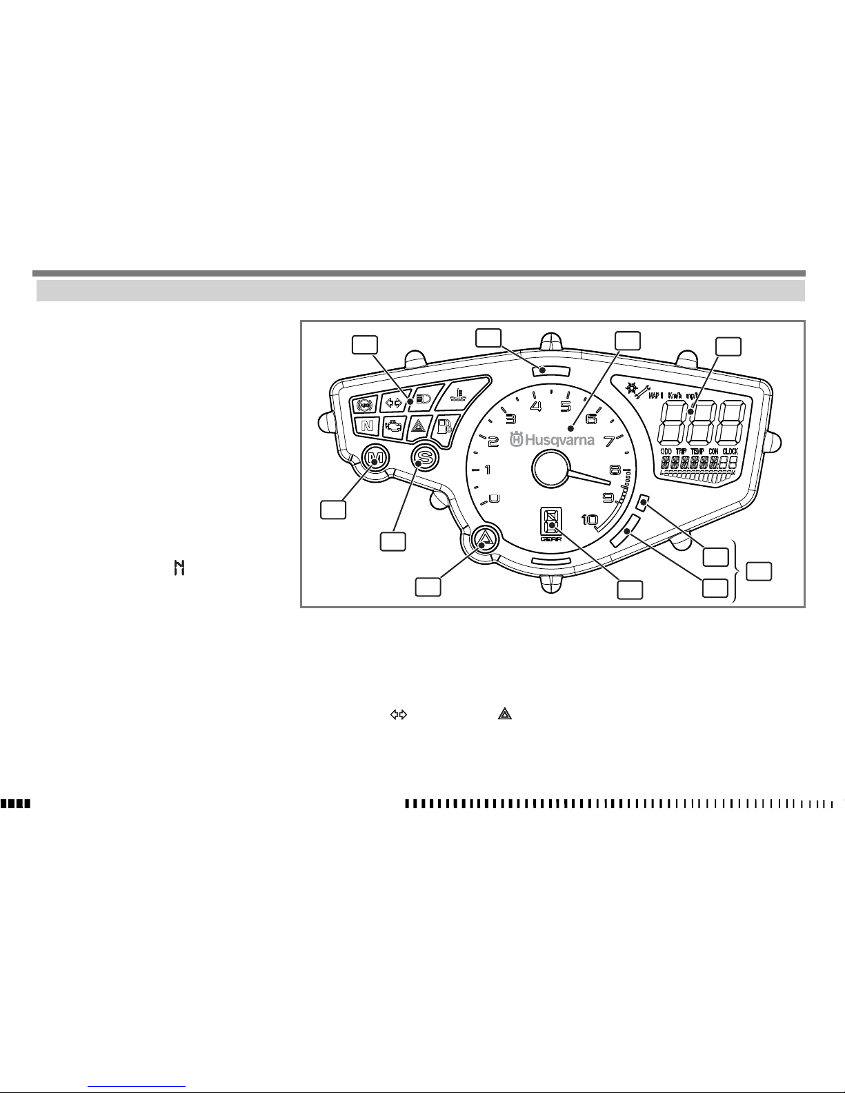
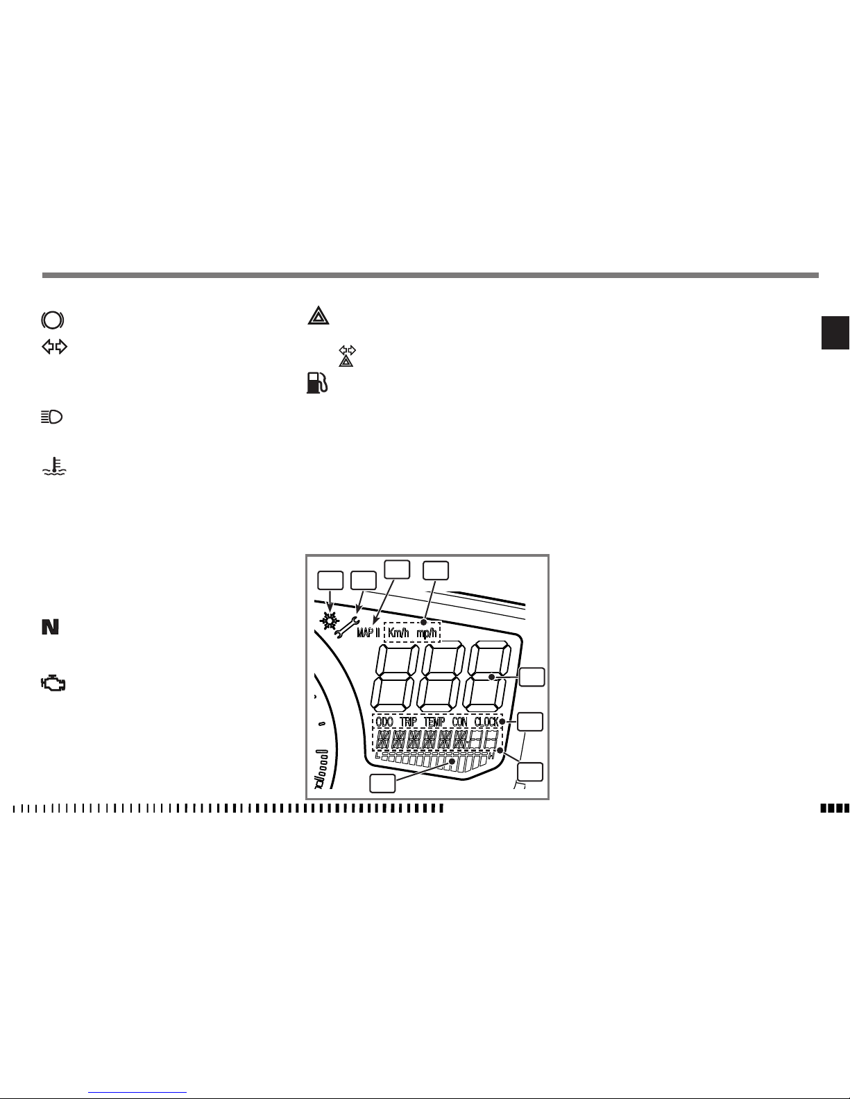
COMBINED DASHBOARD
The motorcycle has a combined dashboard divided into
the following areas:
1. Warning lights (see “Description of warning
lights”).
2. Multifunction display (see “ Description of multi-
function display”).
3. Rev meter
Indicates the engine rpm.
4. Alarm system warning light (RED).
5. Overrev warning lights (RED)
When 8500 rpm is reached, warning light (5a)
comes on. When 9000 rpm is reached, warning
light (5a) stays on together with warning light
(5b)
6. Engaged gear display
This indicates the engaged gear; neutral is indi-
cated with this symbol “ ”.
7. “MODE” button
Vehicle performance can be varied by selecting
“RAIN” mapping.
The ECU memorises two different mappings that
can be selected using the “MODE” button (see
specific section).
The standard configuration delivers maximum
engine power. The second mapping delivers
power than can be used more at low and medium revs and is suitable when using the vehicle
on wet roads or low grip situations (see “Map
change”).
8. “SET” button
This displays the various functions of the multi-
function display (see “Description of multifunction display”).
9. "HAZARD" button
When this is pressed, the turning indicators,
warning light
and warning light flash
at the same time.
Press it again to deactivate the hazard warning
lights.
1 2
3
4
5
6
7
8
SPECIFICATIONS - OPERATION - MAINTENANCE
EN - 13
EN
Description of warning lights
ABS
“ABS” warning light (not used).
Turning indicator warning light (GREEN)
This flashes when the turning indicators have
been turned on or the “HAZARD” button has
been pressed.
High beam warning light (BLUE)
This lights up permanently when the high beam
is on.
High coolant temperature warning light (RED).
This lights up permanently when the coolant
reaches the alarm temperature;
Slow down until you come to a stop, let the
engine idle and wait for the temperature to
decrease (scale shown on display) and the
warning light to go out.
If the problem persists, check the coolant level
in the expansion tank. If the liquid level is correct, contact your HUSQVARNA dealer.
Neutral warning light (GREEN)
This lights up permanently when the motorcy-
cle is in neutral.
Engine diagnosis warning light (ORANGE)
This lights up permanently when the engine
ECU has diagnosed malfunctioning.
There are two types of fault:
- Critical fault: the engine switches off and
you must contact your HUSQVARNA dealer.
- Fault with emergency operating: the engine
operates with reduced performance to allow
you to reach the nearest HUSQVARNA dealer
to have the fault checked.
“HAZARD” warning light (RED)
This flashes together with the warning light
and the turning indicators when switch
has been pressed.
Fuel reserve warning light (ORANGE)
This comes on when there are approximately 3
litres of fuel left in the tank.
You need to refuel.
Note *:
the fuel light normally switch off a few time after
the fuel refilling operation.
Description of multifunction display
1. "ICE" indicator:
This appears when the external temperature is
lower than 3°C or 37.4°F
2. “SERVICE” indicator:
This indicates that it is time for a service.
Contact your HUSQVARNA dealer to have sched-
uled maintenance work carried out.
3. “MAP II” indicator:
This appears when “RAIN” mapping is selected
4. km/h or mp/h odometer scale indicator (see
“setting units of measurement”)
5. Speed indicator.
6. Display parameters:
This field is used to individually set the param-
eters below that will be displayed in (7).
ODO = Odometer / Total mileage
TRIP = Odometer / Partial mileage
(to set the functions, see “Setting parameters”)
TEMP = Air temperature (AIR BOX) / Coolant
temperature
CON = Actual fuel consumption / Average con-
sumption.
CLOCK = Clock ( see “Clock adjustment”).
7. This displays the parameter set in (6).
8. This lights up in sequence from left to right as the
coolant temperature increases.
> 4”
> 4”
> 4”
> 4”
4”<
1
1
SPECIFICATIONS - OPERATION - MAINTENANCE
EN - 14
is automatically memorised after 10 seconds.
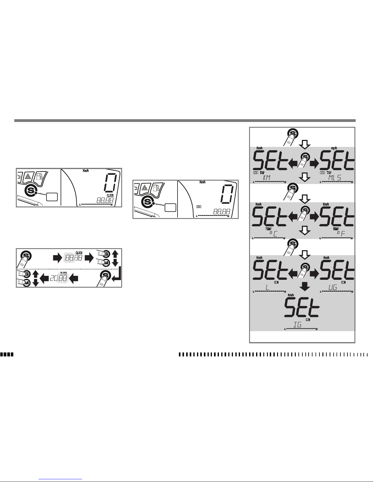
Setting units of measurement
The units of measurement must be set when the motorcycle is stationary and the key is set to ON.
- Press the “S” button (1) until the word “ODO” or
“TEMP” appears on the display.
Clock adjustment
The clock must be set when the motorcycle is stationary
and the key is set to ON.
The clock is set to 24 hours.
- Press the “S” button (1) until the word “CLOCK” appears on the display.
- Press the “S” button for more than 4 seconds and the
hours will flash on the display.
- The value of the hours increases by one unit each time
you press the “S” button.
- The value of the hours decreases by one unit each time
you press the “M” button.
- Press the “S” button for more than 4 seconds to memorise the hours set and the minutes will flash on the
display.
- The value of the minutes increases by one unit each
time you press the “S” button.
- The value of the minutes decreases by one unit each
time you press the “M” button.
- To memorise the time once you have set it, press the
“S” button for more than 4 seconds. If not, the setting
- Press the “S” button for more than 4 seconds. The word
“SET” appears on the display and the unit of measurement currently in use flashes.
- Press the “S” button once to change the unit of measurement. Once you have selected the unit of measurement, press the “S” button” for more than 4 seconds to
confirm the set data and go onto the next scale.
The following units of measurement can be set:
Km / mp = the display will show:
- the speed in “km/h” or “mp/h” ;
- the total distance covered in “km” or “mp”
- the partial “TRIP” distance covered in “km” or “mp”.
Temperature = °C / °F
Quantity of fuel:
L = (litres) - UG = US/GAL - IG = IM/GAL
- To quit the “SET” stage once you have made your last
setting, press the “S” button for more than 4 seconds. If
not, the program automatically quits after 10 seconds.
1
1
1
SPECIFICATIONS - OPERATION - MAINTENANCE
EN - 15
EN
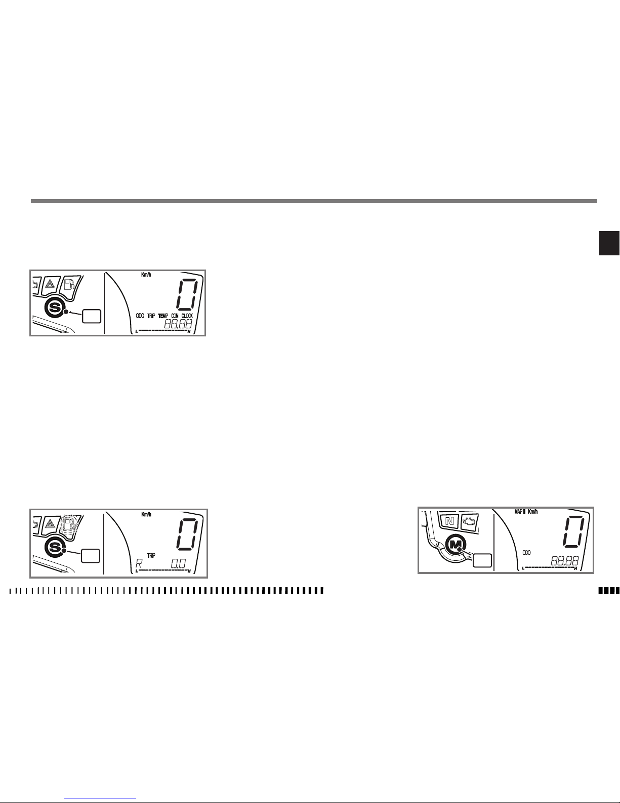
Setting parameters
With the dashboard on, press the “S” button (1) to display the various display functions:
ODO ; TRIP ; TEMP ; CON ; CLOCK
CON function:
When this function is activated, press the “S” button for
more than 4 seconds to reset and start a new count of the
litres/ gallons consumed from when average consumption (L/100 km) has been reset.
The “ODO”, “TEMP” and “CLOCK” functions are for display purposes only.
TRIP function:
When this function is activated, press the “S” button for
more than 4 seconds to reset and start a new partial
count of the kilometres /miles subsequently travelled.
When this function is set after the fuel reserve light has
come on, press the “S” button “S” (1) for more than 4
seconds to display fuel consumption (in litres or gallons
depending on the unit of measurement you have selected) from when you go onto fuel reserve.
Changing ECU mapping:
The vehicle leaves the factory in “STANDARD” configuration, i.e, with maximum power.
Motorcycle performance can be changed from “STANDARD” to “RAIN” by pressing the “M” button (1) on the
dashboard.
The map can be changed when the vehicle is moving
(key turned to “ON”) or stationary.
Press the “M” button for more than 3 seconds:
if the vehicle is moving, “MAP II” flashes intermittently
on the display and the “RAIN” configuration is activated
as soon as the accelerator is completely closed (“MAP II”
permanently lit on the display) whereas if the vehicle is
stationary, “MAP II” appears permanently lit after pressing the “M” button for more than 3 seconds.
To go from “RAIN” to “STANDARD” mapping, proceed in
the same way.
In “STANDARD” mode, there is no indication on the display.
When the vehicle is off (key turned to “OFF”) the current
mapping is always maintained.
 Loading...