

Husqvarna LR122 User Manual
LR122
OWNER'S MANUAL

SAFETY RULES
Safe Operation Practices for Ride-On Mowers
IMPORTANT: THIS CUTTING MACHINE IS CAPABLE OF AMPUTATING HANDS AND FEET AND THROWING OBJECTS.
FAILURE TO OBSERVE THE FOLLOWING SAFETY INSTRUCTIONS COULD RESULT IN SERIOUS INJURY OR DEATH.
I. GENERAL OPERATION
• Read, understand, and follow all instructions in the manual
and on the machine before starting.
• Only allow responsible adults, who are familiar with the
instructions, to operate the machine.
• Clear the area of objects such as rocks, toys, wire, etc.,
which could be picked up and thrown by the blade.
• Be sure the area is clear of other people before mowing. Stop
machine if anyone enters the area.
• Never carry passengers.
• Do not mow in reverse unless absolutely necessary. Always
look down and behind before and while backing.
• Be aware of the mower discharge direction and do not point
it at anyone. Do not operate the mower without either the
entire grass catcher or the guard in place.
• Slow down before turning.
• Never leave a running machine unattended. Always turn off
blades, set parking brake, stop engine, and remove keys
before dismounting.
• Turn off blades when not mowing.
• Stop engine before removing grass catcher or unclogging
chute.
• Mow only in daylight or good artificial light.
• Do not operate the machine while under the influence of
alcohol or drugs.
• Watch for traffic when operating near or crossing roadways.
• Use extra care when loading or unloading the machine into
a trailer or truck.
II. SLOPE OPERATION
Slopes are a major factor related to loss-of-control and
tipover accidents, which can result in severe injury or death.
All slopes require extra caution. If you cannot back up the
slope or if you feel uneasy on it, do not mow it.
DO:
• Mow up and down slopes, not across.
• Remove obstacles such as rocks, tree limbs, etc.
• Watch for holes, ruts, or bumps. Uneven terrain could
overturn the machine.
• Use slow speed. Choose a low gear so that you will not have
to stop or shift while on the slope.
• Follow the manufacturer’s recommendations for wheel
weights or counterweights to improve stability.
• Use extra care with grass catchers or other attachments.
These can change the stability of the machine.
• Keep all movement on the slopes
make sudden changes in speed or direction.
• Avoid starting or stopping on a slope. If tires lose traction,
disengage the blades and proceed slowly
slope.
DO NOT:
•
Do not
turn on slopes unless necessary, and then, turn slowly
and gradually downhill, if possible.
Do not
•
•
•
•
mow near drop-offs, ditches, or embankments. The
mower could suddenly turn over if a wheel is over the edge
of a cliff or ditch, or if an edge caves in.
Do not
mow on wet grass. Reduced traction could cause
sliding.
Do not
try to stabilize the machine by putting your foot on the
ground.
Do not
use grass catcher on steep slopes.
Tall grass can hide obstacles.
slow
and
gradual
. Do not
straight
down the
III. CHILDREN
Tragic accidents can occur if the operator is not alert to the
presence of children. Children are often attracted to the
machine and the mowing activity.
Never
assume that
children will remain where you last saw them.
• Keep children out of the mowing area and under the watchful
care of another responsible adult.
• Be alert and turn machine off if children enter the area.
• Before and when backing, look behind and
children.
• Never carry children. They may fall off and be seriously
injured or interfere with safe machine operation.
• Never allow children to operate the machine.
• Use extra care when approaching blind corners, shrubs,
trees, or other objects that may obscure vision.
down
IV. SERVICE
• Use extra care in handling gasoline and other fuels. They are
flammable and vapors are explosive.
- Use only an approved container.
- Never remove gas cap or add fuel with the engine
running. Allow engine to cool before refueling. Do not
smoke.
- Never refuel the machine indoors.
- Never store the machine or fuel container inside where
there is an open flame, such as a water heater.
• Never run a machine inside a closed area.
• Keep nuts and bolts, especially blade attachment bolts, tight
and keep equipment in good condition.
• Never tamper with safety devices. Check their proper
operation regularly.
• Keep machine free of grass, leaves, or other debris build-up.
Clean oil or fuel spillage. Allow machine to cool before
storing.
• Stop and inspect the equipment if you strike an object.
Repair, if necessary, before restarting.
• Never make adjustments or repairs with the engine running.
• Grass catcher components are subject to wear, damage, and
deterioration, which could expose moving parts or allow
objects to be thrown. Frequently check components and
replace with manufacturer's recommended parts, when necessary.
• Mower blades are sharp and can cut. Wrap the blade(s) or
wear gloves, and use extra caution when servicing them.
• Check brake operation frequently. Adjust and service as
required.
Look for this symbol to point out important safety precautions. It means
CAUTION!!! BECOME ALERT!!! YOUR
SAFETY IS INVOLVED.
CAUTION: Always disconnect spark plug
wire and place wire where it cannot contact
spark plug in order to prevent accidental
starting when setting up, transporting,
adjusting or making repairs.
WARNING
The engine exhaust from this product contains chemicals known to the State of California to cause cancer, birth defects, or other
reproductive harm.
2
for small

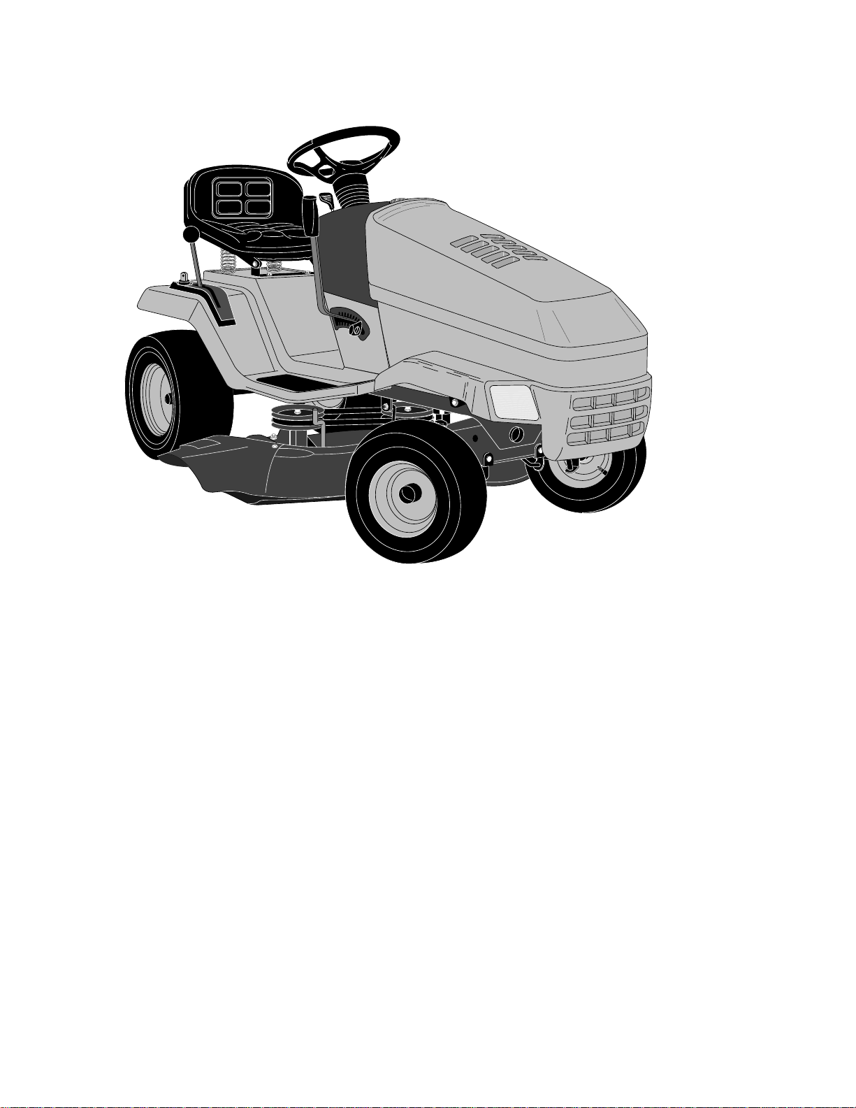
CONGRATULATIONS on your purchase of a new Tractor. It has been designed, engineered and manufactured to give you the
best possible dependability and performance.
Should you experience any problem you cannot easily remedy, please contact your nearest authorized service facility. We have
competent, well-trained technicians and the proper tools to service or repair this unit.
Please read and retain this manual. The instructions will enable you to assemble and maintain your unit properly. Always observe
the “SAFETY RULES”.
INTERNATIONAL SYMBOLS
These symbols may appear on your unit or in the literature supplied with the product. Learn and understand their meaning.
BATTERY CAUTION REVERSE FORWARD FAST SLOW
ENGINE ON ENGINE OFF OIL PRESSURE CLUTCH LIGHTS ON LIGHTS OFF
FUEL CHOKE MOWER HEIGHT DIFFERENTIAL
LOCK
LOCKED UNLOCKED
P
REVERSE NEUTRAL HIGH LOW
ATTACHMENT
CLUTCH ENGAGEDMOWER LIFT
NOTE: The illustrations shown in this manual are to aid in the assembly and operation of your tractor. They may or may not show the
actual model you have purchased.
WARNING: This unit is equipped with an internal combustion engine and should not be used on or near any unimproved forest-covered,
brush-covered or grass-covered land unless the engine's exhaust system is equipped with a spark arrester meeting applicable local or
state laws (if any). If a spark arrester is used, it should be maintained in effective working order by the operator.
In the state of California the above is required by law (Section 4442 of the California Public Resources Code). Other states may have similar
laws. Federal laws apply on federal lands. A spark arrester for the muffler is available through your nearest authorized service facility.
ATTACHMENT
CLUTCH DISENGAGED
PARKING BRAKE
IGNITION
TABLE OF CONTENTS
SAFETY RULES ............................................................2
ASSEMBLY.................................................................5-7
OPERATION.............................................................8-11
CUSTOMER RESPONSIBILITIES..........................12-14
SERVICE AND ADJUSTMENTS ............................15-19
STORAGE.................................................................... 20
TROUBLE SHOOTING ...........................................21-22
SCHEMATIC................................................................ 23
REPAIR PARTS......................................................24-42
WARRANTY............................................................46-47
3
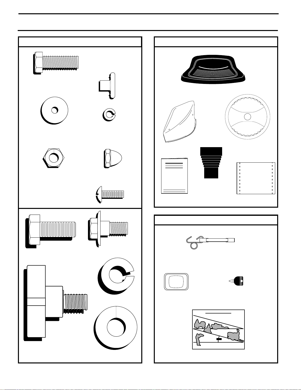
CONTENTS OF HARDWARE PACK
Parts Bag contents shown full size
(2) Hex Bolts
5/16-18 x 1
(2) Weld Nuts #10
(2) Washers
3/16 x 3/4 x 16 Gauge
(2) Acorn
5/16-18
(2) Locknuts
5/16-18
(2) Screws #10 x 5/8
(2) Lock
Washers #10
Nuts
Parts packed separately in carton
Seat
Mulcher
Plate
Steering Wheel
Steering
Sleeve
Manual
Parts Bag
(1) Hex Bolt 1/2-13 x 1
(1) Lock
Washer 1/2
(1) Knob with
Flat Washer
(if Equipped)
(1) Washer 17/32 x 1-3/16 x 12 Gauge
(1) Shoulder
Bolt 5/16-18
Parts bag contents not shown full size
(2) Latch Hook
Assemblies
Steering
Wheel
Insert
Slope Sheet
(2) Keys
4
ASSEMBLY
TOOLS REQUIRED FOR ASSEMBLY
A socket wrench set will make assembly easier. Standard
wrench sizes are listed.
(1) 9/16" wrench Pliers
(1) 3/4" wrench Tire pressure gauge
(2) 1/2" wrenches Phillips Screwdriver
Utility knife
When right and left hand are mentioned in this manual, it
means when you are in the operating position (seated
behind the steering wheel).
TO REMOVE TRACTOR FROM CART ON
UNPACK CARTON
• Remove all accessible loose parts and parts cartons
from carton (See page 4).
• Cut from top to bottom, along lines on all four corners
of carton and lay panels flat.
• Check for any additional loose parts or cartons and
remove.
BEFORE ROLLING TRACTOR OFF SKID
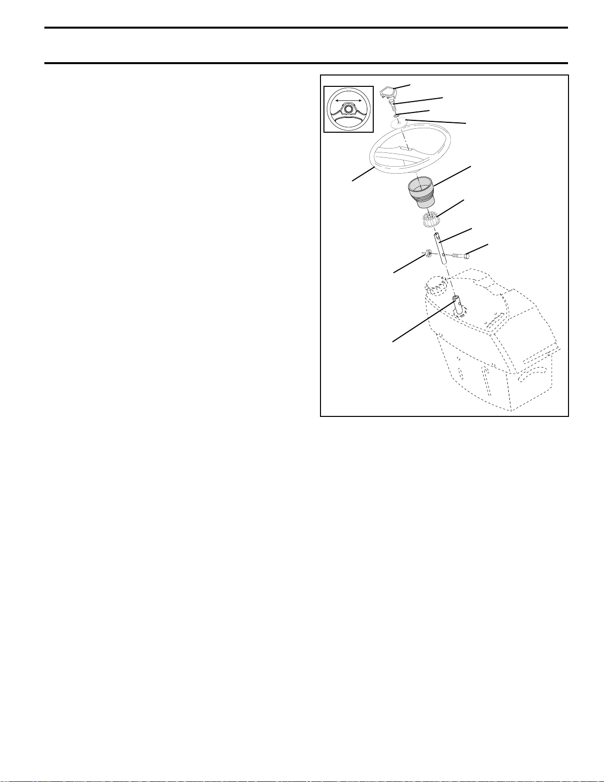
ASSEMBLE EXTENSION SHAFT
• Slide extension shaft onto lower steering shaft. Align
mounting holes in extension and lower shafts and
install 5/16 hex bolt and locknut. Tighten securely.
IMPORTANT: TIGHTEN BOLT AND NUT SECURELY TO
18-22 FT. LBS TORQUE.
INSTALL STEERING WHEEL
• Position front wheels of the tractor so they are pointing
straight forward.
• Slide steering wheel adapter onto steering shaft extension.
• Position steering wheel so cross bars are horizontal
(left to right) and slide onto adapter.
• Assemble large flat washer, 3/8 lock washer, 3/8 hex
bolt and tighten securely.
• Snap steering wheel insert into center of steering
wheel.
• Remove protective materials from tractor hood and
grill.
IMPORTANT: CHECK FOR AND REMOVE ANY STAPLES
IN SKID THAT MAY PUNCTURE TIRES WHERE TRACTOR
IS TO ROLL OFF SKID.
INSERT
3/8 HEX BOLT
3/8 LOCK WASHER
LARGE FLAT
WASHER
STEERING
SLEEVE
STEERING
WHEEL
5/16 LOCKNUT
LOWER
STEERING
SHAFT
ADAPTER
EXTENSION SHAFT
5/16 HEX BOLT
FIG. 1
TO ROLL TRACTOR OFF SKID (See Operation section for location of controls)
• Press lift lever plunger and raise attachment lift lever to
its highest position.
• Release parking brake by depressing clutch/brake
pedal.
• Place gearshift lever in neutral (N) position.
• Roll tractor forward off skid.
• Remove banding holding discharge guard up against
tractor.
5
ASSEMBLY
HOW TO SET UP YOUR TRACTOR
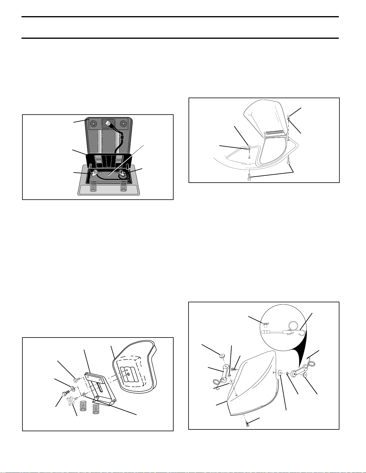
CHECK BATTERY (See Fig. 2)
• Lift seat pan to raised position and open battery box
door.
• If this battery is put into service after month and year
indicated on label (label located between terminals)
charge battery for minimum of one hour at 6-10 amps.
(See "BATTERY" in CUSTOMER RESPONSIBILITIES
section of this manual for charging instructions).
SEAT PAN
LABEL
BATTERY
BOX DOOR
TERMINAL
FIG. 2
INSTALL SEAT (See Fig. 3)
Adjust seat before tightening adjustment bolt or optional
knob.
• Remove cardboard packing on seat pan.
• Place seat on pan and assemble shoulder bolt.
• Assemble loosely adjustment bolt, lock washer and flat
washer (or knob, if so equipped). Do not tighten.
• Tighten shoulder bolt securely.
• Lower seat into operating position and sit on seat.
• Slide seat until a comfortable position is reached which
allows you to press clutch/brake pedal all the way down
(See Fig. 6).
• Get off seat without moving its adjusted position.
• Raise seat and tighten adjustment bolt or knob securely.
SEAT PAN
SHOULDER
BOLT
LOCK
WASHER
SEAT
TERMINAL
TO INSTALL MULCHER PLATE
PREPARE MOWER DECK (See Fig. 4)
• Using holes provided in mower deck, install 5/16-18x1
hex bolts, 5/16-18 locknuts, and 5/16-18 acorn nuts.
• Install hex bolt from under mower deck and tighten
locknut securely. Assemble and tighten acorn nut on
hex bolt.
ACORN NUT
ACORN NUT
LOCKNUT
LOCKNUT
HEX BOLT
FIG. 4
INSTALL MULCHER PLATE (See Figs. 5 and 6)
• Install two latch hooks to mulcher plate using screw,
washer, lock washer, and weld nut as shown.
NOTE: Pre-assemble weld nut to latch hook by inserting
weld nut from the top with hook pointing down.
• Tighten hardware securely.
• Raise and hold deflector shield in upright position.
• Place front of mulcher plate over front of mower deck
opening and slide into place, as shown.
• Hook front latch hook onto hex bolt on front of mower
deck.
• Hook rear latch hook onto hex bolt on back of mower
deck.
WELD
NUT
LATCH
HOOK
WELD NUT
FROM THE TOP
LOCK
WASHER
SCREW
HOOK
POINTS
DOWN
LATCH
HOOK
ADJUSTMENT
BOLT
KNOB
(IF SO EQUPPED)
FIG. 3
FLAT
WASHER
6
WASHER
MULCHER
PLATE
SCREW
FIG. 5
LOCK
WASHER
WASHER
WELD
NUT
ASSEMBLY
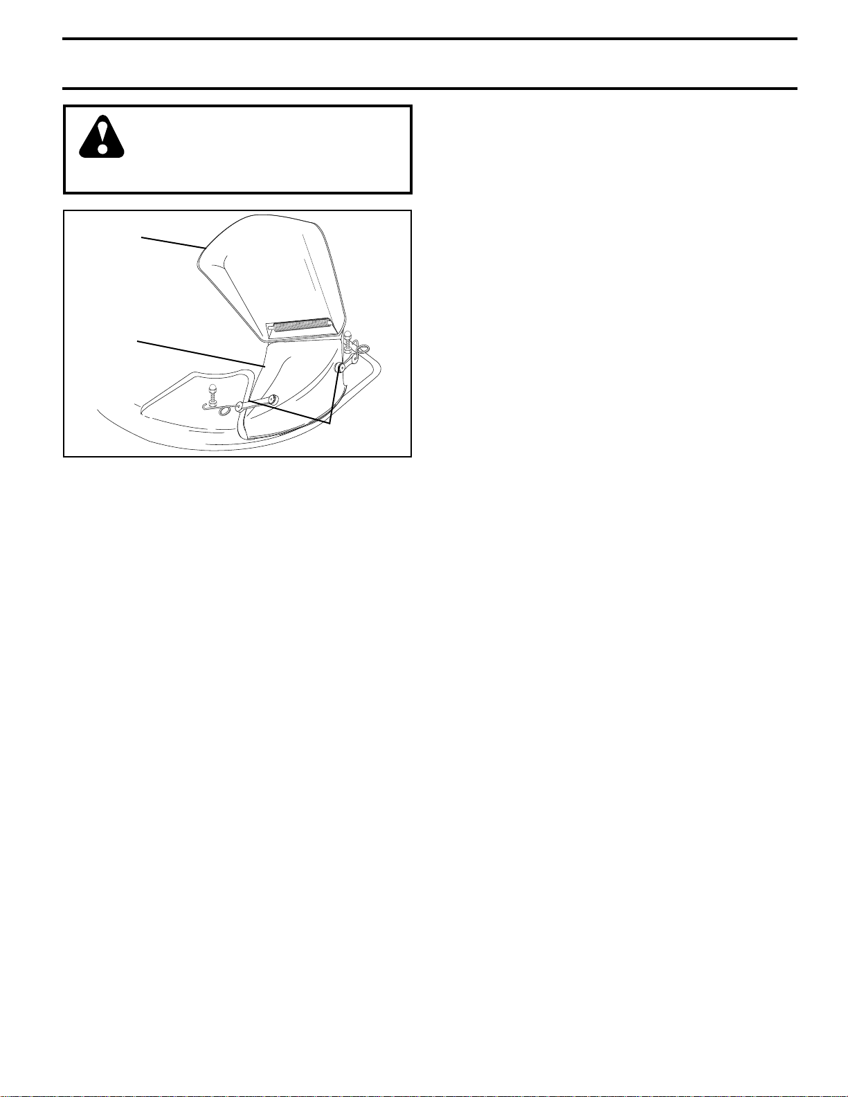
CAUTION: Do not remove discharge
guard from mower. Raise and hold
guard when attaching mulcher plate
and allow it to rest on plate while in
operation.
DEFLECTOR
SHIELD
MULCHER
PLATE
LATCH
HOOKS
FIG. 6
TO CONVERT TO BAGGING OR
DISCHARGING
Simply remove mulcher plate and store in a safe place.
Your mower is now ready for discharging or installation of
optional grass catcher accessory.
NOTE: It is not necessary to change blades. The mulcher
blades are designed for discharging and bagging also.
✓
CHECKLIST
BEFORE YOU OPERATE AND ENJOY YOUR NEW
TRACTOR, WE WISH TO ASSURE THAT YOU RECEIVE
THE BEST PERFORMANCE AND SATISFACTION FROM
THIS QUALITY PRODUCT.
PLEASE REVIEW THE FOLLOWING CHECKLIST:
✓ All assembly instructions have been completed.
✓ No remaining loose parts in carton.
✓ Battery is properly prepared and charged. (Minimum
1 hour at 6 amps).
✓ Seat is adjusted comfortably and tightened securely.
✓ All tires are properly inflated. (For shipping purposes,
the tires were overinflated at the factory).
✓ Be sure mower deck is properly leveled side-to-side/
front-to-rear for best cutting results. (Tires must be
properly inflated for leveling).
✓ Check mower and drive belts. Be sure they are routed
properly around pulleys and inside all belt keepers.
✓ Check wiring. See that all connections are still secure
and wires are properly clamped.
WHILE LEARNING HOW TO USE YOUR TRACTOR, PAY
EXTRA ATTENTION TO THE FOLLOWING IMPORTANT
ITEMS:
✓ Engine oil is at proper level.
✓ Fuel tank is filled with fresh, clean, regular unleaded
gasoline.
✓ Become familiar with all controls - their location and
function. Operate them before you start the engine.
✓ Be sure brake system is in safe operating condition.
CHECK TIRE PRESSURE
The tires on your tractor were overinflated at the factory for
shipping purposes. Correct tire pressure is important for
best cutting performance.
• Reduce tire pressure to 14 PSI in front tires and 12 PSI
in rear tires.
CHECK DECK LEVELNESS
For best cutting results, mower housing should be properly
leveled. See “TO LEVEL MOWER HOUSING” in the
Service and Adjustments section of this manual.
CHECK FOR PROPER POSITION OF ALL
BELTS
See the figures that are shown for replacing motion and
mower blade drive belts in the Service and Adjustments
section of this manual. Verify that the belts are routed
correctly.
CHECK BRAKE SYSTEM
After you learn how to operate your tractor, check to see
that the brake is properly adjusted. See “TO ADJUST
BRAKE” in the Service and Adjustments section of this
manual.
7
OPERATION
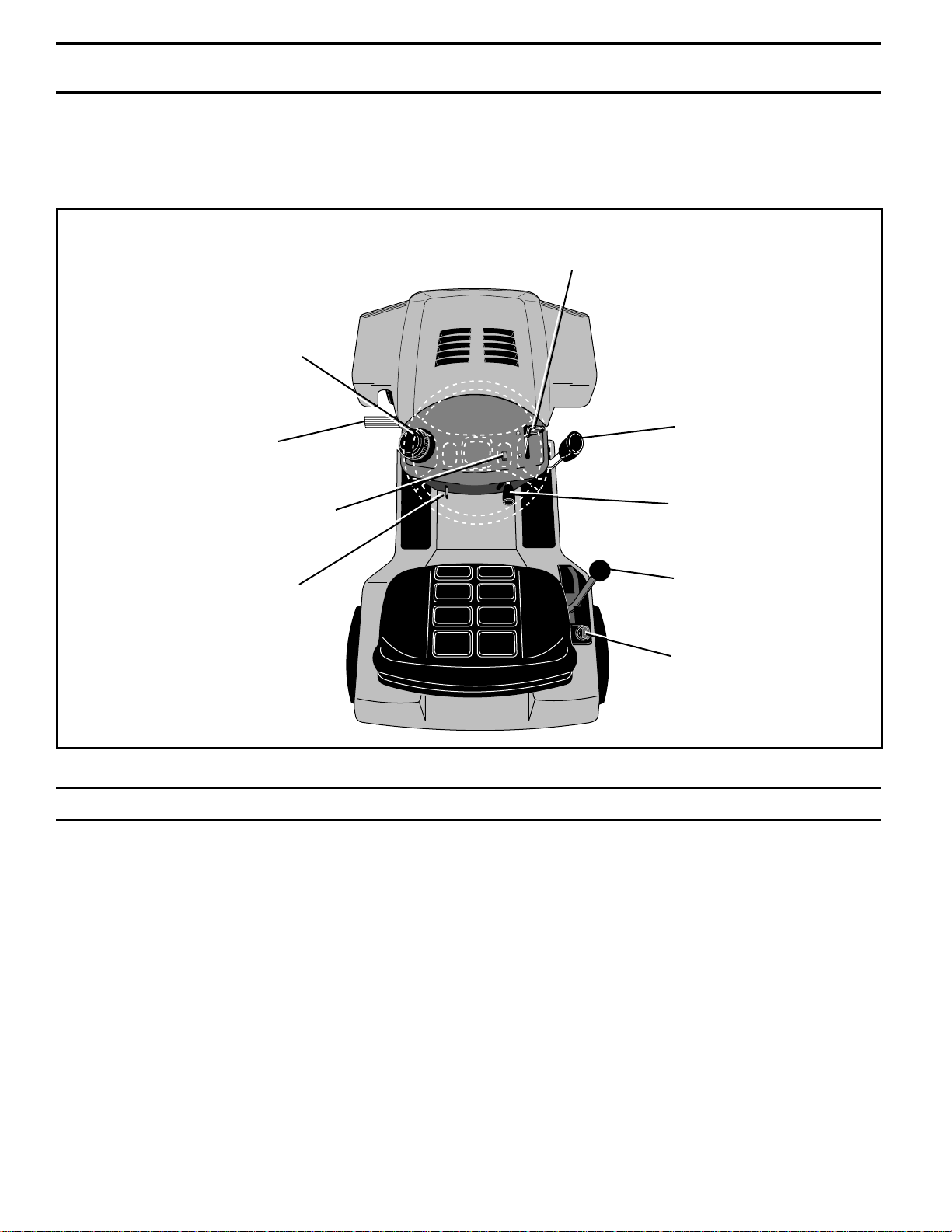
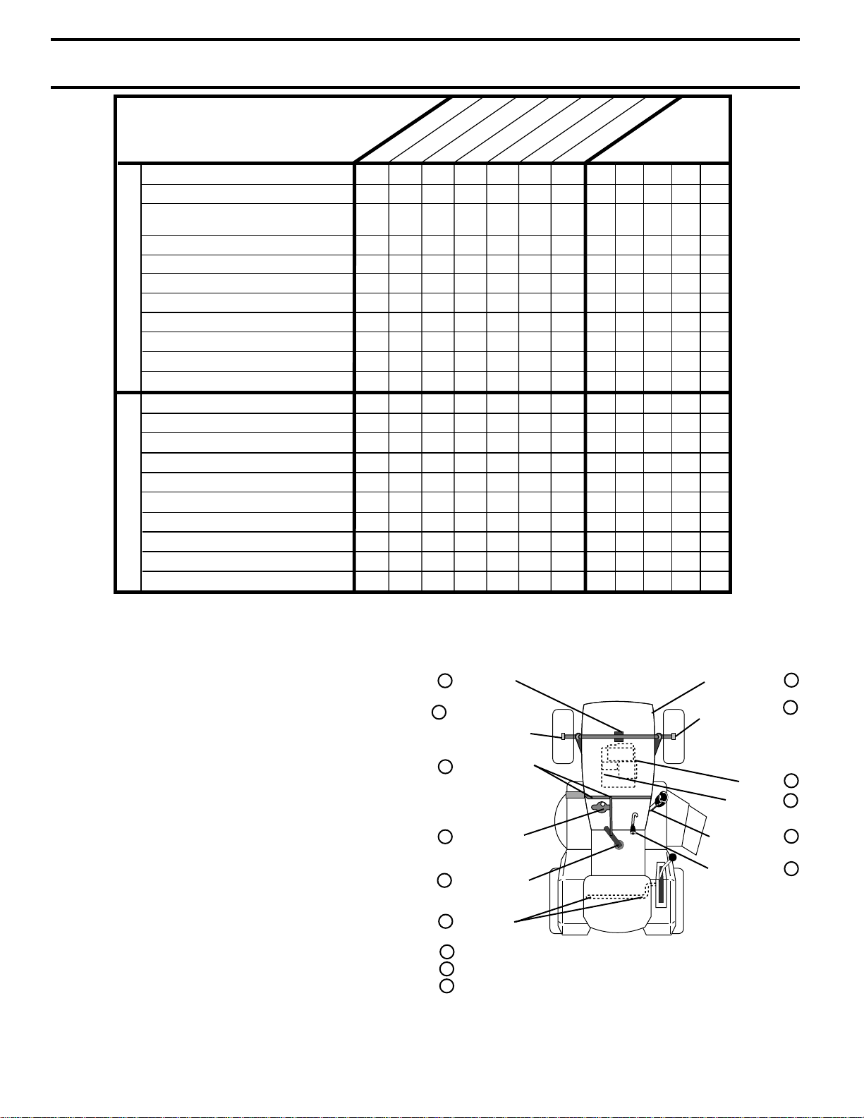
KNOW YOUR TRACTOR
READ THIS OWNER'S MANUAL AND SAFETY RULES BEFORE OPERATING YOUR TRACTOR.
Compare the illustrations with your Tractor to familiarize yourself with the location of various controls and adjustments. Save
this manual for future reference.
THROTTLE/CHOKE CONTROL
FUEL CAP
MOWER LIFT
CLUTCH/BRAKE PEDAL
LEVER
LIGHT SWITCH
(IF SO EQUIPPED)
PARKING BRAKE LEVER
Your tractor conforms to the safety standards of the American National Standards Institute.
IGNITION SWITCH: Used for starting and stopping the
engine.
THROTTLE/CHOKE CONTROL: Used for starting and
controlling engine speed.
CLUTCH/BRAKE PEDAL: Used for declutching and braking the lawn rider and starting the engine.
GEARSHIFT LEVER: Selects the speed and direction of
the lawn rider.
ATTACHMENT CLUTCH
LEVER
GEAR SHIFT
LEVER
IGNITION SWITCH
FIG. 8
LIGHT SWITCH: (If so equipped) Turns headlights on or
off.
PARKING BRAKE LEVER: Locks clutch/brake pedal into
the brake position.
ATTACHMENT CLUTCH LEVER: Used to engage the
mower blades.
MOWER LIFT LEVER: Used to raise and lower the mower
deck.
8
OPERATION
WEAR YOUR
SAFETY GLASSES
FORESIGHT IS BETTER
THAN NO SIGHT
The operation of any tractor can result in foreign objects thrown into the eyes, which can result
in severe eye damage. Always wear safety glasses or eye shields before starting your tractor
and while moving. We recommend a wide vision safety mask over spectacles or standard safety
glasses.
HOW TO USE YOUR TRACTOR
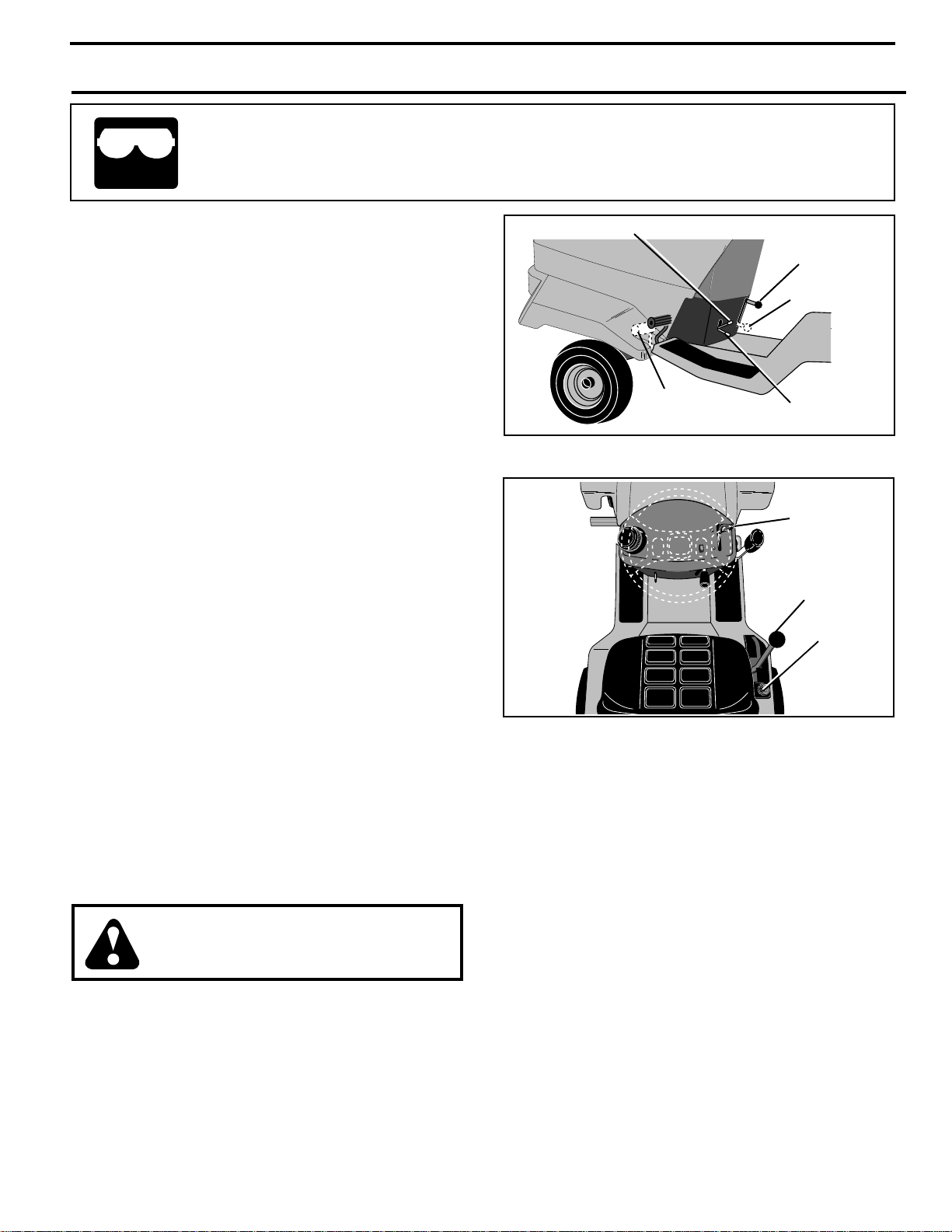
TO SET PARKING BRAKE (See Fig.9)
Your tractor is equipped with an operator presence sensing
switch. When engine is running, any attempt by the
operator to leave the seat without first setting the parking
brake will shut off the engine.
• Depress clutch/brake pedal into full “BRAKE” position
and hold.
• Place parking brake lever in “ENGAGED” position and
release pressure from clutch/brake pedal. Pedal should
remain in “BRAKE” position. Make sure parking brake
will hold tractor secure.
STOPPING (See Fig. 9 and 10)
MOWER BLADES -
• To stop mower blades,move attachment clutch lever to
“DISENGAGED” position.
GROUND DRIVE -
• To stop ground drive, depress clutch/brake pedal into
full “BRAKE” position.
• Move gearshift lever to neutral (N) position.
ENGINE -
• Move throttle control to slow position.
NOTE: Failure to move throttle control to slow position and
allowing engine to idle before stopping may cause engine
to “backfire”.
• Turn ignition key to “OFF” position and remove key.
Always remove key when leaving tractor to prevent
unauthorized use.
• Never use choke to stop engine.
IMPORTANT: LEAVING THE IGNITION SWITCH IN ANY
POSITION OTHER THAN "OFF" WILL CAUSE THE
BATTERY TO BE DISCHARGED, (DEAD).
NOTE: Under certain conditions when tractor is standing
idle with the engine running, hot engine exhaust gases may
cause “browning” of grass. To eliminate this possibility,
always stop engine when stopping tractor on grass areas.
CAUTION: Always stop tractor completely, as described above, before leaving the operator's position; to empty
grass catcher, etc.
TO USE THROTTLE CONTROL (See Fig. 10)
Always operate engine at full throttle.
• Operating engine at less than full throttle reduces the
battery charging rate.
• Full throttle offers the best bagging and mower performance.
TO MOVE FORWARD AND BACKWARD
(See Figs. 9 and 10)
The direction and speed of movement is controlled by the
gearshift lever.
PARKING BRAKE “ENGAGED”
ATTACHMENT
CLUTCH
LEVER “ENGAGED”
“DISENGAGED”
CLUTCH/BRAKE
PEDAL “BRAKE”
POSITION
“DISENGAGED”
FIG. 9
THROTTLE/
CHOKE
CONTROL
GEAR SHIFT
IGNITION
SWITCH
FIG. 10
• Start tractor with clutch/brake pedal depressed and
gearshift lever in neutral (N) position.
• Move gearshift lever to desired position.
• Slowly release clutch/brake pedal to start movement.
IMPORTANT: BRING TRACTOR TO A COMPLETE STOP
BEFORE SHIFTING OR CHANGING GEARS. FAILURE
TO DO SO WILL SHORTEN THE USEFUL LIFE OF YOUR
TRANSAXLE.
TO ADJUST MOWER CUTTING HEIGHT (See
Fig. 11)
The position of the attachment lift lever determines the
cutting height. The position of the attachment lift lever can
be adjusted by moving the height adjustment knob to
desired position.
• With lift lever back and locked in highest position, pull
out the adjustment knob and move to desired position.
• Move attachment lift lever out and forward to adjustment knob.
The cutting height range is approximately 1" to 3-1/2''. The
heights are measured from the ground to the blade tip with
the engine not running. These heights are approximate
and may vary depending upon soil conditions, height of
grass and types of grass being mowed.
9
OPERATION
• The average lawn should be cut to approximately 2-1/2
inches during the cool season and to over 3 inches
during hot months. For healthier and better looking
lawns, mow often and after moderate growth.
• For best cutting performance, grass over 6 inches in
height should be mowed twice. Make the first cut
relatively high; the second to desired height.•
The average lawn should be cut to approximately
2-1/2 inches during the cool season and to over 3
inches during hot months. For healthier and better
looking lawns, mow often and after moderate growth.
• For best cutting performance, grass over 6 inches in
height should be mowed twice. Make the first cut
relatively high; the second to desired height.
ATTACHEMENT
LIFT LEVER
ATTACHMENT
HEIGHT
6
3
2
1
ADJUSTMENT
KNOB
FIG. 11
TO OPERATE MOWER (See Figs. 11 and 12)
Your tractor is equipped with an operator presence sensing
switch. Any attempt by the operator to leave the seat with
the engine running and the attachment clutch engaged will
shut off the engine.
• Select desired height of cut.
• Start mower blades by engaging attachment clutch
control.
• TO STOP MOWER BLADES - disengage attachment
clutch control.
CAUTION: Do not operate the mower
without either the entire grass catcher,
on mowers so equipped, or the discharge guard in place.
ATTACHMENT
CLUTCH LEVER
“ENGAGED”
POSITION
ATTACHMENT
CLUTCH LEVER
“DISENGAGED”
POSITION
FIG. 12
TO OPERATE ON HILLS
CAUTION: Do not drive up or down
hills with slopes greater than 15° and
do not drive across any slope.
• Choose the slowest speed before starting up or down
hills.
• Avoid stopping or changing speed on hills.
• If slowing is necessary, move throttle control lever to
slower position.
• If stopping is absolutely necessary, push clutch/brake
pedal quickly to brake position and engage parking
brake.
• Move gearshift lever to 1st gear and be sure you have
allowed room for tractor to roll slightly as you restart
movement.
• To restart movement, slowly release parking brake and
clutch/brake pedal.
• Make all turns slowly.
TO TRANSPORT
• Raise attachment lift to highest position with attachment lift control.
• When pushing or towing your tractor, be sure gearshift
lever is in neutral (N) position.
• Do not push or tow tractor at more than five (5) MPH.
NOTE: To protect hood from damage when transporting
your tractor on a truck or a trailer, be sure hood is closed and
secured to tractor. Use an appropriate means of tying hood
to tractor (rope, cord, etc.).
BEFORE STARTING THE ENGINE
CHECK ENGINE OIL LEVEL
• The engine in your tractor has been shipped, from the
factory, already filled with summer weight oil.
• Check engine oil with tractor on level ground. See
engine manual for further instructions.
• For cold weather operation you should change oil for
easier starting (See engine manual).
• To change engine oil, see the Customer Responsibilities section in this manual.
ADD GASOLINE
• Fill fuel tank. Use fresh, clean, regular unleaded
gasoline with a minimum of 87 octane. (Use of leaded
gasoline will increase carbon and lead oxide deposits
and reduce valve life). Do not mix oil with gasoline.
Purchase fuel in quantities that can be used within 30
days to assure fuel freshness.
IMPORTANT: WHEN OPERATING IN TEMPERATURES
BELOW 32°F(0°C), USE FRESH, CLEAN WINTER GRADE
GASOLINE TO HELP INSURE GOOD COLD WEATHER
STARTING.
WARNING: Experience indicates that alcohol blended
fuels (called gasohol or using ethanol or methanol) can
attract moisture which leads to separation and formation of
acids during storage. Acidic gas can damage the fuel
system of an engine while in storage. To avoid engine
problems, the fuel system should be emptied before storage of 30 days or longer. Drain the gas tank, start the
engine and let it run until the fuel lines and carburetor are
empty. Use fresh fuel next season. See Storage Instructions for additional information. Never use engine or
carburetor cleaner products in the fuel tank or permanent
damage may occur.
CAUTION: Fill to bottom of gas tank
filler neck. Do not overfill. Wipe off any
spilled oil or fuel. Do not store, spill or
use gasoline near an open flame.
10
OPERATION
TO START ENGINE (See Fig. 8)
When starting the engine for the first time or if the engine
has run out of fuel, it will take extra cranking time to move
fuel from the tank to the engine.
• Sit on seat in operating position, depress clutch/brake
pedal and set parking brake.
• Place gear shift lever in neutral (N) position.
• Move attachment clutch to “DISENGAGED” position.
• Move throttle control to choke position.
NOTE: Before starting, read the warm and cold starting
procedures below.
• Insert key into ignition and turn key clockwise to “START”
position and release key as soon as engine starts. Do
not run starter continuously for more than fifteen seconds per minute. If the engine does not start after
several attempts, move throttle control to fast position,
wait a few minutes and try again. If engine still does not
start, move the throttle control back to the choke
position and retry.
WARM WEATHER STARTING (50° F and above)
• When engine starts, move the throttle control to the fast
position.
• The attachments and ground drive can now be used. If
the engine does not accept the load, restart the engine
and allow it to warm up for one minute using the choke
as described above.
COLD WEATHER STARTING ( 50° F and below)
• When engine starts, allow engine to run with the throttle
control in the choke position until the engine runs
roughly, then move throttle control to fast position. This
may require an engine warm-up period from several
seconds to several minutes, depending on the temperature.
• The attachments can also be used during the engine
warm-up period.
NOTE: If at a high altitude (above 3000 feet) or in cold
temperatures (below 32 F) the carburetor fuel mixture may
need to be adjusted for best engine performance. See “TO
ADJUST CARBURETOR” in the Service and Adjustments
section of this manual.
MOWING TIPS
• Mower should be properly leveled for best mowing
performance. See “TO LEVEL MOWER HOUSING”
in the Service and Adjustments section of this
manual.
• The left hand side of mower should be used for trimming.
• Drive so that clippings are discharged onto the area
that has been cut. Have the cut area to the right of
the machine. This will result in a more even distribution of clippings and more uniform cutting.
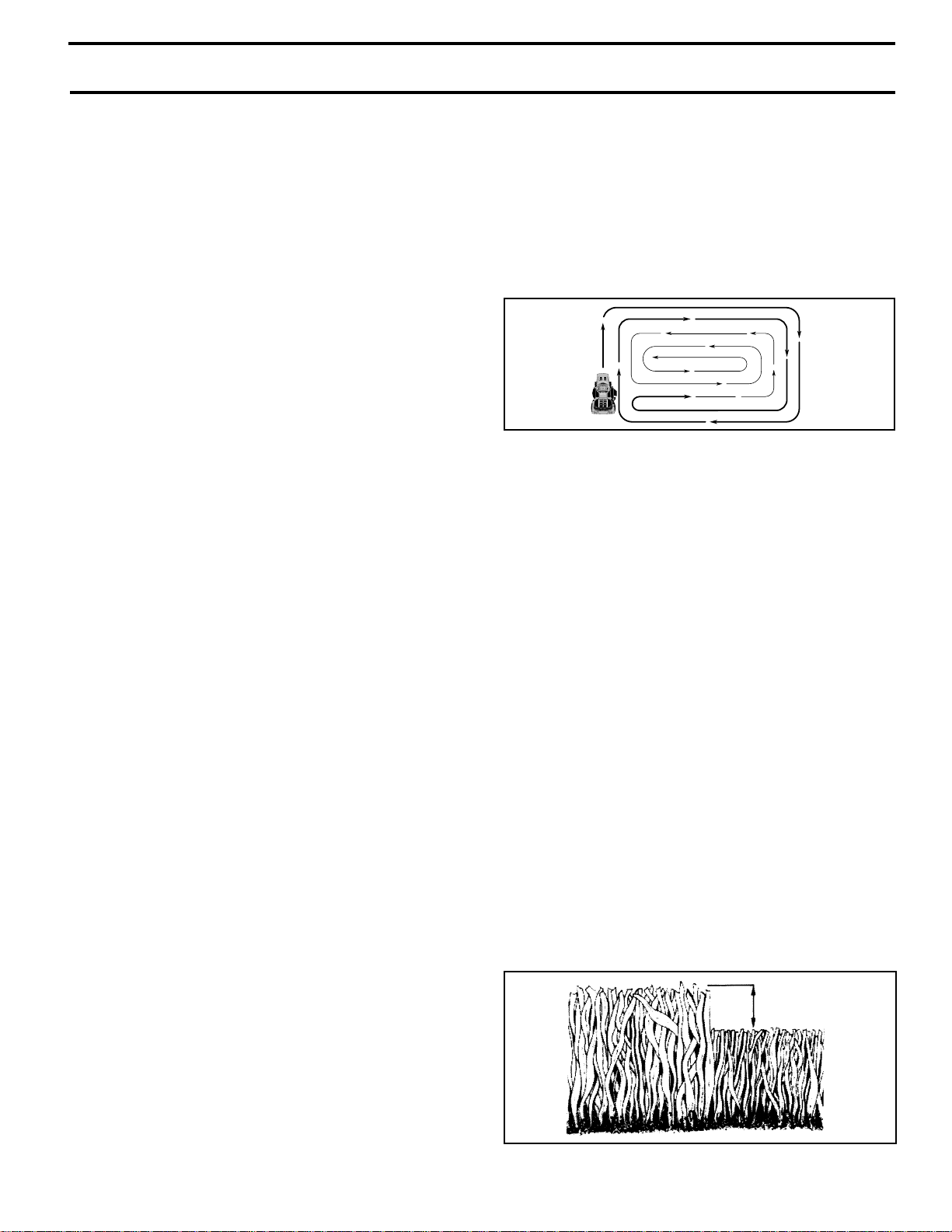
• When mowing large areas, start by turning to the
right so that clippings will discharge away from
shrubs, fences, driveways, etc. After one or two
rounds, mow in the opposite direction making left
hand turns until finished (See Fig. 13).
• If grass is extremely tall, it should be mowed twice
to reduce load and possible fire hazard from dried
clippings. Make first cut relatively high; the second
to the desired height.
• Do not mow grass when it is wet. Wet grass will
plug mower and leave undesirable clumps. Allow
grass to dry before mowing.
• Always operate engine at full throttle when mowing
to assure better mowing performance and proper discharge of material. Regulate ground speed by selecting a low enough gear to give the mower cutting
performance as well as the quality of cut desired.
• When operating attachments, select a ground speed
that will suit the terrain and give best performance of
the attachment being used.
THROTTLE
FIG. 13
MULCHING MOWING TIPS
IMPORTANT: FOR BEST PERFORMANCE, KEEP
MOWER HOUSING FREE OF BUILT-UP GRASS AND
TRASH. CLEAN AFTER EACH USE.
• The special mulching blade will recut the grass clippings many times and reduce them in size so that as
they fall onto the lawn they will disperse into the grass
and not be noticed. Also, the mulched grass will
biodegrade quickly to provide nutrients for the lawn.
Always mulch with your highest engine (blade) speed
as this will provide the best recutting action of the
blades.
• Avoid cutting your lawn when it is wet. Wet grass tends
to form clumps and interferes with the mulching action.
The best time to mow your lawn is the early afternoon.
At this time the grass has dried and the newly cut area
will not be exposed to the direct sun.
• For best results, adjust the mower cutting height so that
the mower cuts off only the top one-third of the grass
blades (See Fig. 14). For extremely heavy mulching,
reduce your width of cut on each pass and mow slowly.
• Certain types of grass and grass conditions may require that an area be mulched a second time to completely hide the clippings. When doing a second cut,
mow across or perpendicular to the first cut path.
• Change your cutting pattern from week to week. Mow
north to south one week then change to east to west the
next week. This will help prevent matting and graining
of the lawn.
MAX 1/3
FIG. 14
11
CUSTOMER RESPONSIBILITIES
MAINTENANCE SCHEDULE
FILL IN DATES
AS YOU COMPLETE
REGULAR SERVICE
Check Brake Operation
Check Tire Pressure
Check Operator Presence and
Interlock Systems
T
Check for Loose Fasteners
R
A
Sharpen/Replace Mower Blades
C
Lubrication Chart
T
Check Battery Level
0
Clean Battery and Terminals
R
Check Transaxle Cooling
Adjust Blade Belt(s) Tension
Adjust Motion Drive Belt(s) Tension
Check Engine Oil Level
Change Engine Oil
Clean Air Filter
E
Clean Air Screen
N
G
Inspect Muffler/Spark Arrester
I
Replace Oil Filter (If equipped)
N
Clean Engine Cooling Fins
E
Replace Spark Plug
Replace Air Filter Paper Cartridge
Replace Fuel Filter
1 - Change more often when operating under a heavy load or in high ambient temperatures.
2 - Service more often when operating in dirty or dusty conditions.
3 - If equipped with oil filter, change oil every 50 hours.
4 - Replace blades more often when mowing in sandy soil.
✔
✔
✔
✔
EVERY 8 HOURS
BEFORE EACH USE
EVERY 25 HOURS
✔✔
✔
4
✔
✔
6
✔
✔
✔
✔
✔
12,3,
1
2
✔
2
✔
✔
EVERY 50 HOURS
EVERY SEASON
EVERY 100 HOURS
7
✔
✔
SERVICE DATES
BEFORE STORAGE
✔
✔
✔
5
5
✔
✔
1,
2
✔
2
✔
✔
✔
2
✔
✔
5 - If equipped with adjustable system.
6 - Not required if equipped with maintenance-free battery.
7 - Tighten front axle pivot bolt to 35 ft.-lbs. maximum.
Do not overtighten.
GENERAL RECOMMENDATIONS
The warranty on this tractor does not cover items that have
been subjected to operator abuse or negligence. To
receive full value from the warranty, operator must maintain
tractor as instructed in this manual.
Some adjustments will need to be made periodically to
properly maintain your tractor.
All adjustments in the Service and Adjustments section of
this manual should be checked at least once each season.
• Once a year you should replace the spark plug, clean
or replace air filter, and check blades and belts for
wear. A new spark plug and clean air filter assure
proper air-fuel mixture and help your engine run better
and last longer.
BEFORE EACH USE
• Check engine oil level.
• Check brake operation.
• Check tire pressure.
• Check operator presence and
interlock systems for proper operation.
• Check for loose fasteners.
AXLE PIVOT
1
FRONT WHEEL
2
BEARING ZERK
(If equipped)
CLUTCH/BRAKE
1
PIVOT
ATTACHMENT
1
CLUTCH PIVOT
1
CLUTCH PIVOT
GEARSHIFT
1
PIVOTS
SAE 30 OR 10W30 MOTOR OIL
1
GENERAL PURPOSE GREASE
2
REFER TO CUSTOMER RESPONSIBILITIES“ENGINE” SECTION
3
IMPORTANT: DO NOT OIL OR GREASE THE PIVOT POINTS
WHICH HAVE SPECIAL NYLON BEARINGS. VISCOUS LUBRICANTS WILL ATTRACT DUST AND DIRT THAT WILL SHORTEN
THE LIFE OF THE SELF-LUBRICATING BEARINGS. IF YOU
FEEL THEY MUST BE LUBRICATED, USE ONLY A DRY, POWDERED GRAPHITE TYPE LUBRICANT SPARINGLY.
HOOD HINGES
FRONT WHEEL
BEARING ZERK
(If equipped)
THROTTLE
PLATE
ATTACHMENT
LIFT ARM PIVOT
ATTACHMENT
CLUTCH LEVER
12
LUBRICATION CHART
ENGINE
1
2
3
1
1
1
CUSTOMER RESPONSIBILITIES
TRACTOR
Always observe safety rules when performing any maintenance.
BRAKE OPERATION
If tractor requires more than six (6) feet stopping distance
at high speed in highest gear, then brake must be adjusted.
(See “TO ADJUST BRAKE” in the Service and Adjustments section of this manual).
TIRES
• Maintain proper air pressure in all tires - 14 PSI in front
tires and 12 PSI in rear tires.
• Keep tires free of gasoline, oil, or insect control chemicals which can harm rubber.
• Avoid stumps, stones, deep ruts, sharp objects and
other hazards that may cause tire damage.
NOTE: To seal tire punctures and prevent flat tires due to
slow leaks, tire sealant may be purchased from your local
parts dealer. Tire sealant also prevents tire dry rot and
corrosion.
OPERATOR PRESENCE SYSTEM
Be sure operator presence and interlock systems are
working properly. If your tractor does not function as
described, repair the problem immediately.
• The engine should not start unless the clutch/brake
pedal is fully depressed and attachement clutch control
is in the disengaged position.
• When the engine is running, any attempt by the operator to leave the seat without first setting the parking
brake should shut off the engine.
• When the engine is running and the attachment clutch
is engaged, any attempt by the operator to leave the
seat should shut off the engine.
• The attachment clutch should never operate unless the
operator is in the seat.
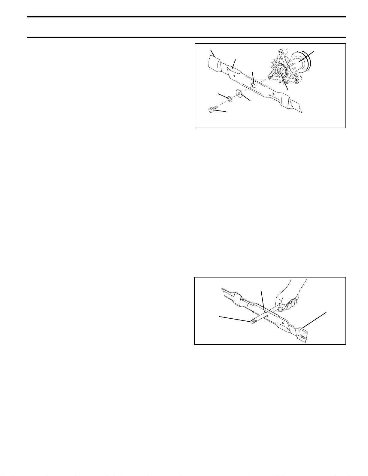
BLADE CARE
For best results mower blades must be kept sharp. Replace bent or damaged blades.
TRAILING EDGE UP
BLADE
LOCK
WASHER
HEX BOLT (GRADE 8)*
*A GRADE 8 HEAT TREATED BOLT CAN BE
IDENTIFIED BY SIX LINES ON THE BOLT HEAD.
CENTER
HOLE
STAR
FLAT WASHER
MANDREL
ASSEMBLY
FIG. 15
TO SHARPEN BLADE (See Fig. 16)
NOTE: We do not recommend sharpening blade - but if you
do, be sure the blade is balanced.
Care should be taken to keep the blade balanced. An
unbalanced blade will cause excessive vibration and eventual damage to mower and engine.
• The blade can be sharpened with a file or on a grinding
wheel. Do not attempt to sharpen while on the mower.
• To check blade balance, you will need a 5/8" diameter
steel bolt, pin, or a cone balancer. (When using a cone
balancer, follow the instructions supplied with balancer.)
NOTE: Do not use a nail for balancing blade. The lobes of
the center hole may appear to be centered, but are not.
• Slide blade on to an unthreaded portion of the steel bolt
or pin and hold the bolt or pin parallel with the ground.
If blade is balanced, it should remain in a horizontal
position. If either end of the blade moves downward,
sharpen the heavy end until the blade is balanced.
CENTER HOLE
5/8" BOLT
OR PIN
BLADE
BLADE REMOVAL (See Fig. 15)
• Raise mower to highest position to allow access to
blades.
• Remove hex bolt, lock washer and flat washer securing
blade.
• Install new or resharpened blade with trailing edge up
towards deck as shown.
IMPORTANT: TO ENSURE PROPER ASSEMBLY,
CENTER HOLE IN BLADE MUST ALIGN WITH STAR ON
MANDREL ASSEMBLY.
• Reassemble hex bolt, lock washer and flat washer in
exact order as shown.
• Tighten bolt securely (27-35 Ft. Lbs. torque).
IMPORTANT: BLADE BOLT IS GRADE 8 HEAT TREATED.
FIG. 16
BATTERY
Your tractor has a battery charging system which is sufficient for normal use. However, periodic charging of the
battery with an automotive charger will extend its life.
• Keep battery and terminals clean.
• Keep battery bolts tight.
• Keep small vent holes open.
• Recharge at 6-10 amperes for 1 hour.
TO CLEAN BATTERY AND TERMINALS
Corrosion and dirt on the battery and terminals can cause
the battery to “leak” power.
• Open battery box door.
13
CUSTOMER RESPONSIBILITIES
• Disconnect BLACK battery cable first then RED battery cable and remove battery from tractor.
• Rinse the battery with plain water and dry.
• Clean terminals and battery cable ends with wire brush
until bright.
• Coat terminals with grease or petroleum jelly.
• Reinstall battery (See “REPLACING BATTERY” in the
SERVICE AND ADJUSTMENTS section of this
manual).
V- BELTS
Check V-Belts for deterioration and wear after 100 hours.
Replace if necessary. The belts are not adjustable. Replace belts if they begin to slip from wear.
TRANSAXLE COOLING
Keep transaxle free from build-up of dirt and chaff which
can restrict cooling.
ENGINE
LUBRICATION
Change the oil after every 25 hours of operation or at least
once a year if the tractor is not used for 25 hours in one year.
Refer to engine manual.
SPARK PLUGS
Replace spark plugs at the beginning of each mowing
season or after every 100 hours of operation, whichever
occurs first. Spark plug type and gap setting are shown in
your engine manual.
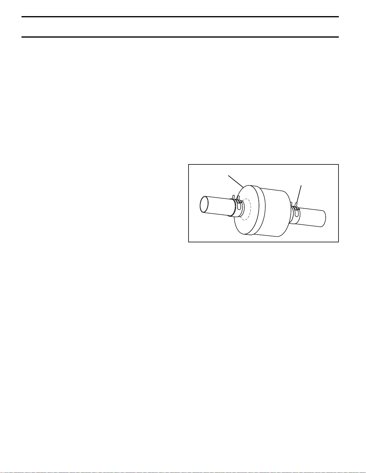
IN-LINE FUEL FILTER (See Fig. 17)
Fuel filter should be replaced once each season. If fuel filter
becomes clogged, obstructing fuel flow to carburetor, replacement is required.
• With engine cool, remove filter and plug fuel line
sections.
• Place new fuel filter in position in fuel line.
• Be sure there are no fuel line leaks and clamps are
properly positioned.
• Immediately wipe up any spilled gasoline.
FUEL FILTER
CLAMP
AIR FILTER
Your engine will not run properly and may be damaged by
using a dirty air filter. Remove cartridge every 25 hours and
tap gently to clean. Replace paper cartridge once a year or
after every 100 hours of operation, more often if used in
very dusty, dirty conditions.
• Remove knobs and cover.
• Remove cartridge nut and clean or replace cartridge.
• Reassemble and tighten securely.
NOTE: Do not attempt to oil the paper cartridge. See
engine manual.
CLEAN AIR SCREEN
Air screen must be kept free of dirt and chaff to prevent
engine damage from overheating. Clean with a wire brush
or compressed air to remove dirt and stubborn dried gum
fibers. See engine manual.
ENGINE COOLING FINS
Remove any dust, dirt or oil from engine cooling fins to
prevent engine damage from overheating. See engine
manual.
MUFFLER
Inspect and replace corroded muffler and spark arrester (if
equipped) as it could create a fire hazard and/or damage.
FIG. 17
CLEANING
• Clean engine, battery, seat, finish, etc. of all foreign
matter.
• Keep finished surfaces and wheels free of all gasoline,
oil, etc.
• Protect painted surfaces with automotive type wax.
We do not recommend using a garden hose to clean your
unit unless the electrical system, muffler, air filter and
carburetor are covered to keep water out. Water in engine
can result in a shortened engine life.
14
SER VICE AND ADJUSTMENTS
CAUTION: BEFORE PERFORMING ANY SERVICE OR ADJUSTMENTS:
• Depress clutch/brake pedal fully and set parking brake.
• Place gearshift lever in neutral (N) position.
• Place attachment clutch in “DISENGAGED” position.
• Turn ignition key “OFF” and remove key.
• Make sure the blades and all moving parts have completely stopped.
• Disconnect spark plug wire from spark plug and place wire where it cannot come in contact with
plug.
TO REMOVE MOWER (See Fig. 18)
Mower will be easier to remove from the right side of tractor.
• Park tractor on a level surface and engage parking
brake.
• Remove key from ignition.
• Be sure that attachment clutch lever is in “DISENGAGED” position.
• Lower mower deck to lowest cutting position.
• Remove retainer spring and washer that holds mower
clutch spring to the mower clutch arm.
• Disconnect mower clutch spring from mower clutch
arm.
• Remove retainer springs and washers from mower
stabilizer link.
• Remove retainer springs and washers from rear lift
links.
• Remove retainer spring and washer from front lift link.
• Withdraw front lift link, rear lift links and mower stabilizer link from brackets.
• Remove belt from engine pulley.
• Raise mower lift handle to transport position.
• Turn front tires to left.
• Slide mower deck out on right side of tractor.
TO INSTALL MOWER (See Fig. 18)
• Reverse removal instructions.
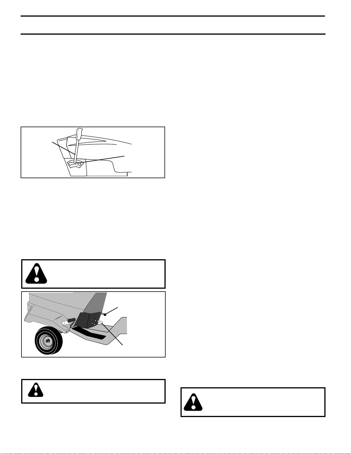
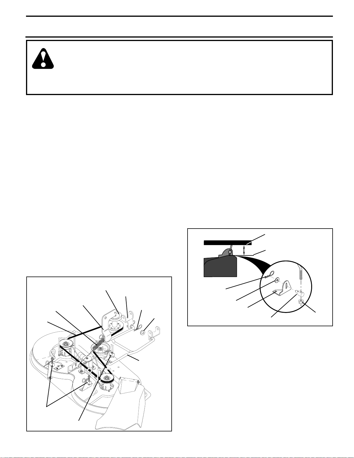
MOWER UPSTOP ADJUSTMENT (See Fig. 19)
• Raise attachment lift lever to highest (transport) position.
• Measure distance from top of mower deck to lower
flange of chassis (dim. “A”).
• Dim. “A” should be 3-3/8 to 3-1/2 inches.
• To adjust dim. “A”, if required, lower mower to lowest
position. Remove washer and retainer spring in trunnion, then withdraw trunnion pin from bracket. Loosen
trunnion locknut and rotate trunnion counterclockwise
on lift link to increase dim. “A” or clockwise on lift link to
decrease dim. “A”.
NOTE: Each full turn of trunnion will change dim. “A” by
1⁄16 inch.
• Tighten trunnion locknut.
• Re-insert trunnion into bracket with pin pointing to L.H.
side of tractor. Re-install washer and retainer spring.
• Raise lift lever to highest position and recheck dim. “A”.
Repeat adjustment if necessary.
LOWER FLANGE
OF CHASSIS
“A”
TOP OF MOWER DECK
MOWER
CLUTCH
SPRING
BELT
REAR LIFT
LINKS
MOWER
CLUTCH
ARM
FRONT LIFT LINK
ENGINE
PULLEY
FIG. 18
AXLE
BRACKET
RETAINER
SPRING
WASHER
MOWER
STABILIZER
LINK
15
RETAINER
SPRING
WASHER
BRACKET
FRONT LIFT TRUNNION
FIG. 19
TRUNNION
LOCKNUT
 Loading...