

Page 1
Introduction
OVERVIEW
Welcome to the Husky Hot Runner Design Center . This information is intended to simplify the hot runn er selection process.
Each section has been organized using easy to follow icon s.
Introduction
The primary hot runner system types offered by Husky are
identified within this section. Components that make up each
system are labeled for easy identification.
Nozzle Selection
This section guides the designer through the decisions and steps
for determining the gating method and nozzle size that best
satisfies the specific application.
Design Guidelines
In this section guidelines are offered to integrate Husky hot runner
systems into the mold.
Accessories
NOTE:
Sp are components and installation information are provided within
this section.
CAD Library
Mold designers are provided with all standard gating methods,
nozzles and generic hot runner view installations to be merged into
their CAD file. Available formats include:.dxf,.igs, and .prt.
Please refer to www.hotrunners.com for the most current design information.
2006.08
Please confirm all dimensions and nozzle/gating suitability with Husky prior to machining.
1
Page 2
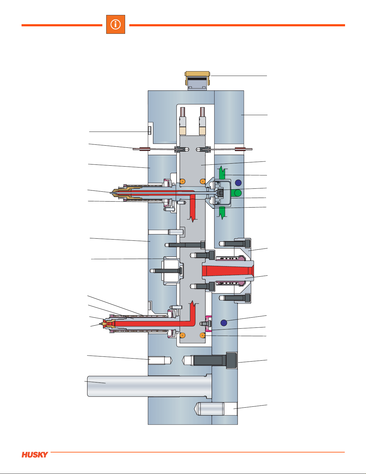
COMPLETE HOT RUNNER SYSTEM
Ultra 750 HT/VG Shown
Wire Clip
Manifold Thermocouple
Introduction
Electrical Connector
Backing Plate
Manifold Bushing
Valve Stem
UltraSeal
Manifold Plate
Center Locating
Insulator
Nozzle Heater
Nozzle Housing
Tip Retainer
Tip Insert
Manifold
Air Line
Piston
Cylinder
Backup Pad
Locating Ring
Sprue Bushin g
Plate Cooling
Backup Insulator Pad
Manifold Heater
Cavity Interface Tap
Guide Pin
Plate Bolt
Plate Alignment Dowel
Please confirm all dimensions and nozzle/gating suitability with Husky prior to machining.
2
2006.08
Page 3
Introduction
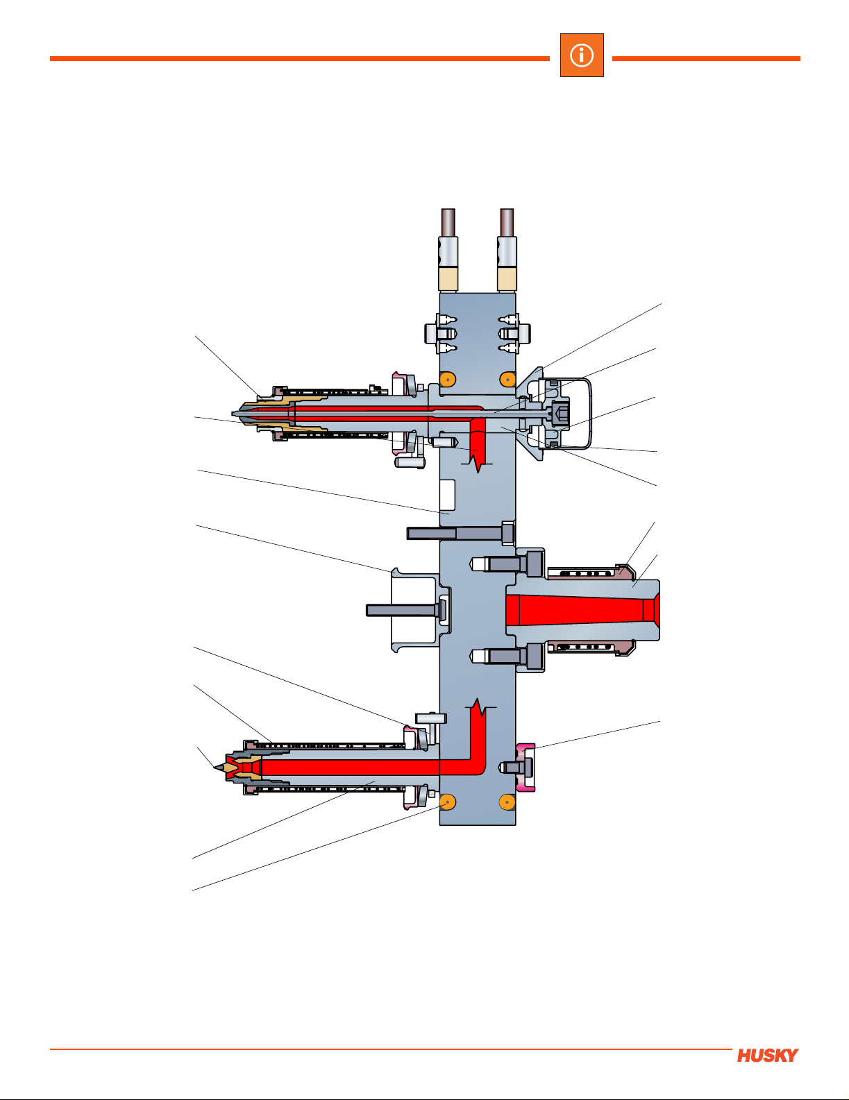
MANIFOLD SYSTEM
Ultra 750 HT/VG Shown
Nozzle Tip
Melt Channel
Backup Pad
Va lve Stem
Piston
Manifold
Center Insulator
UltraSeal
Nozzle Heater
Carbide Insert Tip
Piston Seal
Manifold Bushing
Sprue Heater
Sprue Bushin g
Backup Insulator Pad
2006.08
Nozzle Housing
Manifold Heater
Please confirm all dimensions and nozzle/gating suitability with Husky prior to machining.
3
Page 4

SINGLE CAVITY VALVE GATE SYSTEM
Ultra 750 SCVG Shown
Sprue Body Inser t
Introduction
Sprue Body Heater
Nozzle Heater
Nozzle Tip
Valve Stem
Locating Ring
Air Line
Tip Insulator
Please confirm all dimensions and nozzle/gating suitability with Husky prior to machining.
4
2006.08
Page 5

Introduction
HOT SPRUE
Ultra 750 HS Shown
Insulator Body
Nozzle Heater
Band Heater
Nozzle Tip Retainer
Nozzle Tip
Locating Ring
2006.08
Please confirm all dimensions and nozzle/gating suitability with Husky prior to machining.
5
Page 6

Introduction
INTRODUCTION
HOT RUNNER SYSTEMS
The objective of a hot runner system is to distribute the material from the machine nozzle to each gate, while minimizing
adverse effects to the material’s properties. Husky offers two hot runner system types:
• Complete hot runner system with plates
• Manifold system
Complete Hot Runner System
A complete hot runner system is supplied to the customer as a fully assembled unit, ready to be fastened to the cavity plate
and installed into the machine press.
Manifold System
A manifold system includes all components that make up the heated flow path except the hot runner plates. Drawings that
outline the necessary plate machining to accommodate the manifold and related components are include d with every
shipped manifold system.
Benefits of Ordering Complete Hot Runner System vs. Manifold System
Customer benefits when ordering a complete hot runner system:
• Husky's extensive design experience
• With a complete system, plate features such as: cooling circuits, air circuits, wire channels, and plate bolts are optimally positioned to maximize performanc e.
• 3-Year Leak-Proof Guarantee for UltraSeal
• Complete hot runner is ready to be fastened to the cavity plate and begin production.
• Simplified communication by providing one source responsibility.
™ systems.
Please confirm all dimensions and nozzle/gating suitability with Husky prior to machining.
6
2006.08
Page 7

Introduction
Single Drop Assemblies
Single drop assemblies are well-suited for single cavity molds and prototype applications. Two single drop system types
are available:
• Single Cavity Valve Gate (SCVG).
• Hot Sprue (HS).
SCVG
The SCVG is ideal for applications that require negligible gate vestige . R es in flow is mechanically regulated. Ultra 500,
Ultra 750 and Ultra 1000 SCVG’s are available for fast delivery.
HS
The HS is best suited for applications where a small gate mark is acceptable. Resin flow is thermally regulated. Ultra 500,
Ultra 750 and Ultra 1000 HS are available for fast delivery.
2006.08
Please confirm all dimensions and nozzle/gating suitability with Husky prior to machining.
7
Page 8

Introduction
TOLERANCE AND DIMENSION STANDARDS
All drawings within this section use imperial units of measurement. To simplify the drawing, the standard dimension
tolerancing, surface finishes, parallelism, and concentricity requirements are listed below and followed throughout the
manual. In situations where special tolerances or finishes are used, these are indicated on the drawing.
Tolerances
1 decimal place (.1)
2 decimal places (.01)
3 decimal places (.001)
4 decimal places (.0001)
Surface Finish
16µin
32µin
64µin
Definitions
To reduce the amount of text, the following symbols/abbreviations are used on the drawings:
Ø Full Diameter
Imperial
+/-.02
+/-.008
+/-.004
N/A
SR Spheric al Radius
BK-PLT Backing Plate
MF-PLT Manifold Plate
FR Full Radius
R, RAD Radius
B Nozzle Bore Depth
Gate Land
Sharp
XX Value
YY Value
T/C Thermocouple
G
Gate
> Minimum, greater than
< Maximum, less than
Contact Husky
Please confirm all dimensions and nozzle/gating suitability with Husky prior to machining.
8
2006.08
 Loading...