

Page 1

ETHERNET NETWORKING
Installation and Operations Manual
531906-3EN_A
GPS
Unit 1
Unit 2
Humminbird
ETHERNET
Page 2
THANK YOU!
hank you for choosing Humminbird®, the #1 name in marine electronics. Humminbird has built its reputation by designing and
T
anufacturing top quality, thoroughly reliable marine equipment. Your Humminbird is designed for trouble-free use in even the
m
arshest marine environment. We encourage you to read this manual carefully in order to get the full benefit from all the features
h
nd applications of your Humminbird product.
a
Contact Humminbird Customer Service at humminbird.com or call 1-800-633-1468.
WARNING! This device should not be used as a navigational
aid to prevent collision, grounding, boat damage, or
personal injury. When the boat is moving, water depth may
change too quickly to allow time for you to react. Always
perate the boat at very slow speeds if you suspect shallow
o
water or submerged objects.
WARNING! The electronic chart in your Humminbird unit is
an aid to navigation designed to facilitate the use of
authorized government charts, not to replace them. Only
official government charts and notices to mariners contain
all of the current information needed for the safety of
navigation, and the captain is responsible for their prudent
use.
WARNING! Disassembly and repair of this electronic unit
should only be performed by authorized service personnel.
Any modification of the serial number or attempt to repair
the original equipment or accessories by unauthorized
individuals will void the warranty.
WARNING! This product contains chemicals known to the
State of California to cause cancer and birth defects or
reproductive harm.
WARNING! Humminbird is not responsible for the loss of data
files (waypoints, routes, tracks, groups, recordings, etc.) that
may occur due to direct or indirect damage to the unit’s
hardware or software. It is important to back up your control
head’s data files periodically. Data files should also be saved
to your PC before restoring the unit’s defaults or updating
the software. See your Humminbird online account at
humminbird.com, the Waypoint Management Guide, and your
control head operations guide for details.
NOTE: Some features discussed in this manual require a
separate purchase, and some features are only available on
international models. Every effort has been made to clearly
identify those features. Please read the manual carefully in
rder to understand the full capabilities of your model.
o
NOTE: The Ethernet accessory is compatible with many
Humminbird models, and every effort has been made to note the
differences between the models and functions throughout this
manual. The illustrations in this manual may look different than
your display, but your model will operate in a similar way.
NOTE: To purchase accessories for your control head, visit our
Web site at humminbird.com or contact Humminbird Customer
Service at 1-800-633-1468.
NOTE: The procedures and features described in this manual are
subject to change without notice. This manual was written in
English and may have been translated to another language.
Humminbird is not responsible for incorrect translations or
discrepancies between documents.
NOTE: Product specifications and features are subject to change
without notice.
NOTE: Humminbird verifies maximum stated depth in saltwater
conditions, however actual depth performance may vary due to
transducer installation, water type, thermal layers, bottom
composition, and slope.
ROHS STATEMENT: Product designed and intended as a fixed
installation or part of a system in a vessel may be considered beyond
the scope of Directive 2002/95/EC of the European Parliament and of
the Council of 27 January 2003 on the restriction of the use of certain
hazardous substances in electrical and electronic equipment.
ATTENTION INTERNATIONAL CUSTOMERS: Products sold in the U.S.
are not intended for use in the international market. Humminbird
international units provide international features and are designed
to meet country and regional regulations. Languages, maps, time
zones, units of measurement, and warranty are examples of
features that are customized for Humminbird international units
purchased through our authorized international distributors.
To obtain a list of authorized international distributors, please visit
our Web site at humminbird.com or contact Humminbird Customer
Service at (334) 687-6613.
2
Page 3

ENVIRONMENTAL COMPLIANCE STATEMENT: It is the intention of Johnson Outdoors Marine Electronics, Inc. to be a responsible corporate citizen,
operating in compliance with known and applicable environmental regulations, and a good neighbor in the communities where we make or sell
our products.
WEEE DIRECTIVE: EU Directive 2002/96/EC “Waste of Electrical and Electronic Equipment Directive (WEEE)” impacts most distributors, sellers,
and manufacturers of consumer electronics in the European Union. The WEEE Directive requires the producer of consumer electronics to take
esponsibility for the management of waste from their products to achieve environmentally responsible disposal during the product life cycle.
r
WEEE compliance may not be required in your location for electrical & electronic equipment (EEE), nor may it be required for EEE designed and
intended as fixed or temporary installation in transportation vehicles such as automobiles, aircraft, and boats. In some European Union member
states, these vehicles are considered outside of the scope of the Directive, and EEE for those applications can be considered excluded from the
WEEE Directive requirement.
This symbol (WEEE wheelie bin) on product indicates the product must not be disposed of with other household refuse. It must be disposed
of and collected for recycling and recovery of waste EEE. Johnson Outdoors Marine Electronics, Inc. will mark all EEE products in accordance
with the WEEE Directive. It is our goal to comply in the collection, treatment, recovery, and environmentally sound disposal of those
products; however, these requirements do vary within European Union member states. For more information about where you should
ispose of your waste equipment for recycling and recovery and/or your European Union member state requirements, please contact your dealer
d
or distributor from which your product was purchased.
360 Imaging®, 700 Series™, 800 Series™, 900 Series™, 1100 Series™, Down Imaging®, DualBeam PLUS™, Fish ID+™, HELIX™, Humminbird®, InterLink™, RTS Window™,
Side Imaging®, SwitchFire®, WhiteLine™, and X-Press™ Menu are trademarked by or registered trademarks of Johnson Outdoors Marine Electronics, Inc.
© 2016 Johnson Outdoors Marine Electronics, Inc. All rights reserved.
345
Page 4

Page 5

TABLE OF CONTENTS
Introduction 7
1. Install an Ethernet Connection 8
2. Power On 12
Ethernet Network Overview 13
Customize the Unit Name 14
Open the Network Source Setup Dialog Box 15
Sonar Source Overview 17
Set up Sonar . . . . . . . . . . . . . . . . . . . . . . . . . . . . . . . . . . . . . . . . . . . .18
Select a Sonar Source . . . . . . . . . . . . . . . . . . . . . . . . . . . . . . . . . . .19
Change from a Lost Sonar Source . . . . . . . . . . . . . . . . . . . . . . . .22
Temperature Source Overview 23
Select a Temperature Source . . . . . . . . . . . . . . . . . . . . . . . . . . . . .23
Change from a Lost Temperature Source . . . . . . . . . . . . . . . . . .26
GPS Source and Sharing Waypoints Overview 28
Select a GPS Source . . . . . . . . . . . . . . . . . . . . . . . . . . . . . . . . . . . . .29
Change from a Lost GPS Source . . . . . . . . . . . . . . . . . . . . . . . . . .30
Share Waypoints . . . . . . . . . . . . . . . . . . . . . . . . . . . . . . . . . . . . . . .31
Restore Defaults (Setup Menu Tab) 32
Troubleshooting 33
Fishing System Doesn’t Power Up . . . . . . . . . . . . . . . . . . . . . . . . 33
Fishing System Defaults to Simulator
with a Transducer Attached . . . . . . . . . . . . . . . . . . . . . . . . . . . . . . 33
Contact Humminbird 34
Page 6

6
Page 7

INTRODUCTION
his manual will guide you through the following network setup instructions:
T
1. Connect two Humminbird units together
2. Power On
3. Configure your Humminbird Ethernet Network
4. Share Waypoints
Alarms, navigation, sonar data, and the menu system are all affected by the Ethernet network settings. We encourage
you to read this manual completely so that you may understand the full capabilities of your Humminbird Ethernet
network.
7
Introduction
Page 8

1. INSTALL AN ETHERNET CONNECTION
If your Humminbird control head has a built-in Ethernet connector, the unit can be connected to the Ethernet network. When you
connect the units together, data is shared between the two units.
Before you start, please note that the Ethernet network installation has the following requirements:
pdate Software: Your model may require a software update to enable Ethernet. Log in to your account at humminbird.com
• U
to download the latest software update. For assistance, contact Customer Service.
• Install the control heads and sources (GPS, transducers, temp/speed accessories, etc.) for your Fishing System. See the
equipment installation guides for details.
• Purchase Ethernet Connection Cables (separate purchase required): Your network configuration and Ethernet port shape will
determine which Humminbird connection cables you will need to purchase.
Purchase Ethernet Cables and Equipment
1. Review the illustrations on the following pages. Find your control head models and locate the Ethernet port on each control
head.
The shape of the Ethernet port determines the cable(s) you need to purchase, as shown in the following table. The Ethernet
port will be round or shaped like an hourglass.
Ethernet Cable Information
Control Heads Required Cables
(2) Units with Hourglass-shaped Ethernet Ports (2) AS EC QDE & (1) AS EC [length]E
(1) Unit with an Hourglass-Shaped Port and (1) Unit
with a Round Ethernet Port
(2) Units with Round Ethernet Ports (1) AS EC [length]E
NOTE: The AS EC [length]E cable is available in a variety of lengths. To purchase the Ethernet Cables and extension cables, visit
our Web site at humminbird.com. To network more than two units, purchase the Humminbird AS ETH 5PXG.
(1) AS EC QDE & (1) AS EC [length]E
Installation
8
Page 9
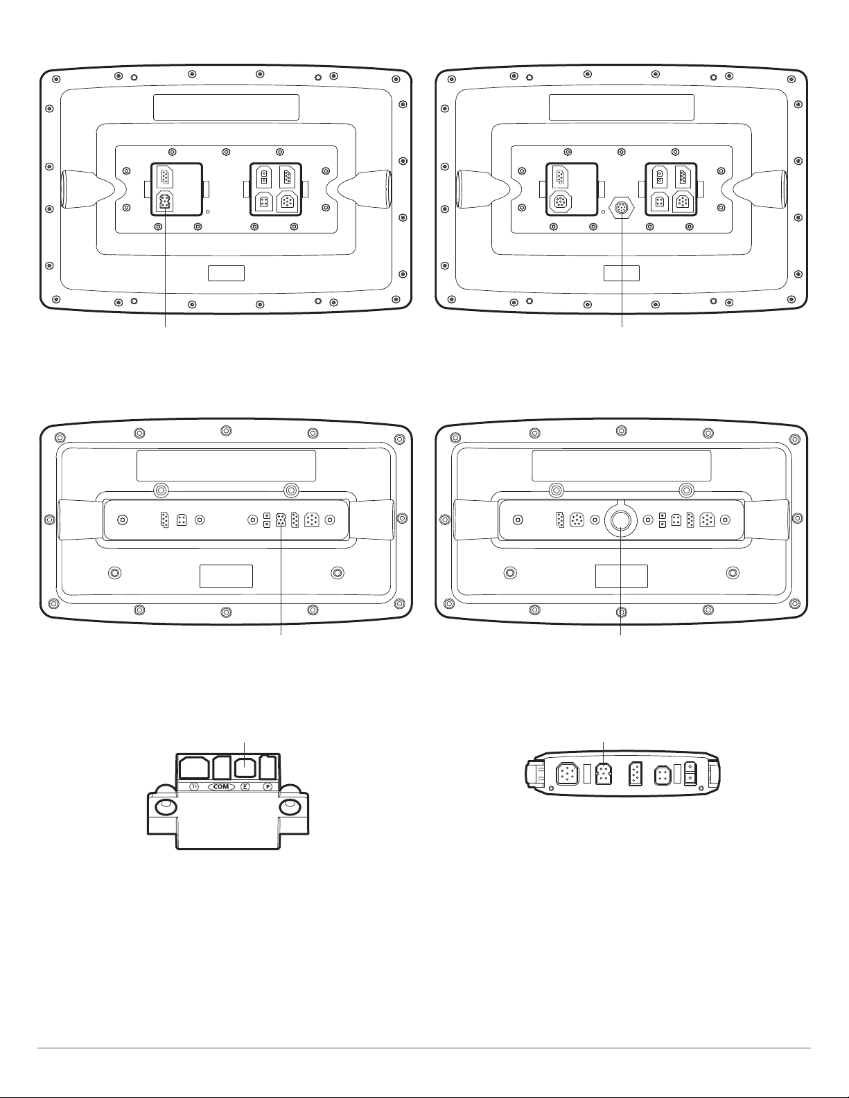
100ci Series HD Control Head with Hourglass-shaped Ethernet Port
1
100c Series Control Head with Round Ethernet Port
1
Ethernet port
800ci Series/900ci Series HD Control Head
with Hourglass-shaped Ethernet Port
Ethernet port
700 Series HD Cable Collector with
Hourglass-shaped Ethernet Port
Ethernet port
800c Series/900c Series Control Head with Round Ethernet Port
Ethernet port
HELIX 9, 10, 12 (Cable Tray) with
Hourglass-shaped Ethernet Port
Ethernet
Ethernet
9
Installation
Page 10
Connect the Control Heads
. Confirm that the control heads are powered off.
1
2. Review the illustrations on the preceding pages. Find your control head models and locate the Ethernet port on each control
head.
3. Connect the Ethernet cable(s) together and route them to each control head. Connect the Ethernet cable(s) to each Ethernet
port, noting the following:
• The connectors are keyed to prevent incorrect installation, so be careful not to force the connectors into the port.
• On round cable connectors, hand-tighten the screw nut to secure the connection.
• If the control head has a round Ethernet port, the Ethernet cable can be connected directly to the control head. If the control
head has an hourglass-shaped port, it will connect to the unit through a cable collector or cable tray. Consult your control
head installation guide for details.
CAUTION! Do NOT mount the cables where the connectors could be submerged in water or flooded. If cables are installed in a
splash-prone area, it may be helpful to apply dielectric grease to the inside of the connectors to prevent corrosion. Dielectric
grease can be purchased separately from a general hardware or automotive store.
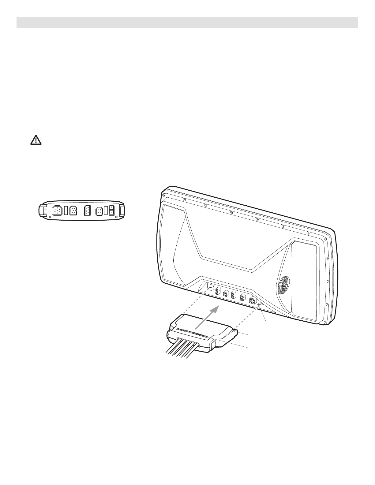
HELIX 9, 10, 12 (Cable Tray) with
Hourglass-shaped Ethernet Port
Ethernet
Connecting the Cable Tray to the Control Head (HELIX 9, 10, 12)
line up with pins
on cable tray
clasp
Humminbird
logo facing up
Installation
10
Page 11
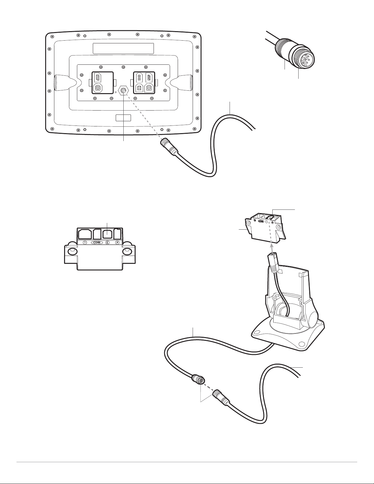
onnecting to a Round Ethernet Port
E
C
Ethernet port
Hand-Tightening the Screw Nut
screw nut
The connector is keyed to
prevent incorrect installation.
AS EC (length)E
700 Series HD Quick Disconnect
Mount Cable Collector
Ethernet
Connecting the Ethernet Cables to a 700 Series HD Unit
Ethernet port
Cable Collector
AS EC QDE Ethernet
Adapter Cable
AS EC(length)E
round
connectors
11
Installation
Page 12

2. POWER ON
hen you have installed an Ethernet network, the power on process is the same as powering on a single control head, however, your
W
ransducer connections will determine how the control head starts normal operation.
t
If there is a transducer connected to only one of the control heads, and you intend to share the transducer on the
network, power on the control head with the connected transducer first.
Power On
1. If there is a transducer connected to only one of the control heads, power it on first. Press the POWER/LIGHT key.
2. When you power on the control head, it will start Normal mode automatically if a functioning transducer is detected.
• If a transducer is not attached to the control head, but there is another transducer connected to the network, press the
MENU key when the Title screen is displayed. Select Normal from the Start-up Menu. (This step is only required for first-time
setup or after defaults have been restored on the unit.)
• If you are prompted to select a sonar source at start up, see Select a Sonar Source for more information.
3. Repeat steps 1 and 2 until all the control heads in the network are powered on.
NOTE: If you have an InterLink connected to the network, the Ethernet will disable the InterLink because both network systems
cannot be used at the same time.
Power On
12
Page 13

ETHERNET NETWORK OVERVIEW
hen the Humminbird network is installed, each control head automatically selects a primary source (transducer, temperature, and
W
PS). The control head selects the equipment connected to it as its primary source, but you can choose any compatible source on
G
he network.
t
For example, if you have more than one GPS receiver installed on the network, whether internal or external, you can select one GPS
receiver to be the shared source for all control heads on the network.
Local (default): The source is connected directly to the control head, and it is only reporting data to that control head.
Shared: The source is set up to send data to both control heads in the network, so they share the same information.
It is important to note that when a source is shared on the network, the source’s data will be synchronized between units. The
Menu System and View Rotation will change to match the shared source’s capabilities. Review each source section to
understand how a shared source will affect your control head.
CHIRP Models: A CHIRP unit can use sources from any other control heads on the network. If a unit is not CHIRP-capable, it
cannot use sources connected to the CHIRP control head (unless CHIRP mode is turned off). See Set up Sonar for details.
Example of a Network Configuration
speed
digital readout
Note that the Speed Digital Readout is the same on both control head views
GPS (Shared)
HELIX 9 SI GPS
788ci HD
Ethernet
speed
digital readout
Side Imaging Transducer Accessory (Local)
It will only report data to the HELIX 9 SI GPS.
13
DualBeam PLUS Transducer (Local)
It will only report data to the 788ci HD.
Overview
Page 14

CUSTOMIZE THE UNIT NAME
ach control head is assigned a unit name, which is based on its model number and serial number. Use the following instructions
E
o edit the unit name, so it is easier to identify each unit on the network.
t
1. Main Menu: Press the MENU key twice. Select the Network tab.
2. Select Unit Name (700, 800, 900, 1100 Series) or the Name of the Unit (HELIX models). Press the RIGHT Cursor key.
unit name
3. Use the Cursor Control key to edit the name.
4. Follow the on-screen prompts to save your changes.
Changing the Unit Name
Customize the Unit Name
Move from Space to Space Select a Letter, Number, or Symbol
14
Save
Page 15

OPEN THE NETWORK SOURCE SETUP DIALOG BOX
he Network Source Setup dialog box displays all the sources connected to the network. The sources may be shared on the network
T
r operating locally with their connected control head.
o
Open the Network Source Setup Dialog Box
1. Main Menu: Press the MENU key twice. Select the Network tab.
2. Select Network Source Setup. Press the RIGHT Cursor key.
Status Tab: Review the status tab to see all detected sources in the network. If a source is grayed out, the source is detected,
but the connection is lost or unavailable.
Select a Source: Review each source section in this manual to select a data source for each control head and understand how
a shared source will affect your control head.
CHIRP Models: A CHIRP unit can use sources from any other control heads on the network. If a unit is not CHIRP-capable, it
cannot use sources connected to the CHIRP control head (unless CHIRP Mode is turned off). See Set up Sonar for details.
Network Source Setup Dialog Box (700 Series HD)
status tab
temperature
sources from
transducers
and accessories
GPS source
source tabs
Grayed-out Source:
The transducer source
connection is lost.
If the Unit Name is
changed, the new name
will be displayed here. See
Customize the Unit Name.
source name
15
Open the Network Source Setup Dialog Box
Page 16

Network Source Setup Dialog Box (HELIX Series)
status tab
sonar sources
temperature sources
from transducers
and accessories
GPS source
source tabs
Grayed-out Source:
The transducer source
connection is lost.
If the Unit Name is
changed, the new name
will be displayed here. See
Customize the Unit Name.
source name
Open the Network Source Setup Dialog Box
16
Page 17

SONAR SOURCE OVERVIEW
hen you select a new transducer source, the alarms, menu settings, view rotation, and digital readouts will update automatically
W
n the control head.
o
• Menu Settings: If the sonar source is shared, the control heads will synchronize menu settings (Shared), while other menu
settings will continue to operate individually (Local) on each control head. When you change a shared menu setting on one
control head, it will be updated on the other control heads that are sharing the source.
• Views: The view rotation will update to display views that are compatible with the selected transducer.
• Alarms: When Sonar sources are shared on the network, the alarms are also shared. The shared alarm settings can be
controlled from either control head, and the alarms will display or sound on both control heads. To turn off a shared alarm, press
the EXIT key on any control head.
Shared Sonar Menu Settings
Beam Select Lower Range SI Range
Depth Alarm Max Depth SwitchFire
Depth Offset Noise Filter Water Type
Fish ID+ Ping Rate Units - Depth
Fish ID Sensitivity
Local Sonar Menu Settings
83 kHz Sensitivity Quad Layout Sonar Colors
455 kHz Sensitivity RTS Window Ping Rate
Bottom Lock Sensitivity (Down) SI Range
Bottom Range SI Colors SwitchFire
Bottom View SI Enhance Transducer Select
Chart Speed SI Sensitivity Upper Range
Depth Lines SI Side Water Type
NOTE: The Shared and Local menu options may change to accommodate new product features.
17
Sonar Sources
Page 18

Set up Sonar
se the instructions below to select sonar sources for each control head. Before you can select frequencies from the network, the
U
control heads must be set up with their connected transducer.
1. Set up the Transducer
The following instructions are only required the first time you set up each control head with an attached transducer.
1. Main Menu: Press the Menu key twice.
2. Select the Sonar tab > Connected Transducer (or Transducer Select).
3. Press the Right or Left Cursor keys to scroll through the compatible transducers for that model. Select the transducer that is
attached to the control head.
4. Repeat steps 1 to 3 for each control head.
If there is not a transducer attached to a control head, you can skip this section for that control head.
2. Turn on/off CHIRP Mode
A CHIRP unit can use sources from any other control head on the network. If a unit is not CHIRP-capable, it cannot use sources
connected to the CHIRP control head (unless CHIRP Mode is turned off).
1. Main Menu: Press the Menu key twice.
2. Select the Sonar tab > CHIRP Mode.
3. Select on or off.
In the following example, the HELIX 9 SI GPS Network Source Setup dialog box shows the HELIX 12 CHIRP SI GPS transducer is
listed, but it is grayed out to show it cannot be used by the HELIX 9 (because the HELIX 9 it is not CHIRP-capable). However, the
sonar source on the CHIRP unit will be available to the HELIX 9 if you turn off CHIRP mode on the HELIX 12.
Network Source Setup Dialog Box (HELIX 9 SI GPS)
sonar sources
grayed-out source
Sonar Sources
18
Page 19

Select a Sonar Source
hen you first set up the network, the control head will automatically choose the transducer connected to it. Use the Network Source
W
Setup dialog box to change the sonar source.
The transducer you select on the 2D tab will provide the data for the 2D Sonar Views and related digital readouts.
If you select a Down Imaging transducer on the Adv. tab, it will provide the data for the Down Imaging Views and related digital readouts.
If you select a Side Imaging transducer on the Adv. tab, it will provide the data for the Side Imaging Views and related digital readouts.
19
Sonar Sources
Page 20

s you select sonar sources for each view, it is important to consider the following information:
A
Default: When you first set up the network, the control head will automatically choose the transducer source connected to it.
You can use the default settings, or you can select which transducer you want to use.
ompatibility: If your 700, 800, 900, or 1100 Series model number ends in 8, your control head must be compatible with the
C
transducer you select on the network to use it as a sonar source. All other models can select any other transducer from the
etwork as a sonar source. However, if a model is not CHIRP-capable, it cannot network with other CHIRP units unless CHIRP
n
Mode is turned off on the CHIRP unit. See Set up Sonar for details.
Down Imaging Units: If you select a Down Imaging transducer on the network, you must choose the 2D beams (2D tab) and
the Down Imaging beams (Adv. tab) from the same Down Imaging transducer. The beams cannot be split in this scenario.
Accessories: If you have installed an accessory transducer, and it is not displayed in the transducer list, see Set up Sonar.
Select Sonar Sources
1. Open the Network Source Setup dialog box.
2. Select the 2D tab.
The 2D tab lists the beams available for the 2D Sonar Views.
3. Select: Press the DOWN or UP Cursor keys to choose a source.
4. Press the RIGHT Cursor key or the CHECK/INFO key to select it (check mark = selected).
5. Select the Adv. tab, and repeat steps 3 and 4.
The Advanced tab lists the Side Imaging and Down Imaging beams available for the Side Imaging and Down Imaging Views.
6. Save: Press the EXIT key twice to close the dialog box. Network settings are saved even after the unit is powered off.
7. Repeat the steps in this section on each control head to choose a sonar source.
Local Setup (default): To use separate transducers for each control head, repeat these steps on each control head until you’ve
set a transducer for each unit.
Shared Setup: To use the same transducer with more than one control head, repeat these steps on each control head and
select the same transducer for all units.
NOTE: It is not recommended to ping two transducers of the same frequency at the same time.
Sonar Sources
20
Page 21

available sonar
sources
Selecting Beams for the Side Imaging View (HELIX Series)
Scroll through the List Select
OR
Select
21
Sonar Sources
Page 22

Change from a Lost Sonar Source
f the control head cannot detect the selected transducer, follow the on-screen prompts to switch to another transducer in the
I
network. If you switch to a Local source, you are selecting the transducer connected directly to the control head.
Changing the Sonar Source (700 Series HD)
Changing the Sonar Source (HELIX Series)
Sonar Sources
22
Page 23

TEMPERATURE SOURCE OVERVIEW
hen you select a new temperature source, the alarms, menu settings, view rotation, and digital readouts will automatically update
W
n the control head.
o
• Menu Settings: If the temperature source is shared, the control heads will synchronize menu settings (Shared), while other
menu settings will continue to operate individually (Local) on each control head. When you change a shared menu setting on
one control head, it will be updated on the other control heads that are sharing the source.
• Views: The view rotation will update to display views or digital readouts that are compatible with the selected temperature source.
• Alarms: When temperature sources are shared on the network, the alarms are also shared. The shared alarm settings can be
controlled from either control head, and the alarms will display or sound on both control heads. To turn off a shared alarm, press
the EXIT key on each control head.
Shared Temperature Menu Settings
Temp. Alarm Units - Temp Aux. Temp Alarm
NOTE: The remaining temperature menu options are controlled locally. The Shared and Local menu options may change to
accommodate new product features.
Select a Temperature Source
Temperature sources can be detected from a transducer’s built-in temperature feature or from optional-purchase
temperature/speed accessories connected to the network.
• Default: When you first set up the network, the control head will automatically choose the temperature source connected to it.
• Temperature Tabs: The T1, T2, T3, and T4 tabs at the top of the Network Source Setup dialog box represent the digital readout
positions on the screen. You can choose a different temperature source for each digital readout box, so each control head can
display up to four temperature digital readouts on the display.
NOTE: There will be less than four temperature tabs displayed if there aren’t four temperature sources connected to the network.
Temperature Readout Sources
RIGHT or LEFT Cursor key
Press the
to select a tab.
available
temperature sources
temperature tabs
The Temperature Source tabs correspond with the digital readout
positions on the screen.
23
Temperature Sources
Page 24

Temperature Digital Readouts (1100 Series)
The Temperature Digital Readout positions correspond with the
T1, T2, T3, and T4 tabs in the Network Source Setup dialog box.
Select Temperature Sources
1. Open the Network Source Setup dialog box.
2. Select the tab for T1, T2, T3, or T4. Each tab represents a digital readout position on the screen.
NOTE: The temperature readout positions may vary with the Humminbird model. See the Views section and Select Readouts
section of your Humminbird Operations Manual for more information.
3. Select: Press the DOWN or UP Cursor keys to choose a source.
4. Press the RIGHT Cursor key or the CHECK/INFO key to select it (check mark = selected).
5. Repeat steps 2 through 4 to select a different temperature tab.
6. Save: Press the EXIT key twice to close the dialog box. Network settings are saved even after the unit is powered off.
7. Repeat the steps in this section on each control head to choose a temperature source for each tab. You can select the same
source or a different source.
Local Setup: To use separate temperature sources for each control head, repeat these steps on each control head until you’ve
set a temperature source for each unit and each digital readout.
Shared Setup: To use the same temperature sources on more than one control head, repeat these steps on each control head
and select the same temperature sources on all units.
Temperature Sources
24
Page 25

Temp 1 tab sets
the temperature source
for digital readout 1 on
the screen.
The control head detects
all the temperature
sources in the network.
Selecting a Temperature Source for Digital Readout Position 1
selected
unit name
column
(see Customize
the Unit Name)
Temperature Graph (1100 Series)
unit model
number
column
temperature source type column
(from transducers or accessories)
temperature graph
(Source: Temp. 1)
Marks indicate where
the temperature source
changed.
25
Temperature Sources
Page 26

Change from a Lost Temperature Source
o change the temperature source after the network has been configured, open the Network Source Setup dialog box to change the
T
temperature sources at any time (see Select a Temperature Source). Network settings are saved even after the unit is powered off.
• Temperature Graph (1100 Series, HELIX Series): Temperature Source 1 provides the data for the temperature graph on the
display. When the temperature source is changed, the temperature graph displays a red mark to show where the temperature
source was changed.
NOTE: The Temperature Graph menu setting is not shared on the network. It is a local menu setting.
• If the control head cannot detect the set temperature source, the digital readout box will flash. If the digital readout box is
blank, the source has been lost. Open the Network Source Setup dialog box to assign a temperature source to the digital
readout box. See Select a Temperature Source for details.
Temperature Source Lost (1100 Series)
Temperature Sources
The Temp 2 (T2) Source is not detected on the network.
26
Page 27

Temperature Source Lost (HELIX Series)
If you switch to a Local source, you are selecting the transducer or temperature accessory connected directly to the control head.
27
Temperature Sources
Page 28

GPS SOURCE AND SHARING WAYPOINTS OVERVIEW
hen you select a new GPS source, the position, menu settings, view rotation, and digital readouts will automatically update on the
W
ontrol head. To view waypoint data on the network, it is important to understand the GPS source and how to share waypoint data.
c
• Menu Settings: If the GPS source is shared, the control heads will synchronize menu settings (Shared), while other menu
settings will continue to operate individually (Local) on each control head. When you change a shared menu setting on one
control head, it will be updated on the other control heads that are sharing the GPS source.
• Views: The view rotation will update to correspond with the GPS receiver. If a networked control head is not a chartplotter, it
will display chart information in trackplotter format (if it is trackplotter-capable).
• Navigation: Waypoint data can be shared, and you can build a route on either control head with the shared waypoints. See Share
Waypoints for more information.
GPS Source & Sharing Waypoints
28
Page 29

Select a GPS Source
hen you power on the network for the first time, the control head will automatically choose the connected or internal GPS receiver
W
to provide data to the control head. Use the instructions below to change the GPS source for the selected control head.
Select a GPS Source
1. Open the Network Source Setup dialog box.
2. Select the GPS Tab.
3. Select: Press the DOWN or UP Cursor keys to choose a source.
4. Press the RIGHT Cursor key or the CHECK/INFO key to select it (check mark = selected).
5. Save: Press the EXIT key twice to close the dialog box. Network settings are saved even after the unit is powered off.
6. Repeat the steps in this section on each control head to choose a GPS source for each tab. You can select the same source
or a different source.
Local Setup: To use separate GPS receivers for each control head, repeat these steps on each control head until you’ve set a
GPS receiver for each unit.
Shared Setup: To use the same GPS receiver with more than one control head, repeat these steps on each control head and
select the same GPS receiver on all units.
The control head
detects all GPS sources
in the network.
unit name
column
(see Customize
the Unit Name)
Selecting a GPS Source
unit model
number
column
GPS type
column
(internal or
external)
GPS tab
selected
GPS Fix
column
NOTE: The current GPS Fix is reported as No Fix, Fixed, or Enhanced. An Enhanced Fix has been augmented using information from
WAAS, EGNOS, or MSAS. An Enhanced Fix is required for navigation.
29
GPS Source & Sharing Waypoints
Page 30

Change from a Lost GPS Source
f the control head cannot detect the set GPS receiver, the control head will display an error message so that you can reset the GPS
I
source as follows:
• If the shared GPS receiver is not detected, the control head will switch automatically to the local GPS receiver (internal or
connected to the control head). Follow the on-screen instructions to save the local GPS receiver as the selected source.
• If the local GPS receiver is not detected, the GPS data will flash. If there isn't data displayed in the digital readout box, the source
has been lost. See Select a GPS Source to select another GPS receiver in the network.
Finding the GPS Source (700 Series HD)
GPS Source Lost (HELIX Series)
If you switch to a Local source, you are selecting the internal GPS.
GPS Source & Sharing Waypoints
30
Page 31

Share Waypoints
o share waypoints on the network, turn on Share Waypoints on each control head. You can then observe the following:
T
• When a waypoint is marked on one control head, the waypoint will also be displayed on the other control head. If the waypoint
is saved, it will be saved to the local control head where it was marked.
• Routes: When waypoints are viewed on both control heads, you can build a route from either control head using the shared
waypoints. The route is saved to the control head where it was created.
NOTE: When the units are powered off, the waypoint data is saved only on its local control head where it was originally marked.
Routes and tracks are not shared on the network.
NOTE: Although the navigation data is viewable, it is not copied on every control head. In other words, a new route will be
saved to the control head where the route was initiated. If you edit navigation data, the data will be saved back to its local
ontrol head.
c
Share Waypoints
1. Main Menu: Press the MENU key twice. Select the Network tab.
2. Select Share Waypoints. Press the RIGHT Cursor key to select On. (On, Off; Default = Off).
3. Repeat steps 1 and 2 on each control head so that each control head is sharing (or broadcasting) its waypoint data on the
network.
NOTE: The remaining navigation menu options are controlled locally. The Shared and Local menu options may change to
accommodate new product features.
31
GPS Source & Sharing Waypoints
Page 32

RESTORE DEFAULTS (SE
f you choose to restore defaults on a Humminbird control head, it is important to note that the menu settings, including your saved
I
etwork settings, will be reset to their factory defaults. See your Humminbird control head operations manual for more information.
n
AUTION! Use this menu with caution!
C
1. Main Menu: Press the MENU key twice. Select the Setup tab.
2. Select Restore Defaults.
3. Press the RIGHT Cursor key.
4. Follow the on-screen prompts to confirm the reset.
TUPMENUTAB
)
Restore Defaults
32
Page 33

TROUBLESHOOTING
efore contacting Humminbird Customer Service, please read the following section. Taking the time to review these troubleshooting
B
uidelines may allow you to solve a performance problem yourself, and therefore avoid sending your unit back for repair.
g
Fishing System Doesn’t Power Up
If your Fishing System doesn’t power up, use the installation guide that is included with your Fishing System to confirm specific
details, making sure that:
• the power cable is properly connected to the Fishing System control head,
• the power cable is wired correctly, with red to positive battery terminal and black to negative terminal or ground,
• the fuse is operational, and
• the battery voltage of the power connector is at least 10 Volts.
Correct any known problems, including removing corrosion from the battery terminals or wiring, or actually replacing the battery if
necessary.
Fishing System Defaults to Simulator with a Transducer Attached
A connected and functioning transducer will cause the newly-started Fishing System to go into Normal operating mode
automatically. If, when you power up the Fishing System, it goes into Simulator mode automatically, even though a transducer is
already connected, this means that the control head is not detecting the transducer. Perform the following troubleshooting tasks:
• Using the Installation Guide that also comes with your Fishing System, check to make sure that the transducer cable is securely
connected to the Fishing System. Reconnect if necessary, and power up the Fishing System again to see if this fixes the
problem.
• Replace the non-functioning transducer with a known good transducer if available and power up the control head again.
• Check the transducer cable. Replace the transducer if the cable is damaged or corroded.
33
Troubleshooting
Page 34

CONTACT HUMMINBIRD
ontact Humminbird Customer Service in any of the following ways:
C
Web site:
humminbird.com
E-mail:
service@humminbird.com
Telephone:
1-800-633-1468
Direct Shipping:
Humminbird
Service Department
678 Humminbird Lane
Eufaula, AL 36027 USA
Hours of Operation:
Monday - Friday
8:00 a.m. to 4:30 p.m. (Central Standard Time)
Social Media Resources:
Facebook.com/HumminbirdElectronics
Twitter.com (@humminbirdfish)
YouTube.com/humminbirdtv
Contact Humminbird
34
 Loading...