

Page 1

Thank you for choosing Humminbird, America’s #1 name in depthsounders. Humminbird has built
its reputation by designing and manufacturing top-quality, thoroughly reliable marine equipment.
Your Humminbird is designed for trouble-free use in even the harshest marine environment.
In the unlikely event that your Humminbird does require repairs, we offer an exclusive Service
Guarantee – free of charge during the first year after purchase, and available at a reasonable rate
after the one –year period. Complete details are included at the end of this manual.
We encourage you to read this operations manual carefully in order to get full benefit from all the
features and uses of your Humminbird product. Also, to register your purchase and help us learn
more about you, please fill out the warranty registration card at the back of this manual.
WARNING! This device should not be used as a navigational aid to prevent collision, grounding,
boat damage, or personal injury. When the boat is moving, water depth may change too quickly
to allow time for you to react. Always operate the boat at very slow speeds if you suspect shallow
water or submerged objects.
TABLE OF CONTENTS
Section 1: GENERAL INFORMATION
How Sonar Works
Transducer Exchange
Section 2: INSTALLATION
Parts Supplied
Transducer Installation
Page 2
Transom Mounting
Inside The Hull Mounting
Installing the HDR 600
Testing the Installation
Section 3: USING THE HDR 600
What You See On Screen
Control Functions
Section 5: MAINTENANCE AND WARRANTY
Maintenance
Troubleshooting
Warranty
Service Policy
Specifications
GENERAL INFORMATION
HOW SONAR WORKS
HOW SONAR WORKS
Sonar uses sound waves to determine the presence of underwater objects. The time measured
between the transmission of the sound wave, and the reception of any reflection can be used to
determine distance. Analysis of the reflected signal can be used to determine location, size,
composition, etc.
Humminbird products consist of two primary
components: the sonar unit and the transducer. The sonar unit contains the transmitter and
receiver, as well as the user controls and display. The transducer is smounted beneath the water
surface and converts electrical energy from the transmitter into mechanical pulses or sound
waves. The transducer also receives the reflected sound waves and converts them back into
electrical signals for the display on the sonar unit.
The transmit and receive cycle is very fast. A sound wave can travel from the surface to a depth
of 240 feet and back again in less than ¼ of a second; so it is unlikely that your boat can “outrun”
this sonar signal.
Page 3

GENERAL INFORMATION
TRANSDUCER EXCHANGE
As the HDR 600 transducer receives sonar signals, it converts them to a digital depth that is
displayed on your HDR 600. The depth reading is continuously updated as you travel across the
water.
Easy-to-use controls on the HDR 600 allow you to set the SHALLOW ALARM or DEEP ALARM
for an audible alert when the boat is in extreme shallow or deep water.
The liquid cry stal display (LCD) offers sharp viewing, even in bright direct sunlight, and is
continuously lit for nighttime operation.
NOTE: Actual depth capability depends on such factors as bottom hardness, water conditions,
and transducer installation, Units will typically read to deeper depths in fresh water than in salt
water.
TRANSDUCER EXCHANGE
Your HDR 600 comes with everything necessary for installation and operation on most boats. The
transducer included, XHS -6-16, is designed to be mounted on the transom of the boat (directly
exposed to the water). On fiberglass hull boats, this same transducer can be bonded to the inside
of the hull. When mounted inside the hull, the sonar signal actually passes through the hull of the
boat. One of these two mounting tec hniques will produce acceptable results on most boats. There
are however several situations which may demand a different type of transducer. Inboard boats,
wood or metal hulls, and sailboats create unique transducer mounting needs.
The standard transducer can also be adapted to mount on most trolling motors using the ADSTM7. This accessory includes a bracket and hose clamp which allows mounting the transducer
to the body of most trolling motors.
Thru-hull mount transducers are also available as direct replacements for the standard
transducer. You may exchange your new and unused transducer for another type by returning it
to the address of the inside of the rear cover of this manual. Some transducers may have
additional costs. Refer to the Accessory catalog or call Customer Support for information on
accessory transducers.
Page 4

INSTALLATION
PARTS SUPPLIED
Before installing your HDR 600, please ensure thet the following parts are included in the box:
• HDR 600 Depth sounder
• Transducer with 20 feet of cable
• Transducer mounting hardware kit
• “U” Bracket and wing nut
• 2 Cable ties
• Publications kit
If any of these items is missing, call our toll-free Customer Support Hotline.
IN addition to the parts supplied with your Humminbird, you will need the following for installation
and operation:
• A powered hand drill and various drill bits including a 2 1/8” hole saw, if your boat does not
have an existing gauge hole
• Phillips and flat -head screw drivers
• A ruler or measuring tape
• Pen or pencil
• 12 volt power source (your boat’s battery)
• A 1-ampfuse
• A fuse holder (if you are wiring directly to the boat’s battery)
• Silicone sealant (for sealing drilled holes)
• 2-part, slow-cure epoxy (for inside the hull transducer installations)
INSTALLATION
TRANSDUCER INSTA LLATION
Proper mounting of the transducer is essential for consistent operation of your HDR 600. Due to
the wide variety of boat hulls being produced, only general instructions are given for transducer
installation. Each boat hull represents a unique set of requirements which should be evaluated
prior to installation.
Your HDR 600 includes an XHS -6-16 transducer. This transducer can either be mounted on the
transom of the boat, or bonded to the inside of a fiberglass-hull boat.
The transom mount installation places the transducer on the outside of the boat hull. This
technique provides the least signal loss, and provides a means for adjustment after installation.
The mounting hardware included is designed to protect both the boat and the water or when
trailering. Refer to “transom mounting” for detailed installation instructions.
It is possible on many fiberglass-hulled boats to mount the transducer on the inside of the boat
hull. Since fiberglass has similar sonar characteristics as water, the sonar signal can pass
through the boat hull with minimal loss. The hull of the boat must be single layer construction (not
double-hulled). Also, any air trapped in the lamination of the fiberglass would prevent the sonar
signal from passing through.
Inside the hull installations require no holes to be drilled into the boat and through
experimentation, high-speed operation comparable to transom-mounting can be achieved.
TRANSOM MOUNTING
Page 5
Determining the Proper Location
Follow the steps below if you are mounting the transducer on the transom.
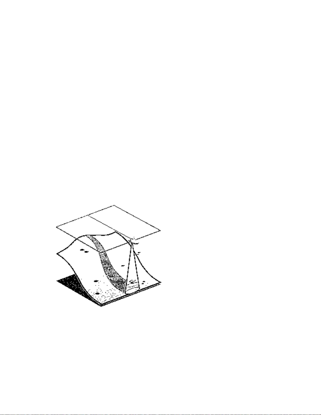
As a boat moves through the water, turbulence is generated by the weight of he boat, and the
thrust of the propeller(s). This turbulent water is normally confined in areas immediately aft of ribs,
strakes, and in the immediat e area of the propeller(s). It is very important to locate the transducer
in an area which is relatively free of turbulent water. If the prop(s) are forward of the transom, it
may be impossible to find an area clear from turbulence, and a different mounting technique
should be considered. On outboard or inboard/outboard boats it is best to stay at least 15” to the
side of the propeller(s).
If possible, viewing the transom of the boat while the boat is moving will provide the best means
of locating clean water. If maximum high-speed operation is a high priority, this is the
recommended method. If this is not possible, select a location on the transom where the hull
forward of this location is smooth, flat. And free of protrusions or ribs.
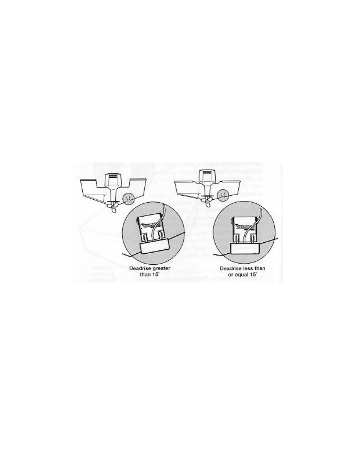
Another consideration is the angle of deadrise. The transducer, when mounted, should point
straight down. The design of the transducer will allow a deadrise of 15 degrees and remain
pointed straight down. If the deadrise is greater than about 15 degrees it will be necessary to
angle the transducer slightly. While this does not significantly degrade performance, you must
keep in mind that the readout may be somewhat to one side of the boat.
On boats with stepped hulls, it may be possible to mount the transducer on the transom behind a
step, as this area of the transom will not be in contact with the water at high speed.
Drilling the Mounting Holes
Once you have identified the location, remove the mounting template from the front of this
manual. This template provides a means of ensuring that the deadrise of the transom falls within
the allowable limits, and it locates the three mounting holes which must be drilled.
Hold the template on the transom of the boat in the location you have selected. Align the template
vertically, ensuring the lower edge of the transom on either side of the template falls within the
Page 6

horizontal lines on the template. If not, tilt the template slightly so that the lower edge of the
transom falls within the allowable range.
Using a pencil or punch, mark the three mounting holes onto the transom.
Using a 5/32” bit, drill the three holes to a depth of approximately 1”. On fiberglass hulls, it is best
to start with a smaller bit and use progressively larger drill bits to reduce the chance of chipping or
flaking the outer coating.
Mounting the Metal Bracket
Use a silicone sealant to fill the drilled holes, especially if the holes penetrated the transom wall.
Align the metal mounting bracket with the mounting holes. The bracket should be positioned so
that the center slot is above the outer two slots. (This bracket and all the other hardware supplied
is top quality stainless steel for maximum strength and corrosion protection). Thread the three
wood screws into the drilled holes, but do not completely tighten.
Page 7
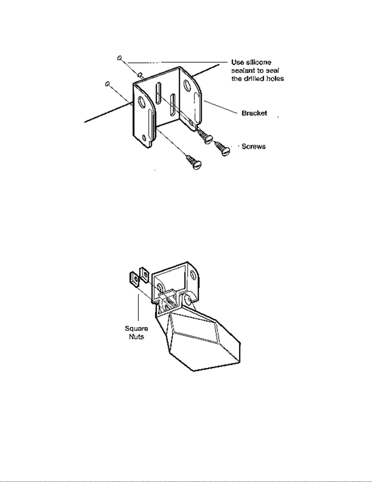
Assembling the Transducer Body
Attach the Pivot to the transducer body, as shown in the illustration below, using the two ¼’-20 x
5/8” machine screws, toothed washers, and square nuts. The toothed washers must fit on the
inside of the transducer ears. The square nuts are prevented from rotating by the pocket in back
of the pivot.
Loosely tighten the ¼”-20 screws with the Allen wrench (provided) so that the pivot angle can be
adjusted,
Page 8

Installing The Transducer Body To The Boat
Slide the assembled transducer into the metal bracket from the bottom, aligning the large hole at
the top of the bracket with the hole in the pivot.
Insert the pin the pivot holes in the bracket and pivot. The headed pin can be inserted from either
side of the bracket.
Place the nylon washer over the opposite end of the headed pin. Place the stainless washer over
the ¼”-20 x 3/8” screw threads and insert into the opposite end of the pin and finger tighten only.
Page 9

The screw has a thread-locking compound on the threads to prevent loosening, and should not
be fully tightened until all adjustments are made.
Adjusting The Running Position Of The Transducer
The running position of the transducer is now completely adjustable. Initially, adjust the
transducer as described in this manual. Further adjustments may be necessary to tweak the
installation after high speed testing. The metal bracket allows height and tilt adjustment, the pivot
screws allow angular adjustment.
Adjust the angle of the transducer body first, so it is parallel with the hull of the boat, and fully
tighten the two pivot screws using the supplied Allen wrench. Access to the pivot screws is
provided by the lower holes in the side of the mounting bracket.
Page 10

Note: On some hulls, it may be necessary to angle the transducer so that the back end is ¼”
lower than the front.
Next, adjust the height of the assembly so the face of the transducer is 1/8” to ¼” beneath the
bottom of the transom, and fully tighten the three mounting screws. In order to gain access to the
mounting screws, the transducer assembly must be pivo ted up in the bracket as shown. Be
careful not to alter the running angle as some force is necessary to pivot the assembly. If access
to the top mounting hole is not possible due to the selected height of the transducer, fully tighten
the two lower screws, then simply remove the headed pivot pin and the transducer assembly, and
tighten the top screw, then reassemble.
Finally, ensure that all mounting screws are fully tightened.
Routing the Cable
The transducer cable has a low profile connector that mus t be routed to the point where the HDR
600 unit will be mounted. Every boat is different and there may be several ways to route the
cable.
If you choose to pass the cable through the transom of the boat, a 1/3” hole must be drilled above
the water line. Fill this hole with silicone sealant, and use the supplied escutcheon plate to dress
the entry hole. This will require two #8 x 5/8” screws provided and drilled holes of 9/64.
Remember that the transducer can pivot 90 degrees in the bracket should an objec t be struck,
and sufficient cable slack should be allowed for this movement. It is best to route the cable to the
side of the transducer so the cable will not be damaged by the rotating transducer.
Cable clamps are provided to secure the cable to the transom using the same type of screws as
the escutcheon plate.
Page 11

Inside the boat there is often a channel or conduit used for other wiring, which can be used to
route the transducer cable forward. The transducer cable should not be cut or shortened, and
care should be used not to damage the cable insulation. Also, be sure to route the cable as far as
practical from the antenna cable of VHF radios or tachometer cables to reduce the possibility of
interference.
If the cable is too short for your application, extension cables are available at a reasonable cost
which can extend the transducer cable up to a total of 50 feet. Call Humminbird Customer
Support for more information.
INSTALLATION
INSTALLING THE HDR 600
Before installing the HDR 600, gather the parts you need: HDR 600, “U” Bracket, mounting
hardware, cable ties and transducer cable.
Next, consider where to mount the HDR 600. Try different positions on the console or deck of the
boat. Remember that the cables for the transducer and power must reach the mounting location.
Extension cables are available.
The mounting surface should be visible to the boat operator and adequately supported to protect
the HDR 600 from excess wave shock and vibration. Allow at least 2” clearance at the back,
sides, and top of the unit for connection, air flow, and ease of removal and installation.
Mark the desired location and drill a pilot hole.
Drill a 2 1/8” diameter hole using a hole saw and hand drill. This is a standard hole saw readily
available for rental or purchase. Or, any marine service shop can handle this task.
Page 12

Insert the HDR 600 from the front of the panel. Install the “U” bracket and wing nut from the rear
of the panel ensuring that the face of the HDR 600 is rotated upright.
If the panel into which you are mounting the unit is greater than ¼” thick, the “U” bracket may
appear too long. You may modify the “U” bracket by using pliers to break the legs of the “U”
bracket at the score lines.
Shorten the bracket gradually to avoid making it too short. Tighten the wing nut to secure the
installation.
Once the unit is secured to the dash, the buzzer can be secured either to the metal bracket or a
nearby wire bundle using the cable ties included.
Plug the transducer cable to the transducer connector. Notice the connector is keyed to prevent
reverse installation, so be careful not to force the plug into the connector. Next, proceed with
making the electrical connections.
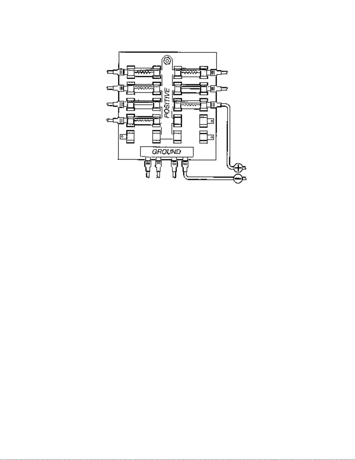
If your boat has an electrical system, there is probably fuse panel in the console area, which can
be used to attach the HDR 600 power cable. If a fuse terminal is available, use crimp-on type
electrical connectors (not included), which match the terminal on the fuse panel, and attach the
black wire to ground, and the red wire to 12 VDC power. Be sure to use a one-amp fuse in the
connection, 48” of power cable is included. You may shorten, or lengthen the cable using 18gauge multi-strand copper wire.
Page 13
CAUTION: Some boats have 24 or 36-volt electric systems. Be sure your HDR 600 is connected
to a 12 VDC power supply.
If you must wire the HDR 600 directly to a battery, be sure to install an in-line fuse holder and one
amp fuse (not included), for the protection of the unit. Humminbird is not responsible for overvoltage or over-current failures.
In order to minimize the potential for interference with other marine electronics, particularly VHF
radios, it is best to route the transducer cable and the antenna cable as far apart as possible. A
separate power source may be necessary to eliminate interference.
USING THE HDR 600
WHAT YOU SEE ON-SCREEN
The HDR 600 uses a backlit 7-segment display in conjunction with a 3-button keypad to control
all user functions. At initial power-up, the unit will begin normal operation and display the digital
depth and the units of measure. Figure 1 shows a typical view you might see on-screen at initial
power-up.
CONTROL FUNCTIONS
The HDR 600 uses 3 buttons to control the Shallow Alarm, Deep Alarm, Keel Offset, and Units of
Measure function. Wile in normal operation, pressing the SET button selects a Function and
blinks its corresponding indicator on the display. Once a Function has been selected it may be
adjusted by pressing the UP and Down arrow buttons to adjust the setting. Further presses of the
SET button will sequentially select the other functions for adjustment. All user settings are
remembered by the HDR 600, even when powered off.
Page 14

When in an active function, a single press to an arrow button will result in a single incremental
adjustment. Pressing and holding an arrow button will sequence through a range of adjustments.
If no adjustment is made for 5 seconds, the unit will return to normal operation.
Shallow Alarm
The SHALLOW ALARM function can be set for depths ranging from 1 to 20 feet and sounds an
alarm when the depth is less than the setting.
From normal operation pressing SET once will display the SHALLOW ALARM setting and blink
the “SHALLOW” icon. The UP ARROW will activate the SHALLOW ALARM AND ALSO increase
the selected value. The DOWN ARROW will reduce the value. Hold the UP ARROW until you
reach the desired depth setting.
Note: The maximum SHALLOW ALARM setting can not meet of exceed the current DEEP
ALARM setting.
After your selection is made, the unit will return to normal operation after 5 seconds. The
‘SHALLOW’ icon should now be visible (figure 4).
If the depth of the water is less then the selected value, the alarm will sound and the “SHALLOW”
icon will blink to indicate the alarm. Pressing any button will mute the alarm; pressing SET will
mute the alarm and activate the SHALLOW ALARM function for additional adjustment. To
permanently turn the alarm off, use the DOWN ARROW to return the display to ‘OFF’.
Deep Alarm
The DEEP ALARM can be set for depths up to 99 feet and sounds an alarm when the depth is
greater than the setting.
Press SET until the DEEP ALARM function becomes active. This is indicated by the blinking
‘DEEP ALARM” and also increases the selected value. The DOWN ARROW will reduce the
value. Continue to press and hold the UP ARROW until you reach your desired value.
Note: The minimum DEEP ALARM setting cannot meet or go below the current SHALLOW
ALARM setting.
After your selection is made, the unit will return to normal operation after 5 seconds. The ‘DEEP”
icon should now be visible (figure 6).
If the depth of the water is greater than the selected value , the alarm will sound and the icon will
blink to indicate the alarm. Pressing any button will mute the alarm; pressing SET will mute the
alarm and activate the DEEP ALARM function for additional adjustment. To permanently turn the
alarm off, use the DOWN ARROW to return the display to “OFF”.
Units
The UNITS Control Function selects the UNITS of measure for depth readout and alarm
functions, The three settings available are Feet, Meters or Fathoms.
Press SET until the UNITS function is activated on-screen. This is indicated by the blinking
UNITS icon. Pressing either arrow will allow you to select from the choices. Continue to press an
arrow until the desired readout is selected; FT for feet, M for meters, FA for fathoms.
Page 15

After your selection is made, the unit will return to normal operation after 5 seconds. The selected
units icon should now be visible as shown in figure 8.
Keel Offset
The Keel Offset function adjusts the digital depth readout to display depth readings from either
the waterline of the keel (lowest point) of the boat, instead of from the location of the transducer
which is usually somewhere in between. This permits optimum transducer location and depth
readouts suited to your needs.
To determine the value to enter into the Keel Offset setting, first decide whether depth from the
waterline or depth from the keel is desired. Measurements will need to be made for the location
desired.
For depth from the keel of the boat, accurately measure the vertical distance between the face of
the transducer and keel of the boat. This measurement will then be entered into the Keel Offset
function as a negative (-) number. (Figure 9).
For depth measurements from the waterline, accurately measure the vertical distance between
the face of the transducer and the waterline of the boat. This measurement will then be entered
into the Keel Offset function as a positive (+) number (Figure 10).
To enable Keel Offset press SET until the KO icon is displayed on the screen. The default setting
of the unit is off which is displayed as zero. From the default setting of 0.0, use the DOWN arrow
to enter the negative (-) number to set the unit for depth from the keel. Or from the default setting
of 0.0, use the UP arrow to enter a positive (+) number to set the unit for depth from the waterline.
The available settings are +10 to –10 feet. After your selection is made, the unit will return to
normal operation after 5 seconds. The “KO” icon should now be visible as shown in figure 13.
Figures 11, 12, and 13 depict a scenario where the KEEL OFFSET has been set to –2 feet.
Figure 13 shows the return to normal operation with the updated depth readout.
MAINTENANCE AND WARRANTY
TROUBLESHOOTING
Do not attempt to repair the HDR 600 yourself. There are no user serviceable parts inside, and
special tools and techniques are required for reassembly to ensure the waterproof integrity of the
housing. Repairs should be performed only by authorized Humminbird technicians.
Many requests for repair received by Humminbird involve units that do not actually need repair.
These units are returned “no problem found”. If you have a problem with your HDR 600, consult
the following troubleshooting guide before calling Customer Support or sending your unit in for
repair.
1. Nothing happens when I turn the unit on.
Check the power cable connection at both ends. Be sure that the cable is connected correctly to
a reliable power source- red lead to positive, black lead to negative ground. Ensure that the
power available at the mount is between 10 and 16 VDC. If the unit is wired through a fuse panel,
ensure that the panel is powered. Often accessory fuse panels are controlled by a separat e
switch or the ignition switch. Also, often a fuse can appear to be good when in fact it is not. Check
the fuse with a tester or replace it with a fuse known to be good.
Page 16

2. There is no bottom reading visible on the display.
There are a number of possible causes for this condition. If the loss of bottom information occurs
only at high speeds, then a transducer adjustment is needed. (refer to Transducer Installation).
Check the transducer cable connection on the back of the unit and ensure that the cable has not
been cut or pinched. Even a small abrasion in the cable can significantly affect performance.
3. When in very shallow water, he unit does not display a continuous depth.
This is normal in extremely shallow water, because the automatic range control can not lock onto
the bottom in depths of one foot or less.
4. The screen begins to fade out. Images are not as sharp as normal.
Check the input voltage. The HDR 600 will not operate on input voltages below 10 VDC.
5. The bottom reading disappears during a hard turn.
This is normal, as the transducer comes out of the water in a hard turn and will correct itself.
SPECIFICATIONS
Operating Frequency…………………………………200 kHz
Area of Coverage…………………………………….16 degrees at –10 db
Power Requirement………………………………….10 – 16 VDC
Display……………………………………………….Liquid Crystal
Unit Size……………………………………………..2.42” Dia. x 4.75”
Transducer (Standard)……………………………….XHS -6-16
Transducer Cable Length…………………………20 feet
Power Cable Length………………………………48”
Depth Capability………………………………….600 feet
Mounting…………………………………………In-Dash 2 1/8” hole
Unit Construction………………………………...High-Impact Plastic
 Loading...