

Page 1

Page 2

GUARANTEED DEPTH PERFORMANCE
Your Humminbird Digital is guaranteed to operate to 400 feet when the unit and transducer are
properly installed, following the instructions in this operations manual.
It cannot be emphasized enough how important it is to correctly install the unit and transducer.
Improper installation will void the depth guarantee because it can degrade the unit’s
performance.
Page 3

TRANSDUCER MOUNTING PROCEDURE
Humminbird’s high-speed transducer is supplied with your LCR. This transducer has been
designed to give good high speed readings on most all boat designs, including aluminum.
Please carefully consider the following before installing your transducer.
TRANSDUCER MOUNTING OPTIONS
A. Transom Mount - The Humminbird high speed transducer allows the transducer element to be
mounted below the bottom of the boat hull keeping the transducer out of turbulent water and
insuring good high speed operation. The transducer will abs orb the blow of any obstruction
Page 4
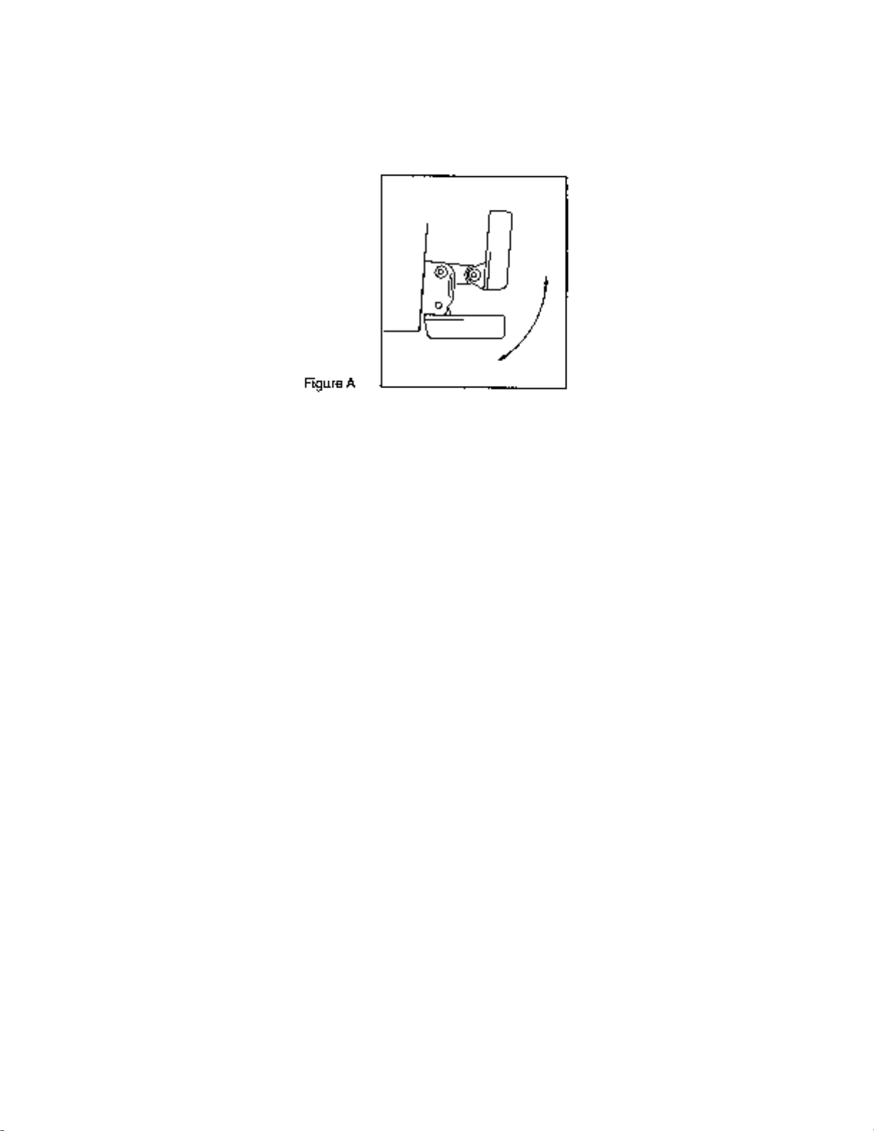
by rotating up out of the metal spring bracket without harming the transducer, or your boat.
The transducer can be re-engaged by simply rotating the transducer down and snapping it
back in place. (See Figure A)
B. Inside Hull Mount - The high speed transducer can be mounted inside the hull (without pivot
assembly) using the proper two-part epoxy, such as Humminbird’s epoxy kit. Even though
there is some loss of signal in shooting through the hull, your LCR will perform well with this
type of installation. You cannot shoot through the hull of an aluminum boat.
C. Trolling motor Mount - This type of transducer is not supplied with your LCR. It is designed to
mount on the foot of a trolling motor. You may exchange your un-used high speed
transducer for a trolling motor transducer. Call the Humminbird Customer Service
Department.
D. Bronz Thru-Hull Mount - This transducer is not supplied with your LCR but for an additional
cost you may exchange your un-used high speed transducer for a bronz thru-hull. The bronz
thru-hull transducer has a threaded stem which installs through a hole drilled in the boat hull,
leaving the housing exposed under the boat. This type of installation must be used for many
boats with in-board engines, because there is no suitable location on the transom away from
the noise and turbulence created by the prop. A bronz thru-hull transducer should be installed
by qualified personnel only.
The LCR will operate well at high speeds with a properly mounted transducer. Remember, a
transducer will not work transmitting through air or through air bubbles.
1. TRANSOM MOUNTING PROCEDURE
Step 1.
MOUNTING LOCATION- It is important that the transducer be mounted on the transom where
water flow is in constant contact with the trans ducer. You may wish to observe the rear of the
boat while it is moving through the water to determine the best mounting location.
Step 2.
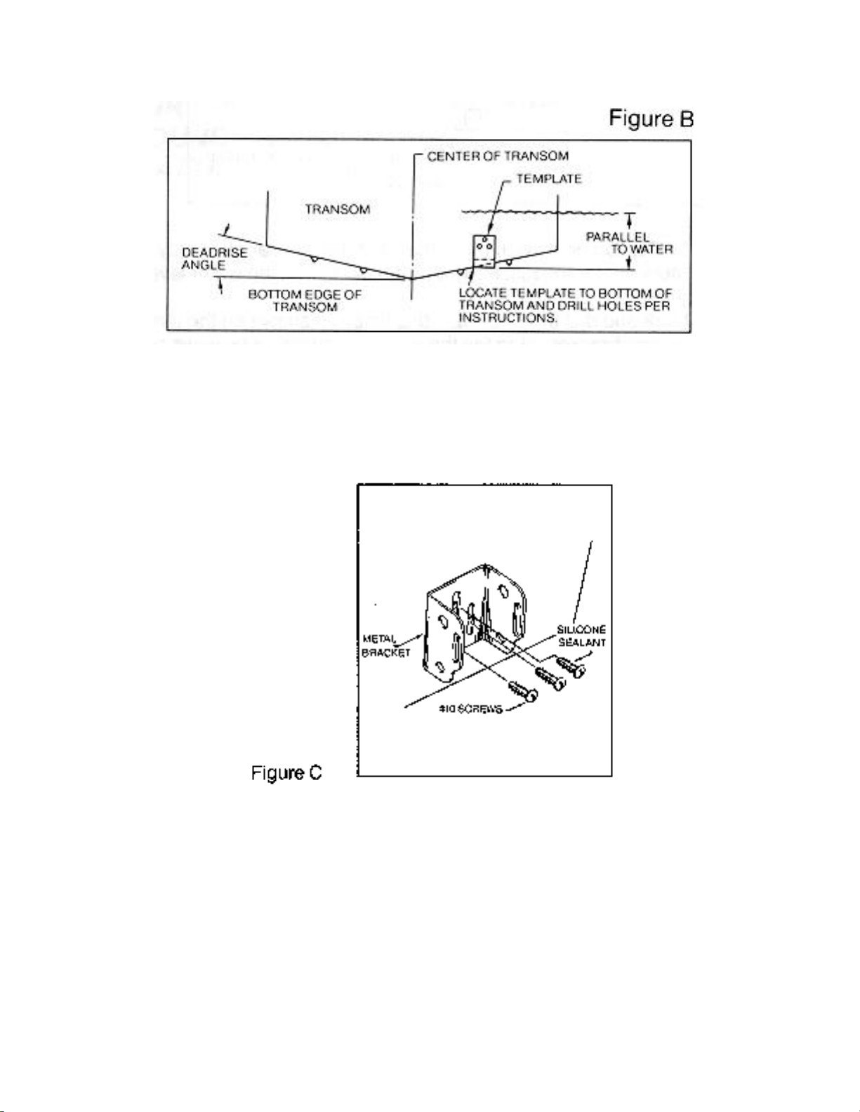
BRACKET INSTALLATION (Aluminum Boats)- To install the metal bracket on an aluminum boat
locate the template on the transom between rows of rivets, or ribs that are on the bottom of the
boat. Align the template so that the bottom corner of the template nearest the center of the
transom is on the bottom edge of the transom.
Page 5
Once the location is determined mark and drill three 7/64” dia.. holes noted on the template.
Attach the metal bracket using three #10 self threading screws supplied. Be sure to align holes in
the center of the
Bracket slots. On some aluminum boats it may be necessary to use a wood back-up plate. It is
important to use a silicone sealant between the screwhead and bracket in order to prevent
leaking. (See Figure C)
Step 2.
BRACKET INSTALLATION (Fiberglass Boats)- If your boat has a stepped transom located
below and under the main transom, the compact transducer design allows mounting in this area.
This mounting location is recommended for good reading at very high speeds. (See Figure D)
To install the metal bracket on a fiberglass boat, locate the template on the transom in the same
manner as for an aluminum boat. (See Figure C)
Page 6
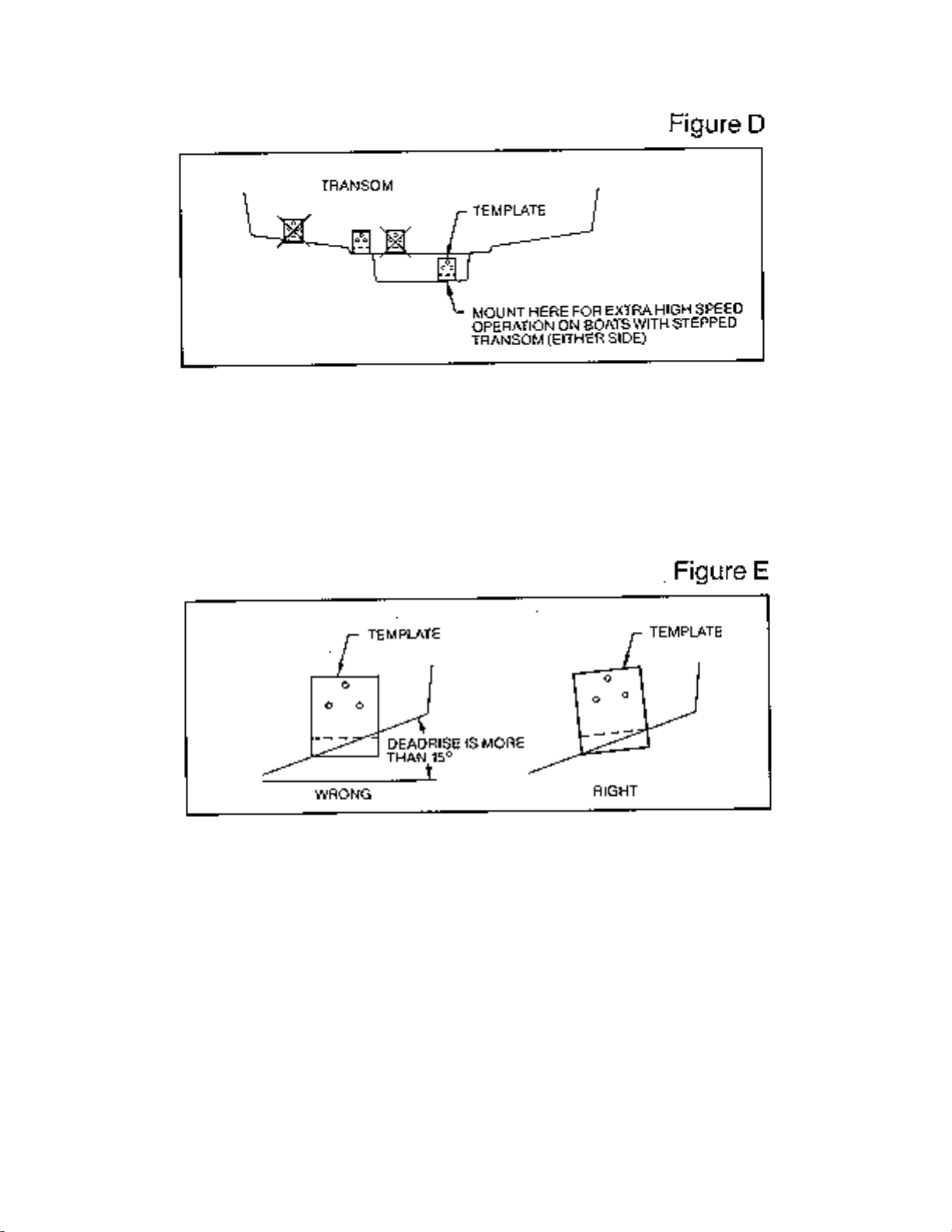
NOTE: On boats with more than 15 degree deadrise angle it may be necessary to mount the
transducer slightly off parallel with the water level. (See Figure E)
Mark and drill the three 9/64” dia. holes as shown on the template. Attach the metal bracket using
the three #10 self threading screws supplied. Be sure to align the holes so that they are centered
vertically in the three slots found in the bracket. It is important to use a silicone sealant between
the screwhead and bracket in order to prevent leaking.
Step 3.
TRANSDUCER PIVOT ASSEMBLY - Assemble the pivot to the transducer main body using the
two ¼”x5/8” allen head screws, two 3/8” tooth washers and two, ¼” square nuts. Make sure the
tooth washers are sandwiched between the transducer main body and the pivot. The square nuts
are trapped inside the pivot and will not rotate as the allen head screws are tightened.
HOWEVER, DO NOT TIGHTEN AT THIS POINT. (See Figure F)
Page 7

Step 4
TRANSDUCER ASSEMBLY - Insert the transducer assembly into the metal bracket from the
bottom. Push up until the holes in the plastic pivot align with the uppermost holes in the bracket.
Slide the O-ring on to the headed pin and insert it through the two parts. Assemble by screwing
the ¼”x3/8” allen head screw into the end of the pin and tighten. (See Figure G)
Step 5
ANGLE ALLIGHMENT- Set the transducer angle so that it is parallel with the bottom of the boat
hull. Once proper alignment is achieved, tighten the two allen head screws us ing the 5/32” allen
Page 8

wrench provided. The screws are visible through the access holes on each side of the metal
bracket. Check to make sure the transducer main body is rigidly fastened to the pivot. (See
Figure H)
Step 6
CHECK POSITION OF TRANSDUCER- At this point, check to see that the bottom of the
transducer is a minimum of ¼” below the bottom of the transom. (However, as noted in STEP 2,
the top of the transducer cannot fall below the bottom of the transom). If it is not, remove the
transducer assembly from the metal bracket by removing the pin installed during STEP 3. Loosen
the metal bracket mounting screws, re-position the bracket utilizing it’s slotted holes, tighten and
re-assemble. It may be necessary to replace the silicone sealant after this adjustment is made.
NOTE: It may be necessary to make several high speed runs to adjust transducer either
UP/DOWN or to re-adjust the angle to achieve optimum results.
Step 7
CABLE CLAMPS- Install cable clamps as necessary by drilling a 1/8” dia. hole for the # 8 screw
supplied.
2. INSIDE HULL MOUNTING PROCEDURE
Warning: In order to achieve proper results with this type installation, it is important that the
transducer be mounted by someone familiar with the use of two part epoxy adhesives. For this
reason, Techsonic Industries, Inc. will not be responsible for any damage due to the mounting of
your transducer in this manner.
NOTE: An Epoxy Kit (Part N. EPK) is available from Humminbird. This Epoxy Kit has been
formulated for Inside Hull Transducer Installation.
1. Select as flat an area as possible near the aft end and center of boat where the hull is thin
and not double. If the bottom has a runner down the center of boat, select an area to one side
of the runner, but as close to the runner as possible.
2. Clean the inside of the boat with lacquer thinner in the area transducer is to be mounted.
Outside of boat in this area should also be cleaned. (Not with lacquer thinner).
3. Put approximately one inch of water in the bottom of the boat.
4. Put transducer in the water. The bottom of the transducer should be in a flat area and should
be in good contact with the bottom of the boat.
5. Operate the LCR with the boat operating at high speed. The transducer may have to be
moved in order to find an area where satisfactory operation is observed.
6. When an area is found that produces satisfactory operation, mark the location of the
transducer.
Page 9

7. Remove the water and transducer and clean the marked area and the bottom of the
transducer thoroughly.
8. Using the Humminbird Epoxy Kit or equivalent, mix an ample amount of epoxy without
causing it to bubble and pour it in the area the transducer is to be mounted. The puddle
should be larger than the bottom of the transducer.
9. Coat the bottom of the transducer with epoxy, then put it in the center of the puddle and push
down on the transducer while moving it around in a circular motion. This forces out any air
bubbles that may be trapped between the bottom of the transducer and the hull of the boat.
10. Let epoxy cure then the transducer is ready to operate. No water is now required in the
bottom of the boat and gas and oil that is spilled inside of the boat will not degrade
performance as it will if the transducer is placed only in water.
CAUTION: Do not use the silicone seal or any soft adhesive to bond the transducer to the
hull. This will reduce the sensitivity of the unit.
CAUTIONS
1. Occasionally the “eye“ of your transducer may become dirty from storage or from contact with
oils present in boats or marina environments. (Oil will cause the “eye” to lose the intimate
contact with the water which is necessary for efficient operation.) The “eye” may be cleaned
with liquid detergent.
2. Improper installation of the transducer can alter the efficiency and accuracy of the entire
system.
3. If your boat of transducer is out of the water for a period of time, it may take a short period of
time for the transducer to become thoroughly “wetted” when returned to the water. Also, reentry may cause turbulence, which will create air bubbles in the “eye” of the transducer. The
bubbles will disappear in a short time or can be removed by rubbing the transducer “eye” with
your fingers while the transducer is in the water.
4. If your instrument should fail to function, be sure to check all the electrical connections before
removing the transducer or calling a serviceman.
5. Inspect your transducer cable and make sure that it has not been cut or damaged to the point
where it will affect the performance of the transducer. A slight nick or cut, exposing the outer
cable, can be repaired by wrapping with electrical tape. A transducer can be damaged if the
inner cable and outer cable are allowed to make contact. Such a problem can sometimes be
corrected by properly splicing the coaxial cable. This should only be attempted by a qualified
service technician.
6. If your LCR is not working properly and you suspect the problem might be in your transducer,
we would recommend you borrow a unit from a friend and try it on your boat. If the symptoms
are the same, you can almost be certain that the problem is in the transducer.
INSTALLING THE LCR
The LCR should be mounted on a flat, solid surface for maximum stability. The low profile swivel
mount has four holes drilled in the base. It is recommended that all four holes be used.
Position the swivel base and drill four ¼” diameter holes. Note: The LCR hole pattern Is the same
as for all Humminbird flasher units. Use hardware provided to mount this base to the boat.
Next place the gimbal bracket on the swivel base and attach with four small machine screws,
provided.
Place the LCR in the gimbal mount and make certain the rubber washers provided are placed
between the unit and the gimbal bracket Important: Note which side of the gimbal faces forward.
(Slots on gimbal bracket go towards rear). Also, rubber washer must be located between the unit
and the gimbal bracket.
Page 10

Install the mounting knobs and tighten snugly. The unit can now be swiveled and tilted to any
desired position.
Page 11

OTHER MOUNTING OPTIONS
1. The LCR gimbal bracket can also be mounted on the SM-4, quick disconnect swivel mount.
2. The LCR gimbal bracket can also be mounted directly to the dash without the swivel mount,
however, this method is not recommended since the unit cannot be rotated.
INSTALLING THE CABLES
Your LCR comes equipped with Humminbird’s new Angle-Lock power and transducer
connectors. The power connector is identified with the letter P on the back of the plug.
Page 12

It plugs into the outlet on the back of the unit marked “Power”. The transducer connector is
identified with the letter T and plugs into the outlet on the back of the unit marked “Transducer”.
Note: An adapter (AD-4) is available to allow use of an old waterproof (BNC) transducer with the
LCR, but be sure that the transducer is a 16degree. A 32-degree transducer cannot be used.
A 11/8” hole must be drilled to pull through the transducer connector. After drilling the hole, pull
the transducer connector up through the hole. If you are installing two units, both transducer
connectors can be pulled through this 1 1/8” inch hole. Next, push the power cable wires down
through the hole. A hole cover has been provided which will dress and hold the wires. Install the
hole cover after determining the necessary wire length from the hole.
The power cable has a red lead to the positive (+) post and the black lead to the negative (-) post.
Install a 1 amp fuse between the red cable and positive post of your 12-volt battery.
If a fuse panel is available, we recommend wiring the power cable into the fuse panel. Note: The
LCR must be fused separately from any other accessory.
Your Angle-Lock connectors can only be plugged in one way. Position the connector so the letter
P or T can be read and the 90 degree bend is pointed downward. Push the connector in as far as
it will go. Turn the positive locking ring as far as it will go clockwise until you feel it lock. Locking
ring as far as it will go clockwise until you feel it lock. Your connector is now locked into place.
Note: For easy access to the connectors, simply loosen the mounting knobs and tilt your LCR
forward. The connectors are now in full view and easy to plug or unplug.
Page 13

CAUTIONS
1. Occasionally the "eye" of your transducer may become dirty from storage or from contact
with oils present in boats or marina environments. (Oil will cause the "eye" to lose the intimate
contact with the water which is necessary for efficient operation.) The "eye" may be cleaned with
liquid detergent.
2. Improper installation of the transducer can alter the efficiency and accuracy of the entire
system.
3. If your boat or transducer is out of the water for a period of time, it may take a short
period of time for the transducer to become thoroughly "wetted" when returned to the water. Also,
re-entry may cause the turbulence which will create air bubbles on the "eye" of the transducer.
The bubbles will disappear in a short time or can be removed by rubbing the transducer "eye"
with your fingers while the transducer is in the water.
4. If your unit should fail to function, be sure to check all the electrical connections before
removing the transducer or calling a serviceman.
5. Inspect your transducer cable and make sure that it has not been cut or damaged to the
point where it will affect the performance of the transducer. A slight nick or cut, exposing the outer
cable, can be repaired by wrapping with electrical tape. A transducer can be damaged if the inner
cable and outer cable are allowed to make contact. Such a problem can sometimes be corrected
by properly splicing the coaxial cable. This should only be attempted by a qualified service
technician.
6. If your unit is not working properly and you suspect the problem might be in your
transducer, we would recommend you borrow a unit from a friend and try it on your boat. If the
symptoms are the same, you can almost be assured that the problem is in the transducer or in its
installation.
INSTALLING THE UNIT
Your Humminbird Digital has been designed for best viewing when mounted directly in front of or
to the right of the operator. This is particularly important for best viewing at night or in low light
conditions.
GIMBAL UNIT MOUNTING PROCEDURE
The unit may be mounted either on the deck or overhead, but it must be mounted on a flat, solid
surface for maximum stability. Select an area directly in front of or to the right of the operator for
best viewing, especially at night. If this is not possible, then angle the unit to ward the operator so
that you will be viewing it straight on. Before drilling holes make sure that you have room behind
the unit for the power and transducer connectors. With the slots on the gimbal bracket facing
away from you, use the gimbal bracket to locate the two screw locations. If you are mounting the
bracket to an aluminum or metal deck drill two 7/64" holes. If mounting to wood or fiberglass drill
two 9/64' holes. Mount the gimbal bracket using the two supplied self-tapping screws.
Place the unit on the gimbal bracket, making sure the rubber washers are placed
between the unit and the bracket (see Figure 11). Also, make certain that the correct side of the
gimbal bracket is facing forward.
Page 14

IN-DASH UNIT MOUNTING PROCEDURE
Select an area directly in front of or to the right of the operator for best viewing, especially
at night.
Before mounting the unit you must decide where to mount the alarm. It has been
designed to mount either to the back of the unit or away from the unit where it can be heard
easier. The alarm can be mounted on a surface near the dash or a hole can be drilled so that the
alarm can be sounded directly through the dash (see Figure 12).
NOTE: If you want to mount the alarm farther away than the one-foot cable will allow, you may
splice in a 2-conductor cable up to 20 feet from the unit.
The unit housing will mount in a 21/e° small gauge hole. Pass the cables through the
hole. Hold the unit housing in place and mark the location of the mounting screw holes. Drill four
3/32° pilot holes. Attach the housing with the four #6 x 1/2" screws provided (see Figure 13).
Page 15

You can now snap the display bezel over the housing, making sure that the control
buttons are properly positioned through the bezel. The bezel may be removed from the housing
by prying with a screwdriver ii the slots on either side (see Figure 14).
Page 16

INSTALLING THE CABLES
Your unit has two connectors, a transducer connector and a power connector. The
transducer connector attaches to the transducer cable.
The power connector attaches to the power cable. The power cable has a red lead and a
black lead. Connect this cable to a 12-volt DC Power Source (battery). Attach the red to the
positive (+) post and the black lead to the negative (-) post. Install a 1 amp fuse between the red
cable and positive post of your 12-volt battery. If a fuse panel is available, we recommend wiring
the power cable into the fuse panel. 'Note: The Humminbird Digital must be fused separately from
any other accessory.
If you are installing the gimbal mounted unit, a 9/,6" hole should be drilled in the dash to
pull the transducer connector up and to feed the power leads down. A hole cover has been
provided which will dress and hold the wires. Install the hole cover after determining the
necessary length from the hole.
TESTING YOUR UNIT AND TRANSDUCER INSTALLATION
After installing the unit, transducer, and cables, you are ready to test the installation. You
should put your boat in the water to test the unit because the transducer cannot transmit and
receive properly through air.
INITIAL UNIT TESTING
With your boat in the water at idle or at a very slow speed. Turn your unit on by pushing
the "on" button. The unit's computer will automatically locate the bottom and show the depth on
the display.
TROUBLE SHOOTING: If nothing happens when the "on" button is pushed, check your
electrical connections and fuse. Also check that the red wire on the power cable is connected to
the positive battery terminal and that the black wire is connected to the negative battery terminal.
If these wires are reversed it will not damage the unit. It is normal if when reversing the boat, the
bottom return is lost, since air from the prop is being forced under the transducer. Remember the
transducer cannot transmit through air.
TROUBLE SHOOTING: If the display comes on when the "on" button is pushed but the
bottom depth is not displayed, check that the transducer connector is securely locked to the rear
of the unit. Also insure that the transducer is completely submerged. A transducer cannot work
properly in air or through air bubbles in the water.
TROUBLE SHOOTING: In 1 or 2 feet of water the bottom depth may blank or go off. This
is normal in very shallow water. This is also normal in deeper water under high clutter conditions.
TROUBLE SHOOTING: If the display is not showing a steady bottom reading (if it is
blanking or going on and off), begin to systematically turn
off other equipment on the boat. In this way you can isolate which piece of equipment is
generating the interference. After isolating the problem, check that the equipment is properly
grounded. Try re-routing the power and transducer cables away from the source of the
interference. You may have to physically separate the two pieces of equipment.
TROUBLE SHOOTING: If the unit comes on without pressing the "on" button or if you
cannot turn it off by pressing the "on" button, carefully inspect the transducer cable. This condition
will be seen if the outer jacket of the cable has been cut and is touching any metal piece of the
boat.
TRANSDUCER INSTALLATION TEST
After verifying that your unit is working properly, you are ready to increase boat speed to
test the transducer installation. As you increase boat speed the unit should give a continuous
bottom return. With a proper transducer installation your Humminbird Digital will perform at
speeds up to 75 miles per hour.
TROUBLE SHOOTING: If at high speeds the bottom return is not continuous or it blanks
out, then the transducer installation or location is such that air is going under the transducer face.
Page 17

Refer back to the transducer mounting procedure for adjustments or for other mounting options.
NOTE: It is not unusual for the bottom reading to occasionally blank out. This is caused when the
unit temporarily looses the bottom. Rather than display an incorrect bottom depth, the
Humminbird Digital will blank out the display until the correct bottom is found again.
TROUBLE SHOOTING: If the bottom reading is lost while making a hard turn, the
transducer is coming out of the water during the turn.
OPERATIONAL INSTRUCTIONS
With only four buttons your Humminbird Digital is very easy to use. The use of each
button is explained below, as well as some special functions such as selecting feet, meters, or
fathoms and the option of deleting the decimal point.
Power On-Off
Power to your Humminbird Digital is controlled by the button marked "on". Pressing this
button once turns the unit on. Pressing it again turns the unit off.
Night Light
The night light automatically turns on when the unit power is turned on. Red light emitting
diodes, (LED's), are used to backlight the display.
These LED's require very little power and should never need replacement. You will see the red
backlight as the surrounding light conditions become low or dark.
Feet, Meters, Fathoms
The unit of measure may be selected by using the "on" button. With the unit turned off,
press in and hold down the "on" button. Watching the display, in about one second you will notice
the unit of measure changing from feet to meters to fathoms to feet, etc. When the desired unit of
measure is displayed release the "on" button. This unit is now set and will not change even when
power is turned off or is disconnected.
Alarm On-Off
The bottom alarm is turned on and off by pressing the alarm button. The alarm symbol
appearing in the upper right portion of the display indicates that the bottom alarm is on.
The alarm will sound when the bottom reading becomes equal to or less than the alarm
setting.
Alarm Setting
The _A (increase) and (decrease) buttons are used to display or change the alarm
settings. Pressing either button once will cause the alarm setting to be displayed. Continuing to
press either button will change the alarm setting. Holding the button down will cause the setting to
change rapidly. The alarm setting will always flash on the display so you can always separate it
from the bottom depth reading.
The alarm is set in whole increments (no decimal settings). Once a setting is entered, it
will not change after the power has been turned off or if the power is disconnected.
DELETING THE DECIMAL POINT
If you would rather not have a decimal point in bottom depth reading, it can be deleted.
To delete the dec imal point, press both the _A and buttons at the same time. Use the same
procedure to add the decimal point. The decimal point setting will not change after the power has
been turned off or is disconnected.
 Loading...