

Humminbird GPS Receiver Accessories Manual
531478-4_B
GPS Receiver and
GPS Receiver/Heading Sensor
GPS Receiver and
GPS Receiver/Heading Sensor

Thank You!
Thank you for choosing Humminbird®, the #1 name in Fishfinders. Humminbird®
has built its reputation by designing and manufacturing top-quality, thoroughly
reliable marine equipment. Your Humminbird® accessory is designed for troublefree use in even the harshest marine environment. In the unlikely event that
your Humminbird® accessory does require repairs, we offer an exclusive Service
Policy - free of charge during the first year after purchase, and available at a
reasonable rate after the one-year period. For complete details, see the separate
warranty card included with your accessory. We encourage you to read this
operations manual carefully in order to get full benefit from all the features and
applications of your Humminbird® product.
Contact our Customer Resource Center at 1-800-633-1468 or visit our Web
site at humminbird.com.
WARNING! This device should not be used as a navigational aid to prevent collision,
grounding, boat damage, or personal injury. When the boat is moving, water depth
may change too quickly to allow time for you to react. Always operate the boat at very
slow speeds if you suspect shallow water or submerged objects.
WARNING! The electronic chart in your Humminbird® unit is an aid to navigation
designed to facilitate the use of authorized government charts, not to replace them.
Only official government charts and notices to mariners contain all of the current
information needed for the safety of navigation, and the captain is responsible for their
prudent use.
WARNING! Compass Safe Distance: Do NOT install the Heading Sensor near ferrous
metals or near anything that may create a magnetic field or interference. The Heading
Sensor must be installed at least 3 feet (1m) from other magnetic or ferrous materials
on the boat.
WARNING! Humminbird® is not responsible for the loss of data files (waypoints,
routes, tracks, groups, recordings, etc.) that may occur due to direct or indirect damage
to the unit’s hardware or software. It is important to back up your control head’s data
files periodically. Data files should also be saved to your PC before restoring the unit’s
defaults or updating the software. See your Humminbird® online account at
humminbird.com and the Waypoint Management Guide on your Humminbird®
Manual CD for details.

WARNING! Disassembly and repair of this electronic unit should only be performed by
authorized service personnel. Any modification of the serial number or attempt to repair
the original equipment or accessories by unauthorized individuals will void the warranty.
WARNING! This product contains chemicals known to the State of California to cause
cancer and/or reproductive harm.
ENVIRONMENTAL COMPLIANCE STATEMENT: It is the intention of Johnson
Outdoors Marine Electronics, Inc. to be a responsible corporate citizen, operating in
compliance with known and applicable environmental regulations, and a good
neighbor in the communities where we make or sell our products.
WEEE DIRECTIVE: EU Directive 2002/96/EC “Waste of Electrical and Electronic
Equipment Directive (WEEE)” impacts most distributors, sellers, and manufacturers of
consumer electronics in the European Union. The WEEE Directive requires the producer
of consumer electronics to take responsibility for the management of waste from their
products to achieve environmentally responsible disposal during the product life cycle.
WEEE compliance may not be required in your location for electrical & electronic
equipment (EEE), nor may it be required for EEE designed and intended as fixed or
temporary installation in transportation vehicles such as automobiles, aircraft, and
boats. In some European Union member states, these vehicles are considered outside
of the scope of the Directive, and EEE for those applications can be considered
excluded from the WEEE Directive requirement.
This symbol (WEEE wheelie bin) on product indicates the product must not be
disposed of with other household refuse. It must be disposed of and collected
for recycling and recovery of waste EEE. Johnson Outdoors Marine Electronics,
Inc. will mark all EEE products in accordance with the WEEE Directive. It is our
goal to comply in the collection, treatment, recovery, and environmentally sound disposal
of those products; however, these requirements do vary within European Union member
states. For more information about where you should dispose of your waste equipment
for recycling and recovery and/or your European Union member state requirements,
please contact your dealer or distributor from which your product was purchased.
ROHS STATEMENT: Product designed and intended as a fixed installation or part of
a system in a vessel may be considered beyond the scope of Directive 2002/95/EC of
the European Parliament and of the Council of 27 January 2003 on the restriction of
the use of certain hazardous substances in electrical and electronic equipment.

NOTE: Some features discussed in this manual require a separate purchase, and some
features are only available on international models. Every effort has been made to
clearly identify those features. Please read the manual carefully in order to understand
the full capabilities of your model.
NOTE: The illustrations in this manual may not look the same as your product, but your
unit will function in the same way.
NOTE: To purchase accessories for your control head, visit our Web site at
humminbird.com or contact our Customer Resource Center at 1-800-633-1468.
NOTE: The procedures and features described in this manual are subject to change
without notice. This manual was written in English and may have been translated to
another language. Humminbird® is not responsible for incorrect translations or
discrepancies between documents.
700 Series™, 800 Series™, 900 Series™, 1100 Series™, Humminbird®, HumminbirdPC™,
X-Press™ Menu, SmartCast®, and WeatherSense® are trademarked by or registered
trademarks of Johnson Outdoors Marine Electronics, Inc.
© 2012 Johnson Outdoors Marine Electronics, Inc. All rights reserved.
ATTENTION INTERNATIONAL CUSTOMERS: Products sold in the U.S. are not
intended for use in the international market. Humminbird® international units provide
international features and are designed to meet country and regional regulations.
Languages, maps, time zones, units of measurement, and warranty are examples of
features that are customized for Humminbird® international units purchased through
our authorized international distributors.
To obtain a list of authorized international distributors, please visit our Web site at
humminbird.com or contact our Customer Resource Center at (334) 687-6613.

Overview 1
How GPS and Trackplotting Work . . . . . . . . . . . . . . . . . . . . . . . . . . . . . . . . . . . . 2
How the Heading Sensor Works . . . . . . . . . . . . . . . . . . . . . . . . . . . . . . . . . . . . . 3
Installation Overview 4
Choose the Mounting Location . . . . . . . . . . . . . . . . . . . . . . . . . . . . . . . . . . . . . . 4
Install the Sensor . . . . . . . . . . . . . . . . . . . . . . . . . . . . . . . . . . . . . . . . . . . . . . . . . 5
Stem Mount with 1” - 14 Thread . . . . . . . . . . . . . . . . . . . . . . . . . . . . . . . . . . 6
Access Under Mounting Location . . . . . . . . . . . . . . . . . . . . . . . . . . . . . . . . . . 8
No Access Under Mounting Location . . . . . . . . . . . . . . . . . . . . . . . . . . . . . . 10
Connect to the Control Head . . . . . . . . . . . . . . . . . . . . . . . . . . . . . . . . . . . . . . . 12
Power on and Confirm GPS Reception . . . . . . . . . . . . . . . . . . . . . . . . . . . . . . . 14
Confirm the Baud Rate (for devices connected to the pigtail only) . . . . . . . . . . . . . 15
Confirm the Heading Sensor Operation (Heading Sensors only [AS GPS HS]) . . . 16
Views 18
Bird's Eye View . . . . . . . . . . . . . . . . . . . . . . . . . . . . . . . . . . . . . . . . . . . . . . . . . . 19
Track View. . . . . . . . . . . . . . . . . . . . . . . . . . . . . . . . . . . . . . . . . . . . . . . . . . . . . . 20
Combo View . . . . . . . . . . . . . . . . . . . . . . . . . . . . . . . . . . . . . . . . . . . . . . . . . . . . 21
View Orientation. . . . . . . . . . . . . . . . . . . . . . . . . . . . . . . . . . . . . . . . . . . . . . . . . 22
Introduction to Navigation 23
Waypoints, Routes, and Tracks . . . . . . . . . . . . . . . . . . . . . . . . . . . . . . . . . . . . . 23
Save, Edit, or Delete a Waypoint. . . . . . . . . . . . . . . . . . . . . . . . . . . . . . . . . . . . 25
Navigate to a Waypoint or Position. . . . . . . . . . . . . . . . . . . . . . . . . . . . . . . . . . 27
Add a Waypoint Target or Trolling Grid . . . . . . . . . . . . . . . . . . . . . . . . . . . . . . . 28
Save or Clear a Current Track . . . . . . . . . . . . . . . . . . . . . . . . . . . . . . . . . . . . . . 29
Edit, Delete, or Hide Saved Tracks. . . . . . . . . . . . . . . . . . . . . . . . . . . . . . . . . . . 29
The Menu System 31
Start-Up Options Menu 32
Normal . . . . . . . . . . . . . . . . . . . . . . . . . . . . . . . . . . . . . . . . . . . . . . . . . . . . . . . . 32
Simulator . . . . . . . . . . . . . . . . . . . . . . . . . . . . . . . . . . . . . . . . . . . . . . . . . . . . . 33
System Status . . . . . . . . . . . . . . . . . . . . . . . . . . . . . . . . . . . . . . . . . . . . . . . . . . 33
Self Test . . . . . . . . . . . . . . . . . . . . . . . . . . . . . . . . . . . . . . . . . . . . . . . . . . . . . . . 34
Accessory Test . . . . . . . . . . . . . . . . . . . . . . . . . . . . . . . . . . . . . . . . . . . . . . . . . . 34
GPS Diagnostic View . . . . . . . . . . . . . . . . . . . . . . . . . . . . . . . . . . . . . . . . . . . . . 35
PC Connect
(with PC Connect Cable only) . . . . . . . . . . . . . . . . . . . . . . . . . . . . . . . . 36
X-Press™ Menu 37
i
Table of Contents

Main Menu 38
User Mode (Normal or Advanced). . . . . . . . . . . . . . . . . . . . . . . . . . . . . . . . . . . 39
Sonar X-Press™ Menu (Sonar Views only) 41
Mark . . . . . . . . . . . . . . . . . . . . . . . . . . . . . . . . . . . . . . . . . . . . . . . . . . . . . . . . . . 42
Cancel Navigation
(only when navigating) . . . . . . . . . . . . . . . . . . . . . . . . . . . . . . . 42
Navigation X-Press™ Menu (Navigation Views only) 43
Mark . . . . . . . . . . . . . . . . . . . . . . . . . . . . . . . . . . . . . . . . . . . . . . . . . . . . . . . . . . 44
Zoom . . . . . . . . . . . . . . . . . . . . . . . . . . . . . . . . . . . . . . . . . . . . . . . . . . . . . . . . . . 44
Go To . . . . . . . . . . . . . . . . . . . . . . . . . . . . . . . . . . . . . . . . . . . . . . . . . . . . . . . . . . 44
Waypoint [Name]
(only with an active cursor on a waypoint) . . . . . . . . . . . . . . . . . . 44
Cursor to Waypoint
(Track or Combo View only) . . . . . . . . . . . . . . . . . . . . . . . . . . . 45
Save Current Track . . . . . . . . . . . . . . . . . . . . . . . . . . . . . . . . . . . . . . . . . . . . . . 45
Clear Current Track. . . . . . . . . . . . . . . . . . . . . . . . . . . . . . . . . . . . . . . . . . . . . . . 45
Skip Next Waypoint
(only when navigating). . . . . . . . . . . . . . . . . . . . . . . . . . . . . . 45
Cancel Navigation
(only when navigating) . . . . . . . . . . . . . . . . . . . . . . . . . . . . . . . 46
Remove Target
(only if a target is active) . . . . . . . . . . . . . . . . . . . . . . . . . . . . . . . . 46
Remove Grid
(only if a grid is active) . . . . . . . . . . . . . . . . . . . . . . . . . . . . . . . . . . . . 46
Sonar Window
(Combo View only). . . . . . . . . . . . . . . . . . . . . . . . . . . . . . . . . . . . . 46
Waypoint [Name]
(most recently-created waypoint). . . . . . . . . . . . . . . . . . . . . . . . . 47
Alarms Menu Tab 48
Off Course Alarm . . . . . . . . . . . . . . . . . . . . . . . . . . . . . . . . . . . . . . . . . . . . . . . . 49
Arrival Alarm. . . . . . . . . . . . . . . . . . . . . . . . . . . . . . . . . . . . . . . . . . . . . . . . . . . . 49
Drift Alarm . . . . . . . . . . . . . . . . . . . . . . . . . . . . . . . . . . . . . . . . . . . . . . . . . . . . . 50
Navigation Menu Tab 51
Current Track. . . . . . . . . . . . . . . . . . . . . . . . . . . . . . . . . . . . . . . . . . . . . . . . . . . . 52
Saved Tracks . . . . . . . . . . . . . . . . . . . . . . . . . . . . . . . . . . . . . . . . . . . . . . . . . . . . 53
Waypoints. . . . . . . . . . . . . . . . . . . . . . . . . . . . . . . . . . . . . . . . . . . . . . . . . . . . . . 53
View Orientation. . . . . . . . . . . . . . . . . . . . . . . . . . . . . . . . . . . . . . . . . . . . . . . . . 54
Casting Rings
(Advanced). . . . . . . . . . . . . . . . . . . . . . . . . . . . . . . . . . . . . . . . . . . 54
North Reference . . . . . . . . . . . . . . . . . . . . . . . . . . . . . . . . . . . . . . . . . . . . . . . . . 54
Waypoint Proximity Flags
(Advanced) . . . . . . . . . . . . . . . . . . . . . . . . . . . . . . . . . 55
Waypoint Decluttering
(Advanced). . . . . . . . . . . . . . . . . . . . . . . . . . . . . . . . . . . . 55
Grid Rotation. . . . . . . . . . . . . . . . . . . . . . . . . . . . . . . . . . . . . . . . . . . . . . . . . . . . 56
Trackpoint Interval . . . . . . . . . . . . . . . . . . . . . . . . . . . . . . . . . . . . . . . . . . . . . . . 56
Track Min Distance
(Advanced) . . . . . . . . . . . . . . . . . . . . . . . . . . . . . . . . . . . . . . 56
ii
Table of Contents

Track Color Range. . . . . . . . . . . . . . . . . . . . . . . . . . . . . . . . . . . . . . . . . . . . . . . . 57
Map Datum
(Advanced) . . . . . . . . . . . . . . . . . . . . . . . . . . . . . . . . . . . . . . . . . . . . 57
North-Up Indicator . . . . . . . . . . . . . . . . . . . . . . . . . . . . . . . . . . . . . . . . . . . . . . . 57
Course Projection Line . . . . . . . . . . . . . . . . . . . . . . . . . . . . . . . . . . . . . . . . . . . . 57
Heading Offset
(Advanced, Heading Sensors only) . . . . . . . . . . . . . . . . . . . . . . . . . . 58
Heading Line
(Advanced, Heading Sensors only). . . . . . . . . . . . . . . . . . . . . . . . . . . . 58
Delete All Nav Data
(Advanced). . . . . . . . . . . . . . . . . . . . . . . . . . . . . . . . . . . . . . 58
Continuous Navigation Mode . . . . . . . . . . . . . . . . . . . . . . . . . . . . . . . . . . . . . . 58
GPS Receiver Override
(Advanced). . . . . . . . . . . . . . . . . . . . . . . . . . . . . . . . . . . . 59
Setup Menu Tab 60
Units - Distance . . . . . . . . . . . . . . . . . . . . . . . . . . . . . . . . . . . . . . . . . . . . . . . . . 61
Units - Speed . . . . . . . . . . . . . . . . . . . . . . . . . . . . . . . . . . . . . . . . . . . . . . . . . . . 61
Triplog Reset . . . . . . . . . . . . . . . . . . . . . . . . . . . . . . . . . . . . . . . . . . . . . . . . . . . 61
Select Readouts
(Advanced, Sonar View only). . . . . . . . . . . . . . . . . . . . . . . . . . . . . 62
Local Time Zone
(Advanced). . . . . . . . . . . . . . . . . . . . . . . . . . . . . . . . . . . . . . . . . 63
Daylight Saving Time
(Advanced). . . . . . . . . . . . . . . . . . . . . . . . . . . . . . . . . . . . . 64
Position Format
(Advanced) . . . . . . . . . . . . . . . . . . . . . . . . . . . . . . . . . . . . . . . . . 64
Time Format
(Advanced, International only). . . . . . . . . . . . . . . . . . . . . . . . . . . . . . . 64
Date Format
(Advanced, International only) . . . . . . . . . . . . . . . . . . . . . . . . . . . . . . . 64
NMEA Output
(Advanced) . . . . . . . . . . . . . . . . . . . . . . . . . . . . . . . . . . . . . . . . . . 65
Troubleshooting 66
Fishing System Doesn’t Power Up. . . . . . . . . . . . . . . . . . . . . . . . . . . . . . . . . . . 66
Fishing System Defaults to Simulator with a Transducer Attached. . . . . . . . . 66
Display Problems . . . . . . . . . . . . . . . . . . . . . . . . . . . . . . . . . . . . . . . . . . . . . . . . 67
Finding the Cause of Noise . . . . . . . . . . . . . . . . . . . . . . . . . . . . . . . . . . . . . . . . 68
GPS & Navigation Glossary 69
Contact Humminbird® 73
NOTE: Entries in this Table of Contents which list (International only) are only available
on products sold outside of the U.S. by our authorized international distributors. To
obtain a list of authorized international distributors, please visit our Web site at
humminbird.com or contact our Customer Resource Center at (334) 687-6613.
iii
Table of Contents

Overview
The Humminbird® Sensor Accessory Kit includes the following items depending
on the Sensor model you purchased:
The following functionality will be supported by your trackplotter when it is
connected to the Sensor:
• View current position
• View current track (breadcrumb trail)
• View precision speed and heading from your GPS receiver
• Save tracks and waypoints
• Travel a route and navigate from one waypoint to the next
• View the heading from the Heading Sensor (AS GPS HS only)
NOTE: If your control head is a chartplotter, there will be additional functionality when
the Sensor is connected to the control head. See your control head operations manual
and the Humminbird® Waypoint Management Guide for more information. The
manuals are included on the CD that was included with your control head, or you can
download these manuals from our Web site at humminbird.com.
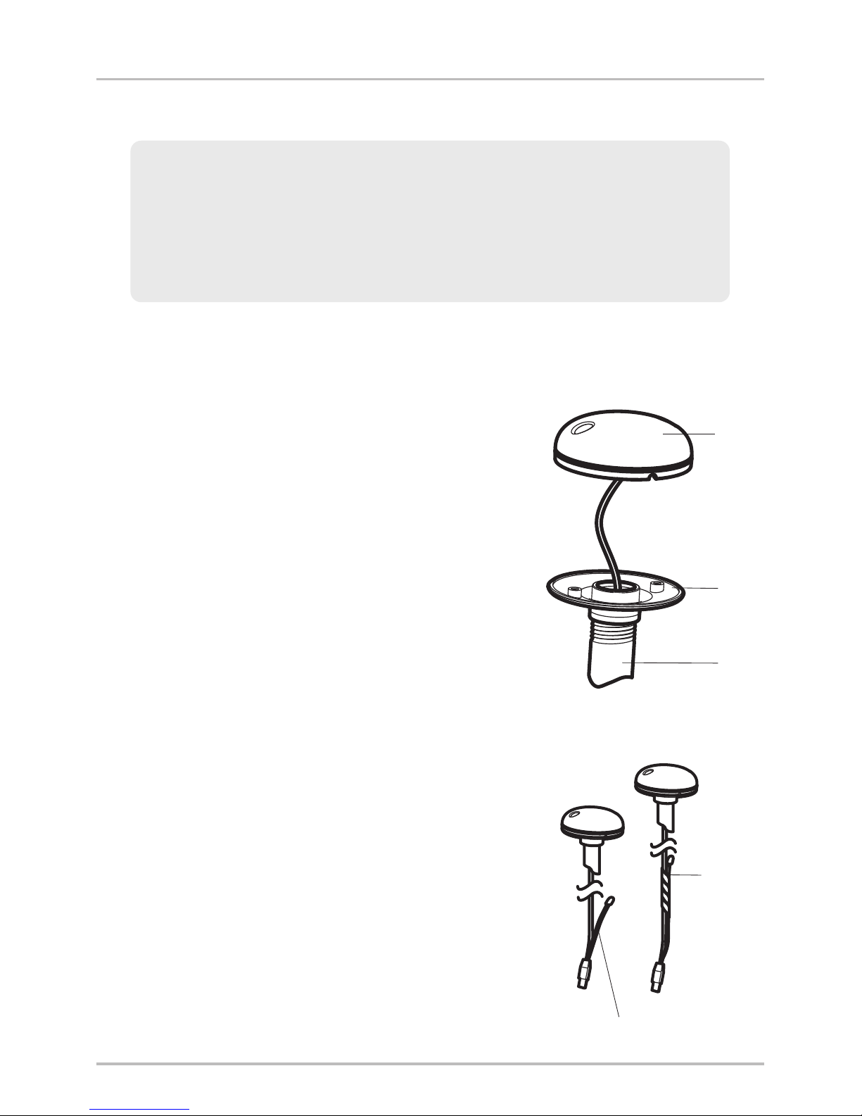
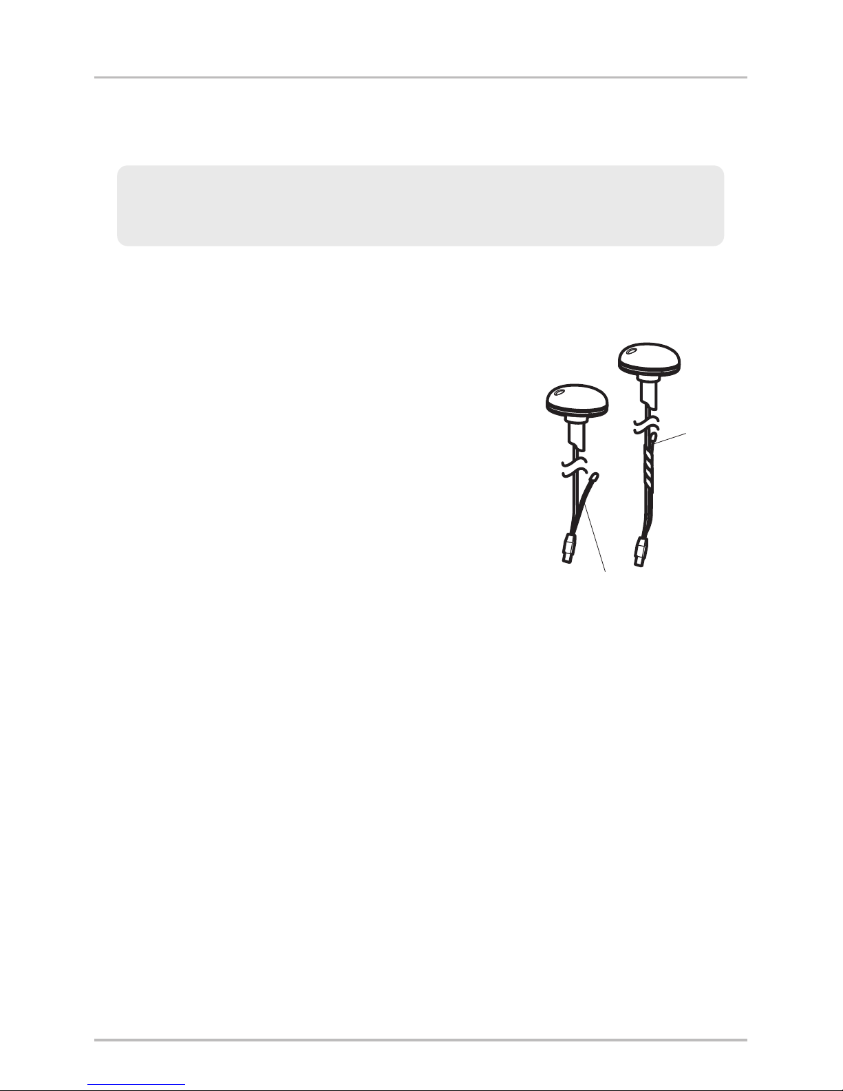
GPS Receiver
(AS GR16, AS GR50, AS GRP)
Sensor with internal GPS Receiver.
Cable length is 20 ft (6m).
Y-Cable (AS YC) for multiple accessory
attachment
Hardware kit for stem or deck mounting
Accessory Manual
GPS Receiver/Heading Sensor
(AS GPS HS)
Sensor with internal GPS Receiver and
Compass. Cable length is 20 ft (6m).
Y-Cable (AS YC) for multiple accessory
attachment
Hardware kit for stem or deck mounting
Accessory Manual
NOTE: The stem mount is not included. To purchase extension cables and other
accessories, see our Web site at humminbird.com or call our Customer Resource
Center at 1-800-633-1468.
1
Overview
2
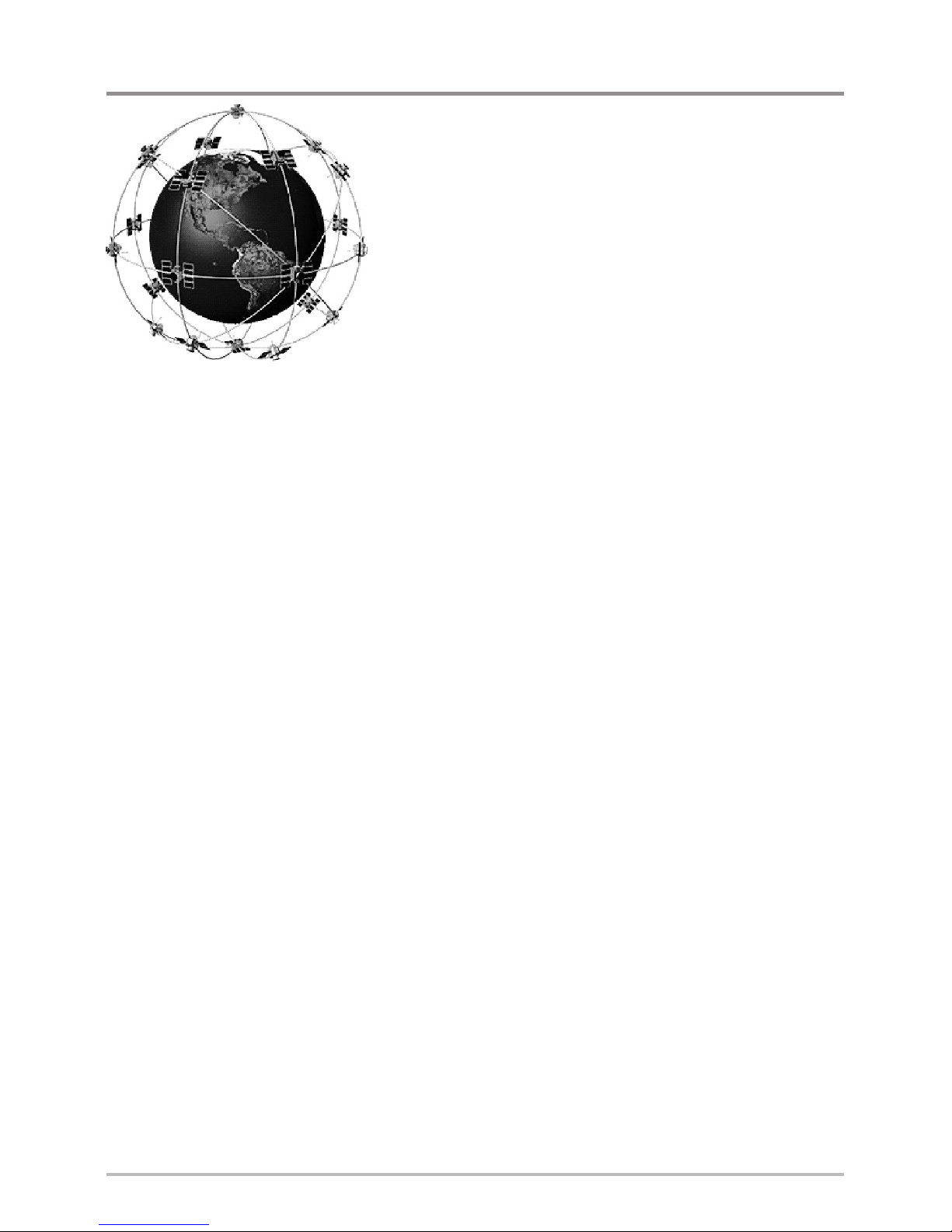
How GPS and Trackplotting Work
Your Humminbird® uses GPS to determine your
position and display it on a grid.
GPS uses a constellation of satellites that
continually send radio signals to the earth. The
GPS receiver on your boat receives signals from
satellites that are visible to it. Based on time
differences between each received signal, the
GPS receiver determines its distance to each
satellite. With distances known, the GPS receiver
mathematically triangulates its own position.
With 5 updates per second, the GPS receiver then
calculates its velocity and bearing.
GPS was originally intended for military use; however, civilians may also take
advantage of its highly accurate position capabilities, typically within +/– 2.5
to 10 meters, depending on your conditions and your Humminbird® model. This
means that 95% of the time, the GPS receiver will read a location within
+/– 2.5 to 10 meters of your actual position.
Your GPS receiver also uses information from WAAS (the Wide Area
Augmentation System), EGNOS (the European Geostationary Navigation
Overlay Service), and MSAS (the MTSAT Satellite Augmentation System)
satellites if they are available in your area.
Overview
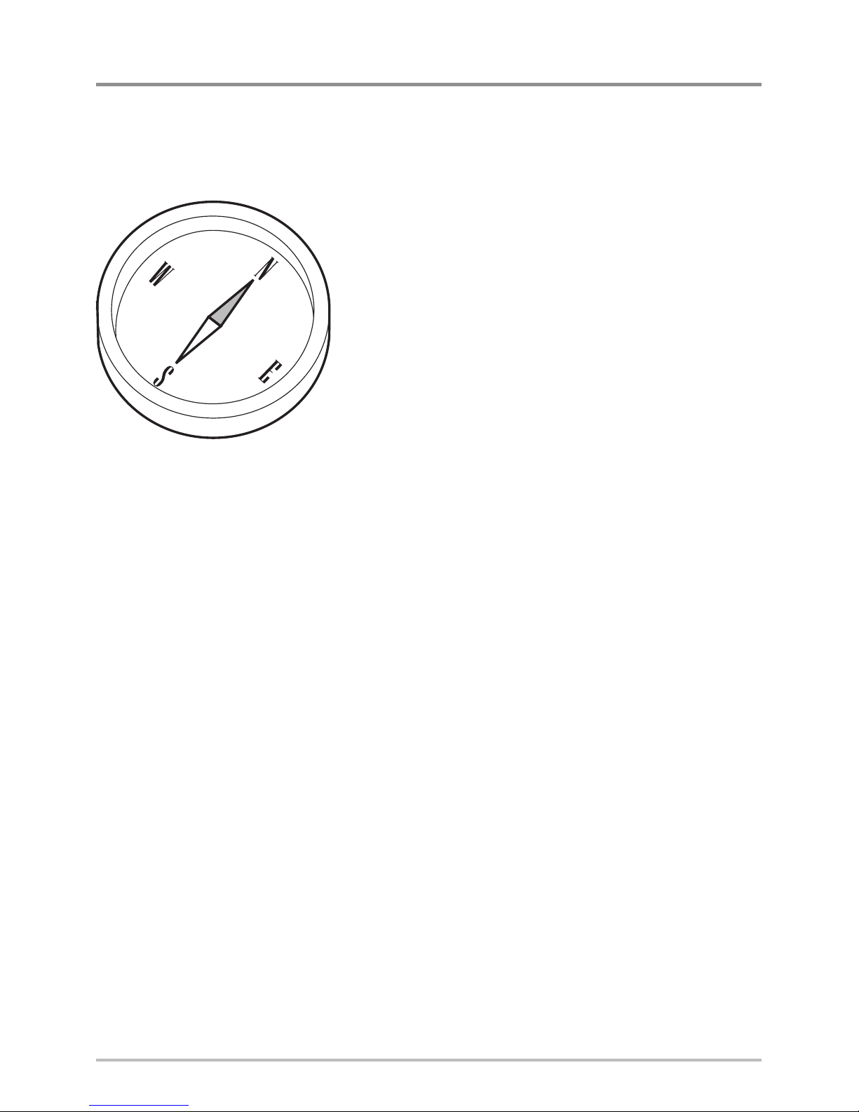
How the Heading Sensor Works
The magnetic compass is one of the first known instruments for navigation. It
relies on the earth’s magnetic field to align a magnetic pointer towards North,
also known as Magnetic North.
If your accessory includes a Heading Sensor, the
control head will display the heading from the
internal compass in digital format. The Heading is
the direction the boat is pointing, where 000° is
North, 090° is East, 180° is South, and 270° is
West.
Due to wind and waves, the boat is often
traveling in a slightly different direction than its
heading. The direction of travel, or Course Over
Ground, is provided by the GPS receiver. You can
use the compass Heading with the GPS Course
Over Ground and Bearing to navigate a route.
A compass’ Magnetic North is affected by the local variations in the earth’s
magnetic field around the globe. Nautical charts will often provide the
magnetic declination, or magnetic variation, for a local area so that you can
confirm that Magnetic North matches True North. If you have trailered the boat
to a new location, the compass’ operation may also be affected by a different
magnetic zone. The Humminbird® control head compensates for magnetic
declination and also allows you to make additional adjustments from the menu
system. The details of these features are described in this manual.
3
Overview

Installation Overview
Use the following instructions to install the Sensor accessory on your boat. In
order to understand the installation requirements, we recommend that you
read the instructions carefully before you start the installation.
Required Supplies: In addition to the hardware included with your
Sensor accessory kit, you will need a drill, electrical tape, and an awl or
pencil. Depending on your installation requirements, you might also
need to purchase extention cables or a stem. See Section 1: Choose
the Mounting Location for more information.
1. Choose the Mounting Location
It is important to consider the following information when you choose a
mounting location for the Sensor:
• Interference: Do NOT mount the Sensor close to a VHF antenna or
within the active area of a radar. If the Sensor includes a compass
(AS GPS HS), do NOT install it near ferrous metals or near anything that
can create a magnetic field. Hardware and cables that handle large
currents, such as batteries and power cables, are also examples of
equipment that may cause interference.
• Reception: Mount the Sensor in an area that has full exposure to the
sky. The effective area of reception is 5˚ above the horizon.
• Surface: Whether the Sensor Cable will be routed down through the
mounting surface or to the side, or if your’re using a stem mount, the
mounting surface will influence how you install the Sensor. For details,
see Section 2: Install the Sensor.
• Cables: Test run the Sensor Cable from the chosen mounting location to
the Control Head. 10 ft (3m) extension cables may be purchased from
Humminbird® if your planned cable route exceeds 20 ft (6 m). Maximum
cable length, including extension cables, should not exceed 50 ft (16 m).
NOTE: To purchase extension cables, or other related accessories, visit our Web
site at humminbird.com or call our Customer Resource Center at
1-800-633-1468.
4
Installation Overview
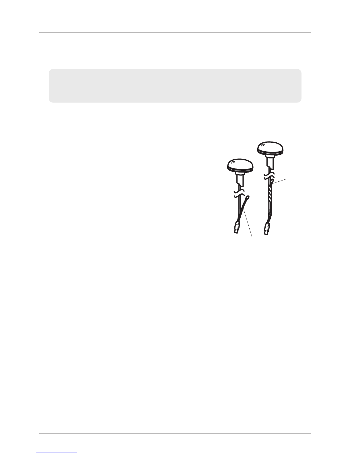
2. Install the Sensor
There are three different options to mount the sensor. Proceed to the section
that matches the type of mounting location you will be using, as follows:
Stem
Cable routed through the hole
Cable routed to the side
Stem Mount with 1” - 14 Thread
The sensor will be mounted on a stem or
antenna pole. Proceed to Section A.
Access Under the Mounting Deck
The sensor will be deck mounted and the
cable can be routed down through the
mounting surface. Proceed to Section B.
NO Access Under the Mounting Deck
The sensor will be deck mounted and the
cable must routed to the side because
there is not space for a cable through or
underneath the mounting location.
Proceed to Section C.
5
Installation- Overview
A. Stem Mount with 1”-14 Thread
Use the following instructions to stem mount the Sensor:
1. If you have a pre-existing stem mount, skip
to step 2.
If you need to mount the antenna pole
(stem), mark the chosen mounting location
and drill a 3/4” (19 mm) hole for the cable
and cable connector.
If you have purchased hardware to stem
mount your Sensor, follow the instructions
included with that hardware to attach the
stem to the boat.
2. Screw the sensor base onto the stem first,
making sure that the stem pipe does not
protrude from the sensor base. (This adds
protection to the cable when it is pulled
through the pipe stem.) Deburr the pipe
edges to reduce cable abrasion.
3. Use electrical tape to secure the NMEA
pigtail to the cable.
NOTE: Unless it is needed, leave the NMEA pigtail
secured to the cable. If you are connecting the pigtail
to a NMEA 0183 device, see Section 3: Connect to
the Control Head for connection information.
Stem Mount, Attaching the
Sensor Base to the Stem
Base
Cover
Stem
Taping the NMEA Pigtail
to the Cable
NMEA
Pigtail
Cable
Taped
NMEA Pigtail Cable Out
WARNING! If your Sensor includes a compass (AS GPS HS), do NOT mount it
to a stem mount or antenna pole that contains ferrous metals.
NOTE: It is important to review the mounting considerations and test run the
cable route as indicated in Section 1 before proceeding with the installation.
6
Installation- Stem Mount
4. Route the Sensor cable through the stem and
through the planned cable route. To use
extension cables, see the details in
Section 1: Choose the Mounting Location.
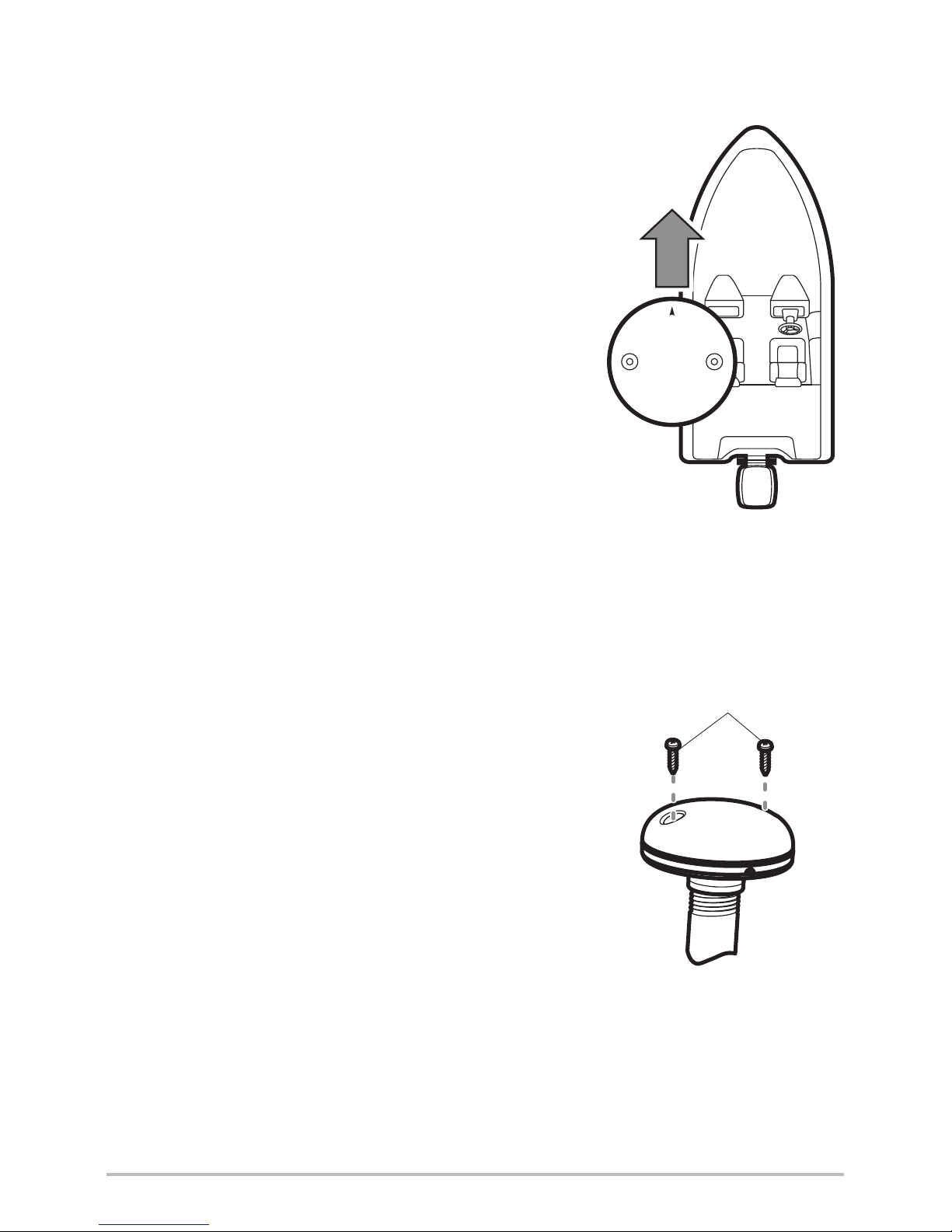
5. If the Sensor includes a compass
(AS GPS HS), position the sensor so the
arrow on the cover is pointed straight toward
the front of the boat in the direction of travel.
The arrow should be parallel with the keel.
NOTE: Failure to align the sensor correctly will
result in incorrect compass readings.
6. Attach the Sensor to its base using the
included #6 -1/4” screws. Hand tighten only.
Positioning the Arrow
on the Compass
Attaching the Sensor
to the Base
#6 -1/4
Mounting Screws
7
Installation- Stem Mount
B. Access Under Mounting Location
Use the following instructions to deck mount the Sensor and route the cable
down through the mounting surface:
1. Mark the mounting location and drill a 3/4”
(19mm) hole for the cable and cable connector.
2. Secure the NMEA pigtail to the cable with
electrical tape.
NOTE: Unless it is needed, leave the NMEA pigtail
secured to the cable. If you are connecting the pigtail
to a NMEA 0183 device, see Section 3: Connect to
the Control Head for connection information.
3. Route the Sensor cable through the planned
cable route. To use extension cables, see the
details in Section 1: Choose the Mounting
Location.
4. Cover the cable hole with the Sensor.
If the Sensor includes a compass
(AS GPS HS), position the sensor so the
arrow on the cover is pointed straight toward
the front of the boat in the direction of travel.
The arrow should be parallel with the keel.
NOTE: Failure to align the sensor correctly will
result in incorrect compass readings.
5. Make sure the Sensor is flush against the
surface, and mark the two mounting holes
with a pencil or awl.
Taping the NMEA Pigtail
to the Cable
NMEA
Pigtail
Cable
Taped
NMEA Pigtail Cable Out
NOTE: It is important to review the mounting considerations and test run the
cable route as indicated in Section 1 before proceeding with the installation.
8
Installation - Access Under
6. Move the Sensor to the side and drill two pilot holes, using a 5/32”
(4 mm) bit.
NOTE: Apply marine-grade silicone caulk or sealant to both screw and drilled
holes as needed to protect your boat from water damage.
7. Align the Sensor’s screw holes over the pilot screw holes and attach
with the #6 - 3/4” Phillips head screws. Hand tighten only.
NOTE: If the mounting surface is thin or made of a light-weight material, you
may need to add reinforcing material below the mounting surface in order to
support the Sensor.
Positioning the Arrow
on the Compass
Attaching the Sensor to the
Mounting Surface
Cable routed through the hole
#6 - 3/4
Mounting Screws
9
Installation - Access Under
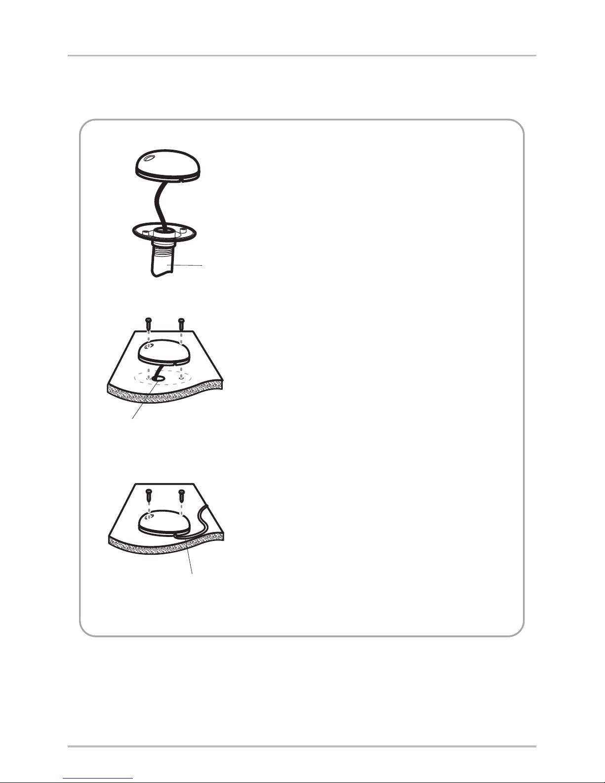
C. No Access Under Mounting Location
Use the following instructions to deck mount the Sensor and route the cable to
the side if there is not space for a cable underneath the mounting location.
1. Secure the NMEA pigtail with electrical tape.
NOTE: Unless it is needed, leave the NMEA pigtail
secured to the cable. If you are connecting the pigtail
to a NMEA 0183 device, see Section 3: Connect to
the Control Head for connection information.
2. Route the cable from the Sensor to the
Control head.
• The Sensor has two wire routing
notches. Use the cable notch closest to
the intended cable route.
• If holes are required to route the cable,
they must be 3/4” (19mm) to allow for
the cable connector.
• To use extension cables, see the details
in Section 1: Choose the Mounting
Location.
Taping the NMEA Pigtail
to the Cable
NMEA
Pigtail
Cable
Taped
NMEA Pigtail Cable Out
NOTE: It is important to review the mounting considerations and test run the
cable route as indicated in Section 1 before proceeding with the installation.
10
Installation - NO Access Under
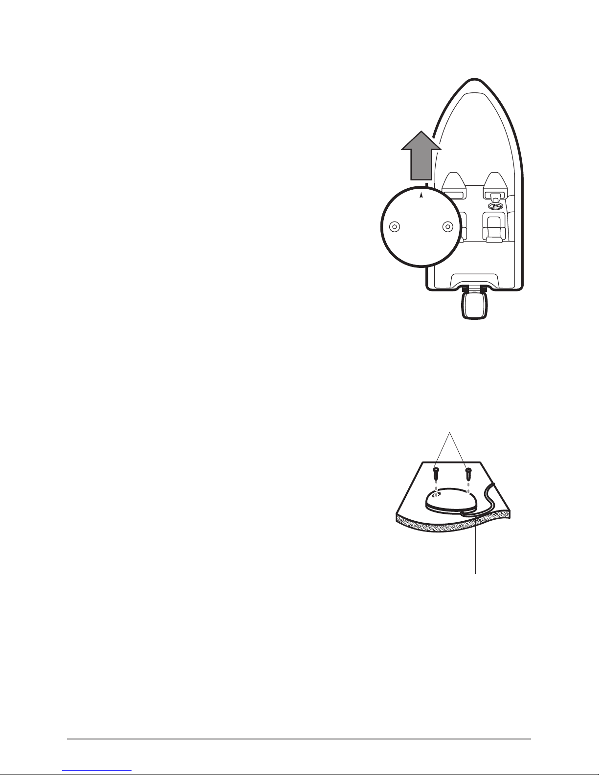
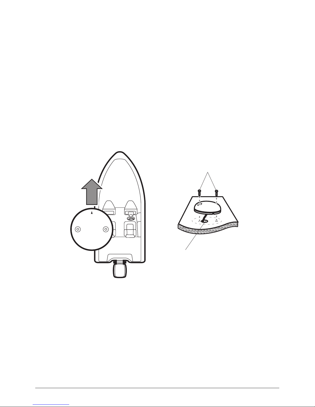
3. With the cable routed, position the Sensor in
the planned mounting location.
If the Sensor includes a compass
(AS GPS HS), position the sensor so the
arrow on the cover is pointed straight toward
the front of the boat in the direction of travel.
The arrow should be parallel with the keel.
NOTE: Failure to align the sensor correctly will result
in incorrect compass readings.
4. Make sure the Sensor is flush against the
surface, and mark the two mounting holes
with a pencil or awl.
5. Move the Sensor to the side and drill the two
5/32” (4 mm) pilot holes.
NOTE: Apply marine-grade silicone caulk or sealant
to both screw and drilled holes as needed to protect
your boat from water damage.
6. Align the Sensor’s screw holes over the pilot
screw holes and attach with the
#6 - 3/4” Phillips head screws. Hand tighten
only.
Positioning the Arrow
on the Compass
Attaching the Sensor to the
Mounting Surface
Cable routed to the side
#6 - 3/4
Mounting Screws
11
Installation - NO Access Under

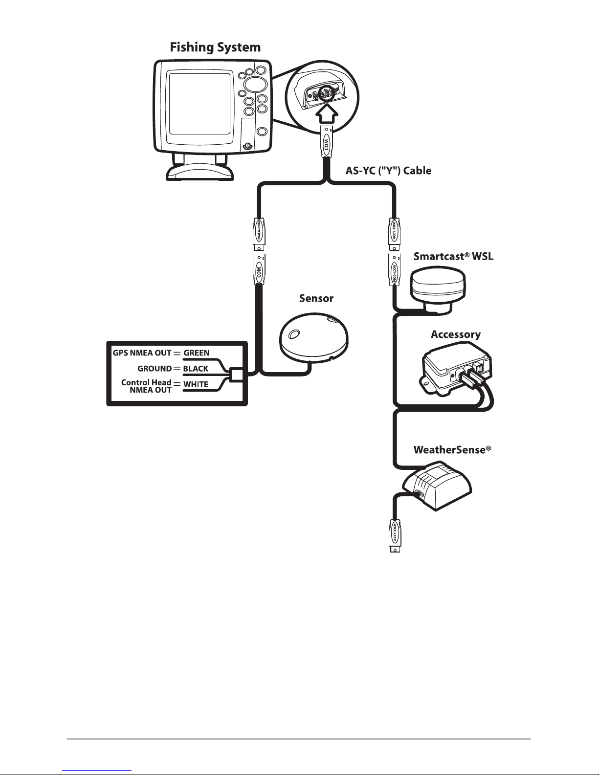
3. Connect to the Control Head
Use the following instructions to connect the Sensor cable to the control head.
1. Insert the Sensor’s NMEA-COM connector into the control head’s
COM port. The connectors are keyed to prevent reversed installation,
so be careful not to force the connector into the port.
• If there is another accessory plugged into the COM port, you will
need to install the AS YC ("Y") cable so that you can use the
accessories at the same time.
• Attach the COM connector of the "Y" cable directly to the control
head COM port. Connect the Sensor to the NMEA-COM connector
of the "Y" cable. Re-connect your other Fishfinder accessories to
the ACCY-COM connector of the "Y" cable.
2. Optional: The control head outputs NMEA signals through the
Sensor’s pigtail cable for connection to a device such as an autopilot.
Connect the NMEA Out (White Wire) of the cable to the NMEA In of
the device you are connecting to your Fishfinder. The pinouts of this
cable are as follows:
• Green Wire, GPS NMEA Out
• Black Wire, Ground
• White Wire, Control Head NMEA Out
WARNING! It is important to finish all installation connections before powering
on the control head.
12
Installation
13
Installation
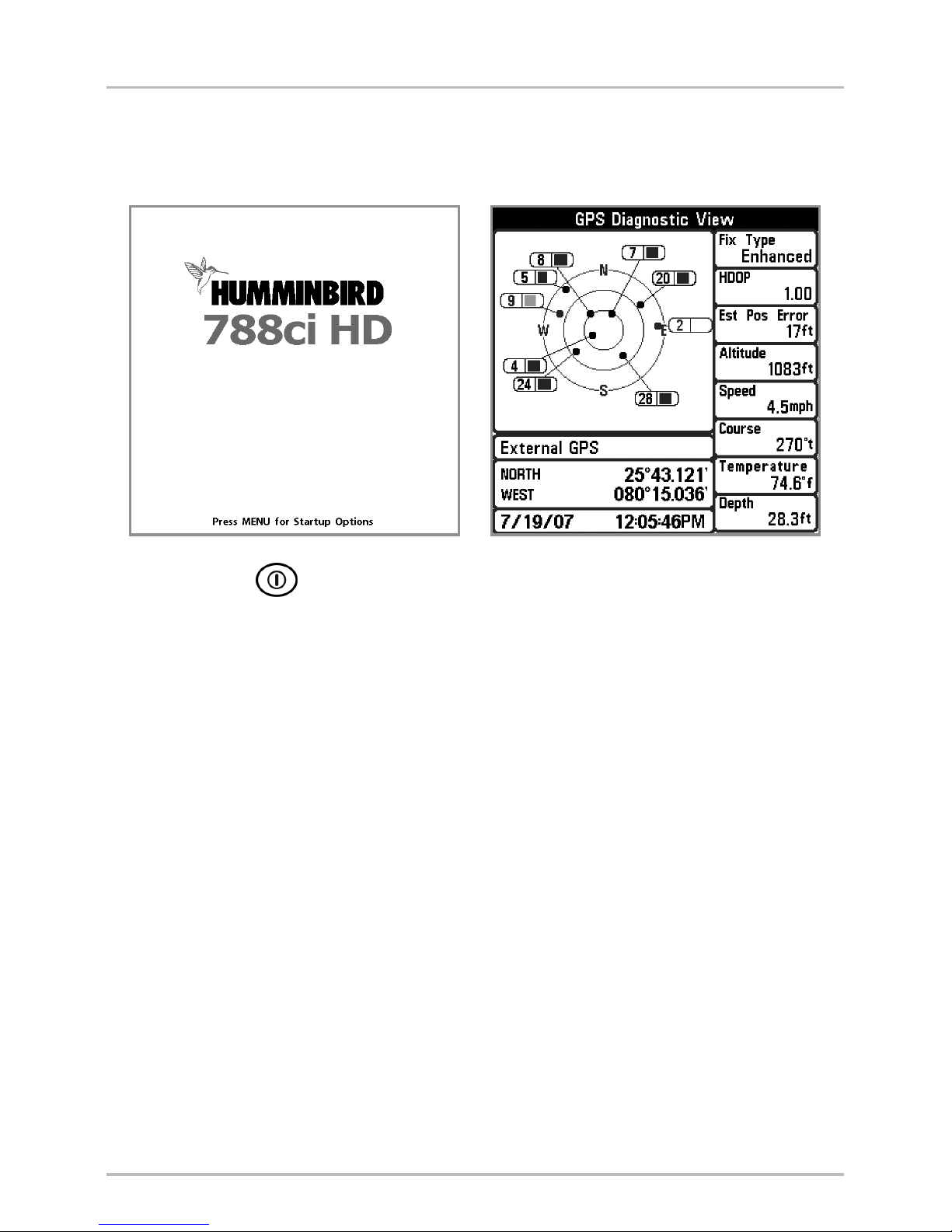
4. Power on and Confirm GPS Reception
Follow the instructions below to power on your Humminbird® control head.
1. Press the POWER/LIGHT key.
2. When the Title screen is displayed, press the MENU key to access the
Start-Up Options Menu.
3. If a functioning transducer is connected, Normal operation will be
selected automatically, and your Fishing System can be used on the
water. See Start-Up Options Menu for more information.
4. Press the VIEW key until the GPS Diagnostic View is displayed on the
screen. Confirm that External GPS is displayed and the Fix Type indicates
Enhanced or 3D.
• If the GPS Diagnostic View is not displayed in the rotation, press
the MENU key twice to open the Main Menu. Select the
Views tab > GPS Diagnostic View > Visible.
• If it is connected and detected, the Sensor will also be displayed
in the Accessory Test screen (see Start-Up Options Menu).
788ci HD Title Screen GPS Diagnostic View
14
Installation

5. Confirm the Baud Rate (for devices connected to the pigtail only)
If there is an accessory, such as an autopilot, connected to the Sensor pigtail
cable wires, you will need to confirm that the devices are communicating at
the same baud rate. The baud rate details are as follows:
• If the GPS Receiver/Heading Sensor (AS GPS HS) is connected to
the control head, and NMEA Output is turned on, the control head will
operate exclusively at a baud rate of 38400. If there is an accessory
attached to the Sensor’s pigtail, it also needs to operate at 38400. See
your accessory installation guide to set the baud rate to 38400.
• If a GPS Receiver (AS GR16, AS GR50, AS GRP) is connected to the
control head, and NMEA Output is turned on, the control head will
operate exclusively at a baud rate of 4800. If there is an accessory
attached to the Sensor’s pigtail, it also needs to operate at 4800. See
your accessory installation guide to set the baud rate to 4800.
• If NMEA Output is turned off, then baud rates 4800, 9600, and 38400
are available on the control head and no further action is required.
Turn On/Off NMEA Output
1. Press the MENU key twice.
2. Select Setup tab > NMEA Output.
3. Press the RIGHT or LEFT Cursor keys to select On or Off. (Default = Off)
NOTE: The menu option in your Fishing System will be called NMEA 0183 Output or
NMEA Output. If the menu option is not shown under the Setup tab, make sure the
User Mode is set to Advanced (Setup tab > User Mode > Advanced). See Setup Menu
Tab: NMEA Output for more information.
15
Installation

6. Confirm the Heading Sensor Operation
(Heading Sensors only [AS GPS HS])
It is important to confirm that the Heading Sensor is installed correctly by
reviewing the heading digital readout.
NOTE: This procedure should be performed at slow speeds, in calm, open water, in a
large area that is far from shallow water, boats, or other obstacles.
1. Press the MENU key twice to open the Main Menu.
2. Select Navigation tab > North Reference > Magnetic.
3. Press the EXIT key.
4. Select Setup tab > Select Readouts.
NOTE: If the Select Readouts menu option does not appear under the Setup
tab, change the User Mode to Advanced. Select Main Menu > Setup tab >
User Mode > Advanced.
5. Select a Readout position and use the RIGHT or LEFT Cursor keys to
select Heading. Select another Readout position and select Course.
6. Press the EXIT key until the Main Menu is closed.
7. Press the VIEW key until the Sonar View is displayed on the screen.
8. Navigate the boat in a straight line, in calm, open water at 4.5 mph.
Compare the Heading digital readout on the screen with the Course
(COG) digital readout. The readouts should be within approximately 5°
of each other.
Adjust: To adjust the zero point of the Heading Sensor, select Main
Menu > Navigation tab > Heading Offset. Press the RIGHT or
LEFT Cursor keys to adjust the setting.
If the procedure failed: If the Heading digital readout is
significantly different than the COG, the Heading Sensor might be
installed in a location with too much magnetic interference. Check
the installation location and possible magnetic disturbances in the
area.
16
Installation
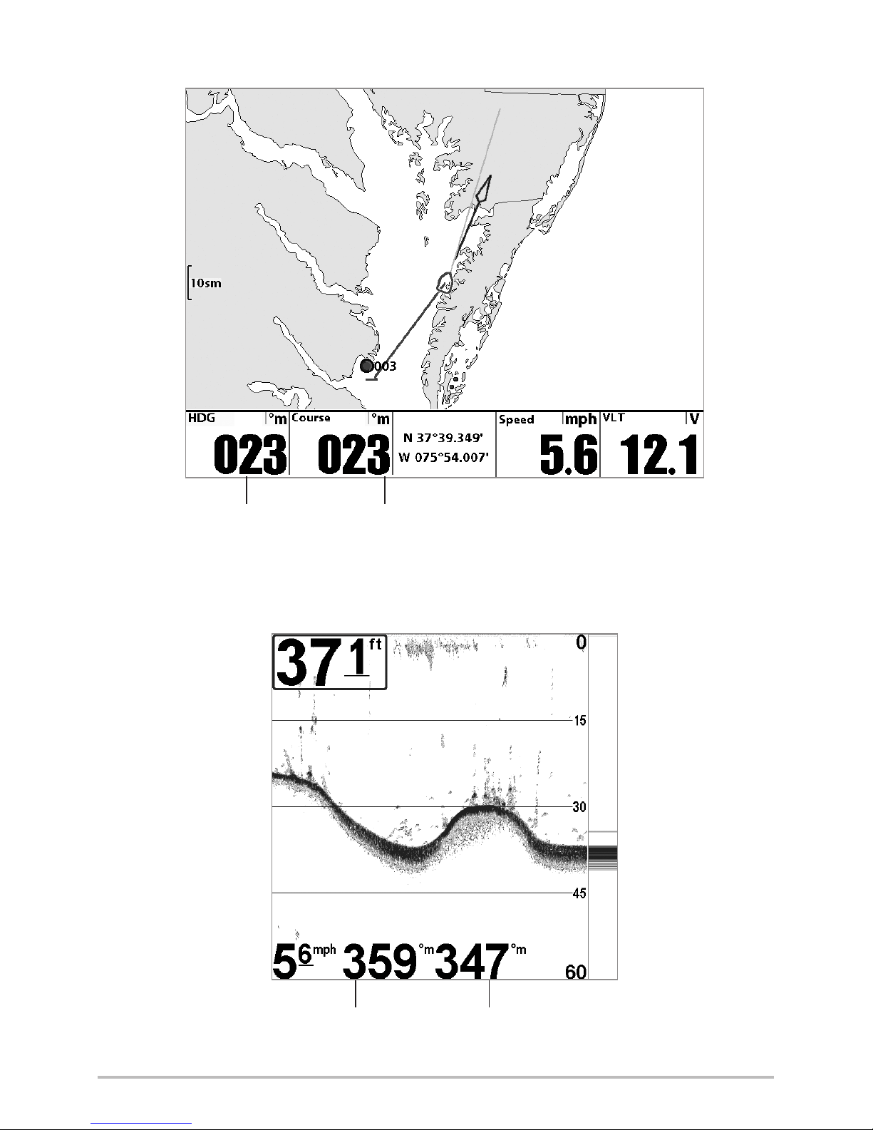
Heading
(Heading Sensor Required)
Course
(GPS Required)
Confirming the Heading Digital Readout
(788ci HD, Sonar View)
Course
(GPS Required)
Confirming the Heading Digital Readout (1198c SI, Chart View)
Heading
(Heading Sensor Required)
17
Installation
 Loading...