

Humminbird 531427-1-D User Manual
767 GPS Chartplotter
767 GPS Chartplotter
Operations Manual
Operations Manual
531427-1_D

Thank You!
Thank you for choosing Humminbird®, America's #1 name in fishfinders. Humminbird® has
built its reputation by designing and manufacturing top-quality, thoroughly reliable marine
equipment. Your Humminbird® is designed for trouble-free use in even the harshest marine
environment. In the unlikely event that your Humminbird® does require repairs, we offer an
exclusive Service Policy - freeof charge during the first year after purchase, and available at a
reasonablerateaftertheone-yearperiod. Forcompletedetails, see theseparatewarranty card
included with your unit.Weencourageyoutoreadthis operations manualcarefullyin orderto
get fullbenefit from allthefeaturesand applicationsofyourHumminbird®product.
Contact our Customer Resource Center at either 1-800-633-1468 or visit our website at
www.humminbird.com.
WARNING! This deviceshould not be used as a navigational aid to preventcollision,grounding,
boatdamage,orpersonalinjury.When theboatis moving,water depthmay changetoo quickly
toallow timefor youtoreact. Always operate theboatat veryslowspeedsifyou suspectshallow
waterorsubmerged objects.
WARNING! Disassembly and repair of this electronic unit should only be performed by
authorized service personnel. Any modification of the serial number or attempt to repair the
original equipment or accessoriesbyunauthorized individuals will void the warranty. Handling
and/oropening thisunitmayresult in exposuretolead, in the form of solder.
WARNING! This product contains lead, a chemical known to the state of California to cause
cancer, birth defectsandother reproductive harm.
DualBeam PLUSTM,FishID+TM,FishingGPS®, Humminbird®,HumminbirdPCTM,QuadraBeamTM,RTS®Window,
Selective Fish ID+TM, WeatherSense®, WhiteLine®, WideSide®, X-PressTMMenu, and Structure ID® are
trademarkedby or registeredtrademarksofHumminbird®.
© 2008 Humminbird®,Eufaula AL,USA. All rights reserved.
i

Table of Contents
How Sonar Works 1
DualBeam PLUS™ Sonar ............................................................................................................................................ 3
QuadraBeam™ Sonar (with optional-purchase QuadraBeam™ transducer) ............................................ 3
WideSide® Sonar (with optional-purchase WideSide® transducer) ............................................................ 4
How GPS and Cartography Work 5
Multi-Media Card (MMC)/SD Slot 6
Software Updates ........................................................................................................................................................ 6
What’s On the Display 7
Views 9
Sonar View.................................................................................................................................................................... 10
Understanding Sonar History ................................................................................................................................ 11
Real Time Sonar (RTS®) Window............................................................................................................................ 11
Freeze Frame ................................................................................................................................................................ 12
Bottom Presentation ................................................................................................................................................ 12
Sonar Zoom View ...................................................................................................................................................... 14
200/83 kHz Split Sonar View ................................................................................................................................ 15
Big Digits View ............................................................................................................................................................ 15
Circular Flasher View ................................................................................................................................................ 16
Screen Snapshot View .............................................................................................................................................. 16
Side Beam View (with optional-purchase QuadraBeam™ transducer) .................................................... 17
WideSide® View (with optional-purchase WideSide® transducer).............................................................. 19
Bird's Eye View............................................................................................................................................................ 20
Chart View .................................................................................................................................................................... 21
Combo View ................................................................................................................................................................ 22
View Orientation........................................................................................................................................................ 22
Viewing Cartography 23
Introduction to Navigation 24
Waypoints, Routes and Tracks .............................................................................................................................. 24
Save, Edit or Delete a Waypoint............................................................................................................................ 25
Navigate to a Waypoint or Position .................................................................................................................... 26
Add a Waypoint Target or Trolling Grid ............................................................................................................ 27
Save, Edit or Delete a Route .................................................................................................................................. 28
Save or Clear a Current Track ................................................................................................................................ 28
Edit, Delete or Hide Saved Tracks ........................................................................................................................ 29
ii

Table of Contents
Key Functions 29
POWER/LIGHT Key .................................................................................................................................................. 29
VIEW Key ...................................................................................................................................................................... 30
INFO Key........................................................................................................................................................................ 30
MENU Key .................................................................................................................................................................... 30
4-WAY Cursor Control Key ...................................................................................................................................... 31
MARK Key ...................................................................................................................................................................... 31
GOTO Key ...................................................................................................................................................................... 31
ZOOM (+/-) Key .......................................................................................................................................................... 32
EXIT Key ........................................................................................................................................................................ 32
Accessory Bus 32
Powering Up the Unit 33
The Menu System 34
Start-Up Options Menu 36
Normal Operation...................................................................................................................................................... 36
Simulator .................................................................................................................................................................... 36
System Status ............................................................................................................................................................ 37
Self Test.......................................................................................................................................................................... 37
Accessory Test.............................................................................................................................................................. 37
GPS Diagnostic View ................................................................................................................................................ 38
PC Connect (with PC Connect cable only) .......................................................................................................... 38
Sonar X-Press™ Menu (Sonar views only) 39
Side (WideSide® transducer: WideSide® view only) ........................................................................................ 40
Sensitivity .................................................................................................................................................................... 41
Upper Range (Advanced: Sonar, Split Sonar, Big Digits and Circular Flasher views only) .................. 42
Lower Range ................................................................................................................................................................ 43
Side Beam Range (WideSide® transducer: WideSide® view only) .............................................................. 44
Chart Speed ................................................................................................................................................................ 44
Bottom View................................................................................................................................................................ 45
Bottom Range (Sonar Zoom view only when Bottom Lock is On) .............................................................. 45
Bottom Lock (Sonar Zoom view only).................................................................................................................. 46
Cancel Navigation (only when navigating) ...................................................................................................... 46
iii

Table of Contents
Navigation X-Press™ Menu (Navigation views only) 47
Waypoint [Name] (Only with an active cursor on a waypoint).................................................................. 48
Cursor To Waypoint (Chart or Combo view only)............................................................................................ 49
Save Current Track .................................................................................................................................................... 49
Clear Current Track.................................................................................................................................................... 49
Save Current Route (only when navigating) .................................................................................................... 50
Skip Next Waypoint (only when navigating) .................................................................................................. 50
Cancel Navigation (only when navigating) ...................................................................................................... 50
Remove Target (only if Target is Active) ............................................................................................................ 51
Remove Grid (only if Grid is Active) ...................................................................................................................... 51
Sonar Window (Combo view only)........................................................................................................................ 51
Waypoint [Name] (Most recently-created waypoint) .................................................................................... 52
Screen Snapshot X-Press™ Menu (Screen Snapshot view only) 53
Delete Image (optional-purchase MMC/SD card only).................................................................................. 53
Delete All Images (optional-purchase MMC/SD card only) ........................................................................ 53
Sonar Menu Tab 54
Beam Select ................................................................................................................................................................ 55
TM
Fish ID+
...................................................................................................................................................................... 56
Fish ID Sensitivity ...................................................................................................................................................... 57
Real Time Sonar (RTS®) Window .......................................................................................................................... 57
Zoom Width ................................................................................................................................................................ 58
83 kHz Sensitivity (Advanced)................................................................................................................................58
455 kHz Balance (Advanced, with QuadraBeam
WideSide® Sensitivity (Advanced, with WideSide® transducer)s .............................................................. 59
Depth Lines (Advanced) .......................................................................................................................................... 60
Surface Clutter (Advanced)...................................................................................................................................... 61
Noise Filter (Advanced) ............................................................................................................................................ 62
Max Depth (Advanced) ............................................................................................................................................ 62
Water Type (Advanced)............................................................................................................................................ 63
Transducer Select ...................................................................................................................................................... 63
Navigation Menu Tab 64
Current Track .............................................................................................................................................................. 65
Saved Tracks ................................................................................................................................................................ 65
Waypoints.................................................................................................................................................................... 66
Routes ............................................................................................................................................................................ 67
TM
transducer) .................................................................. 58
iv

Table of Contents
Chart Orientation ...................................................................................................................................................... 67
North Reference.......................................................................................................................................................... 68
Grid Rotation .............................................................................................................................................................. 68
Trackpoint Interval .................................................................................................................................................... 68
Track Min Distance (Advanced) ............................................................................................................................ 69
Map Datum (Advanced) .......................................................................................................................................... 69
Course Projection Line .............................................................................................................................................. 70
Export All Nav Data (Advanced) ............................................................................................................................ 70
Delete All Nav Data (Advanced) ............................................................................................................................ 70
Chart Menu Tab 71
Chart Detail Level........................................................................................................................................................ 72
Map Borders ................................................................................................................................................................ 72
Lat/Lon Grid ................................................................................................................................................................ 73
Spot Soundings ............................................................................................................................................................73
Set Simulation Position (Advanced) .................................................................................................................... 73
Set Map Offset (Advanced) .................................................................................................................................... 74
Clear Map Offset (Advanced).................................................................................................................................. 74
Alarms Menu Tab 75
Depth Alarm ................................................................................................................................................................ 76
Fish ID Alarm................................................................................................................................................................ 76
Low Battery Alarm...................................................................................................................................................... 77
Temp Alarm.................................................................................................................................................................. 77
Off Course Alarm ...................................................................................................................................................... 78
Arrival Alarm .............................................................................................................................................................. 78
Drift Alarm .................................................................................................................................................................. 79
Alarm Tone .................................................................................................................................................................. 79
Setup Menu Tab 80
Units - Depth ................................................................................................................................................................ 81
Units - Temp (International only) .......................................................................................................................... 81
Units - Distance............................................................................................................................................................ 81
Units - Speed ................................................................................................................................................................ 82
User Mode .................................................................................................................................................................... 82
Language (International only)................................................................................................................................82
Triplog Reset .............................................................................................................................................................. 83
Restore Defaults ........................................................................................................................................................ 83
Select Readouts (Advanced, Sonar view only) .................................................................................................. 84
v

Table of Contents
Depth Offset (Advanced) ........................................................................................................................................ 85
Temp Offset (Advanced).......................................................................................................................................... 85
Speed Calibration (Advanced, with Temp/Speed only) ................................................................................ 85
Local Time Zone (Advanced) .................................................................................................................................. 86
Daylight Saving Time (Advanced) ........................................................................................................................ 86
Position Format (Advanced) .................................................................................................................................. 87
Time Format (Advanced, International only) .................................................................................................... 87
Date Format (Advanced, International only) .................................................................................................... 87
NMEA Output (Advanced) ...................................................................................................................................... 88
Sonar .............................................................................................................................................................................. 88
Views Menu Tab 89
Accessories Menu Tab 90
Using Screen Snapshot............................................................................................................................................ 90
Troubleshooting 92
700 Series™ Doesn’t Power Up ............................................................................................................................ 92
700 Series™ Defaults to Simulator with a Transducer Attached.............................................................. 92
Display Problems........................................................................................................................................................ 93
Finding the Cause of Noise .................................................................................................................................... 94
700 Series™ Fishing System Accessories 95
Specifications 96
Glossary 97
Sonar Terms............................................................................................................................................................ 97
GPS & Navigation Terms .................................................................................................................................. 105
Contact Humminbird® 110
NOTE: Entries in this Table of Contents which list (International only) are only available on
products sold outside of the U.S. by our authorized International Distributors. To obtain a list of
authorized International Distributors, please visit our website at www.humminbird.com or
contact our Customer Resource Center at
NOTE: Entries in this Table of Contents which list (with PC Connect Cable Only) or (with OptionalPurchase QuadraBeam
purchase of separate accessories. You can visit our website at www.humminbird.com to order
these accessories online or contact our Customer Resource Center at
TM
/WideSide® Transducer) or (with Temp/Speed Only) require the
1-800-633-1468
vi
to locate the distributor nearest you.
1-800-633-1468
.
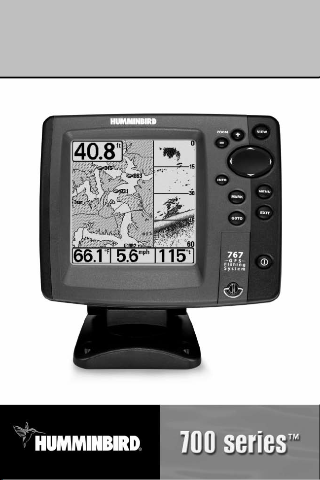
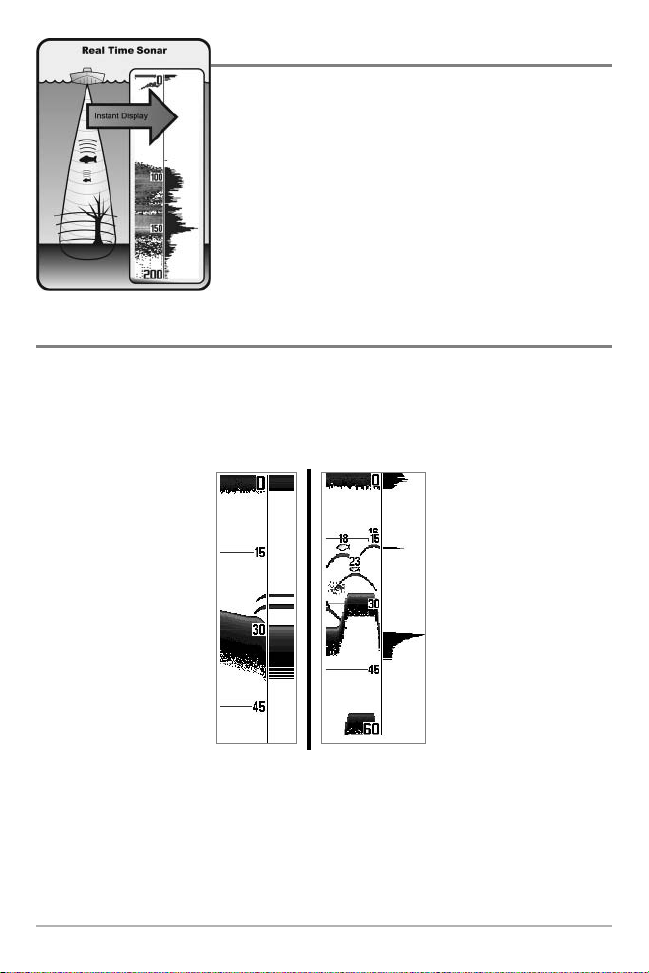
How Sonar Works
Sonar technology is based on sound waves. The 700 Series™ Fishing System uses sonar to
locate and define structure, bottom contour and composition, as well as depth directly below
the transducer.
Your 700 Series™ Fishing System sends a sound wave signal and determines distance by
measuring the time between the transmission of the sound wave and when the sound wave is
reflected off of an object; it then uses the reflected signal to interpret location, size, and
composition of an object.
Sonar is very fast. A sound wave can travel from the surface to a depth of 240 ft
(70 m) and back again in less than 1/4 of a second. It is unlikely that your boat can "outrun"
this sonar signal.
SONAR is an acronym for SOund and NAvigation Ranging.
Sonar utilizes precision sound pulses or "pings" which are
emitted into the water in a teardrop-shaped beam.
The sound pulses "echo" back from objects in the water such
as the bottom, fish and other submerged objects. The
returned echoes are displayed on the LCD screen. Each time a
new echo is received, the old echoes are moved across the LCD,
creating a scrolling effect.
When all the echoes are viewed side by side, an easy to
interpret "graph" of the bottom, fish and structure appears.
1
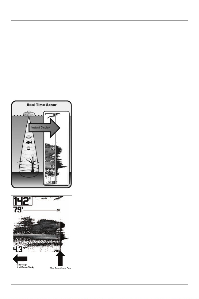
The sound pulses are transmitted at various frequencies
depending on the application. Very high frequencies (455kHz)
are used for greatest definition but the operating depth is
limited. High frequencies (200kHz) are commonly used on
consumer sonar and provide a good balance between depth
performance and resolution. Low frequencies (83kHz) are
typically used to achieve greater depth capability.
The power output is the amount of energy generated by the
sonar transmitter. It is commonly measured using two
methods:
• Root Mean Square (RMS) measures power output over
the entire transmit cycle.
• Peak to Peak measures power output at the highest
points.
The benefits of increased power output are the ability to
detect smaller targets at greater distances, ability to
overcome noise, better high speed performance and
enhanced depth capability.
2
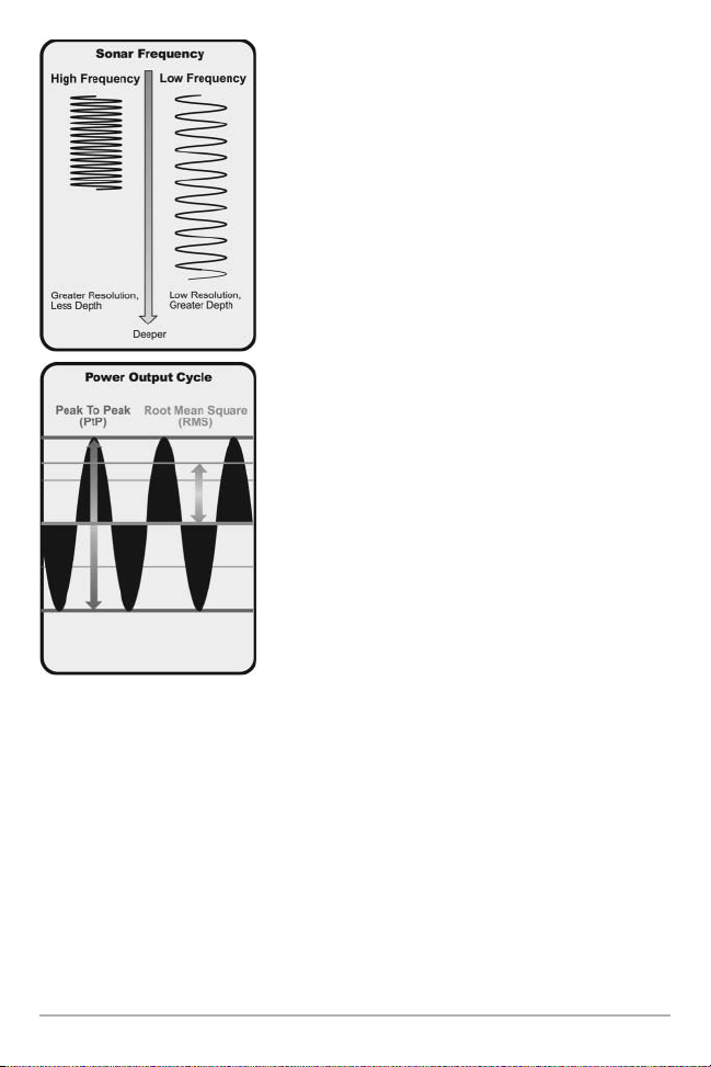
DualBeam PLUS™ Sonar
90° Total Coverage
Bottom Coverage=2 x Depth
35° 60° 20° 35°
455 kHz 455 kHz
83 kHz
200 kHz
Your 700 Series™ Fishing System uses a 200/83 kHz DualBeam
PLUS™ sonar system with a wide (60°) area of coverage.
DualBeamPLUS™sonarhasanarrowlyfocused20°centerbeam,
surrounded by a second beam of 60°, expanding your coverage
to an area equal to your depth. In 20 feet of water, the wider
beam covers an area 20 feet wide. DualBeam PLUS™ sonar
returns can beblendedtogether,viewed separately orcompared
side-by-side. DualBeam PLUS™ is ideal for a wide range of
conditions - from shallow to very deep water in both fresh and
salt water. Depth capability is affected by such factors as boat
speed, wave action, bottom hardness, water conditions and
transducerinstallation.
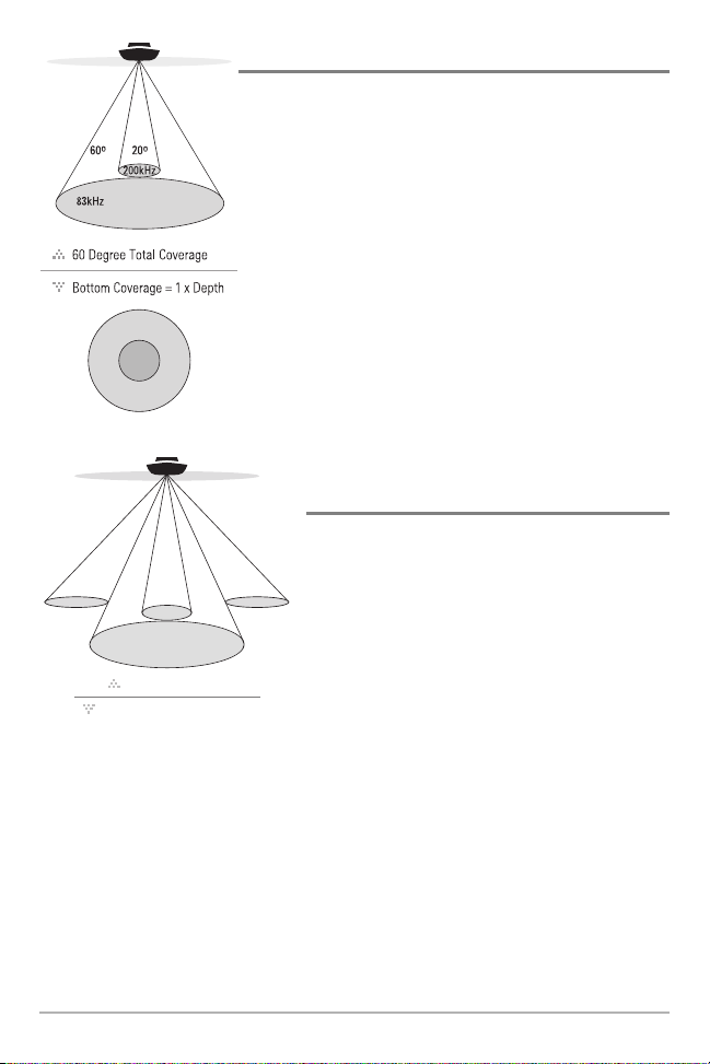
QuadraBeam™ Sonar
(withoptional-purchaseQuadraBeamTMtransducer)
Your 700 Series™ Fishing System also supports
QuadraBeam™ sonar with the purchase of an
additional QuadraBeam™ transducer. QuadraBeam™
sonar provides an extremely wide 90° area of
coverage. QuadraBeam™ starts with two 45° 455 kHz
beams for a continuous 90° of uninterrupted side to
side coverage to 160 feet. These Side Structure
locating beams reveal fish and structure to the left
and right of your boat near the bottom. For structure
directly below your boat, Quadrabeam™ uses
DualBeam PLUS™ technology.
3
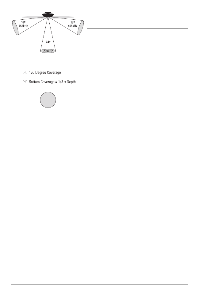
WideSide® Sonar
(withoptional-purchaseWideSide®transducer)
Your 700 Series™ Fishing System also supports
WideSide® sonar with the purchase of an additional
WideSide® transducer. The WideSide® transducer is a
specialized "side-looking" transducer that is extremely
useful for bank fishing or looking for bait fish in open
water. The WideSide® transducer uses three different
sonar elements that transmit signals to the left, right
and straight down from your boat. The downward
beamis200kHz with a24° area of coverage. This beam
maintains acontinuous digital depth readout from the
bottom directly beneathyourboat. Thesidebeams are
455 kHz with a 16° area of coverage. The side-looking
elements can be used independently, or together to
locate targets near the surface of the water on either
sideof your boat.
4

How GPS and Cartography Work
Your 700 Series™ Fishing System also supports GPS and chartplotting, and uses GPS and sonar
to determine your position, display it on a grid, and provide detailed underwater information.
The Global Positioning System (GPS) is a satellite navigation system designed and maintained
by the U.S. Department of Defense. GPS was originally intended for military use; however,
civilians may also take advantage of its highly accurate position capabilities, typically within
+/- 10 meters, depending on conditions. This means that 95% of the time, the GPS receiver
will read a location within 10 meters of your actual position. Your GPS Receiver also uses
information from WAAS (the Wide Area Augmentation System), EGNOS (the European
Geostationary Navigation Overlay Service), and MSAS (the MTSAT Satellite Augmentation
System) satellites if they are available in your area.
GPS uses a constellation of 24 satellites that continually send
radio signals to the earth. Your present position is determined
by receiving signals from up to 16 satellites and measuring the
distance from the satellites.
All satellites broadcast a uniquely coded signal once per
second at exactly the same time. The GPS receiver on your
boat receives signals from satellites that are visible to it.
Based on time differences between each received signal, the
GPS receiver determines its distance to each satellite. With
distances known, the GPS receiver mathematically
triangulates its own position. With once per second updates,
the GPS receiver then calculates its velocity and bearing.
The GPS Receiver included with your 700 Series™ Fishing System, allows you to cosmbine easy-touse FishingGPS™ chartplotter and navigation capabilities with advanced fishfinding. The
following GPS functionality is currently supported by the 700 Series™ Fishing System when it is
connected to the included GPS receiver:
• View current position
• View current track (breadcrumb trail)
• View precision speed and heading from your GPS receiver
• Save tracks, waypoints and routes
• Travel a route and navigate from one waypoint to the next.
Your 700 Series™ supports Navionics® Gold, HotMaps™ and HotMaps™Premium on MMC or SD
card media.
5
NOTE: Your 700 Series™ does not support Navionics® Classic Charts, only Navionics® Gold,
HotMaps™, and HotMaps™ Premium.
Your unit also comes with a built-in Uni-Map™ with a more detailed map of North America
(Domestic models) oramoredetailedmapofEurope and SoutheastAsia, includingAustraliaand
New Zealand (International models).
Your700Series™ uses theGPSReceiverto determine thepositionof the boat automatically,and
uses the zoomlevel settings on a particularview to select the best chart to display. See Viewing
Cartographyformoreinformation.
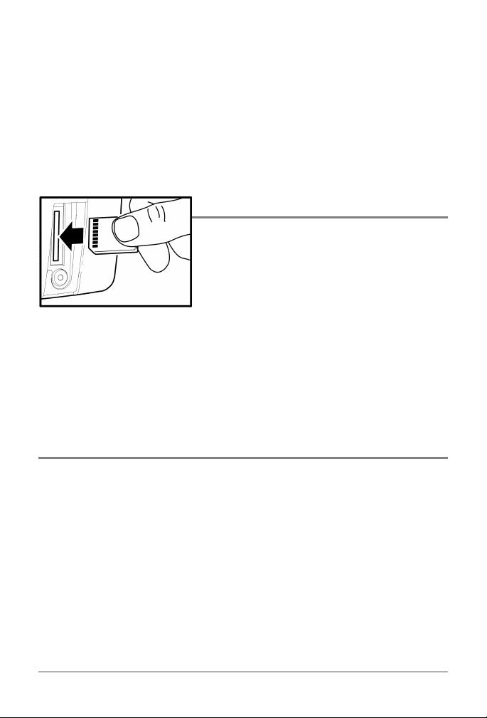
Multi-Media Card (MMC)/SD Slot
Your 700 Series™ Fishing System also has a multi-media
card (MMC)/SD slot that is used to insert optionalpurchase cards containing additional detailed maps. If
you insert an MMC/SD that contains a more detailed
chart for a particular location, your 700 Series™ Fishing
Inserting an MMC/SD
into the Card Slot
the MMC/SD should face toward the right side of the unit. Press down on the card until it
clicks into place, then replace the slot cover, making certain that the gasket is present and
positioned correctly before re-installing the cover, then replace and tighten snugly - do NOT
overtighten, as this will notimprove water resistance, and may damage the cover.
System will retrieve that chart and display it
automatically. Use the illustration to locate the position
of the MMC/SD slot cover, remove the MMC/SD slot
cover, theninsert the MMC/SDinto theslot.The labelon
Software Updates
Use the MMC/SD slot to update the software version of your control head. To update the
software in your control head, plug in the appropriate MMC/SD card that contains a software
update file; the unit will recognize it, will tell you what software version your control
head is currently running, and will ask you if you want to update the software in the unit
to match that on the MMC/SD card. You can obtain software updates from the
www.humminbird.comwebsite.
6
What’s On the Display
The 700 Series™ can display a variety of useful information about the area under and adjacent to your
Depth - water depth; can be set to alarm when the
water becomes too shallow.
Speed - if a Temp/Speed accessory or GPS Receiver
is attached, the 700 Series™ can display the speed
of the boat, and can keep a Triplog of nautical or
statute miles traveled.
Temperature - water surface temperature.
Timer - elapsed time with Temp/Speed Accessory
or GPS Receiver.
Distance - distance traveled with Temp/Speed
Accessory or GPS Receiver.
Average Speed - average speed reading with
Temp/Speed Accessory or GPS Receiver.
Bait Ball
Hard Bottom
Rocky Bottom
Second Sonar Return - when the sonar signal
bounces between the bottom and the surface of
the water and back again. Use the appearance of
the second return to determine bottom hardness.
Hard bottoms will show a strong second return,
while soft bottoms will show a very weak one or
none at all.
Cursor - available in Freeze Frame and can be
depth of a sonar return and bottom depth
Cursor Dialog Box - indicates cursor depth on
Longitude of the cursor position is shown,
be marked at the cursor position for later
NOTE: Entries in this view that list (with Temp/Speed or GPS Receiver) are available if either device is connected
receiver will be displayed on the view.
7
boat, including the following items:
positioned in the Sonar View to provide
below the cursor.
Structure - where fish may be hiding.
200 kHz, Narrow Beam Shaded Fish Symbol
83 kHz, Wide Beam Hollow Fish Symbol
Thermoclines - layers of water with different
temperatures that appear at different depths and
different times of the year. A thermocline typically
appears as a continuous band of many gray levels
moving across the display at the same depth.
Fish - fish are displayed as arches and/or fish
icons, and the unit can be set to alarm when a
fish of a certain size is detected. When a target is
detected and Fish ID+
TM
is on, a Fish ID+TMsymbol
with depth is displayed. The size of the symbol
shows the intensity of the sonar return. The unit
will clearly show schools of Bait Fish as "clouds"
of different shapes and sizes, depending on the
number of fish and boat speed.
Soft Bottom
RTS® (Real Time Sonar) Window
the display and the depth of the bottom directly below the cursor. In addition, the Latitude and
the distance to travel to the cursor position and the bearing to the cursor position. A waypoint can
retrieval and use.
to the 700 Series™ Fishing System. If both devices are connected, then only the information from the GPS
8

Views
The views available on your 700 Series™ Fishing System are:
Sonar views:
Navigation views:
• Sonar View • Bird’s Eye View
• Zoom View • Chart View
• 200/83 kHz Split Sonar View • Combo View.
• Big Digits View
• Circular Flasher View
• Screen Snapshot View
• Side Beam View
• WideSide® View.
NOTE: When you change any menu settings that affect the sonar, the view will update
immediately (i.e. you don’t have to exit the menu to apply the change to the screen). For instance,
by switching between "Inverse" and "Structure ID®" from the X-Press
alternate between the two viewing methods.
NOTE: Side Beam View and WideSide® View require the purchase of the QuadraBeamTM
transducer for the Side Beam View and the WideSide® transducer for the WideSide® View. You can
visit our website at www.humminbird.com to order these accessories online or contact our
Customer Resource Center at 1-800-633-1468.
TM
menu, it is possible to quickly
Sonar View is the default view. When the VIEW key is pressed, the display cycles through the
available views. When the EXIT key is pressed, the display cycles through the available views in
reverse order. Any view can be hidden or displayed as part of the view rotation using the Views
Menu tab.
9
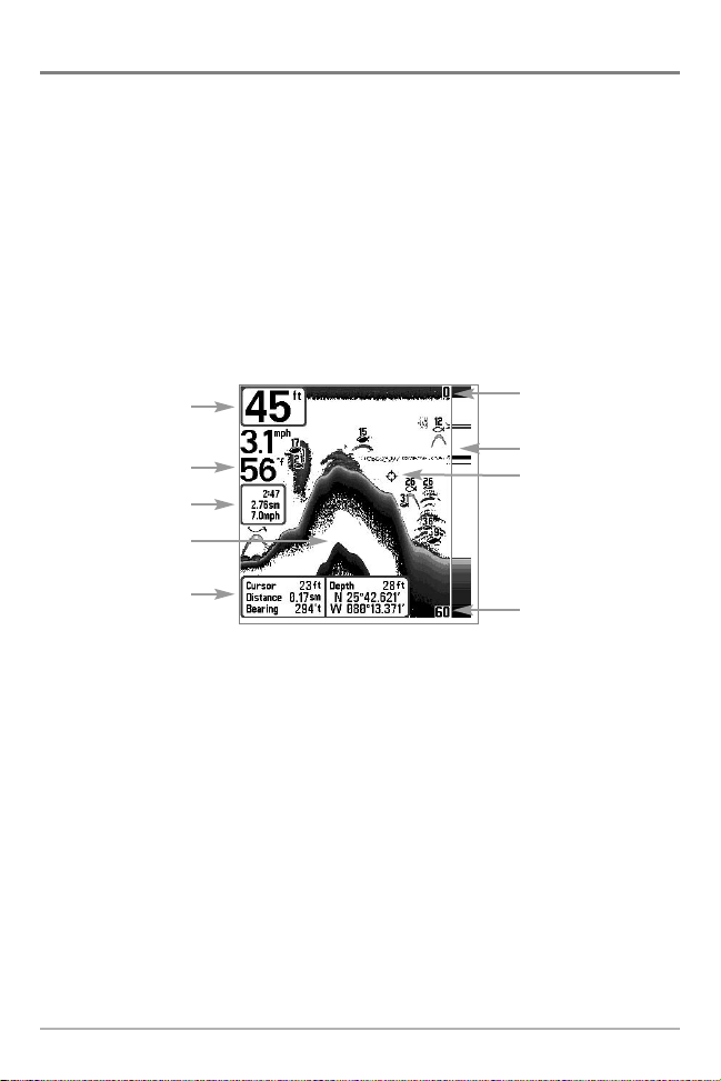
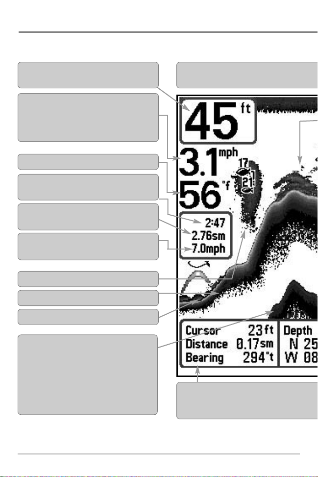
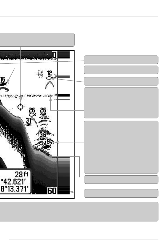
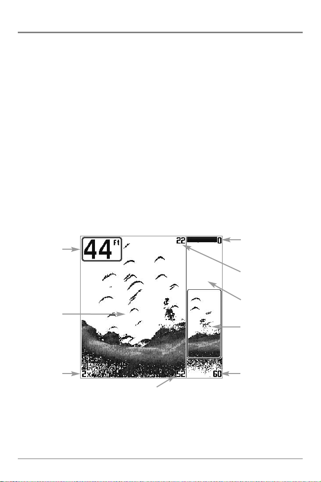
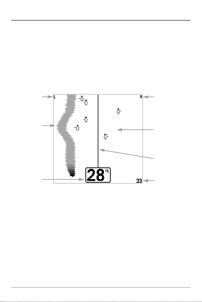
Sonar View
Sonar View presents a historical log of sonar returns. Depth is always displayed. Readouts for
temperature and speed are automatically displayed if the appropriate accessory is connected. The
most recent sonar returns are charted on the right side of the window; as new information is
received, the older information is moved across the display to the left. A Digital Depth Readout is
displayed in the upper left corner. A scale with Upper and Lower Depth Range readouts appears
along the right edge of the Sonar View. The scale indicates the distance from the surface of the
water to a depth range sufficient to show the bottom. Depth Range is automatically selected to
keep the bottom visible on the display, although you can adjust it manually as well (see Sonar
X-Press™ Menu). Six additional Digital Readouts display information from optional-purchase
accessories. These information boxes can be customized to show only the information desired
(see Setup Menu Tab, Select Readouts).
Sonar View
Depth
Temperature
Triplog
Sonar History
Window
Cursor
Dialog Box
Upper Depth
Range
RTS® Window
Cursor
Lower Depth
Range
NOTE: If the Depth number is flashing, it means that the unit is having trouble locating the bottom.
This usually happens if the water is too deep, the transducer is out of the water, the boat is moving
too fast, or for any other reason that the unit can’t accurately receive continuous data.
10
Understanding Sonar History
It is important to understand the significance of the 700 Series™
Fishing System display. The display does NOT show a literal
3-dimensional representation of what is under the water. Each
vertical band of data received by the control head and plotted on
the display represents something that was detected by a sonar
return at a particular time. As both the boat and the targets (fish)
may be moving, the returns are only showing a particular
segment of time when objects were detected, not exactly where
those objects are in relation to other objects shown on the display.
Real Time Sonar (RTS®) Window
A Real Time Sonar (RTS®) Window appears on the right side of the display in the Sonar View only.
The RTS® Window always updates at the fastest rate possible for depth conditions and shows only
the returns from the bottom, structure and fish that are within the transducer beam. The RTS®
Window plots the depth and intensity of a sonar return. (See Sonar Menu: RTS® Window) .
The Narrow RTS® Window
indicates the sonar intensity
through the use of grayscale.
The grayscale used matches
the bottom view grayscale
setting used in the sonar
history window (i.e. Inverse,
StructureID®, WhiteLine®,
Bottom Black). The depth of
the sonar return is indicated
by the vertical placement of
the return on the display
depth scale.
The Wide RTS® Window in-
dicates the sonar intensity
through the use of a bar
graph. The length of the
plotted return provides an
indication of whether the
return is weak or strong. The
depth of the sonar return is
indicated by the vertical
placement of the return on
the display depth scale. The
Wide RTS® Window does not
make use of grayscale.
11
Freeze Frame
Freeze Frame - Pressing any arrow on the 4-WAY Cursor Control key will freeze the screen and a
cursor will be displayed on the screen. The cursor can be positioned on the display using the
4-WAY Cursor Control key to determine the depth of any sonar return. The RTS® Window
continues to update in Freeze Frame. In addition, see the effects of menu setting changes with
Instant Image Update. Pressing EXIT will exit Freeze Frame and the display will start to scroll.
Freeze Frame is available in the Sonar, Sonar Zoom, and 200/83 kHz Split Sonar Views.
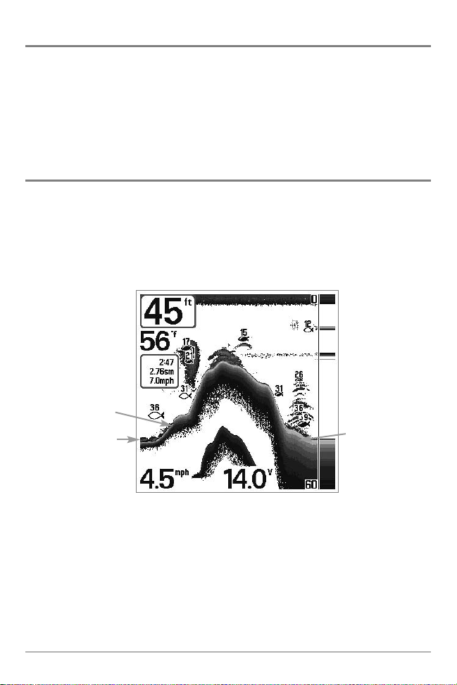
Bottom Presentation
As the boat moves, the unit charts the changes in depth on the display to create a profile of the
Bottom Contour. The type of bottom can be determined from the return charted on the display.
A Hard Bottom such as compacted sediment or flat rock appears as a thinner line across the
display. A Soft Bottom such as mud or sand appears as a thicker line across the display. Rocky
Bottoms have a broken, random appearance.
Bottom Contour Profile with RTS® Window.
Hard Bottom
Rocky Bottom
Soft Bottom
The sonar returns from the bottom, structure and fish can be represented as either Inverse
(default), WhiteLine®, Structure ID®, or Bottom Black. See Sonar X-Press™ Menu: Bottom View for
details on how to set the bottom view.
12
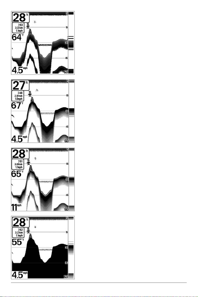
Inverse is a method where weak returns are shown with
dark pixels and strong returns with lighter pixels. This has
the benefit of ensuring that weak signals will be clearly
visible on the display.
Structure ID® represents weak returns as light pixels and
strong returns as dark pixels. This has the benefit of ensuring
that strong returns will be clearly visible on the display.
WhiteLine® highlights the strongest sonar returns in white,
resulting in a distinctive outline. This has the benefit of
clearly defining the bottom on the display.
Bottom Black displays all pixels below the bottom contour
as black, regardless of signal strength. This has the benefit of
providing a high contrast between the bottom and other
sonar returns on the display. Any targets such as fish,
structure and thermoclines will be shown using the
Structure ID® method.
13
Sonar Zoom View
Sonar Zoom View increases the displayed resolution to separate sonar returns that are very close
together, such as those caused by fish suspended close to the bottom or within structure. In Zoom
View, the display is split to show a narrow slice of the full range view on the right and the zoomed
view on the left. The full range view on the right also contains the Zoom Preview Box that shows
what part of the full range view is shown in zoom view on the left; the Zoom Preview Box tracks
the bottom in the full range view.
As the depth changes, the zoomed view updates automatically to display a magnified image of
the bottom. The Zoom Preview Box shows where the zoomed view is in relation to the full range
view. The Zoom Level, or magnification, is displayed in the lower left corner and can be changed
to suit conditions (see Sonar X-Press™ Menu: Zoom Level). Upper and Lower Zoom Depth Range
numbers indicate the depth of the water which is being viewed.
Digital depth is displayed in the upper left hand corner. The digital readouts in the Sonar Zoom
View cannot be customized; therefore, information such as water temperature and voltage are
unavailable in the Sonar Zoom View.
Sonar Zoom View
Upper Depth
Depth
Zoomed
View
Range, Full
Range View
Upper Depth
Range, Zoom View
Full Range
View
Zoom
Preview Box
Zoom Level
Lower Depth Range,
Zoom View
Lower Depth
Range, Full
Range View
14
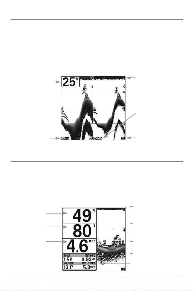
200/83 kHz Split Sonar View
Split Sonar View displays sonar returns from the 83 kHz wide beam on the left side of the screen and
displays sonar returns from the 200 kHz narrow beam on the right side of the screen. Depth is always
displayed in the upper left hand corner. You can use the Split Sonar View to make side by side
comparisons between the sonar returns from the 83 kHz wide beam and the 200 kHz narrow beam.
The digital readouts in the Split Sonar View cannot be customized; therefore, information such as
water temperature and voltage are unavailable in the Split Sonar View.
200/83 kHz Split Sonar View
Depth
83 kHz
Sonar History
Window
Upper Depth
Range
200 kHz
Sonar History
Window
Lower Depth Range
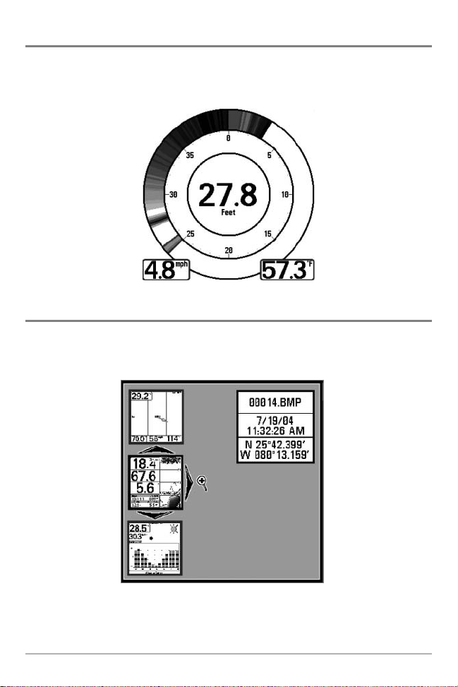
Big Digits View
Big Digits View provides digital data in a large, easy-to-see format. Depth is always displayed.
Readouts for temperature, speed and Triplog information are displayed automatically if the
appropriate accessory is connected to the 700 Series™ Fishing System. The Triplog shows distance
traveled, average speed, and time elapsed since the Triplog was last reset. The digital readouts in
the Big Digits View cannot be customized.
Big Digits View
Depth
Temperature
Speed
Timer shows the time
elapsed since Triplog
was last reset
Distance is the distance
traveled since the Triplog
was last reset
Voltage - the battery
voltage.
Average Speed shows
the speed since the
Triplog was last reset
15
Circular Flasher View
Circular Flasher View displays Real Time Sonar (RTS®) data in the traditional flasher format. Depth
and temperature are always displayed. The digital readouts in the Flasher View cannot be
customized.
Screen Snapshot View
When Screen Snapshot is enabled (from the Accessories menu tab), pressing the MARK key
creates a saved screen capture (when you have an optional-purchase MMC/SD card installed).
Screen Capture View
16

Taking a screen snapshot is a three step process: (there are four steps here??)
1. Enabling Screen Snapshot from the Accessories Menu.
2. Making a Screen Snapshot.
3. Viewing a Screen Snapshot using the Screen Snapshot View.
4. Deleting a Screen Snapshot using the Screen Snapshot X-Press™ menu.
For more information, see the Accessories Menu Tab: Using Screen Snapshot procedure and the
Screen Snapshot X-Press™ Menu.
When you start a screen snapshot, you will see a message that a waypoint has been created at
the point where your cursor is on the screen, and the screen will freeze. A status dialog box will
appear that shows the progress of the save, and that displays the numbered file name assigned
to the .BMP file that is being created, along with the percentage completed status.
The Screen Snapshot View displays up to three thumbnails of these screen captures at a time. You
can scroll through the whole list of thumbnails of screen snapshots in this view using the 4-WAY
Cursor keys. The selected thumbnail will be highlighted with arrows. See the full-sized image by
selecting a thumbnail (using the Up or Down 4-Way Cursor keys), then using the Right 4-Way
Cursor key to view the full image. A border around the full-size screen snapshot indicates that it is
just a screen snapshot, not a “live” view. You can delete the selected image, or all images, using
Delete Image or Delete All Images from the Screen Snapshot X-Press™ menu.
Side Beam View (with optional-purchase QuadraBeam™ transducer)
TM
Side Beam View is only available if you have connected a QuadraBeam
and when Transducer Select is set to QuadraBeam™ (see Sonar Menu Tab: Transducer Select). The
QuadraBeam™ transducer requires a separate purchase. This view shows sonar information from
both the left and right 90° 455 kHz beams and the 200 kHz down-looking beam in one view. The
top portion of the display presents a historical log of sonar returns from the 200 kHz downlooking sonar. The bottom portion of the display presents a historical log of sonar returns from
the 455 kHz right- and left-looking sonar. New information appears at the top, and scrolls down
the display.
transducer accessory
17
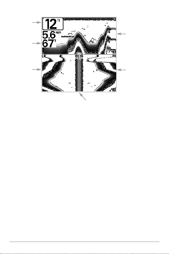
Depth
Temperature
Side Beam View
200 kHz Sonar
History Window
Left Side 455 kHz
Sonar History
Window
Water Surface Line for 455 kHz
Sonar History Windows
Right Side 455 kHz
Sonar History
Window
The sonar information from the side-looking beams reveals bottom contour, structure and fish
similar to the down-looking beam, but the area covered is to the left and right of the area shown
in the down-looking portion, so you actually see more of the bottom. The distance covered by the
right and left 90° beams is based on the depth setting for the down-looking beam, up to a
maximum of 160 feet.
18
WideSide® View (with optional-purchase WideSide® transducer)
WideSide® View is only available if you have connected a WideSide® transducer accessory
and when Transducer Select is set to WideSide® (see Sonar Menu Tab: Transducer Select). The
WideSide® transducer requires a separate purchase. The WideSide® View displays
information from the 455 kHz WideSide® transducer. Three views are available: Left, Right
and Both. The default view is Both. Information from both the left and right beams are
displayed simultaneously. The depth of the water beneath the boat is always displayed. A
bottom contour may be present while bank fishing or fishing river channels. When fishing in
the open water, a bottom contour will not be present, and only sonar returns from either
debris or fish will be displayed.
Left Side View
Bank Contour
Depth
WideSide View
Right Side View
Open Water
(no bottom
contour visible
on-screen)
Water Surface
Line
Side Beam
Depth Range
19
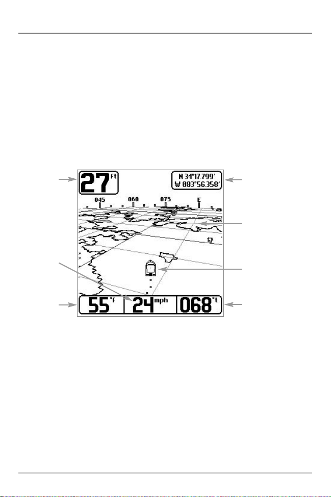
Bird’s Eye View
Bird's Eye View - This view shows a 3-D, perspective view of the track and the chart’s land contour
from a point above and behind the boat (the eye point). As the boat turns, the eye point moves to
follow the boat.
When you press the 4-WAY Cursor key in the Bird’s Eye View, the position of the eye point will
shift. This allows you to move and turn the eye point so that you can look off to the sides, or even
behind the boat. Pressing the RIGHT or LEFT arrow keys on the 4-WAY Cursor key turns the eye
point right or left, while pressing the UP arrow key moves the eye point forward, and pressing the
DOWN arrow key moves the eye point backward.
Pressing the EXIT key moves the eye point back to its original position behind and above the boat.
Bird’s Eye View
Depth
Latitude and
Longitude
Position of Boat
Land Contours
Speed of Boat
Water Surface
Temperature
Boat Icon
Bearing of Boat
with Respect to
True North
20
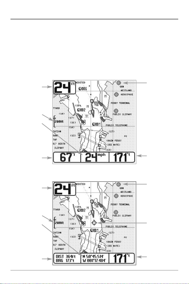
Chart View
Chart View - This view shows cartography from the built-in Uni-Map™ or an optional MMC
map for the area surrounding your current position. The current track (also known as the
position history or breadcrumb trail) showing where the boat has been, along with saved
tracks, waypoints, and the current route (when navigating), are overlaid on the chart. You can
use the 4-WAY Cursor Control key to shift/pan the chart to another area. You can use the
ZOOM (+/-) keys to zoom in and out. You can use the INFO key to get information on the chart
objects near the cursor.
Chart View without Active Cursor
Depth
Map Scale
Speed Of Boat
Water Surface
Temperature
Chart View with Active Cursor
Depth
Cartography
Bearing of Boat
with Respect to
True North
Cartography
Map Scale
Latitude and
Longitude
Position of
Cursor
Distance to
the Cursor
and Bearing
to Cursor
Active Cursor
Bearing of Boat
with Respect to
True North
21
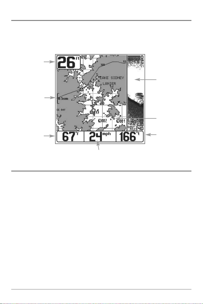
Combo View
Combo View - This view is displayed as a split screen, with Chart View on the left and Sonar View
on the right side of the screen. The width of the sonar window can be changed.
Combo View
Depth
Depth
Sonar Window
Map Scale
Cartography
Water Surface
Temperature
Speed of Boat
Bearing of Boat
with Respect to
True North
View Orientation
Both Chart and Combo views allow you to choose the orientation of the view. When North-Up
orientation is selected, True North is shown at the top of the display. In other words, objects
located to the north of the boat are drawn above the boat. When Course-Up orientation is
selected, the direction of motion of the boat is shown at the top of the display. In other words,
objects ahead of the boat are drawn above the boat. In both orientations, the view pans
automatically, so that the boat is always centered on the display. When the boat is stationary, it
is drawn as a circle. When the boat is in motion, it takes on a boat shape, pointed in the direction
of motion (always Up in the Course-Up orientation).
22
Viewing Cartography
In the Chart or Combo Views there are several cartography-related functions that you can access
using various keys.
Panning: Use the 4-WAY Cursor keys to move the chart
around on the display in the direction of the key being
pressed. When you do this, a bull's eye cursor is drawn at
the center of the screen and is linked to the boat by a gray
line, even if the boat is off the screen. At the same time, the
temperature and speed boxes in the lower left corner are
replaced with the distance and bearing from the boat to
the cursor position and the latitude/longitude coordinates
of the cursor.
Chart View with Cursor Present
display. If you zoom in beyond the available chart data, the display will go into Overzoom
mode whereby the last available chart data is amplified to reflect the scale selected. If you
zoom in so far that no cartography is available, a lat/long grid will be drawn instead.
Chart Info: Use the INFO key to get detailed information about the chart. If the cursor is active, you
will see information about the chart objects located near the cursor. If the cursor is not active, the
Chart Info menu will appear. You can select the nearest port, the nearest tide station, or the
nearest current station to see information about any of these objects.
NOTE: The built-in Uni-Map™ does not contain any Port, Tide or Current information. This information
is only available from optional-purchase MMC/SD cards.
Nearest Port: The position and services information for the nearest port to your present position
will be displayed. Press the EXIT key to remove the information box and the cursor bull’s eye will
be centered over the port position. The cursor information boxes at the bottom of the display will
indicate the distance and bearing to the port from your present position.
Nearest Tide Station: Tide information for the nearest tide station to your present position will be
displayed. This includes the position of the station and the times of the high and low tides for
today’s date. A tide graph is also displayed showing the rise and fall of the tides for the 24 hour
time period encompassing the date. You can change the date to look at tide information before
or after the date displayed by pressing the LEFT or RIGHT cursor key respectively. Press the EXIT
key to remove the information box and the cursor bull’s eye will be centered over the tide station
position. The cursor information boxes at the bottom of the display will indicate the distance and
bearing to the tide station from your present position.
Zooming: Use the Plus (+) key to Zoom In and the Minus
(-) key to Zoom Out showing the cartography at different
scales. The scale is indicated on the left side of the
23
 Loading...