

Humminbird 405SX User Manual
405SX
SINGLEBEAM
OPERATIONS MANUAL
fishfinder

THANK YOU FOR CHOOSING YOUR 405SX FISHFINDER, MADE BY
TECHSONIC INDUSTRIES, MANUFACTURER OF AMERICA’S #1 NAME IN
FISHFINDERS, HUMMINBIRD. HUMMINBIRD HAS BUILT ITS REPUTATION
BY DESIGNING AND MANUFACTURING TOP QUALITY, THOROUGHLY
RELIABLE MARINE EQUIPMENT. YOUR HUMMINBIRD PRODUCT IS
DESIGNED FOR TROUBLE-FREE USE IN EVEN THE HARSHEST MARINE
ENVIRONMENT.
IN THE UNLIKELY EVENT THAT YOUR HUMMINBIRD DOES REQUIRE
REPAIRS, WE OFFER AN EXCLUSIVE SERVICE GUARANTEE. COMPLETE
DETAILS ARE INCLUDED AT THE END OF THIS MANUAL.
WE ENCOURAGE YOU TO READ THIS OPERATIONS MANUAL CAREFULLY
IN ORDER TO GET FULL BENEFIT FROM ALL THE FEATURES AND USES OF
YOUR Humminbird PRODUCT.
WARNING! THIS DEVICE SHOULD NOT BE USED AS A
NAVIGATIONAL AID TO PREVENT COLLISION, GROUNDING,
BOAT DAMAGE, OR PERSONAL INJURY. WHEN THE BOAT IS
MOVING, WATER DEPTH MAY CHANGE TOO QUICKLY TO
ALLOW TIME FOR YOU TO REACT. ALWAYS OPERATE THE BOAT
AT VERY SLOW SPEEDS IF YOU SUSPECT SHALLOW WATER OR
SUBMERGED OBJECTS.
THANK YOU
WARNING:
Dis-assembly and repair of this electronic unit should only be performed by authorized
service personnel. Any modification of the serial number or attempt to repair the original equipment or
accessories by unauthorized individuals will void the warranty. Handling and/or opening this unit may
result in exposure to lead, in the form of solder.
WARNING: This product contains lead, a chemical known to the State of California to
cause cancer and birth defects and other reproductive harm.

Section 1: Installation preparation . . . . . . . . . . . . . . . . . . . 2
Parts Supplied . . . . . . . . . . . . . . . . . . . . . . . . . . . . . . 2
Accessories . . . . . . . . . . . . . . . . . . . . . . . . . . . . . . . . 2
Installation Overview . . . . . . . . . . . . . . . . . . . . . . . . . 2
Alternative Transducers and Mounting Methods. . . . . . 4
Beginning Installation . . . . . . . . . . . . . . . . . . . . . . . . . 5
Section 2: USING THE
405SX. . . . . . . . . . . . . . . . . . . . . . . 6
How Sonar Works . . . . . . . . . . . . . . . . . . . . . . . . . . . 6
Simulator Operation . . . . . . . . . . . . . . . . . . . . . . . . . . 6
What You See On Screen . . . . . . . . . . . . . . . . . . . 7–11
Control Functions . . . . . . . . . . . . . . . . . . . . . . . . 11–15
Menu Functions . . . . . . . . . . . . . . . . . . . . . . . . . 15–25
Section 3: ADVANCED FEATURES. . . . . . . . . . . . . . . . . . . 24
Using Diagnostic . . . . . . . . . . . . . . . . . . . . . . . . . . . 24
Section 5: MAINTENANCE/WARRANTY. . . . . . . . . . . . . . . 25
Maintenance and Troubleshooting . . . . . . . . . . . . 26–28
Warranty . . . . . . . . . . . . . . . . . . . . . . . . . . . . . . . . . 29
Service Policy . . . . . . . . . . . . . . . . . . . . . . . . . . . . . . 29
Customer Service . . . . . . . . . . . . . . . . . . . . . . . . . . . 30
Specifications . . . . . . . . . . . . . . . . . . . . . . . . . . . . . . 31
TABLE OF CONTENTS
Rev 10416E

2
INSTALLATION PREPARATION
PARTS SUPPLIED
PARTS SUPPLIED
Before installing your 405SX, please ensure the following parts are included in
the box:
• 405SX fishfinder
• Transducer with 20' of cable and mounting hardware kit
• Mounting system and mounting hardware kit
• 6' power cable
• Publications kit
Note: The 405SX includes a temperature sensor and the 405SX
+
includes speed and temperature sensors with appropriate
hardware and instructions for installation.
If any of these items is missing contact your local dealer.
ACCESSORIES
Humminbird offers a wide assortment of accessories that complement and
expand the capability of your new
405SX. These accessories are designed with
the same high standards. The Humminbird Accessory catalog included with
your unit contains descriptions of the many accessories available and ordering
information. All Humminbird accessories are available through your full-service
Humminbird dealer.
INSTALLATION OVERVIEW
The 405SX consists of two primary components to install: the control head and
the transducer.
The control head contains the sonar transmit and receive circuitry, as well as the
user controls and display. It should be installed in a location that provides access
to the controls and visibility while in use. The control head mounts on a quick
disconnect mounting system that swivels and tilts, providing flexibility for
viewing from almost anywhere on the boat.
3
INSTALLATION PREPARATION
INSTALLATION OVERVIEW
The transducer converts electrical energy from the transmitter into mechanical
pulses or sound waves. The transducer also receives the reflected sound waves
and converts them back into electrical signals for display on the control head. It
should be installed in contact with the surface of the water in an area that has
smooth water flow - usually on the transom of the boat. There are several
mounting options for the transducer. Review the
following section to determine the method that
works for you and your boat.
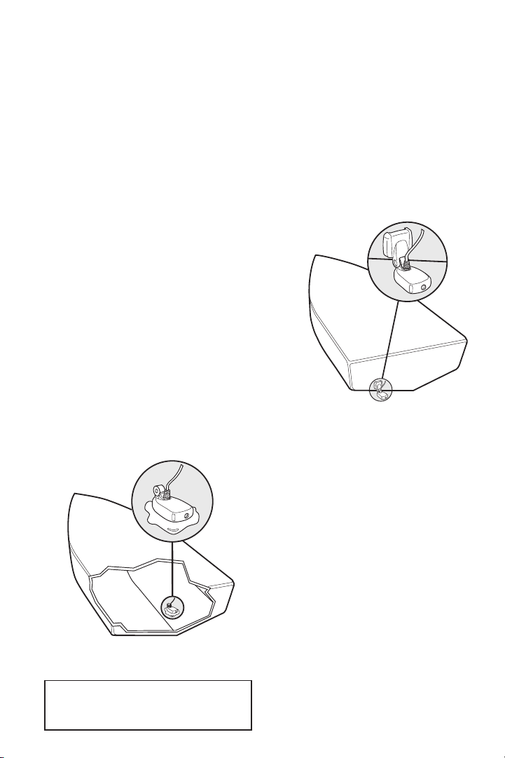
Determining How to Mount the
Transducer
The 405SX includes a model XT-6-24 transducer.
This transducer can be mounted on the transom
of the boat, or bonded to the inside of a
fiberglass hull boat.
The transom installation, which is the most
widely used, places the transducer on the outside
of the boat hull. This technique produces the
least signal loss, and provides a way to adjust the
transducer after installation. The mounting
hardware included is designed to
protect both the boat and the
transducer should the boat strike
debris in the water or when trailering.
As an alternative to transom mounting,
it is possible on many fiberglass-hulled
boats to glue the transducer on the
inside of the boat hull. Since fiberglass
has similar sonar characteristics as
water, the sonar signal can pass
through the boat hull with minimal
loss. The hull of the boat must be single
layer construction (not double-hulled).
Also, any air trapped in the lamination
of the fiberglass would prevent the
sonar signal from passing through.
Inside the Hull Mounted Transducer
Transom Mounted Transducer
For additional details reference the
TRANSDUCER INSTALLATION section of
the enclosed Installation Sheet.
4
Inside the hull installations require no holes to be drilled into the boat and
through experimentation, high-speed operation comparable to transom
mounting can be achieved. Two part, slow cure epoxy is required to glue the
transducer in place.
ALTERNATE TRANSDUCERS AND MOUNTING METHODS
The 405SX comes with everything necessary for installation and operation on
most boats. However, there are several situations which may require a different
type of transducer. Inboard boats, wood or metal hulls, and sail boats create
unique transducer mounting needs. Alternate transducers and mounting
methods are detailed below.
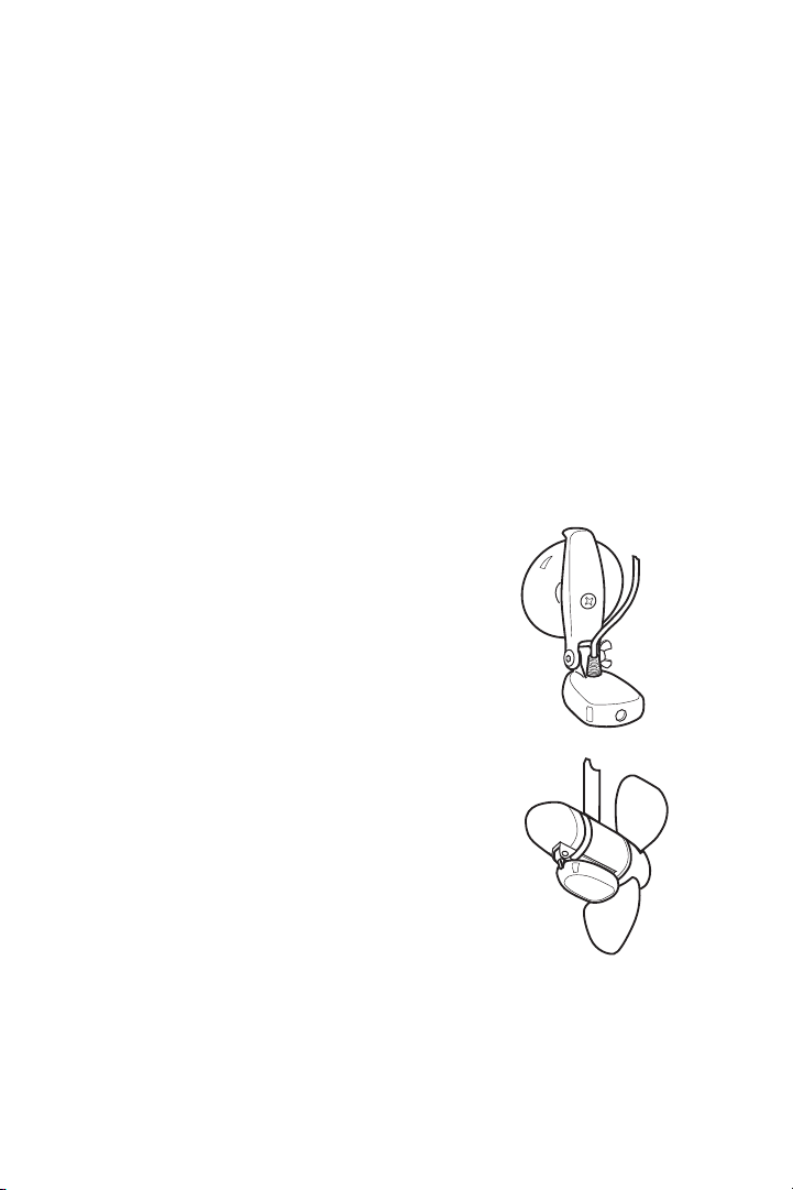
Portable Mounting
The standard transducer can be adapted for
portable installations using part number MHX-PT2.
This accessory adapts your transducer to a suction
cup mount for temporary installation on the boat
hull or other surface.
Trolling Motor Mounting
The standard transducer can also be adapted to
mount on most trolling motors using part number
AD-STM-7. This accessory includes a bracket and
hose clamp that allows mounting the transducer to
the body of most trolling motors.
TRANSDUCER EXCHANGE
Other transducers are available as replacements for
the standard transducer. You may exchange your
new and unassembled transducer for another type
by returning it to the address listed in Customer
Support. Some transducers may have additional costs. Refer to the Accessory
catalog or call Customer Support for information.
INSTALLATION PREPARATION
ALTERNATE TRANSDUCERS AND MOUNTING METHODS

BEGINNING INSTALLATION
Now that you have determined the transducer mounting method, you can
begin installation of the
405SX. The fold out installation guide included
provides detailed step by step instructions for installation of the control head
and transducer. For transom mount transducer installations, you will need the
mounting template at the back of this manual.
In addition to the parts included you need the following for installation and
operation:
• A powered hand drill and various drill bits
• Phillips and flat-head screw drivers
• A ruler or measuring tape
• Pen or pencil
• 12 volt power source (your boat’s battery)
• A 1-amp fuse
• A fuse holder (if you are wiring directly to the boat’s battery)
• Silicone sealant (for sealing drilled holes)
• 2-part, slow-cure epoxy (for inside the hull transducer installations)
INSTALLATION PREPARATION
BEGINNING INSTALLATION
5
Note: If you have purchased the 405SX+you will have in addition
to the parts and instructions above:
• Speed and Temperature sensors
• Instructions for installing speed and temperature sensors
• Appropriate hardware to mount sensors
USING THE 405SX
HOW SONAR WORKS
6
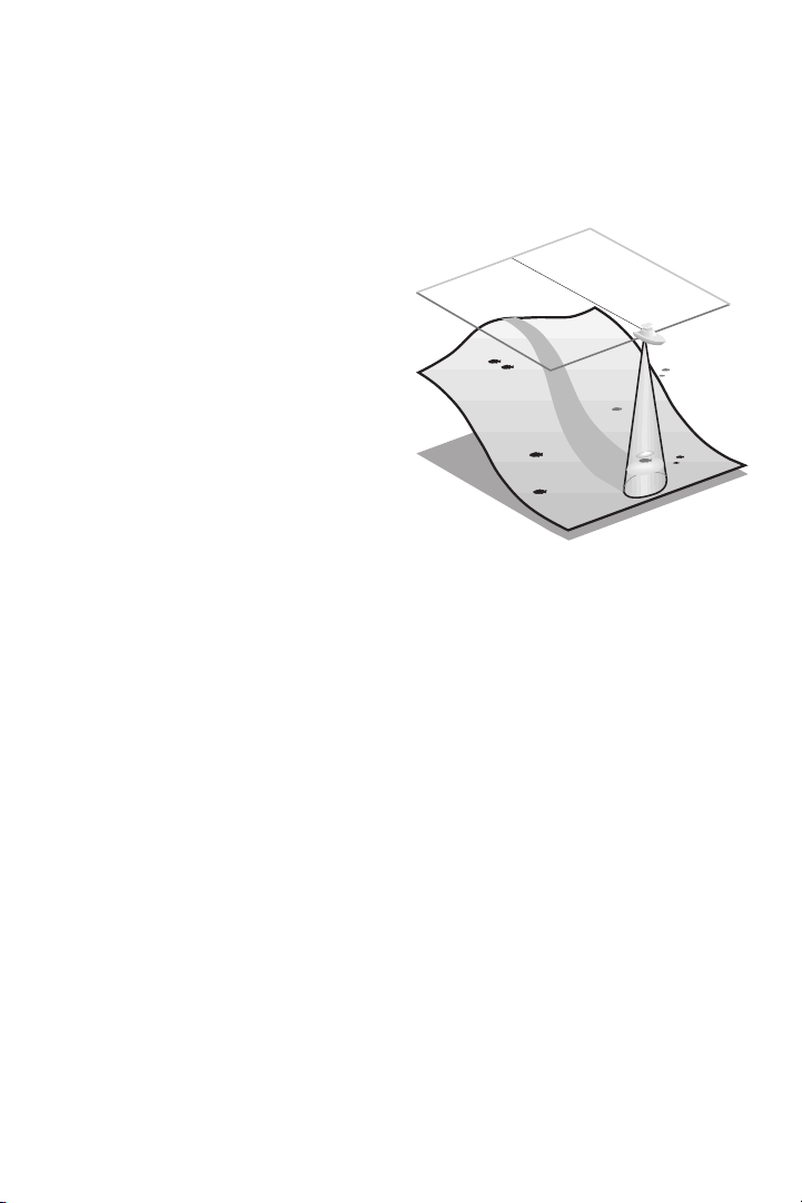
HOW SONAR WORKS
Your Humminbird unit uses sonar to
locate and define underwater objects,
define the bottom terrain, as well as
determine distance.
Sonar technology is based on sound
waves. Your Humminbird unit sends out
a sound wave signal. With this signal it
determines distance by measuring the
time between the transmission of the
sound wave and when the sound wave
is reflected off an object. Your
Humminbird uses the reflected signal to
interpret location, size and composition
of an object.
Sonar is very fast. A sound wave can travel from the surface to a depth of 600'
and back again in less than
¹⁄₄ of a second. It is unlikely that your boat can
"outrun" this sonar signal.
The
405SX is a 200 kHz, single-beam fishfinder. The 200 kHz frequency
provides excellent sonar resolution (the ability to distinguish small returns or
returns which are close to the bottom), while providing depth capabilities to
600’. The shape of the sonar beam is symmetrical and covers an area of
approximately 24 degrees side to side and front to rear.
Actual depth capability depends on factors such as bottom hardness, water
conditions, and transducer installation. Units will typically read to deeper
depths in fresh water than in salt water.
SIMULATOR OPERATION
The 405SX contains a simulator that allows you to use the unit as if you are on the
water. The simulator is invaluable for learning how to operate the
405SX.
There are two ways to start the simulator. If the unit is powered off, press and hold
the POWER button for approximately three seconds until you hear a continuous chirp.
The simulator can also be started by selecting the Simulator option on the startup screen after you power-up the unit. When this screen is shown, simply press

7
USING THE 405SX
SIMULATOR OPERATION
the DOWN ARROW until “Simulator” is
highlighted. When the screen times out, the
unit will be in simulator mode.
When in simulator operation, the
405SX
responds to control inputs as if it is in actual
operation, so feel free to experiment, or to
customize the unit for your particular
operation.
To exit Simulator mode, power the unit off.
FEATURE MEMORY
If your 405SX is installed with a transducer connected, any changes you make
to the set-up or User Options (see Control Functions) while in Simulator are
retained in the unit’s memory. This allows you to use simulator to experiment
with the various set-up options, and retain your selected settings for normal
operation.
If you are using the
405SX in Simulator when no transducer is connected, any
selected options are lost when the unit is powered off. The
405SX will return
to Factory Settings, or options selected when last used with a transducer, if no
transducer is connected.
IMPORTANT: A transducer must be connected to the 405SX in
order to retain user settings selected when in simulator mode. If
no transducer is detected, the unit defaults to pre-selected
options when powered off.
What You See On-Screen
Your 405SX uses a 160 x 160 matrix FSTN LCD display. This display provides
outstanding viewability in all light conditions over a wide range of
temperatures.
At initial power-up, the
405SX uses settings that were set at the factory. After
initial use, the
405SX will remember the settings you enter.
There are several elements on-screen that are common to all modes of operation.
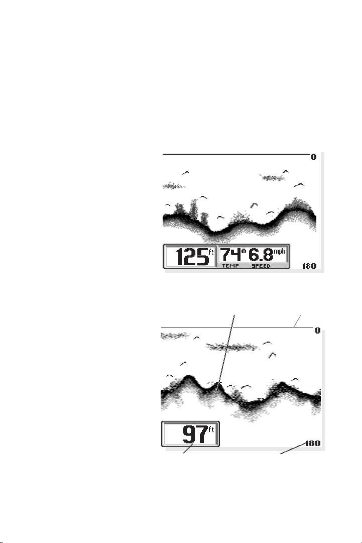
Temperature/Speed. The initial screen layout takes one of two basic forms
depending on whether the optional Temp/Speed accessory is installed. Figure
A shows the default view when the Temp/Speed accessory is installed. Figure B
shows the default view when the Temp/Speed accessory is not installed.
Depth. The digital depth
number shows the water depth
directly beneath the transducer
location.
Depth Range. The depth range
is shown to the right of the screen.
The upper number is 0 indicating
the surface of the water. The lower
number is one of the nine depth
ranges available that best match the
depth of the water. As the depth of
the water changes, the range
changes as necessary in order to
retain a bottom representation onscreen. When in Auto mode,
the horizontal line at the top
of the screen is the “zero
line,” representing the surface
of the water. Occasionally
there is a gap in this line. This
gap indicates the unit is updating the display even if the
bottom is not visible onscreen, or if the bottom
information is not changing.
New sonar information appears
on the right side of the graphic
area of the display and moves
to the left as new information
is displayed. The
405SX
automatically selects the
appropriate depth range to show the depth of water beneath the transducer.
8
Bottom Depiction
USING THE 405SX
WHAT YOU SEE ON-SCREEN
Figure B
Zero Line
Figure A
Water Depth
Depth Range
This range is selected so the bottom representation is typically shown about ²⁄₃
down the display.
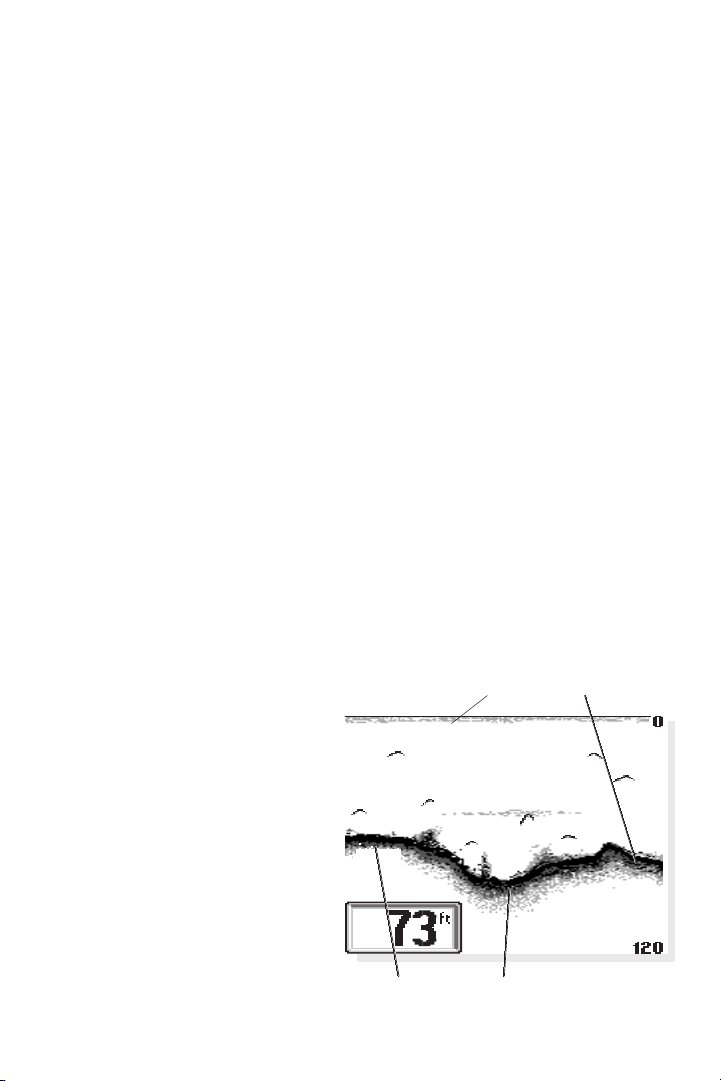
Bottom. The graphic depiction of the bottom provides the user with an
effective tool for understanding the composition of the bottom. The FSTN type
display uses 4 discrete levels of gray to indicate the intensity of the returned
sonar signal. The
405SX can display even the smallest sonar returns with light
gray pixels. Larger returns are displayed with darker shades of gray. If the
bottom is hard and smooth, the bottom depiction is narrow and dense. If the
bottom is soft mud or sand, the depiction will be thick and less dense. This
indicates that much of the signal is absorbed by the soft bottom. If the bottom
is rocky or rugged in composition, the depiction is of varying density and
textured in appearance.
Wave action also affects the bottom depiction. The information drawn is a
distance measurement, so if the boat is moving up and down over flat bottom,
the bottom depiction often appears in regular variations that match wave
timing.
Structure. Structure is defined as any object physically attached to the bottom.
The sonar configuration of the
405SX is optimized to give the most accurate
depiction of bottom structure possible. Grass, trees, stumps, wrecks or other
debris are accurately displayed, however the depiction of these objects varies
with boat speed and direction. The
best way to learn to interpret
structure is to operate the
405SX
over a variety of known conditions
and experiment with user functions
to best represent those conditions
on-screen.
Surface Clutter. Surface clutter is
the layer of water near the surface
that is rich in algae and other
growth, and often is aerated by
wind or wave action. This area of
water interferes with sonar
transmission and often appears onscreen as regular clusters of individual dots near the “0” line.
9
USING THE 405SX
WHAT YOU SEE ON-SCREEN
Surface Clutter Rocky Bottom
Hard Bottom Soft Bottom
 Loading...