


SmartAX MT882 ADSL Router
User Manual
HUAWEI TECHNOLOGIES CO., LTD.

SmartAX MT882 ADSL Router User Manual
Issue 01
Date 2007-09-06
No. 103074
Huawei Technologies Co., Ltd.
Address: Huawei Industrial Base
Bantian, Longgang
Shenzhen 518129
People's Republic of China
Website: http://www.huawei.com
Email: terminal@huawei.com
Copyright © Huawei Technologies Co., Ltd. 2007. All rights reserved.
No part of this document may be reproduced or transmitted in any form or by
any means without prior written consent of Huawei Technologies Co., Ltd.
Trademarks and Permissions
and other Huawei trademarks are trademarks of Huawei Technologies
Co., Ltd.
All other trademarks and trade names mentioned in this document are the
property of their respective holders.
Notice
The information in this document is subject to change without notice. Every
effort has been made in the preparation of this document to ensure accuracy
of the contents, but all statements, information, and recommendations in this
document do not constitute the warranty of any kind, express or implied.

Federal Communications Commis sion (FCC ) S t a teme nt
This device complies with part 15 of the FCC Rules. Operation is subject to the
following two conditions: (1) This device may not cause harmful interference,
and (2) this device must accept any interference received, including
interference that may cause undesired operation.
Safety Precautions
General Requirements:
z Before you install and use the device, read these safety precautions
carefully and observe them during operation.
z During storage, transportation and operation of the device, keep the
device dry.
z During storage, transportation and operation of the device, avoid
collision and crash of the device.
z Never attempt to dismantle the device by yourself. In case of any
fault, contact the appointed maintenance center for repair.
z Without prior written consent, no organization or individual is
permitted to make any change to the structure or safety design of
the device. Huawei Technologies Co., Ltd. is not liable to any
consequences or legal issues due to such changes.
z While using the device, observe all applicable la ws, directives and
regulations, and respect the legal rights of other people.
Environmental Requirements:
Place the device at a well-ventilated place. Do not dispose the
z
device to direct sunlight.
Keep the device clean and free of dusts.
z
Place the device on a stable platform.
z
Do not place any object on top of the device. Otherwise, the device
z
may be too hot during operation. It can even be deformed or
damaged by the heavy load.
Keep at least 10 cm between the device and the closest object for
z
heat dissipation.
Do not place the device on or near any object that can easily catch
z
fire, such as something made of rubber.

Keep the device far away from any heat source or bare fire, such as
z
a candle or an electric heater.
Keep the device far away from any household appliance with strong
z
magnetic field or electromagnetic field, such as a microwave oven
or a refrigerator.
Operating Requirements:
Do no let a child operate the device without guidance.
z
Do not let a child play with the device or any accessory. Swallowing
z
the accessories may lead to peril.
Use the accessories provided or authorized by the manufacturer
z
only.
The power supply of the device shall meet the requirements of the
z
input voltage of the device.
Before plugging or unplugging any cable, shut down the device and
z
disconnect it from the power supply.
While plugging or unplugging any cable, make sure that your hands
z
are completely dry.
Do not tread on, pull or over-bend any cable. Otherwise, the cable
z
may be damaged, leading to malfunction of the device.
Do not use an old or a damaged power cable.
z
During lightning weather, stop using the device and disconnect it
z
from the power supply. Unplug the power plug and the ADSL twisted
pair, to avoid lightning strike.
If the device is not used for a long time, disconnect it from the power
z
supply and unplug the power plug.
In any of the following cases, stop using the device, disconnect it
z
from the power supply and unplug the power plug immediately:
there is smoke emitted from the device, or there is some abnormal
noise or smell. Contact the specified maintenance center for repair.
Avoid any object (such as metal shavings) from entering the device
z
from the heat dissipation intakes.
Do not scratch or abrade the shell of the device. This may lead to
z
malfunctions of the device. The shed painting material may also
lead to skin allergy.

Keep the power plug clean and dry. Using a dirty or wet power plug
z
may lead to electric shock or other perils.

文档名称 文档密级
Note: This equipment has been tested and found to comply with the limits for a Class B
digital device, pursuant to part 15 of the
FCC Rules. These limits are designed to provide reasonable protection against harmful
interference in a residential installation.
This equipment generates, uses and can radiate radio frequency energy and, if not
installed and used in accordance with the
instructions, may cause harmful interference to radio communications. However, there is
no guarantee that interference will not
occur in a particular installation. If this equipment does cause harmful interference to radio
or television reception, which can be
determined by turning the equipment off and on, the user is encouraged to try to correct
the interference by one or more of the
following measures:
—Reorient or relocate the receiving antenna.
—Increase the separation between the equipment and receiver.
—Connect the equipment into an outlet on a circuit different from that to which the
receiver is connected.
—Consult the dealer or an experienced radio/TV technician for help.
2007-9-24
华为机密,未经许可不得扩散 第 1 页, 共 1 页

Table of Contents
Chapter 1 Introduction .....................................................................1
1.1 Functions and Features.........................................................1
1.2 Appearance ...........................................................................1
1.2.1 Front Panel .................................................................2
1.2.2 Rear Panel..................................................................4
Chapter 2 Installation of the MT882 ................................................6
2.1 Preparation............................................................................6
2.2 Connecting the MT882 ..........................................................6
2.3 Installing the USB Driver .......................................................8
2.3.1 Installing the USB Driver in Linux ...............................8
2.3.2 Installing the USB Driver in MAC OS X ....................11
2.3.3 Installing the USB Driver in Windows Vista/XP/2K...15
2.4 Setting Up the Configuration Environment..........................19
2.4.1 Planning the Parameters ..........................................19
2.4.2 Operation ..................................................................20
2.5 Web Setup Page .................................................................21
Chapter 3 Service Configuration...................................................23
3.1 Configuration Method..........................................................23
3.1.1 Protocol Model..........................................................23
3.1.2 Steps.........................................................................24
3.2 Service Modes of the MT882 ..............................................25
3.3 Configuring the Pure Bridge Mode......................................27
3.3.1 Preparation ...............................................................27
i

3.3.2 Steps.........................................................................28
3.4 Configuring the PPPoE Mode .............................................29
3.4.1 Preparation ...............................................................30
3.4.2 Steps.........................................................................31
3.5 Configuring the PPPoA Mode .............................................33
3.6 Configuring the RFC2684B Mode .......................................33
3.6.1 Preparation ...............................................................34
3.6.2 Steps.........................................................................34
3.7 Configuring the RFC2684(IPoA) Mode ...............................37
Chapter 4 Other Configurations ....................................................38
4.1 Changing the LAN IP Address ............................................38
4.2 Changing the Administrator Password................................39
4.3 Restoring the Default Settings ............................................39
4.4 Firmware Upgrade...............................................................40
Chapter 5 Troubleshooting............................................................41
5.1 Fixing Common Problems...................................................41
5.2 FAQs ...................................................................................42
Chapter 6 Technical Specifications ..............................................44
Chapter 7 Appendix ........................................................................46
7.1 Default Settings ...................................................................46
7.1.1 Common Default Parameters ...................................46
7.1.2 Default PVC Parameters ..........................................46
7.2 Acronyms and Abbreviations ..............................................48
ii

Chapter 1 Introduction
This chapter describes the functions and the appearance of the
SmartAX MT882 ADSL Router (hereinafter referred to as the MT882).
1.1 Functions and Features
The MT882 is a type of Asymmetric Digital Subscriber Line (ADSL)
terminal. Using the MT882 and a telephone line, you can enjoy data,
video and audio services at a high speed.
The features of the MT882 are:
z High transmission rate: The maximum downlink transmission
rate is 24 Mbit/s. The maximum uplink transmission rate is 1.2
Mbit/s.
z Strong network adaptability: The MT882 can interconnect
with multiple Digital Subscriber Line Access Multiplexers
(DSLAMs).
z Strong maintainability: The MT882 provides a number of
indicators, helping you to locate failures.
z Easy operation: The MT882 provides user-friendly interfaces
for configuration and management.
1.2 Appearance
This section describes the appearance of the MT882.
1

1.2.1 Front Panel
Figure 1-1 shows the front panel of the MT882.
Figure 1-1 Front panel of the MT882
Note:
The figure of the front panel is only for your reference.
Table 1-1 describes the indicators on the front panel.
Table 1-1 Indicators on the front panel
Indicator Status Description
Power
Steady
green light
The MT882 is powered on.
Off The MT882 is powered off.
2

Indicator Status Description
ADSL
LINK
ADSL
ACT
LAN
Blinking
green light
The MT882 is being activated.
On The MT882 is activated.
Blinking
orange
The built-in PPP dial-up software is dialing.
light
Steady
orange
light
Off
Blinking
green light
Off
The built-in PPP dial-up software
completes dialing successfully.
The telephone line is not connected or the
MT882 is preparing for the next activation.
Data is being transmitted over the ADSL
interface.
No data is transmitted over the ADSL
interface.
On The Ethernet interface is connected.
Blinking
green light
Blinking
orange
light
Data is being transmitted over the Ethernet
interface and the data rate is 10 Mbit/s.
Data is being transmitted over the Ethernet
interface and the data rate is 100 Mbit/s.
Off The Ethernet interface is not connected.
3

Indicator Status Description
USB
Steady
green light
Blinking
green light
The USB interface is connected.
Data is being transmitted over the USB
interface.
Off The USB interface is not connected.
Note:
If the MT882 fails to activate, it tries again after one minute. The ADSL
LINK indicator is off during this period.
1.2.2 Rear Panel
Figure 1-2 shows the rear panel of the MT882.
Figure 1-2 Rear panel of the MT882
4
Note:
The figure of the rear panel is only for your reference.
Table 1-2 describes the interfaces and buttons on the rear panel.
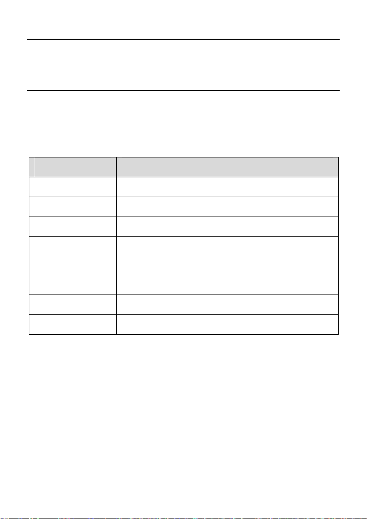
Table 1-2 Interfaces and buttons on the rear panel
Interface/Button Description
ADSL It connects with the Modem interface of a splitter.
USB It connects with a computer.
Ethernet It connects with a computer or a switch.
It restores the default settings of the MT882.
Reset
Once you press this button, all your customized
settings will be lost. Be cautious with this
operation.
Power It powers on or off the MT882.
12V AC 0.8A It connects with the power adapter.
5

Chapter 2 Installation of the MT882
This chapter introduces the installation of the MT882.
2.1 Preparation
Before installing the MT882, prepare the following components:
z Ethernet card: The MT882 communicates with a computer
through an Ethernet card. Make sure that an Ethernet card is
installed on the computer before connecting the MT882 with
the computer.
z Splitter (optional): A splitter can separate the data signals
from the voice signals being transmitted over a telephone line.
Only with this component can you make a telephone call and
access the Internet at the same time.
2.2 Connecting the MT882
You can connect the MT882 according to Figure 2-1.
6
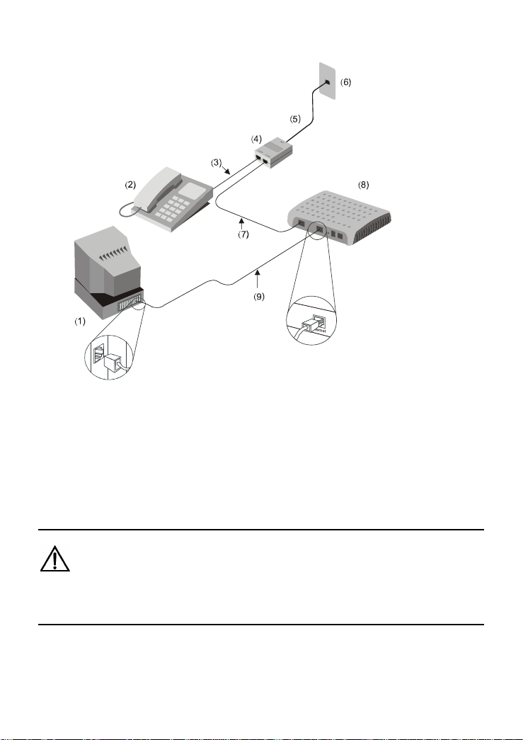
Figure 2-1 Connecting the MT882
(1) PC (2) Phone (3) RJ-11 telephone line
(4) Splitter (5) RJ-11 telephone line (6) Phone jack
(7) RJ-11 telephone
line
(8) MT882 (9) RJ-45 Ethernet cable
Caution:
Before connecting the MT882, power off the MT882 and the computer.
7

Operation:
1) Connect the interfaces of the splitter with other devices by
using a telephone line:
z LINE interface --> telephone jack on the wall
z MODEM interface --> ADSL interface of the MT882
z PHONE interface --> telephone
2) Connect the Ethernet interface of the MT882 with the
Ethernet interface of the computer by using a straight through
cable.
3) Connect the MT882 to a power socket by using the provided
power adapter.
4) Press the Power button of the MT882 to power on the
MT882.
5) Check the Power indicator on the front panel of the MT882.
If it is on, the MT882 is powered on.
2.3 Installing the USB Driver
You need to install the USB driver on your PC before using the
USB connection. The installation process of the USB driver varies on
different systems. The following provides instructions for three systems:
Linux, MAC OS 9/10, and Windows.
2.3.1
Installing the USB Driver in Linux
To install the USB driver in a Linux system, do as follows.
1) Start RedHat 8.0, and log in as root.
2) Copy the original codes to the usb_driver_for_linux
directory.
8

3) Execute the following commands:
# cd usb_driver_for_linux
# make
# make install
Note:
usb_driver_for_linux is the file name where you store the driver.
4) Edit file located on /etc/rc.d/rc.local, append two lines as
below:
insmod /usr/local/lib/trendchip/trendchip.o &>/dev/null &
ifconfig eth1 192.168.1.2 up &>/dev/null &
Note:
This step will make trendchip's driver be loaded automatically when
system startup.
5) Create a new file named ifcfg-eth1 in
/etc/sysconfig/networking/device/. We assume that you
already have an interface eth0. Add the following content in
the file.
USERCTL=no
9

PEERDNS=yes
GATEWAY=192.168.1.1
TYPE=Ethernet
DEVICE=eth1
HWADDR=00:aa:bb:cc:00:01
BOOTPROTO=none
NETMASK=255.255.255.0
ONBOOT=no
IPADDR=192.168.1.2
NETWORK=192.168.1.0
BROADCAST=192.168.1.255
Note:
This step will create a new Ethernet interface eth1 and configure this
properties.
6) Create or modify the file named resolv.conf in
/etc/sysconfig/networking/profiles/default/. Add the
following content:
nameserver <ip of your primary DNS>
nameserver <ip of your second DNS>
10

Note:
This step is configuring your DNS setting. Note that <ip of your * DNS>
is the actual IP address of the DNS which you should get from your ISP.
7) Create a new file named ifcfg-eth1 in
/etc/sysconfig/network-scripts/. Add the following content:
DEVICE=eth1
BOOTPROTO=none
BROADCAST=192.168.1.255
IPADDR=192.168.1.2
NETMASK=255.255.255.0
NETWORK=192.168.1.0
ONBOOT=no
USERCTL=no
PEERDNS=no
GATEWAY=192.168.1.1
TYPE=Ethernet
8) Reboot PC and then plug and power on your ADSL modem.
2.3.2 Installing the USB Driver in MAC OS X
To install the MT882 USB Driver on a MAC OS X system, do as
follows.
11

1) Run the MAC USB driver from the CD-ROM provided with
MT882, and decompress it.
2) Double-click the Installer to start the installation.
3) Click Next to display the Authenticate page.
12

4) Enter the name and password of the administrator, and click
OK.
5) Read the information carefully and click Accept.
13

6) Select a destination folder to install and click Next.
7) Select Restart now and click Finish to restart your
computer.
14

2.3.3 Installing the USB Driver in Windows Vista/XP/2K
To install the USB driver on a Windows system, do as follows.
1) Connect the MT882 with your computer by using an USB
cable.
2) Power on the MT882.
3) Double-click Setup.exe on the CD-ROM provided with
MT882 to display the Setup Wizard window, and you will
see the Hello page.
4) Click Next to continue the installation.
15

5) Select Typical and Click Next.
16

6) Click Next to continue the installation.
17

7) Click Continue Anyway to continue the installation.
18

8) Click Finish.
2.4 Setting Up the Configuration Environment
You can configure the MT882 through the Web setup page. This
chapter describes how to set up the configuration environment of the
MT882.
2.4.1 Planning the Parameters
Before setting up the configuration environment, plan the following
parameters.
19

Table 2-1 Parameters for the configuration environment
Item Description
Username and password
of the administrator of the
MT882
LAN IP address and
subnet mask of the
MT882
Default:
z Username: admin
z Password: admin
Default:
z IP address: 192.168.1.1
z Subnet mask: 255.255.255.0
Make sure that the IP address of the
computer is in the same network
segment as the LAN IP address of the
IP address and subnet
mask of the computer
MT882.
For example:
z IP address: 192.168.1.100
z Subnet mask: 255.255.255.0
2.4.2 Operation
Follow these steps to set up the configuration environment.
Step To... Do...
1
Connect the
MT882
For details, see section
MT882
."
2.2 "Connecting the
20

Step To... Do...
Taking Internet Explorer 6.0 as an example:
1) Launch the Internet Explorer.
2) Choose Tools > Internet Options... to
display the Internet Options dialog
box.
3) Choose the Connections tab and click
LAN Settings....
4) Deselect the Use a proxy server for
your LAN (These settings will not
apply to dial-up or VPN
connections) checkbox.
1) In the address bar of the Internet
Explorer, enter http://192.168.1.1 (the
default IP address of the MT882).
2) Press Enter to display the login page.
3) Enter the username and the password
of the administrator.
Then you can access the Web setup page.
2
3
Check and
ensure that
the proxy
server is not
used
Log in to the
Web setup
page
Note:
The computer must be set according to the parameters of the MT882.
For details, see
Chapter 3 "Service Configuration."
2.5 Web Setup Page
The Web setup page of the MT882 can be divided into two parts:
21

z The navigation tree: On the left of the page, it allows you to
access different setup pages.
z Configuration area: On the right of the page, it displays the
configuration data.
22

Chapter 3 Service Configuration
This chapter introduces how to configure the MT882.
Note:
The figures in the following configuration operations are only for your
reference.
3.1 Configuration Method
3.1.1 Protocol Model
Figure 3-1 shows the protocol model for the connection between
the MT882 and the DSLAM at the office end.
PVC
ATM
(3)
MACATM
PHYADSL
MAC
PHY
(1)
PHY ADSL
(2)
Figure 3-1 Protocol model
(1) PC (2) MT882 (3) DSLAM
23

The data between the MT882 and the DSLAM are transmitted in
the Asynchronous Transfer Mode (ATM). To configure the MT882 for
different services, you need to configure the Permanent Virtual
Channel (PVC) and other parameters.
3.1.2
Steps
The steps to configure the service modes are as follows.
Step To... Do...
Establish the
1
2
3
Note:
DHCP = Dynamic Host Configuration Protocol
configuration
environment
Configure the
MT882
Configure
your computer
See section
Configuration Environment
1) Choose the PVC to be configured.
2) Choose the service mode of the PVC
and configure the parameters of the
PVC.
3) Configure other options, such as the
DHCP function.
4) Save the configuration and reboot the
MT882.
Configure the parameters of the Ethernet
card on your computer according to the
service mode of the MT882. Alternatively,
install the dial-up software in the computer.
2.4 "Setting Up the
."
24

3.2 Service Modes of the MT882
The MT882 supports multiple service modes. To choose a proper
service mode, you need to take the DSLAM settings into consideration.
Table 3-1 lists the available service modes.
Table 3-1 Service modes of the MT882
Service Mode Working Method Configuration
Bridge
PPPoE
PPPoA
z Take the MT882 as bridge
equipment.
z Use the PPP dial-up
software of the computer to
dial a number.
z Take the MT882 as a router.
z Use the built-in PPP dial-up
software of the MT882 to dial
a number.
z Use the PPPoE
Refer to
"Configuring the
Pure Bridge
Mode
Refer to
"Configuring the
PPPoE Mode
encapsulation mode to
encapsulate the packets.
z Take the MT882 as a router.
z Use the PPP dial-up
software of the MT882 to dial
a number.
z Use the PPPoA
Refer to
"Configuring the
PPPoA Mode
encapsulation mode to
encapsulate the packets.
3.3
".
3.4
".
3.5
".
25

Service Mode Working Method Configuration
z Take the MT882 as a router.
z The MT882 obtains an IP
3.6
".
RFC2684B
address from DHCP server
or uses the static public IP to
access the Internet.
z Use the RFC2684B
Refer to
"Configuring the
RFC2684B
Mode
encapsulation mode to
encapsulate the packets.
z Take the MT882 as a router.
RFC2684(IPoA)
z The MT882 uses the static
public IP address to access
the Internet.
z Use the IPoA encapsulation
mode to encapsulate the
Refer to
3.7
"Configuring the
RFC2684(IPoA)
".
Mode
packets.
Note:
ISP = Internet Service Provider
PPPoE = PPP over Ethernet
PPPoA = PPP over ATM
IPoA = Internet Protocol over ATM
Caution:
Some settings are validated only after the MT882 is rebooted. Follow
the instructions in the configuration page.
26

3.3 Configuring the Pure Bridge Mode
In the pure bridge mode, the MT882 functions as a bridge. You
need to install the PPP dial-up software in your computer to access the
Internet.
This section describes how to configure the MT882 to work in the
pure bridge mode. It also describes how to configure your computer to
access the network through the MT882.
3.3.1
Preparation
Table 3-2 lists the configuration items.
Table 3-2 Configuration items for the pure bridge mode
Item Configuration
PVC Mode Bridge
Active Yes
VPI/VCI Provided by the ISP
Encapsulation RFC2684
Install the PPP dial-up software to your
PPP dial-up software
Username and password
for the PPPoE dial-up
computer to access the Internet (The
Windows XP operation system is
provided with the PPP dial-up software)
Provided by the ISP
27

3.3.2
Steps
You need to configure the MT882 and your computer in turn.
I.
Configuring the MT882
The steps are as follows:
1) Log in to the Web setup page of the MT882. For details, see
section
2) Choose Basic > WAN Setting in the navigation tree to
display the WAN configuration page.
3) Select the PVC, which needs configuring, from the PVC
drop-down menu of the WAN configuration page.
4) Select Bridge from the Mode drop-down menu. Set the
Active to Yes. Configure relevant parameters in
according to the values in the
5) Click Submit.
6) Select Tools > Reboot in the navigation tree.
7) Select Current Settings in the Reboot page. Click Restart
to save the configuration.
2.4 "Setting Up the Configuration Environment."
Figure 3-2
Table 3-2.
Figure 3-2 Configuring the pure bridge mode
28

II. Configuring Your Computer
After configuring the MT882, install the PPP dial-up software in
your computer to access the network.
The Windows XP (Professional) operating system has built-in
PPPoE dial-up software. Take the Windows XP system as an example,
the steps to set up a PPP dial-up connection are as follows:
1) Choose Start > All Programs > Accessories >
Communications > Network Connections.
2) Click Create a new connection in the displayed page.
3) Click Next in the New Connection Wizard dialog box.
4) Choose Connect to the Internet and click Next.
5) Choose Set up my connection manually and click Next.
6) Choose Connect using a broadband connection that
requires a username and password and click Next.
7) Enter the name of the connection you are creating. Then click
Next.
8) Choose Anyone's use or My use only and click Next.
9) Enter the username and password. Then click Next.
10) Click Finish.
3.4 Configuring the PPPoE Mode
In the PPPoE mode, the MT882 uses the built-in PPP dial-up
software for dialing. The MT882 functions as a router to connect your
computer to the network.
29

This chapter describes how to configure the MT882 to work in the
PPPoE mode. It also describes how to configure your computer to
access the network through the MT882.
3.4.1
Preparation
Table 3-3 lists the configuration items.
Table 3-3 Configuration items for the PPPoE mode
Item Configuration
PVC mode Routing
Active Yes
Default route Enable
NAT Enable
VPI/VCI Provided by the ISP
Encapsulation PPPoE
Username and password for
the PPPoE dial-up
Service Name Specified by users
RIP Disabled
DHCP mode of the MT882 Enable the DHCP server
Provided by the ISP
30

Note:
After the DHCP server is enabled, the MT882 can assign a private IP
address to the computer.
3.4.2
Steps
I.
Configuring the MT882
The steps are as follows:
1) Log in to the Web setup page. For details, see section
2.4 "Setting Up the Configuration Environment."
2) Choose Basic > WAN Setting in the navigation tree to
display the WAN configuration page.
3) Choose the PVC to be configured and click the editing icon.
4) Select Routing in the PVC Mode field.
5) Select PPPoE from the Encapsulation drop-down menu.
Set the Active to Yes. Configure relevant parameters in
Figure 3-3 according to the values in the Table 3-3.
31

Figure 3-3 Configuring the PPPoE mode
32

6) Click Submit.
7) Choose Basic > DHCP in the navigation tree to display the
DHCP configuration page.
8) Choose DHCP Server and click Submit.
9) Choose Tools > Reboot in the navigation tree.
10) Select Current Settings in the Reboot page. Click Restart
to save the configuration.
II.
Configuring Your Computer
Configure the Ethernet card on your computer, so that your
computer can automatically obtain such information as the IP address,
gateway and Domain Name Server (DNS).
3.5 Configuring the PPPoA Mode
In the PPPoA mode, the MT882 uses the built-in PPP dial-up
software for dialing.
It is similar to configure the PPPoA mode as to configure the
PPPoE mode. The differences are: if configure the PPPoA, select
PPPoA from the Encapsulation drop-down menu; if configure the
PPPoE, select PPPoE from the Encapsulation drop-down menu. For
details, refer to
3.4 "Configuring the PPPoE Mode".
3.6 Configuring the RFC2684B Mode
This section mainly introduces how to configure the MT882 in the
RFC2684B mode and how to configure your computer to access the
network through the MT882.
33

3.6.1 Preparation
Table 3-4 shows the configuration preparation.
Table 3-4 Configuration for the RFC2684B mode
Name Configuration
PVC mode Routing
Active Yes
Default route Enable
NAT Enable
VPI/VCI Provided by the ISP
Encapsulation RFC2684B
IP address/subnet
mask
IP address of the
gateway
RIP Disabled
DHCP mode of the
MT882
3.6.2
Steps
I.
Configuring the MT882
The steps are as follows:
IP address and subnet mask for the MT882 to
access the network are provided by the ISP
IP address of the gateway for the MT882 to
access the network is provided by the ISP
Enable the DHCP server
34

1) Log in to the Web setup page. For details, see section
2.4 "Setting Up the Configuration Environment."
2) Choose Basic > WAN Setting in the navigation tree to
display the WAN configuration page.
3) Choose the PVC to be configured and click the editing icon.
4) Select Routing in the PVC Mode field.
5) Select RFC2684B from the Encapsulation drop-down menu.
Set the Active to Yes. Configure relevant parameters in
Figure 3-4 according to the values in the Table 3-4.
35

Figure 3-4 Configuring the RFC2684B mode
6) Click Submit.
7) Choose Basic > DHCP in the navigation tree to display the
DHCP configuration page.
8) Choose DHCP Server in the DHCP configuration page. Click
Submit.
9) Select Tools > Reboot in the navigation tree.
36

10) Select Current Settings in the Reboot page. Click Submit
to save the configuration.
II.
Configuring Your Computer
Configure the Ethernet card on your computer, so that your
computer can automatically obtain such information as the IP address,
gateway and DNS.
3.7 Configuring the RFC2684(IPoA) Mode
It is similar to configure the RFC2684(IPoA) mode as to configure
the RFC2684B mode. The differences are: if configure the
RFC2684(IPoA) mode, select RFC2684(IPoA) from the Mode
drop-down menu; if configure the RFC2684B mode, select RFC2684B
from the Encapsulation drop-down menu. For details, refer to
"Configuring the RFC2684B Mode".
3.6
37

Chapter 4 Other Configurations
4.1 Changing the LAN IP Address
You can access the Web setup page of the MT882 through the
LAN IP address of the MT882. The MT882 has a default LAN IP
address. To change it, follow the steps described below:
1) Log in to the Web setup page of the MT882.
For details, see section
Environment
2) Choose Basic > LAN Setting in the navigation tree to display
the LAN configuration page.
3) Enter the IP address and the subnet mask. Click Submit.
4) Confirm the operation according to the prompt in the page.
Note:
."
2.4 "Setting Up the Configuration
z You need to log in again to use the Web setup page after configuring
the LAN IP address of the MT882.
z Ensure that the IP address of the computer and the IP address of
the MT882 are in the same segment.
38

4.2 Changing the Administrator Password
The Web manager of the MT882 provides the password protection
function to prevent illegal users from changing the configuration of the
MT882. The username and the password of the MT882 administrator
can be changed as follows:
1) Log in to the Web setup page of the MT882. For details, see
section
2) Choose Tools > System Management in the navigation tree
to display the system management page.
3) Find the username in the system management page. Click
the editing icon to display the password configuration page.
4) Enter the new password in the password configuration page.
Click Submit.
2.4 "Setting Up the Configuration Environment."
4.3 Restoring the Default Settings
Caution:
When you restore the default settings, the customized data may be lost.
There are two methods to restore default settings:
I. Using the Reset Button
The steps are as follows:
39

1) Find the Reset button on the rear panel of the MT882.
2) Use a pin to press the Reset button and then release it.
II.
Using the Web Manager
The steps are as follows:
1) Choose Tools > Reboot in the navigation tree to display the
Reboot page.
2) Choose Factory Default Settings.
3) Click Restart.
4.4 Firmware Upgrade
Select Tools > Firmware Upgrade in the navigation tree. Input the
correct path of the upgrade file and then click Upload. It may take a few
minutes to finish the upgrade.
Note:
Please do not power off the device during the upgrade. The proccess
will complete in a few minutes.
40

Chapter 5 Troubleshooting
5.1 Fixing Common Problems
Problem Solution
z Ensure that the power adapter matches the
The Power
indicator is not
on
The ADSL
LINK indicator
is not on
The LAN
indicator is not
on
MT882.
z Ensure that the MT882 is connected to the
power supply properly.
z Ensure that the Power button is pressed.
z Ensure that the ADSL line is connected
properly.
z Ensure that the telephone line works normally.
Run the check by using a telephone.
z Ensure that there is no capacitor or diode in the
connection box.
z Ensure that only the network cable provided
with the MT882 is used.
z Ensure that the cables are connected properly.
z Ensure that the Ethernet card indicator of your
computer is on.
z Ensure that the Ethernet card works normally.
Check as follows:
Right-click My Computer to choose
Properties.
Choose Hardware > Device Manager.
Check whether there is any device marked
with? or ! under Network Adapters.
If yes, delete and re-install it. Alternatively,
re-insert the Ethernet card into a different slot.
If the problem persists, change the Ethernet
41

Problem Solution
card.
Note:
"Network adapter" refers to a network interface
card. In this context, it is the Ethernet card of your
computer.
z Ensure that all the previous problems are
addressed.
z Ensure that the PVC parameters provided by
the ISP are not changed. Otherwise, restore
the default settings.
z Ensure that the dial-up software is correctly
installed and properly set in your computer.
The Internet
cannot be
accessed
z Ensure that you have entered the right
username and password.
z If you still cannot access the Internet after
dial-up, check whether the proxy server on
your IE is correctly configured. The proxy
server must be disabled.
z Try different Web sites, in case some Web site
fails.
z Stop the dialing connection and retry after 5
minutes.
5.2 FAQs
I. Why does the ADSL connection break so often?
Many possible factors may cause this problem, such as faults in
your ISP's access server, line disconnection and line disturbance. You
can check as follows:
1) Make sure that the ADSL line is connected properly.
42

2) Keep the MT882 away from appliances with strong electric
fields or magnetic fields, such as a microwave oven and a
refrigerator.
3) Make sure that no telephone or fax machine is connected
directly to the ADSL line.
4) Replace the Ethernet card using the Industry Standard
Architecture (ISA) bus with a 10/100M Ethernet card using
the Peripheral Component Interconnect (PCI) bus. Install the
latest driver.
5) Find help on http://www.huawei.com.
II.
What should I do if the username and the password of the
Web setup page are forgotten?
If you forget the username and the password of the Web setup
page, restore the default settings of the MT882. Then use the default
username and password to access the Web manager.
For restoring the default settings, see section
Default Settings
MT882, see section
." For the default username and password of the
7.1 "Default Settings."
43
4.3 "Restoring the

Chapter 6 Technical Specifications
Main Technical Specifications
ITU G.992.1 (G.dmt) Annex A
ADSL standard
Standard
ADSL2 standard ITU G.992.3 (G.dmt.bis) Annex A
ITU G.994.1 (G.hs)
ANSI T1.413 Issue 2
Data
transfer rate
ADSL2+
standard
G.dmt
T1.413
G.992.5
(ADSL2+)
ITU G.992.5 Annex A
z The maximum downlink rate
is 8 Mbit/s
z The maximum uplink rate is
896 kbit/s
z The maximum downlink rate
is 24 Mbit/s
z The maximum uplink rate is
1.2 Mbit/s
44

Physical Features and Environment Requirements
Power consumption < 5 W
Power adapter output 12 V AC 0.8 A
Temperature of the working
environment
Humidity of the working
environment
0℃–40℃ (32°F–104°F)
5%–95% (non-condensing)
Dimensions (L % W % H) 136 mm % 113 mm % 34 mm
Weight < 210 g
45

Chapter 7 Appendix
7.1 Default Settings
7.1.1
Common Default Parameters
Item Default Value
Username of administrator admin
Password of administrator admin
IP address 192.168.1.1
Subnet mask 255.255.255.0
DHCP mode Server
NAT Disabled
7.1.2 Default PVC Parameters
Sequence No. Mode VPI VCI
0 Bridge 0 35
1 Bridge 8 35
2 Bridge 0 32
3 Bridge 8 32
4 Bridge 8 81
46

Sequence No. Mode VPI VCI
5 Bridge 0 100
6 Bridge 1 39
7 Bridge 0 16
47

7.2 Acronyms and Abbreviations
A
ADSL Asymmetric Digital Subscriber Line
ATM Asynchronous Transfer Mode
D
DHCP Dynamic Host Configuration Protocol
DNS Domain Name Server
DSLAM Digital Subscriber Line Access Multiplex
I
IP Internet Protocol
IPoA Internet Protocol over ATM
ISA Industry Standard Architecture
ISP Internet Service Provider
L
LAN Local Area Network
P
PC Personal Computer
48

PCI Peripheral Component Interconnect
PPP Point-to-Point Protocol
PPPoA PPP over ATM
PPPoE PPP over Ethernet
PVC Permanent Virtual Channel
V
VCI Virtual Channel Identifier
VPI Virtual Path Identifier
W
WAN Wide Area Network
49

HUAWEI TECHNOLOGIES CO., LTD.
Huawei Industrial Base
Bantian, Longgang
Shenzhen 518129
People's Republic of China
www.huawei.com
No.: 103074
 Loading...