

Page 1

SmartAX MT800 ADSL Router
User Manual
Page 2

HUAWEI
SmartAX MT800 ADSL Router
User Manual
V100R006
Page 3

SmartAX MT800 ADSL Router
User Manual
Manual Version
Product Version
V1.60
V100R006C01B020SP01
Huawei Technologies Co., Ltd. provides customers with
comprehensive technical support and service. Please feel free to
contact our local office or company headquarters.
Huawei Technologies Co., Ltd.
Address : Administration Building, Huawei Technologies Co., Ltd.,
Bantian, Longgang District, Shenzhen, P. R. China
Postal Code: 518129
Website:
Email: support@huawei.com
http://www.huawei.com
Page 4

Copyright © 2004 Huawei Technologies Co., Ltd.
All Rights Reserved
No part of this manual may be reproduced or transmitted in any form
or by any means without prior written consent of Huawei Technologies
Co., Ltd.
Trademarks
, HUAWEI, C&C08, EAST8000, HONET, , ViewPoint, INtess,
ETS, DMC, TELLIN, InfoLink, Netkey, Quidway, SYNLOCK, Radium,
M900/M1800, TELESIGHT, Quidview, Musa, Airbridge, Tellwin,
Inmedia, VRP, DOPRA, iTELLIN, HUAWEI OptiX, C&C08 iNET,
NETENGINE, OptiX, iSite, U-SYS, iMUSE, OpenEye, Lansway,
SmartAX, infoX, TopEng are trademarks of Huawei Technologies Co.,
Ltd.
All other trademarks mentioned in this manual are the property of their
respective holders.
Notice
The information in this manual is subject to change without notice.
Every effort has been made in the preparation of this manual to ensure
accuracy of the contents, but all statements, information, and
recommendations in this manual do not constitute the warranty of any
kind, express or implied.
Page 5

About This Manual
Release Notes
The product version corresponds to the manual is SmartAX MT800
ADSL Router V100R006C01B020SP01.
Organization
1 MT800 Overview provides a brief description of MT800 and a
z
list of features.
2 Hardware Installation introduces the hardware installation of
z
MT800.
3 Before Configuring MT800 introduces the preparation
z
procedures before configuring the MT800.
4 Web-based Management describes how to use the embedded
z
Web-based management software to configure the MT800.
5 Service Configuration describes the detailed configuration
z
procedures for 6 applications.
6 Troubleshooting lists several FAQs and trouble-locating
z
methods.
7 Technical Specifications gives the technical specifications of
z
the MT800.
8 Appendix gives the abbreviation list and default factory settings
z
for MT800.
Page 6

Intended Audience
The manual is intended for the following readers:
Marketing staff
z
Installation engineers & technicians
z
Operation & maintenance personnel
z
Conventions
The manual uses the following conventions:
I. General conventions
Convention Description
Arial Normal paragraphs are in
Arial Narrow
Warnings, Cautions, Notes and Tips are in Arial
Narrow.
Arial
.
Boldface Headings are in Boldface.
Courier New
Terminal Display is in Courier New.
II. Symbols
Eye-catching symbols are also used in this manual to highlight the
points worthy of special attention during the operation. They are
defined as follows:
Page 7

Caution: Means reader be extremely careful during the
operation.
: Means a complementary description.
Environmental Protection
This product has been designed to comply with the requirements on
environmental protection. For the proper storage, use and disposal of
this product, national laws and regulations must be observed.
Page 8

Table of Contents
Chapter 1 MT800 Overview.............................................................. 1
1.1 Appearance........................................................................... 1
1.2 Parts of MT800...................................................................... 1
1.2.1 Front Panel ................................................................. 1
1.2.2 Rear Panel.................................................................. 2
1.2.3 External Splitter ..........................................................3
1.3 MT800 Features .................................................................... 4
Chapter 2 Hardware Installation...................................................... 5
2.1 Preparations .......................................................................... 5
2.1.1 Checking Computer Configuration .............................5
2.1.2 Collecting ISP Information .......................................... 5
2.2 Connecting MT800 ................................................................ 6
2.2.1 Connecting ADSL Line ............................................... 6
2.2.2 Connecting the computer to MT800 ........................... 6
2.2.3 Connecting Ethernet LAN to MT800 .......................... 7
2.3 Powering On MT800 .............................................................8
Chapter 3 Before Configuring MT800 ............................................. 9
3.2 When to Configure the MT800 .............................................. 9
3.3 Configuring IP Settings on Your Computer......................... 10
3.4 Accessing the Web-based Configuration Manager ............ 10
3.4.1 Checking for Proxy Service ......................................11
3.4.2 Applying the LAN IP Address of MT800 ................... 11
3.4.3 Inputting the User Name and Password .................. 11
Chapter 4 Web-based Management ..............................................13
4.1 Manager Interface Layout ................................................... 13
i
Page 9

4.2 System View (Home Page)................................................. 15
4.3 ATM Setting ........................................................................ 16
4.3.1 RFC2684 Bridged Connection ................................. 16
4.3.2 RFC2684 Route (IPoA) Configuration...................... 23
4.3.3 PPP Configuration .................................................... 24
4.4 ADSL Mode Configuration ..................................................30
4.5 LAN Configuration ............................................................... 31
4.6 DHCP Mode Configuration ................................................. 33
4.7 DNS Configuration ..............................................................35
4.8 IP Route Table Configuration.............................................. 37
4.9 NAT Configuration............................................................... 39
4.10 ATM Traffic........................................................................ 43
4.11 RIP Configuration.............................................................. 44
4.12 Firewall Configuration ....................................................... 47
4.12.1 Configuration of Global Firewall .............................47
4.12.2 Managing the Blacklist ........................................... 49
4.13 IP Filter Configuration .......................................................50
4.13.1 IP Filter Global Settings.......................................... 50
4.13.2 Adding an IP Filter Rule ......................................... 52
4.14 QoS ................................................................................... 59
4.15 Blocked Protocols .............................................................66
4.16 Diagnostics........................................................................ 67
4.17 Access Management......................................................... 68
4.17.1 User Management .................................................. 68
4.17.2 Web Management .................................................. 71
4.17.3 ILMI......................................................................... 71
4.17.4 ACL......................................................................... 72
4.18 Statistics ............................................................................ 74
4.18.1 DSL......................................................................... 74
4.18.2 ATM/LAN ................................................................ 75
4.19 Save & Reboot ..................................................................76
ii
Page 10

4.20 Firmware Upgrade ............................................................ 77
4.21 Alarm................................................................................. 78
Chapter 5 Service Configuration................................................... 79
5.1 Preparation for Service Configuration................................. 79
5.2 PPPoE Configuration ..........................................................80
5.3 PPPoA Configuration ..........................................................82
5.4 RFC 2684 Bridged (Pure Bridge) Configuration .................83
5.5 RFC 2684 Bridged (Static IP) Configuration ....................... 83
5.6 RFC 2684 Bridged (DHCP) Configuration .......................... 85
5.7 RFC 2684 Route (IPoA) Configuration ............................... 86
Chapter 6 Troubleshooting............................................................ 88
6.1 Quick Troubleshooting ........................................................ 88
6.2 FAQs ................................................................................... 89
Chapter 7 Technical Specifications .............................................. 94
Chapter 8 Appendix........................................................................ 96
8.1 Factory Default Settings...................................................... 96
8.2 Abbreviations ...................................................................... 96
iii
Page 11

Chapter 1 MT800 Overview
In this chapter you will learn about the appearance and features
of MT800.
1.1 Appearance
MT800 provides the small and private network with simple,
secure, and cost-efficient ADSL Internet connection. It enables many
interactive multi-media applications.
MT800 has considered the household arrangements, enabling
horizontal and vertical positions as well as hanging on the wall.
Figure 1-1 Appearance of MT800
1.2 Parts of MT800
1.2.1 Front Panel
Place the MT800 in a location where the LED indicators can be
easily viewed.
The LEDs on the front panel of MT800 are shown as below:
1
Page 12

Figure 1-2 Front panel display with LED Indicators
The meaning of LEDs are listed as follows:
LED
Indicator
Power Steady green light The unit is powered on.
ADSL LINK Steady green light A valid ADSL connection.
ADSL ACT Blinking green light There is traffic over ADSL line.
LAN LINK
LAN ACT Blinking green light There is traffic over Ethernet.
Status Description
Steady light A valid LAN connection.
Green light The speed of data transfer is 10Mbps.
Orange light The speed of data transfer is 100Mbps.
1.2.2 Rear Panel
All cable connections to the MT800 are made at the rear panel.
Rear panel of MT800 is shown as below.
2
Page 13

Figure 1-3 Rear panel cable and power connections
ADSL: ADSL port, connecting to the splitter.
z
Ethernet: Ethernet port, connecting to PC or hub.
z
Reset: Press this button for 3 seconds to restore the
z
default setting. This operation will let you lose your custom
setting. Please be careful when using Reset button.
Power: Power switch.
z
9V AC 1A: Power input plug.
z
Note:
There might be different power adapter used in different regions. Please make sure
that your power adapter is in conformity with the sign in the rear panel (9V AC 1A or
9V DC 1A).
1.2.3 External Splitter
Using splitter can reduce disturbance signals in the telephone
line. MT800 has to use an external splitter, which has three ports:
LINE, PHONE and MODEM port.
LINE: Connecting to the telephone jack.
z
PHONE: Connecting to the telephone.
z
3
Page 14

MODEM: Connecting to ADSL modem with RJ-11
z
telephone line.
1.3 MT800 Features
Data rates up to 8 Mbps for downstream and 896 kbps for
z
upstream.
Friendly Web-based graphical user interface for
z
configuration and management.
Supporting up to eight simultaneous virtual connections.
z
Various LED indicators facilitating the troubleshooting and
z
maintenance of the device.
Widest range of DSLAM interoperability.
z
Built-in firewall and filter rule for users’ information security
z
protection.
Upgradeable firmware through TFTP.
z
Easy to install and use.
z
4
Page 15

Chapter 2 Hardware Installation
In this chapter you will learn about the various connections you
need to make in order to use the MT800.
1) Preparations
2) Connecting MT800
3) Power on MT800
2.1 Preparations
2.1.1 Checking Computer Configuration
Item Requirement
OS Web browser, such as IE, is installed.
Web browser type
Web browser
settings
Microsoft Internet Explorer
or above
Enable JavaScript
NIC adapter
Ethernet port
Enable TCP/IP
2.1.2 Collecting ISP Information
VPI, VCI
z
Encapsulation type
z
Protocol type
z
Modulation type
z
5
®
5.0 or Netscape Navigator®4.7
Page 16

User name, password
z
2.2 Connecting MT800
2.2.1 Connecting ADSL Line
Simply plug one end of the twisted-pair telephone cable into the
Modem port of the splitter and insert the other end into the ADSL port
on the rear panel of MT800.
Use another telephone cable to connect the splitter and the
Phone Jack in the wall.
2.2.2 Connecting the computer to MT800
Use a straight-through cable to connect your computer and
MT800. You can connect the MT800 directly to a 10/100Base-TX
Ethernet adapter card on your PC with the provided Ethernet cable
as shown in this diagram.
6
Page 17
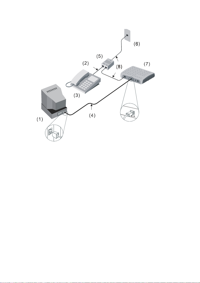
(1) Computer (2) RJ-11 Tel Cable (3) Phone (4) RJ-45 Ethernet Cable
(5) Splitter (6) Phone Jack (7) MT800 (8) RJ-11 Tel Cable
Figure 2-1 Computer to MT800 connection
2.2.3 Connecting Ethernet LAN to MT800
MT800 may be connected to any 10/100Base-TX Ethernet port.
When connecting MT800 to any Ethernet device that is capable of
operating at speeds higher than 10Mbps, be sure that the device has
auto-negotiation mode enabled for the connecting port.
Use cross-over cable to connect MT800 and the uplink port of a
switch or hub. Be sure that the cable connecting the LAN to MT800 is
not longer than 100 meters.
7
Page 18

2.3 Powering On MT800
1) Use the provided power adapter and plug it into a suitable
power source nearby.
2) You should see the Power LED indicator light up, which
indicates the device is powered on.
3) After a few seconds, look at the LAN LINK indicator and
make sure it with steady light, which indicates a valid
connection between the router and your computer.
8
Page 19
Chapter 3 Before Configuring
MT800
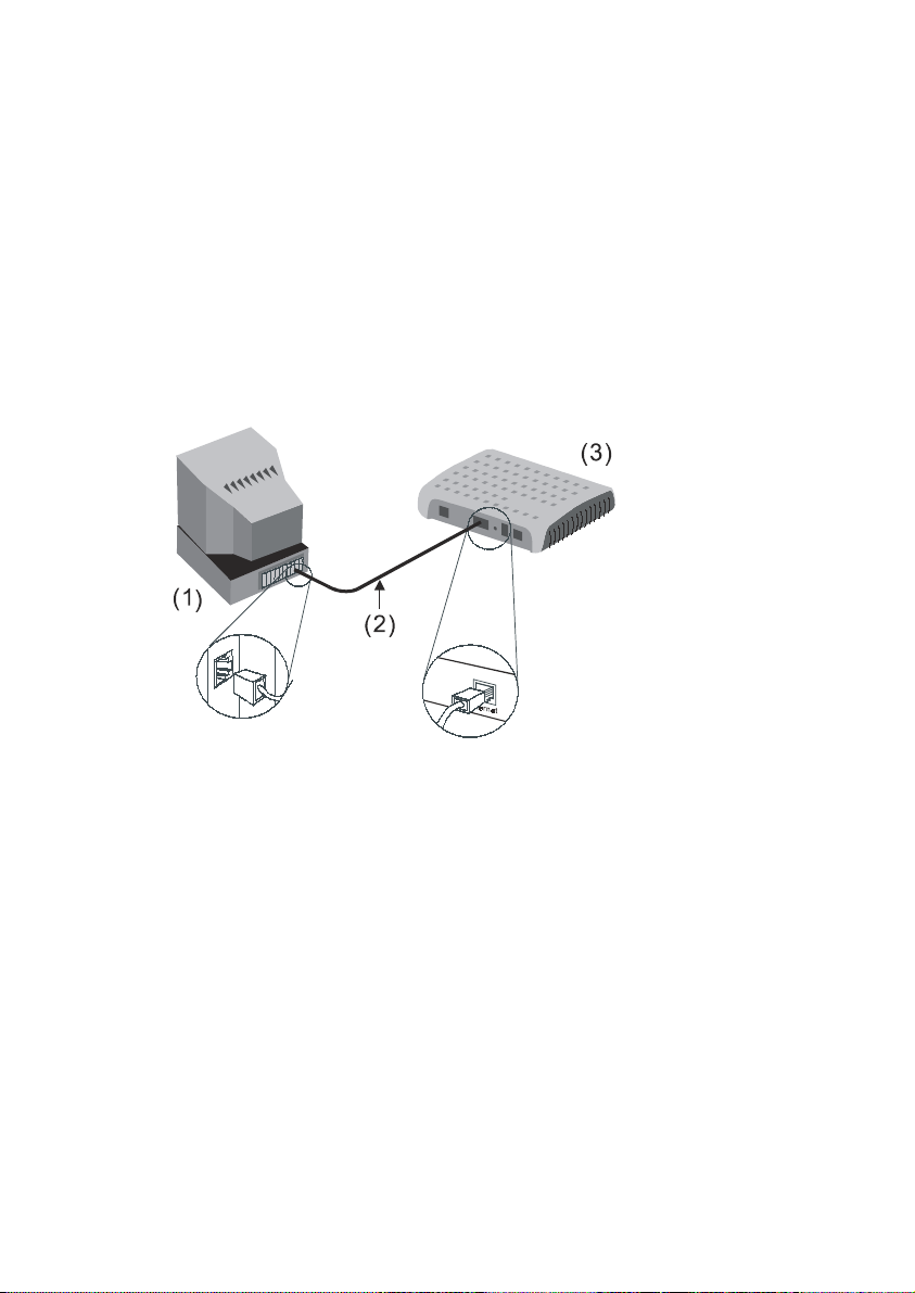
To configure MT800, you have to connect MT800 to a computer
as shown below. Use the provided straight-through cable.
(1)Computer (2)RJ-45 Ethernet Cable (3)MT800
Figure 3-1 Computer to MT800 connection
3.2 When to Configure the MT800
The factory default settings of MT800 have optimized all
functions, which made it can operate in most conditions of network.
Usually, for the users with simple network topology, the default
setting values can meet their basic requirements and need no
change.
9
Page 20

If the conditions of network have been changed by the
modification of security, scale, line of communication, protocol and
topology, for example, a demand of particular VPI and VCI, you
should adjust accordingly the default settings to be able to adapt to
the changes.
3.3 Configuring IP Settings on Your Computer
The steps of configure the IP settings are as below.
1) Understand the default IP settings for MT800: IP address
(192.168.1.1), Subnet mask (255.255.255.0).
2) Make sure your computer has the TCP/IP protocol installed
and enabled.
If you have an Ethernet port on your computer, it probably
z
already has TCP/IP protocol installed.
If you are using Windows XP, the TCP/IP is enabled by
z
default for standard installations.
3) Configure the IP address and Subnet mask of your
computer to make the computer set in the same subnet
with the MT800, for example, IP address:192.168.1.100,
Subnet mask: 255.255.255.0.
For computers running non-Windows operating systems,
follow the instructions for your OS to configure the IP setting to
occupy the same subnet as MT800.
3.4 Accessing the Web-based Configuration
Manager
Once the computer has IP settings that allow it to access the
Web-based configuration manager, you can change the factory
default settings to enable the MT800 to connect to the Internet.
10
Page 21

3.4.1 Checking for Proxy Service
If the browser software on the computer is configured to use a
proxy server for Internet access, it is necessary to first disable the
proxy connection.
In Windows Internet Explorer, you can check whether a proxy
server is enabled using the following procedures:
1) In the Explorer Window, select and click on
ToolsÆÆÆÆInternet Options, and enter the Internet Options
window.
2) In the Internet Options window, click the Connections
tab and click on the LAN Settings button.
3) Verify that the “Use proxy server” option is NOT checked. If
it is checked, click in the checked box to deselect the
option and click OK.
3.4.2 Applying the LAN IP Address of MT800
To access the Web-based configuration manager, launch your
Web browser and enter the LAN IP address of the MT800. For the
first access, the default LAN IP address of the MT800 is used. Type
in “http://” followed by the default IP address, “192.168.1.1” in the
address bar of the browser. The URL in the address bar should read:
http://192.168.1.1.
3.4.3 Inputting the User Name and Password
A new window appears prompting you for a user name and
password needed to access the Web-based configuration manager.
11
Page 22
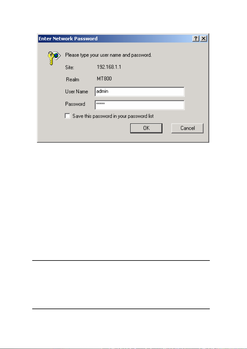
Figure 3-2 Enter user name and password
Use the default user name: admin and password: admin for
first time setup. You can change the password once you have
opened the Web-based configuration manager. The user name and
password allows any computer on the same subnet as the MT800 to
access the Web-based configuration manger. And this password can
also be used to Telnet to the device through the Ethernet or Internet
interfaces. To change this password, see Chapter 4 Web-based
Management.
Note:
Do not confuse the user name and password used to access the Web-based
manager with the ADSL account and password needed for PPP connections to
access your ISP’s network.
12
Page 23

Chapter 4 Web-based Management
This chapter describes how to use the web-based management
software to configure the MT800, which introduces the signification
of parameters and method of setting in the configuration interface.
The order of sectors is listed according to the functional configuration
interfaces.
4.1 Manager Interface Layout
The MT800 initially presents the System View page shown
below when you first log in.
The left part of the page is wizard column, and you can
z
enter the web page of configuration or management
through the hyperlink in wizard column.
The right part of the page is the practical domain of
z
configuration and management.
13
Page 24
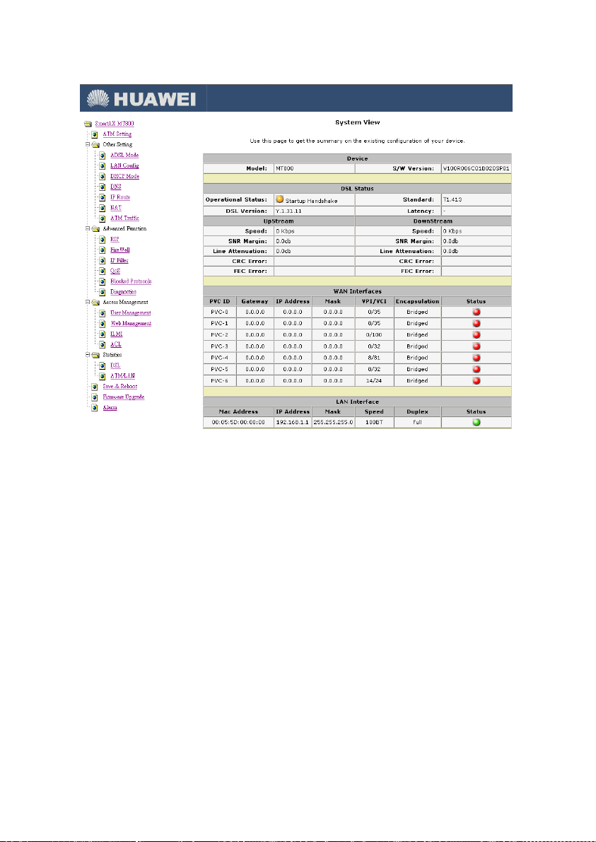
Figure 4-1 GUI of web-based configuration manager
14
Page 25
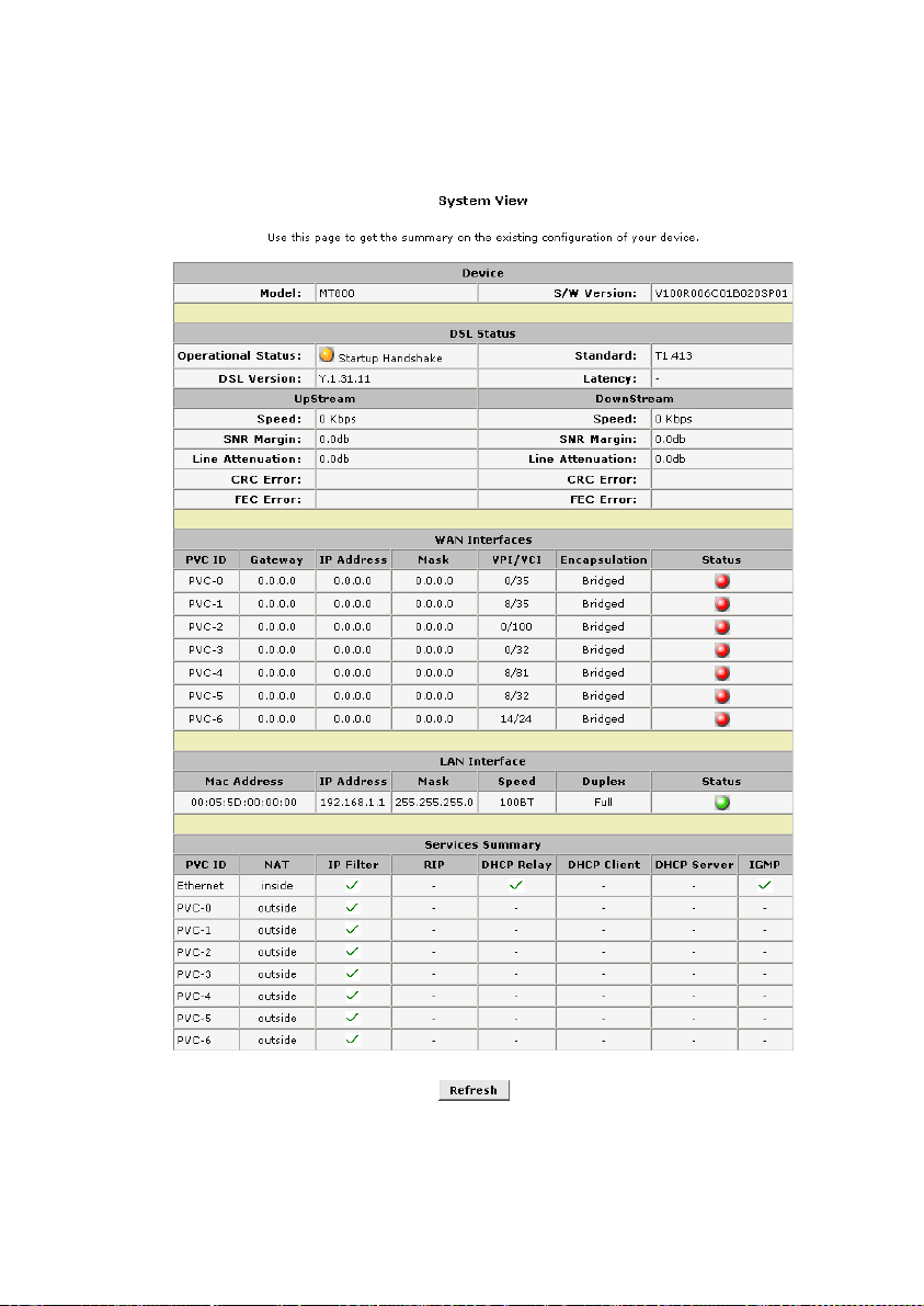
4.2 System View (Home Page)
Figure 4-2 Home Page – system view display
15
Page 26

The System View read-only table on the Home Page displays a
summary of various system settings and functions as described in
the table below.
Device: Displaying the basic information about the device
z
model and software versions.
DSL Status: Displaying the operational status, DSL
z
version, and performance statistics for the DSL line.
WAN Interfaces: Displaying the names and settings for
z
the device WAN interfaces. Multiple software-defined
interfaces may be configured to use the DSL connection. In
the WAN interface will display the PVC number, gateway,
IP address, mask, VPI/VCI, encapsulation and status.
LAN Interface: Displaying the names and various settings
z
of LAN interface, which include MAC address, IP address,
Mask, speed, duplex and status.
Services Summary: Displaying the following services that
z
the ADSL router performs to help you manage your
network: NAT, IP filter, RIP, DHCP status including DHCP
Relay, DHCP Server or DHCP Client, and IGMP.
4.3 ATM Setting
Click the hyperlink ATM Setting in wizard column to open the
ATM setting page.
There are three basic configuring modes for selection in this
web page: RFC2684 Bridged, RFC2684 Routed (IPoA) and PPP.
4.3.1 RFC2684 Bridged Connection
RFC2684 Bridged connections include three modes: Pure
Bridge, Static IP and DHCP.
16
Page 27

PVC: System provides 8 PVCs. Generally you can leave
z
this set at the default value 0. This option is also used to
create and configure new PVCs.
VPI: If you need any modification, please enter the VPI
z
value provided by ISP. See the attached table for all the
VPI default value of PVC.
VCI: If you need any modification, please enter the VCI
z
value provided by ISP. See the attached table for all the
VCI default value of PVC.
Operation Mode: This also should be left at the default
z
setting Enabled. This enables the PVC used for the initial
connection.
Encapsulation: You can select the mode LLC or VC MUX.
z
Address Type: The bridged connection modes include
z
Pure Bridge, Static IP and DHCP.
I.
Pure Bridge
The setting page displayed as below will appear while you
chose Pure Bridge mode. The gray items don’t need configuration.
17
Page 28
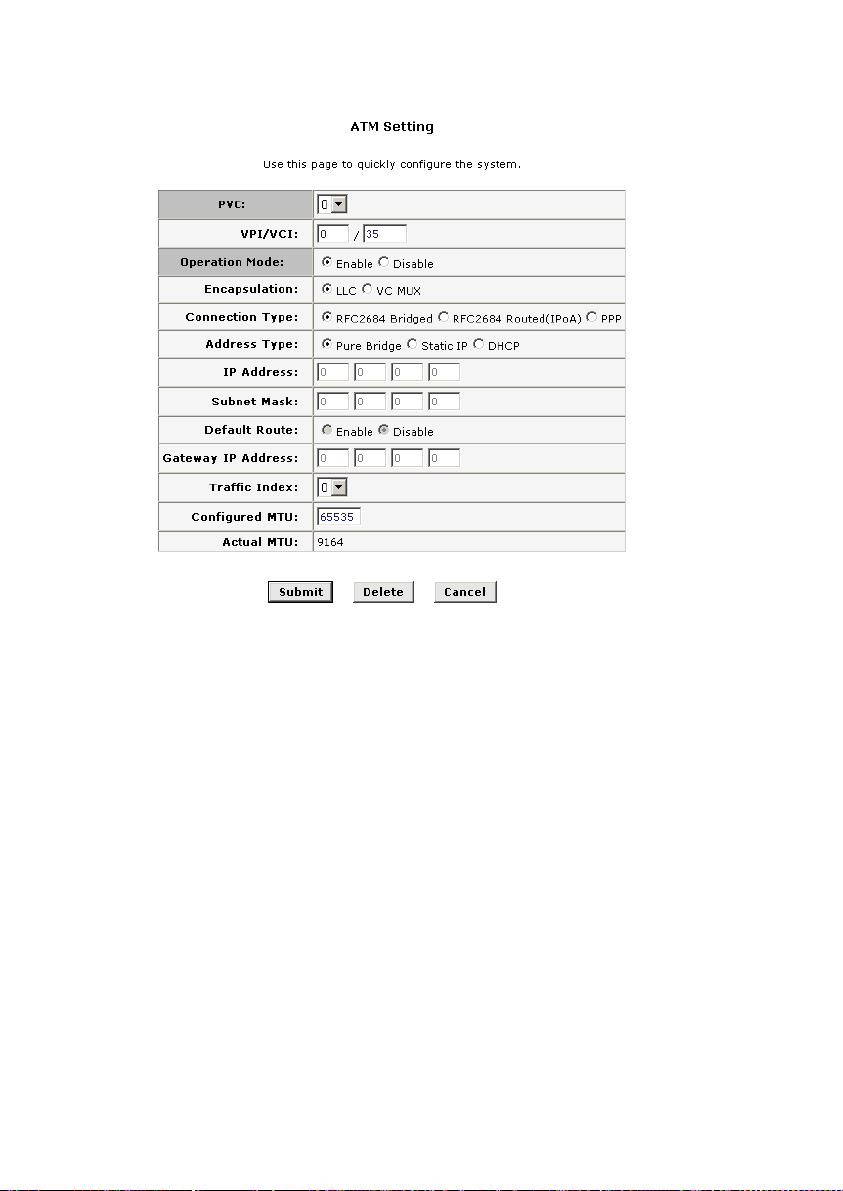
Figure 4-3 RFC2684 bridged connection-application of pure bridge
The RFC2684 bridged connection-application of pure bridge
mode displays a summary of various system settings and functions
as described below:
PVC: System provides 8 PVCs. Generally you can leave
z
this set at the default value 0. This option is also used to
create and configure new PVCs.
VPI: If you need any modification, please enter the VPI
z
value provided by ISP. See the attached table for all the
VPI default value of PVC.
18
Page 29

VCI: If you need any modification, please enter the VCI
z
value provided by ISP. See the attached table for all the
VCI default value of PVC.
Operation Mode: This also should be left at the default
z
setting Enabled. This enables the PVC used for the initial
connection.
Encapsulation: You can select the mode LLC or VC MUX.
z
Connection Type: The bridged connection modes include
z
Pure Bridge, Static IP and DHCP.
Traffic Index: Select the index number for ATM traffic from
z
the pull-down menu.
Configured MTU (Maximum Transmission Unit): Enter
z
the maximum bytes of the packet being transmitted during
connection.
II.
Static IP
The setting page displayed as below will appear while you
select Static IP setting mode. Please fill the corresponding field with
the IP address and network mask provided by ISP. The default
setting of route is “Disable”, and the Gateway IP address is “0.0.0.0.”
The recommended setting is to enable default route and enter the
Gateway IP address provided by ISP.
19
Page 30
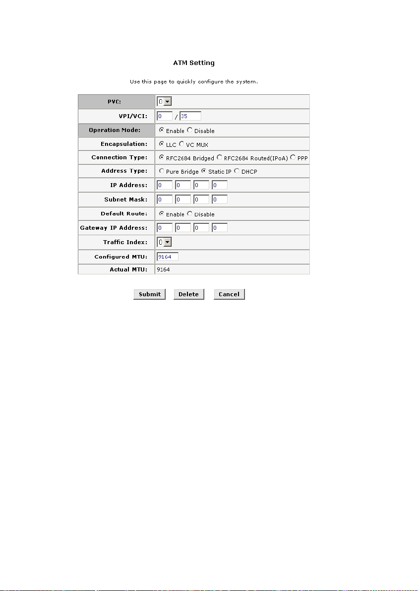
Figure 4-4 RFC2684 bridged connection-application of static IP
IP Address and Subnet Mask: Entered IP address and
z
subnet mask provided by ISP for the WAN interface of your
MT800.
Default Route: This setting specified the IP address below
z
is used for default route of LAN. The data will be sent
through WAN interface whenever a client LAN computer
accesses the Internet.
Gateway IP address: Enter the Gateway address
z
provided by ISP.
Traffic Index: Select the index number for ATM traffic from
z
the pull-down menu.
20
Page 31
Configured MTU: Enter the maximum bytes of the packet
z
being transmitted during connection.
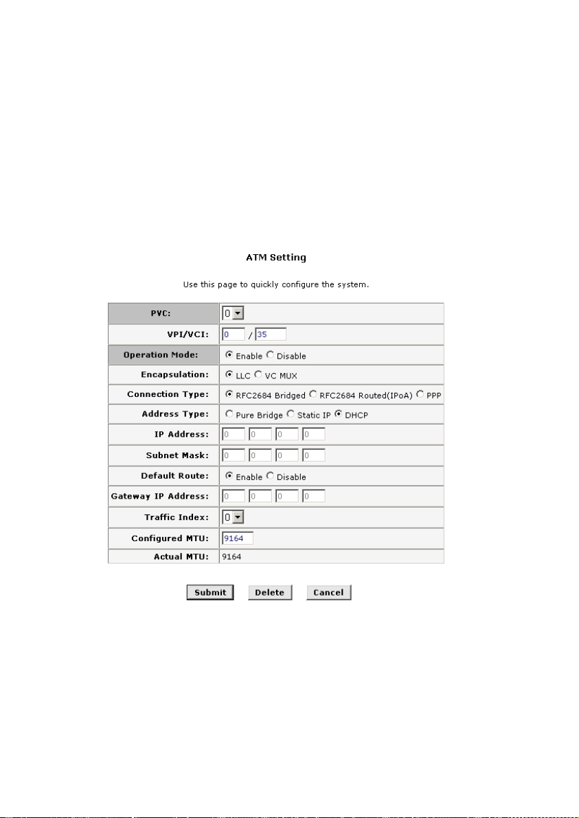
III.
DHCP
The setting page displayed as below will appear if you select
DHCP mode, which means automatically acquire IP address from
the DHCP sever of ISP.
Figure 4-5 RFC2684 Bridged Connection-application of DHCP
Default Route: This setting specified the IP address below
z
is used for default route of LAN. The data will be sent
21
Page 32

through WAN interface whenever a client LAN computer
accesses the Internet.
Gateway IP address: Enter the Gateway address
z
provided by ISP.
Traffic Index: Select the index number for ATM traffic from
z
the pull-down menu.
Configured MTU: Enter the maximum bytes of the packet
z
being transmitted during connection.
IV.
Save
Click the Submit button to save the settings in the RAM.
z
To save these configuration changes permanently, enter
z
the Save & Reboot page, select Save and click Submit
button to save new settings.
22
Page 33

4.3.2 RFC2684 Route (IPoA) Configuration
I.
Configuration page
Figure 4-6 RFC2684 route (IPoA) configuration
II.
Parameters explanation
PVC: The system provides 8 PVCs. Generally you can
z
leave this set at the default value 0. This option is also used
to create and configure new PVCs.
VPI: If you need any modification, please enter the VPI
z
value provided by ISP. See the attached table for all the
VPI default values of PVCs.
23
Page 34

VCI: If you need any modification, please enter the VCI
z
value provided by ISP. See the attached table for all the
VCI default values of PVCs.
Operation Mode: This also should be left at the default
z
setting Enabled. This enables the PVC used for the initial
connection.
Encapsulation: You can select the mode LLC or VC MUX.
z
IP Address and Subnet Mask: Enter the IP address and
z
subnet mask provided by ISP for the WAN interface of your
MT800.
Default Route: This setting specified the IP address below
z
is using for default route of LAN. The data will be sent
through WAN interface whenever a client LAN computer
accesses the Internet.
Gateway IP address: Enter the Gateway address
z
provided by ISP.
Traffic Index: Select the index number for ATM traffic from
z
the pull-down menu.
Configured MTU: Enter the maximum bytes of the packet
z
being transmitted during connection.
III.
Save
Click the Submit button to save the settings in the RAM.
z
To save these configuration changes permanently, enter
z
the Save & Reboot page, select Save and click Submit
button to save new settings.
4.3.3 PPP Configuration
There are two options for PPP configuration: PPPoA and
PPPoE.
24
Page 35

I.
PPPoA
Figure 4-7 PPP configuration-PPPoA
PVC: System provides 8 PVCs. Generally you can leave
z
this set at the default value 0. This option is also used to
create and configure new PVCs.
VPI: If you need any modification, please enter the VPI
z
value provided by ISP. See the attached table for all the
VPI default value of PVC.
25
Page 36

VCI: If you need any modification, please enter the VCI
z
value provided by ISP. See the attached table for all the
VCI default value of PVC.
Operation Mode: This also should be left at the default
z
setting Enabled. This enables the PVC used for the initial
connection.
Encapsulation: You can select the mode LLC or VC MUX.
z
Connection Type: The bridged connection modes include
z
Pure Bridge, Static IP and DHCP.
PPPoA / PPPoE: Select PPPoA.
z
IP Unnumber: You can select enable or disable. When
z
Enabled is selected, the Ethernet port address will be used
as your IP address.
Traffic Index: Select the index number for ATM traffic from
z
the pull-down menu.
Configured MTU: Enter the maximum bytes of the packet
z
being transmitted during connection.
26
Page 37

II.
PPPoE
Figure 4-8 PPP configuration-PPPoE
PVC: The system provides 8 PVCs. Generally you can
z
leave this set at the default value 0. This option is also used
to create and configure new PVCs.
VPI: If you need any modification, please enter the VPI
z
value provided by ISP. See the attached table for all the
VPI default value of PVC.
27
Page 38

VCI: If you need any modification, please enter the VCI
z
value provided by ISP. See the attached table for all the
VCI default value of PVC.
Operation Mode: This also should be left at the default
z
setting Enabled. This enables the PVC used for the initial
connection.
Encapsulation: You can select the mode LLC or VC MUX.
z
PPPoA / PPPoE: Please select “PPPoE”.
z
IP Unnumber: You can select enable or disable. When
z
Enabled is selected, the Ethernet port address will be used
as your IP address.
Traffic Index: Select the index number for ATM traffic from
z
the pull-down menu.
Default Route: This setting specified the IP address below
z
is using for default route of LAN. The data will be sent
through WAN interface whenever a client LAN computer
accesses the Internet.
Username and Password: Enter the username and
z
password provided by ISP.
Use DNS: It is recommended to keep this option as Enable,
z
indicating that when PPP dial applies for IP and gateway, it
also tries for DNS server IP at the same time. On the other
hand, keep this option as disable, indicating that obtaining
DNS server not from PPP dial, and needed to manually
type in the addresses of primary DNS server and
secondary DNS server on the DNS configuration page.
Configured MTU: Enter the maximum bytes of the packet
z
being transmitted during connection.
28
Page 39

III.
PPP Interface
After modification, click on Submit button, a Status entry will be
added to the configuration page. Please click on
icon to reveal
PPP Interface page.
The PPP interface is shown in Fig. 4-9 below.
Figure 4-9 PPP Interface
WAN IP Address
z
Displays the IP address of WAN port on
PPP interface.
Gateway IP Address
z
Displays the IP address of the
gateway on PPP interface.
Status
z
Idle Timeout Disconnection (Mins)
z
Displays the work status of PPP interface.
It is to specify the
time length (in minutes) of the idle PPP interface before it is
to be automatically disconnected, i.e. If the idle time of
PPP interface exceeds the configured value, PPP
connection will be automatically cut off by system.
z
Operation
There are three options of Connect, Auto
Connect (default) and Manual.
29
Page 40

Connect If it is selected, MT800 will automatically
z
enable the PPP dial connection each time the device
is powered on.
Auto Connect
z
If it is selected, MT800 will
automatically redial after timing out and the
disconnection is executed.
z
Manual
If it is selected, you need to establish the
PPP dial connection manually by clicking on Connect
button.
IV.
Save
Click the Submit button to save the settings in the RAM.
z
Click the Submit button to save the settings in the RAM.
z
To save these configuration changes permanently, enter
z
the Save & Reboot page, select Save and click Submit
button to save new settings.
4.4 ADSL Mode Configuration
Click the ADSL Mode of Other Setting in the Wizard column to
set the ADSL mode. Usually the ADSL mode is set to the default
value
Multimode
, and does not need to be changed. If your ISP
instructs you to change your ADSL settings, choose the appropriate
ADSL mode in this web page.
30
Page 41

I.
Configuration page
Figure 4-10 ADSL mode configuration
II.
Save
Click the Submit button to save the settings in the RAM.
z
To save these configuration changes permanently, enter
z
the Save & Reboot page, select Save and click Submit
button to save new settings.
4.5 LAN Configuration
Click the LAN Configuration of Other Setting in the Wizard
Column to set the LAN interface. The LAN IP address identifies the
LAN port (eth-0) as a node on your network; that is, its LAN IP
address must be in the same subnet as the computers on your LAN.
You can change the default LAN IP address and Net Mask to
suit for your LAN.
31
Page 42

I.
Configuration page
Figure 4-11 LAN configuration
II.
Parameter explanation
To change the LAN IP address, click the Refresh button and
type in the new settings as described below.
LAN IP Address: Type in the IP address for the Ethernet
z
LAN interface. The default IP address is 192.168.1.1
LAN Network Mask: Type in the Subnet Mask for the
z
Ethernet LAN IP interface. The default Mask is
255.255.255.0
Note:
The public IP address that ISP assigned is not LAN IP address. The public IP
address identifies the WAN interface that the ADSL router connects to Internet.
32
Page 43

III.
Save
Click the Submit button to save the settings in the RAM.
z
To save these configuration changes permanently, enter
z
the Save & Reboot page, select Save and click Submit
button to save new settings.
Note:
If you change the IP address, you need login in again.
4.6 DHCP Mode Configuration
Click the DHCP Mode of Other Setting in the Wizard Column
to set the DHCP mode. DHCP services that provided by MT800
include: directly provide DHCP service, receive and relay DHCP
service.
I.
None DHCP
The default setting is None, which disable DHCP services. In
this case, ADSL terminal device shall be assigned IP settings
manually or through the DHCP server of LAN or ISP.
Figure 4-12 DHCP mode configuration-None
33
Page 44

II.
DHCP Server
MT800 can be configured as DHCP server of LAN. Then the
ADSL terminal shall provide IP settings for your PC.
Figure 4-13 DHCP mode configuration-DHCP Server
Start/End IP Address: The range of IP addresses that
z
release by DHCP server.
Gateway Address: The IP address of gateway for DHCP
z
server.
Status: Show the status of DHCP server.
z
Action(s): Click icon
z
click icon
to delete an added DHCP server; Click icon
to modify the added DHCP server;
to view the parameters of an existed DHCP server.
III.
DHCP Relay
MT800 can also to be configured to relay DHCP packets, and
the PC shall be assigned IP address automatically.
34
Page 45

Figure 4-14 DHCP mode configuration-DHCP Relay
DHCP Server Address: Input the assigned address in the
z
field.
Interfaces Running DHCP Relay: Please select the eth
z
value from pull-down menu, and click Add button as well.
Action(s): Click icon
z
to delete an added DHCP relay.
IV.
Save
Click the Submit button to save the settings in the RAM.
z
To save these configuration changes permanently, enter
z
the Save & Reboot page, select Save and click Submit
button to save new settings.
4.7 DNS Configuration
Click the DNS of Other Setting in the Wizard Column to set the
DNS. Multiple DNS addresses are useful to provide alternatives
when one of the servers is down or encountering heavy traffic. ISPs
35
Page 46

typically provide primary and secondary DNS addresses, and may
provide additional addresses.
I.
Configuration page
Figure 4-15 DNS configuration
II.
Save
Click the Submit button to save the settings in the RAM.
z
To save these configuration changes permanently, enter
z
the Save & Reboot page, select Save and click Submit
button to save new settings.
36
Page 47

4.8 IP Route Table Configuration
Click the IP Route of Other Setting in the W izard Colum n to set
the IP Route Table.
IP Routes are used to define gateways and hops used to route
data traffic. Most users will not need to use this feature as the
previously configured default gateway and LAN IP settings on your
host computers should be sufficient.
You may need to define routes if your LAN includes two or more
networks or subnets, if you connect to two or more ISP services, or if
you connect to a remote corporate LAN. Use the IP Route Table to
add new IP routes.
I.
Configuration page
Figure 4-16 IP Route Table
II.
Parameter explanation
Destination: Specifying the IP address of the destination
z
computer. The destination can specify the IP address of a
specific computer or an entire network. It can also be
specified as all zeros to indicate that this route should be
37
Page 48

used for all destinations for which no other routes are
defined (this is the route that creates the default gateway).
Netmask: Indicating which parts of the destination address
z
refer to the network and which parts refer to a computer on
the network. The default gateway uses a netmask of
0.0.0.0.
Next Hop: Specifying the next IP address to send data to
z
when its final destination is that shown in the destination
column.
IF Name: Displaying the name of the interface through
z
which to data is forwarded to the specified next hop.
Route Type: Displaying whether the route is direct or
z
indirect. In a direct route, the source and destination
computers are on the same network, and the MT800
attempts to directly deliver the data to the computer. In an
indirect route, the source and destination computers are on
different networks, and the MT800 forwards data to a
device on another network for further handling.
Route Origin: Displaying the origin of the route. Dynamic
z
indicates the route automatically produced by the device
interface address. Routes you create are labeled
Local.
Other routes learned from route protocol are labeled the
name of the corresponding route protocol (for example,
origin of the route learned from RIP is labeled RIP).
III.
Save
Click the Submit button to save the settings in the RAM.
z
To save these configuration changes permanently, enter
z
the Save & Reboot page, select Save and click Submit
button to save new settings.
38
Page 49

4.9 NAT Configuration
Network Address Translation (NAT) is a method for disguising
the private IP addresses on your LAN as the public IP address on the
Internet. You define NAT rules that specify exactly how and when to
translate between public and private IP addresses.
Click the NAT of Other Setting in the Wizard Column to set the
NAT. NAT is enabled by default. You can enable or disable NAT by
selecting the Enable or Disable option in the configuration page and
submitting the settings.
I.
Configuration page
Figure 4-17 NAT configuration
To configure NAT Rules, click the Add button. A new window is
displayed. From the Rule Flavor drop-down list, select NAPT, DMZ,
and REDIRECT. The page redisplays with only the fields that are
appropriate for the chosen NAT flavor as Figure 4-18, Figure 4-19
and Figure 4-20.
39
Page 50

Figure 4-18 Add NAPT rule
Figure 4-19 Add DMZ rule
40
Page 51

Figure 4-20 Add REDIRECT rule
II.
Parameter explanation
The explanation of parameters in the above windows is as
below.
NAT Configuration:
Rule ID: The Rule ID determines the order in which rules
z
are invoked (the lowest numbered rule is invoked first, and
so on). In some cases, two or more rules may be defined to
act on the same set of IP addresses. Be sure to assign the
Rule ID so that the higher priority rules are invoked before
lower-priority rules. It is recommended that you select rule
IDs as multiples of 5 or 10 so that, in the future, you can
insert a rule between two existing rules.
IF Name: Displays the name of the interface.
z
Rule Flavor: There are three rules you can select:
z
REDIRECT, DMZ, and NAPT.
41
Page 52

Protocol: This selection specifies which type of Internet
z
communication will be subject to this translation rule. You
can select TCP or UDP.
Local IP From: Type the starting IP of the range of private
z
address you want to be translated. You can specify that
data from all LAN addresses should be translated by typing
0 (zero) in each From field and 255 in each To field. Or,
type the same address in both fields if the rule only applies
to one LAN computer.
Local IP To: Type the ending IP of the range of private
z
address you want to be translated.
Action: Check or delete the rule.
z
Add NAPT Rule:
Local IP From: Type the starting IP of the range of private
z
address you want to be translated. You can specify that
data from all LAN addresses should be translated by typing
0 (zero) in each From field and 255 in each To field. Or,
type the same address in both fields if the rule only applies
to one LAN computer.
Local IP To: Type the ending IP of the range of private
z
address you want to be translated.
Add DMZ Rule:
Local IP: Type the private IP address you want to be
z
translated.
Add REDIRECT Rule:
Protocol: This selection specifies which type of Internet
z
communication will be subject to this translation rule. You
can select TCP or UDP.
Local IP: Type the private IP address you want to be
z
translated.
42
Page 53

Destination Port From: Enter the starting port ID (or a
z
range) that you expect to see on incoming packets
destined for the LAN computer for which this rule is being
created. With the ending port ID (or a range) specified in
the next field, incoming traffic that meets these criteria will
be redirected to the Local Port number you specified.
Destination Port To: Enter the ending port ID (or a range).
z
III.
Save
Click the Submit button to save the settings in the RAM.
z
To save these configuration changes permanently, enter
z
the Save & Reboot page, select Save and click Submit
button to save new settings.
4.10 ATM Traffic
ATM traffic is the traffic at asynchronous transfer mode.
Click the ATM Traffic of Other Setting in the Wizard Column to
configure the ATM traffic description.
I.
Configuration page
Figure 4-21 ATM traffic
43
Page 54

II.
Parameters explanation
Traffic Id: The ID number of ATM traffic.
z
Type: The traffic type of created ATM.
z
Service Category: The service category of created ATM.
z
Creator: The creator’s name.
z
Action(s): Click icon
z
table; Click icon
to delete an existed ATM from
to view the parameters of an existed
DHCP server.
Add: Click on Add to add a new traffic id.
z
Refresh: Click on Refresh to view the latest changes of
z
configuration.
4.11 RIP Configuration
RIP is an Internet protocol. You can set up to share routing table
information with other routing devices on your LAN, at your ISP's
location, or on remote networks connected to your network via the
ADSL line.
Click the RIP of Advanced Function in the Wizard Column to
set the RIP.
44
Page 55

I.
Configuration page
Figure 4-22 RIP configuration
II.
Change RIP configuration:
1) If necessary, change the Age and Update Time. These
are global settings for all interfaces that use RIP.
Age is the amount of time in seconds that the device's RIP
z
table will retain each route that it learns from adjacent
computers.
Update Time specifies how frequently the MT800 will send
z
out its routing table to its neighbors.
2) In the IF Name column, select the name of the interface on
which you want to enable RIP.
3) Select a Metric value for the interface. RIP uses a "hop
count" as a way to determine the best path to a given
destination in the network. The hop count is the sum of the
metric values assigned to each port through which data is
passed before reaching the destination. Among several
45
Page 56

alternative routes, the one with the lowest hop count is
considered the fastest path.
4) Select Send Mode and Receive Mode.
The Send Mode setting indicates the RIP version this
z
interface will use when it sends its route information to
other devices.
The Receive Mode setting indicates the RIP version(s) in
z
which information must be passed to the MT800 in order
for it to be accepted into its routing table.
5) Click the Add button. The new RIP entry will display in the
table.
6) Click the Enable radio button to enable the RIP feature.
Note:
z
RIP version 1 is the original RIP protocol. Select RIP1 if you have devices that
communicate with this interface that understand RIP version 1 only.
z
RIP version 2 is the preferred selection because it supports "classless" IP
addresses (which are used to create subnets) and other features. Select RIP2 if
all other routing devices on your LAN support this version of the protocol.
III.
Save
Click the Submit button to save the settings in the RAM.
z
To save these configuration changes permanently, enter
z
the Save & Reboot page, select Save and click Submit
button to save new settings.
46
Page 57

4.12 Firewall Configuration
4.12.1 Configuration of Global Firewall
The Firewall enables you to protect the system against denial of
service (DoS) attacks and other types of malicious accesses to your
LAN. You can also specify how to monitor attempted attacks, and
who should be automatically notified.
Click the Firewall of Advanced Function in the Wizard Column
to set the RIP.
I.
Configuration page
Figure 4-23 Firewall configuration
47
Page 58

II.
Parameter explanation
Follow these instructions to configure global firewall settings.
Configure any of the following settings that display in the
Firewall Global Configuration table:
Blacklist Status: If you want the device to maintain and
z
use a black list, click
Enable
. Click
Disable
if you do not
want to maintain a list.
Blacklist Period(min): Specifying the number of minutes
z
that a computer's IP address will remain on the black list
(i.e., all traffic originating from that computer will be
blocked from passing through any interface on the MT800).
For more information, see Managing the Black List below.
Attack Protection: Click the Enable radio button to use
z
the built-in firewall protections that prevent the following
common types of attacks:
IP Spoofing: Sending packets over the WAN
z
interface using an internal LAN IP address as the
source address.
Tear Drop: Sending packets that contain overlapping
z
fragments.
Smurf and Fraggle: Sending packets that use the
z
WAN or LAN IP broadcast address as the source
address.
Land Attack: Sending packets that use the same
z
address as the source and destination address.
Ping of Death: Illegal IP packet length.
z
DoS Protection: Click the Enable radio button to use the
z
following denial of service protections: SYN DoS, ICMP
DoS, Per-host DoS protection.
48
Page 59

Max Half open TCP Connection: Set the percentage of
z
concurrent IP sessions that can be in the half-open state.
In ordinary TCP communication, packets are in the
half-open state only briefly as a connection is being
initiated; the state changes to active when packets are
being exchanged, or closed when the exchange is
complete. TCP connections in the half-open state can use
up the available IP sessions. If the percentage is exceeded,
then the half-open sessions will be closed and replaced
with new sessions as they are initiated.
Max ICMP Connection: Set the percentage of concurrent
z
IP sessions that can be used for ICMP messages. If the
percentage is exceeded, then older ICMP IP sessions will
be replaced by new sessions as they are initiated.
Max Single Host Connection: Set the percentage of
z
concurrent IP session that can originate from a single
computer. This percentage should take into account the
number of hosts on the LAN.
III.
Save
Click the Submit button to save the settings in the RAM.
z
To save these configuration changes permanently, enter
z
the Save & Reboot page, select Save and click Submit
button to save new settings.
4.12.2 Managing the Blacklist
If data packets are received that violate the firewall settings or
any of the IP Filter rules, then the source IP address of the offending
packets can be blocked from such accesses for a specified period of
time. The source computer remains on the black list for the period of
49
Page 60

time that you specify. You can enable or disable use of the black list
using the settings described above.
To view the list of currently blacklisted computers, click the
Black List button at the bottom of the Firewall Configuration page.
The table displays the following information for each entry.
Host IP Address: The IP address of the computer that
z
sent the packet(s) that caused the violation.
Reason: A short description of the type of violation. If the
z
packet violated an IP Filter rule, the custom text from the
Log Tag field will display.
IPF Rule ID: If the packet violated an IP Filter rule, this field
z
will display the ID assigned to the rule.
4.13 IP Filter Configuration
The IP filter feature enables you to create rules that control the
forwarding of incoming and outgoing data between your LAN and the
Internet and within your LAN.
4.13.1 IP Filter Global Settings
The IP Filter Configuration page displays global settings that
you can modify. And the IP Filter rule table shows all currently
established rules.
Click the IP Filter of Advanced Function in the Wizard Column
to set the IP filter.
50
Page 61

I.
Configuration page
Figure 4-24 IP filter configuration
II.
Parameter explanation
Security Level: This setting determines which IP Filter
z
rules take effect, based on the security level specified in
each rule. For example, when High is selected, only those
rules that are assigned a security value of High will be in
effect. The same is true for the Medium and Low settings.
When None is selected, IP Filtering is disabled.
Private/Public Default Action: This setting specifies a
z
default action to be taken (Accept or Deny) on private or
public-type device interfaces when they receive packets
that do not match any of the filtering rules. You can specify
a different default action for each interface type. (You
specify an interface's type when you create the interface;
see 4.3.3 PPP Configuration, for example.)
A public interface typically connects to the Internet. PPP and
IPoA interfaces are typically public. Packets received on a public
interface are subject to the most restrictive set of firewall protections
defined in the software. Typically, the global setting for public
51
Page 62

interfaces is Accept, so that all accesses to your LAN initiated from
external computers are denied (discarded at the public interface),
except for those allowed by a specific IP Filter rule.
A private interface connects to your LAN, such as the Ethernet
interface. Packets received on a private interface are subject to a
less restrictive set of protections, because they originate within the
network. Typically, the global setting for private interfaces is Accept,
so that LAN computers have access to the Internet connection.
Ensure that the Security Level and Private/Public Default Action
settings on the IP Filter Configuration page are configured as needed,
and then click the Submit button. A page displays to confirm your
changes.
4.13.2 Adding an IP Filter Rule
To create the IP filter rule, and set the rule as it must be suit for
various standard while transfer the rule. To add new IP filter rule
using these commands:
On the main IP Filter page, click the Add button to display the IP
Filter Rule - Add page. Enter or select data for each field that applies
to your rule. The following figure describes the fields.
52
Page 63

I.
Configuration page
Figure 4-25 Add IP filter rule
53
Page 64

II.
Parameter explanation
Rule ID: Each rule must be assigned a sequential ID
z
number. Rules are processed from lowest to highest on
each data packet, until a match is found. It is
recommended that you assign rule IDs in multiples of 5 or
10 (e.g., 10, 20, 30) so that you leave enough room
between them for inserting a new rule if necessary.
Action: Specifying what the rule will do to a packet when
z
the packet matches the rule criteria. The action can be
Accept
(forward to destination) or
(discard the
Deny
packet).
Direction: Specifying whether the rule should apply to data
z
packets that are incoming or outgoing on the selected
interface. Incoming refers to packets coming in to the LAN
on the interface, and Outgoing refers to packets going out
from the LAN. You can use rules that specify the incoming
direction to restrict external computers from accessing
your LAN.
Interface: The interface on the device on which the rule will
z
take effect.
In Interface: The interface from which packets must have
z
been forwarded to the interface specified in the previous
selection. This option is valid only on rules defined for the
outgoing direction.
Log Option: When Enabled is selected, a log entry will be
z
created on the system each time this rule is invoked. The
log entry will include the time of the violation, the source
address of the computer responsible for the violation, the
destination IP address, the protocol being used, the source
and destination ports, and the number of violations
54
Page 65

occurring in the previous x minutes. (Logging may be
helpful when troubleshooting.) This information can also be
e-mailed to administrators.
Security Level: The security level that must be enabled
z
globally for this rule to take affect. A rule will be active only
if its security level is the same as the globally configured
setting (shown on the main IP Filter page). For example, if
the rule is set to Medium and the global firewall level is set
to Medium, then the rule will be active; but if the global
firewall level is set to High or Low, then the rule will be
inactive.
Black List Status: Specifies whether or not a violation of
z
this rule will result in the offending computer's IP address
being added to the Black List, which blocks the MT800
from forwarding packets from that source for a specified
period of time.
Log Tag: A description of up to 16 characters to be
z
recorded in the log in the event that a packet violates this
rule. Be sure to set the Log Option to Enable if you
configure a Log Tag.
Start/End Time: The time range during which this rule is to
z
be in effect, specified in military units.
Src IP Address: IP address criteria for the source
z
computer(s) from which the packet originates. In the
drop-down list, you can configure the rule to be invoked on
packets containing:
any: any source IP address.
z
lt: any source IP address that is numerically less than
z
the specified address.
lteq: any source IP address that is numerically less
z
than or equal to the specified address.
55
Page 66

gt: any source IP address that is numerically greater
z
than the specified address.
gteq: any source IP address that is numerically
z
greater than or equal to the specified address.
eq: any source IP address that is numerically equal to
z
the specified address.
neq: any source IP address that is not equal to the
z
specified address.
range: any source IP address that is within the
z
specified range, inclusive.
out of range: any source IP address that is outside
z
the specified range.
self: the IP address of the MT800 interface on which
z
this rule takes effect.
Dest IP Address: IP address criteria for the destination
z
computer(s) (i.e., the IP address of the computer to which
the packet is being sent). In addition to the options
described for the Src IP Address field, the following option
is available:
bcast: specifies that the rule will be invoked for any
z
packets sent to the broadcast address for the
receiving interface. When you select this option, you
do not need to specify the address, so the address
fields are dimmed.
Protocol: IP protocol criteria that must be met for rule to be
z
invoked. You can specify that packets must contain the
selected protocol (eq), that they must not contain the
specified protocol (
regardless of the protocol (
), or that the rule can be invoked
neq
). TCP, UDP, and ICMP are
any
commonly used IP protocols; others can be identified by
56
Page 67

number, from 0-255, as defined by the Internet Assigned
Numbers Authority (IANA).
Apply Inspection: If this option is enabled, then Stateful
z
Filtering is performed and the rule is also applied in the
other direction on the given interface during an IP session.
Source Port: Port number criterion for the computer(s)
z
from which the packet originates. This field will be dimmed
(unavailable for entry) unless you have selected TCP or
UDP as the protocol. See the description of Src IP Address
for the selection options.
Dest. Port: Port number criterion for the destination
z
computer(s) (i.e., the port number of the type of computer
to which the packet is being sent). This field will be dimmed
(unavailable for entry) unless you have selected TCP or
UDP as the protocol. See the description of Src IP Address
for the selection options.
TCP Flag: Specifies whether the rule should apply only to
z
TCP packets that contain the synchronous (SYN) flag, or to
all TCP packets. This field will be dimmed (unavailable for
entry) unless you selected TCP as the protocol.
ICMP Type: Specifies whether the value in the type field in
z
ICMP packet headers will be used as a criterion. The value
can be any decimal value from 0-255. You can specify that
the value must equal (eq) or not equal (neq) to the
specified value, or you can select any to enable the rule to
be invoked on all ICMP packets. This field will be dimmed
(unavailable for entry) unless you specify ICMP as the
protocol.
ICMP Code: Specifies whether the value in the code field
z
in ICMP packet headers will be used as a criterion. The
code value can be any decimal value from 0-255. You can
57
Page 68

specify that the value must equal (eq) or not equal (
the specified value, or you can select any to enable the
rule to be invoked on all ICMP packets. This field will be
dimmed (unavailable for entry) unless you specify ICMP as
the protocol.
IP Frag Pkt: Determines how the rule applies to IP packets
z
that contain fragments. You can choose from the following
options:
Yes: The rule will be applied only to packets that
z
contain fragments.
No: The rule will be applied only to packets that do not
z
contain fragments
Ignore: (Default) The rule will be applied to packets
z
whether or not they contain fragments, assuming that
they match the other criteria.
IP Option Pkt: Determines whether the rule should apply
z
to IP packets that have options specified in their packet
headers.
Yes: The rule will be applied only to packets that
z
contain header options.
No: The rule will be applied only to packets that do not
z
contain header options.
Ignore: (Default) The rule will be applied to packets
z
whether or not they contain header options, assuming
that they match the other criteria.
Packet Size: Specifies that the IP Filter rule will take affect
z
only on packets whose size in bytes matches this criterion.
(lt = less than, gt = greater than,
= less than or equal
lteq
to.)
neq
)
58
Page 69

When you are done selecting criteria, ensure that the Enable
button is selected at the top of the page, and then click the Submit
button at the bottom of the page. After a confirmation page displays,
the IP Filter -Configuration page will redisplay with the new rule
showing in the table.
III.
Save
Click the Submit button to save the settings in the RAM.
z
To save these configuration changes permanently, enter
z
the Save & Reboot page, select Save and click Submit
button to save new settings.
4.14 QoS
Various applications that operated in MT800 have different
requirement of priority level. Different applications will be classified
by MT800 according to the different requirement of priority level, and
the different priority level will be provided to each level with mode of
Diffserv. MT800 sets the individual queue for each priority level, and
then controls the output of each queue of priority.
Click the QoS of Advanced Function in the Wizard Column to
set the priority level to the applications that operated in MT800.
The available options of QoS include: Application, TOS, Diffserv,
802.1p, and VLAN Tag.
59
Page 70

I.
No QoS
Figure 4-26 QoS-No QoS
II.
Application
Some special application, such as network game,
videoconference, network phone, will transmit the audio, video and
data synchronously. So you can set the priority level to the different
type of traffic. So the traffic with higher priority will be processed
firstly while the network jammed.
Figure 4-27 QoS-Application
60
Page 71

Priority Queue Index: Provided 4 priority queues. MT800
z
will set the received traffic into one of 4 priority queues for
output. The packet with highest priority will be outputted
firstly. If this queue is empty, the next packet with highest
priority will be outputted, the rest may be deduced by
analogy.
Weight: To set the weight value to the parameters of
z
selected application. The larger number of weight value is,
the higher priority it has.
Application Type: Select the application type from pull
z
down menu, which include: Voice, Video, IGMP, and Data.
RTP: Enter the start and end port number in the blank of
z
Voice Data Start/End Port and Video Data Start/End
Port.
III.
TOS
ToS is an 8-bit field, and also the second field of header group in
IP packet. It is consist of two sub-fields: priority level sub-field and
service type sub-field. The priority level sub-field will assign the
priority for group within the queue. The group with higher priority will
be sent firstly.
61
Page 72

Figure 4-28 QoS-TOS
Priority Queue Index: Provided 4 priority queues. MT800
z
will set the received traffic into one of 4 priority queues for
output. The packet with highest priority will be outputted
firstly. If this queue is empty, the next packet with highest
priority will be outputted, the rest may be deduced by
analogy.
Weight: To set the weight value to the parameters of
z
selected application. The larger number of weight value is,
the higher priority it has.
TOS Range: Select the priority range of field from pull
z
down menu.
IV.
DiffServ
DiffServ field was defined in RFC 2474 and 2475 that in order to
replace ToS field. DiffServ integrated edge monitor & management,
assignment and service priority. DiffServ provide different service
priority to different requirement of QoS, in order to meet the
requirement of different service.
62
Page 73

Figure 4-29 QoS-DiffServ
Priority Queue Index: Provided 4 priority queues. MT800
z
will set the received traffic into one of 4 priority queues for
output. The packet with highest priority will be outputted
firstly. If this queue is empty, the next packet with highest
priority will be outputted, the rest may be deduced by
analogy.
Weight: To set the weight value to the parameters of
z
selected application. The larger number of weight value is,
the higher priority it has.
DiffServ Range: Select the priority range from pull down
z
menu.
V.
802.1p
The label of 802.1p specified 8 settings of priority weight form 0
(Lowest) to 7 (Highest). MT800 will determine the priority queue of
traffic according to these labs of priority weight.
63
Page 74

Figure 4-30 QoS-802.1p
Priority Queue Index: Provided 4 priority queues. MT800
z
will set the received traffic into one of 4 priority queues for
output. The packet with highest priority will be outputted
firstly. If this queue is empty, the next packet with highest
priority will be outputted, the rest may be deduced by
analogy.
Weight: To set the weight value to the parameters of
z
selected application. The larger number of weight value is,
the higher priority it has.
802.1p Range: Select the priority range from pull down
z
menu.
VI.
VLAN Tag
VLAN Tag is a hexadecimal number, which added to the packet
that transmitted in VLAN. The VLAN Tag is to indicate which VLAN is
the packet belongs to. Thus, the packet with the specified Tag will be
transmitted in prior while it was received by MT800.
64
Page 75

Figure 4-31 QoS-VLAN Tag
Priority Queue Index: Provided 4 priority queues. MT800
z
will set the received traffic into one of 4 priority queues for
output. The packet with highest priority will be outputted
firstly. If this queue is empty, the next packet with highest
priority will be outputted, the rest may be deduced by
analogy.
Weight: To set the weight value to the parameters of
z
selected application. The larger number of weight value is,
the higher priority it has.
VLAN Tag (hexadecimal number): Enter the tag with
z
hexadecimal number that needed to add into priority
queue.
VII.
Save
Click the Submit button to save the settings in the RAM.
z
To save these configuration changes permanently, enter
z
the Save & Reboot page, select Save and click Submit
button to save new settings.
65
Page 76
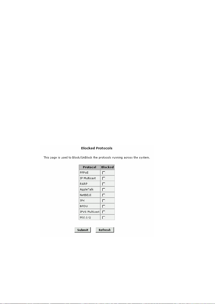
4.15 Blocked Protocols
Click the Blocked Protocols of Advanced Function in the
Wizard Column to set the Blocked Protocols. The MT800 is capable
of sending and receiving information in a variety of protocol formats.
The Blocked Protocols feature enables you to prevent the MT800
from passing any data that uses a particular protocol. Unlike the IP
Filter feature, you cannot specify additional criteria for blocked
protocols, such as particular users or destinations. However, when
you are certain that a particular protocol is not needed or wanted on
your network, this feature provides a convenient way to discard such
data before it is passed.
I.
Configuration page
Figure 4-32 Blocked protocols
To block a protocol, click the appropriate check box.
66
Page 77

II.
Save
Click the Submit button to save the settings in the RAM.
z
To save these configuration changes permanently, enter
z
the Save & Reboot page, select Save and click Submit
button to save new settings.
4.16 Diagnostics
The diagnostics feature executes a series of test of your system
software and hardware connections. Use this feature when working
with your ISP to solve problems. Click the Diagnostics of Advance
Function in the Wizard column to perform the basic diagnostics for
system.
Figure 4-33 Diagnostics window
67
Page 78

Select the Virtual Circuit and click the Submit button. A
message will appear, informing you whether the loop test succeeded
or failed.
The diagnostics utility will run a series of test to check whether
the device's connections are up and working. This takes only a few
seconds. The program reports whether the test passed or failed. A
test may be skipped if the program determines that no suitable
interface is configured on which to run the test.
4.17 Access Management
4.17.1 User Management
The first time you log into the Web Configuration Manager, use
the default user ID and password (admin and admin).
Figure 4-34 Access management
I.
Change the password
For the default user ID, admin, only the password can be
changed. The method to change the password of admin or users is
described as below:
68
Page 79

Figure 4-35 User Config-Modify
Perform the following steps to change the password:
2) Open the Access Management page;
3) Enter the configuration page User Config-Modify by click
in the operation column;
the
4) Enter the new password, confirm the password and
submit.
Save the setting in the Save & Reboot page and then restart
the system to take effect the setting.
Note:
It is recommended to keep a record of the new password after modified.
69
Page 80

II.
Add new user
To add new user ID and password, click the Add Button in
Access Management page, log into the User Configuration-Add
page.
Figure 4-36 User config - add
User ID: This lists the current User ID (user name).
z
Privilege:
z
Root – can access and modify system configurations
User – can read limited configurations.
Password: Type in the new password.
z
Confirm Password: Type in the new password a second
z
time for confirmation.
If you need to delete a user, click the icon
column that the user located to delete the user.
70
in the operation
Page 81

4.17.2 Web Management
Please input the value of Inactivity TimeOut duration in minutes.
If the idle time of web-based management exceeds the input time,
the web management will be closed. To access the web
management page, you should login again.
Figure 4-37 Web management
Enter a value of inactivity timeout in the blank and then click
Submit button. The default value is “0”.
4.17.3 ILMI
ILMI (Interim Local Management Interface) allow user to set an
interface, which to be activated while the existing ATM interfaces is
toggling or temporarily failed.
71
Page 82

Figure 4-38 Ilmi
Ilmi: Select to enable or disable the Ilmi mode.
z
VPI: If you need any modification, please enter the VPI
z
value of Ilmi that provided by ISP.
VCI: If you need any modification, please enter the VCI
z
value of Ilmi that provided by ISP.
4.17.4 ACL
Access Control List is used to allow or deny the access from one
or more specific IP addresses in LAN and WAN.
72
Page 83

I.
Configuration page
Figure 4-39 Access control list
II.
Parameter explanation
ACL: Select to allow or deny the access LAN interface or
z
WAN interface.
Add IP Address (max 5): Type in the IP address for the
z
LAN interface or WAN interface. The maximum number of
IP address can be entered is 5.
Click the Status button in the access control list to view the ACL
statistics of relative IP address. If you need to modify an IP address,
click icon
III.
z
, click the icon to delete an IP address.
Save
Click the Submit button to save the settings in the RAM.
73
Page 84

To save these configuration changes permanently, enter
z
the Save & Reboot page, select Save and click Submit
button to save new settings.
4.18 Statistics
MT800 provides the statistic figures for DSL and ATM/LAN.
4.18.1 DSL
Click the DSL of Statistics in the Wizard Column to view the log
of device.
Figure 4-40 DSL status
74
Page 85

Choose from the pull-down menu to set the refresh rate in
seconds. The larger the value is, the slower the refresh rate is.
4.18.2 ATM/LAN
The device keeps statistic of the data traffic that it handles. You
are able to read the amount of Receive and Transmit packets that
pass through the device on both the ATM port and the LAN (Local
Area Network) ports.
Figure 4-41 ATM/LAN
Select PVC number from the pull-down menu to view the details
of traffic statistics, Click the Refresh button to update the counters
and the Refresh button to clear the counters.
75
Page 86

4.19 Save & Reboot
Click the Save & Reboot in Wizard column to specify the
method of restart.
I.
Configuration page
Figure 4-42 Save & Reboot
II.
Parameter explanation
Save: Save the current setting into the permanent storage
z
Reboot: A simple reboot: This will put into effect any
z
configuration changes that have been successfully saved
to flash memory.
Factory Setting Reboot: This reboots the device to
z
default settings provided by your ISP or the manufacturer.
Choosing this option erases any custom settings.
You should select the proper method to restart the system.
76
Page 87

Caution:
Do not reboot the device using the Reset button on the back panel of the MT800 to
activate new changes. This button resets the device settings to the manufacturer’s
default values. Any custom settings will be lost.
4.20 Firmware Upgrade
Click the hyperlink Firmware Upgrade in the Wizard column to
open the Firmware Upgrade page and update the system software.
Figure 4-43 Firmware upgrade
Upgrade File: Type in the full path and file name of the firmware
file to be uploaded. Alternatively you may click the Browse button to
search for the file on your system.
When the file names have been entered, click the Upload
button to start loading the firmware file. If the upload is successful, a
message informs you that it was successfully loaded. If the firmware
does not load, an error message informs you to try the upload again.
Check the file names and attempt to upload again. If the file still is not
loaded, reboot the device and try again.
77
Page 88

Caution:
Do not power off the MT800 during the firmware upgrade process. Otherwise, the
configuration in the flash could be damaged.
4.21 Alarm
Figure 4-44 Alarm
You can view the logs of alarm in response to system events.
Select Refresh rate from the drop-down menu. Click the Save Alarm
button to save the log file to local disk. Click the Clear button to clear
the logs and Refresh button to view the recent alarm events.
78
Page 89

Chapter 5 Service Configuration
This section describes the configuration for six modes of
SmartAX MT800 ADSL router device for ADSL online service. The
contents include:
Preparation for service configuration
z
PPPoE
z
PPPoA
z
RFC 2684 Bridged (Pure Bridge)
z
RFC 2684 Bridged (Static IP)
z
RFC 2684 Bridged (DHCP)
z
RFC 2684 Route (IPoA)
z
5.1 Preparation for Service Configuration
Collect the following data firstly to perform the configuration:
79
Page 90

Protocol
types
Preparing
informati
on
Virtual dialup
mode
RFC
2648
PPPoE PPPoA
Connec
tion
Type
PPPoE
user
name
PPPoE
passwo
rd
VPI/VCI VPI/VCI None
Securit
y
Protoco
l
Connecti
on Type
PPPoA
user
name
PPPoA
passwor
d
Security
Protocol
Bridged
(Pure
Bridge)
Connecti
on Type
VPI/VCI VPI/VCI VPI/VCI VPI/VCI
None WAN IP None WAN IP
None
DSL mode
RFC
2684
Bridged
(Static
IP)
Connecti
on Type
Subnet
mask
Default
gateway
RFC
2684
Bridged
(DHCP)
Connec
tion
Type
None
None
RFC
2684
Route
(IPoA)
Connec
tion
Type
Subnet
mask
Default
gatewa
y
None None None DNS DNS DNS
5.2 PPPoE Configuration
Configurations on MT800
Location Parameters Comments
PVC Select any one from the eight PVCs. ATM Setting
VPI/VCI The value shall be provided by your ISP.
80
Page 91

Configurations on MT800
Location Parameters Comments
Operation Mode Select “Enable”.
The value shall be provided by your ISP.
Encapsulation
Usually you can keep the default value:
LLC.
Connection Type Select “PPP”.
PPPoA/PPPoE Select “PPPoE”.
User name and
Password
The values shall be provided by your ISP.
Default Route Select “Enable”.
DNS Select “Enable”.
NAT It is recommended to enable the function of NAT.
DNS It is recommended to have DNS Relay function enabled.
DHCP Mode It is recommended to have DHCP Server function enabled.
Traffic Index It is recommended to set 0.
Configurations on the user’s PC
IP Address and
Network Mask
It is recommended to set the mode as obtaining an IP address
automatically.
DNS
It is recommended to set the mode as obtaining a DNS server’s
IP address automatically.
81
Page 92

5.3 PPPoA Configuration
Configurations on MT800
Location Parameters Comments
PVC Select any one from the eight PVCs.
VPI/VCI The value shall be provided by your ISP.
Operation Mode Select “Enable”.
The value shall be provided by your ISP.
Usually you can keep the default value:
LLC.
ATM Setting
Encapsulation
Connection Type Select “PPP”.
PPPoA/PPPoE Select “PPPoA”.
User name and
Password
Default Route Select “Enable”.
DNS Select “Enable”.
NAT It is recommended to enable the function of NAT.
DNS It is recommended to have DNS Relay function enabled.
DHCP Mode It is recommended to have DHCP Server function enabled.
Traffic Index It is recommended to set 0.
Configurations on the user’s PC
IP Address and
Network Mask
DNS
It is recommended to set the mode as obtaining an IP address
automatically.
It is recommended to set the mode as obtaining a DNS server’s
IP address automatically.
The values shall be provided by your ISP.
82
Page 93

5.4 RFC 2684 Bridged (Pure Bridge)
Configuration
Configurations on MT800
Location Parameters Comments
PVC Select any one from the eight PVCs.
VPI/VCI The value shall be provided by your ISP.
Operation Mode Select “Enable”.
ATM Setting
Encapsulation
Connection Type Select “RFC2684 Bridged”.
Address Type Select “Pure Bridge”.
Traffic Index It is recommended to set 0.
Configurations on the user’s PC
PPPoE Dial–up
Application
Before connecting to the Internet, the user shall have PPPoE
dial–up application installed on the PC.
The value shall be provided by your ISP.
Usually you can keep the default value:
LLC.
5.5 RFC 2684 Bridged (Static IP) Configuration
Configurations on MT800
Location Parameters Comments
ATM Setting
PVC Select any one from the eight PVCs.
VPI/VCI The value shall be provided by your ISP.
Operation Mode Select “Enable”.
83
Page 94

Configurations on MT800
Location Parameters Comments
Encapsulation
The value shall be provided by your ISP.
Usually you can keep the default value:
LLC.
Connection Type Select “RFC2684 Bridged”.
Address Type Select “Static IP”.
IP Address and
Subnet Mast
The values shall be provided by your ISP.
Default Route Select “Enable”.
ATM Setting
Gateway IP
Address
The value shall be provided by your ISP.
NAT It is recommended to enable the function of NAT.
It is recommended to have DNS Relay function enabled.
DNS
And set DNS IP address provided by your ISP.
DHCP Mode It is recommended to have DHCP Server function enabled.
Traffic Index It is recommended to set 0.
Configurations on the user’s PC
IP Address and
Network Mask
It is recommended to set the mode as obtaining an IP address
automatically.
DNS
It is recommended to set the mode as obtaining a DNS server’s
IP address automatically.
84
Page 95

5.6 RFC 2684 Bridged (DHCP) Configuration
Configurations on MT800
Location Parameters Comments
PVC Select any one from the eight PVCs.
VPI/VCI The value shall be provided by your ISP.
Operation Mode Select “Enable”.
The value shall be provided by your ISP.
Encapsulation
ATM Setting
Connection Type Select “RFC2684 Bridged”.
Address Type Select “DHCP”.
Default Route Select “Enable”.
Usually you can keep the default value:
LLC.
Gateway IP
Address
NAT It is recommended to enable the function of NAT.
DNS
DHCP Mode It is recommended to have DHCP Server function enabled.
Traffic Index It is recommended to set 0.
IP Address and
Network Mask
DNS
It is recommended to have DNS Relay function enabled.
And set DNS IP address provided by your ISP.
Configurations on the user’s PC
It is recommended to set the mode as obtaining an IP address
automatically.
It is recommended to set the mode as obtaining a DNS server’s
IP address automatically.
The value shall be provided by your ISP.
85
Page 96

5.7 RFC 2684 Route (IPoA) Configuration
Configurations on MT800
Location Parameters Comments
PVC Select any one from the eight PVCs.
VPI/VCI The value shall be provided by your ISP.
Operation Mode Select “Enable”.
The value shall be provided by your ISP.
Encapsulation
ATM Setting
Connection Type Select “RFC2684 Routed (IPoA)”.
Usually you can keep the default value:
LLC.
IP Address and
Subnet Mast
Default Route Select “Enable”.
Gateway IP
Address
NAT It is recommended to enable the function of NAT.
DNS
DHCP Mode It is recommended to have DHCP Server function enabled.
Traffic Index It is recommended to set 0.
IP Address and
network mask
DNS
It is recommended to have DNS Relay function enabled.
And set DNS IP address provided by your ISP.
Configurations on the user’s PC
It is recommended to set the mode as obtaining an IP address
automatically.
It is recommended to set the mode as obtaining a DNS server’s
IP address automatically.
The values shall be provided by your ISP.
The value shall be provided by your ISP.
86
Page 97

Note:
For other advanced configurations, please refer to Chapter 4 Web-based
Management.
87
Page 98

Chapter 6 Troubleshooting
6.1 Quick Troubleshooting
Failures Instructions
Power light is
out.
ADSL LINK
light is out.
LAN LINK
light is out.
1. Ensure power adapter is well connected;
2. Ensure the right power adapter is used.
1. Ensure the ADSL line is well connected;
2. Ensure the telephone line before entering the house is
valid, try to test with a telephone;
3. Check that there is no junction box before connecting
MT800, which has such components like capacitors or
diodes that could hinder back high frequency signals;
4. Ensure the MT800 and telephones are connected in the
right way.
1. Ensure you use the right cables from the MT800 to your PC;
2. Ensure the connection is secured;
3. Check if the NIC LED lights up;
4. Ensure your Network Adapter works normally by examining
whether the item of “Networking Adapters” is labeled with
“?” or “!”. If it is, you may delete it and then click “Refresh”
to reinstall. Otherwise, you may try the NIC in another slot.
As a last resort, you have to replace the NIC.
88
Page 99

Failures Instructions
Take the most common access mode as an example, in which a
dial-up application is installed on the user’s computer:
1. Ensure that any of the problems above is not the reason;
2. Ensure that the dial-up application is correctly installed and
set on your PC;
Can’t access
the Internet.
3. Ensure that you have entered the right user name and
password;
4. Ensure “Use Proxy Server” is set properly for IE, if the
problem still remains even after you have log into
successfully;
5. Try more than one Web sites, in case of some Web server’s
being in failure.
6.2 FAQs
Q: Why can’t my computer access the Internet, even when
the physical links are well connected?
Check first whether the LEDs are in normal status. If they do,
you have to find help to adjust the settings on the MT800.
Q: I forget the username and password when I am to log
into the Web-based Configuration Manager. Or I just can’t
access the Web-based Configuration Manager.
1) Please press reset button at the rear panel for 3 seconds to
restore the factory default settings of MT800.
2) Indicate your NIC IP address to 192.168.1.3
3) Disable Proxy service.
4) Launch your Web browser and type in http://192.168.1.1
89
Page 100

5) Use the default user name: admin and password: admin
Q: My configuration is gone after rebooting MT800.
If you want to keep your settings after reboot MT800. Please go
to Web-based Configuration Manager Æ “Save & Reboot” Æ “Save”
to save your configurations.
Figure 6-1 Save the changed setting
Q: I can’t upgrade with the new firmware.
Please make sure the file that you have downloaded is valid.
Q: Why can’t I access the Internet by using virtual dialing
through Microsoft’s Internet Gateway?
Internet Gateway supports PPPoE itself. No other PPPoE
terminal software shall be installed again.
Q: Why does my PC fall off line sometimes even with all
LEDs are in normal status?
There are several scenarios might cause this problem.
6) Be disconnected by the ISP.
7) Some ISPs will have idle timeout setting to avoid wasting
IP. When the end user connects to the Internet too long
90
 Loading...