

Page 1
IDS1000 Container Data Center
Single-Zone Fire Extinguishing System
User Manual
Issue
01
Date
2014-3-15
HUAWEI TECHNOLOGIES CO., LTD.
Page 2

Issue 01 (2014-3-15)
Huawei Proprietary and Confidential
Copyright © Huawei Technologies Co., Ltd.
i
Copyright © Huawei Technologies Co., Ltd. 2014. All rights reserved.
No part of this document may be reproduced or transmitted in any form or by any means without prior
written consent of Huawei Technologies Co., Ltd.
Trademarks and Permissions
and other Huawei trademarks are trademarks of Huawei Technologies Co., Ltd.
All other trademarks and trade names mentioned in this document are the property of their respective
holders.
Notice
The purchased products, services and features are stipulated by the contract made between Huawei and
the customer. All or part of the products, services and features described in this document may not be
within the purchase scope or the usage scope. Unless otherwise specified in the contract, all statements,
information, and recommendations in this document are provided "AS IS" without warranties, guarantees or
representations of any kind, either express or implied.
The information in this document is subject to change without notice. Every effort has been made in the
preparation of this document to ensure accuracy of the contents, but all statements, information, and
recommendations in this document do not constitute a warranty of any kind, express or implied.
Huawei Technologies Co., Ltd.
Address:
Huawei Industrial Base
Bantian, Longgang
Shenzhen 518129
People's Republic of China
Website:
http://www.huawei.com
Email:
support@huawei.com
Page 3
IDS1000 Container Data Center
User Manual
About This Document
Issue 01 (2014-3-15)
Huawei Proprietary and Confidential
Copyright © Huawei Technologies Co., Ltd.
ii
Purpose
Symbol
Description
Indicates an imminently hazardous situation which, if
not avoided, will result in death or serious injury.
Indicates a potentially hazardous situation which, if not
avoided, could result in death or serious injury.
Indicates a potentially hazardous situation which, if not
avoided, may result in minor or moderate injury.
Indicates a potentially hazardous situation which, if not
avoided, could result in equipment damage, data loss,
performance deterioration, or unanticipated results.
NOTICE is used to address practices not related to
This document describes the operation methods and precautions for the fire extinguishing
system in the IDS1000 container data center in terms of configurations, power-on
commissioning, maintenance, alarm references, troubleshooting, and parts replacement. It
provides you a quick grasp of the operations of the fire extinguishing system in the container
data center.
Intended Audience
About This Document
This document is intended for:
Maintenance engineers
Technical support engineers
System engineers
Hardware installation engineers
Commissioning engineers
Symbol Conventions
The symbols that may be found in this document are defined as follows.
Page 4

IDS1000 Container Data Center
User Manual
About This Document
Issue 01 (2014-3-15)
Huawei Proprietary and Confidential
Copyright © Huawei Technologies Co., Ltd.
iii
Symbol
Description
personal injury.
Calls attention to important information, best practices
and tips.
NOTE is used to address information not related to
personal injury, equipment damage, and environment
deterioration.
Change History
Changes between document issues are cumulative. The latest document issue contains all the
changes made in earlier issues.
Issue 01 (2014-03-15)
This issue is the first official release.
Page 5

IDS1000 Container Data Center
User Manual
Contents
Issue 01 (2014-3-15)
Huawei Proprietary and Confidential
Copyright © Huawei Technologies Co., Ltd.
iv
Contents
About This Document .................................................................................................................... ii
1 Configuration Description .......................................................................................................... 1
1.1 System Introduction ...................................................................................................................................................... 1
1.2 Components .................................................................................................................................................................. 4
1.3 Configuration Principles ............................................................................................................................................... 6
2 Operation Description ................................................................................................................. 8
2.1 Precautions .................................................................................................................................................................... 8
2.2 Emergency Operation Overview ................................................................................................................................... 8
2.3 Preparations .................................................................................................................................................................. 9
2.3.1 Obtaining Tools .......................................................................................................................................................... 9
2.3.2 Obtaining Technical Documents .............................................................................................................................. 10
2.3.3 Personnel Skill Requirements .................................................................................................................................. 11
3 Power-On Commissioning ........................................................................................................ 12
3.1 Initial Configuration ................................................................................................................................................... 12
3.2 Checking Before Power-On ........................................................................................................................................ 17
3.3 Hardware Power-On Commissioning ......................................................................................................................... 19
3.4 Fire Extinguishing System Commissioning ................................................................................................................ 20
4 Routine Maintenance ................................................................................................................. 29
4.1 Routine Maintenance Overview ................................................................................................................................. 29
4.2 Daily Maintenance ...................................................................................................................................................... 29
4.3 Weekly Maintenance ................................................................................................................................................... 30
4.4 Monthly Maintenance ................................................................................................................................................. 30
4.5 Quarterly Maintenance ............................................................................................................................................... 31
4.6 Semi-Yearly Maintenance ........................................................................................................................................... 32
4.7 Yearly Maintenance .................................................................................................................................................... 33
5 Alarm Reference .......................................................................................................................... 34
6 Troubleshooting .......................................................................................................................... 36
6.1 Smoke Detector Fault ................................................................................................................................................. 36
6.2 Heat Detector Fault ..................................................................................................................................................... 37
6.3 Gas Release Indicator Fault ........................................................................................................................................ 39
Page 6

IDS1000 Container Data Center
User Manual
Contents
Issue 01 (2014-3-15)
Huawei Proprietary and Confidential
Copyright © Huawei Technologies Co., Ltd.
v
6.4 Audible and Visual Alarm Fault .................................................................................................................................. 40
6.5 Fire Alarm Bell Fault .................................................................................................................................................. 42
6.6 Failed to Drive the Fire Cylinder ................................................................................................................................ 43
6.7 VESDA Fault .............................................................................................................................................................. 43
6.8 Gas Extinguishing Controller Fault ............................................................................................................................ 43
7 Parts Replacement ....................................................................................................................... 45
7.1 Replacing a Smoke Detector ....................................................................................................................................... 45
7.2 Replacing a Heat Detector .......................................................................................................................................... 47
7.3 Replacing a Gas Release Indicator ............................................................................................................................. 49
7.4 Replacing an Audible and Visual Alarm ..................................................................................................................... 50
7.5 Replacing a Fire Alarm Bell ....................................................................................................................................... 51
7.6 Replacing a Fire Cylinder ........................................................................................................................................... 52
7.7 Replacing a Gas Extinguisher ..................................................................................................................................... 52
7.8 Replacing the Emergency Start/Abort Switch ............................................................................................................ 53
7.9 Replacing a VESDA ................................................................................................................................................... 54
7.10 Replacing a Gas Extinguishing Controller................................................................................................................ 55
8 Emergency Operation ................................................................................................................. 56
8.1 Early Fire Alarm ......................................................................................................................................................... 56
8.2 Single Fire Alarm ........................................................................................................................................................ 58
8.3 Composite Fire Alarm ................................................................................................................................................. 59
A Acronyms and Abbreviations .................................................................................................. 61
Page 7

IDS1000 Container Data Center
User Manual
1 Configuration Description
Issue 01 (2014-3-15)
Huawei Proprietary and Confidential
Copyright © Huawei Technologies Co., Ltd.
1
1 Configuration Description
1.1 System Introduction
System Composition
The container data center fire extinguishing system consists of the automatic fire alarm
system, gas extinguishing equipment, and the control system.
The automatic fire alarm system consists of components including the heat detector, smoke
detector, audible and visual alarm, alarm bell, gas release indicator, and the very early smoke
detection apparatus (VESDA for short, able to detect and report fire alarms at an early stage).
The gas extinguishing equipment uses heptafluropropane as the extinguishing agent. It
consists of components such as the extinguishing agent vessel, gas supply pipe, pressure
annunciator, and solenoid valve driver.
The control system consists of the gas extinguishing controller and emergency start/abort
switch.
Working Principles
When a fire occurs and generates smoke and heat, the smoke detector and the heat detector
will be triggered and send fire alarm signals to the fire controller. Then the controller will
generate a startup current to start the solenoid valve to open the storage valve, which will
release the extinguishing agent to the protected zone. The automatic alarm system will send
alarm signals at the same time.
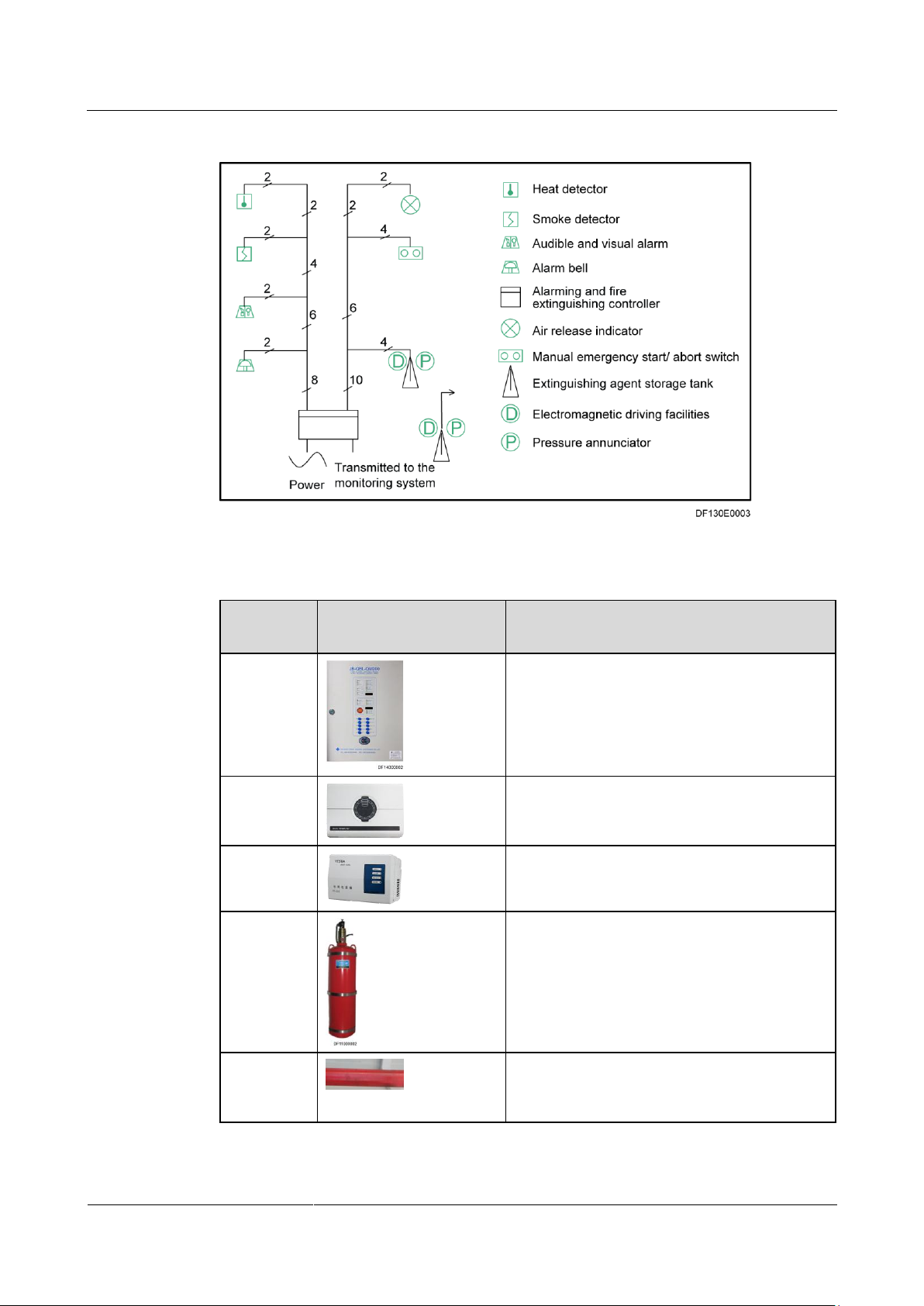
Figure 1-1 shows the network diagram of the container data center fire extinguishing system.
Table 1-1 lists the functions of the components in the fire extinguishing system.
Page 8
IDS1000 Container Data Center
User Manual
1 Configuration Description
Issue 01 (2014-3-15)
Huawei Proprietary and Confidential
Copyright © Huawei Technologies Co., Ltd.
2
Figure 1-1 Fire extinguishing system network diagram
Compone
nt Name
Appearance
Function
Gas
extinguishin
g controller
Controls the fire extinguishing system and
reports fire alarm signals.
VESDA
Detects smoke at an early stage, displays the
smoke density and alarm severities, and reports
these information to the monitoring system.
VESDA
power box
Supplies power to the VESDA.
Gas
extinguishin
g
equipment
Stores and releases an extinguishing agent.
Fire
extinguishin
g pipe
Transports an extinguishing agent swiftly and
evenly to the entire protected zone to
extinguish fire in total flooding mode.
Table 1-1 Functions of the components in the fire extinguishing system
Page 9
IDS1000 Container Data Center
User Manual
1 Configuration Description
Issue 01 (2014-3-15)
Huawei Proprietary and Confidential
Copyright © Huawei Technologies Co., Ltd.
3
Compone
nt Name
Appearance
Function
Atomizer
nozzle
Sprays an extinguishing agent to aisles in case
of a fire.
Gas release
indicator
Displays "DON'T ENTER WHILE
RELEASING GAS" to warn onsite personnel
in case of a fire and the fire extinguishing
equipment releases the extinguishing agent into
the protected zone.
Audible and
visual alarm
Generates dazzling flash signals and shrill
audible signals in case of a fire, reminding
onsite personnel to evacuate from the site
immediately, thereby avoiding major accident.
Emergency
start/abort
switch
Starts or stops the gas extinguishing equipment
in case of a fire. The device is installed outside
the door of the protected zone. If you press the
glass plate to start extinguishing in emergency,
the red indicator lights up.
Heat
detector
Evenly deployed in the aisles inside containers
to detect the temperature inside the containers
in real time. When it works in monitoring
mode, the red indicator blinks. When the
ambient temperature exceeds the alarm
threshold, it enters alarm mode and the red
indicator is steady on.
Smoke
detector
Evenly deployed in the aisles inside containers
to detect the smoke density inside the
containers in real time. When it works in
monitoring mode, the red indicator blinks.
When the onsite smoke density exceeds the
alarm threshold, it enters alarm mode and the
red indicator is steady on.
Alarm bell
Produces clear and consistent sounds in case of
a fire, reminding onsite personnel to evacuate
from the site immediately, thereby avoiding
major accident.
System Features
All surface-mounted fire control cables are routed through metal hoses. The hose ends
are protected with grommets to prevent damage in case of a fire. Fire control cables are
routed and used separately which ensures secure and reliable power supplies to the fire
extinguishing system.
Page 10
IDS1000 Container Data Center
User Manual
1 Configuration Description
Issue 01 (2014-3-15)
Huawei Proprietary and Confidential
Copyright © Huawei Technologies Co., Ltd.
4
Item
Specifications
AC input frequency
≤ 120 W
AC input voltage
220 V AC ± 20%
DC backup
power
Voltage
24 V DC
Electricity
7.0 Ah
Capacity
Number of detector
loops
Two loops: one loop connected to the common
heat detector and the other connected to the
smoke detector
Number of detectors
connected to each loop
≤ 20 (common detectors)
Wire system of the detector loop
Two-wire system
Length of the detector loop
≤ 1000 m
Relay contact capacity
7 A, 24 V DC for all relays
Each core component in the fire extinguishing system can be flexibly matched with each
other to create a system that meets the fire extinguishing requirements of different levels
in a single container or combined containers.
1.2 Components
Gas Extinguishing Controller
A gas extinguishing controller provides the following functions:
Detects and reports composite fire alarm signals in dual loops. It can be connected to the
emergency startup button, which ensures that the system operation is under control in
case of an emergency or during onsite equipment maintenance.
Restarts automatically after a fault is rectified.
Provides a port for the gas release confirmation signal (reporting pressure values).
Generates single and composite fire alarms, drives gas release indicators and audible and
visual alarms, and controls alarm bells.
Provides an independent output port for the solenoid valve driver and supports 3 A, 24 V
solenoid valve (electric detonator) startup current.
Detects the open circuit fault of the input loop and the short circuit and open circuit of
the output loop (in active output mode).
Provides the intelligent monitoring, and overcharge and overdischarge protection for
standby batteries.
Adopts the low-power consumption design, and supports at least 48-hour consecutive
operation for the backup power.
Provides password lock protection for the keypad to prevent misoperations.
Table 1-2 lists the specifications for the gas extinguishing controller.
Table 1-2 Specifications for the gas extinguishing controller
Page 11
IDS1000 Container Data Center
User Manual
1 Configuration Description
Issue 01 (2014-3-15)
Huawei Proprietary and Confidential
Copyright © Huawei Technologies Co., Ltd.
5
Item
Specifications
Solenoid valve output loop
≤ 3 A
Output loop current limit for other drivers
≤ 1 A
Item
Specifications
Dimensions
Outer diameter of the steel vessel: 364 mm
Maximum operating pressure
50°C: 3.4 MPa
Storage pressure
20°C: 4.2 MPa
Storage container volume
70 L
Heptafluropropane filling density
≤ 1120 kg/m3
Startup current
1.2 A
Startup voltage
24 V DC
Gas Extinguishing Equipment
The gas extinguishing equipment uses heptafluropropane as the extinguishing agent. It
consists of components such as the extinguishing agent vessel, gas supply pipe, pressure
annunciator, and solenoid valve driver.
Table 1-3 lists the specifications for the gas extinguishing equipment.
Table 1-3 Specifications for the heptafluropropane gas extinguishing equipment
VESDA
A VESDA consists of the host, power box, and sampling pipe. The VESDA host includes two
types: VLS and VLP. The VLS is a four-pipe scanning detector that can monitor each pipe and
generate alarms. The VLP is a standard detector that can only conduct general monitoring but
not for each pipe. The host should be configured based on practical requirements.
The detector host consists of a suction pump, filter, high-sensitivity smoke detector, and
precision electrical analyzer. The fan sucks air samples from the monitored environment
through the air sampling pipe to the smoke detector, which will analyze and process the
samples and calculate the amount of smoke in the air. If the smoke density exceeds the preset
alarm threshold, the system blinks and sends alarm signals to the ECC.
A dedicated PPS-004 power box should be configured for the VESDA. The PPS-004 power
box should be supplied by a 220 V AC main input and supplies 24 V DC power to the
VESDA host. Backup batteries should be deployed for the PPS-004 power box.
The features of the VESDA are as follows:
High sensitivity and wide sensitivity adjustment range (0.005–20% obs/m), able to detect
regular fires at an early stage as well as the particles generated by the softened insulation
layer of an overloaded power cable
Page 12
IDS1000 Container Data Center
User Manual
1 Configuration Description
Issue 01 (2014-3-15)
Huawei Proprietary and Confidential
Copyright © Huawei Technologies Co., Ltd.
6
Item
Specifications
Dimensions (H x W x D)
175 mm x 90 mm x 245 mm
Power supply voltage
24 V DC, powered by a dedicated power box (The
power box is powered by 220 V external AC input.)
Power backup duration
DC, 24 V, 7 Ah, ≥ 8 h
Temperature of the sampled air
0–40°C
IP level
IP30
Maintenance port
Real-time fault detector, air filter, and programming
port
Coverage area
500 m2
Component Name
Configuration Principle
Gas extinguishing
controller
Configure one single-zone gas extinguishing controller for each
single-zone fire extinguishing system.
Active air sampling which uses the high-efficient air suction pump to continuously suck
the air samples from the protected zone to the detection cell; detecting results less
influenced by air flow compared with the traditional fire detection method
Small-sized and easy for installation; able to be deployed based on onsite requirements,
adopting polyvinyl chloride (PVC) pipes that enable flexible installation such as on the
ceiling, under the floor, at the air conditioner air return vents, and in the positions that
require special protection, for example, inside the equipment cabinet through the
capillary air sampling pipes to monitor the equipment in the cabinet.
Using a dedicated filter to process the air that will be used to clean the laser measuring
cell, which prolongs the life span of the detector. The filter can be easily maintained and
replaced, and cleaned by blowing the air sampling pipe. Therefore, you do not have to
replace other components.
Improved self-diagnostic system that enables the monitoring of the VESDA system,
network, and sampling pipe status in real-time; generating alarm signals and able to
locate the faulty areas if a fault occurs
Table 1-4 lists the specifications for the VESDA.
Table 1-4 VESDA specifications
1.3 Configuration Principles
Each independent protected zone in the container data center can be configured with one
single-zone fire extinguishing system, as described in 1.1 System Introduction. Table 1-5
describes the quantity configuration principle for each component in the fire extinguishing
system.
Table 1-5 Quantity configuration principle for each component in the fire extinguishing system
Page 13
IDS1000 Container Data Center
User Manual
1 Configuration Description
Issue 01 (2014-3-15)
Huawei Proprietary and Confidential
Copyright © Huawei Technologies Co., Ltd.
7
Component Name
Configuration Principle
VESDA
Determine the model and quantity of VESDAs based on the size
of the protected zone.
VESDA power box
Determine the quantity of VESDA power boxes based on the
quantity of VESDAs. Each VESDA is configured with one power
box.
Gas extinguishing
equipment
Determine the quantity of gas extinguishing equipment based on
the size of the protected zone.
Fire extinguishing
pipe
After ensuring that extinguishing agents can be transported to the
entire protected zone swiftly and evenly, deploy the pipes flexibly
based on the layout of the protected zone.
Atomizer nozzle
Installed on fire extinguishing pipes based on the size of the
protected zone.
Gas release indicator
Configured at the entrance or exit of the protected zone (one to
two in general).
Audible and visual
alarm
Configured based on the size of the protected zone (one to two in
general).
Emergency start/abort
switch
Configured at the entrance or exit of the protected zone (one in
general).
Heat detector
Configured in couple with a smoke detector based on the size of
the protected zone.
Smoke detector
Configured in couple with a heat detector based on the size of the
protected zone.
Alarm bell
Configured based on the size of the protected zone (one to two in
general).
For details about how to configure the container data center fire extinguishing system, see
the corresponding descriptions in the Container Data Center Initial Configuration Guide.
A VESDA is optional in the fire extinguishing system. If it is not configured in the
practical solution, ignore the relevant VESDA descriptions in this document.
A gas extinguisher is an auxiliary device in the fire extinguishing system. If it is not
configured in the practical solution, ignore the relevant gas extinguishing equipment
descriptions in this document.
Page 14

IDS1000 Container Data Center
User Manual
2 Operation Description
Issue 01 (2014-3-15)
Huawei Proprietary and Confidential
Copyright © Huawei Technologies Co., Ltd.
8
2.1 Precautions
Before commissioning the fire extinguishing system, ensure that all control cables to fire
cylinder solenoid valves have been disconnected. This prevents the fire extinguishing
equipment from malfunctioning due to improper manual operations or incorrect cable
connections, and further prevents accidental damage. After the commissioning is
complete, reconnect the solenoid valves.
To ensure the normal operation of the fire extinguishing system, the dowel tightening the
solenoid valve and the container valve must be removed. To prevent the fire
extinguishing system from spraying falsely when installing the IT equipment and
commissioning the system, remove the dowel tightening the solenoid valve and the
container valve on the fire cylinder only after you have commissioned the IT equipment
and fire extinguishing system.
Before commissioning the system, perform the jumper operation for the passive output.
Otherwise, the 6 A fuse (5D) on the main board will be damaged.
The main task involves commissioning of fire extinguishing association, which can be
operated only by professionals in this field.
Only qualified personnel are allowed to perform the operation and maintenance (O&M)
on the fire extinguishing system of the container data center.
Before performing routine maintenance of the fire extinguishing system, inform the
related departments of the temporary downtime due to maintenance. In addition, disable
the logical control function of the area or system to prevent false alarms. Inform the
related departments of the system recovery after the maintenance is complete.
Take ESD measures before removing the front panel from the VESDA.
The following contents in this document describe the operation of a single-zone fire
extinguishing system. If the container data center is configured with multiple single-zone
fire extinguishing systems, perform the operation based on corresponding introductions
in this document.
2 Operation Description
2.2 Emergency Operation Overview
Precautions
Only qualified personnel are allowed to perform emergency operations.
Page 15
IDS1000 Container Data Center
User Manual
2 Operation Description
Issue 01 (2014-3-15)
Huawei Proprietary and Confidential
Copyright © Huawei Technologies Co., Ltd.
9
Alarm or
Fault
Find Through
Possible
Causes
Possible
Impact
Emergency
Operation
Early fire alarm
System and
equipment
alarms or
maintenance
There is slight
smouldering in
the data center.
A fire is caused.
8.1 Early Fire
Alarm
Single fire
alarm
System and
equipment
alarms or
maintenance
A smoke alarm
or heat alarm is
generated.
A fire is caused.
8.2 Single Fire
Alarm
Composite fire
alarm
System and
equipment
alarms or
maintenance
A fire is caused
in the data
center.
The data center
is destroyed.
8.3 Composite
Fire Alarm
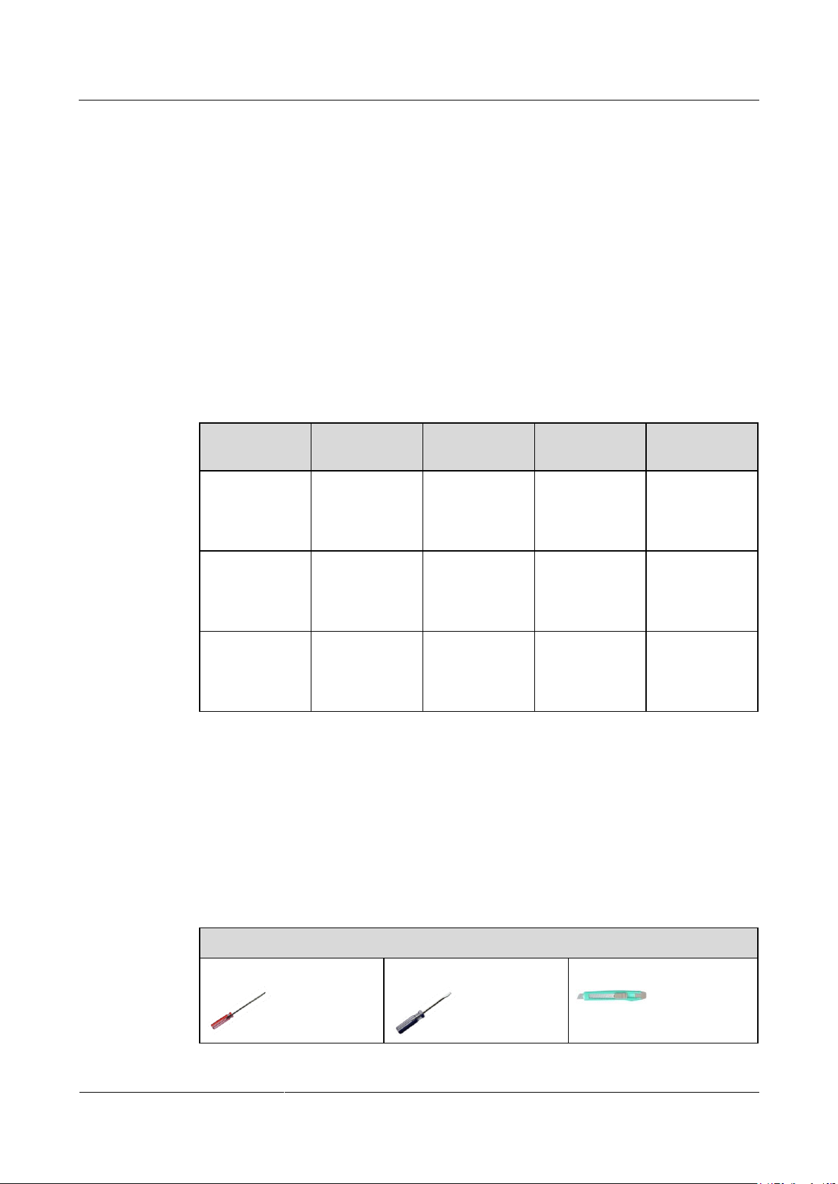
Tools and Materials
Phillips screwdriver
Flat-head screwdriver
Box cutter
Emergency operations are performed only when a critical alarm or fault occurs in the
container data center.
Emergency operations are basic measures taken to prevent or reduce the loss or
destruction of the container data center. When performing emergency operations during
the O&M process, also take the actual situation into consideration.
This document provides only common emergency operations for the container data
center. It does not cover all emergency operations. If the symptom is different from the
symptom described in this document, do not use the method provided in this document
to rectify the fault.
For more information about emergency operations, contact Huawei technical support.
Common Critical Alarms and Faults
Table 2-1 describes the common critical alarms and faults of the container data center.
Table 2-1 Common critical alarms and faults
2.3 Preparations
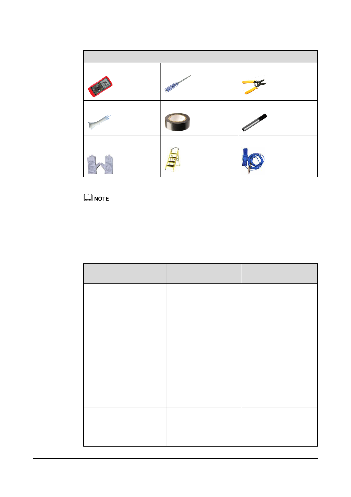
2.3.1 Obtaining Tools
Table 2-2 lists the tools required for the container data center.
Table 2-2 Tools and materials
Page 16
IDS1000 Container Data Center
User Manual
2 Operation Description
Issue 01 (2014-3-15)
Huawei Proprietary and Confidential
Copyright © Huawei Technologies Co., Ltd.
10
Tools and Materials
Multimeter
Electroprobe
Wire stripper
Cable ties
PVC insulation tape
Marker
Electrostatic discharge
(ESD) gloves
Ladder (2 m)
ESD wrist strap
Technical Manual
Function
Obtaining Method
(Remarks)
Container Data Center
Installation Parameter
Description
Provides guide for the
container data center initial
configurations. You can
obtain fire extinguishing
system initial
configurations and the
reported alarm information
in the management system.
Downloaded from
http://support.huawei.com.
Container Data Center
Power-On Commissioning
Guide
Provides guide for the
power-on commissioning,
and shutdown and
power-off for the container
data center. You can obtain
the power control
information of the fire
extinguishing system.
Downloaded from
http://support.huawei.com.
iManager NetEco 6000
Product Documentation
Provides guide for
installing, configuring, and
commissioning the
management system. You
can obtain the methods for
Downloaded from
http://support.huawei.com.
The listed tools are for routine maintenance only. Prepare other tools as required.
2.3.2 Obtaining Technical Documents
Table 2-3 lists the documents required for the operation and maintenance (O&M) of the
container data center fire extinguishing system.
Table 2-3 O&M document list
Page 17
IDS1000 Container Data Center
User Manual
2 Operation Description
Issue 01 (2014-3-15)
Huawei Proprietary and Confidential
Copyright © Huawei Technologies Co., Ltd.
11
Technical Manual
Function
Obtaining Method
(Remarks)
configuring the fire
extinguishing controller
and VESDA in the
management system.
Container Data Center
Installation Guide
Provides guide for
installing the container data
center. You can obtain the
methods for installing the
container data center
hardware devices.
Downloaded from
http://support.huawei.com.
Container Data Center O&M
Parameter Description
Provides guide for
operating and maintaining
the container data center.
You can obtain the
relationship between the
fire extinguishing system
and other systems in the
container data center.
Downloaded from
http://support.huawei.com.
Container Data Center Core
Component Document
Package
Provides guide for the
power-on commissioning,
configuration, and O&M of
core components.
Provided by Huawei for the
customer during project
delivery.
Field
Personnel Skill Requirement
Remarks
Fire
extinguishing
system
Familiar with the configurations of
the fire extinguishing system and
the operations of each core
component
Familiar with the overall
configurations and layout of the
container data center
Experienced in maintaining the fire
extinguishing system
None
2.3.3 Personnel Skill Requirements
Table 2-4 describes the skills required for the container data center fire extinguishing system
O&M personnel.
Table 2-4 Requirements for the O&M personnel
Page 18
IDS1000 Container Data Center
User Manual
3 Power-On Commissioning
Issue 01 (2014-3-15)
Huawei Proprietary and Confidential
Copyright © Huawei Technologies Co., Ltd.
12
3 Power-On Commissioning
3.1 Initial Configuration
Prerequisites
The container data center has been installed and passed installation tests.
You have obtained the Container Data Center Initial Configuration Guide for the
corresponding solution.
Procedure
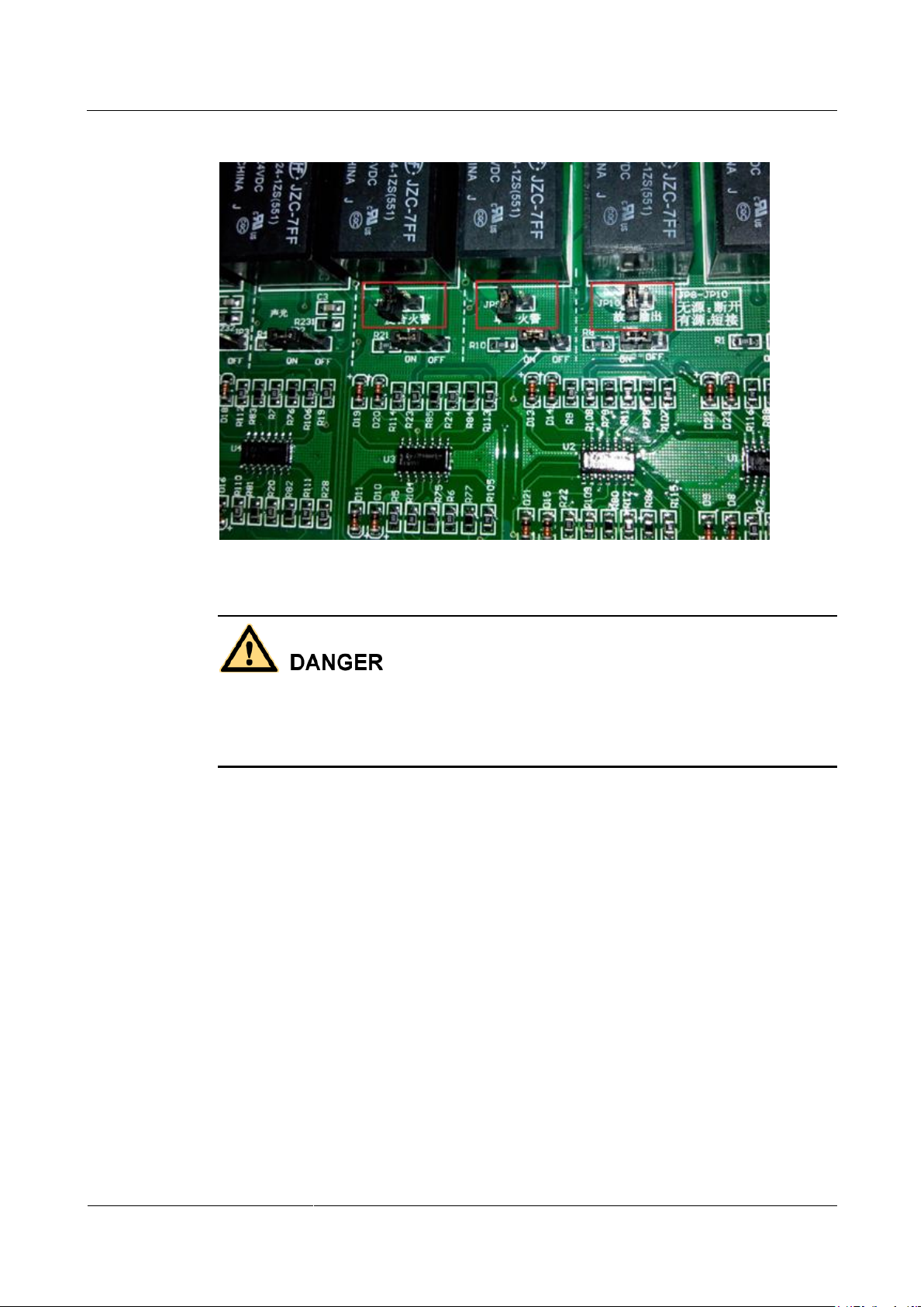
Step 1 Set the output jumper mode of the single alarm (JP8), composite alarm (JP9), and general
Before commissioning the fire extinguishing system, familiarize yourself with the
configurations of the fire extinguishing system and the layout of each component in the
corresponding solution. For details, see the Container Data Center Initial Configuration
Guide for corresponding solutions.
fault (JP10) to passive output, as shown in Figure 3-1.
Page 19
IDS1000 Container Data Center
User Manual
3 Power-On Commissioning
Issue 01 (2014-3-15)
Huawei Proprietary and Confidential
Copyright © Huawei Technologies Co., Ltd.
13
Figure 3-1 Setting passive output for alarms
You must perform the jumper operation. Otherwise, the 6 A fuse (5D) on the main board will
be damaged.
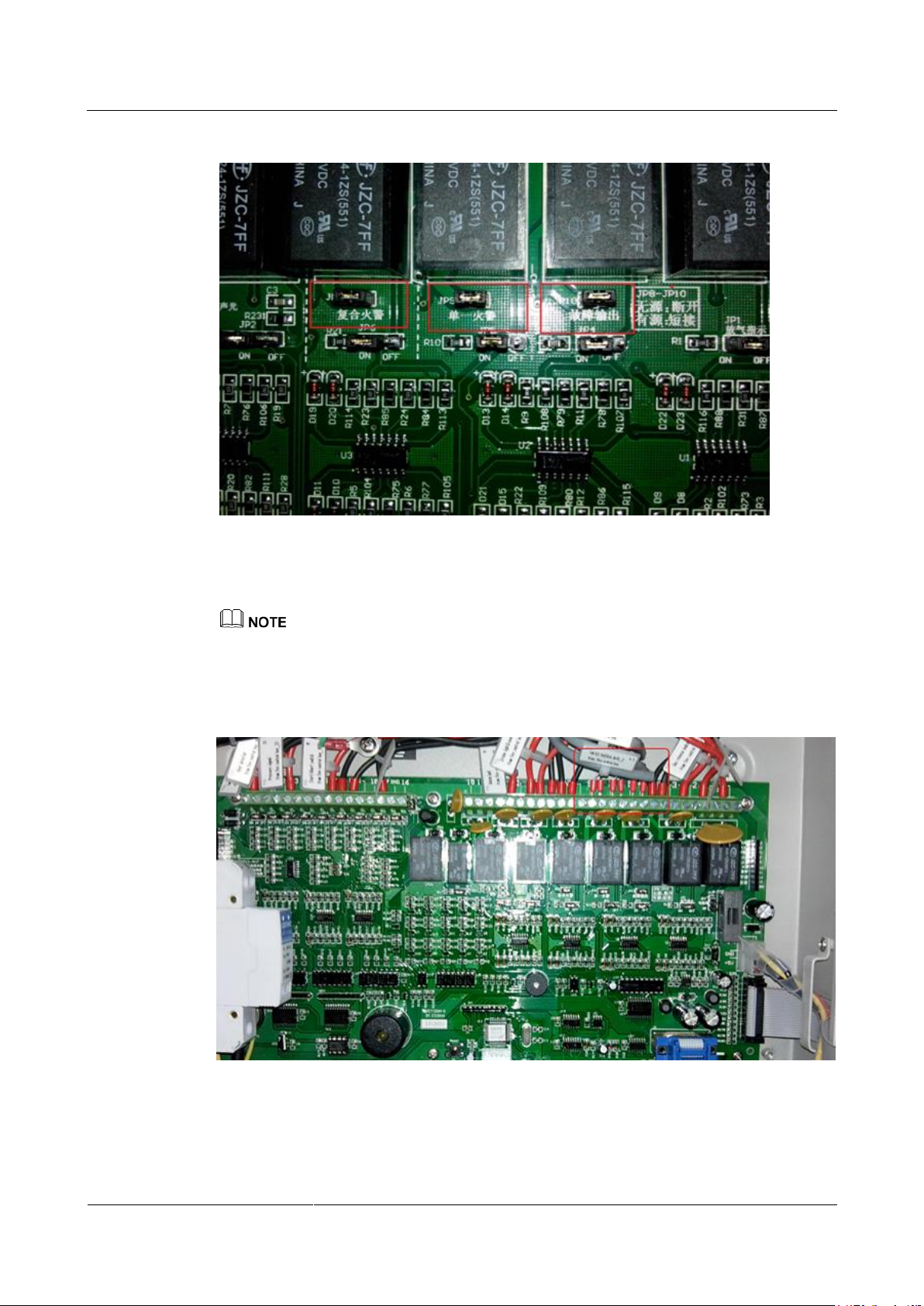
The factory setting of the jumper mode on the fire extinguishing controller for the single
alarm, composite alarm, and general fault is active output, as shown in Figure 3-2.
Page 20
IDS1000 Container Data Center
User Manual
3 Power-On Commissioning
Issue 01 (2014-3-15)
Huawei Proprietary and Confidential
Copyright © Huawei Technologies Co., Ltd.
14
Figure 3-2 Setting active output for alarms
Step 2 Check the connections of the monitoring cables for reporting the single alarm, composite
alarm, and general fault.
The gas extinguishing controller adopts the passive output to report the alarms, and reports alarm signals
to the management system through the network cable. Figure 3-3 shows the correct cable connections.
Figure 3-3 Correct cable connections for the general fault cables (4, 5), single alarm cables (6, 7),
and composite alarm cables (8, 9)
Step 3 Set the solenoid valve test mode.
Page 21
IDS1000 Container Data Center
User Manual
3 Power-On Commissioning
Issue 01 (2014-3-15)
Huawei Proprietary and Confidential
Copyright © Huawei Technologies Co., Ltd.
15
For details about how to set the solenoid valve test mode, see the Container Data Center
Initial Configuration Guide.
1. If the system is configured with one fire extinguishing cylinder and no fire extinguishing
power box is configured (fire extinguishing power module SJ-DYX-0607, with relays
and batteries). Ensure that the jumper state for JP7 is OFF (detecting faults). If the
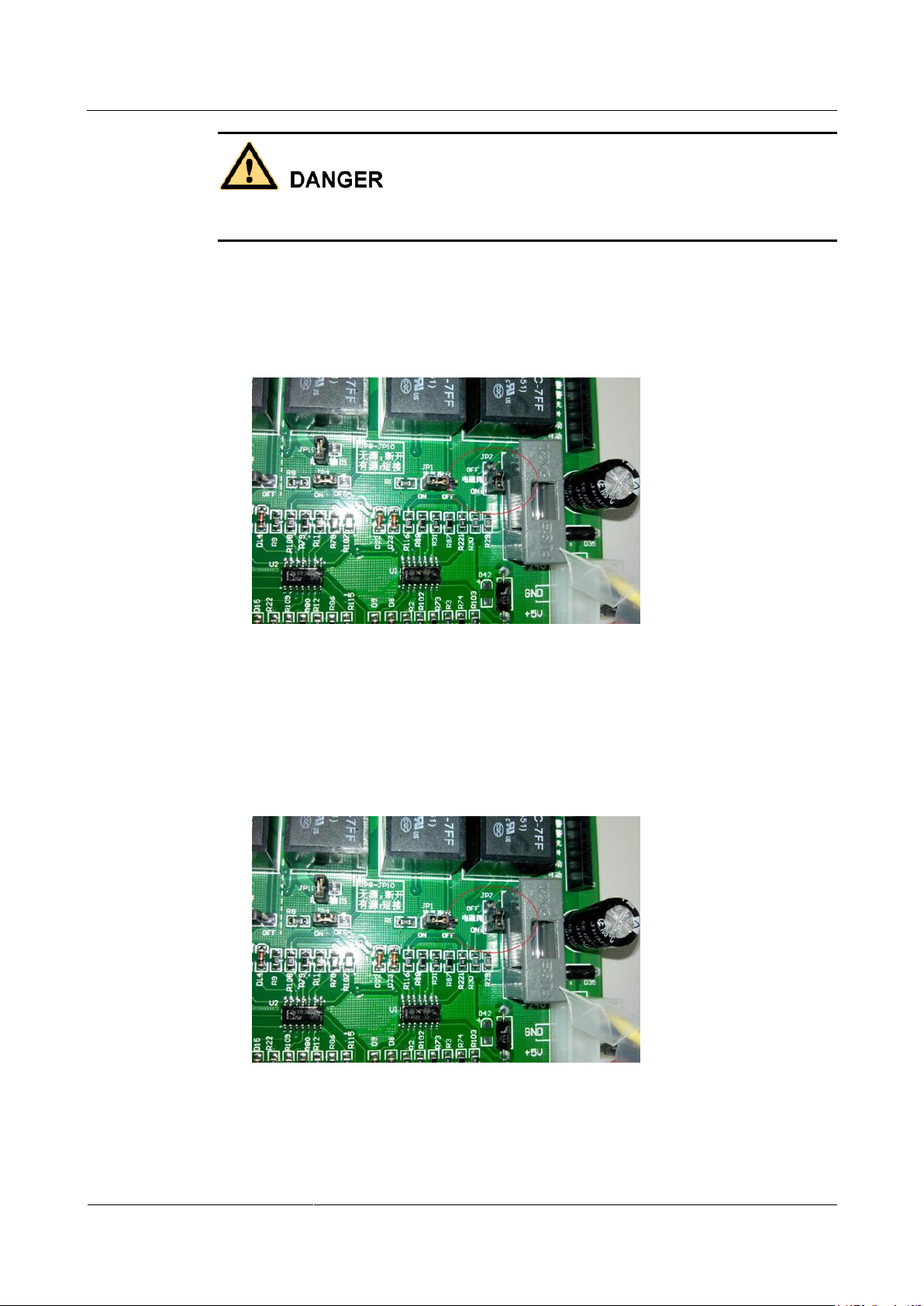
jumper state is not OFF, adjust it to OFF. Figure 3-4 shows the position to be set.
Figure 3-4 Setting the test mode for the solenoid valve
2. If the system is configured with two or more fire extinguishing cylinders and no fire
extinguishing power box is configured (mode of the fire extinguishing power module
SJ-DYX-0607, with relays and batteries). Ensure that the jumper state of JP7 is ON (not
detecting faults). If the jumper state is not ON, adjust it to ON Figure 3-5 shows the
position to be set.
Figure 3-5 Setting the test mode for the solenoid valve
Step 4 Set the power-on delay for the solenoid valve.
Set the power-on delay for the solenoid valve from 25s to 30s, as shown in Figure 3-6.
Page 22

IDS1000 Container Data Center
User Manual
3 Power-On Commissioning
Issue 01 (2014-3-15)
Huawei Proprietary and Confidential
Copyright © Huawei Technologies Co., Ltd.
16
Figure 3-6 Setting the power-on delay for the solenoid valve from 25s to 30s
The factory setting for the solenoid valve power-on delay is 30s, as shown in Figure 3-7.
Figure 3-7 Setting the initial power-on delay for the solenoid valve
Step 5 Set the gas extinguishing controller time display.
Open the controller panel and calibrate time from the rear of the display panel.
There are three buttons and one light emitting diode on the rear of the panel. The three buttons are
Switchover S12, Former plus S11, and Later plus S10, respectively, which are used to calibrate time.
Former plus means plus 1 for the first two values of the nixie tube, and Later plus means
plus 1 for the last two values of the nixie tube. The adjustment methods are as follows:
1. Press Switchover S12, and the H11 indicator lights up, indicating that the time is being
calibrated. The nixie tube displays the year in the format of ??. Press Later plus S10 to
add the value, which ranges from 1 to 60.
2. Then press Switchover S12, and the nixie tube displays the month and day in the format
of ??.??.
Press Former plus S11 to adjust the month, which ranges from 1 to 12, and then press
Later plus S10 to adjust the date, which ranges from 1 to 31.
3. Press Switchover S12 again to display hour and minute, which is in the format of ??:??.
Press Former plus S11 to adjust the month, which ranges from 1 to 23. Then press
Later plus S10 to adjust the day, which ranges from 0 to 59.
4. Press Switchover S12 again to finish the time setting. The indicator H11 lights off. The
nixie tube displays the hour and minute.
Page 23

IDS1000 Container Data Center
User Manual
3 Power-On Commissioning
Issue 01 (2014-3-15)
Huawei Proprietary and Confidential
Copyright © Huawei Technologies Co., Ltd.
17
----End
3.2 Checking Before Power-On
Prerequisites
You have completed the power-on for the Power Supply and Distribution System and the
fire extinguishing power distribution box (PDB) in the container data center.
Before the power-on, ensure that you have been familiarized with the function and control
relationship of each circuit breaker in the Power Supply and Distribution System. For details
about the function and control relationship of each circuit breaker in the Power Supply and
Distribution System, see the corresponding descriptions in the Container Data Center Initial
Configuration Guide.
Procedure
Step 1 Configure and check the initial parameter settings of the fire extinguishing system by
referring to the Container Data Center Initial Configuration Guide.
For details about how to configure and check the parameters, see 3.1 Initial Configuration.
Step 2 Check the cable connections of solenoid valves. Disconnect the control cables to solenoid
valves to prevent the fire extinguishing equipment from malfunctioning due to improper
manual operations. Figure 3-8 shows the solenoid valve.
Figure 3-8 Solenoid valve
Page 24

IDS1000 Container Data Center
User Manual
3 Power-On Commissioning
Issue 01 (2014-3-15)
Huawei Proprietary and Confidential
Copyright © Huawei Technologies Co., Ltd.
18
Step 3 Check whether the emergency shutdown button short-circuit cable (between terminals 19 and
GND) is disconnected. If not, disconnect the cable and do not reconnect it after that. Ensure
that the cable to terminal 19 is red and that to GNT is black. Ensure that the short-circuit cable
between terminals 20 and GND is properly connected (in the manual switchover state), as
shown in Figure 3-9.
Figure 3-9 Cable to the emergency start/abort switch
Step 4 Check the battery cable connection. Figure 3-10 shows the correct cable connections.
Figure 3-10 Connecting battery cables
Step 5 Check the cable connections between other components and the gas extinguishing controller
in the fire extinguishing system.
Step 6 Ensure that cable labels are correct, intact, and clearly legible.
Step 7 Ensure that the input circuit breaker for the gas extinguishing controller is OFF.
Step 8 Ensure that the input circuit breaker for the VESDA power box is OFF.
Step 9 Ensure that the cable connections for the VESDA power box batteries are correct and the
power box is correctly connected to the host.
Step 10 Ensure that the power for the gas extinguishing controller and VESDA power box circuit
breakers meets rated voltage and current requirements.
Page 25

IDS1000 Container Data Center
User Manual
3 Power-On Commissioning
Issue 01 (2014-3-15)
Huawei Proprietary and Confidential
Copyright © Huawei Technologies Co., Ltd.
19
Before the power-on of the container data center fire extinguishing system, check all the fire
extinguishing components one by one by following the preceding check methods and items.
----End
3.3 Hardware Power-On Commissioning
Prerequisites
You have completed the power-on check.
You have obtained the Container Data Center Initial Configuration Guide and Container
Data Center Power-On Commissioning Guide.
You have obtained the documents delivered with the fire extinguishing devices.
Procedure
Step 1 Switch on the input circuit breaker for the VESDA power box in the corresponding protected
zone. For details, see the Container Data Center Initial Configuration Guide and Container
Data Center Power-On Commissioning Guide.
Step 2 Complete the power-on commissioning for the VESDA. For details, see the delivered
VESDA documents.
If multiple VESDAs are configured in the protected zone, follow the preceding power-on
operations to power on their hardware.
Step 3 Switch on the input circuit breaker for the gas extinguishing controller in the corresponding
protected zone. For details, see the Container Data Center Initial Configuration Guide and
Container Data Center Power-On Commissioning Guide.
Step 4 Turn on the main power and backup power switches for the controller to power on the gas
extinguishing controller. Figure 3-11 shows the positions of the switches.
Page 26

IDS1000 Container Data Center
User Manual
3 Power-On Commissioning
Issue 01 (2014-3-15)
Huawei Proprietary and Confidential
Copyright © Huawei Technologies Co., Ltd.
20
Figure 3-11 Power switches
Step 5 Unlock the keypad.
The keypad is locked to prevent misoperation. To unlock the keypad, press /KEY ON/OFF
and then press /QUERY TIME. The keypad is unlocked and the keypad indicator is on. To
lock the keypad, press /KEYON/OFF. The keypad indicator is off. The key will be locked if
no operation is performed in 4 minutes.
Step 6 Start or stop the audible and visual alarm.
When the keypad is unlocked, press /HORN/STROBE to start or stop the audible and visual
alarm. After the audible and visual alarm is started, the indicator beside the button is on.
Step 7 Start or stop the alarm bell.
When the keypad is unlocked, press /ALARM BELL to start or stop the alarm bell. After the
alarm bell is started, the indicator beside the button is on.
Step 8 Check that all smoke detector and heat detector indicators work properly.
Normally, the indicators blink once every 6 seconds.
Step 9 Check that emergency startup/abort switch indicators work properly.
Normally, the Run indicator is steady on.
When powering on and commissioning the hardware of the fire extinguishing system, commission all
the fire extinguishing devices in the container data center. For details about the positions of each fire
extinguishing device, see the Container Data Center Initial Configuration Guide.
----End
3.4 Fire Extinguishing System Commissioning
Commission the fire extinguishing system before using the container data center to ensure that
the system works properly.
Page 27

IDS1000 Container Data Center
User Manual
3 Power-On Commissioning
Issue 01 (2014-3-15)
Huawei Proprietary and Confidential
Copyright © Huawei Technologies Co., Ltd.
21
Prerequisites
You have completed the power-on for the fire extinguishing system.
The monitoring system is working properly.
Smoke and heat generators have been prepared.
The main task involves commissioning of fire extinguishing association, which can be
operated only by professionals in this field.
Before commissioning the system, ensure that all control cables to solenoid valve drivers
have been disconnected. This prevents the fire extinguishing equipment from
malfunctioning due to improper manual operations or incorrect cable connections, and
further prevents accidental damage. After the commissioning is complete, reconnect the
solenoid valves.
Before commissioning the system, perform the jumper operation for the passive output.
Otherwise, the 6 A fuse (5D) on the main board will be damaged.
If a blow drier is used to simulate the high-temperature scenario, do not get too close to the
detector to avoid the damage of the detector probe caused by high temperature.
Procedure
Step 1 Commission the VESDA.
Step 2 Check whether the gas extinguishing controller is in the automatic mode (the controller has
Release some smoke to the protected zone using a smoke pistol and observe the reaction of
the VESDA.
two modes: automatic and manual).
The AUTO indicator lights up when the controller enters automatic mode, and the MANUAL
indicator lights up when the controller enters manual mode. The positions of the indicators are
as shown in Figure 3-12.
Page 28

IDS1000 Container Data Center
User Manual
3 Power-On Commissioning
Issue 01 (2014-3-15)
Huawei Proprietary and Confidential
Copyright © Huawei Technologies Co., Ltd.
22
Figure 3-12 AUTO and MANUAL indicators on the gas extinguishing controller panel
If the status is manual, no solenoid valve driving signals will be generated from the controller when the
dual fire alarms from the smoke detector and heat detector are triggered.
Step 3 Simulate to trigger the smoke detector and heat detector.
When the gas extinguishing controller is tested and the first and second fire alarms are
triggered in sequence, the first loop indicator on the panel turns from off to blinking, and the
second loop indicator turns from off to steady on, which are normal reactions.
1. Use a conductor to short-circuit terminals 26 and GND to simulate to trigger the smoke
detector, as shown in Figure 3-13.
Figure 3-13 Short-circuiting terminals 26 and GND
Page 29

IDS1000 Container Data Center
User Manual
3 Power-On Commissioning
Issue 01 (2014-3-15)
Huawei Proprietary and Confidential
Copyright © Huawei Technologies Co., Ltd.
23
After the short-circuiting, a smoke detector loop alarm is triggered, and the loop 1
indicator on the gas extinguishing controller panel blinks in red, as shown in Figure 3-14.
The controller reports a single loop alarm and the fire extinguishing alarm bell alarms.
Figure 3-14 Loop 1 indicator on the gas extinguishing controller panel
You can also use a smoke pistol to release smoke near the smoke detector until the detector is
triggered.
Do not clear the alarm. Proceed to the alarm simulation for the heat detector.
2. Use a conductor to short-circuit terminals 25 and GND to simulate to trigger the heat
detector, as shown in Figure 3-15.
Figure 3-15 Short-circuiting terminals 25 and GND
Page 30

IDS1000 Container Data Center
User Manual
3 Power-On Commissioning
Issue 01 (2014-3-15)
Huawei Proprietary and Confidential
Copyright © Huawei Technologies Co., Ltd.
24
After the short-circuiting, a heat detector loop alarm is triggered, and the loop 2 indicator
on the gas extinguishing controller panel is steady red, as shown in Figure 3-16.
The controller generates another loop fire alarm. The audible and visual alarm begins to
operate and enter the 30s countdown mode.
Figure 3-16 Loop 2 indicator on the gas extinguishing controller panel
You can also use a blow drier or heat gun to blow hot air near the heat detector until the detector is
triggered.
3. Measure the output voltage of the solenoid valve.
After the countdown is completed, use a multimeter to measure the output voltage for the
solenoid valve, and ensure that the voltage ranges from 24 V to 27.5 V, as shown in
Figure 3-17. The gas release indicator turns on at the same time.
Figure 3-17 Measuring the voltages for the two terminals of the solenoid valve
Page 31
IDS1000 Container Data Center
User Manual
3 Power-On Commissioning
Issue 01 (2014-3-15)
Huawei Proprietary and Confidential
Copyright © Huawei Technologies Co., Ltd.
25
Step 4 Commission the pressure annunciator.
1. Reset the gas extinguishing controller to automatic and disconnect the cables from the
solenoid valve.
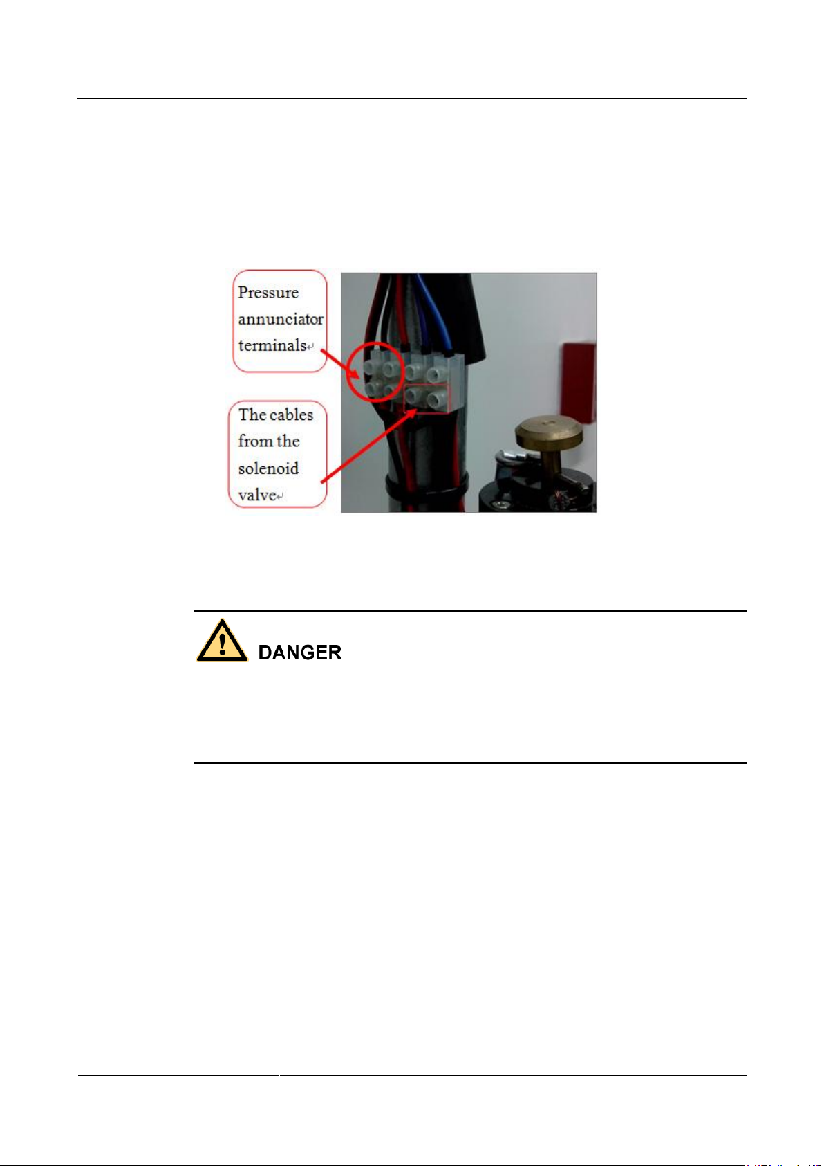
2. Short-circuit the pressure annunciator cables (red and black), as shown in Figure 3-18.
The gas release indicator should light up.
Figure 3-18 Short-circuiting the pressure annunciator terminals
Step 5 Commission the emergency startup/abort switch.
The panel of the emergency startup/abort switch is for one-time use only. Before the
commissioning, remove the panel to perform an operation on the emergency startup/abort
switch directly, as shown in Figure 3-19.
Reset the emergency startup/abort switch after the commissioning (the switch is bounced up
and not pressed).
Page 32

IDS1000 Container Data Center
User Manual
3 Power-On Commissioning
Issue 01 (2014-3-15)
Huawei Proprietary and Confidential
Copyright © Huawei Technologies Co., Ltd.
26
Figure 3-19 Emergency startup/abort switch (panel not removed on the left, panel removed on the
right)
Press the startup button, the system enters the gas releasing delay mode, and the audible and
visual alarm begins to operate. After the countdown is complete, solenoid valve driving
signals are generated and the gas release indicator lights up. If you press the shutdown button
during the delay, the system will stop generating the solenoid valve driving signals.
Step 6 Test the functions of detectors.
Remove the smoke detector or heat detector from the base, as shown in Figure 3-20. Simulate
a network failure for the smoke detector or heat detector in this loop. The gas extinguishing
controller should report relevant loop faults, as shown in Figure 3-21. Reinstall the smoke
detector or heat detector, and the fault is rectified.
Figure 3-20 Removing detectors
Page 33

IDS1000 Container Data Center
User Manual
3 Power-On Commissioning
Issue 01 (2014-3-15)
Huawei Proprietary and Confidential
Copyright © Huawei Technologies Co., Ltd.
27
Figure 3-21 Loop fault alarm indicators for the smoke detector and heat detector (Zone 1 for the
smoke detector, and Zone 2 for the heat detector).
Step 7 After the test is complete, reset the gas extinguishing controller.
Step 8 (Optional) Check that the fire control signals are reported to the monitoring center.
Page 34

IDS1000 Container Data Center
User Manual
3 Power-On Commissioning
Issue 01 (2014-3-15)
Huawei Proprietary and Confidential
Copyright © Huawei Technologies Co., Ltd.
28
The fire extinguishing system meets requirements if operations during the commissioning
have expected results and corresponding alarms are generated in the iManager NetEco
management system.
The system can be put into use if operations during the commissioning have expected
results.
To ensure the normal operation of the fire extinguishing system, the dowel tightening the
fire cylinder solenoid valve and the container valve must be removed. Figure 3-22 shows
the dowel.
Figure 3-22 Dowel tightening the fire cylinder solenoid valve
----End
Page 35

IDS1000 Container Data Center
User Manual
4 Routine Maintenance
Issue 01 (2014-3-15)
Huawei Proprietary and Confidential
Copyright © Huawei Technologies Co., Ltd.
29
4 Routine Maintenance
Maintenan
ce Item
Operation
Expected
Result
Troubleshooting
Fire alarm
Check gas fire
extinguishing
No fire
alarms are
If an alarm is generated, take
actions immediately. For details,
4.1 Routine Maintenance Overview
Routine Maintenance
Routine maintenance is scheduled maintenance carried out to ensure proper system operating
and to therefore avoid any unscheduled breakdown and downtime.
Routine maintenance helps the O&M personnel to:
Find and handle alarms related to equipment operating in a timely manner.
Discover potential risks in a timely manner, preventing faults that could possibly cause
economic losses and reduce customer satisfaction.
Analyze the system operating trend based on collected information and take measures to
improve operating efficiency.
Emergency maintenance is a process of rectifying a fault occurred during the system operation. For
details, see 1 Configuration Description.
Routine Maintenance Interval
The routine maintenance interval specifies how often a maintenance task is performed. A
maintenance task can be performed on a daily, weekly, monthly, quarterly, semi-annual, or
annual basis. For example, if the maintenance interval for a task is daily, the task is performed
every day.
In this document, if a maintenance task is not given a fixed maintenance interval, determine the
maintenance interval based on actual situation of the container data center.
4.2 Daily Maintenance
Page 36

IDS1000 Container Data Center
User Manual
4 Routine Maintenance
Issue 01 (2014-3-15)
Huawei Proprietary and Confidential
Copyright © Huawei Technologies Co., Ltd.
30
Maintenan
ce Item
Operation
Expected
Result
Troubleshooting
controllers for alarms.
generated.
see the emergency operations for
the fire extinguishing system.
Maintenan
ce Item
Operation
Expected
Result
Troubleshooting
Fire
extinguisher
s
Check whether the fire
extinguishers are in
good condition.
Check the validity
period of fire
extinguishers.
The fire
extinguishers
are in good
condition and
within the
validity
period.
If a fire extinguisher is not in
good condition or has expired,
replace the fire extinguisher.
Maintena
nce Item
Operation
Expected Result
Troubleshooting
Appearance
of
cabinet-type
gas
extinguisher
components
, including
the
extinguishin
g agent
vessel,
solenoid
valve
driver,
pipes, and
nozzles
Check all
components of
the cabinet-type
gas
extinguishers.
The components are
free from mechanical
damage.
The components are
free from rust and
corrosion, the
protective coating is
intact, and the
nameplate is clear.
The protective cover,
lead seal, and safety
signs on
hand-operated
devices are intact.
Devices, pipes,
supports, and
hangers in the
extinguishing agent
If components are bent due to
collision, contact Huawei
technical support.
4.3 Weekly Maintenance
Gas extinguishers are optional for the container data center. The weekly maintenance tasks may vary
with the fire extinguishers you use.
4.4 Monthly Maintenance
Page 37

IDS1000 Container Data Center
User Manual
4 Routine Maintenance
Issue 01 (2014-3-15)
Huawei Proprietary and Confidential
Copyright © Huawei Technologies Co., Ltd.
31
Maintena
nce Item
Operation
Expected Result
Troubleshooting
vessel are installed
securely.
All nozzle openings
are not blocked.
Gas
pressure of
the fire
cylinder
Observe the
pointer on the
barometer of
the fire
cylinder.
The pointer is in the
green area.
If the pointer is not in the
green area, contact Huawei
technical support.
Maintena
nce Item
Operation
Expected
Result
Troubleshooting
Alarm
indicator on
smoke
detectors
Observe the
alarm indicator
on each smoke
detector.
The alarm
indicator blinks
once every six
seconds.
If an alarm indicator blinks twice
every six seconds or does not blink,
the smoke detector is faulty or the
cables are not properly connected.
Connect the cables or replace the
smoke detector. For details, see the
operations described in 6.1 Smoke
Detector Fault.
Alarm
indicator on
heat
detectors
Observe the
alarm indicator
on each heat
detector.
The alarm
indicator blinks
once every six
seconds.
If an alarm indicator blinks twice
every six seconds or does not blink,
the heat detector is faulty or the cable
is not properly connected. Connect
the cables or replace the heat
detector. For details, see the
operations described in 6.2 Heat
Detector Fault.
Audible and
visual alarm
Trigger a
smoke detector
and a heat
detector.
Audible and
visual alarms are
generated.
If no alarm is generated, the audible
and visual alarm is faulty or the cable
is not properly connected. Rectify the
fault by following the instructions in
6.4 Audible and Visual Alarm Fault.
Fire alarm
bell
Trigger a
smoke detector
or a heat
detector.
The fire alarm
bell rings.
If the fire alarm bell does not ring,
the alarm bell is faulty or the cable is
not properly connected. Connect the
cable or replace the alarm bell. For
details, see the operations described
in 6.5 Fire Alarm Bell Fault.
4.5 Quarterly Maintenance
Page 38

IDS1000 Container Data Center
User Manual
4 Routine Maintenance
Issue 01 (2014-3-15)
Huawei Proprietary and Confidential
Copyright © Huawei Technologies Co., Ltd.
32
4.6 Semi-Yearly Maintenance
Maintena
nce Item
Operation
Expected
Result
Troubleshooting
VESDA air
detector
network
Check the connection of
air detectors.
The air detectors
are securely
connected.
Connect the air detectors
securely.
Smoke
detectors
Use a dedicated test
instrument or a smoke
generator to blow
smoke to a smoke
detector and check the
indicator status on the
smoke detector.
If the smoke
density is
below the
alarm
threshold, the
alarm
indicator
blinks once
every six
seconds.
If the smoke
density
exceeds the
alarm
threshold, the
alarm
indicator is
steady on.
If the smoke density is
below the alarm threshold
but the alarm indicator
blinks twice every six
seconds, the smoke
detector is faulty. Replace
the smoke detector.
If the smoke density
exceeds the alarm
threshold but the alarm
indicator is not steady on,
replace the smoke
detector.
For details about how to
replace a smoke detector, see
7.1 Replacing a Smoke
Detector.
NOTE
You are advised to clean smoke
detectors every two years.
Heat
detectors
Use a dedicated test
instrument or a blow
drier to check the heat
detectors. Observe the
alarm indicator.
NOTICE
To prevent damage to the
heat detector probe, keep
a proper distance between
the sensor probe and the
blower drier.
If the
temperature
is below the
alarm
threshold, the
alarm
indicator is
blinking.
If the
temperature
exceeds the
alarm
threshold, the
alarm
indicator is
steady on.
If the temperature is
below the alarm threshold
but the alarm indicator is
steady on, replace the
heat detector.
If the temperature
exceeds the alarm
threshold but the alarm
indicator is not steady on
(that is, no alarm is
generated), replace the
heat detector.
For details about how to
replace a heat detector, see
7.2 Replacing a Heat
Detector.
Page 39

IDS1000 Container Data Center
User Manual
4 Routine Maintenance
Issue 01 (2014-3-15)
Huawei Proprietary and Confidential
Copyright © Huawei Technologies Co., Ltd.
33
4.7 Yearly Maintenance
Maintena
nce Item
Operation
Expected Result
Troubleshooting
Other
maintenanc
e tasks of
the VESDA
For details, see the documents delivered with the VESDA.
Fire
extinguishin
g system
commission
ing
For details, see the 3.4 Fire Extinguishing
System Commissioning.
See the troubleshooting and
alarm handling procedure of
the fire extinguishing system.
Page 40

IDS1000 Container Data Center
User Manual
5 Alarm Reference
Issue 01 (2014-3-15)
Huawei Proprietary and Confidential
Copyright © Huawei Technologies Co., Ltd.
34
5 Alarm Reference
Alarm
Alarm
Severit
y
Alarm
Type
Impact on the
System
Solution
Gas
extinguish
ing
controller
communic
ation
failure
Critical
Event
The fire
extinguishing
system cannot
be monitored.
See the documents delivered with the
gas extinguishing controller.
Fire
extinguish
ing
hardware
fault
Critical
Event
The fire
extinguishing
system does not
work.
1. Check whether the fire
extinguishing components are in
good condition and properly
connected.
If yes, contact Huawei
technical support.
If no, go to 2.
2. Rectify the fault and check
whether the alarm is cleared.
If yes, no further action is
required.
If no, contact Huawei technical
support.
Fire
extinguish
ing
triggered
Critical
Alarm
The fire
extinguishing
equipment has
released
extinguishing
agents into the
protected zone
of the container.
Check whether a fire is present in the
container.
If yes, fire extinguishing cylinders are
triggered. Wait for the fire
extinguishing system to respond.
If no, check whether fire
extinguishing cylinders are triggered.
If the fire extinguishing cylinders
are triggered, press the shutdown
button on the emergency
startup/abort switch to stop fire
Page 41

IDS1000 Container Data Center
User Manual
5 Alarm Reference
Issue 01 (2014-3-15)
Huawei Proprietary and Confidential
Copyright © Huawei Technologies Co., Ltd.
35
Alarm
Alarm
Severit
y
Alarm
Type
Impact on the
System
Solution
extinguishing actions. Then see
6.6 Failed to Drive the Fire
Cylinder.
If the fire extinguishing cylinders
are not triggered, see 6.6 Failed to
Drive the Fire Cylinder.
Page 42

IDS1000 Container Data Center
User Manual
6 Troubleshooting
Issue 01 (2014-3-15)
Huawei Proprietary and Confidential
Copyright © Huawei Technologies Co., Ltd.
36
6.1 Smoke Detector Fault
Possible Causes
The power supply to the smoke detector is abnormal.
The smoke detector is faulty.
The cable connection of the smoke detector is abnormal.
6 Troubleshooting
Tools and Materials
Multimeter
Screwdriver
Step ladder
Spare smoke detectors
Procedure
Step 1 Check whether the power supply to the smoke detector is abnormal.
In normal conditions, use a multimeter to measure the common terminal (base terminal 1) and
the signal terminal (base terminal 3) and check whether the voltage is about 24 V.
Y => The voltage is normal. Go to Step 2.
N => Regulate the voltage to a normal value.
Check whether the fault is rectified.
If yes, no further action is required.
If no, go to Step 2.
Step 2 Replace the smoke detector.
Check whether the fault is rectified.
If yes, no further action is required.
If no, go to Step 3.
Step 3 Check the cable connection of the sensor base.
Page 43

IDS1000 Container Data Center
User Manual
6 Troubleshooting
Issue 01 (2014-3-15)
Huawei Proprietary and Confidential
Copyright © Huawei Technologies Co., Ltd.
37
Figure 6-1 shows the positions and functions of terminals on the sensor base.
Figure 6-1 Terminals on the sensor base
Terminals (no polarity, two-wire)
1: L2 (connected to the common terminal)
2: L1 (connected to a lower-level device)
3: L1 (connected to an upper-level device)
4: reserved
Use a multimeter to check whether there is any short circuit or open circuit.
Y => Rectify the connection fault.
Check whether the fault is rectified.
If yes, no further action is required.
If no, contact Huawei technical support.
N => Contact Huawei technical support.
----End
6.2 Heat Detector Fault
Possible Causes
The power supply to the heat detector is abnormal.
The heat detector is faulty.
The cable connection of the heat detector is abnormal.
Tools and Materials
Multimeter
Page 44

IDS1000 Container Data Center
User Manual
6 Troubleshooting
Issue 01 (2014-3-15)
Huawei Proprietary and Confidential
Copyright © Huawei Technologies Co., Ltd.
38
Procedure
Step 1 Check whether the power supply to the heat detector is abnormal.
Step 2 Y=> Replace the heat detector.
Screwdriver
Step ladder
Spare heat detector
In normal conditions, use a multimeter to measure the common terminal (base terminal 1) and
the signal terminal (base terminal 3) and check whether the voltage is about 24 V.
Y => Go to Step 2.
N => Regulate the voltage to a normal value.
Check whether the fault is rectified.
If yes, no further action is required.
If no, go to Step 2.
Check whether the fault is rectified.
If yes, no further action is required.
If no, go to Step 3.
Step 3 Check the cable connection of the sensor base.
Figure 6-2 shows the positions and functions of terminals on the sensor base.
Figure 6-2 Terminals on the sensor base
Terminals (no polarity, two-wire)
Page 45

IDS1000 Container Data Center
User Manual
6 Troubleshooting
Issue 01 (2014-3-15)
Huawei Proprietary and Confidential
Copyright © Huawei Technologies Co., Ltd.
39
1: L2 (connected to the common terminal)
2: L1 (connected to a lower-level device)
3: L1 (connected to an upper-level device)
4: reserved
Use a multimeter to check whether there is any short circuit or open circuit.
Y => Rectify the connection fault.
Check whether the fault is rectified.
If yes, no further action is required.
If no, contact Huawei technical support.
N => Contact Huawei technical support.
----End
6.3 Gas Release Indicator Fault
Possible Causes
The power supply to the gas release indicator is abnormal.
The gas release indicator is faulty.
The cable connection of the gas release indicator is abnormal.
Tools and Materials
Multimeter
Gloves
Screwdriver
Step ladder
Procedure
Step 1 Check the power supply to the gas release indicator.
Short circuit the pressure annunciator after the cable is removed from the solenoid valve.
When the gas release indicator is off, use a multimeter to measure the two terminals (24 V+
and GND) of the gas release indicator. Check whether the voltage is within the normal range.
Y => Go to Step 2.
N => Regulate the voltage to a normal value.
Check whether the fault is rectified.
If yes, no further action is required.
If no, go to Step 2.
Step 2 Replace the gas release indicator.
Check whether the fault is rectified.
If yes, no further action is required.
Page 46

IDS1000 Container Data Center
User Manual
6 Troubleshooting
Issue 01 (2014-3-15)
Huawei Proprietary and Confidential
Copyright © Huawei Technologies Co., Ltd.
40
If no, go to Step 3.
Step 3 Check the connection between the gas release indicator and the controller.
Use a multimeter to check whether there is any short circuit or open circuit.
Y => Rectify the connection fault.
Check whether the fault is rectified.
If yes, no further action is required.
If no, contact Huawei technical support.
N => Contact Huawei technical support.
----End
6.4 Audible and Visual Alarm Fault
Possible Causes
The power supply to the audible and visual alarm is abnormal.
The audible and visual alarm is faulty.
The cable connection of the audible and visual alarm is abnormal.
Tools and Materials
Multimeter
Screwdriver
Step ladder
Procedure
Step 1 Check the power supply to the audible and visual alarm.
Trigger a smoke alarm and a temperature alarm when the cable is removed from the solenoid
valve, and observe whether audible and visual alarms are generated. Use a multimeter to
measure the DC24V+ and GND terminals of the audible and visual alarm, and check whether
the voltage is within normal range.
Y => Go to Step 2.
N => Regulate the voltage to a normal value.
Check whether the fault is rectified.
If yes, no further action is required.
If no, go to Step 2.
Step 2 Replace the audible and visual alarm.
Check whether the fault is rectified.
If yes, no further action is required.
If no, go to Step 3.
Page 47

IDS1000 Container Data Center
User Manual
6 Troubleshooting
Issue 01 (2014-3-15)
Huawei Proprietary and Confidential
Copyright © Huawei Technologies Co., Ltd.
41
Step 3 Check the connection between the audible and visual alarm and the controller.
Figure 6-3 shows the terminals on the audible and visual alarm.
Figure 6-3 Terminals on the audible and visual alarm
Terminals (two-wire):
1: reserved
2: +24 V positive
3: GND negative
4: reserved
Use a multimeter to check whether there is any short circuit or open circuit.
Y => Rectify the connection fault.
Check whether the fault is rectified.
Check whether the fault is rectified.
If yes, no further action is required.
If no, contact Huawei technical support.
N => Contact Huawei technical support.
----End
Page 48

IDS1000 Container Data Center
User Manual
6 Troubleshooting
Issue 01 (2014-3-15)
Huawei Proprietary and Confidential
Copyright © Huawei Technologies Co., Ltd.
42
6.5 Fire Alarm Bell Fault
Possible Causes
The power supply to the fire alarm bell is abnormal.
The fire alarm bell is faulty.
The cable connection of the fire alarm bell is abnormal.
Tools and Materials
Multimeter
Gloves
Step ladder
Screwdriver
Procedure
Step 1 Check whether the power supply to the fire alarm bell is abnormal.
Trigger a smoke alarm and a temperature alarm when the cable is removed from the solenoid
valve, and observe whether the fire alarm bell rings. Use a multimeter to measure the two
terminals of the alarm bell, and check whether the voltage is within normal range.
Y => Go to Step 2.
N => Regulate the voltage to a normal value.
Check whether the fault is rectified.
If yes, no further action is required.
If no, go to Step 2.
Step 2 Replace the fire alarm bell.
Check whether the fault is rectified.
If yes, no further action is required.
If no, go to Step 3.
Step 3 Check the connection between the fire alarm bell and the controller.
Use a multimeter to check whether there is any short circuit or open circuit.
Y => Rectify the connection fault.
Check whether the fault is rectified.
If yes, no further action is required.
If no, contact Huawei technical support.
N => Contact Huawei technical support.
----End
Page 49

IDS1000 Container Data Center
User Manual
6 Troubleshooting
Issue 01 (2014-3-15)
Huawei Proprietary and Confidential
Copyright © Huawei Technologies Co., Ltd.
43
6.6 Failed to Drive the Fire Cylinder
Possible Causes
The gas cylinder is not driven successfully.
Cable connection of the gas cylinder is abnormal.
Tools and Materials
Gloves
Multimeter
Screwdriver
Procedure
Step 1 Check whether the gas cylinder is driven successfully.
Y => Contact Huawei technical support.
N => Go to Step 2.
Step 2 Replace the driving device of the gas cylinder.
Check whether the fault is rectified.
Y => No further action is required.
N => Contact Huawei technical support.
----End
6.7 VESDA Fault
For details about how to rectify VESDA faults, see the documents delivered with the VESDA
or contact Huawei technical support.
6.8 Gas Extinguishing Controller Fault
Possible Causes
The gas extinguishing controller is not properly connected.
The gas extinguishing controller is faulty.
Tools and Materials
Documents delivered with the gas extinguishing controller
Screwdriver
Gloves
Dedicated keys to the controller box
Page 50

IDS1000 Container Data Center
User Manual
6 Troubleshooting
Issue 01 (2014-3-15)
Huawei Proprietary and Confidential
Copyright © Huawei Technologies Co., Ltd.
44
Procedure
Step 1 Check the cable connection of the gas extinguishing controller.
Step 2 Check the gas extinguishing controller.
1. Check whether the cable connection is normal.
Y => Go to Step 2.
N => Go to Step 1.2.
2. Replace the faulty cable.
Check whether the fault is rectified.
If yes, no further action is required.
N => Go to Step 2.
1. Check whether the gas extinguishing controller is faulty.
Y => Go to Step 2.2.
N => Contact Huawei technical support.
2. Replace the gas extinguishing controller.
Check whether the fault is rectified.
Y => No further action is required.
N => Contact Huawei technical support.
----End
Page 51

IDS1000 Container Data Center
User Manual
7 Parts Replacement
Issue 01 (2014-3-15)
Huawei Proprietary and Confidential
Copyright © Huawei Technologies Co., Ltd.
45
7 Parts Replacement
7.1 Replacing a Smoke Detector
Prerequisites
A smoke detector needs to be replaced.
Spare smoke detectors are available.
Tools and Materials
Spare smoke detectors
Gloves
Step ladder
Preparations
Before replacing the smoke detector, inform the related administration department of
temporary downtime of the fire control system. In addition, disable the logical control
function of the area or system to prevent false alarms. Inform the related departments of the
system recovery after the replacement is complete.
Impact on the System
None
Procedure
Step 1 Hold the smoke detector and turn it anticlockwise to remove it from the base.
Page 52

IDS1000 Container Data Center
User Manual
7 Parts Replacement
Issue 01 (2014-3-15)
Huawei Proprietary and Confidential
Copyright © Huawei Technologies Co., Ltd.
46
A loop fault alarm is generated. No action needs to be taken.
Step 2 Power off the gas fire extinguishing controllers, and connect a new smoke detector.
Figure 7-1 shows the terminals on the sensor base.
Figure 7-1 Terminals on the base
Terminals (no polarity, two-wire)
1: L2 (connected to the common terminal)
2: L1 (connected to a lower-level device)
3: L1 (connected to an upper-level device)
4: reserved
Step 3 Align the smoke detector indicator with B on the base, insert the smoke detector in the base,
and turn it clockwise until the smoke detector is firmly secured.
Step 4 Power on the gas fire extinguishing controller.
Page 53

IDS1000 Container Data Center
User Manual
7 Parts Replacement
Issue 01 (2014-3-15)
Huawei Proprietary and Confidential
Copyright © Huawei Technologies Co., Ltd.
47
Step 5 If the red indicator on the smoke detector blinks every 6 seconds, the smoke detector is
working properly.
Step 6 Check that the new smoke detector is working properly.
----End
Follow-up Procedure
Send the faulty smoke detector together with a Repair Notice to your local Huawei office for
repair.
7.2 Replacing a Heat Detector
Prerequisites
A heat detector needs to be replaced.
Spare heat detectors are available.
Tools and Materials
Spare heat detectors
Gloves
Step ladder
Preparations
Before replacing the heat detector, inform the related administration department of temporary
downtime of the fire control system. In addition, disable the logical control function of the
area or system to prevent false alarms. Inform the related departments of the system recovery
after the replacement.
Impact on the System
None
Procedure
Step 1 Hold the faulty heat detector and turn it anticlockwise to remove it from the base.
Page 54

IDS1000 Container Data Center
User Manual
7 Parts Replacement
Issue 01 (2014-3-15)
Huawei Proprietary and Confidential
Copyright © Huawei Technologies Co., Ltd.
48
A loop fault alarm is generated. No action needs to be taken.
Step 2 Power off the gas fire extinguishing controllers, and connect a new heat detector.
Figure 7-2 shows the terminals on the sensor base.
Figure 7-2 Terminals on the base
Terminals (no polarity, two-wire)
1: L2 (connected to the common terminal)
2: L1 (connected to a lower-level device)
3: L1 (connected to an upper-level device)
4: reserved
Step 3 Align the heat detector indicator with B on the base, insert the sensor in the base, and turn it
clockwise until the heat detector is firmly secured.
Page 55

IDS1000 Container Data Center
User Manual
7 Parts Replacement
Issue 01 (2014-3-15)
Huawei Proprietary and Confidential
Copyright © Huawei Technologies Co., Ltd.
49
Step 4 Power on the gas fire extinguishing controller.
Step 5 If the red indicator on the heat detector blinks every 6 seconds, the heat detector is working
properly.
Step 6 Check that the new heat detector is working properly.
----End
Follow-up Procedure
Send the faulty heat detector together with a Repair Notice to your local Huawei office for
repair.
7.3 Replacing a Gas Release Indicator
Prerequisites
A gas release indicator is faulty.
Spare gas release indicators are available.
Tools and Materials
Phillips screwdriver
Spare gas release indicators
Gloves
Step ladder
Key to the control box
Impact on the System
None
Procedure
Step 1 Use to screwdriver to loosen the screws that fasten the gas release indicator with its base and
remove the gas release indicator.
Step 2 Connect the cable to a new gas release indicator regardless of the polarity.
Step 3 Check that the new gas release indicator is working properly.
----End
Follow-up Procedure
Send the faulty gas release indicator together with a Repair Notice to your local Huawei office
for repair.
Page 56

IDS1000 Container Data Center
User Manual
7 Parts Replacement
Issue 01 (2014-3-15)
Huawei Proprietary and Confidential
Copyright © Huawei Technologies Co., Ltd.
50
7.4 Replacing an Audible and Visual Alarm
Prerequisites
An audible and visual alarm is faulty.
Spare audible and visual alarms are available.
Tools and Materials
Phillips screwdriver
Flat-head screwdriver
Spare audible and visual alarms
Step ladder
Key to the control box
Impact on the System
None
Procedure
Step 1 Use a flat-head screwdriver to pry off the cover of the audible and visual alarm from the base.
Step 2 Connect the cable to a new audible and visual alarm using a Phillips screwdriver. Ensure that
the polarities of the cable are correct.
After removing cables, clearly label the cables with its corresponding terminal ports.
Step 3 Install the audible and visual alarm into the base.
Step 4 Check that the new audible and visual alarm is working properly.
----End
Follow-up Procedure
Send the faulty audible and visual alarm together with a Repair Notice to your local Huawei
office for repair.
Page 57

IDS1000 Container Data Center
User Manual
7 Parts Replacement
Issue 01 (2014-3-15)
Huawei Proprietary and Confidential
Copyright © Huawei Technologies Co., Ltd.
51
7.5 Replacing a Fire Alarm Bell
Prerequisites
A fire alarm bell is faulty.
Spare fire alarm bells are available.
Tools and Materials
Diagonal pliers
PVC insulation tape
Crimped terminals
Gloves
Step ladder
Spare fire alarm bells
Impact on the System
None
Procedure
Step 1 Push the fire alarm bell out of the base.
Step 2 Cut the cables connecting the faulty alarm bell using diagonal pliers, solder them to the cables
of the new alarm bell regardless of the polarity, wrap the connection point using PVC
insulation tape, and install the new fire alarm bell to the base.
Page 58

IDS1000 Container Data Center
User Manual
7 Parts Replacement
Issue 01 (2014-3-15)
Huawei Proprietary and Confidential
Copyright © Huawei Technologies Co., Ltd.
52
Step 3 Check that the new fire alarm bell is working properly.
----End
Follow-up Procedure
Send the faulty fire alarm bell together with a Repair Notice to your local Huawei office for
repair.
7.6 Replacing a Fire Cylinder
Contact Huawei technical support.
7.7 Replacing a Gas Extinguisher
Prerequisites
A gas extinguisher is damaged or has expired.
Spare gas extinguishers are available.
Tools and Materials
Trailer
Gloves
Marker
Spare gas extinguishers
Impact on the System
None
Page 59

IDS1000 Container Data Center
User Manual
7 Parts Replacement
Issue 01 (2014-3-15)
Huawei Proprietary and Confidential
Copyright © Huawei Technologies Co., Ltd.
53
Procedure
Step 1 Remove the gas extinguisher to be replaced.
Step 2 Install a new gas extinguisher and attach a label to it.
----End
Follow-up Procedure
Send the faulty gas extinguisher together with a Repair Notice to your local Huawei office for
repair.
7.8 Replacing the Emergency Start/Abort Switch
Prerequisites
The emergency start/abort switch is faulty.
Spare emergency start/abort switches are available.
Tools and Materials
Phillips screwdriver
Flat-head screwdriver
Spare emergency start/abort switches
Key to the control box
Gloves
Impact on the System
None
Procedure
Step 1 Use a Phillips screwdriver to remove the screws from the emergency start/abort switch.
Page 60

IDS1000 Container Data Center
User Manual
7 Parts Replacement
Issue 01 (2014-3-15)
Huawei Proprietary and Confidential
Copyright © Huawei Technologies Co., Ltd.
54
Step 2 Use a flat-head screwdriver to pry off the cover of the emergency start/abort switch from the
base.
Step 3 Connect the cable to a new emergency start/abort switch using a Phillips screwdriver. Ensure
that the polarities of the cable are correct.
Power on the emergency start/abort switch only after the cable is correctly connected.
Step 4 Use a Phillips screwdriver to tighten the screws on the new emergency start/abort switch.
Step 5 Check that the emergency start/abort switch is working properly.
----End
Follow-up Procedure
Send the faulty emergency start/abort switch together with a Repair Notice to your local
Huawei office for repair.
7.9 Replacing a VESDA
For details about how to replace a VESDA, see the documents delivered with the VESDA or
contact Huawei technical support.
Page 61

IDS1000 Container Data Center
User Manual
7 Parts Replacement
Issue 01 (2014-3-15)
Huawei Proprietary and Confidential
Copyright © Huawei Technologies Co., Ltd.
55
7.10 Replacing a Gas Extinguishing Controller
Prerequisites
A gas extinguishing controller is faulty.
Spare gas extinguishing controllers are available.
Tools and Materials
Diagonal pliers
PVC insulation tape
Spare gas extinguishing controllers
Documents delivered with the gas extinguishing controller
Gloves
Key to the gas extinguishing controller
Impact on the System
None
Procedure
Step 1 Open the door of gas extinguishing controller using a key.
Step 2 Power off the gas extinguishing controller.
Step 3 Open the gas extinguishing controller and make a note of the cable connection.
Step 4 Remove the cables and gas extinguishing controller.
Step 5 Install the new gas extinguishing controller and connect the cables.
Step 6 Switch on the circuit breaker for the fire extinguishing controller.
Step 7 Verify that the fire extinguishing controller is working properly and lock the door.
----End
Follow-up Procedure
Send the faulty fire extinguishing controller together with a Repair Notice to your local
Huawei office for repair.
Page 62

IDS1000 Container Data Center
User Manual
8 Emergency Operation
Issue 01 (2014-3-15)
Huawei Proprietary and Confidential
Copyright © Huawei Technologies Co., Ltd.
56
About This Chapter
When a critical alarm or fault occurs during the O&M of the fire extinguishing system in the
container data center, rectify the fault by referring to the emergency operation guide in this
chapter.
8 Emergency Operation
8.1 Early Fire Alarm
Prerequisites
An early fire alarm is generated in the data center.
The emergency operations described in this section are for reference only.
If an early fire alarm is generated, determine whether to extinguish the fire or leave the area
immediately based on actual situation and contact the personnel on duty or local fire station.
Procedure
Step 1 Locate the fire alarm area based on the alarm information.
Step 2 Go to the area with necessary personal protective equipment (PPE) and communications
devices.
Do not enter the fire alarm area without determining the severity and impact of the fire.
Step 3 Observe the gas release indicator to check whether gas is released to extinguish the fire.
Page 63

IDS1000 Container Data Center
User Manual
8 Emergency Operation
Issue 01 (2014-3-15)
Huawei Proprietary and Confidential
Copyright © Huawei Technologies Co., Ltd.
57
If gas is released, contact Huawei technical support.
If gas is not released, go to the next step.
Step 4 Check whether there are alarms on the gas fire extinguishing controllers outside the container.
N => Go to Step 5.
Y => If a smoke alarm is generated, go to 8.2 Single Fire Alarm.
Y => If a temperature alarm is generated, go to 8.3 Composite Fire Alarm.
Y => If a complex alarm is generated, go to 8.3 Composite Fire Alarm.
Step 5 Open the door of the container and check whether a fire has broken out.
Open the container door a crack and check whether a fire has broken out in the container. If a
fire has broken out, close the door immediately and press the emergency start switch to put
out the fire. If there is no fire, go to Step 6.
Step 6 Determine the alarm severity based on the documents delivered with the VESDA.
Step 7 Check whether there is obvious smoke or combustible in the container.
N => Go to Step 8.
Y => Go to Step 9.
Step 8 Check for faults of the power supply system and cooling system.
If no fault is found in the container data center components, rectify the fault by following the
instructions in 6.7 VESDA Fault.
Step 9 Use a carbon dioxide fire extinguisher to spray the combustibles.
Step 10 Rapidly power off the devices in the smoke area or near the combustibles and switch off the
circuit breakers.
Step 11 After the fire alarm is cleared, report the event to the management department of the data
center and contact Huawei technical support.
----End
Follow-up Procedure
Analyze the cause of the fault, and work out and record the preventive measures.
Page 64

IDS1000 Container Data Center
User Manual
8 Emergency Operation
Issue 01 (2014-3-15)
Huawei Proprietary and Confidential
Copyright © Huawei Technologies Co., Ltd.
58
8.2 Single Fire Alarm
Prerequisites
A single fire alarm is generated in the data center.
The emergency operations described in this section are for reference only.
If a fire alarm is generated, determine whether to extinguish the fire or leave the area
immediately based on actual situation and contact the personnel on duty or local fire station.
Procedure
Step 1 Locate the fire alarm area based on the alarm information.
Step 2 Go to the area with necessary personal protective equipment (PPE) and communications
devices.
Do not enter the fire alarm area without determining the severity and impact of the fire.
Step 3 Observe the gas release indicator to check whether gas is released to extinguish the fire.
If gas is released, contact Huawei technical support.
If gas is not released, go to the next step.
Step 4 Check whether there are alarms on the gas fire extinguishing controllers outside the container.
If the gas fire extinguishing controllers reports a single fire alarm but the VESDA does
not generate any alarm, go to Step 5.
If the gas fire extinguishing controllers reports a single fire alarm (smoke alarm) and the
VESDA reports an alarm, go to Step 5.
If the gas fire extinguishing controllers reports a single fire alarm (temperature alarm)
and the VESDA reports an alarm, go to 8.3 Composite Fire Alarm.
If the gas fire extinguishing controllers reports a composite fire alarm, go to 8.3
Composite Fire Alarm.
Step 5 Open the door of the container and check whether a fire has broken out.
Page 65

IDS1000 Container Data Center
User Manual
8 Emergency Operation
Issue 01 (2014-3-15)
Huawei Proprietary and Confidential
Copyright © Huawei Technologies Co., Ltd.
59
Open the container door a crack and check whether a fire has broken out in the container. If a
fire has broken out, close the door immediately and press the emergency start switch to put
out the fire. If there is no fire, go to Step 6.
Step 6 Check whether the VESDA reports alarms and whether there is obvious smoke or
combustible in the container.
N => Rectify the fault by following the instructions in 6.1 Smoke Detector Fault.
Y => Go to Step 7.
Step 7 Use a carbon dioxide fire extinguisher to spray the combustibles.
Step 8 Rapidly power off the devices in the smoke area or near the combustibles and switch off the
circuit breakers.
Step 9 After the fire alarm is cleared, report the event to the management department of the data
center and contact Huawei technical support.
----End
Follow-up Procedure
Analyze the cause of the fault, and work out and record the preventive measures.
8.3 Composite Fire Alarm
Prerequisites
A composite fire alarm is generated in the data center.
The emergency operations described in this section are for reference only.
If a composite fire alarm is generated, determine whether to extinguish the fire or leave the
area immediately based on actual situation and contact the personnel on duty or local fire
station.
Procedure
Step 1 Locate the fire alarm area based on the alarm information.
Step 2 Go to the area with necessary personal protective equipment (PPE) and communications
devices.
Page 66
IDS1000 Container Data Center
User Manual
8 Emergency Operation
Issue 01 (2014-3-15)
Huawei Proprietary and Confidential
Copyright © Huawei Technologies Co., Ltd.
60
Do not enter the fire alarm area without determining the severity and impact of the fire.
Step 3 Observe the gas release indicator to check whether gas is released to extinguish the fire.
If gas is released, contact Huawei technical support.
If gas is not released, go to the next step.
Step 4 Check whether there are alarms on the gas fire extinguishing controllers outside the container.
If the gas fire extinguishing controllers reports a single fire alarm but the VESDA does
not generate any alarm, go to Step 5.
If the gas fire extinguishing controllers reports a single fire alarm (smoke alarm) and the
VESDA reports an alarm, go to Step 5.
If the gas fire extinguishing controllers reports a single fire alarm (temperature alarm)
and the VESDA reports an alarm, go to Step 5.
If the gas fire extinguishing controllers reports a composite fire alarm, go to Step 5.
Step 5 Open the door of the container and check whether a fire has broken out.
Open the container door a crack and check whether a fire has broken out in the container. If a
fire has broken out, close the door immediately and press the emergency start switch to put
out the fire. If there is no fire, go to Step 6.
Step 6 Check whether the VESDA reports alarms and whether there is obvious smoke or
combustible in the container.
N => Rectify the fault by referring to 6.8 Gas Extinguishing Controller Fault.
Y => Go to Step 7.
Step 7 Use a carbon dioxide fire extinguisher to spray the combustibles.
Step 8 Rapidly power off the devices in the smoke area or near the combustibles and switch off the
circuit breakers.
Step 9 After the fire alarm is cleared, report the event to the management department of the data
center and contact Huawei technical support.
----End
Follow-up Procedure
Analyze the cause of the fault, and work out and record the preventive measures.
Page 67

IDS1000 Container Data Center
User Manual
A Acronyms and Abbreviations
Issue 01 (2014-3-15)
Huawei Proprietary and Confidential
Copyright © Huawei Technologies Co., Ltd.
61
A Acronyms and Abbreviations
D
DC
direct current
E
EMC
electromagnetic compatibility
I
IDS
intelligent data center solution
 Loading...