

Page 1

Chapter 1 System Overview 1-1.......................
1.1 Introduction to Product 1-1.......................
1.2 Service Functions 1-3...............................
1.3 System Structure 1-4................................
1.3.1 Hardware Structure 1-4....................
1.3.2 Software Structure 1-5.....................
Chapter 2 Installing Hardware 2-1....................
2.1 Installation Requirements 2-1...................
2.1.1 Attentions in Installation 2-1.............
2.1.2 Requirements for Installation
Environment 2-2........................................
2.1.3 Requirements for
Electromagnetic Environment 2-2.............
2.1.4 Tools and Meters 2-3.......................
2.2 Installing Hardware 2-4............................
2.2.1 Putting IAD108 on Desktop 2-4.......
2.2.2 Connecting Serial Port Cable 2-4....
2.2.3 Connecting Uplink Cable 2-6...........
2.2.4 Connecting the Cable on User
Side 2-8.....................................................
2.2.5 Connecting Power Cable 2-9...........
Chapter 3 Loading Software 3-1.......................
3.1 Setting up Configuration
Environment for Loading 3-1..........................
Page 2

3.1.1 Setting up Configuration
Environment for Loading through
Local Serial Port 3-1.................................
3.1.2 Setting up the Environment
for Loading through Telnet 3-8..................
3.2 Updating Software 3-10..............................
3.2.1 Configuring TFTP Server 3-10...........
3.2.2 Configuring FTP Server 3-13.............
3.3 Loading Software 3-17...............................
3.3.1 BIOS Mode 3-17................................
3.3.2 Command Line Loading Mode 3-28...
Chapter 4 Configuring Data 4-1........................
4.1 Preparations Before Configuration 4-1.....
4.1.1 Collecting Data 4-1..........................
4.1.2 Login Environment 4-3.....................
4.2 Basic Commands 4-7...............................
4.2.1 Command Modes 4-8......................
4.2.2 Usually Use Commands 4-10............
4.2.3 Examples 4-11...................................
4.3 Process of Data Configuration 4-12...........
4.4 Configuring Basic Data of the
Equipment 4-13................................................
4.4.1 Task List 4-13....................................
4.4.2 Configuring the Data of This
Equipment 4-15...........................................
4.4.3 Configuring IP Address of
IAD108 4-19................................................
Page 3

4.4.4 Configuring System Time of
IAD108 4-25................................................
4.4.5 Starting DNS Client 4-28....................
4.4.6 Adding IADMS 4-29...........................
4.5 Configuring MG Data 4-33.........................
4.5.1 Task List 4-33....................................
4.5.2 Configuring MG Registration
Information 4-33..........................................
4.5.3 Configuring MG Attribute 4-35...........
4.6 Configuring Voice User Data 4-39..............
4.6.1 Configuring Ordinary Voice
User 4-40....................................................
4.6.2 Configuring SPC Service 4-45...........
4.7 Configuration Examples of IAD108 4-51....
4.7.1 Description of Networking 4-51..........
4.7.2 Collecting Data 4-53..........................
4.7.3 Configuring Basic Information
of IAD108 4-54............................................
4.7.4 Configuring MG Attribute Data 4-56...
4.7.5 Configuring Voice User Data 4-58.....
4.7.6 Saving Configuration Data 4-61.........
Chapter 5 Advanced Configuration 5-1...........
5.1 Configuring Common Attributes of
Access User 5-1.............................................
5.1.1 Configuring Ringing Mapping
Record 5-1................................................
Page 4

5.1.2 Configuring PSTN Port
Attribute 5-3..............................................
5.2 Configuring Parameters of Built- In
LAN Switch 5-8...............................................
5.2.1 Configuring Precedence of
Voice Packets 5-9.....................................
5.2.2 Other Configurations of LAN
Switch 5-14.................................................
5.3 Configuring Software Parameters 5-18......
5.3.1 Configuring System Software
Parameters 5-18.........................................
5.3.2 Configuring MG Software
Parameters 5-22.........................................
5.4 Configuring Standby MGC 5-24.................
5.5 Configuring MGCP Parameters 5-26.........
Chapter 6 ADSL Service Configuration 6-1.....
6.1 Creating Configuration
Environment 6-1.............................................
6.1.1 CSP Hardware Version 6-1..............
6.1.2 ADSL Subboard 6-2.........................
6.1.3 Connecting Uplink Interface 6-6.......
6.1.4 Connecting Downlink
Interface 6-6..............................................
6.1.5 Example of Configuration
Environment 6-7........................................
6.2 ADSL Configuration Commands 6-8........
6.2.1 ATM Related Commands 6-9..........
6.2.2 PPP Related Commands 6-10...........
Page 5

6.2.3 EoA Related Commands 6-11...........
6.2.4 Bridging Related 6-11........................
6.3 Bridging Mode 6-12....................................
6.3.1 Introduction to Bridging
Principles 6-12............................................
6.3.2 Networking Examples 6-13................
6.3.3 Configuration Procedures 6-15..........
6.3.4 Configuration Examples 6-16.............
Chapter 7 Maintaining System 7-1...................
7.1 System Management 7-1.........................
7.1.1 Saving Data 7-1...............................
7.1.2 Rebooting the System 7-2...............
7.1.3 Showing CPU Occupancy 7-3.........
7.1.4 Showing System Date and
Time 7-3....................................................
7.1.5 Showing Version Information 7-4.....
7.1.6 Controlling the Information
Output to the Terminals 7-5......................
7.2 Access Service Management 7-11.............
7.2.1 Starting/Terminating Access
Service 7-11................................................
7.2.2 Resetting Access User Port 7-13.......
7.2.3 Showing Port Status 7-13..................
7.2.4 Showing Access User Data 7-14.......
7.2.5 Sending On-hook Signals to
Console 7-15...............................................
7.3 Operator Management 7-16.......................
Page 6

7.3.1 Adding/Deleting Operator 7-17..........
7.3.2 Setting Operator Authority 7-19.........
7.3.3 Changing Operator’s
Password 7-20............................................
7.3.4 Setting Reenter Number 7-21............
7.3.5 Setting Operator’s Appendix
Information 7-22..........................................
7.3.6 Showing Operator’s
Information 7-23..........................................
7.3.7 Disconnecting Login Operator 7-25...
7.4 Management of Operation Log 7-25..........
7.4.1 Adding Log host 7-27.........................
7.4.2 Deleting Log Host 7-28......................
7.4.3 Activating Log Host 7-28....................
7.4.4 Deactivating Log Host 7-31................
7.4.5 Showing Operation Log
Information 7-33..........................................
7.4.6 Showing Operation Log List 7-34.......
7.4.7 Showing Log Host
Configurations 7-37.....................................
7.4.8 Setting Information Output
Control Switch of Log Host 7-38.................
7.4.9 Setting Information Output
Control Level of Log Host 7-40...................
7.4.10 Querying Information Output
Control Switch of Log Host 7-42.................
7.4.11 Showing Information Output
Control Level of Log Host 7-43...................
7.5 Alarm Management 7-44............................
Page 7

7.5.1 Description of Common Alarm
Attributes 7-44.............................................
7.5.2 Alarm Management Task 7-46...........
7.5.3 Showing Alarm Records 7-47............
7.5.4 Showing Alarm Configuration
Information 7-52..........................................
7.5.5 Setting Alarm Output to
Command Line Terminal 7-52....................
7.6 Setting RTCP Alarm Threshold 7-56..........
7.7 Patch Management 7-58............................
7.7.1 Overview of Patch 7-58......................
7.7.2 Steps of Operating Patches 7-59.......
7.8 Network Test Tools 7-60............................
7.8.1 ping 7-60............................................
7.8.2 tracert 7-62.........................................
7.8.3 Example for Command Ping 7-63......
7.8.4 Example for Command tracert 7-66...
Chapter 8 Troubleshooting 8-1.........................
8.1 Common Fault- locating Means 8-1.........
8.1.1 Showing Important System
Information 8-1..........................................
8.1.2 Showing Alarms 8-5.........................
8.1.3 Capturing Network Packets 8-7.......
8.1.4 Tracing Signaling 8-7.......................
8.2 IAD Port ID Error Leads to Call
Failure. 8-8.....................................................
8.2.1 Symptom Description 8-8.................
Page 8

8.2.2 Causal Analysis 8-8.........................
8.2.3 Processing Procedure 8-9...............
8.2.4 Suggestion and Summary 8-10.........
8.3 Echo Occurs in PSTN Calls. 8-11..............
8.3.1 Fault 8-11...........................................
8.3.2 Cause 8-11........................................
8.3.3 Processing Procedure 8-12...............
8.4 Call Fails After Telephone Ringing 8-12.....
8.4.1 Fault 8-12...........................................
8.4.2 Cause 8-12........................................
8.4.3 Processing Procedure 8-13...............
8.5 Monolog 8-14.............................................
8.5.1 Fault 8-14...........................................
8.5.2 Cause 8-14........................................
8.5.3 Processing Procedure 8-14...............
8.6 Voice Quality Deterioration 8-15................
8.6.1 Fault 8-15...........................................
8.6.2 Cause 8-15........................................
8.6.3 Processing Procedure 8-16...............
8.6.4 Suggestion and Summary 8-16.........
8.7 IAD Echo 8-16............................................
8.7.1 Fault 8-16...........................................
8.7.2 Cause 8-17........................................
8.7.3 Processing Procedure 8-17...............
8.8 Voice Abnormality 8-19..............................
8.8.1 Fault 8-19...........................................
Page 9

8.8.2 Cause 8-19........................................
8.8.3 Processing Procedure 8-20...............
Appendix A Command List A-1.........................
Appendix B Acronyms B-1................................
Page 10

HUAWEI
U-SYS IAD108 Integrated Access Device
User Manual
V200R002
Page 11

U-SYS IAD108 Integrated Access Device
User Manual
Manual Version
Product Version
BOM
T2-010131-20041015-C-2.20
V200R002
31013731
Huawei Technologies Co., Ltd. provides customers with
comprehensive technical support and service. Please feel free to
contact our local office or company headquarters.
Huawei Technologies Co., Ltd.
Add r e s s : Administration Building, Huawei Technologies Co., Ltd.,
Bantian, Longgang District, Shenzhen, P. R. China
Postal Code: 518129
Website:
http://www.huawei.com
Email: support@huawei.com
Page 12

Copyright © 2004 Huawei Technologies Co., Ltd.
All Rights Reserved
No part of this manual may be reproduced or transmitted in any form
or by any means without prior written consent of Huawei Technologies
Co., Ltd.
Trademarks
, HUAWEI, C&C08, EAST8000, HONET, , ViewPoint, INtess,
ETS, DMC, TELLIN, InfoLink, Netkey, Quidway, SYNLOCK, Radium,
M900/M1800, TELESIGHT, Quidview, Musa, Airbridge, Tellwin,
Inmedia, VRP, DOPRA, iTELLIN, HUAWEI OptiX, C&C08 iNET,
NETENGINE, OptiX, iSite, U-SYS, iMUSE, OpenEye, Lansway,
SmartAX, infoX, TopEng are trademarks of Huawei Technologies Co.,
Ltd.
All other trademarks mentioned in this manual are the property of their
respective holders.
Notice
The information in this manual is subject to change without notice.
Every effort has been made in the preparation of this manual to ensure
accuracy of the contents, but all statements, information, and
recommendations in this manual do not constitute the warranty of any
kind, express or implied.
Page 13

About This Manual
Release Notes
The product version that corresponds to the manual is U-SYS IAD108
Integrated Access Device V200R002.
Organization
The manual introduces the functions and operations of the U-SYS
IAD108 Integrated Access Device.
There are 8 chapters and 2 appendixes in the manual.
Chapter 1 System Overview profiles the system characteristics,
main functions, system structure, and external interfaces of the
IAD108.
Chapter 2 Installing Hardware introduces how to install the
hardware of IAD108.
Chapter 3 Loading Software elaborates on the establishing of
configuration environment and how to load the software.
Chapter 4 Configuring Data presents how to configure various data
needed for providing various services.
Chapter 5 Advanced Configuration introduces various advanced
configurations related to IAD108 when cooperating with other devices.
Page 14

Chapter 6 ADSL Service Configuration introduces how to configure
ADSL services.
Chapter 7 Maintaining System introduces how to maintain the
system.
Chapter 8 Troubleshooting introduces how to locate and remove the
faults of the system.
Appendix A Command List lists all the commands used for
configuring IAD108 in alphabetic order.
Appendix B Acronyms lists all the acronyms appeared in the
manual.
Intended Audience
The manual is intended for the following readers:
Installation engineers and technicians
z
Operation and maintenance personnel
z
Conventions
The manual uses the following conventions:
I. General conventions
Convention Description
Arial Normal paragraphs are in
Arial Narrow
Warnings, Cautions, Notes and Tips are in Arial
Narrow.
Arial
.
Page 15

Boldface Headings are in Boldface.
Courier New
Terminal Display is in Courier New.
II. Command conventions
Convention Description
Boldface The keywords of a command line are in Boldface.
italic Command arguments are in italic.
[ ]
{ x | y | ... }
[ x | y | ... ]
{ x | y | ... } *
[ x | y | ... ] *
Items (keywords or arguments) in square brackets [ ]
are optional.
Alternative items are grouped in braces and separated
by vertical bars. One is selected.
Optional alternative items are grouped in square
brackets and separated by vertical bars. One or none
is selected.
Alternative items are grouped in braces and separated
by vertical bars. A minimum of one or a maximum of all
can be selected.
Optional alternative items are grouped in square
brackets and separated by vertical bars. Many or none
can be selected.
III. GUI conventions
Convention Description
< >
[ ]
Button names are inside angle brackets. For example,
click the <OK> button.
Window names, menu items, data table and field
Page 16

Convention Description
names are inside square brackets. For example, pop
up the [New User] window.
/
Multi-level menus are separated by forward slashes.
For example, [File/Create/Folder].
IV. Keyboard operation
Format Description
Press the key with the key name inside angle
<Key>
<Key1+Key2>
<Key1, Key2>
brackets. For example, <Enter>, <Tab>,
<Backspace>, or <A>.
Press the keys concurrently. For example,
<Ctrl+Alt+A> means the three keys should be
pressed concurrently.
Press the keys in turn. For example, <Alt, A> means
the two keys should be pressed in turn.
V. Mouse operation
Action Description
Click
Double Click Press the left button twice continuously and quickly.
Drag
Press the left button or right button quickly (left button
by default).
Press and hold the left button and drag it to a certain
position.
Page 17

VI. Symbols
Eye-catching symbols are also used in this manual to highlight the
points worthy of special attention during the operation. They are
defined as follows:
Caution, Warning, Danger: Means reader be extremely careful
during the operation.
Note, Comment, Tip, Knowhow, Thought: Means a
complementary description.
Environmental Protection
This product has been designed to comply with the requirements on
environmental protection. For the proper storage, use and disposal of
this product, national laws and regulations must be observed.
Page 18

User Manual
U-SYS IAD108 Integrated Access Device Table of Contents
Table of Contents
Chapter 1 System Overview .........................................................1-1
1.1 Introduction to Product.......................................................1-1
1.2 Service Functions............................................................... 1-3
1.3 System Structure................................................................1-4
1.3.1 Hardware Structure .................................................1-4
1.3.2 Software Structure...................................................1-5
Chapter 2 Installing Hardware ......................................................2-1
2.1 Installation Requirements ..................................................2-1
2.1.1 Attentions in Installation ..........................................2-1
2.1.2 Requirements for Installation Environment .............2-2
2.1.3 Requirements for Electromagnetic Environment.....2-2
2.1.4 Tools and Meters ..................................................... 2-3
2.2 Installing Hardware ............................................................2-4
2.2.1 Putting IAD108 on Desktop .....................................2-4
2.2.2 Connecting Serial Port Cable ..................................2-4
2.2.3 Connecting Uplink Cable.........................................2-6
2.2.4 Connecting the Cable on User Side ........................2-8
2.2.5 Connecting Power Cable.........................................2-9
Chapter 3 Loading Software ......................................................... 3-1
3.1 Setting up Configuration Environment for Loading ............3-1
3.1.1 Setting up Configuration Environment for Loading
through Local Serial Port .................................................. 3-1
3.1.2 Setting up the Environment for Loading through Telnet
..........................................................................................3-8
i
Page 19

User Manual
U-SYS IAD108 Integrated Access Device Table of Contents
3.2 Updating Software............................................................3-10
3.2.1 Configuring TFTP Server ......................................3-10
3.2.2 Configuring FTP Server......................................... 3-13
3.3 Loading Software .............................................................3-17
3.3.1 BIOS Mode ............................................................3-17
3.3.2 Command Line Loading Mode ..............................3-28
Chapter 4 Configuring Data .......................................................... 4-1
4.1 Preparations Before Configuration..................................... 4-1
4.1.1 Collecting Data ........................................................4-1
4.1.2 Login Environment...................................................4-3
4.2 Basic Commands ...............................................................4-7
4.2.1 Command Modes ....................................................4-8
4.2.2 Usually Use Commands........................................4-10
4.2.3 Examples ............................................................... 4-11
4.3 Process of Data Configuration .........................................4-12
4.4 Configuring Basic Data of the Equipment ........................4-13
4.4.1 Task List ................................................................4-13
4.4.2 Configuring the Data of This Equipment ............... 4-15
4.4.3 Configuring IP Address of IAD108 ........................4-19
4.4.4 Configuring System Time of IAD108 .....................4-25
4.4.5 Starting DNS Client ...............................................4-28
4.4.6 Adding IADMS .......................................................4-29
4.5 Configuring MG Data .......................................................4-33
4.5.1 Task List ................................................................4-33
4.5.2 Configuring MG Registration Information ..............4-33
4.5.3 Configuring MG Attribute.......................................4-35
4.6 Configuring Voice User Data ...........................................4-39
4.6.1 Configuring Ordinary Voice User........................... 4-40
4.6.2 Configuring SPC Service....................................... 4-45
ii
Page 20

User Manual
U-SYS IAD108 Integrated Access Device Table of Contents
4.7 Configuration Examples of IAD108 ..................................4-51
4.7.1 Description of Networking .....................................4-51
4.7.2 Collecting Data ......................................................4-53
4.7.3 Configuring Basic Information of IAD108 ..............4-54
4.7.4 Configuring MG Attribute Data ..............................4-56
4.7.5 Configuring Voice User Data.................................4-58
4.7.6 Saving Configuration Data ....................................4-61
Chapter 5 Advanced Configuration .............................................5-1
5.1 Configuring Common Attributes of Access User ...............5-1
5.1.1 Configuring Ringing Mapping Record .....................5-1
5.1.2 Configuring PSTN Port Attribute .............................5-3
5.2 Configuring Parameters of Built-In LAN Switch .................5-8
5.2.1 Configuring Precedence of Voice Packets..............5-9
5.2.2 Other Configurations of LAN Switch...................... 5-14
5.3 Configuring Software Parameters .................................... 5-18
5.3.1 Configuring System Software Parameters ............ 5-18
5.3.2 Configuring MG Software Parameters ..................5-22
5.4 Configuring Standby MGC ............................................... 5-24
5.5 Configuring MGCP Parameters .......................................5-26
Chapter 6 ADSL Service Configuration ....................................... 6-1
6.1 Creating Configuration Environment..................................6-1
6.1.1 CSP Hardware Version ...........................................6-1
6.1.2 ADSL Subboard.......................................................6-2
6.1.3 Connecting Uplink Interface .................................... 6-6
6.1.4 Connecting Downlink Interface................................6-6
6.1.5 Example of Configuration Environment...................6-7
6.2 ADSL Configuration Commands........................................6-8
6.2.1 ATM Related Commands ........................................6-9
6.2.2 PPP Related Commands ......................................6-10
iii
Page 21

User Manual
U-SYS IAD108 Integrated Access Device Table of Contents
6.2.3 EoA Related Commands.......................................6-11
6.2.4 Bridging Related ....................................................6-11
6.3 Bridging Mode ..................................................................6-12
6.3.1 Introduction to Bridging Principles.........................6-12
6.3.2 Networking Examples............................................ 6-13
6.3.3 Configuration Procedures......................................6-15
6.3.4 Configuration Examples ........................................6-16
Chapter 7 Maintaining System .....................................................7-1
7.1 System Management ......................................................... 7-1
7.1.1 Saving Data .............................................................7-1
7.1.2 Rebooting the System .............................................7-2
7.1.3 Showing CPU Occupancy .......................................7-3
7.1.4 Showing System Date and Time .............................7-3
7.1.5 Showing Version Information ..................................7-4
7.1.6 Controlling the Information Output to the Terminals7-5
7.2 Access Service Management ..........................................7-11
7.2.1 Starting/Terminating Access Service ....................7-11
7.2.2 Resetting Access User Port ..................................7-13
7.2.3 Showing Port Status ..............................................7-13
7.2.4 Showing Access User Data...................................7-14
7.2.5 Sending On-hook Signals to Console ...................7-15
7.3 Operator Management .....................................................7-16
7.3.1 Adding/Deleting Operator......................................7-17
7.3.2 Setting Operator Authority.....................................7-19
7.3.3 Changing Operator’s Password ............................7-20
7.3.4 Setting Reenter Number........................................ 7-21
7.3.5 Setting Operator’s Appendix Information ..............7-22
7.3.6 Showing Operator’s Information............................7-23
7.3.7 Disconnecting Login Operator...............................7-25
iv
Page 22

User Manual
U-SYS IAD108 Integrated Access Device Table of Contents
7.4 Management of Operation Log ........................................ 7-25
7.4.1 Adding Log host.....................................................7-27
7.4.2 Deleting Log Host ..................................................7-28
7.4.3 Activating Log Host................................................7-28
7.4.4 Deactivating Log Host ...........................................7-31
7.4.5 Showing Operation Log Information......................7-33
7.4.6 Showing Operation Log List ..................................7-34
7.4.7 Showing Log Host Configurations .........................7-37
7.4.8 Setting Information Output Control Switch of Log Host7-38
7.4.9 Setting Information Output Control Level of Log Host7-40
7.4.10 Querying Information Output Control Switch of Log
Host ................................................................................7-42
7.4.11 Showing Information Output Control Level of Log
Host ................................................................................7-43
7.5 Alarm Management..........................................................7-44
7.5.1 Description of Common Alarm Attributes ..............7-44
7.5.2 Alarm Management Task ......................................7-46
7.5.3 Showing Alarm Records........................................7-47
7.5.4 Showing Alarm Configuration Information.............7-52
7.5.5 Setting Alarm Output to Command Line Terminal 7-52
7.6 Setting RTCP Alarm Threshold........................................ 7-56
7.7 Patch Management ..........................................................7-58
7.7.1 Overview of Patch .................................................7-58
7.7.2 Steps of Operating Patches ..................................7-59
7.8 Network Test Tools ..........................................................7-60
7.8.1 ping ........................................................................ 7-60
7.8.2 tracert ....................................................................7-62
7.8.3 Example for Command Ping .................................7-63
7.8.4 Example for Command tracert ..............................7-66
v
Page 23

User Manual
U-SYS IAD108 Integrated Access Device Table of Contents
Chapter 8 Troubleshooting...........................................................8-1
8.1 Common Fault-locating Means ..........................................8-1
8.1.1 Showing Important System Information ..................8-1
8.1.2 Showing Alarms.......................................................8-5
8.1.3 Capturing Network Packets.....................................8-7
8.1.4 Tracing Signaling ..................................................... 8-7
8.2 IAD Port ID Error Leads to Call Failure..............................8-8
8.2.1 Symptom Description ..............................................8-8
8.2.2 Causal Analysis .......................................................8-8
8.2.3 Processing Procedure .............................................8-9
8.2.4 Suggestion and Summary .....................................8-10
8.3 Echo Occurs in PSTN Calls. ............................................8-11
8.3.1 Fault....................................................................... 8-11
8.3.2 Cause ....................................................................8-11
8.3.3 Processing Procedure ...........................................8-12
8.4 Call Fails After Telephone Ringing ..................................8-12
8.4.1 Fault....................................................................... 8-12
8.4.2 Cause ....................................................................8-12
8.4.3 Processing Procedure ...........................................8-13
8.5 Monolog ...........................................................................8-14
8.5.1 Fault....................................................................... 8-14
8.5.2 Cause ....................................................................8-14
8.5.3 Processing Procedure ...........................................8-14
8.6 Voice Quality Deterioration ..............................................8-15
8.6.1 Fault....................................................................... 8-15
8.6.2 Cause ....................................................................8-15
8.6.3 Processing Procedure ...........................................8-16
8.6.4 Suggestion and Summary .....................................8-16
8.7 IAD Echo ..........................................................................8-16
vi
Page 24

User Manual
U-SYS IAD108 Integrated Access Device Table of Contents
8.7.1 Fault....................................................................... 8-16
8.7.2 Cause ....................................................................8-17
8.7.3 Processing Procedure ...........................................8-17
8.8 Voice Abnormality ............................................................8-19
8.8.1 Fault....................................................................... 8-19
8.8.2 Cause ....................................................................8-19
8.8.3 Processing Procedure ...........................................8-20
Appendix A Command List.......................................................... A-1
Appendix B Acronyms .................................................................B-1
vii
Page 25

User Manual
U-SYS IAD108 Integrated Access Device Chapter 1 System Overview
Chapter 1 System Overview
1.1 Introduction to Product
Integrated Access Device (IAD) is an important component of
the Next Generation Network (NGN).
Huawei’s IAD108 is an Access Media Gateway (AMG) based on
the technologies of Voice over IP (VoIP) and Fax over IP (FoIP). It
not only provides efficient and excellent voice services on the
world-wide IP network (the Internet or Intranet), and also provides
small-capacity VoIP/FoIP solutions for enterprises, users in
communities and companies.
IAD108 adopts the box design, and is usually installed on the
desktops or hung in the corridors. The appearance is as shown in
Figure 1-1.
Figure 1-1 Appearance of IAD108
1-1
Page 26

User Manual
U-SYS IAD108 Integrated Access Device Chapter 1 System Overview
According to different uplink interfaces, IAD108 series include
three models as listed in Table 1-1.
Table 1-1 Three models of IAD108 series
Model Uplink interface
IAD108A
The uplink interface type is asymmetric digital subscriber line
(ADSL).
IAD108E The uplink interface type is fast Ethernet (FE).
IAD108V
The uplink interface type is very-high-data-rate digital subscriber line
(VDSL).
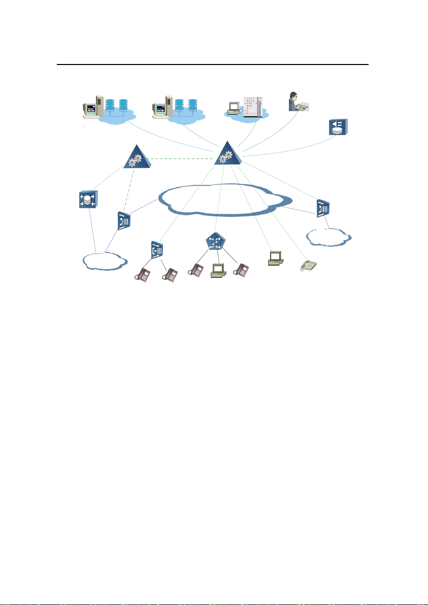
IAD108 is located in the user access level of NGN, as shown in
Figure 1-2.
1-2
Page 27
User Manual
H.323GK
MRS
3rd Party Server
SoftSwitch
Ephone
PCphone
SIP multimedia
terminal
MGCP/H.248
AMG5000
MGCP/H.248
AAA
SCP
PSTN
IP network
TMG
SoftSwitch
IAD108
PSTN
TMG
SG
R
R
U-SYS IAD108 Integrated Access Device Chapter 1 System Overview
AAA: Authentication,
Authorization and Accounting
SG: Signaling Gateway
SCP: Service Control
Point
TMG: Trunk Media
Gateway
MRS: Media Resource
Server
AMG: Access Media
Gateway
Figure 1-2 Location of IAD108 in NGN
1.2 Service Functions
provide abundant services:
Acting as a device in the user access layer of NGN, IAD108 can
Access POTS users to IP network.
z
Access Ethernet users into IP packet network.
z
Support IP semi-permanent connection (SPC) and internal
z
SPC.
Support T.38 fax or transparent transmission of fax.
z
Support transparent transmission of Modem signals.
z
1-3
Page 28

User Manual
U-SYS IAD108 Integrated Access Device Chapter 1 System Overview
Test on subscriber line. (optional)
z
Support the power supply from remote place.
z
Support traditional PSTN telephone services, including:
z
call forwarding, Caller Identification Display (CID) and call
waiting. With the right telephone set, voice message
indicator function can also be provided.
Support the supplementary services in coordination with a
z
softswitch.
Support intelligent services and special applications in
z
coordination with a softswitch.
1.3 System Structure
1.3.1 Hardware Structure
There are indicators on the front panel of IAD108, and their
names and meanings are as shown in Table 1-2.
Table 1-2 Table of IAD108 indicators
Indicator Color Name Meaning
When local power supply is
connected, it is on. If there is no
PWR Green
Power supply
indicator
power supply, it is off.
When remote power supply is
connected, it blinks. If there is no
power supply, it is off.
It blinks two times per second when
RUN Green
Running
indicator
loading.
It blinks one time per second when
running normally.
1-4
Page 29
User Manual
U-SYS IAD108 Integrated Access Device Chapter 1 System Overview
Indicator Color Name Meaning
Indicator for
WAN Green
uplink
interface
1–8 Green
Indicator for
telephone user
When the unplink interface is
normal, it is on, and if no network
cable is inserted, it is off.
When the user on the
corresponding interface off-hooks, it
is lighted up.
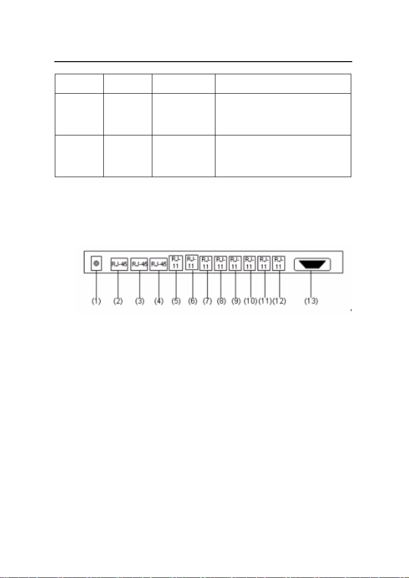
The external interfaces provided by IAD108 are located on the
back panel as shown in Figure 1-3.
(1) Local power supply interface (2) Upstream interface (3), (4) Data user interface
(5)–(12) POTS ports (13) Local maintenance serial port
Figure 1-3 External interface of IAD108
1.3.2 Software Structure
The software system of IAD108 consists of the main CPU
software and DSP software of the CSP. As the core of IAD, the main
CPU software implements the call control of the whole system,
management and maintenance function and forwarding of media
flow. The DSP software mainly implements the coding and decoding
of voice, detection and generation of Dual-tone Multifrequency
1-5
Page 30
User Manual
Service
access
module
SPC processing module
TDM/DSP
TDM/DSP
VoIP service processing module
Protocol processing module
MGCP/H248
Bottom layer drive module
POTS
Management, maintenance and operation module
U-SYS IAD108 Integrated Access Device Chapter 1 System Overview
(DTMF)/ Frequency Shift Keying (FSK), Voice Activity Detection
(VAD) and Comfort Noise Generation (CNG).
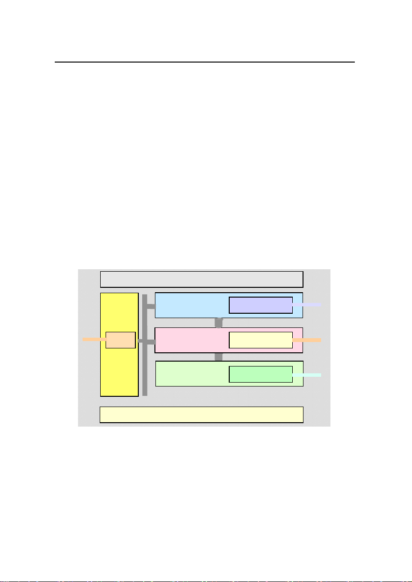
In terms of software structure, IAD108 consists of the following
functionality modules.
Management, maintenance and operation system module
z
Service access module
z
SPC service processing module
z
VoIP service processing module
z
Protocol processing module
z
Bottom layer drive module
z
The relations among the modules are shown in Figure 1-4.
Figure 1-4 Functionality modules of IAD108
The functions of these modules are listed in Table 1-3.
1-6
Page 31

User Manual
U-SYS IAD108 Integrated Access Device Chapter 1 System Overview
Table 1-3 Functions of modules in IAD108
Module Function
Management, maintenance
and operation module
It is responsible for maintenance, operation and
management of the whole IAD108 system.
It implements the selection, summary and report of
Service access module
analog user and digital user information, and
transmits the messages issued by the service
module.
SPC service processing
module
It establishes and maintains the SPCs between the
different users in the same IAD108, or different
users in different IAD108s.
It controls the interaction of user signalings and the
VoIP service processing
module
Time Division Multiplexing (TDM)/ Digital Signal
Processing (DSP) user module, and implements
the interconnection with the Media Gateway
Controller (MGC).
Protocol processing
module
It implements the processing of MGCP/H248
protocol stack and the adaptation of protocols.
Bottom layer drive module It drives various function chips on the CSP.
1-7
Page 32

User Manual
U-SYS IAD108 Integrated Access Device Chapter 2 Installing Hardware
Chapter 2 Installing Hardware
IAD108 consists of hardware system and software system.
Before running the equipment, you must install the hardware and
load the software.
2.1 Installation Requirements
2.1.1 Attentions in Installation
To avoid the damaged to equipment or the hurt to human body
caused by improper operation, you should pay attention to the items
listed in Table 2-1.
Table 2-1 Attentions in installation
Item Description
1
2
3
4
5
Do not put the equipment beside water or in damp place, in order to
prevent water and moisture from entering the equipment.
Do not put the equipment on precarious box or desk, in case it falls, it
will be seriously damaged.
Make sure that the working voltage is the same as the rated voltage,
because IAD108 can only work normally at proper voltage.
Never open the shell when the device is working. Do not open the shell,
even if it is powered off, unless absolutely necessary.
Before cleaning IAD108, pull out the power plug of the device. Wipe
IAD108 with dry cloths, and do not wash IAD108 with any liquid.
2-1
Page 33

User Manual
U-SYS IAD108 Integrated Access Device Chapter 2 Installing Hardware
2.1.2 Requirements for Installation Environment
IAD108 must be installed indoors. No matter it is installed in the
corridor or put on the desktop, the following conditions must be
guaranteed.
Make sure that enough spaces are reserved for the inlet
z
and outlet of IAD108 to facilitate heat dissipation.
Make sure that the corridor and the desktop is well
z
ventilated.
The working temperature of IAD108 is -5 to 50 degrees
z
Celsius, and the environmental humidity is 10%–90%.
2.1.3 Requirements for Electromagnetic Environment
IAD108 may be influenced by external electromagnetic signals
in radiation mode or conductive mode during its operation. Therefore,
you should pay attention to the points listed in Table 2-2.
Table 2-2 Measures for preventing electromagnetic interference
Item Description
AC power receptacles should be monophase three-wire receptacles with
1
protection grounding (PE). So that the filtration circuit on the equipment
can effectively filter the interference from electricity power supply.
2
3
The work site of the equipment should be far from powerful radio station,
radar station, or devices with high-frequency or huge-current.
If necessary, Electromagnetic masking method can be adopted, such as
adopting making cables for interface cables.
2-2
Page 34

User Manual
U-SYS IAD108 Integrated Access Device Chapter 2 Installing Hardware
Item Description
The interface cables must be wired indoors, and wiring them outdoors is
4
prohibited, because the overvoltage and over-currrent caused by
lightning will damage the signal interface.
2.1.4 Tools and Meters
The following meters and tools should be ready before the
installation work is started:
Table 2-3 List of tools and meters
Universal
Fastening
tools
Cross screwdriver M3
tools
Fitter tools Sharp-nose pliers, diagonal pliers, pliers
Special
tools
Meters
cable peeler, crimping pliers, and wire punch-down tool
Multimeters, 500V megaohm meters (for measuring the insulation
resistance)
Note:
z
The supplier should provide the list of tools and meters, and decide the provider
of the tools and meters together with the customer.
z
The meters must be calibrated and proved to be qualified before they can be
used.
2-3
Page 35

User Manual
U-SYS IAD108 Integrated Access Device Chapter 2 Installing Hardware
2.2 Installing Hardware
IAD108 is a box-like device with fixed configuration. Installation
on site is very simple, and the main installation steps are connections
of cables, as shown in Table 2-4
Table 2-4 Steps for installing hardware
Steps Operation
1 Fixing IAD108 box onto the specified location.
2 Connecting serial port cable (optional).
3 Connecting upstream cable.
4 Connecting user side cable
5 Connecting power cable
2.2.1 Putting IAD108 on Desktop
Put IAD108 on a clean desktop. Such installation is very simple,
and you should pay attention to the following:
Make sure that the desktop is stable.
z
Keep 10cm spaces around IAD108 for heat dissipation.
z
Do not put heavy objects over IAD108.
z
2.2.2 Connecting Serial Port Cable
The serial port of IAD108 is the female DCE (Data
Circuit-terminal Equipment) RS-232 port, as shown in Figure 2-1.
2-4
Page 36

User Manual
U-SYS IAD108 Integrated Access Device Chapter 2 Installing Hardware
Figure 2-1 Serial port of IAD108
The serial port is on the right part of the device’s rear panel. It is
labeled as CONSOLE. Features of serial port are: transmission rate
of 9600 bit/s, without parity check, 8 data bits, one stop bit, without
traffic control.
The signals tranceived by pinouts are as shown in Table 2-5,
and other unlisted pinouts are not used.
Table 2-5 Pingouts of the connector on console
Pingout Signal Sourcing from
2 TXD (transmit data ) DCE
3 RXD (receive data)
DTE (Data Terminal
Equipment)
5 Grounding of signal
IAD108 is connected with the maintenance terminal via a serial
port cable. The delivered serial port cable can connect DB-9 male
connector to DB-9 female connector. If the serial port on the
maintenance terminal is not a DB-9 male connector, you should
prepare the serial port cable by yourself.
The steps for connecting the serial port cable are as follows:
2-5
Page 37

User Manual
U-SYS IAD108 Integrated Access Device Chapter 2 Installing Hardware
1) Connect female end of the serial port cable to the DB-9
male connector on the PC or terminal that will configure the
IAD108.
2) Connect the DB-9 male connector of the serial port cable to
the configuration port of IAD108.
2.2.3 Connecting Uplink Cable
Due to different uplink modes, IAD108 has three models:
IAD108A, IAD108E and IAD108V correspond to ADSL uplink,
Ethernet uplink and VDSL uplink. The cable connections of them are
introduced. The connection methods for ADSL cable and VDSL
cable are the same and will be introduced together.
I.
IAD108E
IAD108E provides one channel of Fast Ethernet (FE) uplink,
and the uplink cable is a straight-through cable, which consists of two
RJ-45 connectors and a piece of category 5 cable. The appearance
of straight-through cable is as shown in Figure 2-2.
(1)
(2)
(3)
(2)
(1)
(1): Crystal connector (2): Protection sheath (3): Category 5 cable
Figure 2-2 Connection of network cable
2-6
Page 38

User Manual
U-SYS IAD108 Integrated Access Device Chapter 2 Installing Hardware
The structure of straight-through cable is as shown in Figure
2-3.
Figure 2-3 Structure of straight-through cable
The cable connections in straight-through cable are listed in
Table 2-6.
Table 2-6 Cable connections in straight-through cable
Connector
8-core category 5
twisted pair cable
Pin 1 White (orange) Pin 1
Pin 2 Orange Pin 2
Pin 3 White (green) Pin 3
Pin 4 Blue Pin 4
Pin 5 White (blue) Pin 5
Pin 6 Green Pin 6
Pin 7 White (brown) Pin 7
Pin 8 Brown Pin 8
2-7
Connector
Page 39

User Manual
U-SYS IAD108 Integrated Access Device Chapter 2 Installing Hardware
IAD108E uses a straight-through cable to connect the upper
network device. The connection steps are as follows:
1) Insert one end of the network cable into the uplink interface
(the RJ-45 interface close to the power interface) on the
back panel of IAD108E. Align the strip to the gap on the
interface and insert the RJ-45 connector. If a “click” is
heard, the connector is well plugged.
2) Connect the other end of the network cable to the uplink
network device according to actual situations.
II.
IAD108A/IAD108V
IAD108A/IAD108V provides one channel of ADSL/VDSL uplink,
and the uplink interface is the RJ-45 port beside the power interface.
ADSL/VDSL cable is an ordinary telephone line. The connection
steps are as follows:
1) Insert the RJ-11 connector of the telephone line into the
uplink RJ-45 interface on the IAD108A/IAD108V.
2) Connect the other end of the telephone line to the uplink
Digital Subscriber Line Access Multiplexer (DSLAM)
device.
2.2.4 Connecting the Cable on User Side
There are two kinds of subscriber cables: RJ-11 telephone line
and RJ-45 straight-through cable. They are used to connect different
types of subscriber interfaces. The correlation between the
subscriber interfaces and cables are as follows:
POTS port: There are eight POTS ports on the rear panel,
z
which can be connected with RJ-11 telephone line.
2-8
Page 40

User Manual
U-SYS IAD108 Integrated Access Device Chapter 2 Installing Hardware
Network interface: There are two downlink interfaces,
z
which can be connected with straight-through cables.
I.
Connecting Ordinary Telehphone Cables
Insert one end of the cable into an RJ-11 user interface, and the
other end into the socket on the telephone set.
II.
Connecting Straight-through Network Cable
1) Insert one end of the network cable into the downstream
RJ-45 interface on the back panel of IAD108. Align the strip
to the gap on the interface and insert the RJ-45 connector.
If a “click” is heard, the connector is well plugged.
2) Insert the other end of the network cable into the interface
on the network adapter of the PC. If the LINK indicators on
both IAD108 and the PC are lighted, it means the network
cable is correctly connected.
2.2.5 Connecting Power Cable
Usually, IAD108 adopts local 12V power as working power. If
IAD108 uplinks via FE, and the upper device (like LAN Switch)
supports remote power supply, IAD108 can also be powered by
remote power supply, that means the IAD108 is powered by the
upper device.
2-9
Page 41

User Manual
U-SYS IAD108 Integrated Access Device Chapter 2 Installing Hardware
Caution:
It is recommended that IAD108E mainly uses local power supply and the remote
power supply can be taken as emergency power supply.
To ensure safe operation, you must power on IAD108 after all the other cables have
been installed and the installation check has been passed.
I.
Connecting Local Power Supply
The local power supply of IAD208 is provided by the AC-DC
adapter.
The input voltage range is AC 100–240V, input current is 1.0A,
and input frequency is 50-60Hz. The DC output voltage is 12V, the
peak output current is 3A, and the peak power is 36W.
Steps for connecting power cables
1) Check whether all the serial port cable, uplink cable and
user cable have been correctly connected. If yes, the
equipment can be powered on.
2) Insert the output end of AC-DC power cable into the power
socket on the back panel of IAD108, and the other end into
the external AC power socket.
3) Check whether the power indicator (PWR) on the front
panel is normal. When the local power supply is used, the
PWR indicator on the front panel is lighted.
2-10
Page 42

User Manual
U-SYS IAD108 Integrated Access Device Chapter 2 Installing Hardware
Note:
It is recommended to use the monophase three-wire receptacles or multipurpose
receptacles for PCs. The neutral pole of the power supply must be grounded reliably
in the building. Generally, the neutral point of the power supply in a building should
have already been grounded. However, remember to confirm this before you install
IAD108.
II.
Connecting Remote Power Supply
Remote power supply can power IAD108E through its uplink
cable. IAD108E uses straight-through cable to uplink, and for the
details of straight-through cable, refer to section 2.2.3 I. of this
chapter.
When the remote power supply is correctly connected, the PWR
indicator will flash at the frequency of 4 Hz.
2-11
Page 43

User Manual
U-SYS IAD108 Integrated Access Device Chapter 3 Loading Software
Chapter 3 Loading Software
This chapter introduces how to load software after the hardware
has been correctly installed.
For IAD108, loading means to write the programs and data files
that are needed by the normal running of equipment into Flash
memory, so as to ensure the system can be upgraded and run
normally.
3.1 Setting up Configuration Environment for Loading
IAD108 can be loaded with software through local serial port or
Telnet mode.
3.1.1 Setting up Configuration Environment for Loading through Local Serial Port
You can use the HyperTerminal software of Windows
98/2000/NT/XP to implement maintenance through the local serial
port.
The connection between local serial port and the maintenance
terminal (PC) is as shown in Figure 3-1. The serial port cable should
already be connected when you are installing hardware. Refer to
Chapter 2.
3-1
Page 44

User Manual
IAD108
Maintenance terminal
Serial port cable
Console port of IAD108
Serial port of PC
U-SYS IAD108 Integrated Access Device Chapter 3 Loading Software
Figure 3-1 Connection for configuring through local serial port
The following is an example to connect and configure the local
serial port terminal, which is an ordinary PC running Window98
operating system.
1) On the maintenance terminal, click
[Start/Programs/Accessories/Communication/HyperTermi
nal], and then double click the “HyperTerminal” icon to start
the HyperTerminal.
2) Input the name in the “Connection Description” dialog box
like “IAD”, and click <OK> to establish the corresponding
serial port connection, as shown in Figure 3-2. Then click
<OK>.
3-2
Page 45

User Manual
U-SYS IAD108 Integrated Access Device Chapter 3 Loading Software
Figure 3-2 Set up a HyperTerminal connection
3) In the “Connect using” text box, select the actually used
serial port number, like “Com1”, as shown in Figure 3-3.
Then click <OK>.
3-3
Page 46

User Manual
U-SYS IAD108 Integrated Access Device Chapter 3 Loading Software
Figure 3-3 Select the serial port number
4) Set the parameters of serial port: baud rate as 9600 bit/s (it
must be consistent with that configured on IAD108 serial
port, and the default value is 9600 bit/s), data bit as 8, 1
stop bit, without parity check and flow control. The settings
are shown in Figure 3-4.
3-4
Page 47

User Manual
U-SYS IAD108 Integrated Access Device Chapter 3 Loading Software
Figure 3-4 Set the properties for COM 1
5) Select the [File/Properties/Settings] menu in the
HyperTerminal window, and set the Telnet terminal and
emulation types as "ANSI" and "Auto Detect". Refer to
Figure 3-5.
3-5
Page 48

User Manual
U-SYS IAD108 Integrated Access Device Chapter 3 Loading Software
Figure 3-5 Set the properties of IAD108
6) Click the <ASCII Setup> button, set the "Line delay" and
"Character delay" of the "ASCII sending" as 50ms, as
shown in Figure 3-6.
3-6
Page 49

User Manual
U-SYS IAD108 Integrated Access Device Chapter 3 Loading Software
Figure 3-6 Set ASCII
Note:
"Character delay" controls the display speed of each character when the
HyperTerminal shows text contents. "Line delay" controls the display time interval
between two lines.
When the delay is too short, it may result in character loss. So if the display is
abnormal, you should check the two values, and make modification if necessary.
3-7
Page 50

User Manual
Router
WAN
LAN
Local host running Telnet program
Router
IAD108
U-SYS IAD108 Integrated Access Device Chapter 3 Loading Software
7) After setting up the HyperTerminal, press <Enter> and the
welcome interface of IAD108 will be shown on the terminal.
Input the user name and password, then you can log in the
equipment to operate and maintain the equipment.
3.1.2 Setting up the Environment for Loading through Telnet
To remotely load software through Telnet, ensure that IP
attributes (like IP address, subnet mask, default gateway) of IAD108
have been correctly configured through local serial port.
The networking for maintaining IAD108 through Telnet is as
shown in Figure 3-7.
Figure 3-7 Set up Telnet connection for remote loading through a WAN
3-8
Page 51

User Manual
U-SYS IAD108 Integrated Access Device Chapter 3 Loading Software
Configuration steps are as follows.
1) Run Telnet program on the maintenance terminal, set its
terminal type as VT-100/ANSI and the buffer size as 1000,
as shown in Figure 3-8.
Figure 3-8 Set Telnet terminal preferences
Note:
The default Telnet buffer size is small, and you can increase the buffer size properly
so that more history commands can be displayed on the screen. Recommended
buffer size is 1000 lines.
2) Enter the IP address “172.21.100.16” of IAD108 on the
maintenance terminal, and then establish the connection.
3) After connecting IAD108, input correct user name and
password to log in the equipment to load software or
configure data.
3-9
Page 52

User Manual
U-SYS IAD108 Integrated Access Device Chapter 3 Loading Software
Note:
z
When you are configuring IAD108 through Telnet, do not randomly change the
IP address of IAD108. If it is necessary to modify the IP address, after the
modification, the Telnet connection will be disconnected and you must log in
again with the new IP address to establish the connection.
z
The system allows 4 Telnet users to log in concurrently. If it prompts that there
are too many users, you should wait and log in latter.
3.2 Updating Software
The loading of software can be made through Trivial File
Transfer Protocol (TFTP) or File Transfer Protocol (FTP). If the IAD is
not directly connected with the server which stores the load files,
FTP mode is recommended, because the FTP transmission has
higher reliability.
3.2.1 Configuring TFTP Server
When TFTP is used to update IAD108 software, the new
software is downloaded through network interface. To do this, a PC is
used as the file server to run TFTP server program.
Specific methods for configuring TFTP server.
1) Establish the TFTP server environment
First, take a PC as the TFTP server. Connect the TFTP server
and IAD108 through network interfaces, and configure the IP
address of TFTP server so that the two can ping each other.
3-10
Page 53

User Manual
U-SYS IAD108 Integrated Access Device Chapter 3 Loading Software
2) Run TFTP program.
Note:
In this manual, TFTPD32 is taken as an example to demonstrate how to configure
the TFTP server on this computer. The installation program of TFTP server is not
delivered with the equipment, and you must get it by yourself.
Run TFTP program “TFTPD32”, and the interface after startup
is as shown in Figure 3-9.
Figure 3-9 Interface of TFTP program
3-11
Page 54

User Manual
U-SYS IAD108 Integrated Access Device Chapter 3 Loading Software
3) Click <Settings> to set the storage directory for the file to
be loaded. In the “Base Directory” text box, input the
storage directory “C:\IAD108V2R2” for the software to be
loaded and other items take default values, as shown in
Figure 3-10.
Figure 3-10 Set the storage directory for the software to be loaded
4) After select the directory of the files to be loaded, click
<OK> to finish the settings of TFTP server.
3-12
Page 55

User Manual
U-SYS IAD108 Integrated Access Device Chapter 3 Loading Software
3.2.2 Configuring FTP Server
When FTP is used to update IAD108 software, the new
software is downloaded through network interface. To do this, a PC is
used as the file server to run FTP server program.
Specific methods for configuring FTP server.
1) On IAD108, configure the user name and password for
logging in to FTP server.
For instance, set the user name and password as "IAD” and
“108”.
IAD2000>enable
IAD2000#configure terminal
IAD2000(config)#ftpserver iad 108
{ <cr>|dirname<S><1,80> }:
Command:
ftpserver iad 108
Begin to save ftp server infomation, please wait a
minutes...
ftp server login username : iad
ftp server login password : 108
ftp server directory name : .
IAD2000(config)#
2) Establish FTP server environment.
Configure the IP address of FTP server. Connect the FTP
server and IAD108 through network interfaces. Make sure that the
FTP server can ping IAD108.
3) Run the FTP server program.
3-13
Page 56

User Manual
U-SYS IAD108 Integrated Access Device Chapter 3 Loading Software
Note:
In this manual, Serv-U is taken as an example to demonstrate how to configure FTP
server on this PC. The installation program of FTP server is not delivered with the
equipment, and you must get it by yourself.
Run the FTP program ”Serv-U” to enter the setting interface of
FTP server as shown in Figure 3-11.
Figure 3-11 Start interface of FTP program
4) Set login user name and password for Serv-U to log in to
IAD108.
In the menu of Figure 3-11, select [Setup/Users…] to enter the
user management interface and add a user.
3-14
Page 57

User Manual
U-SYS IAD108 Integrated Access Device Chapter 3 Loading Software
Input the user name and password that have been
preconfigured on IAD108. For example, set the user name as “IAD”
and password as “108”. Then select the storage directory for the files
to be loaded on this PC, as shown in Figure 3-12.
After confirming that all the above information is correct, click
<Store> to save the newly added user.
Figure 3-12 Add a new user
5) Set the authorities for accessing a file/directory
In the interface shown in Figure 3-12, click the <Add> below the
“File/Directory access rules” text box to pop up the dialog box as
3-15
Page 58

User Manual
U-SYS IAD108 Integrated Access Device Chapter 3 Loading Software
shown in Figure 3-13. Click <Browse> to select the storage directory
for the files to be loaded, such as “C:\iad108v2r2”.
Then click <OK> to return to the interface as shown in Figure
3-14. At this time, the authority for accessing “C:\iad108v2r2” has
been added into the “Path” text box.
Figure 3-13 Select the directory of the files to be loaded
3-16
Page 59

User Manual
U-SYS IAD108 Integrated Access Device Chapter 3 Loading Software
Figure 3-14 Set the authority for accessing a file/directory
Click the <OK> in the right lower corner of Figure 3-14 to finish
the setting of Serv-U.
3.3 Loading Software
There are two modes for loading software: BIOS mode and host
mode.
3.3.1 BIOS Mode
BIOS mode can only be used for local loading, and cannot be
used for remote loading. The loading procedures are as follows.
3-17
Page 60

User Manual
U-SYS IAD108 Integrated Access Device Chapter 3 Loading Software
1) Connect the serial ports of maintenance terminal and
IAD108 through a serial port cable, and then turn on the
HyperTerminal.
2) Reboot the system (through command reboot), and the
following interface will be displayed.
IAD2000>enable
IAD2000#configure terminal
IAD2000(config)#reboot
The config data has been changed, config will be lost
if reboot, continue? [Y|N]:y
Are you sure to reset system? [Y|N]:y
System will reboot in 5 seconds!
Press 't' to Test SDRAM :
Starting...
Init LAN switch ok.
******************************************************
*
HUAWEI IAD2000 SYSTEM BOOT
Copyright 2002-2005 Huawei Technology. Co.,
Ltd.
******************************************************
*
BIOS version: 503
Creation date: Jun 8 2004, 16:38:15
auto-booting...
3-18
Page 61

User Manual
U-SYS IAD108 Integrated Access Device Chapter 3 Loading Software
Attaching network interface lo0... done.
Attached TCP/IP interface to cpm0.
setting basic net para... done.
Please press CTRL+B to enter bootmenu,other key to boot!
remain 3s
3) In the above interface, press <Ctrl+B> within five seconds
to enter the BIOS menu. If the boot program cannot find the
applicable host program, DSP program and voice file in the
Flash memory, it will enter BIOS interface automatically.
Welcome to bootmenu!
User name (<=20 chars):manager
User password (<=20 chars):
4) The system will prompt you to input user name and
password. (Default user name and password are
“manager” and “manager”). After inputting them, you can
enter BIOS menu.
=======================
BOOT MENU
=======================
1.Enter equipment test
2.Enter download submenu
3.Show download zone information
4.Boot system from flash
5.Modify bootrom password
R.Reset
3-19
Page 62

User Manual
U-SYS IAD108 Integrated Access Device Chapter 3 Loading Software
Enter your choice(1-6 or R):
Items in the menu are listed in Table 3-1. Except 1 and 2, other
items have no submenus.
Table 3-1 Meanings of the menu items in IAD108 BIOS
Menu Meaning
1. Enter equipment test Enter equipment test
2. Enter download submenu Enter loading status
3. Show download zone information
Display the information of the file areas in
the Flash memory
4. Boot system from flash Start the system to enter the host program
5. Modify bootrom password Modify the BIOS password
6. R.Reset Reset the system
5) Select 2 to enter the following menu.
=======================
FILE DOWNLOAD SUBMENU
=======================
1. Enter serial submenu
2. Enter ethernet submenu
R. Return upper menu
Enter your choice(1-2 or R):
3-20
Page 63

User Manual
U-SYS IAD108 Integrated Access Device Chapter 3 Loading Software
Selecting “1”, you will enter serial port loading menu. Selecting
“2”, you will enter network interface loading menu. Selecting “R”, you
can return the upper level menu.
6) Select to load through serial port or network interface. In
the following part, 1 and 2 are parallel, and you can only
choose one to enter step 7.
In the above menu, select “1” to enter serial port loading
z
menu:
=======================
SERIAL SUBMENU
=======================
1. Download file to Flash through serial interface
2. Show serial parameter
3. Set serial parameter
R. Return to file download submenu
Enter your choice(1-3 or R):
Selecting 2 indicates to show the serial port parameter.
Selecting 3 indicates to set the serial port parameter, (here only the
baud rate can be modified). Selecting R means to return to the upper
level menu.
In the upper level menu, select 2 to enter the network
z
interface loading submenu.
=======================
FTP SUBMENU
=======================
1. Download file to Flash through ethernet interface
3-21
Page 64

User Manual
U-SYS IAD108 Integrated Access Device Chapter 3 Loading Software
2. Show ethernet interface parameter
3. Modify ethernet interface parameter
4. Show FTP download parameter
5. Modify FTP download parameter
R. Return to file download submenu
Enter your choice(1-5 or R):
Selecting 2 indicates to show the parameter settings of the
network interface, such as the IP address. Selecting 3 means to
modify the IP address and subnet mask. Selecting 4 indicates to
show the FTP parameter setting (i.e., the IP address, password, user
name and the file to be loaded of the FTP server. Selecting 5 means
to modify the FTP parameter setting. Selecting R means to return to
the upper level menu.
7) Selecting 1 to enter file loading selection menu.
=======================
FILE SELECT SUBMENU
=======================
1. Download IAD program to flash
2. Download local language file to flash
3. Download gen language file to flash
4. Download BIOS to flash
5. Download VOICE file to flash
6. Download DSP program to flash
7. Download SLIC file to flash
8. Download CPLD file to flash
9. Download packet file to flash
A. Download xDSL file to flash
3-22
Page 65

User Manual
U-SYS IAD108 Integrated Access Device Chapter 3 Loading Software
R. Return to upper menu
Enter your choice(1-9 or R):
The meanings of the menu items are listed in Table 3-2.
Table 3-2 Meanings of BIOS file loading menu items
Item Description
1. Download IAD program to flash Load host program
2. Download local language file to flash Load local language file
3. Download gen language file to flash Load universal language file
4. Download BIOS file to flash Load BIOS file
5. Download VOICE file to flash Load voice file
6. Download DSP program to flash Load DSP program
7. Download SLIC file to flash Load SLIC file
8. Download CPLD file to flash Load logic file
9. Download packet file to flash Load file package
A. Download xDSL file to flash Load xDSL file
R. Return to upper menu Return to upper level menu
Note:
In the serial port loading selecting menu or the network interface loading selecting
menu, if you select 1 you will enter the file loading selecting menu.
3-23
Page 66

User Manual
U-SYS IAD108 Integrated Access Device Chapter 3 Loading Software
In the above menu, item 9 is very special: When BIOS selects 9
in the menu to load packet file, it will take all the files out of the packet
(packet file consists of iad_voice and ida_dsp) to update the
corresponding files in the Flash memory. So it is flexible. Loading
and upgrading of a single file can be completed through other menu
items.
8) Select the file and loading it.
According to the selection in step 6, the loading can be
implemented through network interface and serial port. The following
part describes these two modes.
If you select network interface loading in step 6:
z
If the FTP server is correctly configured and the uplink interface
of IAD108 can ping through FTP server, you can do it.
For the configuration of FTP server, refer to section 3.2.2 .
If you select serial port loading in step 6:
z
When the above items are selected, you must transmit the
corresponding files through the HyperTerminal within the default time
allowed by the system.
3-24
Page 67

User Manual
U-SYS IAD108 Integrated Access Device Chapter 3 Loading Software
Note:
z
You can enter the “FILE SELECT SUBMENU” menu by clicking “SERIAL
SUBMENU”/”1. Download file to Flash through serial interface”, or “FTP
SUBMENU”/”1. Download file to Flash through Ethernet interface”.
z
The operations made after you entering “FILE SELECT SUBMENU” through
“SERIAL SUBMENU” is different from those after entering through "FTP
SUBMENU”. If you enter through “SERIAL SUBMENU”, you need to perform
file transmission. If you enter through “FTP SUBMENU”, you can directly load
the file to the Flash memory.
After entering the “FILE SELECT SUBMENU” menu through
“SERIAL SUBMENU”/”1. Download file to Flash through serial
interface”, select load file “9”. The interface is displayed as follows:
=======================
FILE SELECT SUBMENU
=======================
1. Download IAD program to flash
2. Download local language file to flash
3. Download gen language file to flash
4. Download BIOS to flash
5. Download VOICE file to flash
6. Download DSP program to flash
7. Download SLIC file to flash
8. Download CPLD file to flash
9. Download packet file to flash
A. Download xDSL file to flash
3-25
Page 68

User Manual
U-SYS IAD108 Integrated Access Device Chapter 3 Loading Software
R. Return to upper menu
Enter your choice(1-9 or R):9
============================================
Down load file by xmodem_crc protocol.... CCCCCC
When the above prompt appears on the terminal, select
[Transfer/Send File] in the HyperTerminal window, then select the file
to be loaded, set the transmission protocol as Xmodem, and click
<Send>.
When IAD108 and HyperTerminal are correctly connected, and
the file transmission starts, the transmission progress will be shown
on HyperTerminal.
When the loading succeeds, the following prompt will appear
and the system will return to the menu interface of selecting loading
file.
Down load file by xmodem_crc protocol end
===========================================
Download file successful.
Check file CRC value... done.
Copy file (voice resource) to flash(0x10300000),please
wait...... Done.
Save file end.
The file of you download check successful, and copy to
flash ok!
=======================
FILE SELECT SUBMENU
3-26
Page 69

User Manual
U-SYS IAD108 Integrated Access Device Chapter 3 Loading Software
=======================
1. Download IAD program to flash
2. Download local language file to flash
3. Download gen language file to flash
4. Download BIOS to flash
5. Download VOICE file to flash
6. Download DSP program to flash
7. Download SLIC file to flash
8. Download CPLD file to flash
9. Download packet file to flash
A. Download xDSL file to flash
R. Return to upper menu
Enter your choice(1-9 or R):
If you select to go on loading other files, the above loading
process will be repeated.
9) When all the files have been loaded, you need to select “R”
in the submenus to return to the BootMenu. In the main
menu, you can select Reset to restart the system to enter
the interface of main program.
3-27
Page 70

User Manual
U-SYS IAD108 Integrated Access Device Chapter 3 Loading Software
Note:
z
When the serial port loading is implemented, the system will be restarted. The
rate of serial port will be automatically restored to 9600 bit/s. If the
HyperTerminal does not display normally, you should adjust the attributes of the
HyperTerminal and change the baud rate to 9600 bit/s.
z
When loading through serial port, generally the transmission rate is slow. You
can accelerate the loading rate through command line, and the highest rate is
115200 bit/s.
3.3.2 Command Line Loading Mode
IAD108 can also be loaded in command line mode. In this mode,
you can only load the package file iad_packet. It contains the four
files needed for upgrading IAD108: iad_voice, iad_dsp, iad_prog.lzw,
and iad_bios. Based on different transmission modes, there are
three modes: Xmodem protocol mode, FTP mode, and TFTP mode.
When Xmodem protocol mode is used, you can only transmit
files through serial port. This mode is suitable for local loading.
However, its transmission speed is very low. In FTP/TFTP mode, the
network interface is used to transmit the files. It is used in both
remote loading and local loading. In remote loading, as FTP is more
reliable than TFTP, FTP is recommended.
3-28
Page 71

User Manual
U-SYS IAD108 Integrated Access Device Chapter 3 Loading Software
I.
Loading File Through Xmodem Protocol
1) Connect the serial ports of maintenance terminal and
IAD108 through a serial port cable, and establish the
HyperTerminal connection.
2) On the HyperTerminal, enter command load and press
<Enter>.
Example: Load package file through Xmodem protocol.
IAD2000#load system dsp xmodem
IAD2000(config)#load packet xmodem
Load(backup) begins. This process will take several
minutes. If it is interrupted unproperly, it will fail.
Please wait and check the result.
Besides, you can use command 'show progress load' to
display the progress information.
Please select "Send file"sub menu of "Send" main menu
to send file...
CCCCCCCCCCCCCCCCCCCCCCCCCCCCCCCCCC
3) Select [Transfer/Send File] on HyperTerminal. The
protocol type should be "Xmodem". After select the files to
be sent, click <Send>. After the loading begins, the
transmission progress will be shown on the terminal.
3-29
Page 72

User Manual
U-SYS IAD108 Integrated Access Device Chapter 3 Loading Software
Note:
z
When loading files through the serial port by using Xmodem protocol, it takes a
long time. Please wait patiently, and do not reboot the system.
z
To speed up the loading speed, you can use command baudrate to set the
communication rate to 115200 bit/s, and set the communication rate of console
to 115200 bit/s too. Otherwise, the communication will fail.
z
During the rebooting of the system after the loading is finished, the serial port
speed will be automatically recovered to 9600 bit/s.
4) After the files are completely sent, the following information
will be displayed.
IAD2000#
OPERATION TYPE: Load operation
FILE TYPE: Packet file
OPERATION STAGE: save file
PROCESS: 92%
OPERATION TYPE: Load operation
FILE TYPE: Packet file
OPERATION RESULT: Operation complete
FAILURE REASON: Vacancy
IAD2000#
5) If you need to load other files, repeat steps 2 and 3. The
loaded file can only take effect after the system is rebooted.
To reboot the system, you can execute the command
reboot in privilege mode.
3-30
Page 73

User Manual
U-SYS IAD108 Integrated Access Device Chapter 3 Loading Software
Example: In privilege mode, input command reboot to reboot
the system.
IAD2000#reboot
The config data has been changed, config will be lost
if reboot, continue? [Y|N]:y
Are you sure to reset system? [Y|N]:y
System will reboot in 5 seconds!
II.
Loading File Through TFTP/FTP
1) In local loading, connect the serial ports of the
maintenance terminal and IAD108 through a serial port
cable, and then turn on the HyperTerminal. In remote
loading, use Telnet program to log in to the device.
2) Connect the IAD108 with the FTP server/TFTP server
through a network cable. Make sure that the server can
ping the IAD108. For the settings of FTP server/TFTP
server, refer to section 3.2.1. The IP address of the IAD108
can be check through command show ip address, or be
modified through command ip address.
3) Run the FTP program or TFTP program on the file server.
4) To start the FTP server program, you need to set the
following items on the maintenance terminal: user name
and password used to log in to the FTP server, and path of
the file to be loaded. If you use TFTP to load, the latter
operation is unnecessary.
IAD2000(config)#ftpserver iad 108
C:\WINDOWS\Desktop\IAD108V2R2
Begin to save ftp server infomation, please wait a
minutes...
3-31
Page 74

User Manual
U-SYS IAD108 Integrated Access Device Chapter 3 Loading Software
ftp server login username : iad
ftp server login password : 108
ftp server directory name :
C:\WINDOWS\Desktop\IAD108V2R2
Note:
z
In the above command, “IAD108” is a legal user name in the FTP server, the
password is “passwd”, and the path of the file to be loaded is “C:\IAD108
B01D030”. Such settings must be consistent with those set in FTP Serv-U.
z
To use FTP for loading, first execute command ftpserver. After that, carry out
command write to save the configurations in command ftpserver to the device.
After that, when the device is loaded through FTP in next rebooting, the
command ftpserver needs not be carried out.
z
Format of command ftpserver: ftpserver username password [dirname]. In this
command, username and password are the name and password used to log in
to the FTP server, and dirname is the directory name of FTP server. This
command is used in global config mode.
5) On the maintenance terminal, enter command load packet
to load the package file. During the loading, you can use
command show progress load to check the loading
progress.
IAD2000(config)#load packet ftp 172.21.50.51 iad_packet
Load(backup) begins. This process will take several
minutes. If it is interrupted unproperly, it will fail.
Please wait and check the result.
Besides, you can use command 'show progress load' to
3-32
Page 75

User Manual
U-SYS IAD108 Integrated Access Device Chapter 3 Loading Software
display the progress information.
IAD2000(config)#
OPERATION TYPE: Load operation
FILE TYPE: Packet file
OPERATION STAGE: file is transmitted into board from
outside
PROCESS: 10%
OPERATION TYPE: Load operation
FILE TYPE: Packet file
OPERATION STAGE: file is transmitted into board from
outside
PROCESS: 85%
OPERATION TYPE: Load operation
FILE TYPE: Packet file
OPERATION STAGE: save file
PROCESS: 1%
OPERATION TYPE: Load operation
FILE TYPE: Packet file
OPERATION STAGE: save file
PROCESS: 80%
OPERATION TYPE: Load operation
FILE TYPE: Packet file
OPERATION RESULT: Operation complete
FAILURE REASON: Vacancy
3-33
Page 76

User Manual
U-SYS IAD108 Integrated Access Device Chapter 3 Loading Software
IAD2000(config)#
6) To load other files, repeat step 4. After all the programs
loaded, use command reboot to reset the system and
make the new programs valid. Before rebooting, make
sure that the formerly configured data has been saved
through command write.
3-34
Page 77

User Manual
U-SYS IAD108 Integrated Access Device Chapter 4 Configuring Data
Chapter 4 Configuring Data
In this chapter, the methods and steps for configuring IAD108
data through command line are introduced.
4.1 Preparations Before Configuration
Before configuring IAD108, you should prepare the basic data
of this IAD108 and know the user name and password used for
logging into the device.
4.1.1 Collecting Data
Before configuring data, you must plan the data of IAD108, such
as IP address of IAD108, and IP address of the related servers.
Since IAD108 interworks with Media Gateway Controller (MGC), you
should also plan the data for the interconnection between them.
The IP addresses need to be planned are listed in Table 4-1.
Table 4-1 IP address allocation table
No. Item Remarks
1 IP address of IAD108 None.
2
3 IP address of MGC
IP address of the default gateway for
IAD108’s uplink
4-1
LAN Switch or low end
router
In this manual, SoftSwitch
is taken as an example of
MGC.
Page 78

User Manual
U-SYS IAD108 Integrated Access Device Chapter 4 Configuring Data
No. Item Remarks
Loghost is the host used for
4 IP address of Loghost
generating and storing
logs.
NMS is the network
5
IP address of Network Management
Station (NMS)
management station that
runs IAD Management
System (IADMS).
6
7
IP address of Domain Name server
(DNS)
IP address of Simple Network Time
Protocol (SNTP) server
DNS is the Domain Name
server.
”SNTP” indicates the
Simple Network Time
Protocol server.
Note:
In the above table, the IP addresses of NMS, DNS, SNTP, and Loghost are not
mandatory. If IAD108 is not configured with the server, the corresponding IP
address will be unnecessary.
Table 4-2 Parameters for interconnection with MGC
Data need to be configured on
MGC
Data need to be configured on IAD108
IP address of IAD108 IP address of MGC
Port number of User Datagram
Protocol (UDP)
Port number of transfer layer protocol
Type of control protocol Type of control protocol
4-2
Page 79

User Manual
U-SYS IAD108 Integrated Access Device Chapter 4 Configuring Data
Data need to be configured on
MGC
Data need to be configured on IAD108
Encoding type Encoding type
Type of transfer protocol Type of transfer protocol
Domain name of IAD108 Domain name of IAD108
Interface name of IAD108 Interface name of IAD108 (local name)
Domain name of MGC Domain name of MGC
4.1.2 Login Environment
After the system is loaded and rebooted, the following interface
will appear.
IAD2000#reboot
The config data has been changed, config will be lost
if reboot, continue? [Y|N]:y
Are you sure to reset system? [Y|N]:y
System will reboot in 5 seconds!
Press 't' to Test SDRAM :
Starting...
Init LAN switch ok.
******************************************************
*******************
HUAWEI IAD2000 SYSTEM BOOT
Copyright 2002-2005 Huawei Technology. Co.,
4-3
Page 80

User Manual
U-SYS IAD108 Integrated Access Device Chapter 4 Configuring Data
Ltd.
******************************************************
*******************
BIOS version: 506
Creation date: Jul 12 2004, 10:16:22
auto-booting...
Attaching network interface lo0... done.
Attached TCP/IP interface to cpm0.
setting basic net para... done.
Please press CTRL+B to enter bootmenu,other key to boot!
remain 0s
According to the prompt, you can press any key to go to the next
step, or wait for 5 seconds and the system will automatically enter
the next step. You can press <CTRL+B> to enter the BIOS interface
to operate. Refer to section 3.2.1 in Chapter 3.
Begin to check program area in flash... done..
Copy program from area(1) to ram!
Expand file to
ram ......................................
......................................................
.
......................................................
.
......................................................
4-4
Page 81

User Manual
U-SYS IAD108 Integrated Access Device Chapter 4 Configuring Data
.
......................................................
.
......................................................
.
......................................................
.
Starting at 0x10000...
Init LAN switch ok.Attached TCP/IP interface to cpm unit
0
Attaching network interface lo0... done.
NFS client support not included.
setting basic net para... done.
No record in exception buffer!
Initialize and check system config data... done.
Start Initialize SPI.
DSP Initialize Succeed .
SPI module initialized OK.
MIB initialization OK!
wait agent ...
Begin Register to IADMS
1 ............................................
4-5
Page 82

User Manual
U-SYS IAD108 Integrated Access Device Chapter 4 Configuring Data
Time out when registering to IADMS 1
Searching modification on system config data while
initializing...
Nothing modified.
When the device has been started successfully, the following
interface will pop up to prompt you to input user name and password.
By default, IAD108 has a super manager, whose user name is “root”
and password is “admin”. Note that the password is case sensitive,
while the user name is not. Here, take the super manager as an
example, enter the user name “root” and password “admin” (it is not
displayed on the screen). The following prompt will appear.
User name (<=15 chars):root
User password (<=15 chars):
IAD2000>
When the prompt “IAD2000>” appears on the screen, it means
that you have logged into the system successfully.
After logging into the system for the first time, you must modify
the login password of the super manager. The command user
password in privilege mode is used to modify the password. Note
that the password is case-sensitive and the maximum length is 15
characters.
Caution:
If the super manager “root” forgets the password, contact the technical support
engineer of Huawei.
4-6
Page 83

User Manual
U-SYS IAD108 Integrated Access Device Chapter 4 Configuring Data
Example: Enter global config mode to modify the password of
user “root“.
IAD2000>enable
IAD2000#configure terminal
IAD2000(config)#user password
User Name(<=15 chars):root
Old Password(<=15 chars):
New Password(<=15 chars):
Confirm Password(<=15 chars):
Changed ok!
Continue? [Y|N]:n
IAD2000(config)#
When the system prompts “Continue? [Y|N]”, if you want to
modify the passwords of other users, you can input “Y” to go on.
Otherwise, you can input “N” and press <Enter>. The system default
value is “N”.
Note:
For the commands related to the management of users, you can refer to Section
5.1.3 of Chapter 5.
4.2 Basic Commands
A command prompt of IAD108 consists of two parts: fixed
character string + command mode identifier. The command mode
identifier indicates the mode in which the current command is in. For
4-7
Page 84

User Manual
U-SYS IAD108 Integrated Access Device Chapter 4 Configuring Data
example: “>” indicates that the command mode is user mode, while #
indicates privilege mode. In the global config mode, you can use the
command hostname to configure the fixed character string. By
default, the fixed character string of the system is “IAD2000”.
Example: Modify the default host name of the system into
“IAD108”.
IAD2000(config)#hostname IAD108
To change command line prompt is ok
IAD108(config)#
This command is executed successfully, and the host name has
been changed into “IAD108”.
4.2.1 Command Modes
IAD108 has the following command modes: User mode,
privilege mode, global config mode, advanced mode, debug mode,
and LAN switch mode. During data configuration, commands are
frequently used to switch over the command modes and save the
data.
Note:
It is unusual to use the commands in advance mode and debug mode to configure
and maintain the device, therefore, only the features and usage of some usually
used commands are introduced in this manual.
The commands used in advance mode and debug mode can be found in Appendix
A.
4-8
Page 85

User Manual
U-SYS IAD108 Integrated Access Device Chapter 4 Configuring Data
The privilege mode and global config mode are compatible with
the lower-authority modes.
In the privilege mode, you can run the commands in the
z
user mode.
In the global config mode, you can run all the commands in
z
the user mode and privilege mode.
The relations among the command modes are shown in Figure
4-1. The oval circles in the figure represent different command
modes, each arrow indicates the change from one mode to another
mode. The mode change commands are appended to the arrows.
Figure 4-1 Relations among different command modes
Example: To switch from privilege mode to global config mode,
carry out command configure terminal. To exit from global config
mode to privilege mode, carry oute command exit.
4-9
Page 86

User Manual
U-SYS IAD108 Integrated Access Device Chapter 4 Configuring Data
4.2.2 Usually Use Commands
The usually used commands and their functions are listed in
Table 4-3.
Table 4-3 List of usually used commands
Command Function
IAD2000>enable Enter the privilege mode
IAD2000#configure terminal
IAD2000(lanswitch)# configure
terminal
Enter the global config mode
IAD2000# lanswitch
Enter the LAN Switch mode
IAD2000(config)#lanswitch
Disable (any mode)
Exit from current mode and enter the
user mode
Exit from current mode and enter the
Exit (any mode)
previous mode, or exit from the
configuration environment
language (any mode) Modify current language mode
Write (any mode) Save data immediately
IAD2000>cls Clear the screen
IAD2000>show version Show the version of the equipment
IAD2000(config)#user password Modify user name and password
4-10
Page 87

User Manual
U-SYS IAD108 Integrated Access Device Chapter 4 Configuring Data
Caution:
To prevent data loss caused by system rebooting or power-off, you can execute
command write in privilege mode to save the configured data.
4.2.3 Examples
I.
Entering Global Config Mode from Privilege Mode:
IAD2000#configure terminal
IAD2000(config)#
II.
Modifying Current Language Mode
IAD2000(config)#language
The current language mode has been switched.
IAD2000(config)#
III.
Saving Data
IAD2000(config)#write
Command executing, please wait...
System starts to save configuration data, please wait a
moment......
The configuration data backup percent is: 100%
IAD2000(config)#
IV.
Showing Version of Equipment
IAD2000#show version
4-11
Page 88

User Manual
U-SYS IAD108 Integrated Access Device Chapter 4 Configuring Data
Equipment type : IAD108
Main Board PCB version : AG21CSPA VER.A
Software version : IAD2000V200R002B01D031
BIOS version : 506
SLIC version : (U35-U38)015
CPLD version : (U16)100
DSP version : (U34)V100R1C1B23D10
IAD2000#
4.3 Process of Data Configuration
The configuration of basic data is the basis for other
configurations. Only when the correctness and validity checks of the
basic data have been implemented, can you configure interface data,
access user data, protocol data and software parameters.
Table 4-4 shows the configuration procedures.
Table 4-4 Data configuration process of IAD108
Steps Operation
Step 1 Configure basic data of the equipment
Step 2 Configure voice user data
Step 3 Configure MG attribute data
Step 4 Configure protocol data (optional)
Step 5 Configure software parameter (optional)
After you have finished the configuration of a group of data, you
can run the command show running-config in privilege mode to
4-12
Page 89

User Manual
U-SYS IAD108 Integrated Access Device Chapter 4 Configuring Data
check the correctness of the configured data. If you want to check
the initial configuration of the system, you can execute command
show startup-config in the privilege mode.
Note:
z
Except that the first step is mandatory, other steps are parallel without strict
sequence.
z
Steps 4 and 5 are optional because the system has default values.
4.4 Configuring Basic Data of the Equipment
Configuration of equipment basic data include: Information of
this device, IP address, time, and the configurations of all the related
servers. The IP address is most important and must be configured,
while other data can be configured optionally according to the actual
conditions.
Although there is no strict requirement on sequence, it is
recommended to configure the data according to the sequence listed
in Table 4-5.
4.4.1 Task List
4-13
Page 90

User Manual
U-SYS IAD108 Integrated Access Device Chapter 4 Configuring Data
Note:
The configuration tasks are arranged from the very beginning of your configuration
procedures.
Table 4-5 Task list of configuring equipment data
Serial No. Operation Command
1
Configure data of
this device
banner incoming hostname phone
Configure fixed IP address:
ip address ip-address net-mask gateway-ip
Configure the system to obtain IP address
automatically:
Configure IP
2
address of IAD108
(mandatory)
dhcp enable
Configure PPPoE to obtain IP address
automatically:
pppoe username usermane password
password
pppoe { disable | enable }
Set the system time of IAD108 to be
synchronous with SNTP server:
3
Set the system time
of IAD108
sntp server {address server-ip | name
server-name}
sntp time-zone sign value
sntp interval interval-seconds
4-14
Page 91

User Manual
U-SYS IAD108 Integrated Access Device Chapter 4 Configuring Data
Serial No. Operation Command
Set system time of IAD108:
clock set hh:mm:ss yyyy-mm-dd
Configure the
4
domain name and
IP address of DNS
dns domain-name name
dns server first { second | third }
Configuring device ID:
eid eid
5 Add an NMS
Configure IADMS information:
iadms adms-num nmsaddress
getcommunity setcommunity trapcommunity
[ nmsTrapPort ]
4.4.2 Configuring the Data of This Equipment
When you log in to the IAD108 from the serial port or from a
Telnet connection, you will see some welcome messages, including
the name of the device, and the contact telephone number. You can
set or change these messages with the command banner incoming
hostname phone
in global config mode
.
4-15
Page 92

User Manual
U-SYS IAD108 Integrated Access Device Chapter 4 Configuring Data
Note:
hostname is used to identify the device in the network and can be configured
randomly.
In usual cases, it is configured according to the customer’s requirements. If there is
no requirements, it is recommended to name it in the following format:
Hostname = office name + MG type
*office name = country + city + location + operator name
Example: Configure an IAD for Huawei:
z
Hostname: SZ-BT-HW-IAD108
z
IAD2000#configure terminal
IAD2000(config)#banner incoming
Please input location name(<20 chars): SZ-BT-HW-IAD108
Please input phone number(example:010-88888888):
0755-12345678
Hostname config success
IAD2000(config)#write
Command executing, please wait...
System starts to save configuration data, please wait a
moment......
The configuration data backup percent is: 100%
: 0755-12345678.
phone
After configuration, log in the device again. The information of
this office configured just now will be shown in the prompt.
IAD2000(config)#reboot
Are you sure to reset system? [Y|N]:y
4-16
Page 93

User Manual
U-SYS IAD108 Integrated Access Device Chapter 4 Configuring Data
System will reboot in 5 seconds!
Press 't' to Test SDRAM :
Starting...
Init LAN switch ok.
******************************************************
*
HUAWEI IAD2000 SYSTEM BOOT
Copyright 2002-2005 Huawei Technology. Co.,
Ltd.
******************************************************
*
BIOS version: 506
Creation date: Jul 12 2004, 10:16:22
auto-booting...
Attaching network interface lo0... done.
Attached TCP/IP interface to cpm0.
setting basic net para... done.
Please press CTRL+B to enter bootmenu,other key to boot!
remain 0s
Begin to check program area in flash... done..
Copy program from area(1) to ram!
Expand file to
4-17
Page 94

User Manual
U-SYS IAD108 Integrated Access Device Chapter 4 Configuring Data
ram ......................................
......................................................
.
......................................................
.
......................................................
.
......................................................
.
......................................................
.
......................................................
.
Starting at 0x10000...
Init LAN switch ok.Attached TCP/IP interface to cpm unit
0
Attaching network interface lo0... done.
NFS client support not included.
setting basic net para... done.
No record in exception buffer!
Initialize and check system config data... done.
Start Initialize SPI.
DSP Initialize Succeed .
4-18
Page 95

User Manual
U-SYS IAD108 Integrated Access Device Chapter 4 Configuring Data
SPI module initialized OK.
MIB initialization OK!
Searching modification on system config data while
initializing...
Nothing modified.
******************************************
* *
* IAD2000 Integrated Access Device *
* *
******************************************
Copyright 2002-2005 Huawei Technology. Co., Ltd.
Location Name: SZ-BT-HW-IAD108
Phone Number: 0755-12345678
4.4.3 Configuring IP Address of IAD108
IP address is an important parameter of IAD108, and it must be
configured. After being configured, the IP address can take effect
immediately without rebooting. The IP address of IAD108 can be got
in three ways:
Configure fixed IP address
z
Dynamically obtained from the DHCP server
z
Obtained through PPPoE dialup mode
z
You can use the command show ip address in user mode to
check the IP address of IAD108.
IAD2000>show ip address
--------------------------------------------------
ip address : 172.21.100.16
4-19
Page 96

User Manual
U-SYS IAD108 Integrated Access Device Chapter 4 Configuring Data
subnetwork mask: 255.255.0.0
default gateway: 172.21.200.250
MAC address : 00-E0-FC-1E-24-88
PPPoE disable
vlan tag function is disable
vlan id : 0
vlan priority : 3
DHCP function is disable
TOS of voice packets: Maxmize reliability
TOS of other packets: Normal service
--------------------------------------------------
IAD2000>
I.
Configuring Fixed IP Address for IAD108
In global config mode, you can use the following command to
configure the fixed IP address for IAD108.
ip address ip-address net-mask gateway-ip
ip-address, net-mask
: IP address and subnet mask of IAD108.
Example: Configure the fixed IP address of IAD108 as
“172.21.100.16”, and subnet mask as “255.255.0.0”, while default
gateway as “172.21.200.250”.
IAD2000(config)#ip address 172.21.100.16 255.255.0.0
172.21.200.250
Changing net parameter may affect current service,
continue?[Y|N]:y
Command executing, please wait...
--------------------------------------------------
4-20
Page 97

User Manual
U-SYS IAD108 Integrated Access Device Chapter 4 Configuring Data
ip address : 172.21.100.16
subnetwork mask: 255.255.0.0
default gateway: 172.21.200.250
--------------------------------------------------
IAD2000(config)#
II.
Configuring IAD108 to Obtain IP Address Through DHCP
To dynamically obtain the IP address, IAD108 needs to
cooperate with DHCP server, and the DHCP server in the network
must work and communicate with IAD108 normally.
When configuring data for IAD108, you can execute command
dhcp enable to start the DHCP client. The commands are listed in
Table 4-6.
Table 4-6 Commands used to obtain IP address dynamically
Operation Command
Prohibit DHCP IAD2000(config)#dhcp disable
Refresh IP address IAD2000(config)#dhcp renew
Example: Configure IAD108 to dynamically obtain the IP
address through DHCP.
1) Check the current configuration of IAD108 before
configuring it.
IAD2000(config)#show ip address
--------------------------------------------------
ip address : 172.21.100.16
subnetwork mask: 255.255.0.0
4-21
Page 98

User Manual
U-SYS IAD108 Integrated Access Device Chapter 4 Configuring Data
default gateway: 172.21.200.250
MAC address : 00-E0-FC-1E-24-88
PPPoE disable
vlan tag function is disable
vlan id : 0
vlan priority : 3
DHCP function is disable
TOS of voice packets: Maxmize reliability
TOS of other packets: Normal service
--------------------------------------------------
IAD2000(config)#
2) The result shows that the DHCP function is prohibited
currently. Start the DHCP function.
IAD2000(config)#dhcp enable
Changing net parameter may affect current service,
continue?[Y|N]:y
Command executing, please wait...
--------------------------------------------------
ip address : 172.21.50.79
subnetwork mask: 255.255.0.0
default gateway: 172.21.200.250
--------------------------------------------------
IAD2000(config)#
3) The command has been executed successfully, and check
the IP address again.
IAD2000(config)#show ip address
--------------------------------------------------
ip address : 172.21.50.79
subnetwork mask: 255.255.0.0
4-22
Page 99

User Manual
U-SYS IAD108 Integrated Access Device Chapter 4 Configuring Data
default gateway: 172.21.200.250
MAC address : 00-E0-FC-1E-24-88
PPPoE disable
vlan tag function is disable
vlan id : 0
vlan priority : 3
DHCP function is enable
TOS of voice packets: Maxmize reliability
TOS of other packets: Normal service
--------------------------------------------------
IAD2000(config)#
4) The result shows that the DHCP function has been started,
and the IP address “172.21.50.79” is obtained from the
DHCP server.
III.
Configuring IAD108 to Obtain IP Address Through
PPPoE Dialup
IAD108 supports PPPoE dialup mode. It can obtain IP address
from the DNS server during the PPPoE dialup process and perform
DNS resolution.
Configuration for PPPoE can be made in two steps:
1) Configure user name and password
2) Enable PPPoE
If PPPoE dialup fails, the system will automatically dial up again.
The commands are listed in Table 4-8.
4-23
Page 100

User Manual
U-SYS IAD108 Integrated Access Device Chapter 4 Configuring Data
Table 4-7 Commands for IAD108 to obtain IP address through PPPoE dialup
Operation Command
Configure PPPoE user name
and password
IAD2000(config)#pppoe username usermane
password password
Enable PPPoE IAD2000(config)#pppoe { disable | enable }
Show PPPoE configuration IAD2000>show pppoe
username
: PPPoE user name, a character string ranging 1–31
characters.
password: PPPoE user password, a character string ranging
1–31 characters.
The user name and password are used on the broadband
access server (BAS) for authenticating the user. They must be
consistent with those configured on the BAS.
Example: Configure IAD108 to obtain IP address through
PPPoE dialup mode. The operations are as follows.
3) Set the PPPoE user name as “zw@isp”, and password as
“huawei”.
IAD2000(config)#pppoe username zw@isp password huawei
IAD2000(config)#
4) Start PPPoE function
IAD2000(config)#pppoe enable
IAD2000(config)#
5) Check PPPoE configurations
IAD2000(config)#show pppoe
--------------------------------------------------
4-24
 Loading...