

Page 1

HUAWEI TE40&TE50&TE60 Videoconferencing
Endpoint
V100R001C10
Administrator Guide
Issue 01
Date 2014-12-23
HUAWEI TECHNOLOGIES CO., LTD.
Page 2

Proprietary and Confidential
Copyright © Huawei Technologies Co., Ltd. 2014. All rights reserved.
No part of this document may be reproduced or transmitted in any form or by any means without prior
written consent of Huawei Technologies Co., Ltd.
Trademarks and Permissions
and other Huawei trademarks are trademarks of Huawei Technologies Co., Ltd.
All other trademarks and trade names mentioned in this document are the property of their respective
holders.
Notice
The purchased products, services and features are stipulated by the contract made between Huawei and
the customer. All or part of the products, services and features described in this document may not be
within the purchase scope or the usage scope. Unless otherwise specified in the contract, all statements,
information, and recommendations in this document are provided "AS IS" without warranties, guarantees or
representations of any kind, either express or implied.
The information in this document is subject to change without notice. Every effort has been made in the
preparation of this document to ensure accuracy of the contents, but all statements, information, and
recommendations in this document do not constitute a warranty of any kind, express or implied.
Huawei Technologies Co., Ltd.
Address: Huawei Industrial Base
Bantian, Longgang
Shenzhen 518129
People's Republic of China
Website: http://enterprise.huawei.com
Issue 01 (2014-12-23)
Huawei
Copyright © Huawei Technologies Co., Ltd.
i
Page 3
HUAWEI TE40&TE50&TE60 Videoconferencing
Proprietary and Confidential
Endpoint
Administrator Guide About This Document
About This Document
Before you use the product, refer to the product vendor for version mapping information and
to confirm compatibility with other videoconferencing equipment.
This document describes how to use the HUAWEI TE40 Videoconferencing Endpoint (TE40
or endpoint for short), HUAWEI TE50 Videoconferencing Endpoint (TE50 or endpoint for
short), and HUAWEI TE60 Videoconferencing Endpoint (TE60 or endpoint for short),
including conference experience, device control, address book management, system settings,
installation, maintenance, and troubleshooting.
Intended Audience
This document is intended for but not limited to endpoint administrators.
An endpoint administrator has access to all functions on the endpoint web interface, touch
panel (optional), and remote controlled user interface (UI). It is recommended that endpoint
administrators set parameters and manage the address book on the endpoint web interface.
When using this document, note the following:
Unless otherwise specified, the descriptions in this document are applicable to the TE40,
TE50, and TE60.
Except chapters 7.7 Security and 9.4 Customizing the Remote Controlled UI which
apply to the endpoint user interface controlled by the remote control (remote controlled
UI for short), descriptions and configurations in this document apply to the endpoint web
interface.
Symbol Conventions
The symbols that may be found in this document are defined as follows.
Symbol Description
Indicates an imminently hazardous situation which, if not
avoided, will result in death or serious injury.
Issue 01 (2014-12-23) Huawei
Indicates a potentially hazardous situation which, if not
avoided, could result in death or serious injury.
ii
Copyright © Huawei Technologies Co., Ltd.
Page 4
HUAWEI TE40&TE50&TE60 Videoconferencing
Proprietary and Confidential
Endpoint
Administrator Guide About This Document
Symbol Description
Indicates a potentially hazardous situation which, if not
avoided, may result in minor or moderate injury.
Indicates a potentially hazardous situation which, if not
avoided, could result in equipment damage, data loss,
performance deterioration, or unanticipated results.
NOTICE is used to address practices not related to personal
injury.
Change History
Changes between document issues are cumulative. The latest document issue contains all the
changes made in earlier issues.
Issue 01 (2014-12-23)
This issue is the first official release.
Calls attention to important information, best practices and
tips.
NOTE is used to address information not related to personal
injury, equipment damage, and environment deterioration.
Issue 01 (2014-12-23) Huawei
iii
Copyright © Huawei Technologies Co., Ltd.
Page 5

HUAWEI TE40&TE50&TE60 Videoconferencing
Proprietary and Confidential
Endpoint
Administrator Guide Contents
Contents
About This Document ............................................................................................................... ii
1 Overview ................................................................................................................................... 1
1.1 Definition of an Endpoint Administrator ...................................................................................................................... 1
1.2 Requirements on an Administrator ............................................................................................................................... 2
1.3 Related Documentation................................................................................................................................................. 3
1.4 Safety Precautions ........................................................................................................................................................ 4
1.5 How to Obtain Help .................................................................................................................................................... 10
2 Web-based Login .................................................................................................................... 11
3 Menu Structure of the Web Interface .................................................................................. 14
4 Conference Experience .......................................................................................................... 16
4.1 Initiating a Point-to-Point Conference ........................................................................................................................ 17
4.1.1 Initiating a Conference from the Call Page .............................................................................................................. 17
4.1.2 Initiating a Conference from the Address Book ....................................................................................................... 18
4.1.3 Holding a Call .......................................................................................................................................................... 18
4.2 Initiating a Multipoint Conference.............................................................................................................................. 19
4.2.1 Understanding the MCU and Built-in MCU ............................................................................................................ 19
4.2.2 Initiating a Conference from the Predefined Conference Page ................................................................................ 22
4.2.3 Initiating a Conference from the Conference History Page ..................................................................................... 25
4.2.4 Initiating a Conference from the Address Book Page .............................................................................................. 25
4.3 Scheduling a Conference ............................................................................................................................................ 26
4.4 Joining a Conference Using the Conference Access Number ..................................................................................... 27
4.5 Joining an MSUC Convergent Conference ................................................................................................................. 28
4.6 Joining an HD-Video Conference over an IMS Network ........................................................................................... 30
4.7 Sharing a Presentation ................................................................................................................................................ 33
4.8 Creating and Sending Captions ................................................................................................................................... 34
4.9 Using the Do-Not-Disturb Function ........................................................................................................................... 35
4.10 Controlling a Conference .......................................................................................................................................... 35
4.11 Recording a Conference ............................................................................................................................................ 43
4.12 Sending and Receiving Instant Messages ................................................................................................................. 44
5 Device Control ........................................................................................................................ 46
5.1 Viewing the Video....................................................................................................................................................... 47
Issue 01 (2014-12-23) Huawei
iv
Copyright © Huawei Technologies Co., Ltd.
Page 6

HUAWEI TE40&TE50&TE60 Videoconferencing
Proprietary and Confidential
Endpoint
Administrator Guide Contents
5.2 Controlling a Camera .................................................................................................................................................. 48
5.3 Setting a Camera Preset .............................................................................................................................................. 49
5.4 Selecting Video Sources ............................................................................................................................................. 51
5.5 Controlling Audio ....................................................................................................................................................... 52
5.6 Setting the Combined Picture ..................................................................................................................................... 55
5.7 Setting Camera Parameters ......................................................................................................................................... 55
5.8 Setting Preferred Video Parameters ............................................................................................................................ 57
5.9 Setting Up a PPPoE Dial-Up Connection ................................................................................................................... 58
5.10 Using the Remote Control ........................................................................................................................................ 59
6 Managing the Local Address Book ...................................................................................... 60
6.1 Editing the Local Address Book ................................................................................................................................. 60
6.2 Using Virtual Conference Rooms ............................................................................................................................... 63
6.3 Importing and Exporting Address Book .................................................................................................................. 64
6.4 Customizing a Site Template ...................................................................................................................................... 64
7 System Settings ...................................................................................................................... 66
7.1 Setting Basic Parameters ............................................................................................................................................ 67
7.1.1 Setting the System time ........................................................................................................................................... 67
7.1.2 Setting the Ringtone for Incoming Calls ................................................................................................................. 68
7.1.3 Managing Power ...................................................................................................................................................... 68
7.1.4 Setting Number Key Functions ................................................................................................................................ 70
7.2 Specifying Caption Settings ........................................................................................................................................ 70
7.3 Setting Video Parameters ............................................................................................................................................ 72
7.3.1 Understanding Video Input Capabilities .................................................................................................................. 72
7.3.2 Configuring Video Input .......................................................................................................................................... 75
7.3.3 Setting the Multi-View Mode .................................................................................................................................. 77
7.3.4 Understanding Video Output Capabilities ............................................................................................................... 78
7.3.5 Configuring Video Output ....................................................................................................................................... 81
7.4 Configuring Audio ...................................................................................................................................................... 88
7.5 Specifying Conference Settings .................................................................................................................................. 90
7.5.1 Setting Audio and Video Protocols .......................................................................................................................... 90
7.5.2 Setting General Conference Parameters .................................................................................................................. 90
7.5.3 Setting Advanced Conference Parameters ............................................................................................................... 94
7.6 Specifying Network Settings ...................................................................................................................................... 98
7.6.1 Setting IP Parameters ............................................................................................................................................... 98
7.6.2 Setting H.323 Parameters ...................................................................................................................................... 103
7.6.3 Setting SIP Parameters ........................................................................................................................................... 105
7.6.4 Setting Wi-Fi Parameters ....................................................................................................................................... 108
7.6.5 Setting SNMP Parameters ...................................................................................................................................... 111
7.6.6 Setting Network Address Book Parameters ........................................................................................................... 114
7.6.7 Setting Firewall Parameters ................................................................................................................................... 117
7.6.8 Setting Network Diagnostics Parameters ............................................................................................................... 119
Issue 01 (2014-12-23) Huawei
v
Copyright © Huawei Technologies Co., Ltd.
Page 7

HUAWEI TE40&TE50&TE60 Videoconferencing
Proprietary and Confidential
Endpoint
Administrator Guide Contents
7.6.9 Setting QoS Parameters ......................................................................................................................................... 120
7.6.10 Connecting to a 4E1 Network .............................................................................................................................. 122
7.6.11 Connecting to a PSTN Network ........................................................................................................................... 126
7.7 Security ..................................................................................................................................................................... 126
7.7.1 Enabling Encryption .............................................................................................................................................. 126
7.7.2 Supporting Remote Logins .................................................................................................................................... 127
7.7.3 Setting the Password of the Remote Control Administrator .................................................................................. 128
7.7.4 Setting the Upgrade Password ............................................................................................................................... 129
7.7.5 Setting the Air Content Sharing Password ............................................................................................................. 129
7.7.6 Setting Web Account Security ............................................................................................................................... 130
7.7.7 Setting Whitelist .................................................................................................................................................... 131
7.8 Importing Security Certificates ................................................................................................................................. 132
7.8.1 Importing a Certificate ........................................................................................................................................... 132
7.8.2 Importing Web Certificates .................................................................................................................................... 133
7.8.3 Updating Web Certificates ..................................................................................................................................... 134
7.9 Managing System Files ............................................................................................................................................. 134
7.9.1 Importing and Exporting Settings .......................................................................................................................... 134
7.9.2 Backing Up Settings .............................................................................................................................................. 135
7.9.3 Importing License Files ......................................................................................................................................... 135
7.9.4 Importing a Layout Policy File .............................................................................................................................. 136
7.9.5 Creating and Downloading a CSR File .................................................................................................................. 137
8 Upgrading ............................................................................................................................. 138
8.1 Automatic Upgrade ................................................................................................................................................... 139
8.2 Tool Upgrade ............................................................................................................................................................ 140
8.3 Upgrading the Endpoint Using the Mini System ...................................................................................................... 143
8.4 Upgrading the Endpoint on Its Web Interface ........................................................................................................... 144
9 Maintenance .......................................................................................................................... 145
9.1 Checking the Working Environment Periodically .................................................................................................... 146
9.2 Managing Common Users and Passwords ................................................................................................................ 146
9.3 Customizing the Web Interface ................................................................................................................................. 147
9.4 Customizing the Remote Controlled UI ................................................................................................................... 149
9.4.1 Customizing Onscreen Status Icons ....................................................................................................................... 149
9.4.2 Customizing the Home Screen............................................................................................................................... 149
9.4.3 Customizing Conference Control Functions to Be Displayed ............................................................................... 151
9.4.4 Customizing the Option Bar .................................................................................................................................. 151
9.5 Checking the Endpoint Periodically ......................................................................................................................... 152
9.6 Viewing System Status ............................................................................................................................................. 152
9.7 Querying System Information................................................................................................................................... 153
9.8 Querying Logs .......................................................................................................................................................... 153
9.9 Restoring Your Endpoint to Default Settings ............................................................................................................ 154
10 Troubleshooting ................................................................................................................. 155
Issue 01 (2014-12-23) Huawei
vi
Copyright © Huawei Technologies Co., Ltd.
Page 8

HUAWEI TE40&TE50&TE60 Videoconferencing
Proprietary and Confidential
Endpoint
Administrator Guide Contents
10.1 Understanding Diagnosis Methods ......................................................................................................................... 155
10.2 Common Faults ....................................................................................................................................................... 159
11 Technical Specifications .................................................................................................... 171
11.1 Physical Specifications ........................................................................................................................................... 171
11.2 Performance and Capacity ...................................................................................................................................... 172
11.3 Ports and Protocols ................................................................................................................................................. 173
11.4 Standards Compliance............................................................................................................................................. 176
A E1 and T1 Grounding Criteria ........................................................................................... 178
B Menu Structure of the Remote Controlled UI ................................................................. 179
C Requirements on Room Layout and Lighting ................................................................. 181
D Status Icons .......................................................................................................................... 182
E Default Settings ................................................................................................................... 185
F Glossary ................................................................................................................................. 187
Issue 01 (2014-12-23) Huawei
vii
Copyright © Huawei Technologies Co., Ltd.
Page 9

HUAWEI TE40&TE50&TE60 Videoconferencing
Proprietary and Confidential
Endpoint
Administrator Guide 1 Overview
About This Chapter
This document guides you through configuring, managing, maintaining, and troubleshooting
the endpoint.
1.1 Definition of an Endpoint Administrator
An endpoint administrator is an enterprise employee who is responsible for managing and
maintaining endpoint operations.
1.2 Requirements on an Administrator
As an administrator, you must meet the following basic endpoint administrator proficiencies
and be capable of collecting all information related to the endpoint and its working
environment.
1.3 Related Documentation
This section lists the documentation that you may refer to when you perform routine
operations and maintenance as well as answering questions from standard users.
1.4 Safety Precautions
For safety purposes, carefully read through these safety precautions and observe them during
operation.
1
Overview
1.5 How to Obtain Help
When you encounter an endpoint issue, use the help on the endpoint web interface or contact
technical support personnel.
1.1 Definition of an Endpoint Administrator
An endpoint administrator is an enterprise employee who is responsible for managing and
maintaining endpoint operations.
An endpoint administrator has the following job responsibilities:
Configures and manages the endpoint.
Routinely maintains the endpoint.
Issue 01 (2014-12-23) Huawei
1
Copyright © Huawei Technologies Co., Ltd.
Page 10

HUAWEI TE40&TE50&TE60 Videoconferencing
Proprietary and Confidential
Endpoint
Administrator Guide 1 Overview
Troubleshoots the endpoint failures.
Answers standard users' questions about endpoint use.
1.2 Requirements on an Administrator
As an administrator, you must meet the following basic endpoint administrator proficiencies
and be capable of collecting all information related to the endpoint and its working
environment.
Basic Endpoint Administrator Proficiencies
Windows operating system
Gatekeeper (GK) and Session Initiation Protocol (SIP) servers
Ethernet, TCP/IP, and Client/Server (C/S) model
H.323 and SIP protocols
Safe and effective use of electronic devices
Common maintenance tools
Videoconferencing endpoint functions and services
Information About the Endpoint and Its Working Environment
Table 1-1 lists the endpoint and working environment information that must be collected,
which helps you fulfill your job responsibilities and check the preparations for a recovery
from an emergency.
Table 1-1 Information to be collected
Category No. Item Description
Device
information
1 Device location
2 Networking condition
3 Endpoint information List the IP address, user name,
Record the endpoint location in
as much detail as possible so
the endpoint can be quickly
located.
Record the network topology
and hardware connection
diagram that include every
device.
and password for the endpoint
so you can quickly log in to the
endpoint in case of an
emergency. If you are not
permitted to record the
password for security reasons,
memorize it.
Software
and tools
Issue 01 (2014-12-23) Huawei
4 Software versions and tools
Copyright © Huawei Technologies Co., Ltd.
List the software versions
corresponding to the endpoint.
Prepare troubleshooting tools.
2
Page 11

HUAWEI TE40&TE50&TE60 Videoconferencing
Proprietary and Confidential
Endpoint
Administrator Guide 1 Overview
Category No. Item Description
Contact
information
Spare parts 7 Spare parts
5
6
8 Redundant or temporary devices
Purchased parts' service
information
Technical support personnel's
contact information
1.3 Related Documentation
Record the manufacturer
contact information, serial
numbers, and manufacturers'
warranty clauses for purchased
parts.
Maintain a list of technical
support personnel with their
contact information and
responsibilities.
List all spare parts (including
the spare parts that Huawei can
provide) and corresponding
procurement methods.
List all redundant or temporary
devices in the system, such as
standby file servers and
database servers.
This section lists the documentation that you may refer to when you perform routine
operations and maintenance as well as answering questions from standard users.
You can refer to the documentation listed in Table 1-2.
Table 1-2 Reference documentation
Document Description When to Use How to Obtain
HUAWEI
TE40&TE50&TE60
Videoconferencing
Endpoint
V100R001C10
Quick Installation
Guide
HUAWEI
TE40&TE50&TE60
Videoconferencing
Endpoint
V100R001C10
Quick Installation
Guide
HUAWEI
TE40&TE50&TE60
Videoconferencing
Describes the
packaged items and
provides guidance
for quick
installation, and
common
configuration.
Describes the
remote controlled UI
and provides quick
instructions in
commonly-used
endpoint functions.
Describes how to
operate the endpoint.
When checking
whether the carton
contains all the
required items and
when installing the
endpoint
When answering
questions from
standard users who
are using the
endpoint for the first
time or unfamiliar
with the endpoint
When answering
standard users'
questions about
Hold Ctrl and click
the following
hyperlink: Product
Support > Unified
Communications
and
Collaboration >
Telepresence and
Videoconferencing
> Telepresence
Endpoints > Group
Endpoints.
Issue 01 (2014-12-23) Huawei
3
Copyright © Huawei Technologies Co., Ltd.
Page 12

HUAWEI TE40&TE50&TE60 Videoconferencing
Proprietary and Confidential
Endpoint
Administrator Guide 1 Overview
Document Description When to Use How to Obtain
Endpoint
V100R001C10 User
daily endpoint
operations
Guide
HUAWEI
TE40&TE50&TE60
Videoconferencing
Endpoint
V100R001C10
Administrator Guide
(this document)
HUAWEI
TE40&TE50&TE60
Videoconferencing
Endpoint
V100R001C10 Help
Describes
conference
experience, device
control, address
book management,
system settings,
upgrade,
maintenance, and
troubleshooting
based on the
endpoint web
interface.
Describes the
endpoint web
interface and
method for using
this interface.
When setting
parameters,
managing the
address book,
controlling
conferences,
upgrading the
endpoint, and
performing daily
maintenance.
When answering
questions that
standard users
encounter on the
endpoint web
interface or
explaining the
parameters on this
interface
Log in to the
endpoint web
interface and click
the Help tab.
1.4 Safety Precautions
For safety purposes, carefully read through these safety precautions and observe them during
operation.
Basic Precautions
Keep the device dry and secure from collision during storage, transportation, and
operation of the device.
Do not attempt to dismantle the device by yourself. In case of any fault, contact the
appointed maintenance center for assistance or repair.
Without prior written consent, no organization or individual is permitted to make any
change to the structure or safety and performance design of the device.
While using the device, observe all applicable laws, directives, and regulations, and
respect the legal rights of others.
Environmental Precautions
Place the device in a well-ventilated place. Do not expose the device to direct sunlight.
Install the device strictly according to the requirements of the manufacturer.
Issue 01 (2014-12-23) Huawei
Copyright © Huawei Technologies Co., Ltd.
4
Page 13

HUAWEI TE40&TE50&TE60 Videoconferencing
Proprietary and Confidential
Endpoint
Administrator Guide 1 Overview
Do not place any object on the top of the device. Reserve a minimum space of 10 cm at
the four sides of the device for heat dissipation.
Do not place the device on or near inflammable materials such as foam.
Keep the device away from heat source or fire, such as a radiator or a candle.
Keep the device away from any household appliances with strong electromagnetic fields,
such as a microwave oven, refrigerator, or mobile phone.
Operating Precautions
Do not allow children to play with the device or accessories. Swallowing the accessories
may be fatal.
Use the accessories such as the power adapter and battery provided or authorized only by
the manufacturer.
Ensure that the device does not get wet. If water gets into the device, disconnect the
power supply immediately and unplug all the cables connected to the device, including
the power cable, telephone cable, video cable, audio cable, network cable, and serial
cable, and then contact the appointed maintenance center.
Before plugging or unplugging any cable, shut down the device and disconnect the
power supply. While plugging or unplugging any cable, ensure that your hands are dry.
Do not step on, pull, or overbend any cable. Otherwise, the cable may be damaged,
leading to malfunction of the device.
Do not use old or damaged cables.
In lightning weather, disconnect the device from the power supply and unplug all the
cables connected to the device.
Keep the power plug clean and dry, to prevent electric shock or other dangers.
If the device is not used for a long time, disconnect the power supply and unplug the
power plug.
If smoke, sound, or smell is emitted from the device, stop using the device immediately,
disconnect the power supply, unplug the power plug and other cables, and remove the
batteries. Then, contact the appointed maintenance center for repair.
Ensure that no object (such as metal shavings) enters the device through the heat
dissipation vent.
Before connecting any other cable, connect the ground cable of the device. Do not
disconnect the ground cable until you have disconnected all the other cables.
Ensure that the three-phase power socket is grounded properly. The neutral line and the
live line cannot be connected inversely.
Do not scratch or abrade the shell of the device. The shed painting may lead to skin
allergy or malfunction of the device. If the shed painting material drops into the host, a
short circuit may occur.
Cleaning Precautions
Before cleaning the device, stop using it, disconnect the power supply, and unplug all the
cables connected to the device, including the power cable, telephone cable, video cable,
audio cable, network cable, and serial cable.
Do not clean the device shell with any cleaning solution or cleanser spray. Use a piece of
soft cloth to clean the device shell.
Issue 01 (2014-12-23) Huawei
5
Copyright © Huawei Technologies Co., Ltd.
Page 14

HUAWEI TE40&TE50&TE60 Videoconferencing
Proprietary and Confidential
Endpoint
Administrator Guide 1 Overview
Battery Usage Precautions of the Remote Control
Use only the recommended battery. Pay attention to the polarity of the batteries while
installing them.
If a battery does not fit in the device, do not apply force. Otherwise, the battery may leak
or explode.
To reduce the risk of explosion, do not use batteries of different types together. For
example, do not use an alkaline battery and a Mn-Zn battery together. It is recommended
that you use batteries provided or recommended by the manufacturer.
Do not use a new battery with an old battery. When you replace batteries, replace all of
them at the same time.
If you are not going to use the device for a long time, remove all the batteries.
If any battery leaks, emits smoke, or emits abnormal smell, stop using it immediately.
If the battery fluid comes in contact with your skin or clothes, rinse with water
immediately and seek medical assistance.
If the battery fluid goes into your eyes, do not rub your eyes. Rinse your eyes with water
immediately and seek medical assistance.
LCD Usage Precautions
Do not expose the LCD to direct sunlight.
Do not scratch or strike, apply force to, or place heavy objects on top of the LCD.
Do not watch the LCD screen for extended periods of time. This may harm your eyes or
blur your vision.
Touch Panel Usage Precautions
Do not tap the touch panel with excessive force.
Do not let the touch panel exposed to water or other liquids.
Place the touch panel on the desktop steadily to prevent it from falling.
LCD Cleaning Precautions
According to the instructions in the attached manual, use a piece of soft cloth to remove
dust from the surface of the LCD.
Do not clean the LCD with volatile solvents, such as alcohol, benzene, or a dilution
agent. Do not keep the LCD in contact with a rubber or plastic materials for long periods
of time. This will deteriorate the surface gloss of the LCD.
Wireless Product Usage Precautions
Keep the wireless device away from magnetic storage devices, such as a magnetic card
or a floppy disk to prevent loss of the stored information.
Stop using the wireless device and disconnect it from the power supply in places where
using of wireless devices is prohibited or using of a wireless device may lead to
interference or danger.
Unplug the wireless device from the endpoint and turn off the endpoint close to a
high-precision controlled electronic device, such as an audio phone, a pacemaker, fire
alarm, or an automatic gate. Otherwise, this will lead to malfunction of the electronic
device.
Issue 01 (2014-12-23) Huawei
6
Copyright © Huawei Technologies Co., Ltd.
Page 15

HUAWEI TE40&TE50&TE60 Videoconferencing
Proprietary and Confidential
Endpoint
Administrator Guide 1 Overview
The user who uses an electronic assistant medical-treatment device needs to confirm
with the service center regarding the effects of the radio wave on this device.
Do not take the wireless device to the operation theater, Intensive Care Unit (ICU), or the
Coronary Care Unit (CCU).
When using the device, ensure that the antenna of the device is at least 20 cm away from
all parts of your body.
In the area with inflammable or explosive materials, turn off your wireless device and
follow the relevant instructions given on the label to prevent an explosion or fire.
Use your wireless device and its accessories in a clean and dust-free environment.
Ensure that the wireless device does not come in contact with flame or a lit cigarette.
Ensure that the wireless device and its accessories are dry.
Do not drop, throw, or bend your wireless device.
Do not place the wireless device and its accessories in areas with extreme temperatures.
Reduction of Hazardous Substances
This device is compliant with the EU Registration, Evaluation, Authorization and Restriction
of Chemicals (REACH) Regulation (Regulation No 1907/2006/EC of the European
Parliament and of the Council) and the EU Restriction of Hazardous Substances (RoHS)
Directive (Directive 2002/95/EC of the European Parliament and of the Council). For more
information about the REACH compliance of the device, visit the website
www.huaweidevice.com/certification. You are recommended to visit the website regularly for
up-to-date information.
Statement on a Class A Product
This is a class A product. In a national environment this product may cause radio interference
in which case the user may be required to take adequate measures.
European Regulatory Compliance
The endpoint complies with the following European directives and regulations.
1999/5/EC (R&TTE)
2002/95/EC & 2011/65/EU (RoHS)
EC NO. 1907/2006 (REACH)
2002/96/EC (WEEE)
The endpoint complies with Directive 2002/95/EC, 2011/65/EU and other similar regulations
from the countries outside the European Union, on the RoHS in electrical and electronic
equipment. The endpoint does not contain lead, mercury, cadmium, and hexavalent chromium
and brominated flame retardants (Polybrominated Biphenyls (PBB) or Polybrominated
Diphenyl Ethers (PBDE)) except for those exempted applications allowed by RoHS directive
for technical reasons.
The endpoint complies with Regulation EC NO. 1907/2006 (REACH) and other similar
regulations from the countries outside the European Union. Huawei will notify to the
European Chemical Agency (ECHA) or the customer when necessary and regulation requires.
The endpoint complies with Directive 2002/96/EC on waste electrical and electronic
equipment (WEEE). Huawei is responsible for recycling its end-of-life devices, and please
contact Huawei local service center when recycling is required. Huawei strictly complies with
the EU Waste Electrical and Electronic Equipment Directive (WEEE Directive) and electronic
Issue 01 (2014-12-23) Huawei
7
Copyright © Huawei Technologies Co., Ltd.
Page 16

HUAWEI TE40&TE50&TE60 Videoconferencing
Proprietary and Confidential
Endpoint
Administrator Guide 1 Overview
waste management regulations enacted by different countries worldwide. In addition, Huawei
has established a system for recycling and reuse of electronic wastes, and it can provide
service of dismantling and recycling for WEEE. By Huawei recycling system, the waste can
be handled environmentally and the resource can be recycled and reused fully, which is also
Huawei WEEE stratagem in the word. Most of the materials in the endpoint are recyclable,
and our packaging is designed to be recycled and should be handled in accordance with your
local recycling policies.
In accordance with Article 11(2) in Directive 2002/96/EC (WEEE), The endpoints were
marked with the following symbol: a cross-out wheeled waste bin with a bar beneath as
below:
North American Regulatory Information
This device complies with Part 15 of the FCC Rules. Operation is subject to the following two
conditions:
This device does not cause harmful interference.
This device must accept any interference received, including interference that may cause
undesired operation.
If this device is modified without authorization from Huawei, the device may no longer
comply with FCC requirements for Class A digital devices. In that a case, your right to use the
device may be limited by FCC regulations. Moreover, you may be required to correct any
interference to radio or television communications at your own expense.
Issue 01 (2014-12-23) Huawei
Copyright © Huawei Technologies Co., Ltd.
8
Page 17

HUAWEI TE40&TE50&TE60 Videoconferencing
Proprietary and Confidential
Endpoint
Administrator Guide 1 Overview
This equipment complies with FCC RF radiation exposure limits set forth for an uncontrolled
environment. This transmitter must not be co-located or operating in conjunction with any
other antenna or transmitter. This equipment should be installed and operated with a minimum
distance of 20 centimeters between the radiator and your body.
The manufacturer is not responsible for any radio or TV interference caused by unauthorized
modifications to this equipment. Such modifications could void the user authority to operate
the equipment.
This device has been tested and found to comply with the limits for a Class A digital device,
pursuant to Part 15 of the FCC Rules. These limits are designed to provide reasonable
protection against harmful interference when the device is operated in a commercial
environment.
This device generates, uses and radiates radio frequency energy. If it is not installed and used
in accordance with the instructions, it may cause harmful interference to radio
communications.
Operation of this device in a residential area is likely to cause harmful interference. In this
case the user will be requested to correct the interference at his or her own expense.
This device complies with RSS-210 of Industry Canada. Operation is subject to the following
two conditions:
(1) this device may not cause harmful interference, and
(2) this device must accept any interference received, including interference that may cause
undesired operation.
This Class A digital apparatus complies with Canadian ICES-003.
This equipment complies with IC radiation exposure limits set forth for an uncontrolled
environment. This equipment should be installed and operated with minimum distance 20cm
between the radiator & your body.
Le présent appareil est conforme aux CNR d'Industrie Canada applicables aux appareils radio
exempts de licence. L'exploitation est autorisée aux deux conditions suivantes:
(1) l'appareil ne doit pas produire de brouillage, et
(2) l'utilisateur de l'appareil doit accepter tout brouillage radioélectrique subi, même si le
brouillage est susceptible d'en compromettre le fonctionnement.
Cet appareil numérique de classe A est conforme à la norme ICES-003 du Canada.
Cet équipement est conforme aux limites IC d'exposition aux radiations définies pour un
environnement non contrôlé. Cet équipement doit être installé et utilisé à distance minimum
de 20cm entre le radiateur et votre corps.
Issue 01 (2014-12-23) Huawei
9
Copyright © Huawei Technologies Co., Ltd.
Page 18

HUAWEI TE40&TE50&TE60 Videoconferencing
Proprietary and Confidential
Endpoint
Administrator Guide 1 Overview
1.5 How to Obtain Help
When you encounter an endpoint issue, use the help on the endpoint web interface or contact
technical support personnel.
Viewing the Help on the Endpoint Web Interface
The help on the endpoint web interface includes context-sensitive help and operation guide.
Context-sensitive help includes status icons and configuration verification messages. For
example, if certain settings on the system settings screen are incorrect, a message will be
displayed to indicate the error and how to rectify it.
The operation guide describes how to operate the endpoint web interface. When you are using
the endpoint and the documents delivered with the endpoint are unavailable, you can click
in the upper right corner to read the operation guide.
Obtaining Technical Support
The Huawei support website is an efficient and real-time communication platform where you
can obtain technical documents, submit technical questions, service requests, and
troubleshooting questions, and provide feedback on Huawei products. To seek technical help
over the Internet, please visit http://enterprise.huawei.com.
Provide the following information to help Huawei engineers answer your questions:
Endpoint serial number (web interface query path: Help > Version)
Software version (web interface query path: Help > Version)
Network information (web interface query path: Maintenance > System Status > Line
Status)
Diagnostic and troubleshooting measures you have taken
Issue 01 (2014-12-23) Huawei
10
Copyright © Huawei Technologies Co., Ltd.
Page 19

HUAWEI TE40&TE50&TE60 Videoconferencing
Proprietary and Confidential
Endpoint
Administrator Guide 2 Web-based Login
To remotely manage the endpoint in web mode, log in to its web interface.
Configuring the Browser
Before running the endpoint web interface on a web browser, configure the browser.
The web interface can run on Microsoft Internet Explorer, Mozilla FireFox, and Google
Chrome. Microsoft Internet Explorer 8.0 is recommended. If you use other browsers or
versions, the user interface (UI) display may appear slightly different. The web interface will
still work as expected.
Before you begin, ensure that the latest patches for the operating system and browser are installed.
If you want to use Microsoft Internet Explorer 6.0 to access the endpoint web interface in
HTTPS mode, enable HTTPS login mode for Microsoft Internet Explorer 6.0 as follows: Log
in to the endpoint in Telnet or SSH mode. (The default user name and password are debug
and Change_Me, respectively.) Run the web ie6httpsmode 1 command to enable the HTTPS
login mode.
The following description uses Window7 as an example to describe how to configure
Microsoft Internet Explorer 8.0 and FireFox 3.6. The methods for configuring other browser
versions are similar.
2
Web-based Login
Step 1 Start Internet Explorer.
Step 2 From the Internet Explorer menu bar, choose Tools > Internet Options. In the displayed
Internet Options dialog box, click the Security tab.
Step 3 In the bottom of the tab, click Custom level.
Step 4 In the Security Settings dialog box that is displayed, perform the operations as follows:
1. Set all options under Downloads and Scripting to Enable.
2. (Only Microsoft Internet Explorer 8.0) Select Display mixed content under
Miscellaneous.
Step 5 Click OK.
Step 6 (Optional) On the Security tab, click Trusted sites and then Sites.
The Trusted sites dialog box is displayed.
Issue 01 (2014-12-23) Huawei
11
Copyright © Huawei Technologies Co., Ltd.
Page 20

HUAWEI TE40&TE50&TE60 Videoconferencing
Proprietary and Confidential
Endpoint
Administrator Guide 2 Web-based Login
Step 7 (Optional) In the Add this website to the zone text box, enter the IP address of your endpoint.
Then click Add.
Step 8 (Optional) Click OK.
Step 9 Click the Privacy tab. Move the slider to display the Medium level.
Step 10 Click the Advanced tab. Select Use TLS 1.0 under Security.
Step 11 Click OK.
The configuration is complete.
----End
To ensure that information can be properly displayed, if you choose to skip Step 6 through Step 8,
choose Tools > Pop-up Blocker > Turn Off Pop-up Blocker from the menu bar of Internet Explorer.
To set Firefox, do the following:
Start the Firefox. On the menu bar, choose Tools > Options. On the Main tab, select Show
the Downloads window when downloading a file. On the Privacy tab, select Accept
cookies from sites. Then select OK.
Logging In to the Web Interface
Step 1 Open Internet Explorer.
Step 2 In the address box, enter the endpoint IP address, such as 192.168.1.1.
Step 3 Press Enter.
The login page is displayed.
Step 4 Fill in User name and Password.
The default user name and password are admin and Change_Me respectively. You are advised to
change the default password the first time you log in to the web interface, and then change your
password regularly.
Step 5 From the Language drop-down list, select a language.
Step 6 Click Log In.
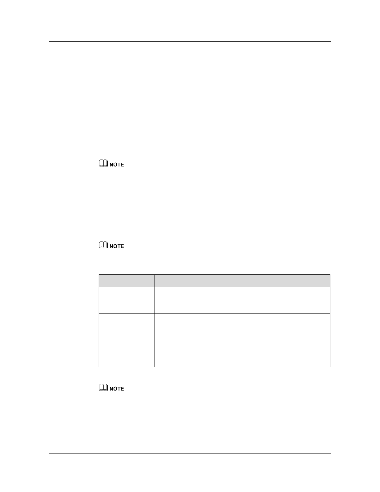
The home page is displayed, as shown in Figure 2-1.
Issue 01 (2014-12-23) Huawei
12
Copyright © Huawei Technologies Co., Ltd.
Page 21

HUAWEI TE40&TE50&TE60 Videoconferencing
Proprietary and Confidential
Endpoint
Administrator Guide 2 Web-based Login
Figure 2-1 Home page of the endpoint web interface
(1) Menu bar
(5) Desktop icons
(2) Expand/Collapse
button
(6) Area for
displaying logs
(3) Area for displaying your
site name
(7) Area for displaying
messages
(4) Shortcut
bar
(8) Status icons
----End
To ensure data security, after accessing the endpoint web interface, close the browser and delete browser
caches.
Issue 01 (2014-12-23) Huawei
13
Copyright © Huawei Technologies Co., Ltd.
Page 22

HUAWEI TE40&TE50&TE60 Videoconferencing
Proprietary and Confidential
Endpoint
Administrator Guide 3 Menu Structure of the Web Interface
3
Menu Structure of the Web Interface
Knowing the menu structure of the endpoint web interface helps you quickly find each
function item.
All function items on the web interface can be accessed from the menu bar on the home page.
Figure 3-1 shows the menu structure.
Issue 01 (2014-12-23) Huawei
14
Copyright © Huawei Technologies Co., Ltd.
Page 23

HUAWEI TE40&TE50&TE60 Videoconferencing
Proprietary and Confidential
Endpoint
Administrator Guide 3 Menu Structure of the Web Interface
Figure 3-1 Web interface menu structure
Only the TE60 supports 4E1 functions.
To quickly access a function item, you can also choose Help > Site Map and click the
hyperlink for the function item.
For details about the menu structure of the remote controlled UI, see B Menu Structure of the Remote
Controlled UI.
Issue 01 (2014-12-23) Huawei
Copyright © Huawei Technologies Co., Ltd.
15
Page 24

HUAWEI TE40&TE50&TE60 Videoconferencing
Proprietary and Confidential
Endpoint
Administrator Guide 4 Conference Experience
About This Chapter
You can initiate or join conferences in multiple ways on the endpoint web interface. During a
conference, you can control the conference or share presentations.
4.1 Initiating a Point-to-Point Conference
You can initiate a point-to-point conference in multiple ways on the endpoint web interface.
4.2 Initiating a Multipoint Conference
You can initiate a multipoint conference in multiple ways on the endpoint web interface.
During a multipoint conference, all the sites can hear and view each other.
4.3 Scheduling a Conference
On your endpoint, you can schedule a conference to hold at specific time.
4.4 Joining a Conference Using the Conference Access Number
When initiating a conference for which the participant sites are uncertain, you can set only the
number of anonymous sites. With this setting, a site can join the conference by dialing the
conference access number and then following the interactive voice response (IVR)
instructions.
4
Conference Experience
4.5 Joining an MSUC Convergent Conference
Huawei videoconferencing systems can be used in the Microsoft Unified Communications
(MSUC) environment. Register the endpoint (networked with MSUC) with a Lync Server
using SIP. After that, the endpoint can place calls to Lync clients, receive calls from Lync
clients, and view Lync clients' online status.
4.6 Joining an HD-Video Conference over an IMS Network
The endpoint can join an HD video conference over an IMS network.
4.7 Sharing a Presentation
A computer can be connected to the endpoint to share files, and the remote sites can view both
your video and the desktop contents of the computer.
4.8 Creating and Sending Captions
You can create and preview a banner or caption on your endpoint.
Issue 01 (2014-12-23) Huawei
16
Copyright © Huawei Technologies Co., Ltd.
Page 25

HUAWEI TE40&TE50&TE60 Videoconferencing
Proprietary and Confidential
or the call might even fail to be set
Endpoint
Administrator Guide 4 Conference Experience
4.9 Using the Do-Not-Disturb Function
If you do not want to be disturbed by incoming calls, you can enable the Do-not-disturb
function.
4.10 Controlling a Conference
After initiating a multipoint conference, you can control the video and audio of sites using
conference control functions.
4.11 Recording a Conference
Your endpoint can record local and multipoint conferences.
4.12 Sending and Receiving Instant Messages
During a conference, you can send instant messages to remote sites and view or close the
instant messages sent from remote sites.
4.1 Initiating a Point-to-Point Conference
You can initiate a point-to-point conference in multiple ways on the endpoint web interface.
4.1.1 Initiating a Conference from the Call Page
On the call page, you can select a site, configure the line type and rate for the site, and place a
call to the site to start a conference.
Step 1 Choose Conference > Call.
Step 2 Select a remote site you want to call using either of the following methods:
Click Call History and select the remote site.
Enter the name, number, or IP address of the remote site.
Step 3 Set the site parameters, listed in Table 4-1.
Table 4-1 Site parameters
Parameter Description Setting
Site name/IP
address/Nu
mber
Line type
Specifies the name, number, or IP
address of the site you want to call.
Specifies the type of the line used to
place the call.
To call a Microsoft Lync site, set this
parameter to Auto or SIP.
To call a Cisco TelePresence
site, you must set this
parameter to the name of the
Cisco TelePresence site.
By default, the last used line
type is displayed.
Rate
Issue 01 (2014-12-23) Huawei
Specifies the data transmission rate
required.
The data transmission rates supported by
your endpoint vary depending on the
type of site you want to call.
Copyright © Huawei Technologies Co., Ltd.
Select the highest available data
transmission rate.
NOTE
If this parameter is set incorrectly,
the video quality will be affected
17
Page 26

HUAWEI TE40&TE50&TE60 Videoconferencing
Proprietary and Confidential
Endpoint
Administrator Guide 4 Conference Experience
Parameter Description Setting
up.
Call mode Specifies the call type.
Video: Place video calls
Voice: Place audio-only calls
The default value is Video.
This parameter is available only when
Line type is set to Auto or SIP.
The default settings of advanced conference parameters can meet the requirements of most simple
conferences. Alternatively, you can click Advanced Settings and set advanced conference parameters.
For the description of each advanced conference parameter, see 7.5.3 Setting Advanced Conference
Parameters.
Step 4 Click Call.
----End
4.1.2 Initiating a Conference from the Address Book
You can select a site from the address book and place a call to the site to initiate a conference.
Procedure
Step 1 Choose Address Book > Address Book.
Step 2 Select one site you want to call from the local address book or the Lightweight Directory
Access Protocol (LDAP) address book.
Step 3 Click Call.
----End
To modify the settings of a site you want to call, click the site.
4.1.3 Holding a Call
If you receive a call or want to call another site in a point-to-point conference, you can
perform call hold operations.
Prerequisites
The Multipoint call mode parameter has been set to Multipoint converge on System
Settings > Conference > Normal on the endpoint web interface.
Procedure
Scenario 1: You are in a point-to-point conference with site B, and site C calls you. You can
perform any of the operations described in Table 4-2.
Issue 01 (2014-12-23) Huawei
18
Copyright © Huawei Technologies Co., Ltd.
Page 27

HUAWEI TE40&TE50&TE60 Videoconferencing
Proprietary and Confidential
Endpoint
Administrator Guide 4 Conference Experience
Table 4-2 Call hold operations
Click... To...
Reject
Reject the incoming call and continue the current point-to-point
conference.
Accept & Hold
Active
Accept & End
Active
Answer the incoming call and place the current point-to-point
conference on hold.
NOTE
After performing this operation, you can choose Conference > Hold Call
and click any of the following:
Resume: Resume the conference call placed on hold and place the
active call on hold.
On hold: Place the active call on hold.
Hang up: Disconnect a site.
Answer the incoming call and end the current point-to-point
conference.
Ignore Ignore the incoming call and close the call handling dialog box.
Scenario 2: You are in a point-to-point conference with site B and call site C. You can perform
any of the following operations described in Table 4-3 in the dialog box that is displayed.
Table 4-3 Call operations
Click... To...
Hold Active & Call Place the current point-to-point conference on hold and call site C.
NOTE
After performing this operation, you can choose Conference > Hold Call
and click any of the following:
Resume: Resume the conference call placed on hold and place the
active call on hold.
On hold: Place the active call on hold.
Hang up: Disconnect a site.
Cancel Cancel calling site C.
4.2 Initiating a Multipoint Conference
You can initiate a multipoint conference in multiple ways on the endpoint web interface.
During a multipoint conference, all the sites can hear and view each other.
4.2.1 Understanding the MCU and Built-in MCU
The endpoint needs to use the MCU or built-in MCU to initiate a multipoint conference. If the
endpoint uses the built-in MCU to initiate a conference, no external MCU is required.
Issue 01 (2014-12-23) Huawei
19
Copyright © Huawei Technologies Co., Ltd.
Page 28

HUAWEI TE40&TE50&TE60 Videoconferencing
Proprietary and Confidential
Endpoint
Administrator Guide 4 Conference Experience
MCU
As an indispensable component in a multipoint conference, the MCU is responsible for
multiple functions, such as site access, video exchange, audio mixing, data processing, and
signaling interaction.
Built-in MCU
An endpoint with the built-in MCU function can initiate a multipoint conference by
implementing functions such as site access, video exchange, audio mixing, data processing,
and signaling interaction. The endpoint can work independently, without involving the other
components on the videoconferencing network in conference scheduling. In this case, the
endpoint functions as a mini MCU.
On the endpoint web interface, choose Maintenance > System Information, and check whether the
endpoint has a built-in MCU.
To provide the built-in MCU function, the endpoint requires a specified license. Contact Huawei
post-sales engineers to purchase the license.
Conferences held with the built-in MCU function have the following features:
After a point-to-point call is set up, site-by-site calls can be made to hold a multipoint
conference.
BFCP or H.239 presentation dual-stream conferences are supported. A SIP site supports
BFCP dual-stream, an H.323 site supports H.239 dual-stream, and a hybrid conference
supports both BFCP and H.239 dual-stream.
Conferences can be locked from the built-in MCU. After a conference is locked, calls
from new sites are restricted.
Conferences can be attended by both H.323 and SIP sites and support H.323 site control.
If a conference is held with a built-in MCU, only Presentation is available.
Built-in MCU Capabilities of TE40/TE50
The built-in MCU supports the access from six HD video sites and three audio-only sites
simultaneously in a conference.
The six HD video sites include the local site that uses its built-in MCU, that is, the
built-in MCU site.
A maximum of six 720p30 full-adaptive sites are supported.
G.722 or G.711 full adaptation is supported.
Built-in MCU Capabilities of TE60
The built-in MCU supports the access from nine HD video sites and three audio-only sites
simultaneously in a conference.
The nine HD video sites include the local site that uses its built-in MCU, that is, the
built-in MCU site.
A maximum of nine 720p30 full-adaptive sites are supported.
G.722 or G.711 full adaptation is supported.
Issue 01 (2014-12-23) Huawei
Copyright © Huawei Technologies Co., Ltd.
20
Page 29
HUAWEI TE40&TE50&TE60 Videoconferencing
Proprietary and Confidential
Endpoint
Administrator Guide 4 Conference Experience
Initiating a Multipoint Conference on the endpoint with a Built-in MCU
Before initiating a multipoint conference, you must enable the built-in MCU function. To do
so, choose System Settings > Conference > Normal and set Multipoint call mode to AUTO
or Built-in MCU.
To initiate a multipoint conference using the built-in MCU, call the first site and then place
calls one at a time to several other sites. For details about other methods for initiating a
multipoint conference, see 4.2.2 Initiating a Conference from the Predefined Conference Page,
4.2.3 Initiating a Conference from the Conference History Page, and 4.2.4 Initiating a
Conference from the Address Book Page.
For example, to use the built-in MCU of endpoint A to initiate a conference that includes
endpoints A, B, C, and D, perform the following steps:
From endpoint A, call endpoints B, C, and D until all the calls are set up.
If the built-in MCU of an endpoint is used during a conference, Lock conference can be selected from
the Conference control screen on the endpoint whose built-in MCU is being used to prevent unwanted
additional sites joining the conference.
Conference Control
Three types of roles exist in a multipoint conference initiated using the built-in MCU:
Endpoint to which the built-in MCU belongs, chair site, and non-chair sites. A site can request
chair control rights only after chair control is enabled on the Endpoint to which the built-in
MCU belongs. The chair control is enabled by default.
Only H.323 sites support conference control functions.
Table 4-4 Conference control in a multipoint conference initiated using the built-in MCU
Role Conference Control
Endpoint to which
the built-in MCU
Enable chair control, Disable chair control, Lock conference, Set
Continuous Presence, and Recording
belongs
Chair site
Release Chair, End conference, Delete Site, Add site, Set
Continuous Presence, and Recording
NOTE
Only H.323 sites where the endpoints in V100R001C10 are used support the
Conference Video Layout and Start functions.
Non-chair site Request chair
The recording function is available only when the recording server address is configured on the
Endpoint to which the built-in MCU belongs.
Continuous Presence on the Endpoint to Which the Built-in MCU Belongs
The Endpoint to which the built-in MCU belongs adjusts the continuous presence layout
based on the number of sites in the conference, and can add the local video and presentation
Issue 01 (2014-12-23) Huawei
21
Copyright © Huawei Technologies Co., Ltd.
Page 30

HUAWEI TE40&TE50&TE60 Videoconferencing
Proprietary and Confidential
Endpoint
Administrator Guide 4 Conference Experience
to continuous presence. A maximum of 7 sites are supported in continuous presence on the
TE40/TE50, and a maximum of 10 sites are supported in continuous presence on the TE60.
The maximum number of sites in continuous presence includes the local video and presentation.
For details about how to add the local video and presentation to continuous presence, see the
description of Add presentation to continuous presence and Add local video to continuous
presence in 7.5.2 Setting General Conference Parameters. The two parameters are invalid to H.323
sites where the endpoints in V100R001C10 are used. For these sites, you can press on the
remote control to add the local video or presentation to continuous presence.
4.2.2 Initiating a Conference from the Predefined Conference
Page
On your endpoint, you can create a conference on the predefined conference page and initiate
it from this page.
Prerequisites
You can use SiteCall or the built-in MCU to initiate a multipoint conference.
Procedure
Step 1 Choose Conference > Start Conference and click the Predefined Conferences tab.
Step 2 Click Create Conference and perform either of the following:
Step 3 Click .
SiteCall: Before initiating a conference, define the participant sites and register your
endpoint with the GK server. Then disable the built-in MCU as follows: Choose System
Settings > Conference > Normal and set Multipoint call mode to Multipoint
converge or OFF.
Built-in MCU: Before initiating a conference, enable the built-in MCU as follows:
Choose System Settings > Conference > Normal and set Multipoint call mode to
Built-in MCU or AUTO. If it is defined on the Service Management Center (SMC) as
a manageable participant, its built-in MCU capabilities will be restricted by the SMC. In
this case, consult the SMC administrator about the maximum number of calls supported
by the endpoint.
To provide the built-in MCU function, the endpoint requires a specific license. Contact Huawei
post-sales engineers to purchase the license.
Click Address Book. On the displayed tab, select the desired sites.
Click LDAP Address Book. On the displayed tab, search for and select the desired sites.
The selected sites are added to the site list on the right.
Step 4 Set the conference parameters.
If you use the built-in MCU to initiate the conference, set Conference Name, Rate, and
Support recording only.
If you use SiteCall to initiate the conference, set all the parameters listed in the table.
Issue 01 (2014-12-23) Huawei
22
Copyright © Huawei Technologies Co., Ltd.
Page 31

HUAWEI TE40&TE50&TE60 Videoconferencing
Proprietary and Confidential
Endpoint
Administrator Guide 4 Conference Experience
Table 4-5 Conference parameters
Parameter Description Setting
Conference
Name
Rate
Continuous
presence
Other
parameters
Specifies the name of the conference. -
Specifies the data transmission rate for
the conference.
Specifies the maximum number of site
videos that can be viewed
simultaneously during the conference.
When continuous presence is broadcast,
the sites in the conference can view the
videos of multiple sites simultaneously.
If you select Disable, the conference
does not support continuous presence.
Specifies the mode for setting conference
parameters.
Auto-sensing: Your endpoint sets
conference parameters to be the same
as the parameter settings described in
7.5 Specifying Conference Settings.
User defined: You must manually set
Conference control password,
Anonymous H.323 sites,
Anonymous PSTN sites, H.235
conference, and Paying site.
To help ensure conference
quality, set this parameter to
1920 kbps or a larger value.
The default value is Disable.
The default value is
Auto-sensing.
Conference
control
password
Anonymous
H.323 sites
Anonymous
PSTN sites
Specifies the password to the conference.
This password is required for:
The site that wants to chair the
conference to obtain the chair control
rights.
Anonymous sites to join the
conference for authentication. For
details about how to use the password
to join an authentication conference,
see 4.4 Joining a Conference Using
the Conference Access Number.
Specify the number of IP or public
switched telephone network (PSTN)
anonymous sites that are allowed to join
the conference.
Anonymous sites are the sites whose
numbers are not defined. To allow five
IP or PSTN anonymous sites to join the
conference, set the Anonymous H.323
sites parameter to 5. To disallow any IP
or PSTN anonymous sites to join the
conference, set the Anonymous PSTN
Enter a value that contains 1 to
32 digits.
The default value is 0.
Issue 01 (2014-12-23) Huawei
23
Copyright © Huawei Technologies Co., Ltd.
Page 32

HUAWEI TE40&TE50&TE60 Videoconferencing
Proprietary and Confidential
Endpoint
Administrator Guide 4 Conference Experience
Parameter Description Setting
sites parameter to 0.
H.235
conference
Paying site
Support live
broadcast
Specifies the conference security type.
Insecure conference: No data
transmitted during the conference is
encrypted.
Secure media conference: Media
streams are encrypted.
Specifies the party that will be charged
for the conference.
Local site: The local site pays for the
conference.
Another site: Another site pays for
the conference. If you select this
option, you must fill in Paying
account and Paying password.
Specifies whether your endpoint supports
live broadcasting for multipoint
conferences hosted by standalone MCUs.
The default value is Insecure
conference.
To enhance the communication
security on your endpoint,
select Secure media
conference.
NOTE
If you select Secure media
conference, confirm that
Encryption is set to Enable or
Maximum interconnectivity on
your endpoint and the endpoints to
call. Otherwise, the calls will fail.
The default value is Local site.
By default, this parameter is
deselected, indicating that the
endpoint does not support live
broadcasting.
Support
recording
Specifies whether your endpoint supports
recording for multipoint conferences
hosted by standalone MCUs.
Date Specifies the conference start time.
This parameter is mandatory only when
you schedule a conference.
Duration Specifies the conference duration.
This parameter is mandatory only when
you schedule a conference.
Step 5 Click Hold Conference.
The conference is initiated according to the parameters you set.
----End
By default, this parameter is
deselected, indicating that the
endpoint does not support
recording.
No default value is set for this
parameter.
Unit: minute
Do not leave this parameter
blank.
Issue 01 (2014-12-23) Huawei
24
Copyright © Huawei Technologies Co., Ltd.
Page 33

HUAWEI TE40&TE50&TE60 Videoconferencing
Proprietary and Confidential
Endpoint
Administrator Guide 4 Conference Experience
4.2.3 Initiating a Conference from the Conference History Page
The conference history contains the records of conferences your endpoint initiated or attended
and sites your endpoint placed calls to or received calls from. You can select a record from the
conference history to initiate a new conference.
Prerequisites
You can use SiteCall or the built-in MCU to initiate a multipoint conference.
SiteCall: Your endpoint has registered with a GK server, and Multipoint call mode is set
to Multipoint converge or OFF under System Settings > Conference > Normal.
Built-in MCU: Multipoint call mode is set to Built-in MCU or AUTO under System
Settings > Conference > Normal.
To provide the built-in MCU function, the endpoint requires a specific license. Contact Huawei
post-sales engineers to purchase the license.
Background
The conference history stores a maximum of 50 records.
Procedure
Step 1 Choose Conference > Start Conference and click the Conference History tab.
Step 2 Select a record and click .
The conference starts.
----End
4.2.4 Initiating a Conference from the Address Book Page
From the address book on your endpoint, you can select sites to initiate a conference.
Prerequisites
You can use SiteCall or the built-in MCU to initiate a multipoint conference.
SiteCall: Your endpoint has registered with a GK server, and Multipoint call mode is set
to Multipoint converge or OFF under System Settings > Conference > Normal.
Built-in MCU: Multipoint call mode is set to Built-in MCU or AUTO under System
Settings > Conference > Normal.
To provide the built-in MCU function, the endpoint requires a specific license. Contact Huawei
post-sales engineers to purchase the license.
Procedure
Step 1 Choose Address Book > Address Book.
Issue 01 (2014-12-23) Huawei
25
Copyright © Huawei Technologies Co., Ltd.
Page 34

HUAWEI TE40&TE50&TE60 Videoconferencing
Proprietary and Confidential
Endpoint
Administrator Guide 4 Conference Experience
Step 2 Select sites from the local address book. Alternatively, search for sites from the LDAP
address book, save the found sites in the local address book, and select the sites from the local
address book. Then click Start Conference.
Step 3 Set the conference parameters. Refer to 4.2.2 Initiating a Conference from the Predefined
Conference Page.
Step 4 Click Hold Conference.
The conference starts.
----End
4.3 Scheduling a Conference
On your endpoint, you can schedule a conference to hold at specific time.
Prerequisites
You have set Conference line type in advanced conference settings to H.323 or Auto. For
details about the settings, see 7.5.3 Setting Advanced Conference Parameters.
Procedure
Step 1 Choose Conference > Start Conference and click the Schedule Conference tab.
Step 2 Click New Schedule. Select conference sites and set the conference parameters. Refer to 4.2.2
Step 3 Click Schedule.
Step 1 Choose Conference > Start Conference and click the Predefined Conferences tab.
Step 2 Click Create Conference or an entry in the Conference Name column.
Step 3 Select conference sites and set the conference parameters. Refer to 4.2.2 Initiating a
Your endpoint has registered with a GK server, and Multipoint call mode is set to
Multipoint converge or OFF under System Settings > Conference > Normal.
Method 1: Create and schedule a conference.
Initiating a Conference from the Predefined Conference Page.
The conference is scheduled.
----End
Method 2: Create and schedule a predefined conference or schedule a predefined conference
that exists in the Predefined Conferences list.
The Hold Conference page is displayed.
Conference from the Predefined Conference Page.
Step 4 Click Schedule.
The conference is scheduled.
----End
Issue 01 (2014-12-23) Huawei
26
Copyright © Huawei Technologies Co., Ltd.
Page 35

HUAWEI TE40&TE50&TE60 Videoconferencing
Proprietary and Confidential
Endpoint
Administrator Guide 4 Conference Experience
Method 3: Schedule a conference in the Conference History list.
Step 1 Choose Conference > Start Conference and click the Conference History tab.
Step 2 Click an entry in the Conference Name column.
The Hold Conference page is displayed.
Step 3 Select conference sites and set the conference parameters. Refer to 4.2.2 Initiating a
Conference from the Predefined Conference Page.
Step 4 Click Schedule.
The conference is scheduled.
----End
Conferences scheduled using any of the preceding methods are displayed in the Schedule
Conference list.
4.4 Joining a Conference Using the Conference Access
Number
Background
Procedure
Step 1 Obtain the access number for the authentication conference.
Step 2 Choose Conference > Call.
Step 3 In Site name/IP address/Number, enter the access number.
Step 4 Set the call parameters. Refer to 4.1.1 Initiating a Conference from the Call Page.
When initiating a conference for which the participant sites are uncertain, you can set only the
number of anonymous sites. With this setting, a site can join the conference by dialing the
conference access number and then following the interactive voice response (IVR)
instructions.
A site dials a conference access number and follows the IVR instructions to enter the specified
password to join a conference. This process is called two-stage dialing.
When a conference starts, endpoints that have joined the conference can view the conference
access number by choosing Maintenance > System Status > Conference. Anonymous sites
can obtain the conference access number and authentication password from the SMC
administrator or chair site using other methods.
Select the highest data transmission rate supported by your endpoint to increase the call success rate.
Step 5 Click Call.
Step 6 Choose Conference > Second Dial. Follow the IVR instructions to select a language and
enter the password (if any) to join a conference.
Issue 01 (2014-12-23) Huawei
27
Copyright © Huawei Technologies Co., Ltd.
Page 36

HUAWEI TE40&TE50&TE60 Videoconferencing
Proprietary and Confidential
Endpoint
Administrator Guide 4 Conference Experience
----End
4.5 Joining an MSUC Convergent Conference
Huawei videoconferencing systems can be used in the Microsoft Unified Communications
(MSUC) environment. Register the endpoint (networked with MSUC) with a Lync Server
using SIP. After that, the endpoint can place calls to Lync clients, receive calls from Lync
clients, and view Lync clients' online status.
Background
After the endpoint joins the MSUC network, the following can be implemented.
The endpoint and Lync clients can place calls to each other.
−
During a point-to-point call, switching between audio-only and video calls is
available on both the endpoint and Lync client.
−
The endpoint supports call forwarding on Lync clients. For example, if calls to Lync
A has been set to be forwarded to Lync B, then after a call between Lync A and
endpoint C is set up, endpoint C automatically disconnects from Lync A and calls
Lync B.
From Address Book you can view Lync clients' online status.
To view a Lync client's online status, you must save that Lync client to the local address
book.
Procedure
Step 1 Register the endpoint with the MSUC network.
The following describes how the endpoint places a call to the Lync client.
1. On the endpoint web interface, choose System Settings > Network and click the
H.323/SIP Settings tab.
2. Click the SIP tab and set the parameters for interworking with the MSUC to register the
endpoint with a Lync server. Table 4-6 describes the related parameters.
Table 4-6 SIP parameters
Parameter Description Setting
Register
with server
Specifies whether your endpoint registers
with a Lync Server.
Set this parameter to Enable.
An endpoint that registers with a Lync
Server can place calls to remote sites
using their IP addresses or site numbers
if the remote sites also register with Lync
Servers.
NOTE
If you select this parameter, you must also set
Server address, Site number, User name,
and Password.
Server Specifies the IP address or domain name
Issue 01 (2014-12-23) Huawei
Example 1: 192.168.1.10
28
Copyright © Huawei Technologies Co., Ltd.
Page 37

HUAWEI TE40&TE50&TE60 Videoconferencing
Proprietary and Confidential
Endpoint
Administrator Guide 4 Conference Experience
Parameter Description Setting
address of the Lync Server with which you want
Example 2: lync.zdtest.com
the endpoint to register.
If you set this parameter to the Lync
Server domain name, enable the domain
name server (DNS). If the DNS is not
enabled, enable Proxy server.
Conference
service
number
Enable
proxy server
Proxy server
address
Site number
Specifies the site number for your
endpoint.
If your endpoint registers with a Lync
Server, endpoints that also register with
the Lync Server can dial this site number
to call your endpoint.
User name
Password
Specifies the user name for
authentication registration.
Server type Specifies the SIP server type.
OCS: Select this option if your
endpoint registers with the Microsoft
Office Communications Server
(OCS) or Microsoft Lync Server.
CISCO VCS: Select this option if
your endpoint registers with the Cisco
TelePresence Video Communication
Server (VCS).
Standard: Select this option if your
endpoint registers with other SIP
servers.
You do not need to set this
parameter.
You do not need to set this
parameter.
You do not need to set this
parameter.
Example: 123@zdtest.com
Obtain this value from the Lync
Server administrator.
Example: lync_1@zdtest.com
Obtain the value of this
parameter from the Lync Server
administrator.
Set this parameter to OCS.
Transmissio
n type
Issue 01 (2014-12-23) Huawei
Specifies the protocol used for SIP
signaling transmission.
TCP: Use the Transmission Control
Protocol (TCP) to implement
transmission reliability.
UDP: Use the User Datagram
Protocol (UDP) to implement
transmission with reduced latency.
TLS: Use Transport Layer Security
(TLS) to implement transmission
Copyright © Huawei Technologies Co., Ltd.
Only TCP and TLS
transmission are supported.
29
Page 38

HUAWEI TE40&TE50&TE60 Videoconferencing
Proprietary and Confidential
Endpoint
Administrator Guide 4 Conference Experience
Parameter Description Setting
security. Note that selecting this
option may affect the call rate. If you
select this parameter, you can set SSL
version.
SSL version
Specifies the encryption protocol used
for SIP calls, including TLS 1.0 and SSL
3.0.
Video
request
handling
Specifies how your endpoint handles
video requests from a remote endpoint
during a point-to-point SIP audio call or
multipoint conference.
Accept automatically: Your
endpoint automatically accepts video
requests from the remote endpoint.
Reject automatically: Your endpoint
automatically rejects video requests
from the remote endpoint.
Manual: Your endpoint prompts you
to accept video requests from the
remote endpoint.
3. Click Save.
Step 2 Place a call from the endpoint to the Lync client.
1. Choose Conference > Call.
2. In the text box, enter the Lync client number.
3. Click Call.
The default value is TLS 1.0.
The default value is Manual.
----End
4.6 Joining an HD-Video Conference over an IMS
Network
The endpoint can join an HD video conference over an IMS network.
Background
Borne by the standard IP protocol, IMS uses VoIP applications based on the standard SIP
applications of the 3GPP to provide fixed and mobile multimedia services for operators.
Integrating MCUs can enhance the functionality of the Huawei IMS HD videoconferencing
solution.
Issue 01 (2014-12-23) Huawei
Copyright © Huawei Technologies Co., Ltd.
30
Page 39

HUAWEI TE40&TE50&TE60 Videoconferencing
Proprietary and Confidential
Endpoint
Administrator Guide 4 Conference Experience
Prerequisites
You have obtained the required authentication information from the IMS administrator:
unified access number, conference ID, and conference password.
Endpoint users can obtain the required authentication information allocated by the IMS through emails,
text messages, notices, or other methods.
Procedure
Step 1 Register the endpoint with the network where the IMS is located.
1. On the endpoint web interface, choose System Settings > Network and click the
H.323/SIP Settings tab.
2. Click the SIP tab and set the parameters for interworking with the IMS, as described in
Table 4-7.
Table 4-7 SIP parameters
Parameter Description Setting
Register
with server
Server
address
Specifies whether your endpoint registers
with an IMS server.
Only endpoints that have registered with
IMS servers can join the IMS network.
An endpoint that registers with an IMS
server can place calls to remote sites
using their IP addresses or site numbers
if the remote sites also register with IMS
servers.
NOTE
If you select this parameter, you must also set
Server address, Conference service
number, Site number, User name, and
Password.
Specifies the IP address or domain name
of the IMS server with which you want
the endpoint to register.
If you set this parameter to the IMS
server domain name, enable the domain
name server (DNS). If the DNS is not
enabled, enable Proxy server.
Set this parameter to Enable.
IP address example:
192.168.1.10
Domain name example:
huawei.com
It is recommended that you set
Server address to the domain
name of the IMS server with
which you want the endpoint to
register.
Conference
service
number
Proxy server
Issue 01 (2014-12-23) Huawei
Specifies the conference service number
for your endpoint to initiate conferences
over an IP multimedia subsystem (IMS)
network.
Specifies whether to enable the proxy
server.
You must enable the proxy server when
Copyright © Huawei Technologies Co., Ltd.
Set this parameter to the
conference service number
obtained from the IMS network
administrator.
Set this parameter to Enable.
31
Page 40

HUAWEI TE40&TE50&TE60 Videoconferencing
Proprietary and Confidential
request
video requests from a remote endpoint
Endpoint
Administrator Guide 4 Conference Experience
Parameter Description Setting
using the IMS network.
Proxy server
address
Specifies the address of the proxy server.
If you set Server address to the IMS
server domain name, set this parameter
to the IP address bound to that domain
name.
Site number
Specifies the site number for your
endpoint.
If your endpoint registers with an IMS
server, endpoints that also register with
the IMS server can dial this site number
to call your endpoint.
User name
Password
Specifies the user name for
authentication registration.
Server type Specifies the SIP server type.
OCS: Select this option if your
endpoint registers with the Microsoft
Office Communications Server
(OCS) or Microsoft Lync Server.
CISCO VCS: Select this option if
your endpoint registers with the Cisco
TelePresence Video Communication
Server (VCS).
Standard: Select this option if your
endpoint registers with other SIP
servers.
Example: 192.168.1.10.
The parameter value must
contain only digits.
Example: 12345
The value can contain digits,
letters, and special characters,
such as @ # %.
Example:
+0867552842007@huawei.co
m
Obtain the value of this
parameter from the IMS server
administrator.
Set this parameter to Standard.
Transmissio
n type
Video
Issue 01 (2014-12-23) Huawei
Specifies the protocol used for SIP
signaling transmission.
TCP: Use the Transmission Control
Protocol (TCP) to implement
transmission reliability.
UDP: Use the User Datagram
Protocol (UDP) to implement
transmission with reduced latency.
TLS: Use Transport Layer Security
(TLS) to implement transmission
security.
Specifies how your endpoint handles
Copyright © Huawei Technologies Co., Ltd.
Set this parameter to UDP.
The IMS network only supports
UDP transmission.
The default value is Manual.
32
Page 41

HUAWEI TE40&TE50&TE60 Videoconferencing
Proprietary and Confidential
Endpoint
Administrator Guide 4 Conference Experience
Parameter Description Setting
handling during a point-to-point SIP audio call or
multipoint conference.
Accept automatically: Your
endpoint automatically accepts video
requests from the remote endpoint.
Reject automatically: Your endpoint
automatically rejects video requests
from the remote endpoint.
Manual: Your endpoint prompts you
to accept video requests from the
remote endpoint.
3. Click Save.
Step 2 Choose Conference > Call.
Step 3 In the text box, enter the conference unified access number.
Step 4 Click Call.
Step 5 Choose Conference > Second Dial.
Enter the required authentication information, such as the conference ID and password, as
prompted.
----End
Result
After the IMS authenticates the password, the endpoint can join an HD video conference over
an IMS network.
4.7 Sharing a Presentation
A computer can be connected to the endpoint to share files, and the remote sites can view both
your video and the desktop contents of the computer.
Prerequisites
The presentation sharing function has been enabled, and the presentation parameters have
been set. By default, the endpoint has the presentation sharing function enabled, and the
default presentation parameter settings support presentation sharing. To modify these
parameters, see 7.5.3 Setting Advanced Conference Parameters.
The presentation video source has been connected.
Wired connection
Use a cable to connect the computer to a video input port on the endpoint.
Air content sharing client
1. (Optional) In the address box, enter the endpoint IP address and press Enter.
Issue 01 (2014-12-23) Huawei
33
Copyright © Huawei Technologies Co., Ltd.
Page 42

HUAWEI TE40&TE50&TE60 Videoconferencing
Proprietary and Confidential
Endpoint
Administrator Guide 4 Conference Experience
2. (Optional) In the upper left corner of the login page, click Download Air Content
Sharing Client and install the client as prompted.
The icon of the air content sharing client is displayed on the desktop when the
installation is complete.
If this is the first time you are installing the air content sharing client, you must restart
your computer before you can use it.
3. Double-click .
4. Double-click the endpoint to connect, or enter the endpoint IP address and click
Connect.
5. In the displayed dialog box, enter the password and click Connect.
The default password is Change_Me. For details, see 7.7.5 Setting the Air Content
Sharing Password.
Alternatively, ignore the dialog box and watch for the message An air content sharing source device
requests to connect to your endpoint. Accept? that will be displayed on the endpoint web interface
and remote controlled UI. When the message is displayed, select Accept. The client then successfully
connects to the endpoint without any passwords.
Background
Procedure
Step 1 Choose Conference > Presentation.
Step 2 In the displayed dialog box, click Share.
You can select either of the following modes for sharing a presentation:
Auto: The endpoint automatically sends the video along with the presentation. This
mode is available only when Presentation mode is set to Live.
Manual: You can use the remote control to share a presentation.
For details, see 7.5.3 Setting Advanced Conference Parameters.
However, in live mode, the endpoint does not support presentation sharing using SIP.
On a Microsoft unified communications (MSUC) network, the endpoint does not support
presentation sharing.
The presentation is shared with remote sites.
----End
To stop sharing the presentation, click Stop.
4.8 Creating and Sending Captions
You can create and preview a banner or caption on your endpoint.
Issue 01 (2014-12-23) Huawei
34
Copyright © Huawei Technologies Co., Ltd.
Page 43

HUAWEI TE40&TE50&TE60 Videoconferencing
Proprietary and Confidential
Endpoint
Administrator Guide 4 Conference Experience
Procedure
Step 1 Choose Conference > Caption.
Step 2 Click Middle Caption, Bottom Caption, or Banner. Then you can:
Share a caption in the Caption List list or a banner in the Banner Title list.
Preview a caption or banner on the display at your site.
Edit a caption or banner.
Save a caption or banner.
You can save a maximum of 10 entries to the Caption List or Banner Title list.
Create or delete a caption or banner.
----End
4.9 Using the Do-Not-Disturb Function
If you do not want to be disturbed by incoming calls, you can enable the Do-not-disturb
function.
Procedure
Step 1 Choose Conference > Do-not-disturb.
The Do-not-disturb dialog box is displayed.
Step 2 Select Enable for Do-not-disturb and click OK.
----End
4.10 Controlling a Conference
After initiating a multipoint conference, you can control the video and audio of sites using
conference control functions.
Icons on the Conference Control Page
Table 4-8 lists common icons displayed on the conference control page.
Table 4-8 Icons on the conference control page
Ico
Description
n
The site is not in the conference.
The site is in the conference.
Ico
Description
n
Your site is chairing the conference.
Issue 01 (2014-12-23) Huawei
The site is being broadcast.
The speakers of the site have been
muted, and the site cannot hear the
Copyright © Huawei Technologies Co., Ltd.
The site is being viewed.
The microphones of the site have
been muted, and the other sites in the
35
Page 44

HUAWEI TE40&TE50&TE60 Videoconferencing
Proprietary and Confidential
Endpoint
Administrator Guide 4 Conference Experience
Ico
n
Description
Ico
n
Description
current conference. conference cannot hear the site.
The site is sharing a presentation.
The site is a PSTN, H.323 PHONE,
or SIP audio site.
Table 4-9 lists the icons used to adjust the site display mode on the conference control page.
Table 4-9 Icons used to adjust the site display mode
Icon Description
Refreshes the conference control page.
Displays sites in a list.
Displays sites as icons.
Controlling a Multipoint Conference Hosted by the MCU
Note that not all the conference control functions listed in Table 4-10 are available on the
conference control page during a conference, depending on your role in the conference and
the settings of conference control page.
Table 4-10 lists the conference control functions available in a multipoint conference hosted
by the MCU.
Table 4-10 Conference control functions
Conferenc
e Control
Function
Request
Chair
Applica
ble
Role
Non-cha
ir site
Description
The conference chair site can use more conference control
functions than other sites.
Only non-chair sites can request chair control rights when no
chair site exists in a conference. Audio-only sites cannot request
chair control rights.
To request chair control rights, click Request Chair and enter
the conference control password, that is, the chair password.
NOTE
Obtain the conference control password from the SMC administrator or
the site that initiates the conference.
Issue 01 (2014-12-23) Huawei
36
Copyright © Huawei Technologies Co., Ltd.
Page 45

HUAWEI TE40&TE50&TE60 Videoconferencing
Proprietary and Confidential
Endpoint
Administrator Guide 4 Conference Experience
Conferenc
e Control
Function
Request
Floor
View Site
Applica
ble
Role
Non-cha
ir site
Non-cha
ir site
Chair
site
Description
If a non-chair site wants to speak during a conference, the site
can request the floor from the chair site. This function is
especially useful when a remote site is being broadcast.
This function is available only when a chair site exists in the
conference. After a site requests the floor, the request is
submitted to the chair site. The chair site can then determine
whether to give the floor to the site.
To give the floor to the requesting site, the chair site clicks
Sites Requesting Floor and clicks the site in the list. The site
is broadcast, and all the sites, except the chair site and the site
given the floor, are muted.
If the chair site does not give the floor to the requesting site,
the conference status remains unchanged.
Non-chair site: can use this function when no site or
continuous presence is being broadcast during a conference;
can view the sites residing on the local MCU or MCUs of the
same level only.
Chair site: can view any sites residing on the local MCU and
MCUs cascaded to the local MCU; can view a site even when
another site is being broadcast in continuous presence.
To view a single site, click View Site and select the site or
continuous presence to view.
To view sites in turn, click View Site, select In Turn on the
View Site page, select the sites to view one by one, and click
Start Viewing Sites in Turn. To stop viewing sites in turn, click
Stop Viewing Sites in Turn.
Revoke
Chair
Site that
initiates
the
conferen
ce
Call Site
Call All
Add Site
Chair
site
Chair
site
Issue 01 (2014-12-23) Huawei
Copyright © Huawei Technologies Co., Ltd.
Click Revoke Chair. When chair control rights are revoked, no
chair site exists in the conference. Sites in the conference can
then request to chair the conference.
You can place a call to a site that is not in the conference. The
site joins the conference after answering the call.
To call an absent site, click Call Site. To call all absent sites
included in the conference site list into the conference, click Call
All.
The status of a successfully connected site changes from to
.
You can add sites to an ongoing conference, regardless of
whether those sites have been defined in the address book. The
MCU hosting the conference then places calls to the added sites.
To add sites from the local or LDAP address book or add sites
that have not been defined in the address book, click Add Site.
37
Page 46

HUAWEI TE40&TE50&TE60 Videoconferencing
Proprietary and Confidential
Endpoint
Administrator Guide 4 Conference Experience
Conferenc
e Control
Function
Delete Site
Hang Up
Broadcast
Site
Applica
ble
Role
Chair
site
Chair
site
Chair
site
Description
To delete an absent site or a site that has joined the conference,
click Delete Site, select the site, and confirm the operation.
The chair site can disconnect a site from the conference and
remove the site from the site list. To enable the site to join the
conference again, the chair site must add the site to the
conference by performing the Add Site operation.
To disconnect a site that has joined the conference, click Hang
Up, select the site, and confirm the operation. After a site is
disconnected, the site still belongs to the conference but is
marked with . To have the site join the conference again, the
chair site can perform the Call Site operation.
The chair site can broadcast any non-audio-only site, including
the chair site itself, or broadcast multiple sites in turn.
To broadcast a single site, click Broadcast Site and select the
site to broadcast. When a site is broadcast, all non-chair sites are
forced to view the video of the broadcast site while the chair site
can view the video of any site that is present at the conference.
To stop broadcasting a site, perform Stop Broadcasting or
Discussion operation.
To broadcast sites in turn, click In Turn, select In Turn on the
Broadcast Site page, select the sites to broadcast one by one, and
click Start Broadcasting Sites in Turn. When multiple sites are
broadcast in turn, all sites are forced to view the video of the
broadcast sites. To stop broadcasting sites in turn, click Stop
Broadcasting Sites in Turn.
End
Conference
Set
Continuous
Chair
site
Chair
site
Presence
Mute/Unm
ute Speaker
Issue 01 (2014-12-23) Huawei
Chair
site
Copyright © Huawei Technologies Co., Ltd.
If a conference is completed before the scheduled time, the chair
site can use the End Conference function to end the conference
in advance.
View multiple sites at the same time.
The continuous presence function is used to display the video
from two or more sites on the same display at the same time. The
number of the sites to be displayed and the layout of the site
videos vary according to continuous presence modes.
This function is available only when continuous presence
resources have been reserved for the conference.
Click Set Continuous Presence, and choose a layout mode from
the Layout drop-down list box on the Set Continuous Presence
page. You can click a site to display the site in the highlighted
pane as required.
To disable the speaker of a site, click Mute Speaker and
select the site. The site is marked with and cannot hear
other sites in the conference.
To enable the speaker of a site, click Unmute Speaker and
select the site. Then the site can hear other sites in the
38
Page 47

HUAWEI TE40&TE50&TE60 Videoconferencing
Proprietary and Confidential
suf
ficient to cover an extension. To increase the chances of
Endpoint
Administrator Guide 4 Conference Experience
Conferenc
e Control
Function
Mute/Unm
ute MIC
Voice
activation
Applica
ble
Role
Chair
site
Chair
site
Description
conference.
To disable the microphone of a site, click Mute Microphone
and select the site. The site is marked with and cannot be
heard by other sites in the conference.
To enable the microphone of a site, click Unmute
Microphone and select the site. Then the site can be heard by
other sites in the conference.
Voice activation is used in discussion mode. When voice
activation is enabled, the site with the loudest voice is displayed
to other sites in the conference.
To enable voice activation, click Voice activation, set
Sensitivity on the Voice activation page based on your
experience, and click Start.
High: Voice activation threshold volume is low.
Medium: Voice activation threshold volume is set to a
medium level.
Low: Voice activation is performed when the voice volume is
high.
After you enable voice activation and set the sensitivity:
If the sound of one or multiple sites exceeds the voice
activation threshold defined on the MCU, the video of the
loudest site is broadcast.
If the voice activation threshold is not exceeded, the
conference status is not changed.
To disable the voice activation function, click Disable.
Lock
Presentatio
Chair
site
n
Extend
Conference
Issue 01 (2014-12-23) Huawei
Chair
site
Copyright © Huawei Technologies Co., Ltd.
Restrict the presentation sharing rights of a site or a conference.
Locking site presentation: When the chair site locks the
presentation rights of a site, only that site can share
presentations.
Locking conference presentation: When the chair site locks
the conference presentation, a site can share its presentation if
no other site in the conference is doing so.
To cancel locking, click Unlock Presentation.
NOTE
Before using this function, ensure that the MCU and service software
used with your endpoint support this function.
If a conference is not likely to be complete by the scheduled time,
click Extend Conference, set Extension time (in min.) on the
Extend Conference page, and click OK to extend the conference
for the specified time.
Before extending a conference, you must ensure that the
videoconferencing resources and your account balance are
39
Page 48

HUAWEI TE40&TE50&TE60 Videoconferencing
Proprietary and Confidential
Endpoint
Administrator Guide 4 Conference Experience
Conferenc
e Control
Function
Revoke
Presentatio
n
Discussion
Applica
ble
Role
Chair
site
Chair
site
Description
success, extend the conference by 30 minutes at most at a time.
To stop a site from sharing a presentation, the chair site can
revoke the presentation sharing right of the site.
This function is available in a dual-stream conference.
The chair site can enable discussion to cancel certain ongoing site
control or conference control operations, such as broadcasting
sites.
This Discussion function is used to cancel the following
operations performed by the chair site:
Broadcasting a site
Muting the speaker
Muting the microphone
Giving the floor
In discussion mode:
Audio: All sites have unmuted microphones, and the sound of
all the sites together are broadcast to every site.
Video: The video viewed by each site does not change and
each site can view any other site.
Give Floor
Sites
Requesting
Floor
Release
Chair
Monitor
Video
Chair
site
Chair
site
Chair
site
All sites
Using this function, the chair site can give the floor to a site and
mute all other sites.
After the chair site gives the floor to a site, the video and sound
of the site are broadcast, and all sites are muted, except the chair
site and the site that has the floor.
Although the Stop Broadcasting function is available even when
a site has the floor, the chair site cannot take back the floor using
Stop Broadcasting. After the chair site gives the floor to a site,
the video and sound of the site are broadcast, and all sites are
muted, except the chair site and the site that has the floor. If the
chair site clicks Stop Broadcasting at this time, broadcasting a
site stops, but the other non-chair sites are still muted.
During a conference, after a non-chair requests the floor, the site
is added to the floor-requesting sites list. The chair site can select
a site from the list to give the floor to that site. The video of that
site is then broadcast, and the microphones of all sites are muted,
except the chair site and the site that has the floor.
Once given the floor, the site is removed from the
floor-requesting sites list.
Releases chair control rights. When chair control rights are
released, any sites in the conference can request to become the
chair site.
View the video and presentation of a remote site in real time.
You can also adjust the sizes of the video and presentation. In
this way, you can monitor the status and video quality of the
Issue 01 (2014-12-23) Huawei
40
Copyright © Huawei Technologies Co., Ltd.
Page 49

HUAWEI TE40&TE50&TE60 Videoconferencing
Proprietary and Confidential
Endpoint
Administrator Guide 4 Conference Experience
Conferenc
e Control
Function
Applica
ble
Role
Description
remote site.
You can also monitor the video from the page described in
section 5.1 Viewing the Video.
NOTE
The video and presentation can be viewed in real time only when the
video monitoring function is enabled. This function involves personal
privacy. Ensure that its use complies with local laws and regulations.
Recording
Chair
site
From the conference control page, click Start to start recording
and Stop to stop recording.
NOTE
To ensure rights of sites, read the instructions and suggestions for using
recording products in the latest HUAWEI RSE6500 Security Maintenance
before using the products.
Controlling a Multipoint Conference Hosted by a Built-in MCU
Table 4-11 lists the conference control functions available in a multipoint conference hosted
by a built-in MCU.
Table 4-11 Conference control functions
Conferenc
e Control
Applicabl
e Role
Description
Function
Request
Chair
Enable
Chair
Control
Non-chair
site
endpoint to
which the
built-in
MCU
belongs
For details, see Table 4-10.
NOTE
Obtain the conference control password from the endpoint to which the
built-in MCU belongs.
The sites in the conference can request chair control rights
only after you enable the chair control on the endpoint. After a
site becomes the chair site, the following conference control
functions are unavailable to the endpoint:
Lock conference
Conference video layout
Recording
You can use the preceding conference control functions on the
endpoint only after click Disable Chair Control.
Disable
Chair
Control
endpoint to
which the
built-in
MCU
belongs
This function is used to disable chair control in a conference.
For example, if a chair site exists in a conference, the site
whose built-in MCU is being used can use this function to
revoke chair control rights. In addition, the sites in the
conference cannot request to become the chair site afterward.
Lock endpoint to The Lock conference operation can be performed only from
Issue 01 (2014-12-23) Huawei
41
Copyright © Huawei Technologies Co., Ltd.
Page 50

HUAWEI TE40&TE50&TE60 Videoconferencing
Proprietary and Confidential
Endpoint
Administrator Guide 4 Conference Experience
Conferenc
e Control
Applicabl
e Role
Function
conference which the
built-in
MCU
belongs
(when no
chair site
exists in
the
conference
)
Conference
Video
Layout
endpoint to
which the
built-in
MCU
belongs
(when no
chair site
exists in
the
conference
)
Chair site
Description
the endpoint whose built-in MCU is being used. After the
Lock conference operation is performed, the endpoint whose
built-in MCU is being used can call the other endpoints to join
the conference, but other endpoints cannot call into the
conference. To enable other endpoints to call into the
conference, perform the Unlock Conference operation.
This function is used to set the view displayed to all sites.
Voice activated, full screen: The remote sites view, in full
screen, the video of the site that generates the loudest
volume.
Voice activated, in panes: The remote sites view
continuous presence, with the main pane displaying the
video of the site that generates the loudest volume.
Bisect: The remote sites view, in bisect mode, the videos of
the other sites. The site that generates the louder volume is
highlighted. A presentation will not be displayed in this
layout.
Fixed site, full screen: The remote sites view, in full
screen, the video of a specified site. To view a site in full
screen, click it in the site list.
Fixed sites, in panes: The remote sites view continuous
presence, with the main pane displaying the video of a
specified site. To add a site to the main pane, click it in the
site list.
NOTE
After you set this parameter, the viewed site views other sites in
full screen or continuous presence mode.
This function is available only for H.323 sites where the endpoints
in V100R001C10 are used.
This function cannot be performed by the following sites at the
same time:
Chair site
Site where the built-in MCU is used (in a conference
hosted by a built-in MCU and not chaired by any site)
Recording
Issue 01 (2014-12-23) Huawei
endpoint to
which the
built-in
MCU
belongs
(when no
For details, see Table 4-10.
NOTE
This function is available only for H.323 sites where the endpoints in
V100R001C10 are used. To ensure rights of sites, read the instructions
and suggestions for using recoridng products in the latest HUAWEI
RSE6500 Security Maintenance before using the products.
chair site
exists in
the
Copyright © Huawei Technologies Co., Ltd.
42
Page 51

HUAWEI TE40&TE50&TE60 Videoconferencing
Proprietary and Confidential
Endpoint
Administrator Guide 4 Conference Experience
Conferenc
e Control
Applicabl
e Role
Description
Function
conference
)
Chair site
End
Conference
endpoint to
which the
For details, see Table 4-10.
built-in
MCU
belongs
Chair site
Release
Chair site For details, see Table 4-10.
Chair
Delete Site
Add Site
On the conference control page, you can also perform the following operations:
If the sites in a conference have been classified into groups in a site template, you can select a
group from the drop-down list box. Then, the sites in the
selected group are displayed in the preset mode. For details about how to set site groups, see
6.4 Customizing a Site Template.
4.11 Recording a Conference
Your endpoint can record local and multipoint conferences.
Prerequisites
To ensure rights of participants, read the instructions and suggestions for using recoridng
products in the latest HUAWEI RSE6500 Security Maintenance before using the products.
Table 4-12 Recording prerequisites
Conference Type Recording Prerequisites
Local conference
Multipoint conference hosted by a
Huawei standalone MCU (such as the
HUAWEI VP9660 MCU)
The recording server IP address or URL is set
on the endpoint.
The recording server is online.
NOTE
Check the recording server's online status from the
Service Management Center (SMC).
The endpoint and the recording server have
registered with a GK server.
Support recording is selected. For details,
Issue 01 (2014-12-23) Huawei
43
Copyright © Huawei Technologies Co., Ltd.
Page 52

HUAWEI TE40&TE50&TE60 Videoconferencing
Proprietary and Confidential
Endpoint
Administrator Guide 4 Conference Experience
Conference Type Recording Prerequisites
see 4.2.2 Initiating a Conference from the
Predefined Conference Page.
Background
Procedure
Step 1 Choose Conference > Control Recording.
Step 2 Click Start.
Multipoint conference hosted by a
built-in MCU
The recording server IP address or URL is set
on the endpoint.
During recording of local conferences, the endpoint cannot place or answer calls.
During recording of local conferences, you can perform Start, Pause, Resume, and Stop
operations. During recording of multipoint conferences, you can perform Start and Stop
operations.
When a Huawei standalone MCU is used to host a conference, you can enable or disable
live broadcast and recording for the conference.
When a built-in MCU is used to host a conference, you can enable or disable recording
for the conference.
During a multipoint conference, the chair site and the site where the built-in MCU is
used can perform recording operations.
To record a local conference, follow the following steps in this section. To record a
multipoint conference, see 4.10 Controlling a Conference.
The recording starts.
----End
To stop recording, click Stop.
4.12 Sending and Receiving Instant Messages
During a conference, you can send instant messages to remote sites and view or close the
instant messages sent from remote sites.
Prerequisites
Your endpoint is in a conference.
Your endpoint uses H.323. Only H.323 sites can send and receive instant messages.
T.140 captions have been enabled on your endpoint, because instant messages are a type
of T.140 caption. To enable T.140 captions, choose System Settings > Display >
Caption and set Sharing mode to T.140.
Issue 01 (2014-12-23) Huawei
44
Copyright © Huawei Technologies Co., Ltd.
Page 53

HUAWEI TE40&TE50&TE60 Videoconferencing
Proprietary and Confidential
Endpoint
Administrator Guide 4 Conference Experience
Procedure
Step 1 Choose Conference > Instant Message.
Step 2 In the displayed Instant Message dialog box, enter a message.
Step 3 Select the desired remote sites and click Send.
The message is sent to the remote sites. When receiving the message, the remote sites can
view and close the message.
----End
Issue 01 (2014-12-23) Huawei
45
Copyright © Huawei Technologies Co., Ltd.
Page 54

HUAWEI TE40&TE50&TE60 Videoconferencing
Proprietary and Confidential
Endpoint
Administrator Guide 5 Device Control
About This Chapter
After a conference starts, you can control the video and audio devices on the endpoint web
interface to obtain the expected conference effect.
5.1 Viewing the Video
After the video monitoring function is enabled, you can view the video and presentation of
local and remote sites on the endpoint web interface.
5.2 Controlling a Camera
You can perform pan, tilt, and zoom (PTZ) control over a local or remote camera.
5.3 Setting a Camera Preset
Camera presets are camera positions you set and save ahead of time. A camera preset stores
the pan, tilt, and zoom settings of the camera. You can easily control the camera by switching
between camera presets. You can configure remote camera presets before and during
conferences.
5.4 Selecting Video Sources
The endpoint provides multiple video input ports for connecting to video devices. When
multiple video devices are connected, you can set one video device as the local video source
and another one as the local presentation source. You can also select the video or presentation
to be displayed through video output ports.
5
Device Control
5.5 Controlling Audio
On your endpoint, you can adjust the audio effects. For example, you can adjust the volume of
the microphone and speaker.
5.6 Setting the Combined Picture
With the combined picture function, you can view multiple videos (such as the local and
remote videos and presentations) in Picture in Picture (PiP) or split-screen mode on one
display.
5.7 Setting Camera Parameters
On your endpoint, you can set the camera parameters, including video mode, noise reduction,
and video resolution. You can view the video result of your settings on the display connected
to your endpoint.
Issue 01 (2014-12-23) Huawei
46
Copyright © Huawei Technologies Co., Ltd.
Page 55

HUAWEI TE40&TE50&TE60 Videoconferencing
Proprietary and Confidential
Endpoint
Administrator Guide 5 Device Control
5.8 Setting Preferred Video Parameters
If you find that the displayed video deviates from its normal position, adjust the picture offset.
If a blurring or slight jitter issue occurs in the video, adjust the sampling phase.
5.9 Setting Up a PPPoE Dial-Up Connection
Correct IP parameter settings on your endpoint enable you to set up a PPPoE dial-up
connection with a broadband network to communicate with other network devices.
5.10 Using the Remote Control
You can use a virtual remote control on the web interface to control your endpoint.
5.1 Viewing the Video
After the video monitoring function is enabled, you can view the video and presentation of
local and remote sites on the endpoint web interface.
Prerequisites
Procedure
The video monitoring function has been enabled. This function can be enabled only on the
remote controlled UI. To enable the video monitoring function, choose Advanced >
Settings > Secured > Web Login and select Monitor video.
This function involves personal privacy. Ensure that its use complies with local laws and
regulations.
Log in to the web interface, choose Device Control > Device Control, and click the Video
Control tab to view the video of local and remote sites, as shown in Figure 5-1.
Issue 01 (2014-12-23) Huawei
47
Copyright © Huawei Technologies Co., Ltd.
Page 56

HUAWEI TE40&TE50&TE60 Videoconferencing
Proprietary and Confidential
Endpoint
Administrator Guide 5 Device Control
Figure 5-1 Viewing the video
You can click the drop-down list box to select the video source to view, or click Capture to
capture a picture of the video that is being played.
5.2 Controlling a Camera
You can perform pan, tilt, and zoom (PTZ) control over a local or remote camera.
Prerequisites
You are familiar with the following buttons for camera control:
: Turns the camera upward, downward, leftward, and rightward.
: Turns the camera forward.
: Enlarges the image taken by a camera.
: Zooms in on a scene.
: Shrinks the image taken by a camera.
: Zooms out on a scene.
: Automatically adjusts the camera focus.
Procedure
Step 1 Choose Device Control > Device Control.
Issue 01 (2014-12-23) Huawei
48
Copyright © Huawei Technologies Co., Ltd.
Page 57

HUAWEI TE40&TE50&TE60 Videoconferencing
Proprietary and Confidential
Endpoint
Administrator Guide 5 Device Control
Step 2 In the upper right corner of the Video Control page, select the camera you want to control, as
shown in Figure 5-2.
Figure 5-2 Camera control
When your endpoint is not in a conference, you can select only Local camera.
When your endpoint is in a conference, you can select Local camera or Remote camera.
By default, Local camera is selected.
When Monitor video is enabled, the video delivered from the camera under control is displayed in the
upper left corner of the Video Control page. You can then view the camera output while you control the
camera.
Step 3 Click the controls shown in Figure 5-2 to control cameras.
----End
When the desired video is displayed on the monitor, you can save the camera settings as a
preset so you can easily switch to the preset in the future. For details about how to set a
camera preset, see 5.3 Setting a Camera Preset.
5.3 Setting a Camera Preset
Camera presets are camera positions you set and save ahead of time. A camera preset stores
the pan, tilt, and zoom settings of the camera. You can easily control the camera by switching
between camera presets. You can configure remote camera presets before and during
conferences.
Prerequisites
You are familiar with how to control a camera. For details, see 5.2 Controlling a Camera.
Issue 01 (2014-12-23) Huawei
49
Copyright © Huawei Technologies Co., Ltd.
Page 58

HUAWEI TE40&TE50&TE60 Videoconferencing
Proprietary and Confidential
Endpoint
Administrator Guide 5 Device Control
Background
Table 5-1 lists the camera preset details.
Table 5-1 Camera preset details
Endpoint
Local 30 No
Remote Dynamically adjustable Yes
Saving a Camera Preset
Step 1 Choose Device Control > Device Control and click the Video Control tab.
On the displayed Video Control page, the camera control area is on the right side.
Step 2 Adjust the camera pan, tilt, and zoom settings until the desired video is displayed on the
monitor. Refer to 5.2 Controlling a Camera.
Step 3 Click the Save Preset tab, as shown in Figure 5-3.
Figure 5-3 Setting a Camera Presets
Number of Camera
Presets
Data Is Lost After Restart
Step 4 Select a number and click Confirm.
number and confirm the selection, the number is used for the current preset.
and confirm the selection, the current preset will overwrite the original preset.
Issue 01 (2014-12-23) Huawei
: indicates that the number has not been set for a preset. After you select this
: indicates that the number has been set for a preset. After you select this number
50
Copyright © Huawei Technologies Co., Ltd.
Page 59

HUAWEI TE40&TE50&TE60 Videoconferencing
Proprietary and Confidential
Endpoint
Administrator Guide 5 Device Control
----End
Switching Between Camera Presets
Step 1 On the Video Control page, click Switch Preset.
Step 2 Under Switch Preset, select a number corresponding to a preset, and click Confirm.
----End
Removing a Camera Preset
Step 1 On the Video Control page, click Save Preset tab.
Step 2 Under Save Preset, select the number corresponding to the preset you want to remove, and
click Clear.
----End
5.4 Selecting Video Sources
Prerequisites
Background
The endpoint provides multiple video input ports for connecting to video devices. When
multiple video devices are connected, you can set one video device as the local video source
and another one as the local presentation source. You can also select the video or presentation
to be displayed through video output ports.
To set the computer desktop as a video input source, ensure that you have set the computer
video to a video resolution and refresh rate that your endpoint supports. For details, see 7.3.5
Configuring Video Output.
Selecting video input sources
A video device can be a document camera, computer, record and playback device, or
DVD player. If you have connected multiple video devices to the input ports on your
endpoint, select local video and presentation sources from these connected devices.
The endpoint adopts difference policies to deliver the video and presentation based on
on-site situations:
−
In single-screen display mode, if no presentation is shared during a conference,
remote sites view the conference video of the local site; if a presentation is shared,
both the local and remote sites view the presentation.
−
In dual-screen mode, the display device connected to the main output port delivers
the video while the display device connected to the auxiliary output port delivers the
presentation.
−
During the layout switch in combined picture or continuous presence mode, remote
sites can always view the conference video of the local site.
For details about how to set video input ports, see 7.3.2 Configuring Video Input.
Selecting video output sources
Issue 01 (2014-12-23) Huawei
51
Copyright © Huawei Technologies Co., Ltd.
Page 60

HUAWEI TE40&TE50&TE60 Videoconferencing
Proprietary and Confidential
Endpoint
Administrator Guide 5 Device Control
During a conference, you can manually switch between the local video, local
presentation, remote video, and remote presentation to be displayed through a video
output port.
For details about how to set video output ports, see 7.3.5 Configuring Video Output.
Selecting the Video Source and Presentation Source
Step 1 Choose Device Control > Device Control and click the Video Control tab.
Step 2 In the lower left corner of the Video Control page, click the Video Input Source tab.
Step 3 Set Video Source and Presentation Source.
You can set the local video source to multi-view mode. For details about multi-view mode
settings, see 7.3.3 Setting the Multi-View Mode.
----End
Selecting the Video Output Source
Step 1 Choose Device Control > Device Control and click the Video Control tab.
Step 2 In the lower right corner of the Video Control page, click the Video Output Source tab.
Step 3 Select the video or presentation to be displayed through video output ports.
----End
5.5 Controlling Audio
On your endpoint, you can adjust the audio effects. For example, you can adjust the volume of
the microphone and speaker.
Procedure
Step 1 Choose Device Control > Device Control and click the Audio Control tab.
Step 2 Set the audio control parameters listed in Table 5-2.
Table 5-2 Audio control parameters
Parameter Description Setting
Audio Input
Audio Input Turns on or off all audio input sources. The default value is Unmute.
MIC 1
MIC 2 (only
TE60)
Adjusts the microphone volume at your
site. When you adjust this microphone
volume, the volume heard at remote sites
is adjusted accordingly.
The default value is +0dB.
Value range: -12 dB to +12 dB
RCA L
RCA R
Issue 01 (2014-12-23) Huawei
Adjusts the input volume of the RCA
port at your site. When you adjust this
input volume, the volume heard at
Copyright © Huawei Technologies Co., Ltd.
The default value is +0dB.
Value range: -12 dB to +12 dB
52
Page 61

HUAWEI TE40&TE50&TE60 Videoconferencing
Proprietary and Confidential
Endpoint
Administrator Guide 5 Device Control
Parameter Description Setting
remote sites is adjusted accordingly.
HDMI L
HDMI R
DP L (only
TE60)
DP R (only
TE60)
LINE IN L
(only TE50)
LINE IN R
(only TE50)
Microphone
array 1
MIC array 1
battery level
Microphone
array 2
MIC array 2
battery level
Microphone
array 3(only
TE60)
MIC array 3
battery
level(only
TE60)
Adjusts the input volume of the HDML
port at your site. When you adjust this
input volume, the volume heard at
remote sites is adjusted accordingly.
NOTE
This parameter is available only when the
HDMI port of the endpoint is connected to an
input source.
Adjusts the input volume of the DP port
at your site. When you adjust this input
volume, the volume heard at remote sites
is adjusted accordingly.
NOTE
This parameter is available only when the DP
port of the endpoint is connected to an input
source.
Adjusts the input volume of the LINE IN
port at your site. When you adjust this
input volume, the volume heard at
remote sites is adjusted accordingly.
Displays the microphone array volumes
and battery levels in real time.
The default value is +0dB.
Value range: -12 dB to +12 dB
The default value is +0dB.
Value range: -12 dB to +12 dB
The default value is +0dB.
Value range: -12 dB to +12 dB
-
Audio Output
Speaker
Volume
Alert tone Increases or decreases the alert tone
Issue 01 (2014-12-23) Huawei
Mutes or unmutes the speaker at your
site. To hear other sites, unmute the
speaker.
Adjusts the output volume heard at your
site. If both left and right audio channels
are available, the volume of both
channels is adjusted at the same time.
Copyright © Huawei Technologies Co., Ltd.
The default value is Unmute.
The default value is 15.
Value range: 0-21
The default value is 3.
53
Page 62

HUAWEI TE40&TE50&TE60 Videoconferencing
Proprietary and Confidential
Endpoint
Administrator Guide 5 Device Control
Parameter Description Setting
volume volume. Value range: 0-3
Sound Effect
Locally
output sound
from
AUDIO IN
AUDIOIN
remote
output
SPDIF
AUDIO IN
echo
cancellation
Music Mode
Bass
Middle
Treble
Specifies whether to allow the audio
input from the LINE IN port, the HDMI
port, or the RCA port to be heard at your
site.
Specifies whether to allow the audio
input from the LINE IN port, the HDMI
port, or the RCA port to be heard at
remote sites.
Specifies whether you can hear the sound
from the local SPDIF digital audio port
at your site. To hear the sound, set this
parameter to Unmute.
If echo cancellation is enabled, the
endpoint removes echo in the audio input
from the MIC 1 and MIC 2 (only TE60)
interfaces.
Specifies whether to enable the MIC 1
and MIC 2 (only TE60) to pick up the
music that is playing at the local site to
provide a better listening experience.
Adjusts the gain of bass, middle, and
treble tones.
The default value is Mute.
The default value is Unmute.
The default value is Mute.
The default value is Mute.
The default value is Mute.
The default value is +0dB.
Value range: -6 dB to +6 dB
PSTN
PSTN
Adjusts the volume of a PSTN call at
your site. When you adjust this volume,
the volume heard at remote sites is
adjusted accordingly.
Mix PSTN
audio
Specifies whether all sites (including
PSTN sites such as mobile phones) in a
conference can hear each other.
----End
Issue 01 (2014-12-23) Huawei
Copyright © Huawei Technologies Co., Ltd.
The default value is +0dB.
Value range: -12 dB to +12 dB
The default value is Enable. If
you retain the default value, all
sites in a conference can hear
each other.
Retain the default value when
your endpoint joins a
multipoint conference as a
PSTN site.
54
Page 63

HUAWEI TE40&TE50&TE60 Videoconferencing
Proprietary and Confidential
Endpoint
Administrator Guide 5 Device Control
5.6 Setting the Combined Picture
With the combined picture function, you can view multiple videos (such as the local and
remote videos and presentations) in Picture in Picture (PiP) or split-screen mode on one
display.
Prerequisites
Two or more of the following video sources are available: local video, local presentation,
remote video, and remote presentation.
Background
You can view multiple videos on one display at the same time. The positions, sizes, and
combination of these images are configurable.
Procedure
Step 1 Choose Device Control > Device Control and click the Combined Picture tab.
Step 2 Click Switch Video.
Videos are displayed in the mode you select.
----End
5.7 Setting Camera Parameters
On your endpoint, you can set the camera parameters, including video mode, noise reduction,
and video resolution. You can view the video result of your settings on the display connected
to your endpoint.
Procedure
Step 1 Choose Device Control > Device Control and click the Camera parameters adjustment
tab.
Step 2 Set the camera parameters listed in Table 5-3.
Table 5-3 Camera parameters
Parameter Description Setting
Camera
input
interface
Specifies the endpoint's video input port
to which the camera is to be connected.
The default value is 1 MAIN
IN.
Exposure
mode
Issue 01 (2014-12-23) Huawei
Specifies the mode for using natural
light. You can select either of the
following modes:
Auto: The camera automatically
selects the optimum configuration
based on the surrounding
Copyright © Huawei Technologies Co., Ltd.
The default value is Auto.
55
Page 64

HUAWEI TE40&TE50&TE60 Videoconferencing
Proprietary and Confidential
Endpoint
Administrator Guide 5 Device Control
Parameter Description Setting
environment.
Manual: You need to manually
adjust Brightness gain, Shutter
speed, and Iris.
Iris priority: When you manually
adjust the aperture, the camera selects
the corresponding shutter rate.
Shutter priority: When you
manually adjust the shutter rate, the
camera selects the corresponding
aperture. This mode is mainly used to
shoot moving objects.
White
balance
Picture
mode
Specifies the white balance to enable the
camera to accurately recognize the color
white and deliver more vivid videos.
Auto: The camera automatically
calculates and outputs the value using
color information from the entire
screen.
One-push: This is a fixed white
balance mode. Once you select this
mode, the value is automatically
adjusted. This mode assumes that the
camera shoots a white subject
occupying more than 1/2 of the
image, under correct light conditions.
The mode is lost when the endpoint is
powered off. You have to reset this
mode after the endpoint is powered
on.
Manual: This is a manual white
balance mode. You automatically
control the red gain and blue gain that
range from -128 to 127.
Specifies the output video display effect.
Standard: reproduces video more
faithfully.
Vivid: delivers brighter video with
cooler colors.
Natural: delivers video with warmer
colors.
User defined: delivers video with
custom settings. After you select this
option, you can set the following
parameters.
−
Aperture: sharpens video edges
and contours to preserve the
impression of clarity and fine
The default value is Auto.
The default value is Standard.
Issue 01 (2014-12-23) Huawei
56
Copyright © Huawei Technologies Co., Ltd.
Page 65

HUAWEI TE40&TE50&TE60 Videoconferencing
Proprietary and Confidential
Endpoint
Administrator Guide 5 Device Control
Parameter Description Setting
details. Over-sharpening will
make video less realistic.
−
Brightness: specifies the video
output level that changes the
brightness of the video displayed
on the monitor.
−
Hue: adjusts the video color.
−
Saturation: adjusts the grayscale
of each color. The higher the
saturation, the brighter a color.
Noise
reduction
Removes noise artifacts from video. A
larger value causes the video to have less
noise but detail may also be lost.
Set output
resolution
automaticall
Specifies whether the camera
automatically sets the video output
resolution.
y
Video
resolution
Specifies the video output resolution for
the camera. This parameter is available
only when Set output resolution
automatically is set to Disable.
Image
inversion
Specifies whether the video input from
the camera is rotated by 180 degrees.
When the camera is hung, set this
parameter to Enable.
----End
5.8 Setting Preferred Video Parameters
The default value is Low.
The default value is Disable.
The default value is 1080p
60Hz.
The default value is Disable.
If you find that the displayed video deviates from its normal position, adjust the picture offset.
If a blurring or slight jitter issue occurs in the video, adjust the sampling phase.
Background
VGA or YPbPr image offset may occur in video input or output, such as when the computer
desktop is displayed on the display device.
A blurring or slight jitter issue may occur in the video displayed on the display device. In this
case, you can set the sampling phase to adjust the color.
Procedure
Step 1 Choose Device Control > Device Control and click the Preference–Video tab.
Step 2 Adjust the video parameters described in Table 5-4.
Issue 01 (2014-12-23) Huawei
57
Copyright © Huawei Technologies Co., Ltd.
Page 66

HUAWEI TE40&TE50&TE60 Videoconferencing
Proprietary and Confidential
Endpoint
Administrator Guide 5 Device Control
Table 5-4 Video parameters
Parameter Setting
Image Offset
Select Horizontal offset or Vertical offset
and drag the slider to adjust the image offset
on the video input and output ports.
Sampling Phase
Drag the slider to adjust the sampling phase
for the video input port.
Small window position offset
Drag the slider to adjust the offset for the
Picture in Picture (PiP) window.
Output Adjustment
Drag the slider to adjust the size of the
output video. If your monitor specifications
are low, and the video output from the
endpoint does not display properly, set this
parameter to fix the display issue.
Before setting this parameter, make sure:
The endpoint is connected to the monitor
using a standard cable.
The Extended Display Identification
Data (EDID) from the monitor can be
correctly read by the endpoint.
Adjust presentation resolution Drag the slider to adjust the resolution of
the presentation. Dragging the slider left
blurs the presentation, and dragging the
slider right sharpens it.
----End
5.9 Setting Up a PPPoE Dial-Up Connection
Correct IP parameter settings on your endpoint enable you to set up a PPPoE dial-up
connection with a broadband network to communicate with other network devices.
Prerequisites
You have set PPPoE to Enable.
You have entered the user name and password that are provided by your broadband
access service provider in User name and Password respectively.
You have set Dialing mode to Manual.
If Dialing mode is set to Disable, the endpoint automatically sets up a PPPoE dial-up connection.
Procedure
Step 1 Choose Device Control > PPPoE Dialing.
Issue 01 (2014-12-23) Huawei
58
Copyright © Huawei Technologies Co., Ltd.
Page 67

HUAWEI TE40&TE50&TE60 Videoconferencing
Proprietary and Confidential
Endpoint
Administrator Guide 5 Device Control
The PPPoE Dialing page is displayed.
Step 2 Click Dial.
To cancel a PPPoE dial-up connection, set PPPoE to Disable.
----End
Follow-up Procedure
When a PPPoE dial-up connection is set up, your endpoint has a new IP address. Use this IP
address the next time you want to log in to the endpoint web interface.
To obtain your endpoint IP address, access the home screen of the user interface controlled by
the remote control and choose Advanced > Settings > Network > IP > Local IP address.
5.10 Using the Remote Control
You can use a virtual remote control on the web interface to control your endpoint.
Choose Device Control > Use Remote Control and click the desired button on the virtual
remote control.
Issue 01 (2014-12-23) Huawei
59
Copyright © Huawei Technologies Co., Ltd.
Page 68

HUAWEI TE40&TE50&TE60 Videoconferencing
Proprietary and Confidential
Endpoint
Administrator Guide 6 Managing the Local Address Book
6
Managing the Local Address Book
About This Chapter
The address book stores site information. You can add, edit, and delete site entries. The
address book saves time because you do not need to enter site information to initiate a
conference and prevents entry of incorrect IP addresses.
6.1 Editing the Local Address Book
From the address book page, you can add a site or group, search for and sort the sites.
6.2 Using Virtual Conference Rooms
From a standalone MCU, the administrator can reserve conference resources, schedule a
conference without predefined sites, and assign the conference a number (the virtual
conference room number).
6.3 Importing and Exporting Address Book
From the endpoint web interface, you can export the local address book to the local computer
or a server. You can also import the modified address book to the endpoint, after which the
records in the address book are displayed on the address book page.
6.4 Customizing a Site Template
A site template is used to group sites for easy site management. In this template, the sites are
identified by their site names.
6.1 Editing the Local Address Book
From the address book page, you can add a site or group, search for and sort the sites.
Adding a Site
Step 1 Choose Address Book > Address Book.
Step 2 Click Add Site and set the site parameters listed in Table 6-1.
Table 6-1 Site parameters
Parameter Description Setting
Issue 01 (2014-12-23) Huawei
60
Copyright © Huawei Technologies Co., Ltd.
Page 69

HUAWEI TE40&TE50&TE60 Videoconferencing
Proprietary and Confidential
Endpoint
Administrator Guide 6 Managing the Local Address Book
Parameter Description Setting
Name
Category
Type
Rate
Specifies the name of the site. This site
name is superimposed on the site video.
Specifies the conferencing scenario of
the site.
Ordinary site: Select this option for
a traditional videoconferencing site.
Telepresence site: Select this option
for a Huawei three-screen
telepresence site.
CT site: Select this option for a Cisco
TelePresence site.
Specifies the type of the line the site uses
to access the videoconferencing network.
If you select IP, your endpoint will
use the protocol set for Preferred IP
protocol to call the site.
If you set Category to CT site, the
available value for Type is SIP.
Specifies the data transmission rate of
the line selected for the remote endpoint.
The supported data transmission rates
vary depending on the type of the site
you want to call.
The value can contain a
maximum of 64 characters,
including digits, letters, and
special characters.
The default value is Ordinary
site.
The default value is H.323.
Select the highest available data
transmission rate.
Country/Reg
ion code
Specifies the country or area where the
site is located.
This parameter is available only for
integrated services digital network
(ISDN) and public switched telephone
network (PSTN) sites.
Area code Specifies the area code for the site.
This parameter is available only for
ISDN and PSTN sites.
Number
Specifies the site number used to place
calls between sites.
IP, E1, 4E1, ISDN, and H.323 phone
site numbers are allocated by the
videoconferencing service provider.
PSTN site numbers are telephone
numbers.
IP address Specifies the IP address of the site.
NOTE
This parameter is unavailable if you set
Issue 01 (2014-12-23) Huawei
Copyright © Huawei Technologies Co., Ltd.
No default value is set for this
parameter.
No default value is set for this
parameter.
No default value is set for this
parameter.
No default value is set for this
parameter.
61
Page 70

HUAWEI TE40&TE50&TE60 Videoconferencing
Proprietary and Confidential
Category
CT site
Endpoint
Administrator Guide 6 Managing the Local Address Book
Parameter Description Setting
to
.
URI
Line 1 #1
Line 1 #2
Line 2 #1
Line 2 #2
Line 3 #1
Line 3 #2
Specifies the uniform resource identifier
(URI) of the site, for example,
abcd@huawei.com.
NOTE
This parameter is available only when Type
is set to IP, H.323, or SIP.
Specify the numbers your endpoint uses
to call the site. These parameters are
available only for ISDN sites.
If the ISDN site rate is set to a value
ranging from 64 kbit/s to 2048 kbit/s,
set Line 1 #1 only, because you only
need to dial that number to call the
site.
If the ISDN site rate is set to 2, 3, 4,
5, or 6 x 64 kbit/s, set the other
required parameters as well, because
you need to dial the BRI line numbers
one by one to call the site. For
example, when the ISDN site rate is
set to 2 x 64 kbit/s, set the first two
parameters Line 1 #1 and Line 1 #2;
when the ISDN site rate is set to 3 x
64 kbit/s, set the first three
parameters Line 1 #1, Line 1 #2, and
Line 2 #1, and so forth. Line 1 #2
specifies the second number of the
first BRI line.
No default value is set for this
parameter.
No default value is set for this
parameter.
Sort ID
Specifies the sequence number of the site
in the address book.
Step 3 Click Save.
The settings take effect immediately. The new site is listed in the address book.
----End
Adding a Group
Step 1 Choose Address Book > Address Book.
Step 2 Click Add Group. In Name, enter the group name.
Step 3 Select one or more sites and click .
The selected sites are displayed under Group Members.
Issue 01 (2014-12-23) Huawei
Copyright © Huawei Technologies Co., Ltd.
The default value is 0.
62
Page 71

HUAWEI TE40&TE50&TE60 Videoconferencing
Proprietary and Confidential
Endpoint
Administrator Guide 6 Managing the Local Address Book
To delete a site listed in Group Members, select the site and click To delete all sites, click
.
Step 4 Click Save.
The new group is listed in the address book.
----End
Managing Address Records
Searching for Records
In the search box, enter key words for an address and click .
Modifying Records
Click the name of a site or group in the address book. On the displayed editing page,
modify the settings for the site or group.
Deleting Records
Select the site or group you want to delete and click Delete.
Sorting Records
If there are multiple sites on the address book page, conference-related pages, or other
pages, you can sort the sites based on their properties, such as by name, number, line
type, online status, and type.
From the site lists on some of these pages, you can click one of five letter ranges,
, to display the sites whose names start with letters within
that range.
6.2 Using Virtual Conference Rooms
From a standalone MCU, the administrator can reserve conference resources, schedule a
conference without predefined sites, and assign the conference a number (the virtual
conference room number).
Background
The virtual conference room function simplifies the process of initiating multipoint
conferences from the endpoint in the following aspects:
A virtual conference room can be configured with an easy-to-remember access number
for sites to dial to join the conference.
From the Virtual Conference Room page, users can search for virtual conference room
entries and call a virtual conference room found or save the record to the endpoint.
Procedure
Step 1 Choose Address Book > Address Book and click the Virtual Conference Room tab.
Step 2 Perform any of the following operations:
Issue 01 (2014-12-23) Huawei
Copyright © Huawei Technologies Co., Ltd.
63
Page 72

HUAWEI TE40&TE50&TE60 Videoconferencing
Proprietary and Confidential
Endpoint
Administrator Guide 6 Managing the Local Address Book
Select the virtual conference you want to delete and click Delete.
Select the virtual conference you want to call and click Call.
In the search box, enter key words for virtual conferences and click . The virtual
conferences that meet the search criteria in the local address book are displayed.
Click Search for LDAP Address Book in the lower right corner to search the LDAP
address book for virtual conferences.
----End
6.3 Importing and Exporting Address Book
From the endpoint web interface, you can export the local address book to the local computer
or a server. You can also import the modified address book to the endpoint, after which the
records in the address book are displayed on the address book page.
Background
The exported address book is saved to a file in vCard format. The file name extension is .vcf.
When exporting the address book, you can specify the character encoding format to either of
the following:
China: The character set is GB2312.
Other countries: The character set is UTF-8.
Procedure
Step 1 Choose Address Book > Address Book.
Step 2 Perform either of the following:
To import new entries to the local address book, click Import to Local Address Book.
To export the local address book, click Export from Local Address Book.
----End
6.4 Customizing a Site Template
A site template is used to group sites for easy site management. In this template, the sites are
identified by their site names.
Creating a Site Template
Step 1 Choose Address Book > Site Template.
Step 2 Click Create.
Step 3 In Template Name, enter a template name, for example, test.
Step 4 Add a group to the template, as the test template in the following example:
1. Click Create Group.
Issue 01 (2014-12-23) Huawei
64
Copyright © Huawei Technologies Co., Ltd.
Page 73

HUAWEI TE40&TE50&TE60 Videoconferencing
Proprietary and Confidential
Endpoint
Administrator Guide 6 Managing the Local Address Book
The Add group group is displayed under Group Name.
2. Double-click the Add group group and change the group name to, for example, group1.
Step 5 Add sites to the new group, as the group1 group in the following example:
Select group1 under Group Name. Click Add from Address Book to add sites from the
address book, or click Add Temporary Site to add temporary sites.
Step 6 Repeat Step 4 to add another group to the template.
Step 7 Repeat Step 5 to add sites to the new groups.
Step 8 Click Save.
After being saved, a site template is displayed under Template Name.
When one of the sites in the site template is in a conference, the site template name is listed in
the drop-down list box on the Conference Control page.
----End
Editing a Site Template
Step 1 Choose Address Book > Site Template.
Step 2 From the Template Name drop-down list box, select the site template you want to edit. Click
Edit.
Step 3 Modify the settings of the site template.
Step 4 Click Save.
----End
Deleting a Site Template
Step 1 Choose Address Book > Site Template.
Step 2 Select the site template you want to delete.
Step 3 Click Delete.
----End
Issue 01 (2014-12-23) Huawei
65
Copyright © Huawei Technologies Co., Ltd.
Page 74

HUAWEI TE40&TE50&TE60 Videoconferencing
Proprietary and Confidential
Endpoint
Administrator Guide 7 System Settings
About This Chapter
After the configuration wizard is complete, you can use the endpoint to initiate simple
conferences. You can also set advanced parameters for the endpoint on the endpoint web
interface based on your video and audio conference requirements.
The System Settings page is available only to the web interface administrator of the endpoint.
7.1 Setting Basic Parameters
Set basic parameters for the endpoint on the endpoint web interface, such as the system time
and functions of number keys on the remote control.
7.2 Specifying Caption Settings
Caption settings include the banner or caption type, position, size, background, and color.
7.3 Setting Video Parameters
You can set video input and output parameters on the endpoint web interface and set the
multi-view mode to achieve the desired video effect.
7.4 Configuring Audio
7
System Settings
After connecting audio cables, set the audio parameters.
7.5 Specifying Conference Settings
Your endpoint is ready for videoconferencing with its default conference settings, but you can
customize the conference settings based on the site requirements.
7.6 Specifying Network Settings
The endpoint can communicate with other devices properly only after network settings are
specified on the endpoint web interface based on the network deployment of the endpoint.
7.7 Security
To improve communication security, you can encrypt conferences, set or change conference
passwords, and disable remote access to the endpoint.
7.8 Importing Security Certificates
Import certificates on the endpoint web interface to improve the communication security.
Issue 01 (2014-12-23) Huawei
66
Copyright © Huawei Technologies Co., Ltd.
Page 75

HUAWEI TE40&TE50&TE60 Videoconferencing
Proprietary and Confidential
Endpoint
Administrator Guide 7 System Settings
7.9 Managing System Files
Manage system files on the endpoint interface to improve the operation and maintenance
(O%amp;M) efficiency of the endpoint.
7.1 Setting Basic Parameters
Set basic parameters for the endpoint on the endpoint web interface, such as the system time
and functions of number keys on the remote control.
7.1.1 Setting the System time
You must correctly set the system time of the endpoint for services to run properly.
Step 1 Choose System Settings > General.
Step 2 Click the Time and Time Zone tab and set the parameters listed in Table 7-1.
Table 7-1 Time and time zone parameters
Parameter Description Setting
Location
Time zone
Time format
Adjust time
automaticall
y based on
DST
Specifies the country or area where your
endpoint is located.
When you set this parameter, your
endpoint automatically adjusts the value
of the Time zone parameter.
Specifies the time difference between the
local time and the Greenwich Mean
Time (GMT).
Specifies the format in which time is
displayed.
Specifies whether to automatically adjust
the endpoint clock time to daylight
saving time (DST). When the DST is
enabled, the endpoint clock is adjusted 1
hour forward.
NOTE
The presence of this parameter is controlled
by your settings of Time zone. This
parameter is available for countries and
regions that support DST.
The default value is China.
The default value is
(UTC+08:00) Beijing,
Chongqing, Hong Kong,
Urumqi.
Your endpoint automatically
sets this parameter based on the
value set for Location.
The default value is 24-hour.
The default value is Disable.
Date format
Enable NTP
Issue 01 (2014-12-23) Huawei
Specifies the format in which the date is
displayed.
Specifies whether to automatically
synchronizes system time with a
Copyright © Huawei Technologies Co., Ltd.
The default value is
YYYY/MM/DD.
The default value is Disable.
67
Page 76

HUAWEI TE40&TE50&TE60 Videoconferencing
Proprietary and Confidential
Endpoint
Administrator Guide 7 System Settings
Parameter Description Setting
Network Time Protocol (NTP) server at
an interval of 300 seconds.
NOTE
If you set this parameter to Enable NTP, you
must also set NTP server address.
NTP address
type
NTP server
address
System time Specifies the time set on the system.
Step 3 Click Save.
Specifies the mode for your endpoint to
obtain the NTP server IP address.
Auto: Your endpoint automatically
obtains the NTP server IP address.
Manual: You must manually set the
NTP server IP address.
This parameter is available only when
Connection type is set to Dynamic IP.
NOTE
For details about how to set Connection
type, see 7.6.1 Setting IP Parameters.
Specifies the NTP server IP address.
The default value is Manual.
No default value is set for this
parameter.
Set the system time to your
local time to ensure appropriate
use of system functions, such
as joining conferences on time
and recording accurate event
occurrence time in logs.
The settings take effect immediately.
----End
7.1.2 Setting the Ringtone for Incoming Calls
When an incoming call arrives, the endpoint rings. You can set the desired ringtone.
Choose System Settings > General > Ringtone and select the desired ringtone.
7.1.3 Managing Power
The endpoint supports the sleep function to reduce power consumption. You can set the sleep
time so that the endpoint automatically enters sleep mode when it is idle for the specified
period of time. You can also set the scheduled power-on and power-off time.
Step 1 Choose System Settings > General.
Step 2 Click the Power management tab and set the parameters listed in Table 7-2.
Issue 01 (2014-12-23) Huawei
Copyright © Huawei Technologies Co., Ltd.
68
Page 77

HUAWEI TE40&TE50&TE60 Videoconferencing
Proprietary and Confidential
Endpoint
Administrator Guide 7 System Settings
Table 7-2 Basic parameters
Parameter Description Setting
Power management
Shut Down
Enter sleep
mode
Scheduled
power-on
Scheduled
power-on
time
(hh:mm)
Scheduled
power-off
Specifies whether the endpoint can be
powered off.
If you set this parameter to Disable, you
can only restart the endpoint or place it
in sleep mode from Device Control >
Shut Down.
Specifies the period after which the
endpoint enters sleep mode if you do not
perform any operations.
Specifies whether the endpoint
automatically powers on at the specified
time.
NOTE
If you enable this function, you must also set
Scheduled power-on time (hh:mm).
Specifies the time when the endpoint
automatically powers on.
The value format depends on the value
set for Time format.
Specifies whether the endpoint
automatically powers off at the specified
time.
NOTE
If you enable this function, you must also set
Scheduled power-off time (hh:mm).
The default value is Enable.
If you set this parameter to
Never, the endpoint will never
automatically enter sleep mode.
The default value is After 10
min.
The default value is Disable.
The default value is 0:0, which
corresponds to the 24-hour
value for Time format.
The default value is Disable.
Scheduled
power-off
time
(hh:mm)
Wake-on-L
AN
Control TV
sleep mode
Issue 01 (2014-12-23) Huawei
Specifies the time when the endpoint
automatically powers off.
The value format depends on the value
set for Time format.
Specifies whether you can remotely
wake up a standby or sleeping endpoint
by sending Wake on LAN (WOL)
messages.
NOTE
A standby endpoint indicates that the power
switch on the endpoint's rear panel is in the
ON position and that the endpoint can be
turned off by pressing the power key on the
remote control.
Specifies whether you can turn on or off
the display connected to the endpoint. If
Copyright © Huawei Technologies Co., Ltd.
The default value is 0:0, which
corresponds to the 24-hour
value for Time format.
The default value is Disable.
The default value is Disable.
69
Page 78

HUAWEI TE40&TE50&TE60 Videoconferencing
Proprietary and Confidential
Endpoint
Administrator Guide 7 System Settings
Parameter Description Setting
you enable this function and choose
Device Control > Shut Down, the
display will be turned off.
This parameter is available only when
Shut Down is set to Disable.
NOTE
If you enable this function, you must also set
Serial port 1-connected TV model and
Serial port 2-connected TV model.
Serial port
1-connected
TV model
Specify the types of displays connected
to the COM1 and COM2 ports at the
back of the endpoint.
Serial port
2-connected
TV model
Step 3 Click Save.
The settings take effect immediately.
----End
7.1.4 Setting Number Key Functions
You can set the number keys on the remote control to facilitate your daily use of the endpoint.
To set the number keys choose System Settings > General > Select number key function.
When the endpoint is not in a conference and the display is showing the menus or
camera control screen, you can only control camera presets by pressing number keys on
the remote control.
When the endpoint is in a conference, you can select either of the following options:
−
Second Dial: Follow the instructions to press number keys to perform two-stage
dialing.
−
Control camera preset: On the menus or camera control screen, press a number key
to move the camera to the preset bound to that key.
The default value is TCL.
Set the parameters according to
the displays connected to the
COM1 and COM2 ports at the
back of the endpoint.
To toggle between these two options, press on the remote control for 3 seconds or more.
7.2 Specifying Caption Settings
Caption settings include the banner or caption type, position, size, background, and color.
Background
Your endpoint supports T.140 and non-T.140 captions. Table 7-3 describes the differences
between these caption types.
Issue 01 (2014-12-23) Huawei
70
Copyright © Huawei Technologies Co., Ltd.
Page 79

HUAWEI TE40&TE50&TE60 Videoconferencing
Proprietary and Confidential
Endpoint
Administrator Guide 7 System Settings
Table 7-3 Comparison between non-T.140 and T.140 captions
Non-T.140 Caption T.140 Caption
Procedure
Step 1 Choose System Settings > Display and click the Caption tab.
Step 2 Set the caption parameters listed in Table 7-4.
Superimposed on the video of your
site and sent with the video to remote
sites
Can be sent and received by Session
Initiation Protocol (SIP) and H.323
endpoints
Can be sent and received by all
endpoints
Can be sent only from endpoints in a
conference
Not superimposed on the video of your site, sent to
remote sites, and displayed on remote displays
Can be sent and received by H.323 endpoints only
Can be sent and received only by endpoints that
support T.140 captions
Can be sent from any of the following in a
conference:
Endpoint used at the chair site
SMC2.0
Endpoint used by either party during a
point-to-point call
Table 7-4 Caption parameters
Parameter Description Setting
Sharing
mode
Specifies the type of the caption.
For details about caption types, see Table
The default value is T.140.
7-3.
Font size Specifies the font size for the banners
and middle and bottom captions.
For middle and bottom
captions, the default value is
Medium.
For banners, the default value
is Largest.
Bold
Specifies whether the banners and
middle and bottom captions is displayed
in bold.
For middle and bottom
captions, the default value is
No.
For banners, the default value
is Yes.
Font Type Specifies the font type of captions.
The default value is Boldface.
Settings of this parameter take effect
only when the language of the remote
controlled UI is set to simplified
Chinese.
Issue 01 (2014-12-23) Huawei
71
Copyright © Huawei Technologies Co., Ltd.
Page 80

HUAWEI TE40&TE50&TE60 Videoconferencing
Proprietary and Confidential
Endpoint
Administrator Guide 7 System Settings
Parameter Description Setting
NOTE
To set the language of the remote controlled
UI, choose System Settings > Display >
GUI.
Height
Transparency Specifies the banners and middle and
Line spacing
Effect
Scrolling
speed
Background
color
Specifies the percentage of the banner or
bottom caption height to the entire
display.
bottom captions transparency.
Specifies the vertical spacing between
lines of a middle caption.
Specifies the display effect for the
banners and middle and bottom captions.
Specifies the scroll rate for middle and
bottom captions.
Specifies the background color of the
banners and middle and bottom captions.
The default value is 10%.
The default value is Half
transparent.
The default value is Small.
For middle captions, the default
value is Scroll upward.
For bottom captions, the default
value is Scroll leftward.
For banners, the default value
is Center.
The default value is Fast.
For middle and bottom
captions, the default color is
gray.
For banners, the default color is
red.
Up to 64 colors are supported.
Font color
Step 3 Click Save.
The settings take effect immediately.
----End
Specifies the foreground color of the
banners and middle and bottom captions.
7.3 Setting Video Parameters
You can set video input and output parameters on the endpoint web interface and set the
multi-view mode to achieve the desired video effect.
7.3.1 Understanding Video Input Capabilities
You must under the video input capabilities of the endpoint to correctly set video input
parameters.
Issue 01 (2014-12-23) Huawei
Copyright © Huawei Technologies Co., Ltd.
The default color is white.
Up to 64 colors are supported.
72
Page 81

HUAWEI TE40&TE50&TE60 Videoconferencing
Proprietary and Confidential
Endpoint
Administrator Guide 7 System Settings
The endpoint supports various camera models, including the HUAWEI VPC600 HD camera
(VPC600), HUAWEI VPC620 HD camera (VPC620), ViewPoint C500 HD camera (C500),
HUAWEI VPC500 HD camera (VPC500), HUAWEI VPC520 HD camera (VPC520),
HUAWEI VPC500S camera (VPC500S), HUAWEI VPC500E camera (VPC500E), SONY
EVI-HD1, SONY EVI-D100, SONY EVI-D70, SONY D30/D31, SONY BRC-300P, SONY
BRC-H700, SONY BRC-Z330, CANON V50, CANON VCC1, CANON VCC4, 3CCD,
C200, GTP CAM, KX, PELCO, PTC100, SYYT, TAC, VCC-SW80P, and VCC-HD90P.
Table 7-5, Table 7-6, and Table 7-7 list the capabilities of the video input ports.
Table 7-5 Capabilities of the TE40's video input ports
Port Name
on the UI
Port
Number
Type
Receivable
Input Format
on the
Rear
Panel
1 MAIN IN 1 HD-VI
DVI(HW),
HDMI(HW),
and YPbPr(HW)
2 PC IN 2 VGA VGA and YPbPr
HDMI DVI and HDMI
Table 7-6 Capabilities of the TE50's video input ports
Port Name
on the UI
Port
Numbe
Type
Receivable
Input Format
r on the
Rear
Panel
Control Description
Camera
None
PTZ
Camera
PTZ
The VGA and
HDMI Port
ports are
Camera
PTZ
mutually
exclusive and
cannot be used
at the same
time.
Control Description
1 MAIN IN 1 RCA CVBS
2 PC IN 2 VGA
Issue 01 (2014-12-23) Huawei
HD-VI
DVI(HW),
HDMI(HW),
and
YPbPr(HW)
VGA and
YPbPr
HDMI
DVI and
HDMI
Copyright © Huawei Technologies Co., Ltd.
Camera
PTZ
Camera
PTZ
Camera
PTZ
Camera
PTZ
The RCA and
HD-VI ports are
mutually exclusive
and cannot be used
at the same time.
The VGA and
HDMI Port ports
are mutually
exclusive and
cannot be used at
the same time.
73
Page 82

HUAWEI TE40&TE50&TE60 Videoconferencing
Proprietary and Confidential
Endpoint
Administrator Guide 7 System Settings
Port Name
on the UI
Port
Numbe
Type
Receivable
Input Format
r on the
Rear
Panel
3 3G-SDI IN 3 BNC SDI
Table 7-7 Capabilities of the TE60's video input ports
Port Name
on the UI
Port
Numbe
Type
Receivable
Input Format
r on the
Rear
Panel
1 MAIN IN 1 DVI-I
VGA, YPbPr,
DVI, HDMI,
CVBS, and
S-VIDEO
HD-VI
DVI(HW),
HDMI(HW),
and
YPbPr(HW)
Control Description
Camera
None
PTZ
Control Description
Camera
PTZ
The DVI-I and
HD-VI ports are
mutually exclusive
and cannot be used
at the same time.
Camera
PTZ
2 PC IN 2 DVI-I
Display
Port
3 AUX IN 3 HDMI
HD-VI
4 3G-SDI IN 4 BNC SDI
PTZ is an acronym for Pan, Tilt, and Zoom. A PTZ camera supports panning, tilting, and zooming
control.
The HD-VI port can only be connected to the HUAWEI VPC600 or VPC620. After connecting this
port to the HUAWEI VPC600 or VPC620, you can perform PTZ controls on and supply power to
the HUAWEI VPC600 or VPC620 without additional cables.
If you connect a port other than the HD-VI port to the camera, you must connect the cable used for
transmitting VISCA control signals to the COM port on your endpoint to perform PTZ controls on
the camera.
VGA, YPbPr,
DVI, and
HDMI
DP and HDMI
DVI and
HDMI
DVI(HW) and
HDMI(HW)
Camera
PTZ
Camera
PTZ
Camera
PTZ
Camera
PTZ
Camera
PTZ
The DVI-I and
Display Port ports
are mutually
exclusive and
cannot be used at
the same time.
The HDMI and
HD-VI ports are
mutually exclusive
and cannot be used
at the same time.
None
Issue 01 (2014-12-23) Huawei
74
Copyright © Huawei Technologies Co., Ltd.
Page 83

HUAWEI TE40&TE50&TE60 Videoconferencing
Proprietary and Confidential
Endpoint
Administrator Guide 7 System Settings
Each input port to be used for transmitting a video or a presentation can be specified on the
user interface. For details, see section 5.4 Selecting Video Sources.
7.3.2 Configuring Video Input
Correct video input settings enable your endpoint to properly display video input from the
video input ports.
Step 1 Choose System Settings > Input/Output and click the Video Input tab.
Step 2 Set the video input parameters listed in Table 7-8.
Table 7-8 Video input parameters
Parameter Description Setting
Remote
control
Video
Source
Manageme
nt
Face
tracking
Name
Specifies whether a remote site can
control the local camera during a call.
Specifies whether you can select the
video source and presentation source on
the remote controlled UI.
Press the key on the remote
control to select the video source and
presentation source only after you enable
this parameter.
Specifies whether the camera
automatically adjusts directions and
image sizes based on face recognition.
Specifies the video input port name to
help you identify ports during a
conference.
The default value is Allow.
The default value is Do not
allow.
Selecting an incorrect video
source may result in black
screens. To avoid mistakenly
selecting an incorrect video
source, the default value is
recommended here.
If you need to change the video
source, set this parameter to
Allow. After changing the video
source, reset this parameter to
Do not allow.
The default value is Allow.
Retain the default value so the
camera can automatically adjust
directions and image sizes based
on faces.
Do not leave this parameter
blank.
Enter a string of 1 to 64
characters.
Camera
type
Serial port
Issue 01 (2014-12-23) Huawei
Specifies the type of the camera
connected. The endpoint supports
cameras of multiple manufacturers and
models.
Specifies the serial port that is connected
to the camera control interface. You can
select either COM1 or COM2.
Copyright © Huawei Technologies Co., Ltd.
The default value is
VPC600/VPC620.
The control commands vary
with different cameras.
Therefore, select the camera
type correctly to ensure that the
camera can be controlled
properly.
Select the serial port that is
being used. Otherwise, the
camera cannot be controlled.
75
Page 84

HUAWEI TE40&TE50&TE60 Videoconferencing
Proprietary and Confidential
Endpoint
Administrator Guide 7 System Settings
Parameter Description Setting
Moving
speed
Initial
position
Mirroring
Specifies the movement and zoom speed
for the camera at your site.
Select Slow for accurate positioning.
Select Fast for quick positioning.
Select Medium for medium paced
positioning.
Specifies the position of the camera after
startup.
Auto: The camera moves to its initial
position after startup.
Preset 1: The camera moves to the
preset after startup.
NOTE
Each camera preset stores the pan, tilt, and
zoom settings of the camera. For how to set
presets, see 5.3 Setting a Camera Preset.
Specifies whether the endpoint displays a
reflection of an input video, wherein the
right and left sides of the original are
reversed.
Normal: The input video will not be
reversed.
Horizontal mirroring: The endpoint
displays a reflection of the input
video, wherein the right and left sides
of the original are reversed like the
reflection of something seen in a
mirror.
The default value is Medium.
The default value is Auto.
The default value is Normal.
Input
Specifies the input source format. The default value is Auto.
source
Stretch
mode
Specifies how your endpoint adjusts the
input video based on the video encoding
format.
Stretch: Stretch the video to full
screen with an unfixed aspect ratio.
No stretch: Stretch the video to full
screen with a fixed aspect ratio. Black
borders may appear at the upper and
lower part of the display.
Intelligent stretch: Crop the video to
an appropriate size and stretch the
video to full screen with the original
aspect ratio. For example, to change a
wide-screen video to a narrow-screen
video, your endpoint crops the left
and right edges of the wide-screen
video and stretches the video to till
Issue 01 (2014-12-23) Huawei
Copyright © Huawei Technologies Co., Ltd.
The default value is No stretch.
It is recommended that you set
this parameter to Stretch.
76
Page 85

HUAWEI TE40&TE50&TE60 Videoconferencing
Proprietary and Confidential
Endpoint
Administrator Guide 7 System Settings
Parameter Description Setting
the screen.
1080p PsF
conversion
When the camera connected to the
endpoint uses the Progressive segmented
Frame (PsF) mode for transmitting
signals, enable this function.
Step 3 Click Save.
The settings take effect immediately.
----End
7.3.3 Setting the Multi-View Mode
With the multi-view function, you can view multiple local videos in Picture in Picture (PiP) or
split-screen mode on one display.
Background
Your endpoint is able to combine two or more local inputs and share them over one channel
with remote participants. The inputs can be videos captured by the camera or computer
desktops. You can set the inputs before or during a conference, and the settings take effect
immediately. The multi-view layout can be Picture in Picture (PiP), 2-pane, or 3-pane modes.
In PiP mode, the PiP window can be in the upper left, upper right, lower left, or lower right
corner. One input can be configured to show in one or more panes, but the input cannot be a
remote video source.
The default value is Disable.
Procedure
Step 1 Choose Device Control > Device Control and click the Multi-View tab.
Step 2 Set Multi-view mode for any of the following:
PiP
2 panes
3 panes
3 panes
Step 3 Specify input sources for the multi-view mode you selected.
Step 4 Choose Device Control > Device Control and click the Video Control tab.
Step 5 In the Video Input Source area, set Video Source to Multi-View.
The multi-view is displayed as the conference video at the local site. If you are in a
conference, the multi-view will be shared to remote sites.
----End
Issue 01 (2014-12-23) Huawei
Copyright © Huawei Technologies Co., Ltd.
77
Page 86

HUAWEI TE40&TE50&TE60 Videoconferencing
Proprietary and Confidential
Endpoint
Administrator Guide 7 System Settings
7.3.4 Understanding Video Output Capabilities
You must under the video output capabilities of the endpoint to correctly set video output
parameters.
The video output formats vary according to port types. The capabilities of video output ports
and recommended configurations are described in Table 7-9, Table 7-10, and Table 7-11.
Table 7-9 Specifications of video output ports on the TE40
Port Name on the
UI
1 MAIN OUT 1 HDMI
2 HDMI OUT 2 HDMI
Port
Numbe
r on
the
Rear
Panel
Type
Output
Format
DVI and
HDMI
DVI and
HDMI
Default Settings
After the Startup
By default, this port
functions as the main
output port, GUI port,
and caption output port,
and is used to display
the remote controlled
UI, captions, and local
video. This port can also
be used to switch to the
combined picture.
By default, this port
functions as the
auxiliary output port
and is used to display
the local video.
When the Dual-screen
function is enabled, this
port displays the local
or remote presentation if
a presentation source is
connected to this port
and displays Huawei
logo or local video if no
presentation source is
connected to this port.
3 VGA OUT 3 VGA
Issue 01 (2014-12-23) Huawei
VGA and
YPbPr
Copyright © Huawei Technologies Co., Ltd.
By default, this port
displays the local video.
78
Page 87

HUAWEI TE40&TE50&TE60 Videoconferencing
Proprietary and Confidential
Endpoint
Administrator Guide 7 System Settings
Table 7-10 Specifications of video output ports on the TE50
Port Name on the
UI
Port
Numb
Type
er on
the
Rear
Panel
1 MAIN OUT 1 HDMI
2 HDMI OUT 2 HDMI
Output
Format
DVI and
HDMI
DVI and
HDMI
Default Settings
After the Startup
By default, this port
functions as the main
output port, GUI port,
and caption output port,
and is used to display
the remote controlled
UI, captions, and local
video. This port can also
be used to switch to the
combined picture.
By default, this port
functions as the
auxiliary output port and
is used to display the
local video.
When the Dual-screen
function is enabled, this
port displays the local or
remote presentation if a
presentation source is
connected to this port
and displays Huawei
logo or local video if no
presentation source is
connected to this port.
3 VGA OUT 3 VGA
4 3G-SDI OUT 4 BNC SDI
5 SD OUT 5 RCA CVBS
Table 7-11 Specifications of video output ports on the TE60
Port Name on the
UI
Issue 01 (2014-12-23) Huawei
Copyright © Huawei Technologies Co., Ltd.
Port
Numb
er on
the
Rear
Panel
Type
VGA and
YPbPr
Output
Format
By default, this port
displays the local video.
By default, this port
displays the local video.
By default, this port
displays the local video.
Default Settings
After the Startup
79
Page 88

HUAWEI TE40&TE50&TE60 Videoconferencing
Proprietary and Confidential
Endpoint
Administrator Guide 7 System Settings
Port Name on the
UI
Port
Numb
Type
er on
the
Rear
Panel
1 MAIN OUT 1 DVI-I
2 PC OUT 2 DVI-I
HDMI
Output
Format
DVI, VGA,
YPbPr, and
HDMI
DVI, VGA,
YPbPr, and
HDMI
DVI and
HDMI
Default Settings
After the Startup
By default, this port
functions as the main
output port, GUI port,
and caption output port,
and is used to display
the remote controlled
UI, captions, and local
video. This port can also
be used to switch to the
combined picture.
By default, this port
functions as the
auxiliary output port and
is used to display the
local video.
When the Dual-screen
function is enabled, this
port displays the local or
remote presentation if a
presentation source is
connected to this port
and displays Huawei
logo or local video if no
presentation source is
connected to this port.
NOTE
If you select HDMI and
DVI as the output signal
source, these two ports
deliver the same video. If
you select another type of
signal source, only the
DVI-I port delivers
videos.
2 SD OUT
3 DVR OUT 3 HDMI
4 3G-SDI OUT 4 BNC SDI
Issue 01 (2014-12-23) Huawei
2
(DVI-I
DVI-I
S-VIDEO
and CVBS
port)
DVI and
HDMI
Copyright © Huawei Technologies Co., Ltd.
By default, this port
displays the local video.
Connect a display to this
port using a
DVI-S-Video/VGA/CV
BS cable.
By default, this port
displays the local video.
By default, this port
displays the local video.
80
Page 89

HUAWEI TE40&TE50&TE60 Videoconferencing
Proprietary and Confidential
Endpoint
Administrator Guide 7 System Settings
7.3.5 Configuring Video Output
After connecting video cables, set the video output parameters, such as output mode,
resolution, refresh rate, and stretch mode. This will enable your endpoint to deliver a superior
video experience.
Background
Video is clearer at a higher resolution. Select a video resolution that is supported by the
display connected to your endpoint.
Table 7-12, Table 7-13, and Table 7-14 lists the resolutions supported by the video output
ports in each output mode.
Table 7-12 Available video resolutions in each output mode of TE40
Output Mode Video Resolution
1 MAIN OUT
DVI
HDMI 720p, 1080i, and 1080p
2 HDMI OUT
DVI
HDMI 720p, 1080i, and 1080p
3 VGA OUT
VGA
YPbPr 720p, 1080i, and 1080p
Table 7-13 Available video resolutions in each output mode of TE50
Output Mode Video Resolution
1 MAIN OUT
DVI
800 x 600 pixels, 1024 x 768 pixels, 1280 x 1024 pixels, UXGA (1600
x 1200), 1920 x 1200 pixels, 720p, 1080i, and 1080p
800 x 600 pixels, 1024 x 768 pixels, 1280 x 1024 pixels, UXGA (1600
x 1200), 1920 x 1200 pixels, 720p, 1080i, and 1080p
800 x 600 pixels, 1024 x 768 pixels, 1280 x 1024 pixels, UXGA (1600
x 1200), 1920 x 1200 pixels, 720p, and 1080p
800 x 600 pixels, 1024 x 768 pixels, 1280 x 1024 pixels, UXGA (1600
x 1200), 1920 x 1200 pixels, 720p, 1080i, and 1080p
HDMI 720p, 1080i, and 1080p
2 HDMI OUT
DVI
Issue 01 (2014-12-23) Huawei
800 x 600 pixels, 1024 x 768 pixels, 1280 x 1024 pixels, UXGA (1600
x 1200), 1920 x 1200 pixels, 720p, 1080i, and 1080p
81
Copyright © Huawei Technologies Co., Ltd.
Page 90

HUAWEI TE40&TE50&TE60 Videoconferencing
Proprietary and Confidential
Endpoint
Administrator Guide 7 System Settings
Output Mode Video Resolution
HDMI 720p, 1080i, and 1080p
3 VGA OUT
VGA
800 x 600 pixels, 1024 x 768 pixels, 1280 x 1024 pixels, UXGA (1600
x 1200), 1920 x 1200 pixels, 720p, and 1080p
YPbPr 720p, 1080i, and 1080p
4 3G-SDI OUT
SDI 720p, 1080i, and 1080p
5 SD OUT
CVBS NTSC and PAL
Table 7-14 Available video resolutions in each output mode of TE60
Output Mode Video Resolution
1 MAIN OUT
VGA
800 x 600 pixels, 1024 x 768 pixels, 1280 x 1024 pixels, UXGA (1600
x 1200), 1920 x 1200 pixels, 720p, and 1080p
YPbPr 720p, 1080i, and 1080p
DVI
800 x 600 pixels, 1024 x 768 pixels, 1280 x 1024 pixels, UXGA (1600
x 1200), 1920 x 1200 pixels, 720p, 1080i, and 1080p
HDMI 720p, 1080i, and 1080p
2 PC OUT
VGA
800 x 600 pixels, 1024 x 768 pixels, 1280 x 1024 pixels, UXGA (1600
x 1200), 1920 x 1200 pixels, 720p, and 1080p
YPbPr 720p, 1080i, and 1080p
DVI
800 x 600 pixels, 1024 x 768 pixels, 1280 x 1024 pixels, UXGA (1600
x 1200), 1920 x 1200 pixels, 720p, 1080i, and 1080p
HDMI 720p, 1080i, and 1080p
2 SD OUT
CVBS NTSC and PAL
S-VIDEO NTSC and PAL
3 DVR OUT
DVI
800 x 600 pixels, 1024 x 768 pixels, 1280 x 1024 pixels, UXGA (1600
x 1200), 1920 x 1200 pixels, 720p, 1080i, and 1080p
HDMI 720p, 1080i, and 1080p
Issue 01 (2014-12-23) Huawei
Copyright © Huawei Technologies Co., Ltd.
82
Page 91

HUAWEI TE40&TE50&TE60 Videoconferencing
Proprietary and Confidential
Endpoint
Administrator Guide 7 System Settings
Output Mode Video Resolution
4 3G-SDI OUT
SDI 720p, 1080i, and 1080p
Video is smoother at a higher refresh rate. Select a video resolution that is supported by the
display connected to your endpoint. Table 7-15 lists the refresh rates available for each video
resolution.
Table 7-15 Available refresh rates for each resolution
Video Resolution Refresh Rate (Hz)
NTSC 60
PAL 50
800 x 600 pixels 56, 60, 72, 75, or 85
1024 x 768 pixels 60, 70, 75, or 85
Procedure
Step 1 Choose System Settings > Input/Output and click the Video Output tab.
Step 2 Set the video output parameters listed in Table 7-16.
1280 x 1024 pixels 60, 75, or 85
UXGA (1600 x
60
1200)
1920 x 1200 pixels 60
720p
60, if the output mode is VGA
50 or 60, if the output mode is DVI, YPbPr, or HDMI
1080i 50 or 60
1080p
60, if the output mode is VGA
24, 25, 30, 50, or 60, if the output mode is DVI, YPbPr, or HDMI
Table 7-16 Video output parameters
Parameter Description Setting
GUI
Issue 01 (2014-12-23) Huawei
Specifies the video output port for the
remote controlled UI.
During a conference, you can configure
your endpoint to display video on one
display and the remote controlled UI on
another display by setting this parameter
Copyright © Huawei Technologies Co., Ltd.
The default value is 1 MAIN
OUT.
83
Page 92

HUAWEI TE40&TE50&TE60 Videoconferencing
Proprietary and Confidential
Endpoint
Administrator Guide 7 System Settings
Parameter Description Setting
to a value different from the value of
Main output interface.
Caption
output
Main output
interface
Auxiliary
output port
Specifies the video output port for
captions.
NOTE
This parameter takes effect only when the
caption type is set to T.140.
Specifies the main output port.
When Dual-screen is set to Enable,
this port is used to display the local or
remote video.
When Dual-screen is set to Disable,
this port is used to display the local or
remote video, or local or remote
presentation.
Specifies the auxiliary output port for
preferentially displaying presentation.
When Dual-screen is set to Enable,
this port is used to display the local or
remote presentation if a presentation
source is plugged in and is used to
display the local video or Huawei
logo if no presentation source is
plugged in.
When Dual-screen is set to Disable,
this port is used to display the local
video or presentation when the
endpoint is not used in a conference,
and is used to display the remote
video or presentation when the
endpoint is used in a conference.
The default value is 1 MAIN
OUT.
The default value is 1 MAIN
OUT.
The default value of TE60 is 2
PC OUT.
The default value of TE40 or
TE50 is 2 HDMI OUT.
Do not set Main output
interface and Auxiliary output
port to the same output port.
Dual-screen
Show
Huawei logo
Name
Issue 01 (2014-12-23) Huawei
Specifies whether the endpoint displays
the video and presentation on separate
displays.
If you set this parameter to Enable, you
can set Show Huawei logo.
Specifies whether to show the Huawei
logo on the display connected to an
auxiliary port when the endpoint is not
used in a conference and does not have
any presentation source plugged in.
Specifies the output port name to help
you identify ports during a conference.
Copyright © Huawei Technologies Co., Ltd.
The default value is Disable.
You can enable this function
only when your endpoint is
connected to two displays.
The default value is Enable.
The default value for the 1
MAIN OUT port is 1
MAIN OUT.
The default value for the 2
PC OUT port (only TE60) is
84
Page 93

HUAWEI TE40&TE50&TE60 Videoconferencing
Proprietary and Confidential
Endpoint
Administrator Guide 7 System Settings
Parameter Description Setting
2 PC OUT.
The default value for the 2
HDMI OUT port (only
TE40 and TE50) is 2 HDMI
OUT.
The default value for the 3
VGA OUT port (only TE40
and TE50) is 3 VGA OUT.
The default value for the 3
DVR OUT port (only TE60)
is 3 DVR OUT.
The default value for the 4
3G-SDI OUT port (only
TE50 and TE60) is 4
3G-SDI OUT.
The default value for the 5
SD OUT port (only TE50)
is 5 SD OUT.
The default value for the 2
SD OUT port (only TE60)
is 2 SD OUT.
Output mode Specifies the format for the video
received by the display.
Output modes vary according to video
output ports. For details, refer to Table
7-12, Table 7-13 and Table 7-14.
The default value for the 1
MAIN OUT port is:
−
DVI if the TE60 is used.
−
HDMI if the TE40 or
TE50 is used.
The default value for the 2
PC OUT port (only TE60) is
DVI.
The default value for the 2
HDMI OUT port (only
TE40 and TE50) is DVI.
The default value for the 2
SD OUT port (only TE60)
is CVBS.
The default value for the 3
VGA OUT port (only TE40
and TE50) is VGA.
The default value for the 3
DVR OUT port (only TE60)
is DVI.
The default value for the 4
3G-SDI OUT port (only
TE50 and TE60) is SDI.
The default value for the 5
SD OUT port (only TE50)
is CVBS.
Issue 01 (2014-12-23) Huawei
85
Copyright © Huawei Technologies Co., Ltd.
Page 94

HUAWEI TE40&TE50&TE60 Videoconferencing
Proprietary and Confidential
a presentation is bei
ng shared, your
Endpoint
Administrator Guide 7 System Settings
Parameter Description Setting
The default value for the 2
SD OUT port (only TE60)
is CVBS.
Video
resolution
Refresh rate
Stretch
mode
Specifies the resolution for each video
output port. The available options vary
depending on your settings of Output
mode. Table 7-12, Table 7-13 and Table
7-14 lists the resolutions supported by
the video output ports in each output
mode.
Specifies the video refresh rate. The
available options vary depending on your
settings of Video resolution. Table 7-15
lists the refresh rates available for each
video resolution.
Specifies how to adjust the aspect ratio
to fit the video into the screen.
Stretch: The aspect ratio is
changeable.
No stretch: The aspect ratio is not
changeable.
Intelligent stretch: Your endpoint
crops the video to an appropriate size
and stretches the video to full screen
with the original aspect ratio. For
example, to change a wide-screen
video to a narrow-screen video, your
endpoint crops the left and right
edges of the wide-screen video and
stretches the video to till the screen.
The default value for the 5
SD OUT port (only TE50)
is NTSC.
The default value for the 2
SD OUT port (only TE60)
is NTSC.
The default value for other
ports is 1080p.
The default value is 60Hz.
NOTE
After setting Video resolution and
Refresh rate, adjust the sampling
phase if the image is blurry or has
a little jitter. For details, see 5.8
Setting Preferred Video
Parameters.
The default value is Stretch.
Automatic
layout mode
Issue 01 (2014-12-23) Huawei
Specifies how the main output port of
your endpoint displays the video and
presentation during a conference.
Full screen: When a presentation is
not being shared, your endpoint
displays the remote video in full
screen. When a presentation is being
shared, your endpoint displays the
presentation in full screen.
PiP: When a presentation is not being
shared, your endpoint displays the
local video and remote video in
Picture in Picture (PiP) mode. When
Copyright © Huawei Technologies Co., Ltd.
The default value is Full
screen.
86
Page 95

HUAWEI TE40&TE50&TE60 Videoconferencing
Proprietary and Confidential
Endpoint
Administrator Guide 7 System Settings
Parameter Description Setting
endpoint displays the presentation
and video in PiP mode.
PoP: When a presentation is not
being shared, your endpoint displays
the local video and remote video in
Picture out Picture (PoP) mode.
When a presentation is being shared,
your endpoint displays the
presentation, remote video, and local
video in PoP mode.
User defined: Users define the
content to be displayed by the main
output port based on the imported
layout policy file.
Small
window
position
Display
local video
Display
remote video
Display
presentation
Automatic
layout mode
Specifies the position of the PiP window
on the screen.
This parameter is available only when
Automatic layout mode is set to PiP.
Specifies the content to be display
through a port.
You can select these three parameters for
all video output ports, except Main
output interface and Auxiliary output
port.
Specifies how the auxiliary output port
displays the video and presentation after
the endpoint joins a conference. This
parameter is available only when you
have imported the layout policy file
through the web interface and selected
Dual-screen.
Default: The content displayed by the
auxiliary output port depends on the
setting of Dual-screen.
−
When Dual-screen is set to
Enable, this port is used to
display the local or remote
presentation if a presentation
source is plugged in and is used to
display the local video or Huawei
logo if no presentation source is
plugged in.
−
When Dual-screen is set to
Disable, this port is used to
display the local video or
presentation when the endpoint is
not used in a conference, and is
used to display the remote video
The default value is Lower
right corner.
Select or deselect these three
parameters based on your
needs.
The default value is Default.
Issue 01 (2014-12-23) Huawei
87
Copyright © Huawei Technologies Co., Ltd.
Page 96

HUAWEI TE40&TE50&TE60 Videoconferencing
Proprietary and Confidential
Endpoint
Administrator Guide 7 System Settings
Parameter Description Setting
or presentation when the endpoint
is used in a conference. In this
case, Automatic layout mode is
unavailable on the web interface.
User defined: Users define the
content to be displayed by the
auxiliary output port based on the
imported layout policy file.
Step 3 Click Save.
The settings take effect immediately.
----End
7.4 Configuring Audio
Procedure
Step 1 Choose System Settings > Input/Output and click the Audio tab.
Step 2 Set the audio parameters listed in Table 7-17.
After connecting audio cables, set the audio parameters.
Table 7-17 Audio parameters
Parameter Description Setting
Switch
controls
Controls whether audio signals collected
by audio input devices, excluding the
The default value is All audio
inputs.
microphone array, are transmitted to
your endpoint when you turn off the
microphone array.
MIC array only: Your endpoint can
receive audio signals collected by
audio input devices, excluding the
microphone array, when you turn off
the microphone array.
All audio inputs: Your endpoint
cannot receive audio signals collected
by any audio input devices when you
turn off the microphone array.
To enable your endpoint to receive audio
signals again, do any of the following:
Press the button on the microphone
array to turn it on.
Press the microphone button on the
remote control to turn on the
Issue 01 (2014-12-23) Huawei
88
Copyright © Huawei Technologies Co., Ltd.
Page 97

HUAWEI TE40&TE50&TE60 Videoconferencing
Proprietary and Confidential
Endpoint
Administrator Guide 7 System Settings
Parameter Description Setting
microphone array only or all audio
input devices, depending on your
settings of Switch controls.
On the endpoint web interface,
choose Device Control > Audio
Control and select the audio input
ports you want to enable.
On the remote controlled UI, choose
Advanced Settings > Settings >
Audio > Audio Input and select the
audio input ports you want to enable.
Wireless
MIC power
saving mode
LINE OUT
mode
Secondary
dial tone
If you select this parameter, when the
endpoint sleeps, the wireless microphone
VPM220W also sleeps to save power.
The VPM220W cannot be woken up
when the endpoint is woken up. To wake
up the VPM220W, press the mute button
on it.
If you do not select this parameter, when
the endpoint sleeps, the VPM220W also
sleeps to save power. In addition, the
VPM220W can be woken up when the
endpoint is woken up.
Specifies the LINE OUT mode.
Main output interface: The LINE
OUT port is used as the main audio
output port and delivers the audio of
remote sites.
Auxiliary output port: The LINE
OUT port is used as the auxiliary
audio output port and delivers the
audio at your site as well as the audio
at remote sites.
Enables or disables tone prompts for
secondary dials.
The default value is Enable.
The default value is Main
output interface.
The default value is Disable.
Echo delay
Step 3 Click Save.
The settings take effect immediately.
----End
Issue 01 (2014-12-23) Huawei
Adjusts the echo delay to eliminate echos
caused by delay in audio output during
conferences.
Copyright © Huawei Technologies Co., Ltd.
The default value is 0.
89
Page 98

HUAWEI TE40&TE50&TE60 Videoconferencing
Proprietary and Confidential
Endpoint
Administrator Guide 7 System Settings
7.5 Specifying Conference Settings
Your endpoint is ready for videoconferencing with its default conference settings, but you can
customize the conference settings based on the site requirements.
7.5.1 Setting Audio and Video Protocols
Your endpoint supports multiple audio and video protocols. Select the protocols required for
call purposes.
Background
Using the audio or video protocol that you select, your endpoint negotiates the audio or video
capability with a remote endpoint to set up a call.
If you do not select any audio or video protocols on the Audio and video protocols tab, you
cannot set audio or video protocols while you are 7.5.3 Setting Advanced Conference
Parameters.
Procedure
Step 1 Choose System Settings > Conference and click the Audio and video protocols tab.
Step 2 Select audio and video protocols.
Select at least one audio protocol and one video protocol so that you can use your endpoint to place
audio calls or video calls.
Select RTV and H.264 UC when your endpoint interoperates with a Lync device.
Step 3 Click Save.
The settings take effect immediately.
----End
7.5.2 Setting General Conference Parameters
You can set the modes in which the endpoint places and answers calls. For example, you can
set the endpoint to automatically answer calls, enable the do not disturb function, or set the
multipoint call mode.
Background
General conference parameters apply to the following conferences:
Point-to-point conferences initiated by your site
Multipoint conferences initiated by your site
Conferences that your site joins by answering the call from a remote site
Procedure
Step 1 Choose System Settings > Conference and click the Normal tab.
Step 2 Set the general conference parameters listed in Table 7-18.
Issue 01 (2014-12-23) Huawei
90
Copyright © Huawei Technologies Co., Ltd.
Page 99

HUAWEI TE40&TE50&TE60 Videoconferencing
Proprietary and Confidential
Endpoint
Administrator Guide 7 System Settings
Table 7-18 General conference parameters
Parameter Description Setting
Answer
Mode
Mute local
audio for
answered
calls
Open do not
disturb right
Site called
during
startup
Specifies how your endpoint handles
incoming calls.
Manual: Your endpoint prompts you
to handle a call when the call comes
in.
Answer call automatically: Your
endpoint automatically answers
incoming calls when not being used
in a conference.
Specifies whether the endpoint turns off
all sounds generated at your site when
your endpoint joins a conference. If you
enable this parameter, no remote site can
hear your site.
This parameter is available only when
Answer Mode is set to Answer call
automatically.
Specifies whether the do-not-disturb
function is configurable on the remote
controlled UI.
The do-not-disturb function blocks all
incoming calls.
Specifies the site that your endpoint
automatically calls when it starts.
You can proceed to set Call times only
after you set this parameter.
The default value is Manual.
The default value is Disable.
The default value is Yes.
The default value is None.
The available options are
entries in the contacts list.
Call times
Specifies the maximum number of
attempts your endpoint calls a specified
site after startup.
If you set this parameter to 0, your
endpoint does not call the specified site
after startup.
Default call
bandwidth
Maximum
incoming
call
bandwidth
Specifies the default data transmission
rate for your endpoint.
NOTE
If this parameter is set incorrectly, the video
quality will be affected or the call might even
fail to be set up.
Specifies the maximum bandwidth
allowed for receiving calls. The
bandwidths used for placing and
receiving calls cannot exceed this
bandwidth.
The settings of this bandwidth and the
settings of Default call bandwidth are
Issue 01 (2014-12-23) Huawei
Copyright © Huawei Technologies Co., Ltd.
The default value is 1.
The maximum value is 10.
The default value is 1920 kbps.
The default value is 8 Mbps.
The settings cannot exceed the
bandwidth supported by the
endpoint license.
91
Page 100

HUAWEI TE40&TE50&TE60 Videoconferencing
Proprietary and Confidential
Endpoint
Administrator Guide 7 System Settings
Parameter Description Setting
independent of each other.
HELPDESK
number
PSTN call
Call
parameter
configuratio
n
Wi-Fi
network
preferred
Multipoint
call mode
Specifies the help desk number, which is
used during emergencies.
Specifies whether to support calls from
PSTN sites.
After you enable this parameter and the
endpoint connects to a PSTN network,
the endpoint can receive calls from
PSTN sites.
Specifies whether you can set the call
type and data transmission rate before
initiating point-to-point calls.
Specifies whether to prioritize a Wi-Fi
network when both wireless and wired
networks are available.
Specifies how your endpoint initiates a
multipoint conference.
AUTO: The endpoint auto-selects the
initiation mode based on its system
settings and capabilities. The built-in
MCU is prioritized.
Multipoint converge: The endpoint
initiates a multipoint conference
using SiteCall with a standalone
MCU.
Built-in MCU: The endpoint initiates
a multipoint conference using its
built-in MCU. This function requires
the endpoint to have a built-in MCU.
In addition, you need to set Default
remote layout, Add presentation to
continuous presence, and Add local
video to continuous presence.
OFF: The endpoint allows for two
concurrent calls, which can be one
audio call and one video call, or two
audio-only calls. Selecting this option
does not affect the use of the SiteCall
function.
Obtain this number from the
videoconferencing system
administrator.
The default value is Enable.
The default value is Disable.
The default value is Disable.
The default value is AUTO.
Default
remote
layout
Issue 01 (2014-12-23) Huawei
Specifies the default view displayed to
remote sites in a multipoint conference
initiated by the endpoint's built-in MCU.
If the view is in continuous presence, the
number of panes is determined by the
built-in MCU's capabilities and the
Copyright © Huawei Technologies Co., Ltd.
The default value is Voice
activated, in panes.
92
 Loading...