

Huawei HG658b Owner's Manual
Quick Installation Guide
HWSP-3SA
VDSL2 POTS SPLITTER
Welcome to use HWSP-3SA VDSL2 POTS SPLITTER (Hereinafter referred to as
"HWSP-3SA").
1 Overview
HWSP-3SA is centralized CPE VDSL2 over POTS Splitter. Three ports on the splitter
LINE, MODEM and PHONE are with RJ-11 and 6-pole terminal block (Jack and
terminal pins are connected in parallel). The splitter can be mounted on the wall by
screwing or hanging.
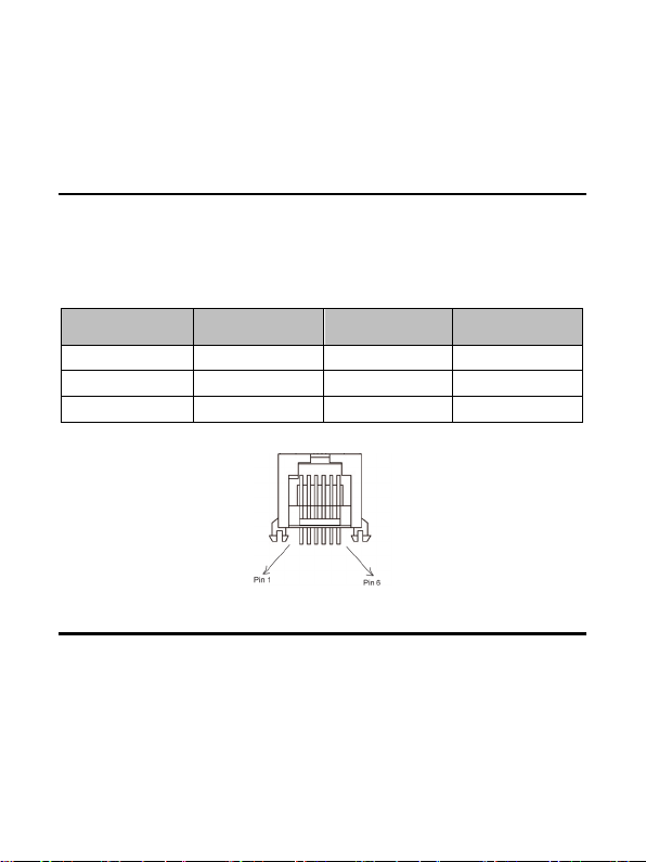
Tab le 1 Pin Function of RJ-11 Jack on HWSP-3SA
Function Type Tip Ring
Line RJ11 Pin3 Pin4
Modem RJ11 Pin3 Pin4
Phone RJ11 Pin3 Pin4
Figure 1 Pin assignment of RJ-11 jack
2 Mounting
Step 1 Fix on the wall.
If you decide to fix the splitter on the wall, please
Drill two holes of 5×30mm on the proper position on the wall.
Where is convenient for cabling the ADSL modem, computer and Telephone
devices. The distance between two holes must be 67mm.
Drive a fish-like anchor into each hole by hammer.
1
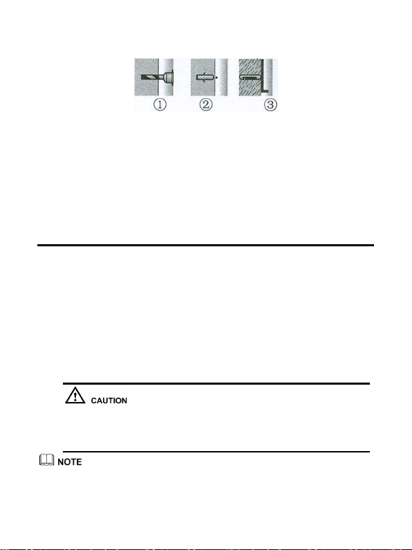
Figure 2 Wall -mount Installati on
To reduce the risk of fire use only No.26 AWG or Larger telecommunication
Put HWSP-3SA on the position, align the mounting holes of the splitter with two
anchor holes, and fix the splitter on the wall with two screws.
Step 2 Hang on wal l.
Drill two holes and drive the fish-like anchor the same like Step 1 but the
distance between two holes must be 27mm. Drive the screws in the anchors as
the support screws.
Make the screw caps 12mm protruded from the wall-surface.
Hang the splitter on the support screws with the hanging hole on back cover of
the splitter.
3 Connection
RJ-11 jack and 6-hole terminal block are connected in parallel and allow either to be
used for installation.
Step 1 Locate Tip (Green) and Ring (Red) from the network interface device (NID)
and disconnect from premises wiring.
Step 2 Connect network side Tip and Ring leads to RJ-11 Connector or terminal on
splitter marked LINE.
Step 3 Connect premise wire to RJ-11 connector or terminal on the splitter marked
PHONE.
Step 4 Connect VDSL equipment to either RJ-11 marked MODEM or the push-pin
terminal.
line record.
If the terminal block is used for the installation, then the ins tall ation s hould
be performed by qualified service personnel .
This Unit is intended for telephone circuit at 150 mA or less and a maximum of 56.6
VDC, ringing voltage not exceed 15V rms.
2
 Loading...