

Page 1

AP7052DN
Hardware Installation and
Maintenance Guide
Issue
01
Date
2017-12-29
HUAWEI TECHNOLOGIES CO., LTD.
Page 2

Issue 01 (2017-12-29)
Huawei Proprietary and Confidential
Copyright © Huawei Technologies Co., Ltd.
i
Copyright © Huawei Technologies Co., Ltd. 2017. All rights reserved.
No part of this document may be reproduced or transmitted in any form or by any means without prior
written consent of Huawei Technologies Co., Ltd.
Trademarks and Permissions
and other Huawei trademarks are trademarks of Huawei Technologies Co., Ltd.
All other trademarks and trade names mentioned in this document are the property of their respective
holders.
Notice
The purchased products, services and features are stipulated by the contract made between Huawei and
the customer. All or part of the products, services and features described in this document may not be
within the purchase scope or the usage scope. Unless otherwise specified in the contract, all statements,
information, and recommendations in this document are provided "AS IS" without warranties, guarantees or
representations of any kind, either express or implied.
The information in this document is subject to change without notice. Every effort has been made in the
preparation of this document to ensure accuracy of the contents, but all statements, information, and
recommendations in this document do not constitute a warranty of any kind, express or implied.
Huawei Technologies Co., Ltd.
Address:
Huawei Industrial Base
Bantian, Longgang
Shenzhen 518129
People's Republic of China
Website:
http://e.huawei.com
Page 3
AP7052DN&AP7152DN
Hardware Installation and Maintenance Guide
About This Document
Issue 01 (2017-12-29)
Huawei Proprietary and Confidential
Copyright © Huawei Technologies Co., Ltd.
ii
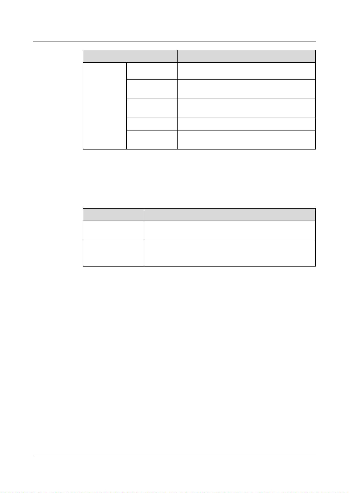
Overview
Symbol
Description
Indicates an imminently hazardous situation
which, if not avoided, will result in death or
serious injury.
Indicates a potentially hazardous situation
which, if not avoided, could result in death
or serious injury.
Indicates a potentially hazardous situation
which, if not avoided, may result in minor
or moderate injury.
Indicates a potentially hazardous situation
which, if not avoided, could result in
equipment damage, data loss, performance
deterioration, or unanticipated results.
NOTICE is used to address practices not
related to personal injury.
Calls attention to important information,
best practices and tips.
NOTE is used to address information not
related to personal injury, equipment
This document describes hardware features of the AP7052DN and AP7152DN and provides
basic installation methods.
Intended Audience
This document is intended for network engineers responsible for WLAN installation and
maintenance. You should have experience in network device installation and maintenance.
About This Document
Symbol Conventions
The symbols that may be found in this document are defined as follows.
Page 4

AP7052DN&AP7152DN
Hardware Installation and Maintenance Guide
About This Document
Issue 01 (2017-12-29)
Huawei Proprietary and Confidential
Copyright © Huawei Technologies Co., Ltd.
iii
Symbol
Description
damage, and environment deterioration.
Change History
Changes between document issues are cumulative. The latest document issue contains all
changes made in previous issues.
Issue 01 (2017-12-29)
Initial commercial release
Page 5

AP7052DN&AP7152DN
Hardware Installation and Maintenance Guide
Contents
Issue 01 (2017-12-29)
Huawei Proprietary and Confidential
Copyright © Huawei Technologies Co., Ltd.
iv
Contents
About This Document ............................................................................................................... ii
1 Product Overview..................................................................................................................... 1
1.1 Device Structure .................................................................................................................................................... 1
1.2 Indicator Description ............................................................................................................................................. 3
1.3 Basic Specifications ............................................................................................................................................... 4
1.4 Ordering Information ............................................................................................................................................. 5
2 AP Installation .......................................................................................................................... 6
2.1 Preparing for Installation ....................................................................................................................................... 6
2.2 Installation Flowchart ............................................................................................................................................ 8
2.3 Unpacking the Equipment ...................................................................................................................................... 8
2.4 Determining the Installation Position ..................................................................................................................... 9
2.5 Installing an IoT Card ................................ ................................................................................................ ...........10
2.6 Installing the AP ...................................................................................................................................................12
2.6.1 Installing the Device on a Wall ...........................................................................................................................12
2.6.2 Installing the Device on a Ceiling.......................................................................................................................14
2.6.3 Installing the Device on a T-rail..........................................................................................................................15
2.6.4 Installing an AP into a Ceiling ............................................................................................................................16
2.6.5 Removing an AP ................................................................................................................................................18
2.7 Cable Connection .................................................................................................................................................19
2.8 Connecting the Security Lock ...............................................................................................................................22
2.9 Checking the Device After Installation .................................................................................................................. 23
2.10 Powering on the AP ............................................................................................................................................24
3 Logging In to the Device ....................................................................................................... 25
3.1 Logging In to the Device Using STelnet/Telnet .....................................................................................................25
3.2 Logging In to the Device Through the Web System ...............................................................................................27
3.3 Logging In to the Device Through the Console Port ..............................................................................................29
4 Hardware Failures .................................................................................................................. 32
4.1 A Device Fails to Be Powered On .........................................................................................................................32
5 Appendix ................................................................................................................................. 35
5.1 On-site Cable Assembly and Installation ...............................................................................................................35
5.1.1 Cable Assembly Precautions ..............................................................................................................................35
Page 6

AP7052DN&AP7152DN
Hardware Installation and Maintenance Guide
Contents
Issue 01 (2017-12-29)
Huawei Proprietary and Confidential
Copyright © Huawei Technologies Co., Ltd.
v
5.1.2 Assembling Power Cables ................................................................................................................................ ..36
5.1.2.1 Assembling a DC 2-Pin Round Connector (A) .................................................................................................36
5.1.2.2 Assembling a DC 2-Pin Round Connector (B) .................................................................................................41
5.1.2.3 Assembling the OT Terminal and Power Cable ................................................................................................48
5.1.2.4 Assembling the JG Terminal and Power Cable .................................................................................................51
5.1.2.5 Assembling the Cord End Terminal and the Power Cable .................................................................................53
5.1.3 Assembling Ethernet Cables ...............................................................................................................................57
5.1.3.1 Assembling the Shielded RJ45 Connector and Ethernet Cable ..........................................................................57
5.1.3.2 Assembling an Optimized Shielded RJ45 Connector and SFTP Network Cables ..............................................62
5.1.3.3 Assembling an Integrated Shielded RJ45 Connector and SFTP Network Cables ................................ ...............67
5.1.3.4 Assembling a Shielded RJ45 Connector and an FTP Network Cable ................................................................71
5.1.3.5 Assembling an Unshielded RJ45 Connector and Ethernet Cable .......................................................................76
5.1.3.6 Checking the Appearance of Contact Strips .....................................................................................................78
5.1.3.7 Testing the Connection of Assembled Cables ...................................................................................................81
5.1.3.8 Common Network Cable Faults and Preventive Measures ...............................................................................84
5.1.4 Assembling Feeders ...........................................................................................................................................85
5.1.4.1 Assembling the Straight Male Coaxial N Connector and the 1/2'' Feeder ..........................................................85
5.1.4.2 Assembling a Straight Male Coaxial N Connector and an RG8U Feeder ..........................................................88
5.1.5 Installing Cable Accessories ...............................................................................................................................94
5.1.5.1 Precautions for Installing Cable Accessories ....................................................................................................94
5.1.5.2 Installing Power Adapters ...............................................................................................................................95
5.1.5.2.1 Installing the OT Terminal............................................................................................................................95
5.1.5.2.2 Installing the Cord End Terminal ..................................................................................................................98
5.1.5.2.3 Installing a 2-Pin Round Connector and a DC Power Cable ..........................................................................99
5.1.5.3 Installing Ethernet Adapters .......................................................................................................................... 103
5.1.5.3.1 Installing a Shielded Ethernet Connector .................................................................................................... 103
5.1.5.3.2 Installing an Unshielded Ethernet Connector .............................................................................................. 104
5.1.5.4 Installing Fiber Connectors ................................ ........................................................................................... 106
5.1.5.4.1 Cleaning Fiber Connectors ......................................................................................................................... 106
5.1.5.4.2 Installing an FC Fiber Connector ................................................................................................................ 107
5.1.5.4.3 Installing an LC Fiber Connector ................................................................................................................ 108
5.1.5.4.4 Installing the SC Fiber Connector ................................ ............................................................................... 110
5.1.5.4.5 Installing an MPO Connector ..................................................................................................................... 111
5.1.6 Replacing the Mold of the Crimping Tool......................................................................................................... 113
5.2 Environmental Requirements for Device Operation ............................................................................................. 116
5.2.1 Environmental Requirements for an Equipment Room ..................................................................................... 116
5.2.1.1 Requirements for Selecting a Site for an Equipment Room ............................................................................ 116
5.2.1.2 Equipment Room Layout .............................................................................................................................. 117
5.2.1.3 Construction Requirements for the Equipment Room .................................................................................... 118
5.2.1.4 Equipment Room Environment ..................................................................................................................... 119
5.2.1.5 Requirements for Corrosive Gases ................................................................................................................ 120
5.2.1.6 Requirements for ESD Prevention ................................................................................................................. 121
Page 7

AP7052DN&AP7152DN
Hardware Installation and Maintenance Guide
Contents
Issue 01 (2017-12-29)
Huawei Proprietary and Confidential
Copyright © Huawei Technologies Co., Ltd.
vi
5.2.1.7 Electromagnetism Requirements for the Equipment Room ............................................................................ 121
5.2.1.8 Requirements for Lightning Proof Grounding ................................................................................................ 121
5.2.2 Requirements for Power Supply ....................................................................................................................... 123
5.2.2.1 Requirements for AC Power Supply .............................................................................................................. 123
5.2.2.2 Recommendations for AC Power Supply ....................................................................................................... 124
5.2.2.3 Requirements for DC Power Supply .............................................................................................................. 124
5.2.2.4 Recommendations for DC Power Supply ....................................................................................................... 125
5.3 Equipment Grounding Specifications .................................................................................................................. 126
5.3.1 General Grounding Specifications .................................................................................................................... 126
5.3.2 Grounding Specifications for an Equipment Room ........................................................................................... 126
5.3.3 Grounding Specifications for Devices .............................................................................................................. 126
5.3.4 Grounding Specifications for Communications Power Supply .......................................................................... 127
5.3.5 Grounding Specifications for Signal Cables...................................................................................................... 127
5.3.6 Specifications for Laying Out Grounding Cables .............................................................................................. 128
5.4 Engineering Labels for Cables ............................................................................................................................ 128
5.4.1 Introduction to Labels ...................................................................................................................................... 129
5.4.1.1 Label Materials ............................................................................................................................................. 129
5.4.1.2 Type and Structure ........................................................................................................................................ 129
5.4.1.3 Label Printing ............................................................................................................................................... 131
5.4.1.4 Writing Labels .............................................................................................................................................. 133
5.4.1.5 Attaching Labels ........................................................................................................................................... 134
5.4.1.6 Contents of Engineering Labels ..................................................................................................................... 136
5.4.1.7 Precautions for Using Engineering Labels ..................................................................................................... 137
5.4.2 Engineering Labels for Optical Fibers .............................................................................................................. 137
5.4.2.1 Labels for the Optical Fibers Connecting Devices .......................................................................................... 137
5.4.2.2 Labels for the Optical Fibers Connecting the Device and an ODF .................................................................. 138
5.4.3 Engineering Labels for Network Cables ........................................................................................................... 140
5.4.4 Engineering Labels for User Cables ................................................................................................................. 141
5.4.5 Engineering Labels for Power Cables ............................................................................................................... 142
5.4.5.1 Engineering Labels for DC Power Cables ...................................................................................................... 142
5.4.5.2 Engineering Labels for AC Power Cables ...................................................................................................... 144
5.5 Guide to Using Optical Modules ................................................................................................ ......................... 145
5.6 Fault Tag ............................................................................................................................................................ 148
5.7 Installation Checklist .......................................................................................................................................... 149
5.8 Guide to Making Drip Loops .............................................................................................................................. 156
5.9 Power Adaptation Solution ................................................................................................................................. 158
Page 8

AP7052DN&AP7152DN
Hardware Installation and Maintenance Guide
1 Product Overview
Issue 01 (2017-12-29)
Huawei Proprietary and Confidential
Copyright © Huawei Technologies Co., Ltd.
1
About This Chapter
Model
Appearance
The AP7052DN and AP7152DN have the following advantages:
4x4 MU-MIMO
Good service support capabilities
High reliability
High security
Simple network deployment
Automatic AC discovery and configuration
Real-time management and maintenance
1 Product Overview
In compliance with IEEE 802.11ac, the AP7052DN and AP7152DN support a theoretical rate
of up to 3.46 Gbit/s, greatly improving wireless user experience.
The AP7052DN and AP7152DN provide highest-quality wireless services for mobile office,
high-density scenarios, elementary education, and higher education. They can be flexibly
deployed in different environments.
A cloud AP must be used together with a cloud server.
1.1 Device Structure
1.2 Indicator Description
1.3 Basic Specifications
1.4 Ordering Information
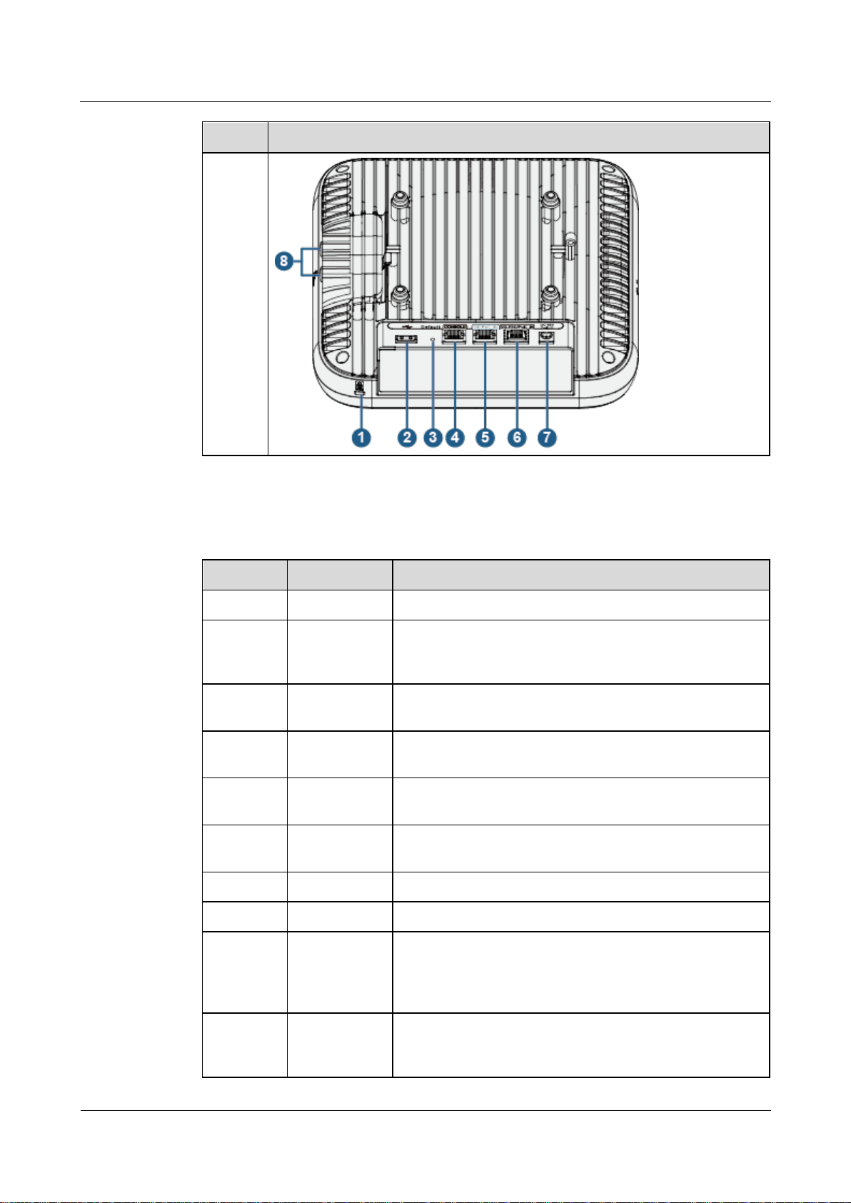
1.1 Device Structure
Table 1-1 shows the appearance of the AP7052DN and AP7152DN.
Table 1-1 Appearance of the AP
Page 9
AP7052DN&AP7152DN
Hardware Installation and Maintenance Guide
1 Product Overview
Issue 01 (2017-12-29)
Huawei Proprietary and Confidential
Copyright © Huawei Technologies Co., Ltd.
2
Model
Appearance
AP7052
DN
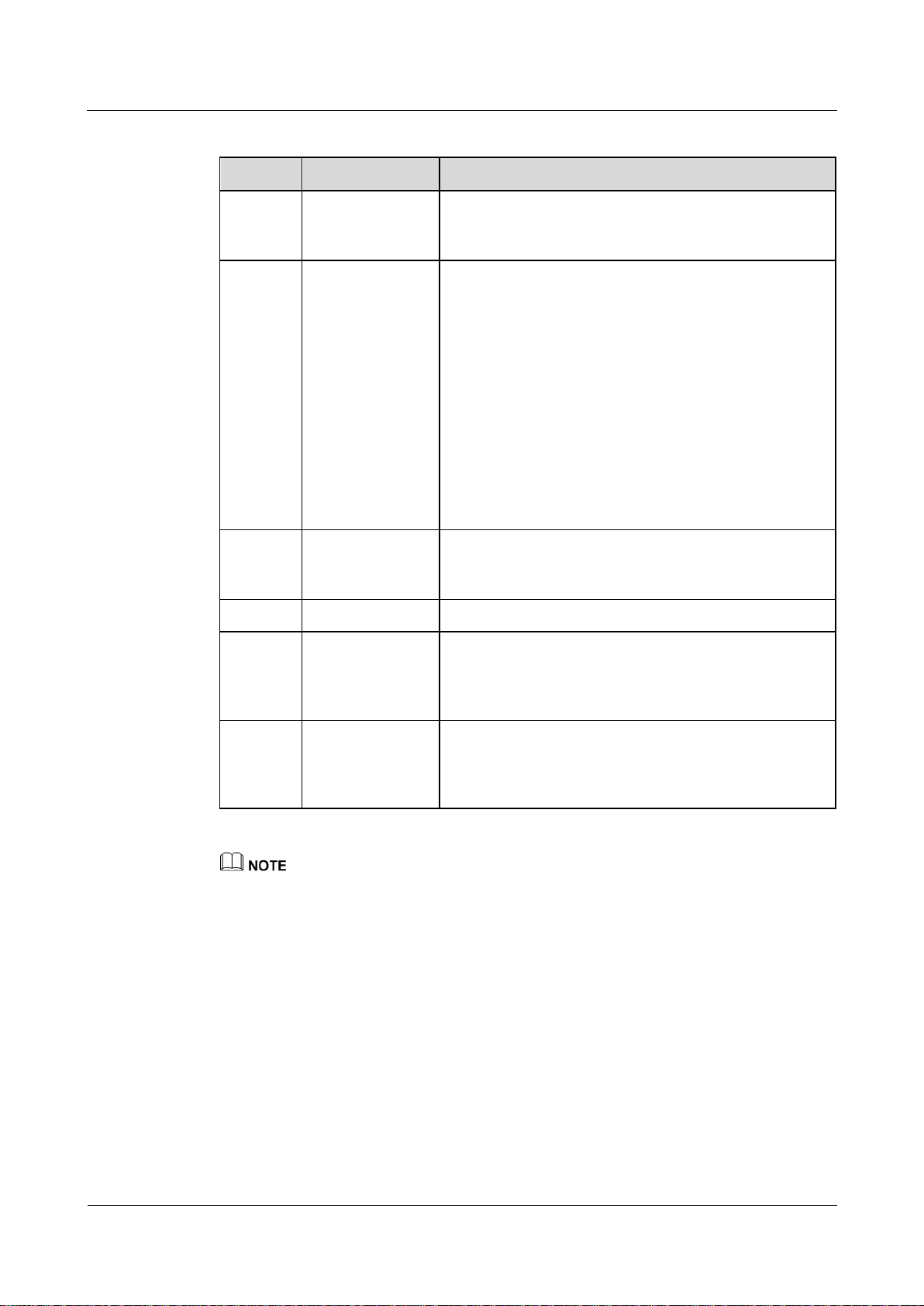
No.
Name
Description
1
Security slot
Connects to a security lock.
2
USB port
Connects to a USB flash drive or other storage devices to
extend the storage space of the AP. The USB2.0 standard is
supported.
3
Default
Restores factory settings and restarts the device when you
hold down the button more than 3 seconds.
4
CONSOLE
Connects to a maintenance terminal for AP configuration
and management.
5
GE/PoE_IN
10/100/1000M port that connects to the wired Ethernet and
supports PoE input.
6
5/2.5GE/PoE_
IN
100M/1000M/2.5G/5G port that connects to the wired
Ethernet and supports PoE input.
7
DC 48V
Connects a power adapter to the AP.
8
Radio port
Connects an antenna to an IoT card through a radio cable.
9
2.4G/5G
Connects a 2.4 GHz or 5 GHz antenna to the AP to send
and receive wireless signals.The port type is
RP-SMA-K.The port is applicable only to an AP that
supports external antennas.
10
5G
Connects a 5 GHz antenna to the AP to send and receive
wireless signals.The port type is RP-SMA-K.The port is
applicable only to an AP that supports external antennas.
Table 1-2 describes ports on the AP7052DN
Table 1-2 Interface description
Page 10
AP7052DN&AP7152DN
Hardware Installation and Maintenance Guide
1 Product Overview
Issue 01 (2017-12-29)
Huawei Proprietary and Confidential
Copyright © Huawei Technologies Co., Ltd.
3
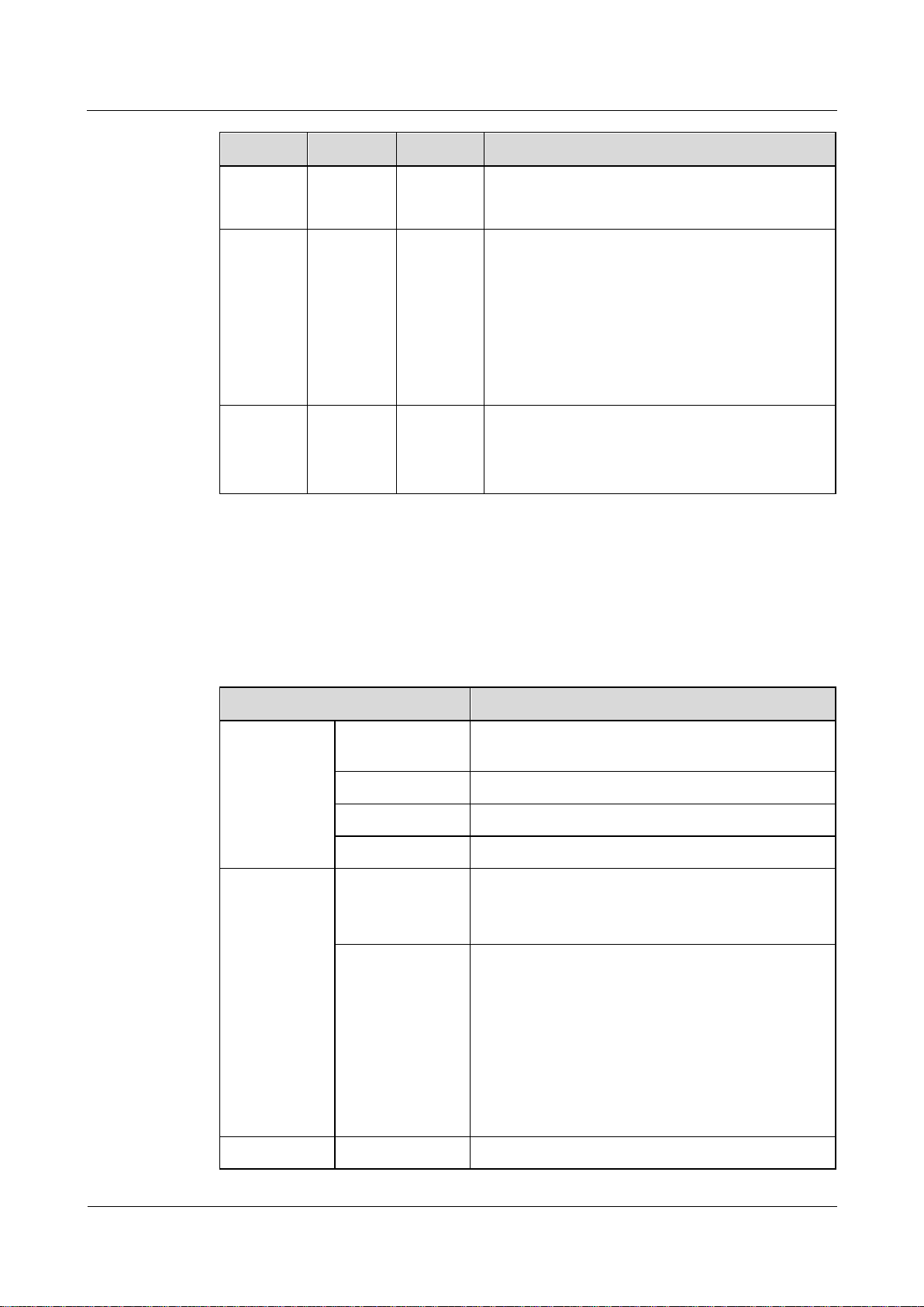
Type
Color
Status
Description
Default
status
after
power-on
Green
Steady on
The AP is just powered on and the software is not
started yet.
Software
startup
status
Green
Steady on
after
blinking
once
After the system is reset and starts uploading the
software, the indicator blinks green once. Until the
software is uploaded and started, the indicator
remains steady green.
Running
status
Green
Blinking
once
every 2s
(0.5 Hz)
The system is running properly, the Ethernet
connection is normal, and STAs are associated
with the AP.
The system enters the Uboot CLI.
Blinking
The system is running properly, the Ethernet
The AP supports the following power supply modes: PoE power supply and DC power supply.
When the AP uses the DC power supply, use a power adapter for power supply; otherwise, the AP
may be damaged.
For power adapter models, see 5.9 Power Adaptation Solution.
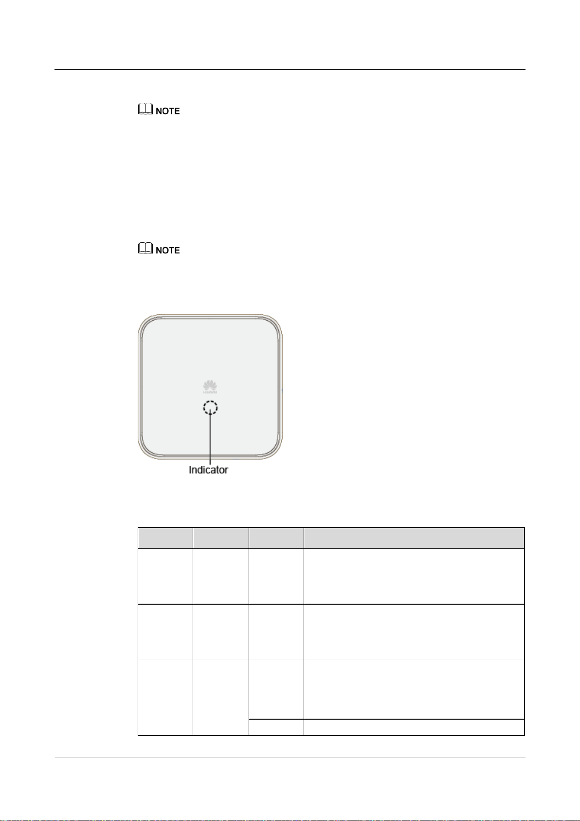
1.2 Indicator Description
The AP7052DN and AP7152DN provide only a single indicator, as shown in Figure 1-1.
The indicator is located inside the panel, which turns on after the AP is powered on.
Indicator colors may vary slightly at different temperature.
Figure 1-1 Indicator
Table 1-3 Description about the single indicator
Page 11
AP7052DN&AP7152DN
Hardware Installation and Maintenance Guide
1 Product Overview
Issue 01 (2017-12-29)
Huawei Proprietary and Confidential
Copyright © Huawei Technologies Co., Ltd.
4
Type
Color
Status
Description
once
every 5s
(0.2 Hz)
connection is normal, and no STA is associated
with the AP. The system is in low power
consumption state.
Alarm
Green
Blinking
once
every
0.25s (4
Hz)
The software is being upgraded.
After the software is loaded and started, the AP
requests to go online if it works in Fit AP or
cloud-based management mode. The indicator
remains in this state before the AP successfully
goes online.
The AP works in Fit AP or cloud-based
management mode and fails to go online.
Fault
Red
Steady on
A fault that affects services has occurred, such as a
DRAM detection failure or system software
loading failure. The fault cannot be automatically
rectified and must be rectified manually.
Item
Description
Physical
specifications
Dimensions (H x
W x D)
52 mm × 220 mm × 220 mm
Weight AP7052DN: 1.68 kg
System memory
512 MB DDR3L
FLASH
16 MB NOR FLASH + 128 MB NAND FLASH
Power
specifications
Power input
DC: 42.5 V to 57 V
PoE power supply: in compliance with IEEE
802.3at/bt
Maximum power
consumption
DC/802.3bt power supply: 33 W (excluding the
output power of the USB port)
802.3at power supply: 25.5 W (The USB function
is unavailable. The port rate of 5/2.5GE/PoE_IN
decreases to 2.5 Gbit/s. The IoT card power is
lower than 0.5 W.)
NOTE
The actual maximum power consumption depends on local
laws and regulations.
Environment
Operating
-60 m to +1800 m: -10°C to +50°C
1.3 Basic Specifications
Table 1-4 provides basic specifications of the AP7052DN and AP7152DN.
Table 1-4 Basic specifications
Page 12
AP7052DN&AP7152DN
Hardware Installation and Maintenance Guide
1 Product Overview
Issue 01 (2017-12-29)
Huawei Proprietary and Confidential
Copyright © Huawei Technologies Co., Ltd.
5
Item
Description
specifications
temperature
1800 m to 5000 m: Temperature decreases by
1°C every time the altitude increases 300 m.
Storage
temperature
-40°C to +70°C
Operating
humidity
5% to 95% (non-condensing)
IP rating
IP41
Atmospheric
pressure
53 kPa to 106 kPa
Part Number
Description
02351KDV
AP7052DN Mainframe(11ac Wave2,Indoor,4X4 Dual-Band,IoT
Expansion,Built-in Antenna)
02351KEA
AP7052DN-USA Mainframe(11ac Wave2,Indoor,4X4
Dual-Band,IoT Expansion,Built-in Antenna,United States
dedicated)
1.4 Ordering Information
To place an order, contact technical support personnel.
Page 13

AP7052DN&AP7152DN
Hardware Installation and Maintenance Guide
2 AP Installation
Issue 01 (2017-12-29)
Huawei Proprietary and Confidential
Copyright © Huawei Technologies Co., Ltd.
6
About This Chapter
2.1 Preparing for Installation
2.2 Installation Flowchart
2.3 Unpacking the Equipment
2 AP Installation
2.4 Determining the Installation Position
2.5 Installing an IoT Card
2.6 Installing the AP
2.7 Cable Connection
2.8 Connecting the Security Lock
2.9 Checking the Device After Installation
2.10 Powering on the AP
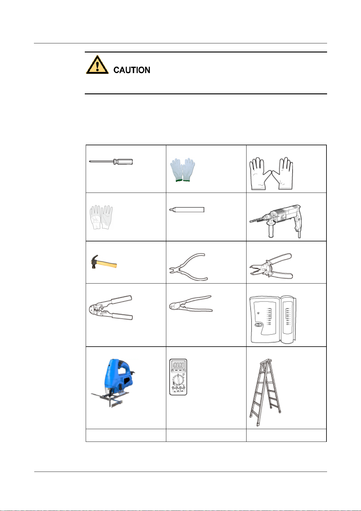
2.1 Preparing for Installation
This section describes safety precautions and tool preparations for AP installation.
Safety Precautions
Take proper measures to prevent injuries and device damage.
Place the device in a dry and flat position away from any liquid and prevent the device
from slipping.
Keep the device clean.
Do not put the device and tools in the aisles.
Page 14
AP7052DN&AP7152DN
Hardware Installation and Maintenance Guide
2 AP Installation
Issue 01 (2017-12-29)
Huawei Proprietary and Confidential
Copyright © Huawei Technologies Co., Ltd.
7
Only the qualified personnel are permitted to install and remove the device and its accessories.
Phillips screwdriver
Protective gloves
ESD gloves
Slip-proof glove
Marker
Hammer drill
Claw hammer
Diagonal pliers
Wire stripper
RJ45 crimping tool
Cable cutter
Network cable tester
Jig saw
Multimeter
Ladder
Safety helmet
Safety belt
Anti-skid shoes
Before installation and operation, read the safety precautions carefully.
Tool Preparation
To install APs, prepare tools listed in Table 2-1.
Table 2-1 Tools
Page 15
AP7052DN&AP7152DN
Hardware Installation and Maintenance Guide
2 AP Installation
Issue 01 (2017-12-29)
Huawei Proprietary and Confidential
Copyright © Huawei Technologies Co., Ltd.
8
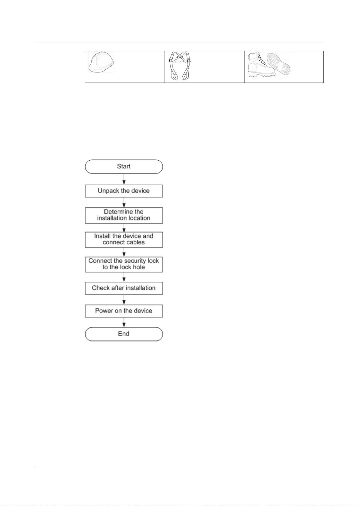
2.2 Installation Flowchart
The following figure shows the process for installing an AP.
Figure 2-1 Installation flowchart
2.3 Unpacking the Equipment
Before unpacking the carton, ensure that the packing carton is intact and not damaged or
soaked. Stop unpacking if the equipment is rusted or soggy. Then, investigate causes and
contact the supplier.
After unpacking, check items in the carton against the packing list. If any item is missing,
contact the supplier or agent.
Usually, the packing list contains the following items.
AP device
Page 16
AP7052DN&AP7152DN
Hardware Installation and Maintenance Guide
2 AP Installation
Issue 01 (2017-12-29)
Huawei Proprietary and Confidential
Copyright © Huawei Technologies Co., Ltd.
9
Sheet metal mounting bracket
Screws
Adjustable buckle
Expansion screws
Quick start guide
Warranty card
MAC address label
SN label
If a PoE adapter or a DC power adapter is required, you need to purchase it separately. For DC power
adapter models, see 5.9 Power Adaptation Solution.
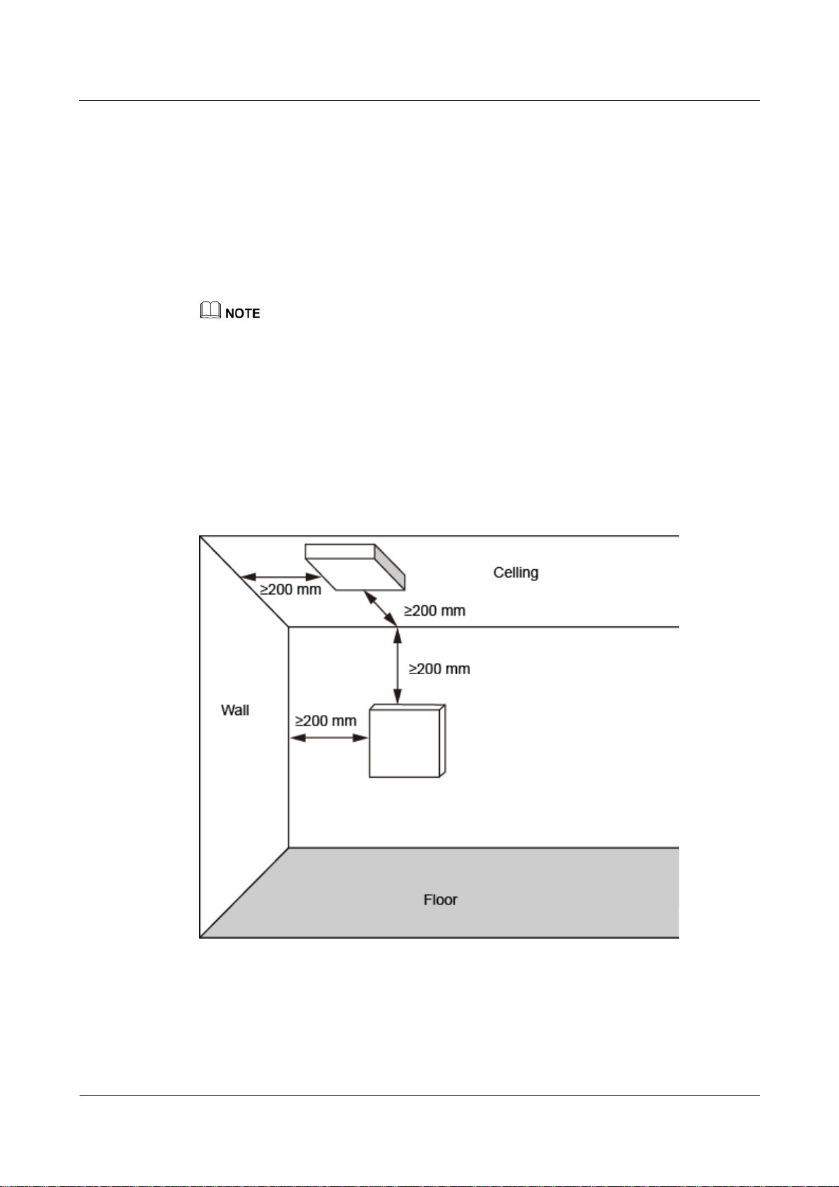
2.4 Determining the Installation Position
Indoor APs are usually mounted on a wall or ceiling using sheet metal mounting brackets. The
installation position is determined by the site survey. There must be at least 200 mm clearance
between the cabling end of the AP and the wall. Figure 2-2 shows space requirements.
Figure 2-2 Mounting an AP
When determining the AP installation position, comply with the following rules:
Try to reduce the number of obstacles, such as walls, between the AP and user terminals.
Page 17
AP7052DN&AP7152DN
Hardware Installation and Maintenance Guide
2 AP Installation
Issue 01 (2017-12-29)
Huawei Proprietary and Confidential
Copyright © Huawei Technologies Co., Ltd.
10
Scenario
Deployment Distance Requirement
Indoor
installation
There should be at least a 7 m distance between antennas.
The antennas should be placed at least 2 m from the 4G antennas of
the carrier.
The antennas should be placed far away from electronic devices that
may produce interference, such as microwave ovens.
Place the AP far away from electronic devices that may produce radio interference, such
as microwave ovens, other APs, antennas, and other radio communication devices. For
details, see Table 2-2.
Install the AP in a hidden position that does not affect daily lives and work of residents.
Install the AP in a site that is free from leaking or dripping water, heavy dew, and
humidity, and take protective measures to prevent water from flowing into the equipment
along the cable.
Do not install the AP in an environment with high temperature, dust, poisonous gases,
flammable or explosive objects, electromagnetic interference (from a radar station, radio
station, or substation), unstable voltage, violent shakes, or strong noise.
Table 2-2 General anti-interference requirements
If antennas are embedded into APs, the deployment distance requirements on the antennas are those on
APs.
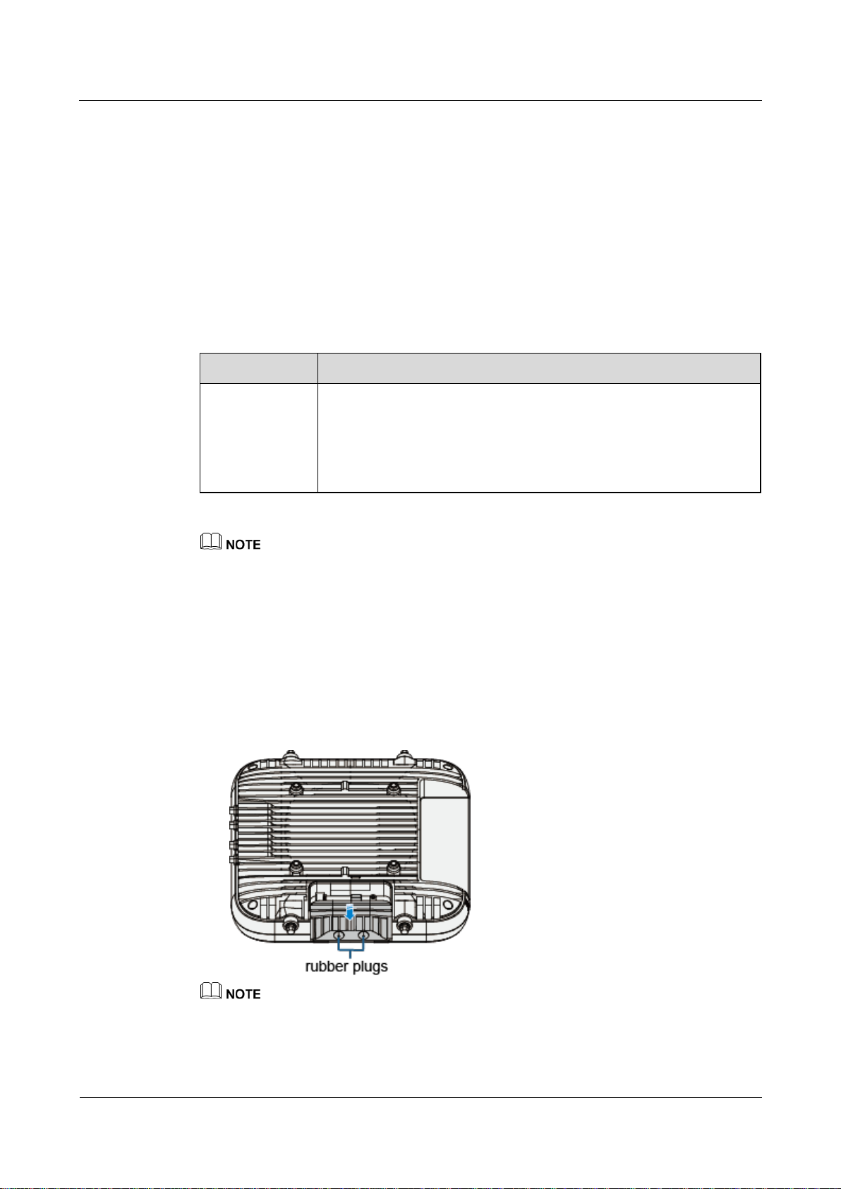
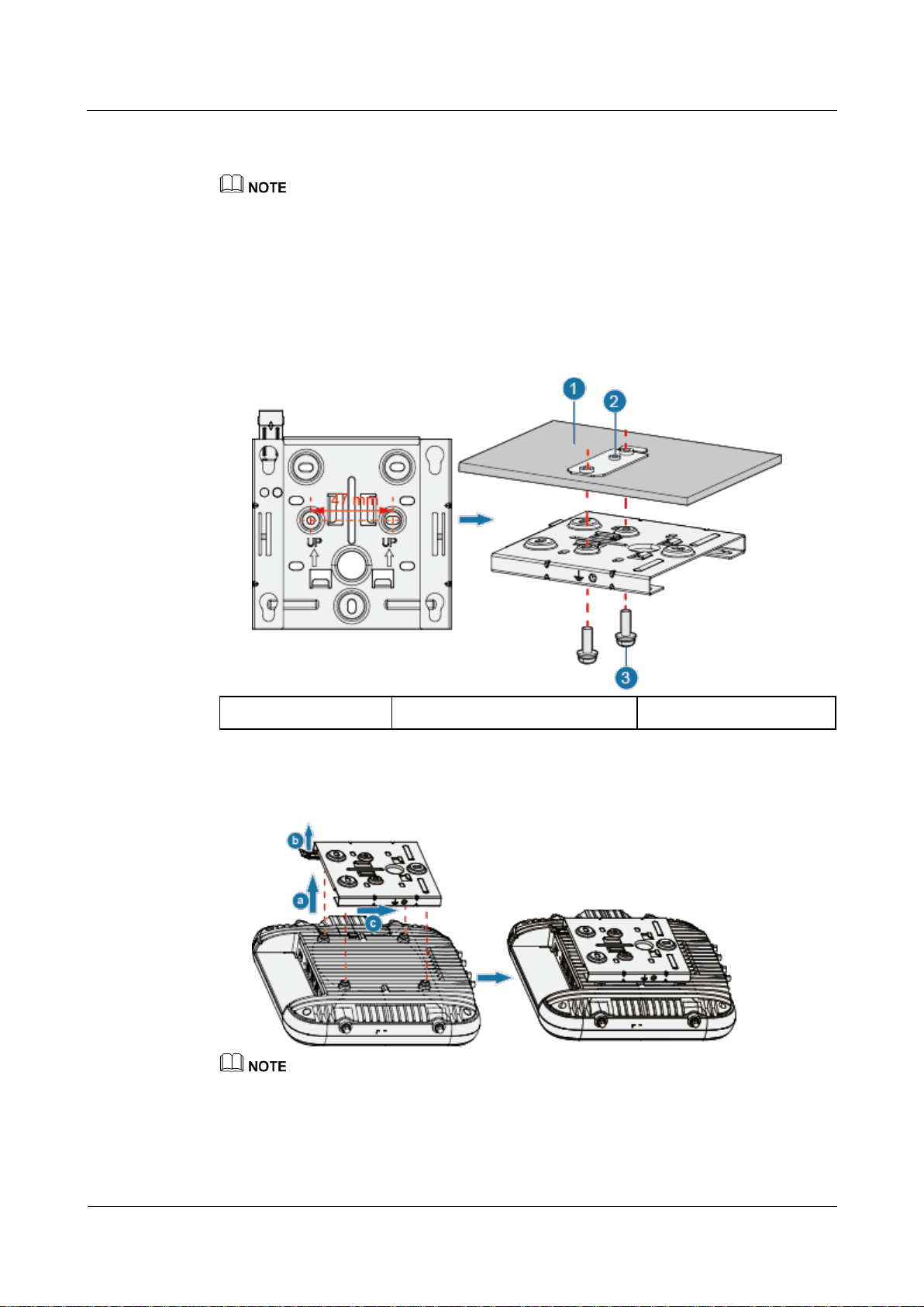
2.5 Installing an IoT Card
The AP provides an IoT slot for installing an ANT or RFID card based on customer
requirements.
1. Hold the buckle on the bottom cover of the AP, and remove the cover and plastic plugs.
The number of rubber plugs to be removed depends on the number of radio cables.
Use a flat-head screwdriver to remove the cover. Insert the flat-head screwdriver under the cover buckle
and lever the buckle.
Page 18
AP7052DN&AP7152DN
Hardware Installation and Maintenance Guide
2 AP Installation
Issue 01 (2017-12-29)
Huawei Proprietary and Confidential
Copyright © Huawei Technologies Co., Ltd.
11
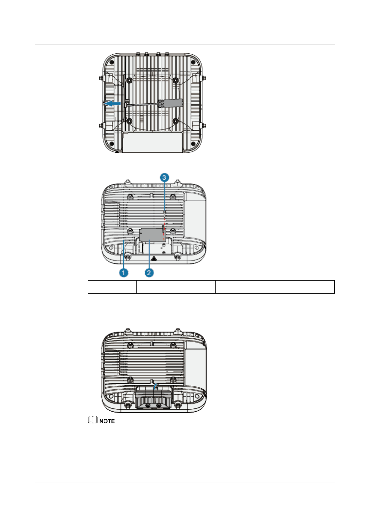
1. AP
2. IoT card
3. M2.5x6 screws
2. Place an IoT card in the slot and tighten the card using M2.5x6 screws (with a tightening
torque of 0.3 Nm).
3. Connect an IoT antenna with the MMCX connector of an IoT card, and slide the IoT
card cover to secure the IoT card. When installing the IoT card cover, insert the
protrusion on the cover into the opening on the AP. Then press the protrusion until you
hear a click sound.
The diagonal size of a hexagon SMA connector must be less than or equal to 8 mm; otherwise, the
cable cannot be installed.
The ANT card has one radio port, and the RFID card has two.
Page 19
AP7052DN&AP7152DN
Hardware Installation and Maintenance Guide
2 AP Installation
Issue 01 (2017-12-29)
Huawei Proprietary and Confidential
Copyright © Huawei Technologies Co., Ltd.
12
2.6 Installing the AP
2.6.1 Installing the Device on a Wall
A wall for installing the device needs to meet the following requirements:
The wall can bear the weight of four times the total weight of the device and mounting bracket
without damage.
When the tightening torx of a screw reaches 5 N•m, the screw still properly works, without crack or
damage on the wall.
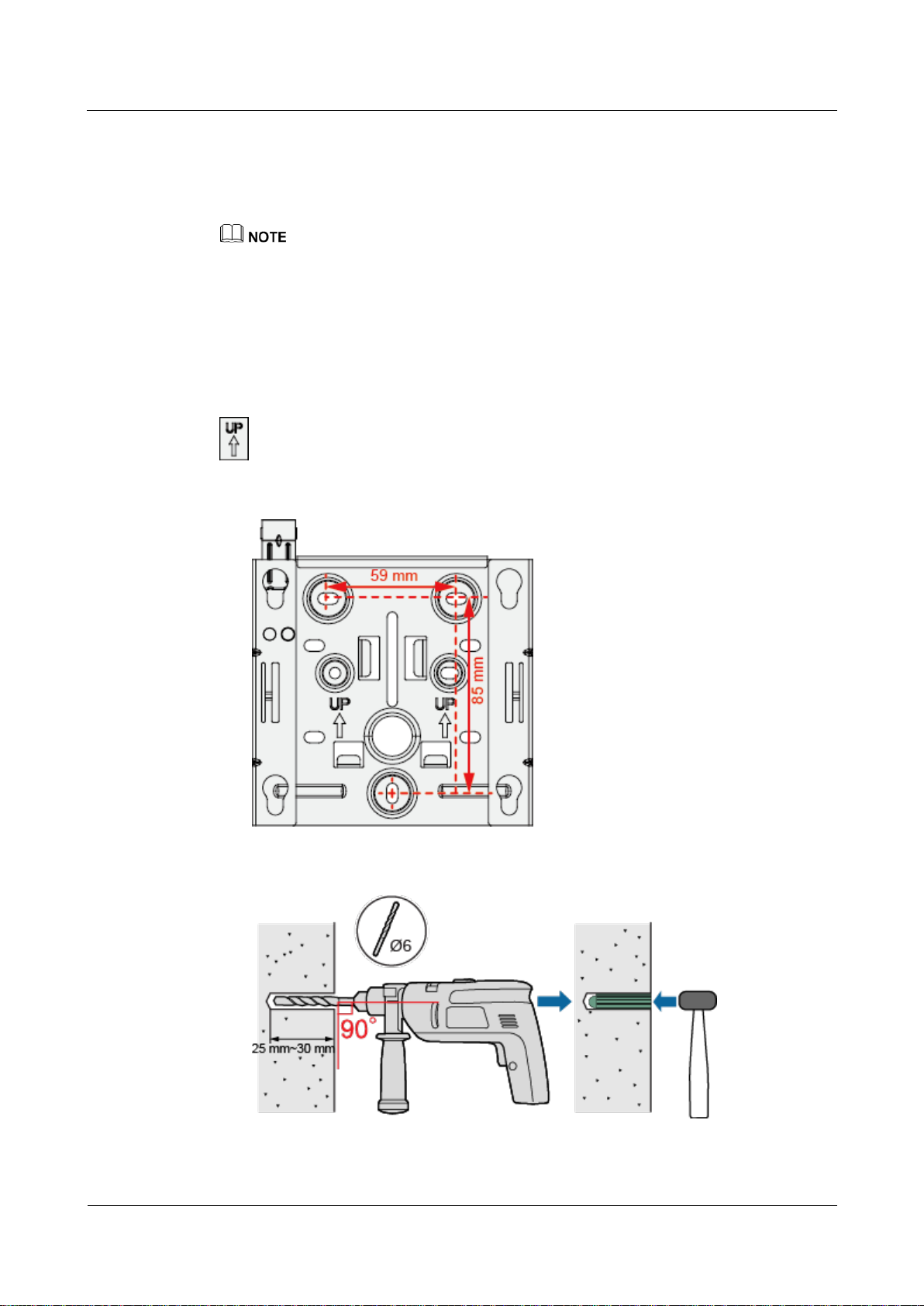
Mounting kits and expansion bolts are required to install the AP on a wall. The procedures are
as follows:
When fixing the sheet metal mounting bracket, ensure that the arrows point upwards on the
label.
1. Fix a mounting bracket to the wall against the wall and mark the drilling positions
through holes of the bracket.
2. Use a 6 mm drill bit to drill 25 mm to 30 mm deep holes in the drilling positions.
Hammer the expansion tubes into the holes until the expansion tubes are completely
embedded into the wall.
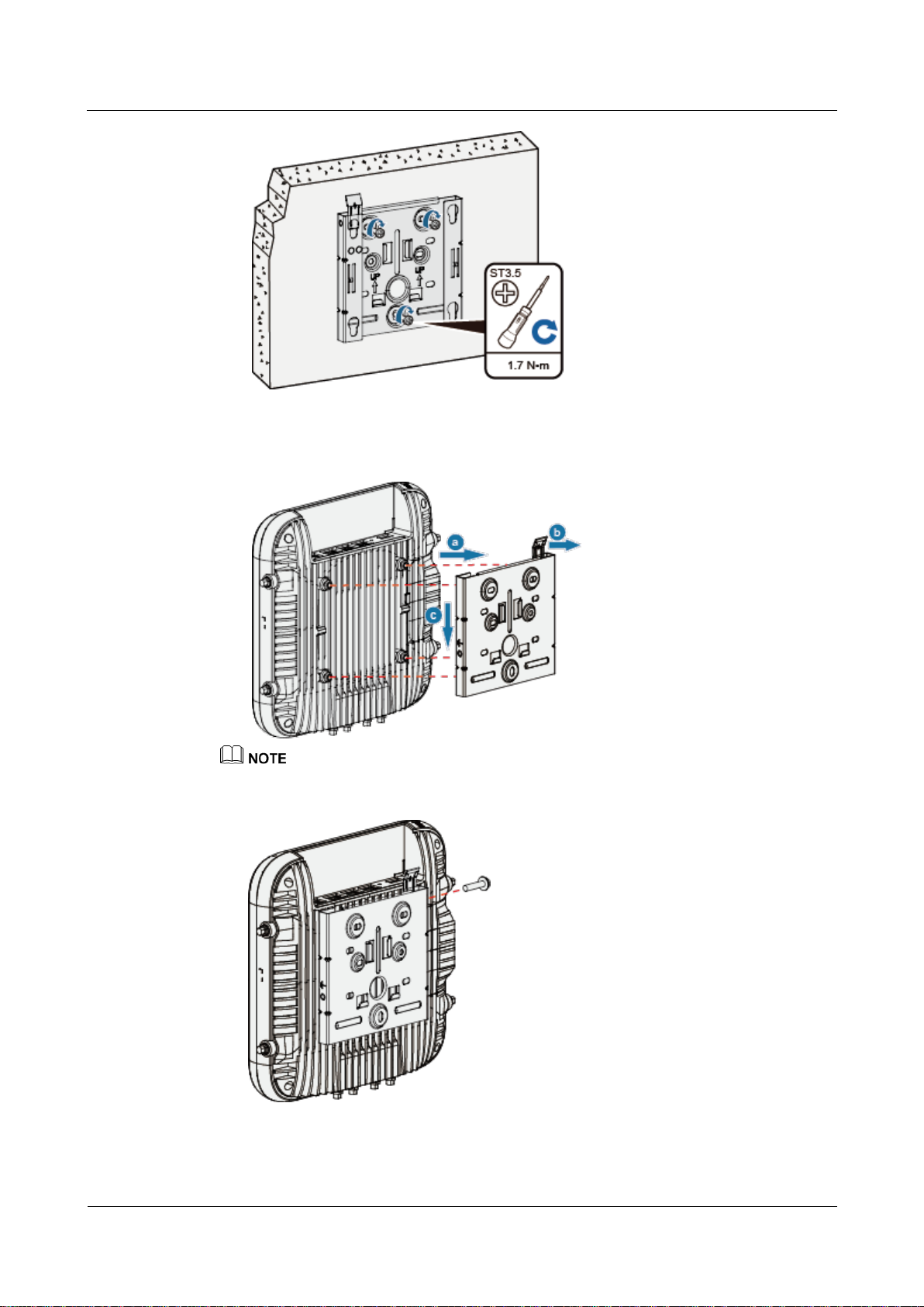
3. Fix the mounting bracket to the wall and use the Phillips screwdriver to fasten three
expansion screws into the expansion tubes.
Page 20
AP7052DN&AP7152DN
Hardware Installation and Maintenance Guide
2 AP Installation
Issue 01 (2017-12-29)
Huawei Proprietary and Confidential
Copyright © Huawei Technologies Co., Ltd.
13
4. Connect the cables. For details, see 2.7 Cable Connection.
5. Align the rubber feet of the device over the mounting slots on the mounting bracket and
vertically push the AP to secure it. When the spring clip is popped up, push the AP
downward until it snaps into place (you can hear a click).
In a scenario with heavy vibrations, tighten the AP to the mounting bracket using M4x30 screws with a
torque of 1.4N•m. This prevents the AP falling off from due to vibrations. In normal scenarios, you do
not need to install these screws.
Page 21
AP7052DN&AP7152DN
Hardware Installation and Maintenance Guide
2 AP Installation
Issue 01 (2017-12-29)
Huawei Proprietary and Confidential
Copyright © Huawei Technologies Co., Ltd.
14
2.6.2 Installing the Device on a Ceiling
1. Ceiling tile
2. Adjustable buckle
3. M4x30 screw
A ceiling needs to bear the weight of four times the total weight of the device and mounting bracket
without damage.
1. Remove a ceiling tile, determine locations of mounting holes based on the distance
between two installation holes on the mounting bracket, use a hammer drill to drill holes
on the ceiling tile, and fix the mounting bracket to the ceiling tile(with a tightening
torque of 1.4 N•m).
The screws provided for ceiling-mounting of APs are 30 mm long and can be used to fix
an AP on a ceiling no thicker than 15 mm. To install APs on thicker ceilings, you need to
purchase longer screws.
2. Connect the cables. For details, see 2.7 Cable Connection.
3. Align the rubber feet of the device over the mounting slots on the mounting bracket and
vertically push the AP to secure it. When the spring clip is popped up, push the AP
horizontally until it snaps into place (you can hear a click).
Ensure that the AP is correctly installed on the mounting bracket and there is 200 mm space above
and around the AP for maintenance.
In a scenario with heavy vibrations, tighten the AP to the mounting bracket using M4x30 screws
with a torque of 1.4N•m. This prevents the AP falling off from due to vibrations. In normal scenarios,
you do not need to install these screws.
Page 22
AP7052DN&AP7152DN
Hardware Installation and Maintenance Guide
2 AP Installation
Issue 01 (2017-12-29)
Huawei Proprietary and Confidential
Copyright © Huawei Technologies Co., Ltd.
15
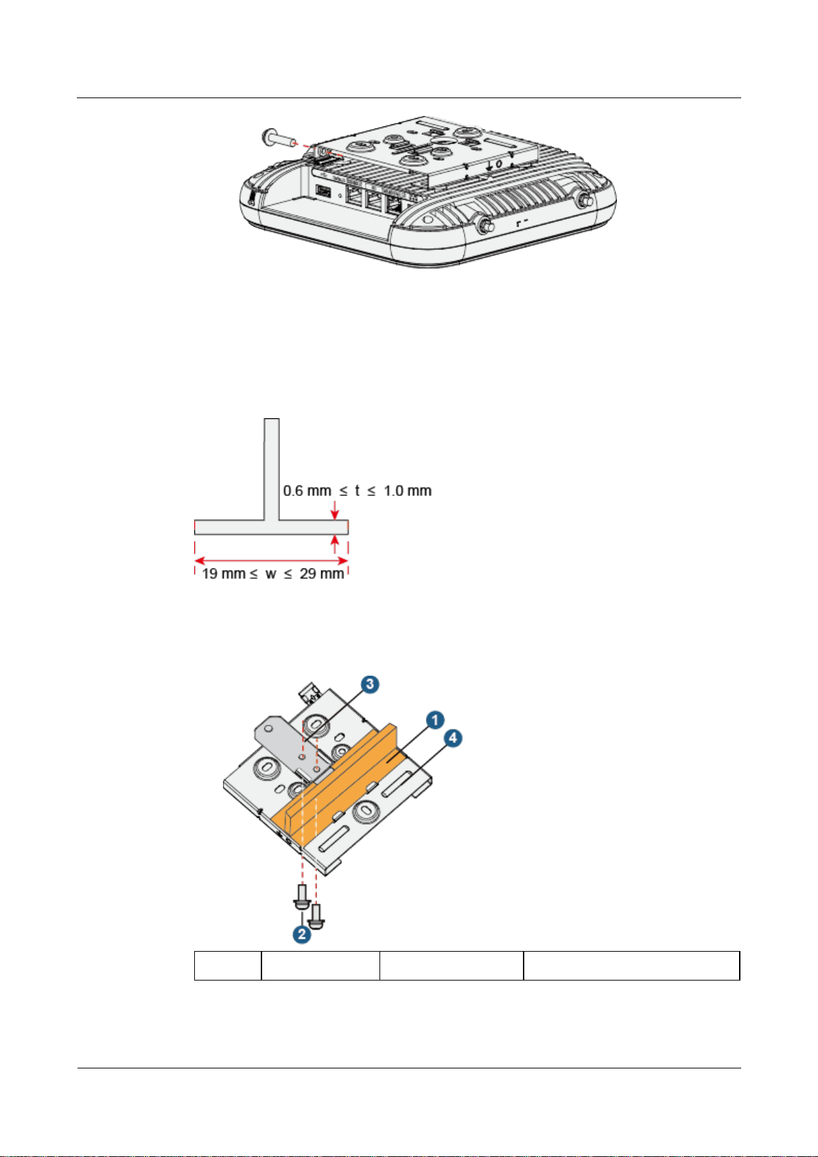
2.6.3 Installing the Device on a T-rail
1. T-rail
2. M4x30 Screw
3. Adjustable buckle
4. Sheet metal mounting bracket
A T-rail needs to bear the weight of four times the total weight of the device and mounting
bracket without damage. Figure 2-3 shows the T-rail dimensions requirements (t: thickness; w:
width).
Figure 2-3 Section of a T-rail
1. Remove two ceiling tiles around the T-rail, use screws to fix the adjustable buckle to the
mounting bracket, hook the adjustable buckle to the T-rail, and secure the screw on the
adjustable buckle to fasten the mounting bracket and T-rail.
2. Connect the cables. For details, see 2.7 Cable Connection.
Page 23
AP7052DN&AP7152DN
Hardware Installation and Maintenance Guide
2 AP Installation
Issue 01 (2017-12-29)
Huawei Proprietary and Confidential
Copyright © Huawei Technologies Co., Ltd.
16
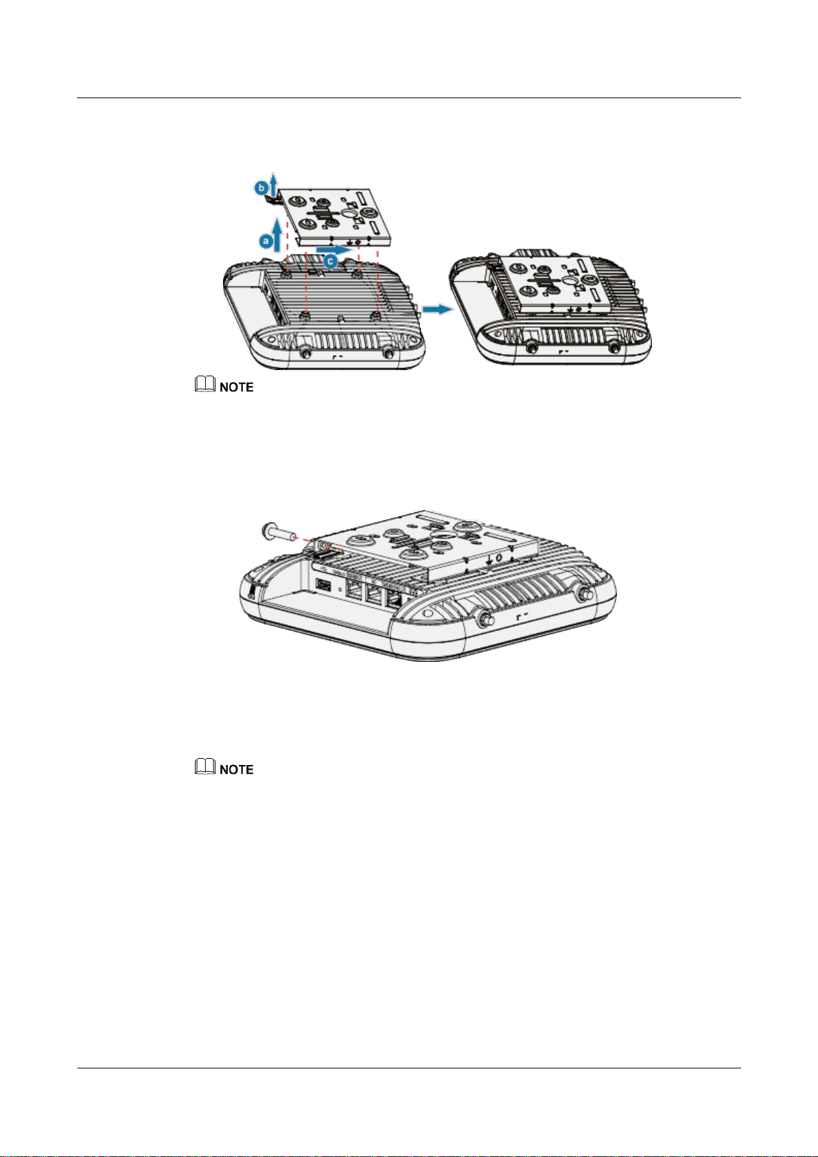
3. Align the rubber feet of the device over the mounting slots on the mounting bracket and
vertically push the AP to secure it. When the spring clip is popped up, push the AP
horizontally until it snaps into place (you can hear a click).
Before fixing the adjustable buckle with a screw, adjust the buckle to a proper position based on the
T-rail width.
Ensure that the AP is correctly installed on the mounting bracket and there is 200 mm space above
and around the AP for maintenance.
In a scenario with heavy vibrations, tighten the AP to the mounting bracket using M4x30 screws
with a torque of 1.4N•m. This prevents the AP falling off from due to vibrations. In normal scenarios,
you do not need to install these screws.
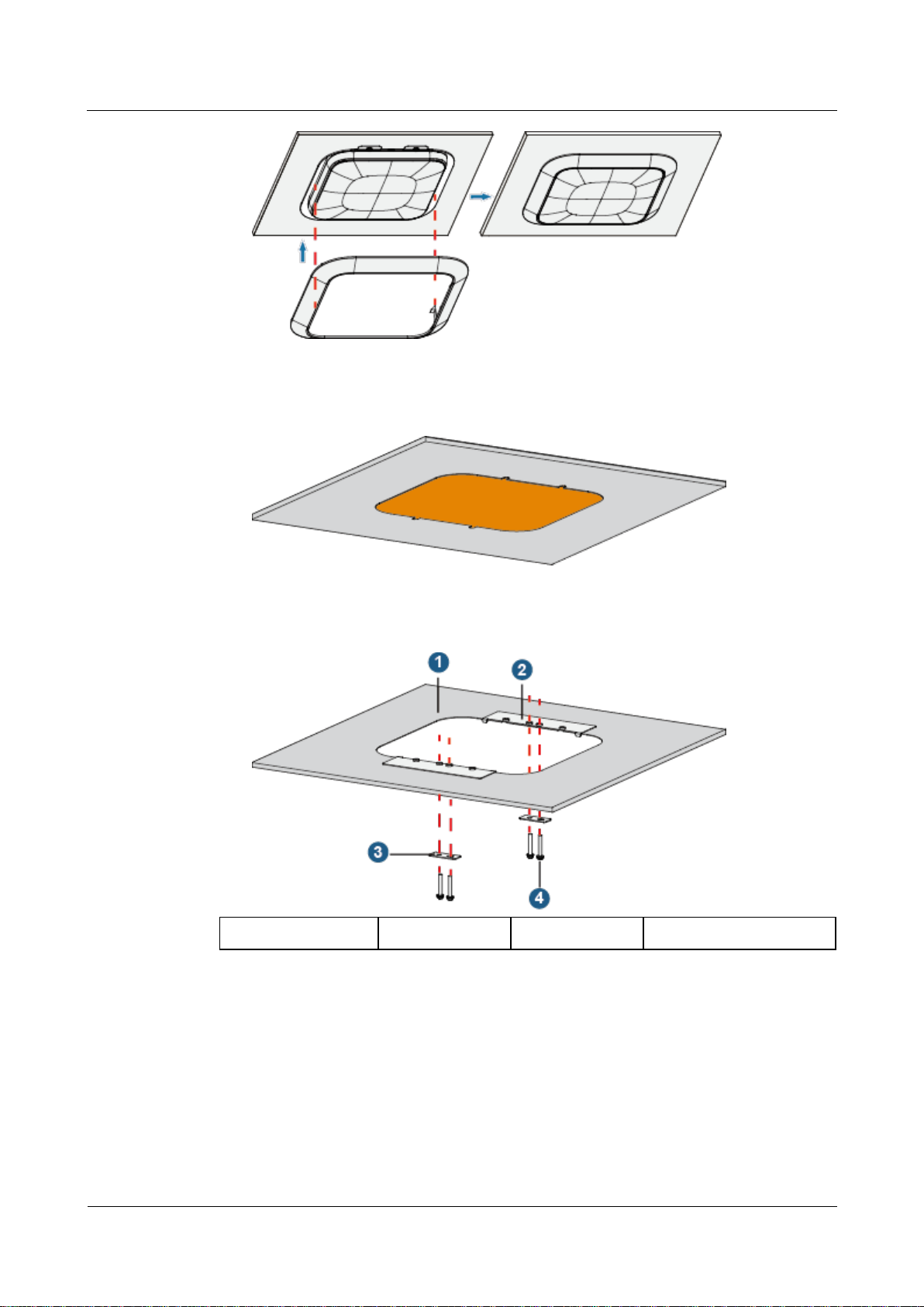
2.6.4 Installing an AP into a Ceiling
An AP can be installed in a removable or irremovable ceiling. For details, see Installing an AP
in a Removable Ceiling and Installing an AP in an Irremovable Ceiling.
This mode is not applicable to the AP with external antennas (including IoT card antennas and AP
antennas).
You need to purchase a plastic enclosure, mounting bracket, and other accessories separately. The
part number is 21242880.
A ceiling needs to bear the weight of four times the total weight of the device and mounting bracket
without damage.
The screws provided for ceiling-mounting of APs are 30 mm long and can be used to fix an AP on a
ceiling no thicker than 15 mm. To install APs on thicker ceilings, you need to purchase longer
screws.
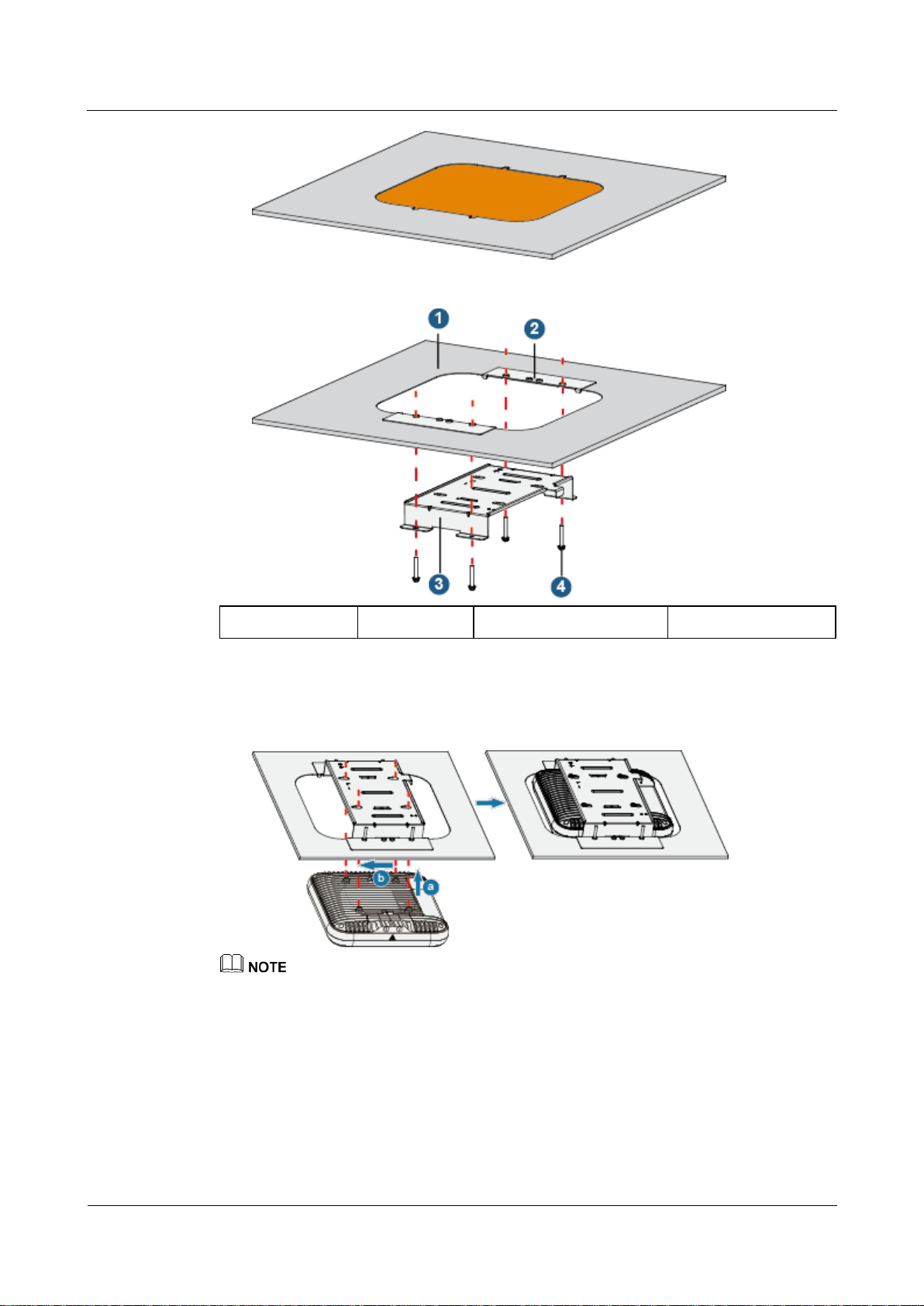
Installing an AP in a Removable Ceiling
1. Remove a ceiling tile, draw the AP mounting position on the ceiling tile using an
opening mold, and cut an opening.
Page 24
AP7052DN&AP7152DN
Hardware Installation and Maintenance Guide
2 AP Installation
Issue 01 (2017-12-29)
Huawei Proprietary and Confidential
Copyright © Huawei Technologies Co., Ltd.
17
1. Ceiling tile
2. Clamp 1
3. Mounting bracket
4. M4x30 screws
2. Use M4x30 screws to tighten the mounting bracket, ceiling tile, and clamp 1 to the
ceiling tile (with a tightening torque of 1.2 Nm).
3. Install the ceiling tile. For details, see Connect the cables. For details, see 2.7 Cable
Connection.
4. Align the rubber feet of the device over the mounting slots on the mounting bracket and
vertically push the AP to secure it. When the spring clip is popped up, push the AP
horizontally until it snaps into place (you can hear a click).
Ensure that the AP's network interfaces point to the same direction as the spring clip of the mounting
bracket. Otherwise, installation cannot continue.
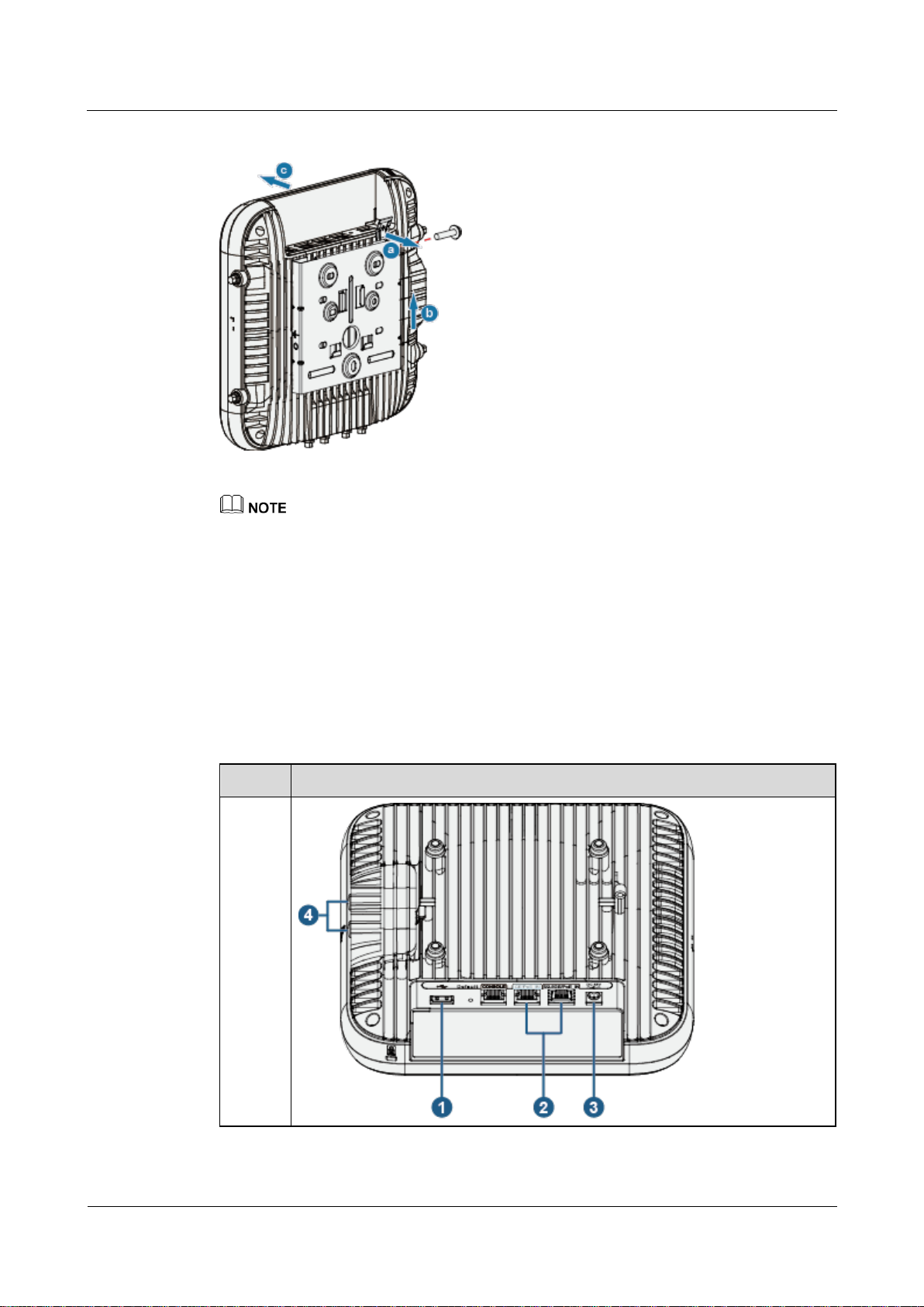
5. Install the plastic enclosure. Ensure that the clamping hook of the enclosure points to the
same direction as the AP's network interfaces. Push the enclosure vertically until the
enclosure surface is aligned with that of the AP (you can hear a click).
Page 25
AP7052DN&AP7152DN
Hardware Installation and Maintenance Guide
2 AP Installation
Issue 01 (2017-12-29)
Huawei Proprietary and Confidential
Copyright © Huawei Technologies Co., Ltd.
18
Installing an AP in an Irremovable Ceiling
1. Ceiling tile
2. Clamp 1
3. Clamp 2
4. M4x30 screws
1. Draw the AP mounting position on the ceiling tile using an opening mold and cut an
opening.
2. Use clamp 1 to align with the dent of the opening on the ceiling tile and mark the two
holes in the middle of clamp 1. Drill two holes with a diameter of 5 mm on both sides of
the opening on the ceiling tile. Use four M4x30 screws to tighten clamps 1 and 2 to the
ceiling tile (with a tightening torque of 1.2 Nm).
3. Install the mounting bracket, cables, AP, and enclosure. For details, see steps 2, 3, 4, and
5 in Installing an AP in a Removable Ceiling.
2.6.5 Removing an AP
Flip the spring clip on the mounting bracket and slip the AP towards the spring clip. Release
the spring clip until the rubber feet of the AP enter the mounting keyholes. Remove the AP
from the mounting bracket.
Page 26
AP7052DN&AP7152DN
Hardware Installation and Maintenance Guide
2 AP Installation
Issue 01 (2017-12-29)
Huawei Proprietary and Confidential
Copyright © Huawei Technologies Co., Ltd.
19
Figure 2-4 Removing an AP
Model
Appearance
AP7052
DN
If a captive screw is installed, remove the screw and then follow the preceding steps to uninstall the
AP.
An AP is secured to the mounting bracket using a self-locking mechanism. Therefore, before
installing an enclosure for an AP, remove all screws. Remove the AP and mounting bracket together
from the ceiling, and then remove the AP from the mounting bracket.
2.7 Cable Connection
Table 2-4 describes the cable connections.
Table 2-3 Appearance of the AP
Page 27
AP7052DN&AP7152DN
Hardware Installation and Maintenance Guide
2 AP Installation
Issue 01 (2017-12-29)
Huawei Proprietary and Confidential
Copyright © Huawei Technologies Co., Ltd.
20
Table 2-4 Cable connections
No.
Cable or Device
Description
1
USB flash drive
or USB cable
Connects to a USB flash drive or other storage devices to
extend the storage space of the AP. The USB2.0 standard
is supported.
2
Network cable
The service network cable and PoE input cable cannot
be connected to the console port. Otherwise, the AP
may be damaged when using PoE power supply.
If the AP needs to connect to the Ethernet, ensure that
the Ethernet cable is working properly. If the Ethernet
cable is not working properly, for example, RJ45
connectors are short-circuited, the AP may fail to be
powered on or fail to work. Before connecting an
Ethernet cable to the AP, use the cable test tool to
check whether the cable is qualified. If the cable is
unqualified, replace it.
For the supported network cable types and length
requirements, see Connecting Network Cables.
3
DC power adapter
When the AP uses the DC power supply, use a power
adapter for power supply; otherwise, the AP may be
damaged.
4
RF cable
Connects an antenna to an IoT card through a radio cable.
5
Antenna
Connects a 2.4 GHz or 5 GHz antenna to the AP to send
and receive wireless signals.The port type is N-type
female.The port is applicable only to an AP that supports
external antennas.
6
Antenna
Connects a 5 GHz antenna to the AP to send and receive
wireless signals.The port type is N-type female.The port
is applicable only to an AP that supports external
antennas.
No priorities are distinguished for DC and PoE power supply modes, DC and GE/PoE_IN support
HSB.
Two PoE channels have no priority and can serve as HSB for each other when they have the same
input power type.
When installing a cable, you must make a drip loop to prevent water from flowing into
devices along the cable. For the method of making the drip loop, see 5.8 Guide to Making
Drip Loops.
Pay attention to the following points when bundling the cables:
Different types of cables must be separately routed with the minimum spacing of 30 mm
and cannot be entangled or crossed. Cables should be parallel or separated using
dedicated separators.
Bundled cables are closely arranged, straight, tidy, and undamaged.
Page 28
AP7052DN&AP7152DN
Hardware Installation and Maintenance Guide
2 AP Installation
Issue 01 (2017-12-29)
Huawei Proprietary and Confidential
Copyright © Huawei Technologies Co., Ltd.
21
Interface Rate
Network Cable Type
Maximum Transmission
Distance
GE
CAT5e or higher
100 m
2.5GE
CAT5e or higher unshielded
twisted pair (UTP)
100 m
CAT5e or higher shielded
twisted pair (STP)
200 m
When the transmission
distance is greater than 100
m, this network cable can
only be used to connect the
following switches:
S6720-52X-PWH-SI-AC
F
S6720-52X-PWH-SI
S6720-56C-PWH-SI-AC
S6720-56C-PWH-SI
S6320-32C-PWH-SI
S6720-32C-SI-AC
S6720-32C-SI-DC
S6720-32C-PWH-SI-AC
S6720-32C-PWH-SI
5GE
CAT5e UTP
100 m (Only the first 30
m of cables is bundled in
6-a-1 mode.)
55 m (All cables are
bundled.)
100 m (Each cable is
bundled separately.)
CAT5e STP
100 m
CAT6 or higher
100 m
Cable ties are bound neatly facing the same direction, and those at the same horizontal
line must be in a straight line. Cable tie tails should be cut smoothly and evenly.
Labels or nameplates must be attached to the cables after they are installed.
Connecting Network Cables
Table 2-5 Network cable types supported by Ethernet interfaces and maximum transmission
distances
6-a-1 stands for the six-around-one cable bundle mode, with one cable in the center and six cables
bundled evenly around it.
Page 29
AP7052DN&AP7152DN
Hardware Installation and Maintenance Guide
2 AP Installation
Issue 01 (2017-12-29)
Huawei Proprietary and Confidential
Copyright © Huawei Technologies Co., Ltd.
22
Connecting UTP network cables to 5GE interfaces poses high risks and is not recommended. The
causes are as follows:
802.3bz requires that the ALSNR value for alien crosstalk between network cables be greater than 0,
but the standards for Cat5e and Cat6 unshielded twisted pairs do not specify the required ALSNR
value. Therefore, such cables may not meet the crosstalk requirement in 802.3bz, causing severe
problems such as continuous packet loss.
According the cabling specification TIA TSB-5021, using Cat5e and Cat6 cables for 5G poses high
risks.
Currently, no clear onsite testing or evaluation method is available for checking whether ALSNR of
cables conforms to 802.3bz.
If Cat5e and Cat6 unshielded twisted pairs do not meet the 5G requirement, you are advised to
replace them with shielded twisted pairs or reduce the rate of interfaces to 2.5G.
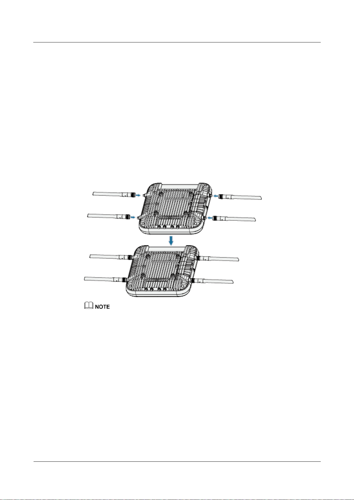
Connecting Antennas
Connect the antennas delivered in the installation accessory package of the AP to the 2.4G/5G
RF ports on the AP, tighten the nuts (with a torque of 0.8 N•m), and adjust antenna angles as
required.
Do not connect the antennas delivered in the installation accessory package of the AP to 5G antenna
interfaces. Otherwise, the AP and antennas may be damaged. The 5G antenna interfaces can be
connected only to remote antennas through feeder cables.
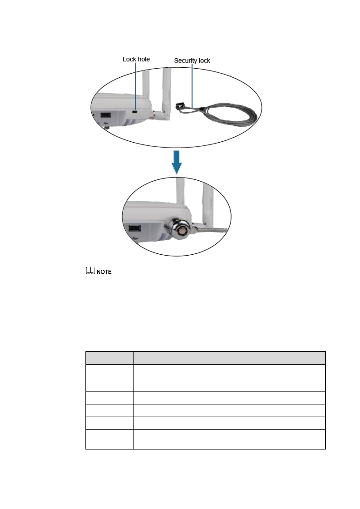
2.8 Connecting the Security Lock
There is a security slot on the device. You can lock the device to an immovable object to
prevent theft. The detailed procedures are as follows:
1. Fasten the cable of the security lock to an immovable object around.
2. Insert the security lock into the security slot and lock it.
Page 30
AP7052DN&AP7152DN
Hardware Installation and Maintenance Guide
2 AP Installation
Issue 01 (2017-12-29)
Huawei Proprietary and Confidential
Copyright © Huawei Technologies Co., Ltd.
23
No.
Check Item
1
The device is installed by strictly following the design draft. The
installation position meets space requirements, with maintenance space
reserved.
2
The device is securely installed.
3
The power cables are intact and not spliced.
4
Terminals of the power cables are welded or cramped firmly.
5
All power cables are not short-circuited or reversely connected and must
be intact with no damage.
You need to purchase the security lock separately.
2.9 Checking the Device After Installation
Table 2-6 shows the items to be checked after installation is complete. For more details, see
Installation Checklist in the appendix.
Table 2-6 Installation checklist
Page 31

AP7052DN&AP7152DN
Hardware Installation and Maintenance Guide
2 AP Installation
Issue 01 (2017-12-29)
Huawei Proprietary and Confidential
Copyright © Huawei Technologies Co., Ltd.
24
No.
Check Item
6
The power cables and ground cables are separated from other cables and
bundled separately.
7
Connectors of signal cables are complete, intact, and tightly connected.
The signal cables are not damaged or broken.
8
Labels on cables are clear and correct.
2.10 Powering on the AP
After the AP is powered on, observe the indicator on the AP to check the system running
status. For details, see 1.2 Indicator Description.
Do not frequently power on and off the device.
Page 32

AP7052DN&AP7152DN
Hardware Installation and Maintenance Guide
3 Logging In to the Device
Issue 01 (2017-12-29)
Huawei Proprietary and Confidential
Copyright © Huawei Technologies Co., Ltd.
25
About This Chapter
Parameter
Default Setting
User name
admin
Password
admin@huawei.com
3.1 Logging In to the Device Using STelnet/Telnet
3.2 Logging In to the Device Through the Web System
3.3 Logging In to the Device Through the Console Port
3 Logging In to the Device
3.1 Logging In to the Device Using STelnet/Telnet
You can log in to the device using STelnet V2 or Telnet to configure, manage, and maintain
the device in the CLI.
By default, only the STelnet V2 service is enabled on the device.
Telnet has security vulnerabilities. You are not advised to enable the Telnet service.
Device connections are classified into wired and wireless connections.
In versions earlier than V200R007C20, APs support wired connections.
In V200R007C20 and later, Fat APs support both wired and wireless connections, and
Fit APs and cloud APs support wired connections.
Before logging in to the device, complete the following tasks:
Power on the device.
Prepare network cables used to connect device interfaces for wired connections. No
network cable is required for wireless connections.
The following table lists the default configuration of the device. You are advised to change the
default user name and password on your first login.
Table 3-1 Default configuration of the device
Page 33

AP7052DN&AP7152DN
Hardware Installation and Maintenance Guide
3 Logging In to the Device
Issue 01 (2017-12-29)
Huawei Proprietary and Confidential
Copyright © Huawei Technologies Co., Ltd.
26
Parameter
Default Setting
IP address
Wired connection: 169.254.1.1
Wireless connection: 192.168.1.1
Subnet mask
Wired connection: 255.255.0.0
Wireless connection: 255.255.255.0
SSID
HUAWEI-XXXX, applicable to wireless
connections of Fat APs (XXXX specifies the
last four bits of the AP's MAC address.)
Wireless password
None, applicable to wireless connections of
Fat APs
For a Fit AP and cloud AP, you can perform the following operations:
If the Fit AP is already online on the AC, you can remotely log in to the AC on a local terminal and
run the display ap all command to check the IP address of the device.
If the Fit AP in any version is offline or the Fit AP in V200R007C10 or later does not go online, you
can access the device through the offline management VAP for operations. By default, the SSID of
the offline management VAP is hw_manage_xxxx (xxxx specifies the last four bits of the AP's MAC
address) and the password is hw_manage. After the IP address of the PC is set to 169.254.2.x/24
(169.254.2.1 excluded and 169.254.2.100 recommended), the connection is set up, you can log in to
the AP using STelnet for operations.
If the cloud AP is offline or does not go online, you can access the device through the offline
management VAP for operations. By default, the SSID of the offline management VAP is
hw_manage_xxxx (xxxx specifies the last four bits of the AP's MAC address) and the password is
hw_manage. After the PC dynamically obtains an IP address and connects to the AP, you can log in
to the AP using STelnet for operations.
The following example uses the default parameters and is used for reference only.
Wired Connection Mode
Step 1 Use a network cable to connect a PC to any network port of the AP or that of the switch on
the same network segment as the AP.
Step 2 Assign the PC with an IP address on the same network segment as the default IP address of
the device so that the PC and device are reachable to each other.
If the device uses the default settings, the IP address of the PC must be in the network
segment 169.254.0.0/16 but cannot be 169.254.1.1. 169.254.1.100 is recommended.
Step 3 Start the CLI on the PC and access the IP address 169.254.1.1 of the device using STelnet V2.
Step 4 Enter the user name and password as prompted to log in to the user interface.
----End
Wireless Connection Mode
Step 1 By default, STAs search for the WLAN HUAWEI-XXXX within the wireless signal coverage
of a Fat AP. STAs can access the WLAN without entering the password. If the SSID and
Page 34

AP7052DN&AP7152DN
Hardware Installation and Maintenance Guide
3 Logging In to the Device
Issue 01 (2017-12-29)
Huawei Proprietary and Confidential
Copyright © Huawei Technologies Co., Ltd.
27
password have been configured, use the specified SSID and password to set up a wireless
connection.
Step 2 Start the CLI on the STA and access the IP address 192.168.1.1 of the device using STelnet
V2.
Step 3 Enter the user name and password as prompted to log in to the user interface.
----End
Method of Obtaining Upgrade and Configuration Documentation
To perform subsequent upgrades and configurations after login to the device, visit Huawei
enterprise technical support website http://support.huawei.com/enterprise and search for
product documentation by keyword. The search method is described as follows:
Fit AP:
− Upgrade: Search for Fit AP upgrade guide, and refer to the upgrade guide in the
documentation of the correct version.
− Configuration: Search for AC6605 product documentation, and refer to the
configuration guide in the documentation of the correct version.
Fat AP:
− Upgrade: Search for Fat AP upgrade guide, and refer to the upgrade guide in the
documentation of the correct version.
− Configuration: Search for Fat AP product documentation, and refer to the
configuration guide in the documentation of the correct version.
cloud AP:
− Upgrade: Search for cloud AP upgrade guide, and refer to the upgrade guide in the
documentation of the correct version.
− Online configuration: Search for cloud AP product documentation, and refer to
the configuration guide in the documentation of the correct version.
− Service configuration after APs go online: Search for CloudCampus solution
product documentation, and refer to the deployment guide in the documentation
of the correct version.
3.2 Logging In to the Device Through the Web System
The built-in web system allows you to use a browser to log in to the device. You can
configure, manage, and maintain a Fat AP and cloud AP on the GUI. On the web page, you
are prompted to configure and manage a Fit AP on the AC.
Device connections are classified into wired and wireless connections.
In versions earlier than V200R007C20, APs support wired connections.
In V200R007C20 and later, Fat APs support both wired and wireless connections, and
Fit APs and cloud APs support wired connections.
Before logging in to the device, complete the following tasks:
Power on the device.
Prepare network cables used to connect device interfaces for wired connections. No
network cable is required for wireless connections.
Page 35

AP7052DN&AP7152DN
Hardware Installation and Maintenance Guide
3 Logging In to the Device
Issue 01 (2017-12-29)
Huawei Proprietary and Confidential
Copyright © Huawei Technologies Co., Ltd.
28
The following table lists the default configuration of the device. You are advised to change the
Parameter
Default Setting
User name
admin
Password
admin@huawei.com
IP address
Wired connection: 169.254.1.1
Wireless connection: 192.168.1.1
Subnet mask
Wired connection: 255.255.0.0
Wireless connection: 255.255.255.0
SSID
HUAWEI-XXXX, applicable to wireless
connections of Fat APs (XXXX specifies the
last four bits of the AP's MAC address.)
Wireless password
None, applicable to wireless connections of
Fat APs
default user name and password on your first login.
Table 3-2 Default configuration of the device
For a Fit AP and cloud AP, you can perform the following operations:
If the Fit AP in any version is offline or the Fit AP in V200R007C10 or later does not go online, you
can access the device through the offline management VAP for operations. By default, the SSID of
the offline management VAP is hw_manage_xxxx (xxxx specifies the last four bits of the AP's MAC
address) and the password is hw_manage. After the IP address of the PC is set to 169.254.2.x/24
(169.254.2.1 excluded and 169.254.2.100 recommended), the connection is set up, , and you can log
in to the AP using web system for operations.
If the cloud AP is offline or does not go online, you can access the device through the offline
management VAP for operations. By default, the SSID of the offline management VAP is
hw_manage_xxxx (xxxx specifies the last four bits of the AP's MAC address) and the password is
hw_manage. After the PC dynamically obtains an IP address and connects to the AP, you can log in
to the AP using web system for operations.
The following example uses the default parameters and is used for reference only.
Wired Connection Mode
Step 1 Use a network cable to connect a PC to any network port of the AP or that of the switch on
the same network segment as the AP.
Step 2 Assign the PC with an IP address on the same network segment as the default IP address of
the device so that the PC and device are reachable to each other.
If the device uses the default settings, the IP address of the PC must be in the network
segment 169.254.0.0/16 but cannot be 169.254.1.1. 169.254.1.100 is recommended.
Step 3 Open the browser on the PC, enter http://IP address in the address box, and press Enter to
log in. Select a language for the web system, enter the default user name and password, and
click Login to enter the web system home page.
----End
Page 36

AP7052DN&AP7152DN
Hardware Installation and Maintenance Guide
3 Logging In to the Device
Issue 01 (2017-12-29)
Huawei Proprietary and Confidential
Copyright © Huawei Technologies Co., Ltd.
29
Wireless Connection Mode
Step 1 By default, STAs search for the WLAN HUAWEI-XXXX within the wireless signal coverage
of a Fat AP. STAs can access the WLAN without entering the password. If the SSID and
password have been configured, use the specified SSID and password to set up a wireless
connection.
Step 2 Open the browser on the STA, enter http://IP address in the address box, and press Enter to
log in. Select a language for the web system, enter the default user name and password, and
click Login. The web system home page is displayed.
----End
Method of Obtaining Upgrade and Configuration Documentation
To perform subsequent upgrades and configurations after login to the device, visit Huawei
enterprise technical support website http://support.huawei.com/enterprise and search for
product documentation by keyword. The search method is described as follows:
Fit AP:
− Upgrade: Search for Fit AP upgrade guide, and refer to the upgrade guide in the
documentation of the correct version.
− Configuration: Search for AC6605 product documentation, and refer to the
configuration guide in the documentation of the correct version.
Fat AP:
− Upgrade: Search for Fat AP upgrade guide, and refer to the upgrade guide in the
documentation of the correct version.
− Configuration: Search for Fat AP product documentation, and refer to the
configuration guide in the documentation of the correct version.
cloud AP:
− Upgrade: Search for cloud AP upgrade guide, and refer to the upgrade guide in the
documentation of the correct version.
− Online configuration: Search for cloud AP product documentation, and refer to
the configuration guide in the documentation of the correct version.
− Service configuration after APs go online: Search for CloudCampus solution
product documentation, and refer to the deployment guide in the documentation
of the correct version.
3.3 Logging In to the Device Through the Console Port
Before logging in to the device, complete the following tasks:
Power on the device.
Prepare a console cable.
Prepare terminal simulation software.
If your PC's operating system provides terminal simulation software (like HyperTerminal in Windows
2000/XP), you do not need to install additional terminal simulation software. If the PC runs on an
operating system without terminal simulation software (like Windows 7), install third-party terminal
simulation software on the PC by referring to the user manual or online help.
Page 37

AP7052DN&AP7152DN
Hardware Installation and Maintenance Guide
3 Logging In to the Device
Issue 01 (2017-12-29)
Huawei Proprietary and Confidential
Copyright © Huawei Technologies Co., Ltd.
30
Step 1 Use a console cable to connect the PC to the console port of the device.
Step 2 Start terminal emulation software on the PC, create a connection, and set communication
parameters as follows:
Baud rate (B): 9600
Data bits (D): 8
Parity (P): None
Stop bits (S): 1
Flow control (F): None
Step 3 Press Enter and enter the authentication information as prompted to log in to the user view.
(The following information is only for reference.)
For a Fit AP, enter the default user name admin and password admin@huawei.com.
You are advised to change the default user name and password on your first login.
Login authentication
Username: admin
Password:
Info: You are advised to change the password to ensure security.
For a Fat AP and Cloud AP, set a passowrd of console, and use the password to log in.
Please configure the login password:
Info: A plain text password is a string of 8 to 16 case-sensitive characters and must
be a combination of at least two of the follow
ing: uppercase letters A to Z, lowercase letters a to z, digits, and special characters.
A cipher text password contains 56 or 68 ch
aracters.
Enter password:
Confirm password:
----End
Method of Obtaining Upgrade and Configuration Documentation
To perform subsequent upgrades and configurations after login to the device, visit Huawei
enterprise technical support website http://support.huawei.com/enterprise and search for
product documentation by keyword. The search method is described as follows:
Fit AP:
− Upgrade: Search for Fit AP upgrade guide, and refer to the upgrade guide in the
documentation of the correct version.
− Configuration: Search for AC6605 product documentation, and refer to the
configuration guide in the documentation of the correct version.
Fat AP:
− Upgrade: Search for Fat AP upgrade guide, and refer to the upgrade guide in the
documentation of the correct version.
− Configuration: Search for Fat AP product documentation, and refer to the
configuration guide in the documentation of the correct version.
cloud AP:
Page 38

AP7052DN&AP7152DN
Hardware Installation and Maintenance Guide
3 Logging In to the Device
Issue 01 (2017-12-29)
Huawei Proprietary and Confidential
Copyright © Huawei Technologies Co., Ltd.
31
− Upgrade: Search for cloud AP upgrade guide, and refer to the upgrade guide in the
documentation of the correct version.
− Online configuration: Search for cloud AP product documentation, and refer to
the configuration guide in the documentation of the correct version.
− Service configuration after APs go online: Search for CloudCampus solution
product documentation, and refer to the deployment guide in the documentation
of the correct version.
Page 39

AP7052DN&AP7152DN
Hardware Installation and Maintenance Guide
4 Hardware Failures
Issue 01 (2017-12-29)
Huawei Proprietary and Confidential
Copyright © Huawei Technologies Co., Ltd.
32
About This Chapter
Power Supply Mode
Possible Cause
Power supply using a power module
The device is powered off.
The power cable is not securely
connected to the device.
The power supply unit has failed.
− If the device connects to an external
power source, its power adapter may
fail.
− If the device has a built-in power
supply, the device itself may be
faulty.
PoE power supply
The power sourcing equipment does not
support the PoE function or is faulty.
The power sourcing equipment does not
support the required power supply mode.
The power sourcing equipment does not
provide sufficient power.
The power sourcing equipment is
incorrectly configured (the PoE function
This section describes common methods for troubleshooting typical hardware faults.
4.1 A Device Fails to Be Powered On
4 Hardware Failures
4.1 A Device Fails to Be Powered On
Fault Description
The indicator of a device is off.
Possible Causes
Page 40

AP7052DN&AP7152DN
Hardware Installation and Maintenance Guide
4 Hardware Failures
Issue 01 (2017-12-29)
Huawei Proprietary and Confidential
Copyright © Huawei Technologies Co., Ltd.
33
Power Supply Mode
Possible Cause
is disabled or the power-off time range is
improperly set).
The line is faulty (the network cable or
distribution frame is damaged).
The device is faulty.
Power Supply Mode
Troubleshooting Procedure
Power supply using a power module
1. Check whether the device is powered
off.
2. Check that the power cable is securely
connected to the device.
3. Check whether the power supply is
normal.
Replace the power adapter with a normal
one. If the device is powered on, the
original power adapter is faulty. Contact
technical support personnel or Huawei
agent and ask them to replace the power
adapter.
4. If the device still cannot be powered on,
the device itself is faulty. Contact
technical support personnel or Huawei
agent and ask them to replace the device.
PoE power supply
1. Check whether the power sourcing
equipment supports PoE or is faulty.
2. Check whether the power output mode
of the power sourcing equipment is
supported by the powered device.
3. Check whether the power sourcing
equipment can support the maximum
power consumption of the device.
4. Check whether the configuration on the
power sourcing equipment causes PoE
power supply errors, such as the PoE
function is disabled or the power-off
time range is incorrectly set.
5. Check whether the network cable or
distribution frame is faulty.
6. If the device still cannot be powered on,
the device itself is faulty. Contact
technical support personnel or Huawei
agent and ask them to replace the device.
Troubleshooting Procedure
Page 41

AP7052DN&AP7152DN
Hardware Installation and Maintenance Guide
4 Hardware Failures
Issue 01 (2017-12-29)
Huawei Proprietary and Confidential
Copyright © Huawei Technologies Co., Ltd.
34
The output power of an 802.3af PSE port is 15.4 W, that of an 802.3at PSE port is 30 W, and that of an
802.3bt PSE port is 60 W.
Page 42

AP7052DN&AP7152DN
Hardware Installation and Maintenance Guide
5 Appendix
Issue 01 (2017-12-29)
Huawei Proprietary and Confidential
Copyright © Huawei Technologies Co., Ltd.
35
About This Chapter
5.1 On-site Cable Assembly and Installation
5.2 Environmental Requirements for Device Operation
5.3 Equipment Grounding Specifications
5 Appendix
5.4 Engineering Labels for Cables
5.5 Guide to Using Optical Modules
5.6 Fault Tag
5.7 Installation Checklist
5.8 Guide to Making Drip Loops
5.9 Power Adaptation Solution
5.1 On-site Cable Assembly and Installation
5.1.1 Cable Assembly Precautions
Checking the Appearance of Cables
If the cable jacket or insulation is visibly dirty, clean it before assembly.
If the jacket or insulation of a cable has visible damage, irreparable scuffing, or other
defects, do not use the cable.
If the shield layer of a cable is damaged, do not use the cable.
If the cable jacket or insulation cracks after the cable is bent or twisted, discard this cable
and check whether other cables have the same problem. If other cables have the same
problem, replace these cables.
Checking the Appearance of Connectors
Do not use connectors with visible defects, damage, rust or scuffing.
Page 43

AP7052DN&AP7152DN
Hardware Installation and Maintenance Guide
5 Appendix
Issue 01 (2017-12-29)
Huawei Proprietary and Confidential
Copyright © Huawei Technologies Co., Ltd.
36
Do not use connectors if their shells or pins have exposed part or uneven plating, or their
pins are lost, broken, or bent.
Do not use connectors that have dirt on their pins or in their jacks or if there are
conductors between pins or between pins and the shell.
Precautions for Assembly
Use dedicated tools or tools delivered by Huawei and follow the methods given here
during assembly.
Hold terminals of cables instead of pulling the cables themselves when installing or
removing cable components.
Take the following precautions when cutting or stripping cables:
− Make cables slightly longer than necessary.
− Coil cables longer than 2 m (6.56 ft) after cutting. Bind and fasten the coils using
bundling ropes. The inner diameters of the coils should be larger than 20 times the
outer diameters of the cables.
− When stripping the jackets of cables, avoid damaging the shield layers (braid or
aluminum foil), insulation, core conductors, and other jackets that do not need to be
stripped.
− After assembling cables, cut all visible cross sections of jackets to ensure that the
cross sections are arranged neatly.
− Do not touch the core conductors of cables with your hands. Terminate exposed
conductors in a timely way after stripping off insulation so that the surface of the
conductors does not become oxidized.
Take the following precautions when crimping and connecting cables or connectors:
− The terminals and conductors should be connected tightly after they are crimped.
They should not be moved or turned.
− Cut all the exposed copper wires.
− Try to avoid a second crimping of sleeves.
− Keep all the conductors clean and aligned.
The connectors, cables, and tools provided by different vendors may be different. The figures in this
document are for your reference only.
5.1.2 Assembling Power Cables
5.1.2.1 Assembling a DC 2-Pin Round Connector (A)
Context
Figure 5-1 shows the components of DC 2-PIN round connector A.
Page 44

AP7052DN&AP7152DN
Hardware Installation and Maintenance Guide
5 Appendix
Issue 01 (2017-12-29)
Huawei Proprietary and Confidential
Copyright © Huawei Technologies Co., Ltd.
37
1. Enclosure
2. Shield circle
3. Clip
4. Socket
5. Nut
Procedure
Step 1 Bind a cable tie, separate the socket and nut, and install them on the cable, as shown in Figure
Figure 5-1 Components of DC 2-pin round connector A
5-2.
Figure 5-2 Installing the nut on the cable
Step 2 Strip the cable as shown in Figure 5-3.
Page 45

AP7052DN&AP7152DN
Hardware Installation and Maintenance Guide
5 Appendix
Issue 01 (2017-12-29)
Huawei Proprietary and Confidential
Copyright © Huawei Technologies Co., Ltd.
38
Figure 5-3 Stripping the cable
Step 3 Open the clip and correctly insert the core wires to the negative and positive holes, as shown
in Figure 5-4.
Figure 5-4 Inserting core wires
Step 4 Use a Phillips screwdriver to tighten the crimping screw in "+" hole, rotate the connector by
180 degree, and tighten the crimping screw in "-" hole, as shown in Figure 5-5.
Page 46

AP7052DN&AP7152DN
Hardware Installation and Maintenance Guide
5 Appendix
Issue 01 (2017-12-29)
Huawei Proprietary and Confidential
Copyright © Huawei Technologies Co., Ltd.
39
Figure 5-5 Tightening the crimping screws
Step 5 Close the clip and tighten the screw to compact the shield layer, as shown in Figure 5-6.
Figure 5-6 Compacting the shield layer
Step 6 Pre-tighten the socket and enclosure and use the Phillips screwdriver to tighten the socket
with the tightening torque no less than 1.2 N•m, as shown in Figure 5-7.
Figure 5-7 Tightening the socket
Step 7 Pre-tighten the socket and nut and use the Phillips screwdriver to tighten the nut with the
tightening torque no less than 1.2 N•m, as shown in Figure 5-8.
Page 47

AP7052DN&AP7152DN
Hardware Installation and Maintenance Guide
5 Appendix
Issue 01 (2017-12-29)
Huawei Proprietary and Confidential
Copyright © Huawei Technologies Co., Ltd.
40
Figure 5-8 Tightening the nut
Step 8 Use a multimeter to check the connectivity of the 2-pin round connector's cable components,
as shown in Figure 5-9.
Figure 5-9 Checking connectivity
The connectivity meets standards if the following conditions are met:
Positive and negative holes of the connector are not short-circuited.
The metal enclosure and connector's holes are not short-circuited.
The cable shield layer is properly connected to the metal enclosure.
Core wires are properly connected to the connector's holes.
Step 9 If devices are installed outdoor, wrap three layers of PVC insulation tape around the
connector for protection, as shown in Figure 5-10.
Ensure that proper quantity of the PVC insulation tape is used for wrapping the connector,
facilitating the connector uninstallation in later maintenance.
Page 48

AP7052DN&AP7152DN
Hardware Installation and Maintenance Guide
5 Appendix
Issue 01 (2017-12-29)
Huawei Proprietary and Confidential
Copyright © Huawei Technologies Co., Ltd.
41
Figure 5-10 Wrapping PVC insulation tape
AAU Side
Cable
Commonly-Used
Colors
Colors Used in
Britain
DC round
waterproof
connector
RTN (+)
Black or brown
Blue
NEG (-)
Blue
Gray
----End
5.1.2.2 Assembling a DC 2-Pin Round Connector (B)
This topic describes how to assemble a DC 2-pin round connector (B) and key operations.
Context
Table 5-1 lists power cables connected to the active antenna unit (AAU).
Table 5-1 AAU power cable
The color and appearance of cables in this topic are for reference only. The cable color and appearance
vary depending on countries and regions.
Figure 5-11 shows components of the DC round waterproof connector.
Page 49

AP7052DN&AP7152DN
Hardware Installation and Maintenance Guide
5 Appendix
Issue 01 (2017-12-29)
Huawei Proprietary and Confidential
Copyright © Huawei Technologies Co., Ltd.
42
1. Enclosure
2. Socket
3-1. Clamping jaw 1
3-2. Clamping jaw 2
4. Nut
Procedure
1. Clamping jaw 1
2. Clamping jaw 2
Step 1 Determine the diameter of the cable to be installed. If the diameter is larger than 14 mm,
Figure 5-11 Components of the DC round waterproof connector
replace the clamping jaw, as shown in Figure 5-12. During the replacement, connect the
clamping jaw boss to the groove inside the socket and ensure that the clamping jaw is
completely installed in the socket, as shown in Figure 5-13.
Power cables supported by clamping jaw 1: 2 x 12 AWG, 2 x 4 mm2, and 2 x 6 mm2
Power cables supported by clamping jaw 2: 2 x 8 AWG and 2 x 10 mm2
Figure 5-12 Replacing clamping jaws
Page 50

AP7052DN&AP7152DN
Hardware Installation and Maintenance Guide
5 Appendix
Issue 01 (2017-12-29)
Huawei Proprietary and Confidential
Copyright © Huawei Technologies Co., Ltd.
43
Figure 5-13 Correct operation for replacing a clamping jaw
1. Groove
2. Boss
1. Cable
2. Plastic cable tie
Step 2 Reserve the cable length at the assembly end, bind the plastic cable tie, install the nut,
clamping jaw, and socket on the cable and pre-tighten them, as shown in Figure 5-14.
Figure 5-14 Pre-tightening
Step 3 Use the stripping ruler card to measure required lengths, strip the outer jacket (48 mm) on the
head of the cable to be connected and the outer jacket (17 mm) of each core wire, twist the
shield layers into one strand, as shown in Figure 5-15.
Page 51

AP7052DN&AP7152DN
Hardware Installation and Maintenance Guide
5 Appendix
Issue 01 (2017-12-29)
Huawei Proprietary and Confidential
Copyright © Huawei Technologies Co., Ltd.
44
1. Shield layer
The stripping ruler card is delivered with the components of the connector.
Cut the padding using diagonal pliers.
Gently strip the insulation sheath to avoid damage to the conductor metal.
Ensure that the edge of core wires is not split.
Figure 5-15 Stripping the cable
Step 4 Connect the cable NEG (-) (gray in Britain and blue in other countries) to - end of the
connector and cable RTN (+) (blue in Britain and black/brown in other countries) to + end of
the connector. Tighten two crimping screws using the Phillips screwdriver and compact the
cable with tightening torque 1.4 N•m, as shown in Figure 5-16.
Figure 5-16 Tightening the crimping screws
Step 5 After the cables are assembled, pull the cables slightly to check whether the connections are
secure. If the cable slides outward or the wire of the cable is exposed outside the hole for the
Page 52

AP7052DN&AP7152DN
Hardware Installation and Maintenance Guide
5 Appendix
Issue 01 (2017-12-29)
Huawei Proprietary and Confidential
Copyright © Huawei Technologies Co., Ltd.
45
cable, remove the cable, cut the split wires, and then strip the jacket and install the cable
1. Shield layer
again.
Step 6 Twist the shield layers into one strand and insert it into the shield slot, tighten the tail screw,
and fasten the shielded layer with tightening torque 1.4 N•m, as shown in Figure 5-17.
Figure 5-17 Compacting the shield layer
Cut the extra shield layer using the diagonal pliers.
Step 7 Tighten the socket and enclosure until the red line on the socket is invisible, as shown in
Figure 5-18.
Page 53

AP7052DN&AP7152DN
Hardware Installation and Maintenance Guide
5 Appendix
Issue 01 (2017-12-29)
Huawei Proprietary and Confidential
Copyright © Huawei Technologies Co., Ltd.
46
Figure 5-18 Tightening the socket and enclosure
Step 8 Pre-tighten the nut and socket and further tighten the nut using a torque wrench (opening
width: 28 mm), as shown in Figure 5-19.
Figure 5-19 Tightening the nut
Step 9 Use a multimeter to check the reliability of cable components, as shown in Figure 5-20.
Page 54

AP7052DN&AP7152DN
Hardware Installation and Maintenance Guide
5 Appendix
Issue 01 (2017-12-29)
Huawei Proprietary and Confidential
Copyright © Huawei Technologies Co., Ltd.
47
Figure 5-20 Checking reliability
Ensure that the short circuit does not occur between the positive and negative holes of the
connector.
Ensure that the short circuit does not occur between the metal enclosure and connector's
positive and negative holes.
Step 10 If devices are installed outdoor, wrap three layers of PVC insulation tape around the
connector for protection, as shown in Figure 5-21.
Figure 5-21 Wrapping PVC insulation tape
Ensure that proper quantity of the PVC insulation tape is used for wrapping the connector,
facilitating the connector uninstallation in later maintenance.
----End
Page 55

AP7052DN&AP7152DN
Hardware Installation and Maintenance Guide
5 Appendix
Issue 01 (2017-12-29)
Huawei Proprietary and Confidential
Copyright © Huawei Technologies Co., Ltd.
48
5.1.2.3 Assembling the OT Terminal and Power Cable
A. Heat-shrinkable tubing
B. Bare crimping terminal
C. Insulation
D. Conductor
Context
Figure 5-22 shows the components of an OT terminal and a power cable.
Figure 5-22 Components of an OT terminal and a power cable
Procedure
Step 1 Based on the cross-sectional area of the cable conductor, strip a length of insulation coating C
to expose the conductor D of length L1, as shown in Figure 5-23. The recommended values of
L1 are listed in Table 5-2.
Figure 5-23 Stripping a power cable (OT terminal)
Page 56

AP7052DN&AP7152DN
Hardware Installation and Maintenance Guide
5 Appendix
Issue 01 (2017-12-29)
Huawei Proprietary and Confidential
Copyright © Huawei Technologies Co., Ltd.
49
Cross-Section
al Area of
Conductor
(mm2(in.2))
Value of L1
(mm(in.))
Cross-Sectional
Area of Conductor
(mm2(in.2))
Value of L1
(mm(in.))
1 (0.002)
7 (0.28)
10 (0.015)
11 (0.43)
1.5 (0.002)
7 (0.28)
16 (0.025)
13 (0.51)
2.5 (0.004)
7 (0.28)
25 (0.039)
14 (0.55)
4 (0.006)
8 (0.31)
35 (0.054)
16 (0.63)
6 (0.009)
9 (0.35)
50 (0.077)
16 (0.63)
When you strip a power cable, do not damage the conductor of the cable.
If the bare crimping terminal is not provided by Huawei, the value of L1 is 1 mm (0.04 in.)
to 2 mm (0.08 in.) greater than the value of L.
Table 5-2 Mapping between the cross-sectional area of the conductor and the value of L1
If you are proficient in assembling OT terminals and power cables, you can obtain the value of L1 by
comparing the part to be crimped with the power cable.
Step 2 Put the heat-shrinkable (A) tubing onto the bare crimping terminal, as shown in Figure 5-24.
Figure 5-24 Putting the heat shrink tubing onto the bare crimping terminal
Step 3 Put the OT terminal B onto the exposed conductor, and ensure that the OT terminal is in good
contact with the insulation coating C, as shown in Figure 5-24.
Page 57

AP7052DN&AP7152DN
Hardware Installation and Maintenance Guide
5 Appendix
Issue 01 (2017-12-29)
Huawei Proprietary and Confidential
Copyright © Huawei Technologies Co., Ltd.
50
After the conductor is fed into the OT terminal, the protruding part of the conductor, or L2 in
Figure 5-24, must not be longer than 2 mm (0.08 in.).
Step 4 Crimp the joint parts of the bare crimping terminal and the conductor, as shown in Figure
5-25.
The shapes of crimped parts may vary with the crimping dies.
Figure 5-25 Crimping the joint parts of the bare crimping terminal and the conductor (OT
terminal)
Step 5 Push the heat shrink tubing (A) toward the connector until the tube covers the crimped part,
and then use a heat gun to heat the tube, as shown in Figure 5-26.
Figure 5-26 Heating the heat shrink tubing (OT terminal)
Page 58

AP7052DN&AP7152DN
Hardware Installation and Maintenance Guide
5 Appendix
Issue 01 (2017-12-29)
Huawei Proprietary and Confidential
Copyright © Huawei Technologies Co., Ltd.
51
A. JG
terminal
B. Heat-shrinkable
tubing
C. Insulation layer of a
power cable
D. Conductor of a
power cable
Stop heating the shrink tubing when the connector is securely locked in the shrink tubing. Do
not heat the shrink tubing too long as this may damage the insulation coating.
----End
5.1.2.4 Assembling the JG Terminal and Power Cable
Context
Figure 5-27 shows the components of a JG terminal and a power cable.
Figure 5-27 Components of a JG terminal and a power cable
Procedure
Step 1 Strip a part of the insulation to expose the cable conductor with a length of L, as shown in
Figure 5-28. The recommended values of L are listed in Table 5-3.
Page 59

AP7052DN&AP7152DN
Hardware Installation and Maintenance Guide
5 Appendix
Issue 01 (2017-12-29)
Huawei Proprietary and Confidential
Copyright © Huawei Technologies Co., Ltd.
52
Cross-Sectional Area of Conductor
(mm2(in.2))
Value of L (mm(in.))
16 (0.025)
13 (0.51)
25 (0.039)
14 (0.55)
35 (0.054)
16 (0.63)
50 (0.077)
16 (0.63)
When you strip a power cable, do not damage the conductor of the cable.
If the bare crimping terminal is not provided by Huawei, you can adjust the value of L as
required.
Figure 5-28 Stripping a power cable (JG terminal)
Table 5-3 Mapping between the cross-sectional area of the conductor and the value of L
Step 2 Put the heat shrink tubing onto the bare crimping terminal, as shown in Figure 5-29.
Figure 5-29 Putting the heat shrink tubing onto the bare crimping terminal
Page 60

AP7052DN&AP7152DN
Hardware Installation and Maintenance Guide
5 Appendix
Issue 01 (2017-12-29)
Huawei Proprietary and Confidential
Copyright © Huawei Technologies Co., Ltd.
53
Step 3 Put the bare crimping terminal onto the exposed conductor, and ensure that the bare crimping
terminal is in good contact with the insulation of the power cable, as shown in Figure 5-29.
Step 4 Crimp the joint parts of the bare crimping terminal and the conductor, as shown in Figure
5-30.
Figure 5-30 Crimping the joint parts of the bare crimping terminal and the conductor (JG
terminal)
Step 5 Push the heat shrink tubing toward the connector until the tube covers the crimped part, and
then use a heat gun to heat the tube, as shown in Figure 5-31.
Figure 5-31 Heating the heat shrink tubing (JG terminal)
----End
5.1.2.5 Assembling the Cord End Terminal and the Power Cable
Context
Figure 5-32 shows the components of a cord end terminal and a power cable.
Page 61

AP7052DN&AP7152DN
Hardware Installation and Maintenance Guide
5 Appendix
Issue 01 (2017-12-29)
Huawei Proprietary and Confidential
Copyright © Huawei Technologies Co., Ltd.
54
A. Cord end
terminal
B. Insulation layer of a power
cable
C. Conductor of a power
cable
Procedure
Cross-Section
al Area of
Conductor
(mm2(in.2))
Value of L1
(mm(in.))
Cross-Sectional
Area of Conductor
(mm2(in.2))
Value of L1
(mm(in.))
Step 1 Strip a part of the insulation to expose the cable conductor with a length of L1, as shown in
Figure 5-32 Components of a cord end terminal and a power cable
Figure 5-33. The recommended values of L1 are listed in Table 5-4.
When you strip a power cable, do not damage the conductor of the cable.
Figure 5-33 Stripping a power cable (cord end terminal)
Table 5-4 Mapping between the cross-sectional area of the conductor and the value of L1
Page 62

AP7052DN&AP7152DN
Hardware Installation and Maintenance Guide
5 Appendix
Issue 01 (2017-12-29)
Huawei Proprietary and Confidential
Copyright © Huawei Technologies Co., Ltd.
55
Cross-Section
al Area of
Conductor
(mm2(in.2))
Value of L1
(mm(in.))
Cross-Sectional
Area of Conductor
(mm2(in.2))
Value of L1
(mm(in.))
1 (0.002)
8 (0.31)
10 (0.015)
15 (0.59)
1.5 (0.002)
10 (0.39)
16 (0.025)
15 (0.59)
2.5 (0.004)
10 (0.39)
25 (0.039)
18 (0.71)
4 (0.006)
12 (0.47)
35 (0.054)
19 (0.75)
6 (0.009)
14 (0.55)
50 (0.077)
26 (1.02)
Step 2 Put the cord end terminal onto the conductor, and ensure that the conductor is aligned with the
edge of the cord end terminal, as shown in Figure 5-34.
After the conductor is fed into the cord end terminal, the protruding part of the conductor
must not be longer than 1 mm (0.04 in.).
Figure 5-34 Putting the cord end terminal onto the conductor
Step 3 Crimp the joint parts of the cord end terminal and the conductor, as shown in Figure 5-35.
Page 63

AP7052DN&AP7152DN
Hardware Installation and Maintenance Guide
5 Appendix
Issue 01 (2017-12-29)
Huawei Proprietary and Confidential
Copyright © Huawei Technologies Co., Ltd.
56
Figure 5-35 Crimping the cord end terminal and the conductor
Cross-Sectional Area of Tubular
Terminal (mm2(in.2))
Maximum Width of Crimped Terminal
W1 (mm(in.))
0.25 (0.0004)
1 (0.04)
0.5 (0.0008)
1 (0.04)
1.0 (0.0015)
1.5 (0.06)
1.5 (0.0023)
1.5 (0.06)
2.5 (0.0039)
2.4 (0.09)
4 (0.006)
3.1 (0.12)
6 (0.009)
4 (0.16)
10 (0.015)
5.3 (0.21)
16 (0.025)
6 (0.24)
25 (0.039)
8.7 (0.34)
35 (0.054)
10 (0.39)
Step 4 Check the maximum width of the tubular crimped terminal. The maximum width of a tubular
crimped terminal is listed in Table 5-5.
Table 5-5 Maximum width of a tubular crimped terminal
----End
Page 64

AP7052DN&AP7152DN
Hardware Installation and Maintenance Guide
5 Appendix
Issue 01 (2017-12-29)
Huawei Proprietary and Confidential
Copyright © Huawei Technologies Co., Ltd.
57
5.1.3 Assembling Ethernet Cables
A. Jacket of
connector
B. Metal shell of
connector
C. Wire holder of
connector
D. Plug of
connector
E. Jacket of
Ethernet cable
F. Shield layer of
Ethernet cable
G. Twisted-pair wires
-
5.1.3.1 Assembling the Shielded RJ45 Connector and Ethernet Cable
Context
Figure 5-36 shows the components of an RJ45 connector and a shielded Ethernet cable.
Figure 5-36 Shielded RJ45 connector and cable
Procedure
Step 1 Fit the jacket of the connector onto the Ethernet cable, as shown in Figure 5-37.
Figure 5-37 Fitting the jacket of the connector onto the Ethernet cable
Page 65

AP7052DN&AP7152DN
Hardware Installation and Maintenance Guide
5 Appendix
Issue 01 (2017-12-29)
Huawei Proprietary and Confidential
Copyright © Huawei Technologies Co., Ltd.
58
Step 2 Remove a 30 mm (1.18 in.) long section of the jacket, cut off the nylon twine inside the jacket,
and cut a no more than 5 mm (0.20 in.) cleft in the jacket, as shown in Figure 5-38.
When you remove a section of the jacket, do not damage the shield layer of the
twisted-pair cable.
When you remove the shield layer, do not damage the insulation of the twisted-pair cable.
Figure 5-38 Removing the jacket of a twisted-pair cable (unit: mm (in.))
Step 3 Fit the metal shell onto the twisted-pair cable. The shield layer is covered by the metal shell,
as shown in Figure 5-39.
Figure 5-39 Fitting the metal shell onto the twisted-pair cable
Step 4 Fit the metal shell onto the twisted-pair cable until the shield layer is covered completely.
Along the edge of the metal shell, cut off the aluminum foil shield layer and ensure that there
is no surplus copper wire. The exposed twisted-pair cable is about 20 mm (0.79 in.) long, as
shown in Figure 5-40.
Page 66

AP7052DN&AP7152DN
Hardware Installation and Maintenance Guide
5 Appendix
Issue 01 (2017-12-29)
Huawei Proprietary and Confidential
Copyright © Huawei Technologies Co., Ltd.
59
Figure 5-40 Removing the shield layer of a twisted-pair cable (unit: mm (in.))
C
G
White-Green
Green
White-Orange
Orange
Blue
White-Blue
White-Brown
Brown
Step 5 Lead the four pairs of twisted-pair wires through the wire holder, as shown in Figure 5-41 and
Figure 5-42. Ensure that the colored wires are in the correct location in the cable.
Figure 5-41 Leading wires through the wire holder
Figure 5-42 Cable locations in a wire holder
Step 6 Align the four pairs of cables in the holder, as shown in Figure 5-43. The connections
between the wires and the pins are shown in Figure 5-44 and listed in Table 5-6.
Page 67

AP7052DN&AP7152DN
Hardware Installation and Maintenance Guide
5 Appendix
Issue 01 (2017-12-29)
Huawei Proprietary and Confidential
Copyright © Huawei Technologies Co., Ltd.
60
Figure 5-43 Four pairs of cables on a wire holder
Brown
White-Brown
Green
White-Blue
Blue
White-Green
Orange
White-Orange
Pin 8
Pin 1
Matching Pins of Wires
Wire Color
1
White-Orange
2
Orange
3
White-Green
4
Blue
5
White-Blue
6
Green
7
White-Brown
8
Brown
Figure 5-44 Connections between wires and pins
Table 5-6 Connections between wires and pins (using a straight-through cable as an example)
Page 68

AP7052DN&AP7152DN
Hardware Installation and Maintenance Guide
5 Appendix
Issue 01 (2017-12-29)
Huawei Proprietary and Confidential
Copyright © Huawei Technologies Co., Ltd.
61
Step 7 Cut off the surplus cables along the lower edge of the wire holder, as shown in Figure 5-45.
Figure 5-45 Cutting off surplus cables
Step 8 Put the connector body onto the wire holder and turn the metal shell by 90°, as shown in
Figure 5-46.
Ensure that the wire holder is in good contact with the connector body.
Figure 5-46 Putting the connector body onto the wire holder
Step 9 Push the metal shell toward the connector body until the wire holder and the connector body
are engaged completely. Crimp the connector, as shown in Figure 5-47.
Page 69

AP7052DN&AP7152DN
Hardware Installation and Maintenance Guide
5 Appendix
Issue 01 (2017-12-29)
Huawei Proprietary and Confidential
Copyright © Huawei Technologies Co., Ltd.
62
Figure 5-47 Crimping the connector
Step 10 Push the jacket towards the metal shell until the metal shell is covered. This completes the
assembly of one end of the cable, as shown in Figure 5-48.
Figure 5-48 Pushing the metal shell
Step 11 To complete the assembly of the other end, repeat steps 1 to 10.
----End
5.1.3.2 Assembling an Optimized Shielded RJ45 Connector and SFTP
Network Cables
Context
This topic describes how to assemble an optimized shielded RJ45 connector with a Secure
File Transfer Protocol (SFTP) straight-through network cable as an example. The connector
has a cable support rack but does not have a metal jacket. Such a connector can be used for
crimping CAT. 6 network cables.
Figure 5-49 shows the shielded RJ45 connector.
Page 70

AP7052DN&AP7152DN
Hardware Installation and Maintenance Guide
5 Appendix
Issue 01 (2017-12-29)
Huawei Proprietary and Confidential
Copyright © Huawei Technologies Co., Ltd.
63
Figure 5-49 Shielded RJ45 connector
1: Core
wires
2: Aluminum
foil
3: Braid
shield
4: Outer
jacket
5: RJ45
connector
6: Load
bar
7: Cable
support rack
Procedure
Step 1 Strip 20 mm outer jacket off the network cable, peel off the braid shield backward, and cut off
the aluminum foil and protection band, as shown in Figure 5-50.
Ensure that the shielded layer is intact when stripping outer jackets off the network cable.
Keep the cable insulation intact when stripping the shielded layer.
Page 71

AP7052DN&AP7152DN
Hardware Installation and Maintenance Guide
5 Appendix
Issue 01 (2017-12-29)
Huawei Proprietary and Confidential
Copyright © Huawei Technologies Co., Ltd.
64
Figure 5-50 Stripping the cable
Step 2 Arrange core wires in the order of colors shown in Figure 5-51 and fix the cable support rack
to the bottom of the core wires.
Figure 5-51 Core wire order
Step 3 Hold the arranged core wires and route them through the load bar, as shown in Figure 5-52.
Table 5-7 shows the mapping between the core wires and pins of the connector.
Page 72

AP7052DN&AP7152DN
Hardware Installation and Maintenance Guide
5 Appendix
Issue 01 (2017-12-29)
Huawei Proprietary and Confidential
Copyright © Huawei Technologies Co., Ltd.
65
Figure 5-52 Routing the core wires through the load bar
Pin ID
Core Wire Color
1
White-orange
2
Orange
3
White-green
4
Blue
5
White-blue
6
Green
7
White-brown
8
Brown
Table 5-7 Mapping between core wires and pins
Step 4 After routing core wires through the load bar, move the load bar to the bottom to connect to
the cable support rack, and neatly cut the edge cables, as shown in Figure 5-53.
Page 73

AP7052DN&AP7152DN
Hardware Installation and Maintenance Guide
5 Appendix
Issue 01 (2017-12-29)
Huawei Proprietary and Confidential
Copyright © Huawei Technologies Co., Ltd.
66
Figure 5-53 Neatly cutting edge cables
Step 5 Insert the load bar into the RJ45 connector, as shown in Figure 5-54.
Figure 5-54 Inserting the load bar into the RJ45 connector
Cables must be inserted into the bottom of the connector, which can be checked on the side or
front end face of the connector.
Step 6 Use the crimping tool to crimp the connector, as shown in Figure 5-55. Use cutting pliers to
neatly cut braid shields exposed out of the connector along the load bar, as shown in Figure
5-56.
Figure 5-55 Crimping the connector
Page 74

AP7052DN&AP7152DN
Hardware Installation and Maintenance Guide
5 Appendix
Issue 01 (2017-12-29)
Huawei Proprietary and Confidential
Copyright © Huawei Technologies Co., Ltd.
67
Figure 5-56 Neatly cutting braid shields
Step 7 Repeat Step 1 through Step 6 to assemble the optimized shielded RJ45 connector on the other
end of the network cable.
----End
5.1.3.3 Assembling an Integrated Shielded RJ45 Connector and SFTP
Network Cables
Context
This topic describes how to assemble an integrated shielded RJ45 connector with a Secure
File Transfer Protocol (SFTP) straight-through network cable as an example. The connector
does not have a cable support rack or metal jacket.
Figure 5-57 shows the integrated shielded RJ45 connector.
Page 75

AP7052DN&AP7152DN
Hardware Installation and Maintenance Guide
5 Appendix
Issue 01 (2017-12-29)
Huawei Proprietary and Confidential
Copyright © Huawei Technologies Co., Ltd.
68
Figure 5-57 Shielded RJ45 connector
1: Core wires
2: Aluminum foil
3: Braid shield
4: Outer jacket
5: RJ45 connector
Procedure
Step 1 Strip 20 mm outer jacket off the network cable, peel off the braid shield backward, and cut off
the aluminum foil and protection band, as shown in Figure 5-58.
Ensure that the shielded layer is intact when stripping outer jackets off the network cable.
Keep the cable insulation intact when stripping the shielded layer.
Page 76

AP7052DN&AP7152DN
Hardware Installation and Maintenance Guide
5 Appendix
Issue 01 (2017-12-29)
Huawei Proprietary and Confidential
Copyright © Huawei Technologies Co., Ltd.
69
Figure 5-58 Stripping the cable
Pin ID
Core Wire Color
1
White-orange
2
Orange
3
White-green
4
Blue
5
White-blue
Step 2 Arrange the twisted pair wires in the order of colors shown in Table 5-8 and cut the wire ends
neatly with 12 mm core wires left, as shown in Figure 5-59.
Figure 5-59 Core wire order
Table 5-8 Mapping between core wires and pins
Page 77

AP7052DN&AP7152DN
Hardware Installation and Maintenance Guide
5 Appendix
Issue 01 (2017-12-29)
Huawei Proprietary and Confidential
Copyright © Huawei Technologies Co., Ltd.
70
Pin ID
Core Wire Color
6
Green
7
White-brown
8
Brown
Step 3 Route the arranged core wires through the RJ45 connector, as shown in Figure 5-60.
Figure 5-60 Routing core wires through the connector
Step 4 Use the crimping tool to crimp the connector, as shown in Figure 5-61.
Figure 5-61 Crimping the connector
Step 5 Neatly cut braid shields exposed out of the connector along the load bar, as shown in Figure
5-62.
Page 78

AP7052DN&AP7152DN
Hardware Installation and Maintenance Guide
5 Appendix
Issue 01 (2017-12-29)
Huawei Proprietary and Confidential
Copyright © Huawei Technologies Co., Ltd.
71
Figure 5-62 Neatly cutting braid shields
Step 6 Repeat Step 1 through Step 5 to assemble the integrated shielded RJ45 connector on the other
end of the network cable.
----End
5.1.3.4 Assembling a Shielded RJ45 Connector and an FTP Network Cable
Context
This topic describes how to assemble a shielded RJ45 connector and File Transfer Protocol
(FTP) network cable and related notes.
Figure 5-64 shows the shielded RJ45 connector.
Figure 5-63 Connector jacket
Figure 5-64 Shielded RJ45 connector
Page 79

AP7052DN&AP7152DN
Hardware Installation and Maintenance Guide
5 Appendix
Issue 01 (2017-12-29)
Huawei Proprietary and Confidential
Copyright © Huawei Technologies Co., Ltd.
72
A: Connector
jacket
B:
Connector
C: Core wires
of the twisted
pair
D: Aluminum foil used
as the network cable
shield
E: Network
cable jacket
Procedure
Step 1 Route the network cable through the connector jacket, as shown in Figure 5-66.
Figure 5-65 Cable
Figure 5-66 Routing the network cable through the connector jacket
Step 2 Strip 20 mm outer jacket off the cable and cut off the nylon layer inside the jacket, as shown
in Figure 5-67.
Ensure that the aluminum foil used as a shielded layer is intact when stripping outer jackets
off the twisted pair cable.
Page 80

AP7052DN&AP7152DN
Hardware Installation and Maintenance Guide
5 Appendix
Issue 01 (2017-12-29)
Huawei Proprietary and Confidential
Copyright © Huawei Technologies Co., Ltd.
73
Figure 5-67 Stripping the outer jacket
Step 3 Pull outward the shielded aluminum foil and cut off the PET membrane and ground cables
along the end face of the outer jacket, as shown in Figure 5-68.
Figure 5-68 Cutting off the PET membrane and ground cables
Step 4 Arrange the twisted core wires according to color order shown in Figure 5-69. Use cutting
pliers to neatly cut the front end of the twisted pair, as shown in Figure 5-70. Figure 5-71
shows pin arrangement of each contact of the connector.
Page 81

AP7052DN&AP7152DN
Hardware Installation and Maintenance Guide
5 Appendix
Issue 01 (2017-12-29)
Huawei Proprietary and Confidential
Copyright © Huawei Technologies Co., Ltd.
74
Figure 5-69 Mapping between colors and pins
Pin8
Pin1
Figure 5-70 Neatly cutting the twisted pair
Figure 5-71 Pin arrangement of the connector
Step 5 Insert the arranged four twisted pair cables into the connector, as shown in Figure 5-72.
Page 82

AP7052DN&AP7152DN
Hardware Installation and Maintenance Guide
5 Appendix
Issue 01 (2017-12-29)
Huawei Proprietary and Confidential
Copyright © Huawei Technologies Co., Ltd.
75
Cables must be inserted into the bottom.
The aluminum foil must keep intact after cables are inserted into the connector.
Figure 5-72 Inserting cables into the connector
Step 6 Use the crimping tool dedicated for FTP network cables to crimp the connector and neatly cut
the aluminum foil along the end face of the connector, as shown in Figure 5-73.
Figure 5-73 Crimping the connector
Page 83

AP7052DN&AP7152DN
Hardware Installation and Maintenance Guide
5 Appendix
Issue 01 (2017-12-29)
Huawei Proprietary and Confidential
Copyright © Huawei Technologies Co., Ltd.
76
Step 7 Move the connector jacket to the connector body to wrap the connector shell, as shown in
A
B
C
A. Plug of connector
B. Jacket
C. Twisted-pair wires
Figure 5-74.
Figure 5-74 Wrapping the connector shell
Step 8 Repeat Step 1 through Step 7 to assemble the shielded RJ45 connector on the other end of the
network cable.
----End
5.1.3.5 Assembling an Unshielded RJ45 Connector and Ethernet Cable
Context
Figure 5-75 shows the components of an unshielded RJ45 connector and cable.
Figure 5-75 Components of an unshielded RJ45 connector and cable
Page 84

AP7052DN&AP7152DN
Hardware Installation and Maintenance Guide
5 Appendix
Issue 01 (2017-12-29)
Huawei Proprietary and Confidential
Copyright © Huawei Technologies Co., Ltd.
77
Procedure
C
16
White-Orange
White-Green
Orange
Blue
White-Blue
Green
White-Brown
Brown
Pin 8
Pin 1
Matching Pins of Wires
Wire Color
1
White-Orange
2
Orange
3
White-Green
4
Blue
5
White-Blue
6
Green
7
White-Brown
Step 1 Remove a 16-mm (0.63 in.) long section of the jacket, as shown in Figure 5-76.
When you remove the shield layer, do not damage the insulation of the twisted-pair cable.
Figure 5-76 Removing the jacket of a twisted-pair cable (unit: mm (in.))
Step 2 Align the four pairs of wires and cut the ends neatly, as shown in Figure 5-77. The
connections between the wires and the pins are listed in Table 5-9.
Figure 5-77 Connections between wires and pins (unit: mm (in.))
Table 5-9 Connections between wires and pins (using a straight-through cable as an example)
Page 85

AP7052DN&AP7152DN
Hardware Installation and Maintenance Guide
5 Appendix
Issue 01 (2017-12-29)
Huawei Proprietary and Confidential
Copyright © Huawei Technologies Co., Ltd.
78
Matching Pins of Wires
Wire Color
8
Brown
Step 3 Feed the cable into the plug, and crimp the connector, as shown in Figure 5-78.
When inserting the cable, check from the side or bore of the plug to ensure that the cable is completely
seated in the plug.
Figure 5-78 Crimping the connector
Step 4 To complete the assembly of the other end, repeat steps 1 to 3.
----End
5.1.3.6 Checking the Appearance of Contact Strips
Context
To ensure proper contact between the crimped wires and the wire conductors, the heights
and sizes of the contact strips must be standard and the same.
The contact strips must be parallel to each other, with an offset of less than ± 5°. The top
margin of a strip must be parallel to the axis of the connector, with an offset of less than
± 10°.
To ensure conductivity, the surface of the contact strips must be clean.
The contact strips must be in good contact with the RJ45 socket. The plastic separators
must remain intact and be aligned.
The contact strip blade must extend beyond the ends of the wires. The ends of the wires
must be in contact with the edge of the RJ45. The distance between them must be less
than 0.5 mm (0.02 in.).
Procedure
Step 1 Hold the crimped connector, with the front side facing you, and check whether the contact
strips are of the same height. The height should be 6.02 ± 0.13 mm (0.237 ± 0.005). If a
measuring tool is not available, you can compare the connector with a standard connector.
Figure 5-79 shows an unqualified piece, and Figure 5-80 shows a qualified piece.
Page 86

AP7052DN&AP7152DN
Hardware Installation and Maintenance Guide
5 Appendix
Issue 01 (2017-12-29)
Huawei Proprietary and Confidential
Copyright © Huawei Technologies Co., Ltd.
79
All unqualified pieces must be crimped again.
Figure 5-79 Contact strips of different heights
Figure 5-80 Contact strips of the same height
Step 2 Hold an RJ45 connector and turn it 45°. Observe the top edges of the metal contact strips.
Figure 5-81 shows an unqualified piece.
Figure 5-81 Unparallel contact strips of different heights
Step 3 Check whether the contact strips are clean. If they are not clean and the dirt cannot be
removed, replace it with a new RJ45 connector. Figure 5-82 shows an unqualified piece.
Page 87

AP7052DN&AP7152DN
Hardware Installation and Maintenance Guide
5 Appendix
Issue 01 (2017-12-29)
Huawei Proprietary and Confidential
Copyright © Huawei Technologies Co., Ltd.
80
Figure 5-82 Dirt on a contract strip
Step 4 Check whether the contact strips and the plastic separators are well aligned and intact. If a
separator is skewed and cannot be fixed, replace it with a new RJ45 connector. Figure 5-83
shows an unqualified piece.
Figure 5-83 Skewed plastic separators
Step 5 Hold the connector with the side facing towards you, and check whether you can see the
cross-sections of the wires. Ensure that the ends of the wires are in good contact with the edge
of the RJ45, and that the contact strip blade extends beyond the ends of the wires and is
crimped with the wires. If not, replace the connector. Figure 5-84 shows an unqualified piece.
Figure 5-84 Wires not in good contact with the edge of the RJ45
----End
Page 88

AP7052DN&AP7152DN
Hardware Installation and Maintenance Guide
5 Appendix
Issue 01 (2017-12-29)
Huawei Proprietary and Confidential
Copyright © Huawei Technologies Co., Ltd.
81
5.1.3.7 Testing the Connection of Assembled Cables
RJ45 Connector 1
RJ45 Connector 2
Core Wire Color
Twisted or Not
2 2 Orange
Twisted
1 1 Orange-White
6 6 Green
Twisted
3 3 Green-White
4 4 Blue
Twisted
5 5 Blue-White
8 8 Brown
Twisted
7 7 Brown-White
RJ45 Connector 1
RJ45 Connector 2
Core Wire Color
Twisted or Not
6 2 Orange
Twisted
3 1 Orange-White
2 6 Green
Twisted
1 3 Green-White
4 4 Blue
Twisted
5 5 Blue-White
8 8 Brown
Twisted
7 7 Brown-White
Context
Huawei provides two types of Ethernet cables: straight-through cables and crossover cables.
Straight-through cables are connected in a one-to-one manner. They are used to connect
terminals such as a computer or switch to network devices. Table 5-10 lists the
connections of core wires in a straight-through cable.
Table 5-10 Connections of core wires in a straight-through cable
Crossover cables are connected in a crossover manner. They are used to connect
terminals such as two computers or switches. Table 5-11 lists the connections of core
wires in a crossover cable.
Table 5-11 Connections of core wires in a straight crossover cable
Figure 5-85 shows the pins of an RJ45 connector.
Page 89

AP7052DN&AP7152DN
Hardware Installation and Maintenance Guide
5 Appendix
Issue 01 (2017-12-29)
Huawei Proprietary and Confidential
Copyright © Huawei Technologies Co., Ltd.
82
Pin8
Pin1
Procedure
Step 1 Feed both connectors of the cable into the ports of the cable tester.
Step 2 After the connectors are properly inserted, turn on the tester. If the indicators from 1 to G turn
Figure 5-85 Pins of an RJ45 connector
on simultaneously, you can infer that the pins work normally and the wires are correctly
connected.
Turn the switch to the S position to slow down lighting of the indicators so that you can see the
indicators more clearly, as shown in Figure 5-86.
Figure 5-86 Testing the conduction and connections of wires
Step 3 Gently shake the connector and repeat Step 2 to check whether the metal contact strips are in
good contact with the core wires and Ethernet ports, as shown in Figure 5-87.
Page 90

AP7052DN&AP7152DN
Hardware Installation and Maintenance Guide
5 Appendix
Issue 01 (2017-12-29)
Huawei Proprietary and Confidential
Copyright © Huawei Technologies Co., Ltd.
83
Figure 5-87 Checking the reliability
The procedure for testing a crossover cable is the same as that for testing a straight-through
cable except for the sequence in which the indicators turn on, which depends on the wire
connections of a crossover cable.
The Ethernet cable is qualified if the indicators turn on in the following sequence:
At the master (left) section of the tester, the indicators turn on in the sequence of 1-8-G. At the
slave (right) section of the tester, the indicators turn on in the sequence of 3-6-1-4-5-2-7-8-G.
If the indicators do not come on in this sequence, the Ethernet cable is unqualified.
If a tester is not available, you can use a multimeter to perform a simple test, as shown in Figure 5-88.
Figure 5-88 Testing the connection of an Ethernet cable
Page 91

AP7052DN&AP7152DN
Hardware Installation and Maintenance Guide
5 Appendix
Issue 01 (2017-12-29)
Huawei Proprietary and Confidential
Copyright © Huawei Technologies Co., Ltd.
84
----End
Symptom
Cause
Preventive Measure
The device cannot be
powered using PoE.
The device restarts
frequently.
A large number of error
packets exist on the
device or services are
interrupted.
A network cable has high
resistance or is too long.
Before using network cables
purchased from other
suppliers, use a multimeter
or other tools to measure
cable resistance. If the
resistance of a network
cable does not comply with
the quality requirement of
the PoE standard, as shown
in Table 5-13, replace the
network cable.
Non-standard network cable
connectors cause poor
contact with device
interfaces.
Before making a network
cable, use a standard go-no
go gauge to test the
connectors purchased from
other suppliers. Replace the
connectors if they do not
comply with the standard.
Wires in a network cable are
connected to wrong pins.
After a network cable is
made, use a conduction
tester to measure cable
connectivity. For test
details, see 5.1.3.7 Testing
the Connection of
Assembled Cables.
A network cable connector
is not crimped securely,
causing poor contact
between the network cable
and pins in the connector.
When testing a network
cable with a conduction
tester, gently shake the cable
connector and check
whether indicators on the
conduction tester are in
normal state. If indicators 1
to G turn on in a wrong
sequence, remake the
network cable.
5.1.3.8 Common Network Cable Faults and Preventive Measures
Table 5-12 lists common network cable faults and preventive measures.
Table 5-12 Common network cable faults and preventive measures
The following methods are often used to test network cable resistance, and the test criteria are
listed in Table 5-13:
Use a network cable tester (high-end cable tester of Fluke) to measure network cable
resistance.
Page 92

AP7052DN&AP7152DN
Hardware Installation and Maintenance Guide
5 Appendix
Issue 01 (2017-12-29)
Huawei Proprietary and Confidential
Copyright © Huawei Technologies Co., Ltd.
85
Standard
Total
Resistance of
a Network
Cable
802.3af
≤ 20 ohms
802.3at
Maximum PD power consumption <
12.95 W
≤ 20 ohms
Maximum PD power consumption <
25.5 W
≤ 12.5 ohms
A. Body of
connector
B. Back shell of
connector
C. O-ring seal
D. Heat-shrink tubing
E. Cable jacket
F. Outer conductor of
feeder cable
G. Inner conductor of
feeder cable
H. Insulation layer of
feeder cable
Connect multimeter probes to two ends of each wire in a network cable and check the
resistance value on the multimeter.
Connect a network cable to an AP. Use a multimeter to test the resistance between pins 1
and 2 (or between pins 3 and 6, 4 and 5, or 7 and 8) on the other end of the cable. The
cable's DC resistance approximately equals a half of the displayed value.
Table 5-13 PoE standard requirements for network cable quality
If an AP is connected to a switch or AC (excluding ACU2), you can run the virtual-cable-test
command on the switch or AC to check network cable connectivity. For details, see the
virtual-cable-test command in the command reference.
5.1.4 Assembling Feeders
5.1.4.1 Assembling the Straight Male Coaxial N Connector and the 1/2''
Feeder
Context
Figure 5-89 shows the components of an N coaxial connector and a 1/2" feeder cable.
Figure 5-89 Components of an N coaxial connector and a 1/2" feeder cable
Page 93

AP7052DN&AP7152DN
Hardware Installation and Maintenance Guide
5 Appendix
Issue 01 (2017-12-29)
Huawei Proprietary and Confidential
Copyright © Huawei Technologies Co., Ltd.
86
Procedure
Step 1 Cut the feeder cable, as shown in Figure 5-90.
Figure 5-90 Cutting a feeder cable (unit: mm)
Ensure that the feeder cable is cut with reference to the guide in the package box of the
connector.
After you cut the feeder cable, ensure that the cross-section of the outer conductor is
smooth, intact, and round.
Ensure that the feeder cable is cut at the wave crest of the outer conductor.
The inner conductor must be beveled, as shown in Figure 5-90.
Step 2 Use a brush to remove the dirt on the cross-section of the feeder cable.
Step 3 Feed the feeder cable into the heat-shrink tubing, and cover the outer conductor of the feeder
cable with the O-ring seal, as shown in Figure 5-91.
Page 94

AP7052DN&AP7152DN
Hardware Installation and Maintenance Guide
5 Appendix
Issue 01 (2017-12-29)
Huawei Proprietary and Confidential
Copyright © Huawei Technologies Co., Ltd.
87
Figure 5-91 Installing the heat-shrink tubing and the O-ring seal
Step 4 Put the back shell of the connector onto the feeder cable. Tighten the back shell to the end of
the feeder cable, as shown in Figure 5-92.
Figure 5-92 Putting the back shell of the connector onto the feeder cable
Step 5 Mount the body of the connector onto the feeder cable so that the inner conductors of the
connector and feeder cable are connected. Use a spanner (27 N•m to 30 N•m torque
recommended) to fasten the body and back shell, as shown in Figure 5-93.
Figure 5-93 Fastening the body and back shell
Step 6 Push the heat-shrink tubing towards the connector, as shown in Figure 5-94. Then, heat the
tube.
Page 95

AP7052DN&AP7152DN
Hardware Installation and Maintenance Guide
5 Appendix
Issue 01 (2017-12-29)
Huawei Proprietary and Confidential
Copyright © Huawei Technologies Co., Ltd.
88
Figure 5-94 Assembled N connector
Step 7 After the components are assembled, install the connector, as shown in Figure 5-95.
Figure 5-95 Installing the connector
----End
5.1.4.2 Assembling a Straight Male Coaxial N Connector and an RG8U
Feeder
Context
Figure 5-96 shows the coaxial N connector and RG8U feeder.
Page 96

AP7052DN&AP7152DN
Hardware Installation and Maintenance Guide
5 Appendix
Issue 01 (2017-12-29)
Huawei Proprietary and Confidential
Copyright © Huawei Technologies Co., Ltd.
89
Figure 5-96 Coaxial N connector and RG8U feeder
A: Connector body
B: Lining
C: Clip
D: Nut
E: Cable jacket
F: Shielded layer
of the feeder
G: Aluminum foil of
the feeder
H: Insulation medium
of the feeder
I: Internal conductor
of the feeder
- - -
Procedure
Step 1 Strip the feeder with the length shown in Figure 5-97.
Ensure that the shielded layer F is intact after the stripping.
Page 97

AP7052DN&AP7152DN
Hardware Installation and Maintenance Guide
5 Appendix
Issue 01 (2017-12-29)
Huawei Proprietary and Confidential
Copyright © Huawei Technologies Co., Ltd.
90
Figure 5-97 Stripping the feeder
Step 2 Route the Cable jacket (E) through the nut (D), as shown in Figure 5-98.
Figure 5-98 Installing the nut
Step 3 Install the clip (C) on the Cable jacket (E) and move the clip until the clip is close to the Cable
jacket, as shown in Figure 5-99.
Figure 5-99 Installing the clip
Step 4 Peel off the shielded layer (F) to the direction of the clip (C) so that the aluminum foil (G) is
exposed, as shown in Figure 5-100.
Page 98

AP7052DN&AP7152DN
Hardware Installation and Maintenance Guide
5 Appendix
Issue 01 (2017-12-29)
Huawei Proprietary and Confidential
Copyright © Huawei Technologies Co., Ltd.
91
Figure 5-100 Peeling off the shielded layer
Step 5 Install the lining (B) on the feeder and tightly crimp the shielded layer (F) of the feeder, as
shown in Figure 5-101.
Figure 5-101 Installing the lining
Step 6 Cut off the aluminum foil (G) and insulation medium (H) along the end face of the lining (B).
Ensure that the length of the conducting line inside the feeder is 4.5 mm, as shown in Figure
5-102.
Figure 5-102 Cutting off the aluminum foil and insulation medium of the feeder
Step 7 Use the file to taper the internal conductor (I) of the feeder, as shown in Figure 5-103.
Page 99

AP7052DN&AP7152DN
Hardware Installation and Maintenance Guide
5 Appendix
Issue 01 (2017-12-29)
Huawei Proprietary and Confidential
Copyright © Huawei Technologies Co., Ltd.
92
Figure 5-103 Tapering the internal conductor of the feeder
Step 8 Use a brush to remove impurities from the cross section of the feeder, as shown in Figure
5-104.
Figure 5-104 Clearing impurities
Step 9 Insert the half-finished part into the main body of the connector (A) and rotate the nut (D) and
the connector's main body until you cannot rotate further, as shown in Figure 5-105.
Page 100

AP7052DN&AP7152DN
Hardware Installation and Maintenance Guide
5 Appendix
Issue 01 (2017-12-29)
Huawei Proprietary and Confidential
Copyright © Huawei Technologies Co., Ltd.
93
Figure 5-105 Installing the connector's main body
Step 10 Use a wrench to fix the nut (D) to connector's main body (A) with recommended tightening
torque 15 N•m, as shown in Figure 5-106.
Figure 5-106 Fixing the nut to the connector shell body
Step 11 Figure 5-107 shows the effect drawing after the assembling is complete.
Figure 5-107 Effect drawing of the straight male coaxial N connector
----End
 Loading...